EP3134162B1 - Apparatus for transdermal fluid delivery - Google Patents
Apparatus for transdermal fluid delivery Download PDFInfo
- Publication number
- EP3134162B1 EP3134162B1 EP15783081.1A EP15783081A EP3134162B1 EP 3134162 B1 EP3134162 B1 EP 3134162B1 EP 15783081 A EP15783081 A EP 15783081A EP 3134162 B1 EP3134162 B1 EP 3134162B1
- Authority
- EP
- European Patent Office
- Prior art keywords
- fluid
- skin
- tip
- support member
- driving shaft
- Prior art date
- Legal status (The legal status is an assumption and is not a legal conclusion. Google has not performed a legal analysis and makes no representation as to the accuracy of the status listed.)
- Active
Links
Images


Classifications
-
- A—HUMAN NECESSITIES
- A61—MEDICAL OR VETERINARY SCIENCE; HYGIENE
- A61M—DEVICES FOR INTRODUCING MEDIA INTO, OR ONTO, THE BODY; DEVICES FOR TRANSDUCING BODY MEDIA OR FOR TAKING MEDIA FROM THE BODY; DEVICES FOR PRODUCING OR ENDING SLEEP OR STUPOR
- A61M37/00—Other apparatus for introducing media into the body; Percutany, i.e. introducing medicines into the body by diffusion through the skin
-
- A—HUMAN NECESSITIES
- A61—MEDICAL OR VETERINARY SCIENCE; HYGIENE
- A61B—DIAGNOSIS; SURGERY; IDENTIFICATION
- A61B17/00—Surgical instruments, devices or methods, e.g. tourniquets
- A61B17/54—Chiropodists' instruments, e.g. pedicure
- A61B17/545—Chiropodists' instruments, e.g. pedicure using a stream or spray of abrasive particles
-
- A—HUMAN NECESSITIES
- A61—MEDICAL OR VETERINARY SCIENCE; HYGIENE
- A61M—DEVICES FOR INTRODUCING MEDIA INTO, OR ONTO, THE BODY; DEVICES FOR TRANSDUCING BODY MEDIA OR FOR TAKING MEDIA FROM THE BODY; DEVICES FOR PRODUCING OR ENDING SLEEP OR STUPOR
- A61M37/00—Other apparatus for introducing media into the body; Percutany, i.e. introducing medicines into the body by diffusion through the skin
- A61M37/0015—Other apparatus for introducing media into the body; Percutany, i.e. introducing medicines into the body by diffusion through the skin by using microneedles
-
- A—HUMAN NECESSITIES
- A61—MEDICAL OR VETERINARY SCIENCE; HYGIENE
- A61M—DEVICES FOR INTRODUCING MEDIA INTO, OR ONTO, THE BODY; DEVICES FOR TRANSDUCING BODY MEDIA OR FOR TAKING MEDIA FROM THE BODY; DEVICES FOR PRODUCING OR ENDING SLEEP OR STUPOR
- A61M37/00—Other apparatus for introducing media into the body; Percutany, i.e. introducing medicines into the body by diffusion through the skin
- A61M37/0092—Other apparatus for introducing media into the body; Percutany, i.e. introducing medicines into the body by diffusion through the skin using ultrasonic, sonic or infrasonic vibrations, e.g. phonophoresis
-
- A—HUMAN NECESSITIES
- A61—MEDICAL OR VETERINARY SCIENCE; HYGIENE
- A61N—ELECTROTHERAPY; MAGNETOTHERAPY; RADIATION THERAPY; ULTRASOUND THERAPY
- A61N1/00—Electrotherapy; Circuits therefor
- A61N1/02—Details
- A61N1/04—Electrodes
- A61N1/0404—Electrodes for external use
- A61N1/0472—Structure-related aspects
-
- A—HUMAN NECESSITIES
- A61—MEDICAL OR VETERINARY SCIENCE; HYGIENE
- A61N—ELECTROTHERAPY; MAGNETOTHERAPY; RADIATION THERAPY; ULTRASOUND THERAPY
- A61N1/00—Electrotherapy; Circuits therefor
- A61N1/18—Applying electric currents by contact electrodes
- A61N1/32—Applying electric currents by contact electrodes alternating or intermittent currents
- A61N1/325—Applying electric currents by contact electrodes alternating or intermittent currents for iontophoresis, i.e. transfer of media in ionic state by an electromotoric force into the body
-
- A—HUMAN NECESSITIES
- A61—MEDICAL OR VETERINARY SCIENCE; HYGIENE
- A61N—ELECTROTHERAPY; MAGNETOTHERAPY; RADIATION THERAPY; ULTRASOUND THERAPY
- A61N1/00—Electrotherapy; Circuits therefor
- A61N1/18—Applying electric currents by contact electrodes
- A61N1/32—Applying electric currents by contact electrodes alternating or intermittent currents
- A61N1/327—Applying electric currents by contact electrodes alternating or intermittent currents for enhancing the absorption properties of tissue, e.g. by electroporation
-
- A—HUMAN NECESSITIES
- A61—MEDICAL OR VETERINARY SCIENCE; HYGIENE
- A61N—ELECTROTHERAPY; MAGNETOTHERAPY; RADIATION THERAPY; ULTRASOUND THERAPY
- A61N1/00—Electrotherapy; Circuits therefor
- A61N1/18—Applying electric currents by contact electrodes
- A61N1/32—Applying electric currents by contact electrodes alternating or intermittent currents
- A61N1/328—Applying electric currents by contact electrodes alternating or intermittent currents for improving the appearance of the skin, e.g. facial toning or wrinkle treatment
-
- A—HUMAN NECESSITIES
- A61—MEDICAL OR VETERINARY SCIENCE; HYGIENE
- A61B—DIAGNOSIS; SURGERY; IDENTIFICATION
- A61B17/00—Surgical instruments, devices or methods, e.g. tourniquets
- A61B2017/00743—Type of operation; Specification of treatment sites
- A61B2017/00747—Dermatology
- A61B2017/00765—Decreasing the barrier function of skin tissue by radiated energy, e.g. using ultrasound, using laser for skin perforation
-
- A—HUMAN NECESSITIES
- A61—MEDICAL OR VETERINARY SCIENCE; HYGIENE
- A61B—DIAGNOSIS; SURGERY; IDENTIFICATION
- A61B18/00—Surgical instruments, devices or methods for transferring non-mechanical forms of energy to or from the body
- A61B2018/00315—Surgical instruments, devices or methods for transferring non-mechanical forms of energy to or from the body for treatment of particular body parts
- A61B2018/00452—Skin
-
- A—HUMAN NECESSITIES
- A61—MEDICAL OR VETERINARY SCIENCE; HYGIENE
- A61B—DIAGNOSIS; SURGERY; IDENTIFICATION
- A61B2217/00—General characteristics of surgical instruments
- A61B2217/002—Auxiliary appliance
- A61B2217/005—Auxiliary appliance with suction drainage system
-
- A—HUMAN NECESSITIES
- A61—MEDICAL OR VETERINARY SCIENCE; HYGIENE
- A61B—DIAGNOSIS; SURGERY; IDENTIFICATION
- A61B2218/00—Details of surgical instruments, devices or methods for transferring non-mechanical forms of energy to or from the body
- A61B2218/001—Details of surgical instruments, devices or methods for transferring non-mechanical forms of energy to or from the body having means for irrigation and/or aspiration of substances to and/or from the surgical site
-
- A—HUMAN NECESSITIES
- A61—MEDICAL OR VETERINARY SCIENCE; HYGIENE
- A61M—DEVICES FOR INTRODUCING MEDIA INTO, OR ONTO, THE BODY; DEVICES FOR TRANSDUCING BODY MEDIA OR FOR TAKING MEDIA FROM THE BODY; DEVICES FOR PRODUCING OR ENDING SLEEP OR STUPOR
- A61M37/00—Other apparatus for introducing media into the body; Percutany, i.e. introducing medicines into the body by diffusion through the skin
- A61M2037/0007—Other apparatus for introducing media into the body; Percutany, i.e. introducing medicines into the body by diffusion through the skin having means for enhancing the permeation of substances through the epidermis, e.g. using suction or depression, electric or magnetic fields, sound waves or chemical agents
-
- A—HUMAN NECESSITIES
- A61—MEDICAL OR VETERINARY SCIENCE; HYGIENE
- A61M—DEVICES FOR INTRODUCING MEDIA INTO, OR ONTO, THE BODY; DEVICES FOR TRANSDUCING BODY MEDIA OR FOR TAKING MEDIA FROM THE BODY; DEVICES FOR PRODUCING OR ENDING SLEEP OR STUPOR
- A61M37/00—Other apparatus for introducing media into the body; Percutany, i.e. introducing medicines into the body by diffusion through the skin
- A61M37/0015—Other apparatus for introducing media into the body; Percutany, i.e. introducing medicines into the body by diffusion through the skin by using microneedles
- A61M2037/0023—Drug applicators using microneedles
-
- A—HUMAN NECESSITIES
- A61—MEDICAL OR VETERINARY SCIENCE; HYGIENE
- A61M—DEVICES FOR INTRODUCING MEDIA INTO, OR ONTO, THE BODY; DEVICES FOR TRANSDUCING BODY MEDIA OR FOR TAKING MEDIA FROM THE BODY; DEVICES FOR PRODUCING OR ENDING SLEEP OR STUPOR
- A61M37/00—Other apparatus for introducing media into the body; Percutany, i.e. introducing medicines into the body by diffusion through the skin
- A61M37/0015—Other apparatus for introducing media into the body; Percutany, i.e. introducing medicines into the body by diffusion through the skin by using microneedles
- A61M2037/0061—Methods for using microneedles
Definitions
- the present invention relates to a skin treatment tool. More particularly, the present invention relates to an apparatus for transdermal fluid delivery.
- microdermabrasion Current techniques for superficial skin resurfacing, known as microdermabrasion, treat the outer epidermal layer of the skin by removing the superficial layer to induce the body's own natural wound healing response. It is known in the art to couple microdermabrasion with fluid delivery to enhance therapeutic effects. However, combined microdermabrasion/fluid delivery treatments are hindered by the protective barrier function of the stratum corneum which limits the depth of penetration and absorption to the surface of the skin when drugs and/or fluids are applied to the skin.
- transdermal drug delivery employing an electrical current (e.g., skin electroporation) are known.
- an electrical current e.g., skin electroporation
- these techniques have limited results based on: 1) the lack of an efficient fluid supply/return system using a vacuum; 2) the impedance of the stratum corneum which limits the efficacy of the current technologies of electrical penetration of drugs and/or fluids; and 3) the optimal permeation structure of the skin occurs during application of an electrical current and only lasts a few seconds after application of the electrical pulse.
- Known technologies for delivery of an electro-current to the skin suffer from one or more of the following deficiencies which lead to limited results, including, a lack of an efficient fluid supply/return system using a vacuum source; an inability to simultaneously apply fluid and electro-current to the skin; as a means to lower the impedance of the stratum corneum.
- the major disadvantage of the conventional art is that the fluid cannot be directly applied from on the abrading surface to the skin.
- An injection end of a tube is extended close but separate to the abrading surface so that the fluid is injected to the abrading surface through the injection end.
- the fluid flowing through injection end will not be evenly distributed the fluid on the abrading surface when applying on the skin.
- Most of the fluid in fact will never be in contact with the skin and be wasted because the fluid cannot fully penetrate between the skin and the abrading surface of the skin.
- the individual injection tube structure is used when there is a motor utilized in the microdermabrasion device.
- Boone discloses a microdermabrasion system which comprises a tip having an abrading surface and a side surface, wherein a plurality of fluid channels terminate on the side surface of the tip. That is to say, the fluid cannot be directly delivered through to the abrading surface of the tip.
- Boone further discloses a plurality of radiation sources evenly distributed around a perimeter of the tip and between the tip and the vacuum opening. This structure has a major disadvantage that the fluid will only deliver to the radiation sources but not the abrading surface because of the vacuum effect at the vacuum opening. Therefore, the user must hold the hand piece of Bonne to manually move to the tip on the skin.
- Boone describes using radio frequency to heat below the skin but does not describe any relationship to the fluid delivery or abrasive. It is a means to penetrate heat into deeper layers to cause tightening of the skin but do not create a transdermal pathway for fluid. This type of frequency also has no relationship with abrasion and liquid.
- Twitchell et al. disclosed a microdermabrasion apparatus comprising an exfoliation tip mechanically coupled to a motor via a shaft and a tube extended to a vacuum pace in the suction cup.
- the suction cup as taught by Twitchell et al. is arranged in such a way that the user's skin is pulled partially into the suction cup where a vacuum is formed within the space in the suction cup. That is to say, no fluid is applied onto the exfoliation tip and no fluid is sucked back via the tube.
- US. Pat. No. 8,343,116, Ignon et al. disclosed a skin treatment system comprising a tip having at least one abrasive element configured to abrade skin, a delivery port and a suction port extended to a working surface of the tip, wherein the delivery port delivers fluid from a first canister to the working surface of the tip and the suction port sucks the fluid back to a second canister from the working surface of the tip.
- the disadvantage of the system as taught by Ignon et al. is that the fluid will be sucked back by the suction port right after the fluid is delivered to the working surface of the tip. That is to say, the fluid will not be applied long enough on the working surface of the tip.
- FR284556 discloses a device for treating skin cosmetically by abrasion and spraying a liquid under pressure
- WO 2014/004644 discloses a skin treatment device.
- the interior components of the device of FR56 are held within the walls of the handle (1) of that device with no other supporting structure such as a casing between those interior components and the handle (1).
- both the fluid inlet pipe (3) and the fluid outlet conduit (6) have their entry and exit ports respectfully on one side of the handle (1).
- the FR56 device has a multi-functional tip having a skin-applying surface, a support member within a handle structure, comprising a fluid delivery structure, a fluid returning structure and a tip driver.
- the skin applying surface of the multifunctional tip comprises a plurality of abrading elements.
- the support member comprising the fluid delivery structure, the fluid returning structure and the tip driver is secured inside a casing within handle structure.
- the tip driver comprises, a driving unit and a driving shaft, wherein the driving shaft is operatively extended from the driving unit to the multifunctional tip through a center slot of the support member, wherein the driving shaft is movable and the support member is stationary.
- the multifunctional tip is detachably coupled at a free end of the driving shaft, wherein the shaft has a hollow portion extended to the multi-functional tip, wherein a fluid delivery channel of the fluid delivery structure is defined at the hollow portion of the driving shaft, wherein the fluid delivery structure further has a fluid inlet transversely formed at the driving shaft to guide a fluid from an interior fluid cavity of the support member into the fluid delivery channel defined at the hollow portion of the driving shaft; wherein the fluid delivery structure has an aperture located at an axial center of said the applying surface of the multi-functional tip to communicate with the fluid delivery channel defined at the hollow portion of the driving shaft and deliver fluid to the skin surface; wherein the driving shaft has a dual function of the skin applying surface of the multi-functional tip to rotate while concomitantly guiding a flow of a fluid through the fluid delivery channel to the skin applying surface of the multi-functional tip at the aperture; wherein the driving unit is operated to generate a movement by a motor at the skin applying surface of the multi-functional tip through the driving shaft and wherein the fluid
- the present invention discloses an apparatus for transdermal fluid delivery which provides three different skin treating functions for skin treatment to transdermally penetrate fluid deeper into the skin by means of simultaneous 1) abrasive peeling 2) electrical stimulation 3) liquid infusion in order to improve the skin structure affecting multiple layers of the skin, such as the epidermis, dermis, and hypodermis.
- the present invention also provides an innovative structure to simultaneously guide the fluid to the tip surface and to prolong the traveling path of the fluid.
- a device for a combination treatment of the top and bottom layer of a skin surface are described.
- the device comprises features according to claim 1.
- a method of treating the skin to transdermally penetrate fluid deeper into the skin by means of simultaneous 1) abrasive peeling 2) electrical stimulation 3) liquid infusion to improve the skin structure affecting multiple layers of the skin, such as, epidermis, dermis, and hypodermis is also disclosed, however does not form part of the present invention.
- the apparatus of the present invention serves as an all-in-one handheld skin treatment device.
- the device and methods described herein allow for the simultaneous deep penetration of fluid through the skin by applying an electric current and an abrasive media in the working end of the device to increase skin's permeability.
- Techniques known as electroporation, ultrasound, and other electrical induced therapies, etc. which use electric currents to go deeper past the stratum corneum to stimulate cells underneath the skin may be employed in the device.
- the combination of the electrical induced therapies and microdermabrasion create aqueous pathways to increase the permeability of the drugs and/or fluids which are delivered from a supply and return reservoir by a vacuum system within the device.
- a pressure mechanism may also be employed as part of the device.
- the tip of the device has an outer structure having one or more electrodes and an intermediate structure having an abrading end portion, where the abrading end portion has an abrasive media.
- the tip of the device also has an inner structure which has one or more apertures for fluid delivery. That is to say, the inner structure is located at the center of the tip.
- the outer structure is located at the periphery of the tip.
- the intermediate structure is located between the inner structure and the outer structure.
- the outer structure, intermediate structure, and the inner structure are coaxial with each other and are in a ring shape.
- the outer structure and intermediate structure form an outer ring and intermediate ring respectively at the tip.
- the outer ring and intermediate ring can be formed in a circular shape or a non-circular shape.
- the abrading end portion forms at the intermediate ring and encircles the fluid delivery.
- the electrodes are aligned at the outer ring to encircle the abrading end portion at the intermediate ring.
- at least one of the structures is removable, and more preferably, each of the outer structure, intermediate structure, and inner structure are removable, and most preferably, at least one of the structures is disposable.
- a method for treating a skin surface of a patient is disclosed, but does not form part of the invention.
- the abrasion device comprises one or more electrodes, an abrading end portion having an abrasive media, and one or more apertures for fluid delivery.
- the abrading end portion of the device is placed on the skin surface of the patient.
- the patient's skin is then treated by applying the abrasive media to the skin surface of the patient, delivering fluid to the skin surface of the patient, and applying an electrical current to the skin surface of the patient.
- the patient skin is treated with abrasive media, fluid delivery, and current delivery in the order stated above, simultaneously, or another order. Vacuum may then be applied to the skin surface of the patient.
- a kit for treating a skin surface of a patient comprises a skin abrading device comprising a tip, wherein the tip has at least one current delivery tip having one or more electrodes, a plurality of abrading tips, wherein each abrading tip has an end portion with an abrasive media, and wherein the plurality of abrading tips are removable from the device and interchangeable, and a fluid delivery tip having one or more apertures for fluid delivery.
- the tip further comprises a vacuum entry port and also preferably, each of the plurality of abrading tips has a grit size, and the grit size varies for each abrading tip.
- a device for treating a skin surface of a patient comprises a multi-functional tip having a skin applying surface, a fluid delivery structure, and a tip driver.
- the tip driver comprises a driving unit and a driving shaft operatively extended from the driving unit to the multi-functional tip, so that the driving unit is operated to generate a movement at the skin applying surface of the multi-functional tip.
- the driving shaft has at least a hollow portion extended to the multi-functional tip.
- the fluid delivery structure is arranged to directly guide a flow of fluid on the skin applying surface of the multi-functional tip.
- the fluid delivery structure has a fluid channel defined at the hollow portion of the driving shaft and at least an aperture formed at the skin applying surface of said multi-functional tip to communicate with the fluid channel. Therefore, the driving shaft provides multifunction of driving the skin applying surface of the multi-functional tip to rotate and guides the fluid through the fluid channel to the skin applying surface of the multi-functional tip at the aperture at the same time.
- a device i.e. a microdermabrasion device, for increasing the permeability of the skins surface to fluid and/or drug delivery is described.
- permeation of drugs and/or fluids through the skin occurs at a slow rate, if at all.
- the stratum corneum acts as a barrier that limits the penetration of substances through the skin.
- Application of high-voltage pulses to the skin increases its permeability (electroporation) and enables the delivery of various substances into and through the skin.
- electroporation to the skin has been shown to increase transdermal drug delivery.
- electroporation used alone or in combination with other enhancement methods, expands the range of drugs (small to macromolecules, lipophilic or hydrophilic, charged or neutral molecules) that can be delivered transdermally.
- the efficacy of transport depends on the electrical parameters and the physicochemical properties of drugs. The in vivo application of high-voltage pulses is well tolerated.
- a device comprising an abrading surface, fluid delivery, current delivery; and fluid vaccuation.
- the device enhances fluid delivery through the stratum corneum by first delivering an abrasive media to the surface of the skin to prepare the skin for fluid delivery. Next, the device delivers fluid to the surface of the skin, with simultaneous current delivery (electroporation).
- simultaneous current delivery electroporation
- the combination of skin abrasion, followed by simultaneous fluid delivery with electroporation allows for deep penetration of fluid through the skin by increasing the skin's permeability.
- the device resurfaces the outer surface of the skin, removing dead skin cells and the outer layer of dermis, along with other superficial imperfections.
- the results achieved with the device of the present invention will have enhanced and longer lasting results, namely, because skin enhancing fluids and drugs are delivered more deeply into the skin with the simultaneous electrooporation, and the electrical induced therapy itself has skin enhancing properties, such as increased collagen production, muscle tone, and overall skin elasticity and firmness.
- the device and methods, which do not form part of the present invention, being described herein have an efficient fluid supply/return for transdermal/topical delivery of skin enhancing drugs and medicaments.
- This feature of the invention has been found to be particularly important since presently known technologies use a gel which is applied to the skin which limits the penetration of effective ingredients because of the greater molecular weight of the gel. Macromolecule delivery through a liquid, which can be accomplished with the present invention, is accordingly more effective than prior art technologies which use a gel.
- the application of an abrasive as described herein solves this issue of lowering the impedence of the stratum corneum thus further improving drug delivery to the skin.
- the device of the present invention which include fluid delivery with electro-current and a vacuum source, enable simultaneous application of fluids containing skin enhancing drugs, with increased topical delivery through an abrading surface, to achieve the maximum effect.
- the abrading surface which is applied to the skin preferably prior to fluid/drug delivery, increases topical drug delivery and penetration of the drug to the lower layers of the skin.
- a skin abrading device 100 having fluid and current delivery is shown.
- the device 100 comprises a handle 102 , a tip 104 , and a distal end 106 . Positioned at the distal end are one or more conduits such as an electrical conduit 108 , a fluid delivery conduit 110 , and a vacuum conduit 112 .
- the skin abrading device 100 may further include one or more switches for controlling the device 100 such as a switch 114 and/or 116 for controlling electrical current delivered via the electrical conduit 108 , and/or control vacuum and/or fluid delivery from the fluid delivery and vacuum conduits 110 and 112 .
- these switches are positioned remotely on an adjunct device.
- the optional vacuum function of the evacuates fluid and skin debris from the surface of the skin delivers the evacuated fluid and skin debris to an optional waste container (not shown) which may be positioned on the handle or in an adjunct device.
- the handle 102 may be cylindrical with molded hand grip, or it may have other configurations such as cylindrical (without a molded hand grip), or other variations, including elliptical, square, rectangular, and variations thereof.
- the handle 102 may be formed of various materials as known to those in the art including any suitable plastic, metals, such as aluminum, stainless steel, and other alloys, and combinations of metal and plastic.
- the handle 102 i s made from a high density plastic material.
- the handle 102 of the device 100 comprises an interior 118 and an outer casing 120.
- the fluid delivery conduit 110 is positioned in the interior 118 of the handle 102 and delivers fluid 120 from a reservoir (not shown) in an adjunct device through the fluid delivery conduit 110 and out the tip 104 of the device 100 .
- the fluid 120 exits the tip 104 through a fluid delivery tip 122 having one or more apertures 124.
- the vacuum conduit 112 which pulls a vacuum from a vacuum pump (not shown) stationed in an adjunct device through the vacuum conduit 112.
- the vacuum conduit 112 has a vacuum entry port 126 positioned within the tip 104 for evacuating fluids and other debris from the surface of the skin.
- the interior 118 of the device 100 has one or more electrical conduits 108a, 108b, which deliver current either to an electronics board 128, which then delivers current to one or more electrodes 130, shown as 130a and 130b.
- an abrading structure 132 Positioned within the tip 104 is an abrading structure 132 having an abrading end portion 134, which comprises an abrasive media 136 .
- electronic control circuitry 138 may be positioned for controlling current to the electrodes 130 .
- the tip 104 may be somewhat tapered at the end, or in other examples, the tip 104 may be substantially cylindrically shaped or other, such as oval shaped, squared, or rectangularly shaped.
- the fluid delivery tip 122 is domed shaped, having a plurality of apertures 124, such that a spray effect is achieved with the fluid delivery tip 122.
- the fluid delivery tip 122 may be flat, and/or have a single aperture 124 . Multiple apertures 124 spread the liquid evenly along the area of the skin.
- the fluid delivery tip 122 is positioned with respect to the tip 104, electrodes 130, and abrading structure 132 such that the fluid delivery tip extends slightly beyond or substantially flush with the abrading structure 132.
- the tip 122 of the dome creates a planar surface of the skin preventing the vacuum suction from causing a subcutaneous hemotoma which is caused when the lining of blood vessels are damaged and blood escapes through the skin.
- the vacuum entry port is positioned with respect to the tip 104, such that the vacuum entry port 126 minimizes skin trauma and ruptured capillaries, veins and arteries from the vacuum 124, yet creates a suitable vacuum to evacuate fluid and debris from the skin's surface.
- the vacuum entry port 126 is positioned on the tip 104 such that when the tip 104 of the device 100 is applied to the surface of the skin, a space is created between the tip 104 and the vacuum entry port 126 to create a vacuum, known in the art as a closed loop system.
- the fluid delivery tip 122 is substantially flush to the skin with respect to the abrading end portion 134 of the abrading structure 132 and the electrodes 130 such that when the device 100 is applied to the skin, the skin stays relatively flat during treatment.
- the abrasive media 136 , vacuum 124 , fluid 120 , and electric current 140 are applied to the skin with the configuration described with respect to this example, having the various structures of the tip 104 substantially flush to the skin minimizes the possibility of skin trauma associated with the pulling up of skin in a space of vacuum 124.
- the vacuum entry port 126 can be positioned in other portions of the tip 104 to provide an optimal vacuum of concurrent liquid delivery and/or removal of skin debris.
- the vacuum entry port 126 is preferably positioned to keep a higher level of fluid within the tip of the handle during treatment so as to have a higher absorption and penetration rate of ingredients contained in the fluid, into the skin, while still evacuating skin debris and preventing the fluid 120 from flowing away from the desired treatment area and/or falling off the skin.
- the abrading structure 132 is positioned with respect to the tip 104, such that the abrading end portion 134 of the abrading structure 132 is substantially flush to the surface of the skin. In other examples, the abrading structure 132 may be lowered or raised with respect to the end of the tip 104 to provide skin contact, as desired by the user.
- the abrading structure 132 has a range of abrasiveness on the abrasive media 136 from a substantially smooth surface (no abrasion) to very abrasive depending on the treatment type. As shown in Figures 1B , and 2A -2B, the abrading structure 132 is positioned on the outer edge of both a fluid supply, i.e., the fluid delivery tip 122 and vacuum port 126 and on the inside of the electrodes 130. However, other arrangements of the abrading structure 132 , electrodes 130, and fluid delivery tip 122 and vacuum port 126 are possible, as will be understood by those of skill in the art.
- the abrading structure 132 may be reusable or disposable, in part or entirely.
- the abrading end portion 134 and the abrasive media 136 are integral to the abrading structure 132.
- the abrading structure may be reusable or disposable in part or entirely.
- the abrading structure 132 is reusable, it is preferably designed to be sanitized and cleaned between uses and reused.
- the abrasive media 136 is positioned on the abrading end portion 134 in a removable fashion, such as a removable strip.
- the abrading structure 132 is generally reusable and the abrasive media 136 on the abrading end portion 134 is preferably disposable.
- the abrasive media 136 comprises a material suitable to abrade the surface of the skin such as sand paper, rough textiles (such as dermal grade fabrics that are used in cosmetic microdermabrasion, typically made from 100% medical grade nylon and have a plurality of coatings and finishes), wire brushes, carbon fibers, and micro-needles.
- the material can be conductive or non-conductive.
- the abrasive media 136 comprises a non-conductive sand paper.
- the sand paper is white aluminum oxide, a non-conductive material, readily available at low cost in medical grade. This material is able to withstand elevated temperatures, such as those typically present in any vitrification process that may be necessary for high volume binding/fabrication to produce the abrasive tip.
- the abrading media 136 comprises polymeric beads. Generally, polymeric beads provide a softer, less irritating material than aluminum oxide.
- other materials may be used as the abrading media 136 , where the material is selected based on the particular individual to be treated and the purpose of the treatment. Accordingly, for different individuals, different materials may be substituted for the above-listed materials.
- the abrasive media 136 comprises a conductive material. Suitable conductive materials include, but are not limited to, metals, carbon, conductive polymers and conductive elastomers.
- the abrading end portion 134 may have a variety of suitable thicknesses and diameters.
- abrasive particles are coated onto the abrading end portion of the abrading structure 132.
- the abrading structure 132 and abrading end portion 134 comprise a unitary plastic structure, such as acrylonitrile butadiene styrene (ABS).
- ABS acrylonitrile butadiene styrene
- the abrasive media is an abrasive coating adhered to the abrading end portion 132, or the abrasive media 136 is of a unitary construction with the abrading structure 132 and abrading end portion 134.
- the abrasive media comprises abrasive particles which are adhered to the abrading end portion 134, where the thickness of the abrasive media 136 is defined by the grit size of the abrasive particles.
- the abrasive particles are generally of a size ranging from about about 50 to 300 microns (50 to 300 grit), and typically about 163 to 173 microns (100 to 120 grit) and may comprise carborundum (aluminum oxide), sodium bicarbonate, polymeric particles, and the like.
- Coarser particles (at the lower ends of the grit ranges (about 35 to 50, and typically less than 100), micron ranges (about 439 to 313, an typically less than 163)) may also be provided for use in initial treatments, or treatments on coarser areas of the skin (such as arms), while finer particles (at the higher ends of the grit ranges about 300 (57 microns) and above) may be employed for subsequent treatments.
- the abrading end portion 134 may be formed by knurling, machining, laser treatment or otherwise mechanically or chemically treating the end of the abrading end portion 134 to provide an integral abrasive media 136 which has a unitary construction with the abrading end portion and abrading end structure 132.
- the abrasive media 136 is abrasive particles having a grit size of about 120 or lower (approximately 137 microns in diameter).
- the abrading end portion 134 will have a thickness ranging from 0.5 microns to 150 microns, preferably ranging from 15 microns to 120 microns.
- the diameter of the abrading end portion 134 is variable depending on the type of application. For example, in applications having a small area to be permeabilized, the abrading end portion 134 can have a diameter of up to several micrometers, such as from 1 to 25 microns. For applications having a larger area to be permeabilized, the abrading end portion 134 can have a diameter of up to several inches, such as from 0.1 to 5 inches (2.5 mm to 127 mm).
- a current 140 (not shown) is delivered from the device 100 to the surface of the skin through one or more electrodes 130.
- the electrodes 130 can be a single electrode, or a plurality of nodes or combination thereof, and may further have a variety of configurations and dimensions, such as nodes, bars, etc., as will be understood by those of skill in the art.
- Electrical currents known for application to the skin, which may be used include:
- a microcurrent is applied to the skin, i.e., electroporation.
- the current of the device 100 is set for a wave form with power between 10-500 microamps (Ua).
- the current 140 (not shown) is delivered through the device 100 and through one or more electrodes 130 to the surface of the skin. Treatment can be substantially stationary in certain areas, or vary in the degree of motion, up to sweeping lines.
- a combination of two or more frequencies of current are applied from the device 100 to a patient.
- the device is capable of delivering a plurality of different frequencies (i.e., types) of current, either individual applied or concurrent.
- a plurality of different frequencies i.e., types
- an ultrasonic current may be applied from the device 100 to a patient, followed by delivery of a microcurrent from the device 100 to the same patient.
- the treatment may be in one treatment area, or over a plurality of treatment areas, such the delivery of microcurrent to the face, followed by delivery of ultrasonic current to the arms.
- the plurality of frequencies may be used on one patient for application of different electric currents.
- ultrasound and microcurrent have different ways of penetrating fluids and treating the skin. The concurrent combination of these and other electric modalities shown in device 100 is to provide a more effective treatment.
- fluid 120 is delivered from a fluid reservoir (not shown), which may be either part of the handle or in a separate reservoir, such as a plastic or glass tube serum, through the fluid delivery conduit 108 and out the fluid delivery tip 122 in the tip 104 of the device 100 .
- Fluid delivery may be used in the device for cleaning of the skin, as a vehicle for delivery of a therapeutic agent, or it may be the therapeutic agent itself, and/or the fluid may be an ionic agent to facilitate delivery of current 140 through the electrodes 130.
- the fluid may include one or a plurality of suitable skin enhancing agents, and/or conductive ingredients, or other suitable agents for skin cleaning and skin enhancement or facilitation of current delivery, such as water, salts, ionic or non-ionic surfactants, preservatives, alcohol, glycerol, gel, and other similar agents.
- suitable skin enhancing agents such as water, salts, ionic or non-ionic surfactants, preservatives, alcohol, glycerol, gel, and other similar agents.
- Various mixtures of these agents may be formulated into fluids with various conductivity levels, depending on the desired application.
- at least one of the fluids used is a "highly conductive fluid" or a "fluid with a high conductivity” meaning a fluid with a conductivity from about 1,000 to about 100,000 ( ⁇ Siemens/cm) to facilitate current delivery.
- fluids such as a "fluid with a low conductivity", meaning a fluid with a conductivity from about 0.1 to about 999 ( ⁇ Siemens/cm), are used in other applications, such as cleaning, and/or delivery of a skin enhancing or therapeutic agent.
- a highly conductive fluid is used to provide a conductive path through the skin.
- At least one fluid with a conductivity of at least 500 to about 50,000 uSiemens/cm is used.
- Therapeutic or skin enhancing fluids useful in the device 100 may be of a variety of therapeutic agents.
- the fluid may be a skin treatment liquid, a lotion liquid, and/or a vitamin liquid, or a combination thereof.
- the fluid may also be a pharmacologically-active agent, where the fluid carries a chemical agent of a suitable concentration.
- agents include TCA (trichloroacetic acid), a glycolic acid including an alphahydroxy acid (AHA), a lactic acid, a citric acid, and phenol, alone or in combination with other agents or fluids.
- Examples of other therapeutic or skin enhancing agents include type A botulinum toxine, phosphatidylcoline, aminophylline, hyaluronic acid, L-carnitine, vitamins, amino acids, collagen, lidocaine, heparin, elastine, compounds for Mesotherapy procedures, glutathione, hormone replacement agents, hyaluronidase, MTE-4 (Copper-Manganese-Zinc Sulphate-Chromium), ionic skin tissue growth gels, enzymes, peptides and steroids.
- Other ingredients can include plant and fruit derived ingredients, such as enzymes and stem cells derived from fruits and/or plants, etc. Since microdermabrasion is a controlled injury of the skin by abrading the surface layer to cause a wound healing response, other known healing and anti-inflammatory ingredients such as cortisone, aloe extract, etc. may be used to increase healing response time and also act as an anti-fungal, anti-viral, anti-bacterial and acaricidal activity against skin infections such as acne, etc. may be used individually or in any combination with other sterile fluids, drugs, and other skin enhancing and/or therapeutic agents.
- plant and fruit derived ingredients such as enzymes and stem cells derived from fruits and/or plants, etc.
- other known healing and anti-inflammatory ingredients such as cortisone, aloe extract, etc. may be used to increase healing response time and also act as an anti-fungal, anti-viral, anti-bacterial and acaricidal activity against skin infections such as acne, etc. may be used individually or in any combination with other
- a vacuum 124 may be applied to the surface of the skin from a vacuum pump (not shown) through the vacuum conduit 112 and vacuum entry port 126 on the tip 104 of the device.
- the vacuum pump which supplies the vacuum 124 to the device 100 has a rating of 2.9A, with a max flow rate of 2cu.ft/min, a power rating of 120 W, with a 60 Hz frequency, and preferably RoHS compliant, although other arrangements are possible.
- the vacuum 124 used during a treatment and applied to the surface (or just above) the skin of a patient, is a continuous flow and preferably can be adjusted with a flow control valve to increase or decrease vacuum pressure.
- the tip 104 of the device 100 comprises multiple nesting (e.g., interconnected) structures which are removable/attachable from the handle 102.
- the outer structure 142 of the tip 104 comprises the electrodes 130 at the proximal end of the tip 104 and wiring (not shown) for delivering current 140 (not shown) to the electrodes 130.
- Positioned within the outer structure 142 is the intermediate structure 144, which is also the abrading structure 132 .
- the inner structure 146 comprises the fluid delivery tip 122 and vacuum entry port 126.
- the inner structure 146 is located at the center of the tip.
- the outer structure 142 is located at the periphery of the tip.
- the intermediate structure 144 is located between the inner structure 146 and the outer structure 142 .
- the outer structure 142 , intermediate structure 144, and the inner structure 146 are coaxial with each other and are in a ring shape.
- the outer structure 142 and intermediate structure 144 form an outer ring and intermediate ring respectively at the tip.
- the outer ring and intermediate ring can be formed in a circular shape or a non-circular shape. Therefore, the abrading end portion forms at the intermediate ring and encircles the fluid delivery tip 122 and vacuum entry port 126 of the fluid delivery.
- the electrodes 130 are aligned at the outer ring to encircle the abrading end portion at the intermediate ring.
- the outer structure 142, intermediate structure 144 and inner structure 146 are connected to the handle 102 with a suitable connection, such as compression fitting, threaded fittings, etc.
- a suitable connection such as compression fitting, threaded fittings, etc.
- one or more of the outer structure 142 , intermediate structure 144, and inner structure comprise stainless steel.
- the intermediate structure 144 comprises a reusable stainless steel abrading structure 132 having an abrading end portion 134 which has a diamond coated abrasive as the abrasive media 136.
- the intermediate structure 144 comprises a disposable (preferably translucent) plastic abrading structure 132 having a disposable abrasive media 136 positioned on the abrading end portion 134 .
- the inner structure comprising the fluid delivery tip 122 and the vacuum entry port 126, are one or more of transparent, detachable, and/or disposable.
- the outer structure 142, intermediate structure 144 , and inner structure 146 have been described herein as removable, exchangeable, and attachable, it will be understood by those of skill in the art that one or more of the outer structure 142 , intermediate structure 144, and inner structure 146 maybe affixed to the handle 102 in a permanent, or not-easily removable fashion.
- one or all of the structures 142-144 may be one piece in any arrangement or separate individual connections.
- the device may comprise a handle 102 with an electric current node (i.e., electrode 130) in the middle surrounded by a fluid delivery piece 122 and an abrasive structure 132 making the outer edge of the handle.
- an electric current node i.e., electrode 130
- a fluid delivery piece 122 surrounded by a fluid delivery piece 122 and an abrasive structure 132 making the outer edge of the handle.
- the abrading end portion 134 of the abrading structure 132 comprises one or more grooves 135 .
- the grooves 135 may be differently shaped, such as rounded grooves, or slotted squares.
- the grooves 135 are provided to abrade the skin more effectively by stretching it, and to better guide skin debris into the vacuum.
- the grooves 135 are substantially even with the edge such that when the abrading structure 132 is applied to the skin, air does not escape.
- the grooves 135 may have a variety of thickness or radius, shape or design, for different skin types and applications, as will be understood by those of skill in the art.
- extraction can be realized by pressing the abrading end portion 134 and grooves 135 to the skin, such that the grooves 135 act as a comedone extractor on a pore.
- the grooves 135 act as a comedone extractor on a pore.
- the tip 104 of the device is a wide angle tip, where the fluid 120 exits the tip 104 through a fluid delivery tip 122 having a plurality of apertures 124a - 124d.
- the wide angle tip allows for an increased area for fluid delivery and more apertures for fluid delivery.
- the interior 118 of the device 100 has one or more electrical conduits 108a, 108b, which deliver current either to an electronics board 128 , which then delivers current to one or more electrodes 130 , or directly to the electrodes.
- the electrodes are positioned further from the center of the tip 104 and in some examples, this allows for additional or wider electrodes 130 than the tapered tip 104 shown in Figure 1A and Figure 1B .
- an abrading structure 132 Positioned within the wide angle tip 104 is an abrading structure 132 having an abrading end portion 134 , which comprises an abrasive media 136.
- the abrading end portion 124 and abrading media 132 are positioned further from the center of the device than the tapered tip 104 shown in Figure 1A and Figure 1B .
- This example may be used on a treatment area with a larger surface area that can accommodate the larger tip surface area.
- the various tips comprising the outer structure 142, intermediate structure 144, and inner structure 146, shown in Figure 4 , may be removable, exchangeable, and attachable, and may be exchanged with other interchangeable tips 142-144, of other dimensions, as described herein.
- the tip 104 of the device 100 comprises multiple nesting (e.g., interconnected) structures which are removable/attachable from the handle 102.
- the electrodes 130a and 130b are concentric circles positioned within the outer structure 144 of the tip 104.
- the intermediate structure 144 Positioned within the outer structure 144, is the intermediate structure 144, which is also the abrading structure 132.
- the inner structure 146 comprises the fluid delivery tip 122 and vacuum entry port 126.
- FIG. 5B a partial side cut-away view of the device 100 shown in Figure 5A , having electrodes 108a, 108b, which are concentric circles is shown.
- the structures 142, 144, and 146 i.e., tips
- the tip 104 of the device 100 will have the configuration shown in Figure 5B .
- the outer structure 142, intermediate structure 144 and inner structure 146 are connected to the handle 102 with a suitable connection, such as compression fitting, threaded fittings, etc.
- the tip 104 is substantially linear with respect to the handle.
- the tip 104 may be tapered as shown in Figure 1A or wide-angled, as shown in Figure 4 .
- the structures 142-146 may comprise any suitable metal such as stainless steel, or may be any suitable plastic that is transparent, detachable, and/or disposable, and may be removable, etc. as shown in Figure 5A , or substantially fixed, as described herein with respect to other examples, as will be understood by those of skill in the art.
- the electrodes 130 may be positioned on the inner structure 146 and the fluid delivery portion 122 and/or the abrasive portion 132 may be positioned in the outer and intermediate structures 142 and 144 , in a variety of combinations, either removable/attachable or permanently part of the handle, as will be understood by those of skill in the art.)
- Figure 6A shows an alternate example of the skin abrading device 100.
- the device 100 has a divided handle 102a and 102b.
- Figure 6B is a cross sectional view showing the divided handle 102a and 102b of Figure 6A .
- the top portion of the handle 102a comprises the fluid delivery conduit 110 and the vacuum conduit 112 and the bottom portion of the handle 102b comprises the electrical conduits 108a .
- the tip 104 of the device 100 shown in Figure 6B may have one or all of the configurations disclosed herein, including removable/interchangeable outer, intermediate and inner structures 142, 144 and 146 for the tip 104 portion of the device 100 , as shown in Figures 3-5 .
- each of the examples described comprises tip 104 having electrodes 130 , an abrading structure 132 , and fluid delivery 122.
- the device may have only two of these features, such as the combination of electrodes 130 and fluid delivery 122 , without the electrode 130 feature, as will be understood by those of skill in the art.
- a method for treating a skin surface of a patient wherein one the above devices is employed to abrade the skin surface of a patient; deliver fluid to the surface of the skin; and apply current to the surface of the skin.
- the abrading end portion 134 of the abrading structure 132 of the device 100 is applied to the skin surface of a patient. Vacuum may optionally be applied to the skin surface to remove any residual debris, such as abrasive media and excess skin, either after or during the abrading portion of the treatment. Then, the skin surface is contacted with the abrading end portion 134 and abrasive media 136 of the device and the abrading end portion 134 of the device 100 is moved over the surface of the skin. Treatment can be substantially stationary in certain areas, or vary in the degree of motion, up to sweeping lines. Next, a fluid is provided to the skin surface through the fluid delivery tip 122 of the device 100. Then, a current 140 is applied to the surface of the skin by transferring current from the electrodes 130 to the skin surface. The current 140 may be applied either to wet or dry skin.
- the various treatments including skin abrasion, fluid delivery, and/or current delivery may be performed concurrently, or one at a time, in any order, depending on the patient needs and treatment given to any particular patient.
- FIG. 7 to 9 illustrates a modification of the tip 204 that detachably couples to the handle 102.
- the tip 204 is a multi-functional tip to provide multiple functions.
- the tip 204 has a slanted skin applying surface, wherein the outer structure 242, intermediate structure 244 , and the inner structure 246 are coaxial with each other and are formed at the slanted skin applying surface with respect to the handle 102 .
- the skin applying surface is a flat surface.
- the outer structure 242 of the tip 204 comprises the abrading structure 232, wherein the abrading end portion 234 of the abrading structure 232 comprises one or more abrading edges 236a, 236b.
- the abrading structure forms an abrasive crown.
- the abrading structure 232 comprises an inner abrading edge 236a and an outer abrading edge 236b , wherein the inner abrading edge 236a and outer abrading edge 236b form in a ring shape, which can be a non-circular ring shape or a circular ring shape.
- the abrading end portion 234 of the abrading structure 232 comprises a plurality of connecting abrading edges 236c spaced apart with each other and extended between the inner abrading edge 236a and outer abrading edge 236b to form a crown shaped abrading structure.
- a plurality of grooves 235 are formed between every two of the connecting abrading edges 236c.
- the grooves 235 may be differently shaped, such as rounded grooves, or slotted squares.
- the grooves 135 are provided to abrade the skin more effectively by stretching it, and to better guide skin debris into the vacuum.
- the abrasive media 236 can also be replaceably placed at the abrading end portion 234 of the abrading structure 232 between the inner abrading edge 236a and outer abrading edge 236b.
- the intermediate structure 244 comprises the electrodes 230 arranged in a ring shape. At least one electrode ring 231 is provided, wherein the electrodes 230 are spacedly formed at the electrode ring 231 .
- two electrode rings 231 i.e. inner and outer electrode rings, are provided, wherein the outer electrode ring 231 is encircled within the inner abrading edge 236a and the inner electrode ring 231 is encircled within the outer electrode ring 231 .
- Each electrode ring 231 can provide at least one of operations of electroporation, microcurrent, iontophoresis, sonophoresis, galvanic, ultrasound, ultrasonic cavitation, acoustic cavitation, mesotherapy, radio frequency, and/or hot and cold therapies.
- the two electrode rings 231 can provide two different operations respectively. Therefore, two different sets of electrodes 230 are provided at the inner and outer electrode rings 231 respectively. For example, one of the electrode rings 231 is to produce an electrical stimulant function, and another electrode ring 231 is to produce heat.
- one single electrode ring 231 is replaceably formed at the intermediate structure 244 as shown in Figure 10 .
- the single electrode ring 231 can be a sonic brush tip in Figure 10 .
- Each of the electrode rings 231 is replaceable, detachable, and/or disposable.
- Each electrode ring 231 has a latch 231a extended from the electrode ring 231 , wherein the latch 231a is slot-in the latch slot 232a at the sidewall of the tip 204 to detachably couple the electrode ring 213 at the slanted skin applying surface of the tip 204.
- the electrode rings 231 are attached to the removable tip and can provide multiple frequencies.
- a terminal 239 is provided at the handle 102 and is electrically linked to the control circuit 138.
- the electrodes 230 at the intermediate structure 244 will electrically contact and connect with the terminal 239.
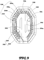
- the inner structure 246 comprises a fluid delivery structure, wherein the fluid delivery structure comprises the fluid delivery tip 222 and vacuum entry port 226 .
- the fluid delivery tip 222 has at least one aperture 224 , wherein the aperture 224 is formed at the slanted skin applying surface of the tip 204.
- the vacuum entry port 226 is also formed at the slanted skin applying surface of the tip 204 and is located away from the aperture 224.
- the intermediate structure 244 comprises the fluid electrode terminal 233 extended toward the aperture 224 to electrify the fluid when the fluid is ejected right at the aperture 244.
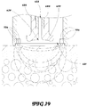
- the inner structure 246 further comprises a plurality of fluid delivery walls 245 extended between the aperture 224 and the vacuum entry port 226 to form a fluid detouring path.
- the fluid is ejected from the aperture 224, the fluid is guided and detoured along the fluid detouring path to the vacuum entry port 226. Therefore, the fluid detouring path will prolong the traveling distance of the fluid from the aperture 224 to the vacuum entry port 226.
- two fluid delivery walls 245 are extended from two opposite sides, i.e. first and second sides, of a boundary wall that partitions the inner structure 246 into two side sections and a mid-section.
- the boundary wall is the boundary of the inner structure 246 . Therefore, the boundary wall is the wall between the inner structure 246 and the intermediate structure 244.
- One of the fluid delivery walls 245 is extended from the first side of the boundary wall toward the second side thereof to form a first cornering region.
- Another fluid delivery wall 245 is extended from the second side of the boundary wall toward the first side thereof to form a second cornering region.
- the aperture 224 and the vacuum entry port 226 are formed at the two side sections and are located at two ends of the fluid detouring path.
- the fluid will travel from one side section to another side section through the mid-section, wherein the fluid will pass the first and second cornering regions.
- the fluid delivery walls 245 are extended in parallel. Therefore, the fluid detouring path is a zigzag path that the fluid travels in a zigzag manner from the aperture 224 to the vacuum entry port 226.
- An additional vacuum entry port 226a is provided at the fluid detouring path between the aperture 224 and the vacuum entry port 226.
- the size of the additional vacuum entry port 226a is smaller than the size of the vacuum entry port 226.
- the additional vacuum entry port 226a will pull a small amount of fluid first before the vacuum entry port 226 pulls the rest of fluid.
- the additional vacuum entry port 226a is located right after the second cornering region.
- the outer structure 242 , intermediate structure 244, and the inner structure 246 are integrated with the tip 204 at the skin applying surface. Only the electrode rings 231 are replaceably attached to the intermediate structure 244.
- the abrasive media 236 is optionally placed at the outer structure 242. Without the abrasive media 236, the inner abrading edge 236a, outer abrading edge 236b, and connecting abrading edges 236c at the outer structure 242 can perform the abrading operation.
- the described device basically uses the electric current to stimulate blood circulation to increase the absorption of the liquid, similar to how the skin absorbs more when exercising or sweating from heat, the pores become more permeable.
- the electric currents to be used do cause the similar effect of softening the pores to allow liquid to penetrate deeper under the skin.
- Figure 11 shows the alternative of the tip 204 that has a slanted skin applying surface, wherein the inner structure 246, including the aperture 224 , vacuum entry port 226 and fluid detouring path, remains the same. Only the outer structure 242 and intermediate structure 244 are interchanged.
- the electrode ring 231 is formed at the outer structure 242 and the abrading structure 232 is formed at the intermediate structure 244.
- Figure 12 shows another alternative of the tip 204.
- the electrode ring 231 is formed at the outer structure 242.
- the abrading structure 232 is formed at the intermediate structure 244.
- the modification in Figure 12 is that the abrasive media 236 is placed at the abrading end portion 234 and is placed at the top surfaces of fluid delivery walls 245 to increase the abrading surface of the tip 204.
- the tip 304 is an electrode skin treating tip which comprises an electrode film 304a provided at the slanted skin applying surface for generating a specific electrical current such as of electroporation, microcurrent, iontophoresis, sonophoresis, galvanic, ultrasound, ultrasonic cavitation, acoustic cavitation, mesotherapy, radio frequency, and/or hot and cold therapies.
- the electrode film 304a can also be a light film for generating a specific light wave for skin treatment.
- the electrode skin treating tip 304 can be attached to the handle 102 after the multi-functional tip 204 is removed.
- the multi-functional tip 204 and the electrode skin treating tip 304 are interchangeable. It is worth mentioning that when the electrode skin treating tip 304 is used, the fluid delivery will not be turned off. Therefore, no aperture 224 and vacuum entry port 226 is formed at the electrode skin treating tip 304.
- FIG 14 An example in Figure 14 illustrates a further modification of the tip 404 that detachably couples to the handle 102.
- the tip 404 is a micro-needle skin treating tip, which is also the multi-functional tip 204 to provide multiple functions. Similar to the multi-functional tip 204 in Figure 7 , the micro-needle skin treating tip 404 has a slanted skin applying surface, wherein the outer structure 242, intermediate structure 444, and the inner structure 246 are coaxial with each other and are formed at the slanted skin applying surface.
- the outer structure 242 of the tip 404 comprises the abrading structure 232 .
- the inner structure 246 comprises the fluid delivery tip 222 and vacuum entry port 226 .
- the difference between the multi-functional tip 204 and the micro-needle skin treating tip 404 is that the intermediate structure 444 comprises a micro-needle assembly 430 having a plurality of micro-needles 431 provided at the skin applying surface between the outer structure 242 and the inner structure 246.
- the micro-needle assembly 430 is another example of a structure to penetrate fluid delivered through the skin that further comprises a vibrator 432 supported in the tip 404.
- the vibrator 432 is connected to the control circuit 138 and is linked to the micro-needles 431. During operation, the vibrator 432 will generate a vibration force to vibrate the micro-needles 431, so that the micro-needles 431 will drive to reciprocatingly move and puncture into the skin surface.
- the vibrator 432 can also be a sonic vibrator to generate sonic wave to vibrate the micro-needles 431 . Therefore, the micro-needle skin treating tip 404 provides a micro-needling treatment for improving the skin complexion, wrinkle reduction and facial rejuvenation.
- the micro-needle skin treating tip 404 will repair skin damage from the sun, from acne, from injuries etc. By making tiny puncture wounds in the skin via the micro-needles 431 , causes a wound healing reaction that stimulates the skin to produce collagen to repair the controlled injury.
- the micro-needle assembly 430 f urther comprises a needle leveling adjustor 433 provided at the sidewall of the tip 404, wherein the level of depth of the micro-needles 431 can puncture the skin will be adjusted by the needle leveling adjustor 433 .
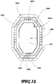
- FIG 15 shows another alternative example of the micro-needle skin treating tip 504.
- the micro-needle skin treating tip 504 has a slanted skin applying surface, wherein the outer structure 242, intermediate structure 544, and the inner structure 546 are coaxial with each other and are formed at the slanted skin applying surface.
- the outer structure 242 of the tip 504 comprises the abrading structure 232.
- the intermediate structure 544 comprises the fluid delivery structure having an aperture 524, a vacuum entry port 526, and an additional vacuum entry port 526a.
- the inner structure 546 further comprises a fluid delivery wall 545 extended between the aperture 524 and the vacuum entry port 526 to form a fluid detouring path.
- a fluid delivery wall 545 extended between the aperture 524 and the vacuum entry port 526 to form a fluid detouring path.
- the inner structure 546 comprises a micro-needle assembly 530 having a plurality of micro-needles 531 provided at the skin applying surface within the inner structure 546.
- the vibrator 432 and the needle leveling adjustor 433 as disclosed in Figure 14 will also be employed in the micro-needle assembly 530. So, the vibrator 432 will generate a vibration force to vibrate the micro-needles 531, so that the micro-needles 531 will drive reciprocatingly to puncture into the skin surface.
- the level of the micro-needles 531 will be adjusted by the needle leveling adjustor 433 in order to adjust how deep the micro-needles 431 will to be punctured into the skin surface.
- the multi-functional tip 204, the electrode skin treating tip 304, and the micro-needle skin treating tips 404, 504 are interchangeable.
- Figures 1-15 disclose examples of the present disclosure. Further, the embodiments of the present disclosure do not encompass the above examples and the method for transdermal fluid delivery.
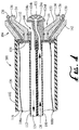
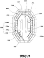
- FIG 16 shows an embodiment of the apparatus of the invention.
- the apparatus for transdermal fluid delivery comprises a handle 610, a multi-functional tip 620, a fluid delivery structure 630, and a tip driver 640.
- the handle 610 in this embodiment is an angled handle which comprises a casing 612 and a hand grip 614 inclined and extended from the casing 612.
- the casing 612 which is a hollow casing, has a front working end and a rear communicating end.
- the hand grip 614 is extended from the casing 612 between the working end and the communicating end, wherein an angle between the casing 612 and the hand grip 614 should be less than 90 degrees.
- the casing 612 comprises a detachable cap 616 detachably coupled at the casing 612, wherein the working end is defined at the detachable cap 616.
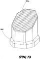
- the working end of the detachable cap 616 has a crown shaped outer edge 618 to apply pressure on the skin to perform pressure extractions.
- the handle 610 is ergonomically designed, wherein the handle 610 can be held by a right or left-handed user.
- the casing 612 can be held by the thumb and the index finger of the user and the hand grip 614 can be held by the middle finger, ring finger, little finger and palm as illustrated in Figure 16 .
- the palm of the user may not be resting on a surface being treated.
- the angled handle 610 will give the fingers of the user more precise control of the working end of the casing 612 by the support of the palm of the user. That is to say, the palm support at the hand grip 614 will relieve the pressure at the fingers when held at the casing 612.
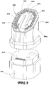
- the multi-functional tip 620 has a skin applying surface located at the working end of the handle 610, wherein the skin applying surface is capable of contacting with a user skin.
- a plurality of abrading elements 622 are provided at the skin applying surface.
- a micro-needle assembly 624 having a plurality of micro-needles is provided at the skin applying surface.
- the multi-functional tip 620 further comprises an electrode module comprising a plurality of electrodes 626 encircled around the skin applying surface in a detachably mounting manner.
- the electrodes 626 are arranged in a ring configuration to surround the skin applying surface.
- the electrodes 626 are built-in with an inner side of the detachable cap 616 adjacent to the crown shaped outer edge 618 thereof. Therefore, the electrodes 626 can be replaced, detached, and/or disposed by the detachable engagement of the detachable cap 616. That is to say, the electrodes 626 of the electrode module will be located around the abrading elements 622 and/or the micro-needle assembly 624 on the skin applying surface.
- a vacuum inlet 621 is formed between the electrodes 626 of the electrode module and the abrading elements 622 /the micro-needle assembly 624.
- the electrodes 626 will generate a desired function, such as iontophoresis, electroporation, ultrasound, or photomechanical wave.
- a desired function such as iontophoresis, electroporation, ultrasound, or photomechanical wave.
- electroporation high voltage current is applied to the skin producing hydrophilic pores in the intercellular bilayers via momentary realignment of lipids.
- ultrasound pulses are passed through the probe into the skin fluidizing the lipid bilayers by the formation of bubbles caused by cavitation.
- iontophoresis a current passed between the active electrode and the indifferent electrode repelling drug away from the active electrode and into the skin. All the electrodes 626 can be configured to provide the same desired function.
- each of the electrodes 626 can be configured to provide a particular function, so that the electrodes 626 will provide different functions at the same time when contacting with the skin. Therefore, different electrical frequencies are generated to stimulate different and wider range of cells types and skin depths from the surface to underneath so as to cause multiple reactions from the skin.
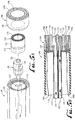
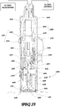
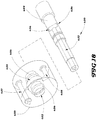
- FIGS 16 and 17 show the tip driver 640 secured and supported in the casing 612 between the working end and the communicating end.
- the tip driver 640 comprises a driving unit 642 supported in the casing 612 and a driving shaft 644 operatively extended from the driving unit 642 to the multi-functional tip 620.
- the driving unit 642 is operated to generate a movement at the skin applying surface of the multi-functional tip 620 via the driving shaft 644. For example, with the abrading elements 622 on the skin applying surface, the driving unit 642 will drive the skin applying surface of the multi-functional tip 620 to rotate via the driving shaft 644. It is preferred that the driving unit 642 will generate a reciprocating movement to rotate the multi-functional tip 620 back and forth.
- the driving unit 642 will drive the skin applying surface of the multi-functional tip 620 to slide within the casing 612 via the driving shaft 644. It is preferred that the driving unit 642 will generate a reciprocating movement to move the multi-functional tip 620 front and back, which is aligned with a centerline of the casing 612 .
- the user will hold the handle 610 stably and stationary, and the skin applying surface of the multi-functional tip 620 is driven to move to contact with the user's skin.
- the driving shaft 644 has at least a hollow portion extended to the multi-functional tip 620. It is preferred that the driving shaft 644 is made of stainless steel.
- Figures 16 and 17 further show the fluid delivery structure 630 to guide a flow of fluid to the skin applying surface of the multi-functional tip 620 .
- the fluid delivery structure 630 has a fluid channel 632 defined at the hollow portion of the driving shaft 644 and at least an aperture 634 formed on the skin applying surface of the multi-functional tip to communicate with the fluid channel 632. Therefore, the driving shaft 644 has a multifunction of driving the skin applying surface of the multi-functional tip to move and also while guiding the fluid through the fluid channel 632 to the skin applying surface of the multi-functional tip 620 at the aperture 634 at the same time.
- the fluid will be directly ejected right on the skin applying surface of the multi-functional tip 620 at the aperture 634 when the skin applying surface of the multi-functional tip 620 is contacted with the user skin, so that the fluid delivery structure 630 of the invention is the most optimal way to transdermally penetrate fluid deeper in the skin.
- the aperture 634 is located at the center of the skin applying surface of the multi-functional tip 620, wherein the abrading elements 622 are radially formed at the skin applying surface.
- a plurality of fluid distributing channels 628 are radially and outwardly extended from the aperture 634 to the electrodes 626 .
- Each of the fluid distributing channels 628 is formed at a gap between two adjacent abrading elements 622. Therefore, the fluid will be evenly distributed on the skin applying surface through the fluid distributing channels 628 and toward the electrodes 626. It is realized that the apertures 634 can also be located in other areas other than the center of the skin applying surface within the abrading elements 622, such as the sides as well.
- two or more of apertures 634 can be provided at the skin applying surface to deliver the fluid to the micro-needle assembly 624 .
- Two or more of apertures 634 can also be provided at the skin applying surface and can serve as a jet propulsion outlet to deliver the fluid in a high rate of speed.
- the multi-functional tip 620 is detachably coupled at the free end of the driving shaft 644.
- the aperture 634 is communicatively linked to the fluid channel 632 . Therefore, different types of multi-functional tip 620 are interchangeable and coupled at the driving shaft 644.
- three different types of multi-functional tip 620 are provided, i.e. the multi-functional tip 620 with the abrading elements 622, the multi-functional tip 620 with the micro-needle assembly 624, and the multi-functional tip 620 with the jet propulsion outlet. All these multi-functional tips 620 can be detachably coupled at the driving shaft 644 to guide the fluid to be ejected at the skin applying surface.
- the fluid delivery structure 630 further has at least a fluid inlet 636 transversely formed at the driving shaft 644 to guide the fluid entering into the fluid channel 632 from the fluid inlet 636 and to guide the fluid exiting toward the aperture 634 . It is preferred that two fluid inlets 636 are formed at the driving shaft 644 are perpendicular to the fluid channel 632.
- the device further comprises a support member 650 secured and supported in the casing 612 in a non-movable manner.
- the support member 650 can be removably mounted in the casing 612 to support the driving unit 642 .
- the support member 650 has a through center slot 652 , wherein the driving shaft 644 is supported by and extended through the center slot 652 of the support member 650 .
- the driving shaft 644 is movable and the support member 650 i s stationary. During the operation of the driving unit 642, the driving shaft 644 will be moved and vibrated at any direction.
- the support member 650 will restrict the movement of the driving shaft 644 in only one direction.
- the support member 650 will ensure the driving shaft 644 to be rotated within the center slot 652 or to be slid back and forth within the center slot 652 . So, the support member 650 will prevent any unwanted vibration of the driving shaft 644 .
- the support member 650 also supports the driving shaft 644 in the casing 612 because the driving shaft 644 must be long enough to extend from the driving unit 642 to the multi-functional tip 620 within the casing 612 . Therefore, the support member 650 is located between the driving unit 642 and the multi-functional tip 620, wherein the rear side of the support member 650 faces toward the driving unit 642 and the front side of the support member 650 faces toward the multi-functional tip 620.
- the fluid inlet 636 at the driving shaft 644 is located within the support member 650 .
- the support member 650 has an interior fluid cavity 654 for delivering the fluid from a fluid source to the interior fluid cavity 654 . Then, the fluid in the interior fluid cavity 654 will enter into the fluid channel 632 from the fluid inlet 636.
- the interior fluid cavity 654 is radially projected from the center slot 652 of the support member 650 , so that when the driving shaft 644 is extended through the center slot 653 , the fluid inlet 636 can communicate with the interior fluid cavity 654 .
- the driving shaft 644 is movable and extended through the center slot 652 of the support member 650 to locate the fluid inlet 636 within the interior fluid cavity 654 of the support member 650 , the fluid is able to enter into the fluid inlet 636 from the interior fluid cavity 654 when the driving shaft 644 is moved with respect to the support member 650.
- the size of the interior fluid cavity 654 is configured in response to the movement of the driving shaft 644.
- the width of the interior fluid cavity 654 should be larger than a diameter of the fluid inlet 636 .
- the width of the interior fluid cavity 654 should be larger than a traveling displacement of the fluid inlet 636.
- Two sealing elements 656 are embedded at an inner wall of the center slot 652 to fluidly seal the fluid inlet 636 within the interior fluid cavity 654 and between the two sealing elements 656.
- the sealing elements 656 are two sealing rings embedded in the inner wall of the center slot 652 to engage with the driving shaft 644, wherein the driving shaft 644 is still movable when the sealing elements 656 are engaged with the driving shaft 644 .
- the sealing element 656 will only seal the fluid within the interior fluid cavity 654 to prevent the leakage of the fluid within the center sot 652 when the driving shaft 644 is moved.
- the support member 650 further has a fluid guiding passage 658 extended from the rear side of the support member 650 to the interior fluid cavity 654, wherein the fluid is guided to flow from the fluid guiding passage 658 to the interior fluid cavity 654 before it is guided to flow to the fluid channel 632 from the fluid inlet 636.
- the fluid guiding passage 658 is an elongated passage.
- An inlet of the fluid guiding passage 658 is formed at the rear side of the support member 650 and an outlet of the fluid guiding passage 658 is formed at the interior fluid cavity 654 .
- a first fluid tube 662 is extended from the inlet of the fluid guiding passage 658 and is extended out of the communicating end of the casing 612 to operatively link to the fluid source.
- the fluid delivering path of the fluid from the fluid source to the skin applying surface of the multi-functional tip 620 is described as follows.
- the fluid is stored in the fluid source and is guided to flow from the fluid source to the fluid guiding passage 658 by the first fluid tube 662.
- the fluid source may generate an optional pumping force to pump the fluid to the fluid guiding passage 658.
- the fluid is then guided into the interior fluid cavity 654 by the fluid guiding passage 658.
- the fluid will enter into the fluid channel 632 from the fluid inlet 636 .
- the fluid will be delivered right on the skin applying surface of the multi-functional tip 620 at the aperture 634. Without the pumping force generated by the fluid source, the fluid is pulled from the fluid source, through the fluid guiding passage 658, the interior fluid cavity 654, to delivered right on the skin applying surface of the multi-functional tip 620 at the aperture 634 by the vacuum source.
- the support member 650 further has a vacuum passage 657 extended through the support member 650 and a vacuum port 659 for vacuuming the fluid after the fluid is delivered to the skin applying surface of the multi-functional tip 620 .
- An inlet of the vacuum passage 657 is formed at the front side of the support member 650 and an outlet of the vacuum passage 657 is formed at the rear side of the support member 650 .
- the vacuum port 659 is extended from the inlet of the vacuum passage 657 toward the vacuum inlet 621 around the skin applying surface of the multi-functional tip 620 .
- a second fluid tube 666 is extended from the outlet of the vacuum passage 657 and is extended out of the communicating end of the casing 612 to operatively link to a fluid reservoir.
- the fluid returning path of the fluid from the skin applying surface of the multi-functional tip 620 to the fluid reservoir is described as follows.
- the used fluid at the working end of the casing 612 is collected at the vacuum inlet 621 by the vacuum port 659 and is transmitted to the vacuum passage 657 .
- the used fluid will be delivered to a fluid reservoir by the second fluid tube 666 .
- the fluid reservoir will generate a vacuum force to create a vacuum effect at the vacuum port 659 .
- the fluid will be electrified and conducted with the electrodes 626.
- the center slot 652 , the fluid guiding passage 658, and the vacuum passage 657 are parallel with each other at the support member 650. It is important that the fluid will pass the electrodes 626 from the skin applying surface before the fluid is pulled back at the vacuum inlet 621 , so that the fluid will be electrified and conducted with the electrodes 626 to enable the liquid to penetrate into the skin longer and deeper.
- a control module 670 is provided to control the operations of the electrodes 626 and the tip driver 640.
- the control module 670 comprises a control circuit 672 operatively connected to the electrodes 626 and the tip driver 640 , and a transmission unit 674, such as a gear box, operatively connected to the driving unit 642 to adjust amplitude of the driving shaft 644.
- a transmission unit 674 such as a gear box
- the output of the rotational speed (rpm) of the driving unit 642 can be adjusted by the transmission unit 674, so that the user is able to adjust the rotational speed of the multi-functional tip 620 via one or more control switches 676 provided on the handle 620.
- the control switches 676 can also control and select the electrical frequencies of the electrodes 626 .
- An insulated wiring 627 is provided to connect the electrodes 626 with the control module 670 and is embedded in the detachable cap 616 to prevent the electric shock when the fluid is pulled back from the vacuum inlet 621.
- a terminal is provided at the rear end of the detachable cap 616 to connect with the insulated wiring 627 , so that when the detachably cap 616 is detachably coupled at the casing 612 , the electrodes 626 are electrically connected to the control module 670 . It would be acceptable that the electrodes 626 are replaceable, detachable, and/or disposable by interchanging different detachable caps 616.
- the control module 670 can also be located on the main unit (not shown) controlled by manual push button switches or controlled by a touch screen monitor that is connected to the handle 610.
- An alternative of the device, not covered by the present invention, can be formed without the driving unit, wherein the multi-functional tip 620 is driven to move by the flow of the fluid via the fluid delivery structure 630.
- the multi-functional tip 620 is driven to move by the flow of the fluid via the fluid delivery structure 630.
- the fluid is guided to flow at the fluid channel 632 in a vortex manner to drive the multi-functional tip 620 to rotate.
- the apertures 634 on the skin applying surface have an ejecting angle, so that during the ejection of fluid at the apertures 634 , the multi-functional tip 620 is propelled to rotate.
- Figure 19 shows a modification of the electrode module which comprises two or more different electrodes 726 .
- three different electrodes 726 are utilized and are configured into an inner electrode ring, an intermediate electrode ring, and an outer electrode ring which are coaxial with the skin applying surface of the multi-functional tip 620 orderly.
- the three electrode rings will generate different electrical frequencies to stimulate different and wider range of cells types and skin depths from the surface to underneath so as to cause multiple reactions from the skin. That is to say, the three different electrodes 726 can improve the skin structure affecting multiple layers of the skin, such as, epidermis, dermis, and hypodermis.
- the fluid will guide to pass through different electrodes 726 from the abrading elements 622 on the skin applying surface to the vacuum inlet 621 at the perimeter of the outer electrode ring.
- the apparatus of the present invention is an innovative apparatus of treating the skin to transdermally penetrate fluid deeper into the skin by means of simultaneous (1) abrasive peeling via the abrading elements 622, (2) electrical stimulation via the electrodes 626 , (3) liquid infusion via the fluid delivered onto the skin applying surface, in order to improve the skin structure affecting multiple layers of the skin, such as, epidermis, dermis, and hypodermis.
- the fluid will be delivered right on the skin applying surface to evenly distribute on the abrading elements 622 and then to electrify with the electrodes 626 before the fluid is vacuumed back through at the vacuum inlet 621 .
- the traveling path of the fluid will be prolonged between the aperture 634 and the vacuum inlet 621 to ensure the fluid to pass through the abrading element 622 and the electrodes 626.
- the skin abrading operation is automatic by the movement of the multi-functional tip 620. Therefore, the apparatus of the present invention produces a new singular treatment to include three different skin treatment methods in one single device. That is to say, the user can simply hold the handle 610 stationary and place the skin applying surface of the multi-functional tip 620 on the skin surface with three different functions operating in conjunction with each other.
- Therapeutically when the interaction between the fluid and electrodes 626 occurs, it delivers a medicine in the fluid through the skin surface. It is a non-invasive method to enhance the effects on skin permeation and to enhance the absorption of medicine across the skin surface. It drives a charged substance, such as medication or a bioactive agent, transdermally by repulsive electromotive force, through the skin surface.
- the three different skin treatment methods are interlinked with each other and are not independent functions from each other. That is to say, the three different skin treatment methods enhance each other's functions as a whole.
- the fluid will be delivered right on the skin applying surface to directly contact with the skin surface for liquid infusion.
- the fluid will also be flush to the skin surface when the abrading elements 622 are applied on the skin surface.
- the fluid will also interact with the electrodes 626 for electrical stimulation on the skin surface. It is worth mentioning that due to the vacuum effect at the vacuum inlet 621 , the fluid will be forced to vacuum at the vacuum inlet 621 from the apertures 634 to ensure the fluid to pass through the abrading elements 622 and the electrodes 626 before the fluid is pulled back at the vacuum inlet 621.
- the method which does not form part of the present invention, for transdermal fluid delivery comprises the steps as follows:
Description
- The present invention relates to a skin treatment tool. More particularly, the present invention relates to an apparatus for transdermal fluid delivery.
- Current techniques for superficial skin resurfacing, known as microdermabrasion, treat the outer epidermal layer of the skin by removing the superficial layer to induce the body's own natural wound healing response. It is known in the art to couple microdermabrasion with fluid delivery to enhance therapeutic effects. However, combined microdermabrasion/fluid delivery treatments are hindered by the protective barrier function of the stratum corneum which limits the depth of penetration and absorption to the surface of the skin when drugs and/or fluids are applied to the skin.
- Other techniques for skin enhancing include transdermal drug delivery employing an electrical current (e.g., skin electroporation) are known. However, these techniques have limited results based on: 1) the lack of an efficient fluid supply/return system using a vacuum; 2) the impedance of the stratum corneum which limits the efficacy of the current technologies of electrical penetration of drugs and/or fluids; and 3) the optimal permeation structure of the skin occurs during application of an electrical current and only lasts a few seconds after application of the electrical pulse.
- Known technologies for delivery of an electro-current to the skin suffer from one or more of the following deficiencies which lead to limited results, including, a lack of an efficient fluid supply/return system using a vacuum source; an inability to simultaneously apply fluid and electro-current to the skin; as a means to lower the impedance of the stratum corneum.
- The major disadvantage of the conventional art is that the fluid cannot be directly applied from on the abrading surface to the skin. An injection end of a tube is extended close but separate to the abrading surface so that the fluid is injected to the abrading surface through the injection end. The fluid flowing through injection end will not be evenly distributed the fluid on the abrading surface when applying on the skin. Most of the fluid in fact will never be in contact with the skin and be wasted because the fluid cannot fully penetrate between the skin and the abrading surface of the skin. More importantly, the individual injection tube structure is used when there is a motor utilized in the microdermabrasion device.
- US. Pub. No.
2010/0049177 A1 , Boone, discloses a microdermabrasion system which comprises a tip having an abrading surface and a side surface, wherein a plurality of fluid channels terminate on the side surface of the tip. That is to say, the fluid cannot be directly delivered through to the abrading surface of the tip. Boone further discloses a plurality of radiation sources evenly distributed around a perimeter of the tip and between the tip and the vacuum opening. This structure has a major disadvantage that the fluid will only deliver to the radiation sources but not the abrading surface because of the vacuum effect at the vacuum opening. Therefore, the user must hold the hand piece of Bonne to manually move to the tip on the skin. Also, Boone describes using radio frequency to heat below the skin but does not describe any relationship to the fluid delivery or abrasive. It is a means to penetrate heat into deeper layers to cause tightening of the skin but do not create a transdermal pathway for fluid. This type of frequency also has no relationship with abrasion and liquid. - US. Pub. No.
2004/0138680 A1, Twitchell et al. , disclosed a microdermabrasion apparatus comprising an exfoliation tip mechanically coupled to a motor via a shaft and a tube extended to a vacuum pace in the suction cup. The suction cup as taught by Twitchell et al. is arranged in such a way that the user's skin is pulled partially into the suction cup where a vacuum is formed within the space in the suction cup. That is to say, no fluid is applied onto the exfoliation tip and no fluid is sucked back via the tube. -
US. Pat. No. 8,343,116, Ignon et al. , disclosed a skin treatment system comprising a tip having at least one abrasive element configured to abrade skin, a delivery port and a suction port extended to a working surface of the tip, wherein the delivery port delivers fluid from a first canister to the working surface of the tip and the suction port sucks the fluid back to a second canister from the working surface of the tip. The disadvantage of the system as taught by Ignon et al. is that the fluid will be sucked back by the suction port right after the fluid is delivered to the working surface of the tip. That is to say, the fluid will not be applied long enough on the working surface of the tip. Also, without any motor incorporated within the system as taught by Ignon et al., the user must hold the hand piece of Ignon et al. to manually move the tip over the skin in a scratching motion. Thus, the system as taught by Ignon et al. makes it impossible to incorporate with any electrodes because both the delivery port and suction port are located right at the working surface of the tip. So the fluid cannot be delivered to be in contact with any electrode after it is vacuumed back by the suction port. -
FR284556 WO 2014/004644 discloses a skin treatment device. As described in FR56, which may be regarded as a closest prior art, the interior components of the device of FR56 are held within the walls of the handle (1) of that device with no other supporting structure such as a casing between those interior components and the handle (1). In FR56 device both the fluid inlet pipe (3) and the fluid outlet conduit (6) have their entry and exit ports respectfully on one side of the handle (1). The FR56 device has a multi-functional tip having a skin-applying surface, a support member within a handle structure, comprising a fluid delivery structure, a fluid returning structure and a tip driver. The skin applying surface of the multifunctional tip comprises a plurality of abrading elements. The support member comprising the fluid delivery structure, the fluid returning structure and the tip driver is secured inside a casing within handle structure. The tip driver comprises, a driving unit and a driving shaft, wherein the driving shaft is operatively extended from the driving unit to the multifunctional tip through a center slot of the support member, wherein the driving shaft is movable and the support member is stationary. The multifunctional tip is detachably coupled at a free end of the driving shaft, wherein the shaft has a hollow portion extended to the multi-functional tip, wherein a fluid delivery channel of the fluid delivery structure is defined at the hollow portion of the driving shaft, wherein the fluid delivery structure further has a fluid inlet transversely formed at the driving shaft to guide a fluid from an interior fluid cavity of the support member into the fluid delivery channel defined at the hollow portion of the driving shaft; wherein the fluid delivery structure has an aperture located at an axial center of said the applying surface of the multi-functional tip to communicate with the fluid delivery channel defined at the hollow portion of the driving shaft and deliver fluid to the skin surface; wherein the driving shaft has a dual function of the skin applying surface of the multi-functional tip to rotate while concomitantly guiding a flow of a fluid through the fluid delivery channel to the skin applying surface of the multi-functional tip at the aperture; wherein the driving unit is operated to generate a movement by a motor at the skin applying surface of the multi-functional tip through the driving shaft and wherein the fluid returning structurecomprises a vacuum inlet, a vacuum port and a vacuum passage, wherein the vacuum passage is extended through the support member to transport a used fluid collected by the vacuum inlet from the multifunctional tip by the vacuum port to a reservoir at a rear end of the support member. - Accordingly, there is a need for a skin resurfacing and enhancement system with an enhanced fluid delivery/fluid return capacity which also improves the permeation structure of the skin. The present invention discloses an apparatus for transdermal fluid delivery which provides three different skin treating functions for skin treatment to transdermally penetrate fluid deeper into the skin by means of simultaneous 1) abrasive peeling 2) electrical stimulation 3) liquid infusion in order to improve the skin structure affecting multiple layers of the skin, such as the epidermis, dermis, and hypodermis. The present invention also provides an innovative structure to simultaneously guide the fluid to the tip surface and to prolong the traveling path of the fluid.
- According to the present invention, a device for a combination treatment of the top and bottom layer of a skin surface are described. The device comprises features according to
claim 1. - A method of treating the skin to transdermally penetrate fluid deeper into the skin by means of simultaneous 1) abrasive peeling 2) electrical stimulation 3) liquid infusion to improve the skin structure affecting multiple layers of the skin, such as, epidermis, dermis, and hypodermis is also disclosed, however does not form part of the present invention. The apparatus of the present invention serves as an all-in-one handheld skin treatment device.
- The device and methods described herein allow for the simultaneous deep penetration of fluid through the skin by applying an electric current and an abrasive media in the working end of the device to increase skin's permeability. Techniques known as electroporation, ultrasound, and other electrical induced therapies, etc., which use electric currents to go deeper past the stratum corneum to stimulate cells underneath the skin may be employed in the device. The combination of the electrical induced therapies and microdermabrasion create aqueous pathways to increase the permeability of the drugs and/or fluids which are delivered from a supply and return reservoir by a vacuum system within the device. A pressure mechanism may also be employed as part of the device.
- In a preferred embodiment, the tip of the device has an outer structure having one or more electrodes and an intermediate structure having an abrading end portion, where the abrading end portion has an abrasive media. The tip of the device also has an inner structure which has one or more apertures for fluid delivery. That is to say, the inner structure is located at the center of the tip. The outer structure is located at the periphery of the tip. The intermediate structure is located between the inner structure and the outer structure. The outer structure, intermediate structure, and the inner structure are coaxial with each other and are in a ring shape. Preferably, the outer structure and intermediate structure form an outer ring and intermediate ring respectively at the tip. The outer ring and intermediate ring can be formed in a circular shape or a non-circular shape. Therefore, the abrading end portion forms at the intermediate ring and encircles the fluid delivery. The electrodes are aligned at the outer ring to encircle the abrading end portion at the intermediate ring. Preferably, at least one of the structures is removable, and more preferably, each of the outer structure, intermediate structure, and inner structure are removable, and most preferably, at least one of the structures is disposable.
- A method for treating a skin surface of a patient is disclosed, but does not form part of the invention. According to the method, first an abrasion device for treating a skin surface of a patient is selected, wherein the abrasion device comprises one or more electrodes, an abrading end portion having an abrasive media, and one or more apertures for fluid delivery. Next, the abrading end portion of the device is placed on the skin surface of the patient. The patient's skin is then treated by applying the abrasive media to the skin surface of the patient, delivering fluid to the skin surface of the patient, and applying an electrical current to the skin surface of the patient. The patient skin is treated with abrasive media, fluid delivery, and current delivery in the order stated above, simultaneously, or another order. Vacuum may then be applied to the skin surface of the patient.
- A kit for treating a skin surface of a patient is also described. The kit comprises a skin abrading device comprising a tip, wherein the tip has at least one current delivery tip having one or more electrodes, a plurality of abrading tips, wherein each abrading tip has an end portion with an abrasive media, and wherein the plurality of abrading tips are removable from the device and interchangeable, and a fluid delivery tip having one or more apertures for fluid delivery. Preferably, the tip further comprises a vacuum entry port and also preferably, each of the plurality of abrading tips has a grit size, and the grit size varies for each abrading tip.
- According to the invention a device for treating a skin surface of a patient, comprises a multi-functional tip having a skin applying surface, a fluid delivery structure, and a tip driver.
- The tip driver comprises a driving unit and a driving shaft operatively extended from the driving unit to the multi-functional tip, so that the driving unit is operated to generate a movement at the skin applying surface of the multi-functional tip. The driving shaft has at least a hollow portion extended to the multi-functional tip.
- The fluid delivery structure is arranged to directly guide a flow of fluid on the skin applying surface of the multi-functional tip. The fluid delivery structure has a fluid channel defined at the hollow portion of the driving shaft and at least an aperture formed at the skin applying surface of said multi-functional tip to communicate with the fluid channel. Therefore, the driving shaft provides multifunction of driving the skin applying surface of the multi-functional tip to rotate and guides the fluid through the fluid channel to the skin applying surface of the multi-functional tip at the aperture at the same time.
- For a more complete understanding of the present invention with its objectives and distinctive features and advantages will be described herein below.
- These and other features, aspects and advantages of the present invention will become better understood from the following description, appended claims, and accompanying figures where:
-
Figure 1A shows an exemplaryskin abrading device 100 which does not form an embodiment of the present invention. -
Figure 1B is partial side cut-away view of thedevice 100, shown inFigure 1A . -
Figure 2A is a top perspective view of thedevice 100, shown inFigure 1A and Figure 1B , showing thetip 104 of thedevice 100. -
Figure 2B and Figure 2C are alternate examples for thetip 104 of thedevice 100, which do not form an embodiment of the present invention. -
Figure 3A is a side view of one embodiment of thedevice 100, having a plurality of removable, exchangeable, and attachable tips. -
Figure 3B is a side view of another example of one of the tips shown inFigure 3A . -
Figure 4 is a partial side cut-away view of thedevice 100 having a wide-angle tip 104 which does not form an embodiment of the present invention. -
Figure 5A is a side view of another example of thedevice 100, having a plurality of removable, exchangeable, and attachable tips, where theelectrodes -
Figure 5B is a partial side cut-away view of thedevice 100 shown inFigure 5A , havingelectrodes -
Figure 6A shows an alternate example of theskin abrading device 100 which does not form an embodiment of the present invention, having a dividedhandle -
Figure 6B is a cut-away view showing the dividedhandle Figure 6A . -
Figure 7 is a perspective view of the tip detachably coupling at the handle which does not form an embodiment of the present invention. -
Figure 8 is an exploded view of the tip according to the above example, showing the replacement of the electrode rings. -
Figure 9 is a top view of the tip according to the above example. -
Figure 10 is a top view of the tip according to the above example, showing one electrode ring at the intermediate structure. -
Figure 11 is a top view of the tip according to the above example, showing the alternative of the outer and intermediate structures. -
Figure 12 is a top view of the tip according to the above example, showing how to increase the abrading surface of the tip. -
Figure 13 is a perspective view of the tip detachably coupling at the handle according to another example, which does not form an embodiment of the present invention, showing the electrode skin treating tip. -
Figure 14 is a perspective view of the tip detachably coupling at the handle according to another example, which does not form an embodiment of the present invention, showing the micro-needle skin treating tip. -
Figure 15 is a modification of the micro-needle skin treating tip according to the above example. -
Figure 16 shows an apparatus for transdermal fluid delivery according to the embodiment of the present invention. -
Figure 17 is a sectional view of the apparatus inFigure 16 . -
Figure 18 is an exploded view of the driving shaft and the support member of the apparatus according to the present invention. -
Figure 19 shows a modification of the electrode module of the apparatus according to the present invention. - According to the present invention, a device, i.e. a microdermabrasion device, for increasing the permeability of the skins surface to fluid and/or drug delivery is described. In general, permeation of drugs and/or fluids through the skin occurs at a slow rate, if at all. The stratum corneum acts as a barrier that limits the penetration of substances through the skin. Application of high-voltage pulses to the skin increases its permeability (electroporation) and enables the delivery of various substances into and through the skin. The application of electroporation to the skin has been shown to increase transdermal drug delivery. Moreover, electroporation, used alone or in combination with other enhancement methods, expands the range of drugs (small to macromolecules, lipophilic or hydrophilic, charged or neutral molecules) that can be delivered transdermally. The efficacy of transport depends on the electrical parameters and the physicochemical properties of drugs. The in vivo application of high-voltage pulses is well tolerated.
- According to the embodiment of the invention, a device according to
claim 1 and comprising an abrading surface, fluid delivery, current delivery; and fluid vaccuation is described. The device enhances fluid delivery through the stratum corneum by first delivering an abrasive media to the surface of the skin to prepare the skin for fluid delivery. Next, the device delivers fluid to the surface of the skin, with simultaneous current delivery (electroporation). The combination of skin abrasion, followed by simultaneous fluid delivery with electroporation allows for deep penetration of fluid through the skin by increasing the skin's permeability. In addition to enhancing fluid delivery through the stratum corneum, the device resurfaces the outer surface of the skin, removing dead skin cells and the outer layer of dermis, along with other superficial imperfections. Unlike known microdermabrasion devices, the results achieved with the device of the present invention will have enhanced and longer lasting results, namely, because skin enhancing fluids and drugs are delivered more deeply into the skin with the simultaneous electrooporation, and the electrical induced therapy itself has skin enhancing properties, such as increased collagen production, muscle tone, and overall skin elasticity and firmness. - The device and methods, which do not form part of the present invention, being described herein have an efficient fluid supply/return for transdermal/topical delivery of skin enhancing drugs and medicaments. This feature of the invention has been found to be particularly important since presently known technologies use a gel which is applied to the skin which limits the penetration of effective ingredients because of the greater molecular weight of the gel. Macromolecule delivery through a liquid, which can be accomplished with the present invention, is accordingly more effective than prior art technologies which use a gel. The application of an abrasive as described herein solves this issue of lowering the impedence of the stratum corneum thus further improving drug delivery to the skin. Accordingly, the device of the present invention, which include fluid delivery with electro-current and a vacuum source, enable simultaneous application of fluids containing skin enhancing drugs, with increased topical delivery through an abrading surface, to achieve the maximum effect. The abrading surface, which is applied to the skin preferably prior to fluid/drug delivery, increases topical drug delivery and penetration of the drug to the lower layers of the skin. These features of the invention are an improvement over prior art technologies which lack a fluid delivery and a vacuum source and more particularly in combination with an abrading surface and electro-current application to accomplish skin resurfacing and enhancement.
- As used in this disclosure, the term "comprise" and variations of the term, such as "comprising" and "comprises," are not intended to exclude other additives, components, integers or steps.
- An exemplary device for enhancing fluid delivery to the skin is described. Referring now to
Figure 1A , askin abrading device 100 having fluid and current delivery is shown. Thedevice 100 comprises ahandle 102, atip 104, and adistal end 106. Positioned at the distal end are one or more conduits such as anelectrical conduit 108, afluid delivery conduit 110, and avacuum conduit 112. Theskin abrading device 100 may further include one or more switches for controlling thedevice 100 such as aswitch 114 and/or 116 for controlling electrical current delivered via theelectrical conduit 108, and/or control vacuum and/or fluid delivery from the fluid delivery andvacuum conduits - As shown in
Figure 1A , thehandle 102 may be cylindrical with molded hand grip, or it may have other configurations such as cylindrical (without a molded hand grip), or other variations, including elliptical, square, rectangular, and variations thereof. Thehandle 102 may be formed of various materials as known to those in the art including any suitable plastic, metals, such as aluminum, stainless steel, and other alloys, and combinations of metal and plastic. Preferably, thehandle 102 is made from a high density plastic material. - Referring now to
Figure 1B , a partial side cut-away view of thedevice 100 shown inFigure 1 is shown. As shown inFigure 1B , thehandle 102 of thedevice 100 comprises an interior 118 and anouter casing 120. Thefluid delivery conduit 110 is positioned in theinterior 118 of thehandle 102 and delivers fluid 120 from a reservoir (not shown) in an adjunct device through thefluid delivery conduit 110 and out thetip 104 of thedevice 100. The fluid 120 exits thetip 104 through afluid delivery tip 122 having one ormore apertures 124. Also positioned within theinterior 118 of thehandle 102 is thevacuum conduit 112 which pulls a vacuum from a vacuum pump (not shown) stationed in an adjunct device through thevacuum conduit 112. Thevacuum conduit 112 has avacuum entry port 126 positioned within thetip 104 for evacuating fluids and other debris from the surface of the skin. Theinterior 118 of thedevice 100 has one or moreelectrical conduits electronics board 128, which then delivers current to one ormore electrodes 130, shown as 130a and 130b. Positioned within thetip 104 is an abradingstructure 132 having an abradingend portion 134, which comprises anabrasive media 136. Within either the interior 118 of the device,electronic control circuitry 138 may be positioned for controlling current to theelectrodes 130. - Referring now to
Figures 2A, 2B, and 2C , examples of thetip 104 of thedevice 100 are shown. As shown inFigure 2A , thetip 104 may be somewhat tapered at the end, or in other examples, thetip 104 may be substantially cylindrically shaped or other, such as oval shaped, squared, or rectangularly shaped. As also shown inFigure 2A , preferably, thefluid delivery tip 122 is domed shaped, having a plurality ofapertures 124, such that a spray effect is achieved with thefluid delivery tip 122. (However, in other examples, thefluid delivery tip 122 may be flat, and/or have asingle aperture 124.Multiple apertures 124 spread the liquid evenly along the area of the skin. Preferably, thefluid delivery tip 122 is positioned with respect to thetip 104,electrodes 130, and abradingstructure 132 such that the fluid delivery tip extends slightly beyond or substantially flush with the abradingstructure 132. - The
tip 122 of the dome creates a planar surface of the skin preventing the vacuum suction from causing a subcutaneous hemotoma which is caused when the lining of blood vessels are damaged and blood escapes through the skin. - The vacuum entry port is positioned with respect to the
tip 104, such that thevacuum entry port 126 minimizes skin trauma and ruptured capillaries, veins and arteries from thevacuum 124, yet creates a suitable vacuum to evacuate fluid and debris from the skin's surface. According to an example, thevacuum entry port 126 is positioned on thetip 104 such that when thetip 104 of thedevice 100 is applied to the surface of the skin, a space is created between thetip 104 and thevacuum entry port 126 to create a vacuum, known in the art as a closed loop system. - In another example, the
fluid delivery tip 122 is substantially flush to the skin with respect to the abradingend portion 134 of the abradingstructure 132 and theelectrodes 130 such that when thedevice 100 is applied to the skin, the skin stays relatively flat during treatment. According to this example, when theabrasive media 136,vacuum 124,fluid 120, and electric current 140 are applied to the skin with the configuration described with respect to this example, having the various structures of thetip 104 substantially flush to the skin minimizes the possibility of skin trauma associated with the pulling up of skin in a space ofvacuum 124. - In another example, the
vacuum entry port 126 can be positioned in other portions of thetip 104 to provide an optimal vacuum of concurrent liquid delivery and/or removal of skin debris. However, thevacuum entry port 126 is preferably positioned to keep a higher level of fluid within the tip of the handle during treatment so as to have a higher absorption and penetration rate of ingredients contained in the fluid, into the skin, while still evacuating skin debris and preventing the fluid 120 from flowing away from the desired treatment area and/or falling off the skin. - The abrading
structure 132 is positioned with respect to thetip 104, such that the abradingend portion 134 of the abradingstructure 132 is substantially flush to the surface of the skin. In other examples, the abradingstructure 132 may be lowered or raised with respect to the end of thetip 104 to provide skin contact, as desired by the user. - In this example, the abrading
structure 132 has a range of abrasiveness on theabrasive media 136 from a substantially smooth surface (no abrasion) to very abrasive depending on the treatment type. As shown inFigures 1B , and2A -2B, the abradingstructure 132 is positioned on the outer edge of both a fluid supply, i.e., thefluid delivery tip 122 andvacuum port 126 and on the inside of theelectrodes 130. However, other arrangements of the abradingstructure 132,electrodes 130, andfluid delivery tip 122 andvacuum port 126 are possible, as will be understood by those of skill in the art. - The abrading
structure 132 may be reusable or disposable, in part or entirely. For example, the abradingend portion 134 and theabrasive media 136 are integral to the abradingstructure 132. According to this example, the abrading structure may be reusable or disposable in part or entirely. When the abradingstructure 132 is reusable, it is preferably designed to be sanitized and cleaned between uses and reused. In an alternate example, theabrasive media 136 is positioned on the abradingend portion 134 in a removable fashion, such as a removable strip. According to this example, the abradingstructure 132 is generally reusable and theabrasive media 136 on the abradingend portion 134 is preferably disposable. - The
abrasive media 136 comprises a material suitable to abrade the surface of the skin such as sand paper, rough textiles (such as dermal grade fabrics that are used in cosmetic microdermabrasion, typically made from 100% medical grade nylon and have a plurality of coatings and finishes), wire brushes, carbon fibers, and micro-needles. The material can be conductive or non-conductive. According to one example, theabrasive media 136 comprises a non-conductive sand paper. In one embodiment, the sand paper is white aluminum oxide, a non-conductive material, readily available at low cost in medical grade. This material is able to withstand elevated temperatures, such as those typically present in any vitrification process that may be necessary for high volume binding/fabrication to produce the abrasive tip. According to other examples, a material softer than aluminum oxide is preferred so that the material is less irritating to the skin than aluminum oxide. According to this example, the abradingmedia 136 comprises polymeric beads. Generally, polymeric beads provide a softer, less irritating material than aluminum oxide. However, other materials may be used as the abradingmedia 136, where the material is selected based on the particular individual to be treated and the purpose of the treatment. Accordingly, for different individuals, different materials may be substituted for the above-listed materials. In other examples, theabrasive media 136 comprises a conductive material. Suitable conductive materials include, but are not limited to, metals, carbon, conductive polymers and conductive elastomers. - The abrading
end portion 134 may have a variety of suitable thicknesses and diameters. According to one example, abrasive particles are coated onto the abrading end portion of the abradingstructure 132. In some examples, the abradingstructure 132 and abradingend portion 134 comprise a unitary plastic structure, such as acrylonitrile butadiene styrene (ABS). According to this example, the abrasive media is an abrasive coating adhered to the abradingend portion 132, or theabrasive media 136 is of a unitary construction with the abradingstructure 132 and abradingend portion 134. According to one example, the abrasive media comprises abrasive particles which are adhered to the abradingend portion 134, where the thickness of theabrasive media 136 is defined by the grit size of the abrasive particles. According to this example, the abrasive particles are generally of a size ranging from about about 50 to 300 microns (50 to 300 grit), and typically about 163 to 173 microns (100 to 120 grit) and may comprise carborundum (aluminum oxide), sodium bicarbonate, polymeric particles, and the like. Coarser particles (at the lower ends of the grit ranges (about 35 to 50, and typically less than 100), micron ranges (about 439 to 313, an typically less than 163)) may also be provided for use in initial treatments, or treatments on coarser areas of the skin (such as arms), while finer particles (at the higher ends of the grit ranges about 300 (57 microns) and above) may be employed for subsequent treatments. Alternately, the abradingend portion 134 may be formed by knurling, machining, laser treatment or otherwise mechanically or chemically treating the end of the abradingend portion 134 to provide an integralabrasive media 136 which has a unitary construction with the abrading end portion and abradingend structure 132. In an example, theabrasive media 136 is abrasive particles having a grit size of about 120 or lower (approximately 137 microns in diameter). - Typically the abrading
end portion 134 will have a thickness ranging from 0.5 microns to 150 microns, preferably ranging from 15 microns to 120 microns. The diameter of the abradingend portion 134 is variable depending on the type of application. For example, in applications having a small area to be permeabilized, the abradingend portion 134 can have a diameter of up to several micrometers, such as from 1 to 25 microns. For applications having a larger area to be permeabilized, the abradingend portion 134 can have a diameter of up to several inches, such as from 0.1 to 5 inches (2.5 mm to 127 mm). - According to the present example, a current 140 (not shown) is delivered from the
device 100 to the surface of the skin through one ormore electrodes 130. Theelectrodes 130 can be a single electrode, or a plurality of nodes or combination thereof, and may further have a variety of configurations and dimensions, such as nodes, bars, etc., as will be understood by those of skill in the art. - Electrical currents, known for application to the skin, which may be used include:
- a. Electroporation. Electroporation refers to the application of electric pulses to increase the permeability of cell membranes. Electric pulses are applied to skin cells to increase membrane permeability.
- b. Microcurrent. Microcurrent refers to the application of a small current used in a noninvasive electrotherapy technique where electrodes are applied at acupuncture points. In general, 10-500 microamps (Ua) are applied to the surface of the skin and for optimal effectiveness, the current applied to the skin should not cause an actual "visual" contraction of the facial muscles. In some applications, electroporation refers to the process of applying a microcurrent to the surface of the skin.
- c. Iontophoresis. Iontophoresis refers to a therapeutic type of transcutaneous drug delivery in which electric current is applied to the skin to enhance absorption of large polar or hydrophilic molecules and peptides-e.g., insulin, and control therapeutic delivery. A galvanic current is applied an ionizable agent in contact with a surface of the skin, by means of an appropriate electrode, to hasten the movement into the tissue of the ion of opposite charge to that of the electrode. Accordingly, skin enhancing agents which are polar or hydrophilic may be delivered into the skin.
- d. Sonophoresis. Sonophoresis refers to a process that exponentially increases the absorption of semisolid topical compounds (transdermal delivery) into the epidermis, dermis and skin appendages. Sonophoresis occurs where ultrasound waves stimulate micro-vibrations within the skin epidermis and increase the overall kinetic energy of molecules making up topical agents. Skin enhancing agents may be mixed with a coupling agent (gel, cream, ointment) to transfer ultrasonic energy from the ultrasound transducer (i.e., electrode) to the skin and enhancing drug transport through the skin.
- e. Galvanic. Galvanic or Galvanic current refers to the current which is the electrical current used in the process of Iontophoresis.
- f. Ultrasound. Ultrasound or ultrasonic current refers to the current used in Sonophoresis. Ultrasound is cyclic sound pressure with a frequency greater than the upper limit of human hearing. Although this limit varies from person to person, it is approximately 20 kilohertz (20,000 hertz) in healthy, young adults and thus, 20 kHz serves as a useful lower limit in describing the ultrasonic current applied via the electrodes.
- g. Ultrasonic Cavitation. Ultrasonic Cavitation refers to an advanced ultrasonic machine having 3 MHz and 1MHz ultrasound frequencies for the body and a 1.4MHz ultrasonic frequency for the face, and an ultrasonic cavitation wavelength at 47 KHz. In Ultrasonic Cavitation, the ultrasonic waves are able to act on the skin surface (3MHZ ultrasound), providing skin tightening as well in the deep layers, (cavitation) providing real results, after the treatment, in terms of cellulite and localized adiposity. It has been shown to be able to eliminate centimetres of belly, buttocks, hips and thighs without any side effects. Ultrasonic waves in a specific range from 20 to 70 KHz are able to cause the "cavitation" effect: focused high energy waves which creates micro bubbles of vapor inside the adiposities and in the interstitial liquids of cellulite.
- h. Acoustic Cavitation. Acoustic Cavitation refers to a non-flowing system where the ambient pressure can be varied by sending sound waves through a liquid. The ultrasonic sound waves are made up of alternate compressions and rarefactions. During the rarefaction cycle (low pressure) a lot of microscopic bubbles will grow and during the compression cycle (high pressure) each bubbles undergoes a collapse or implosion.
- i. Mesotherapy. Mesotherapy refers to a procedure in which multiple tiny injections of pharmaceuticals, vitamins, etc., are delivered into the mesodermal layer of tissue under the skin, to promote the loss of fat or cellulite.
- j. Radio Frequency. Refers to a procedure using a beam of radio frequency energy to target deeper layers of the skin by heating them up. This creates stimulation of the skin and in particular, the collagen, a substance which gives elasticity to the skin. The radio frequencies cause water molecules in the deeper layers of skin to vibrate. This in turn creates friction which causes the heating effect. When heat is applied to collagen fibres, they shrink and tighten up, and over time following the treatment, new collagen also forms.
- k. Hot and cold therapies. Refers to using an electrical current and other modalities to create different adjustable temperatures ranging from hot (up to 140 degrees Fahrenheit) to cold (down to 5 degrees Fahrenheit) to treat the surface layer skin by softening and/or tightening collagen fibers.
- In an example, a microcurrent is applied to the skin, i.e., electroporation. According to this example, the current of the
device 100 is set for a wave form with power between 10-500 microamps (Ua). The current 140 (not shown) is delivered through thedevice 100 and through one ormore electrodes 130 to the surface of the skin. Treatment can be substantially stationary in certain areas, or vary in the degree of motion, up to sweeping lines. - According to another example, a combination of two or more frequencies of current are applied from the
device 100 to a patient. Accordingly, in some examples the device is capable of delivering a plurality of different frequencies (i.e., types) of current, either individual applied or concurrent. For example, an ultrasonic current may be applied from thedevice 100 to a patient, followed by delivery of a microcurrent from thedevice 100 to the same patient. The treatment may be in one treatment area, or over a plurality of treatment areas, such the delivery of microcurrent to the face, followed by delivery of ultrasonic current to the arms. The plurality of frequencies may be used on one patient for application of different electric currents. For example, ultrasound and microcurrent have different ways of penetrating fluids and treating the skin. The concurrent combination of these and other electric modalities shown indevice 100 is to provide a more effective treatment. - Referring again to
Figure 1B ,fluid 120 is delivered from a fluid reservoir (not shown), which may be either part of the handle or in a separate reservoir, such as a plastic or glass tube serum, through thefluid delivery conduit 108 and out thefluid delivery tip 122 in thetip 104 of thedevice 100. Fluid delivery may be used in the device for cleaning of the skin, as a vehicle for delivery of a therapeutic agent, or it may be the therapeutic agent itself, and/or the fluid may be an ionic agent to facilitate delivery of current 140 through theelectrodes 130. The fluid may include one or a plurality of suitable skin enhancing agents, and/or conductive ingredients, or other suitable agents for skin cleaning and skin enhancement or facilitation of current delivery, such as water, salts, ionic or non-ionic surfactants, preservatives, alcohol, glycerol, gel, and other similar agents. Various mixtures of these agents may be formulated into fluids with various conductivity levels, depending on the desired application. Preferably, at least one of the fluids used is a "highly conductive fluid" or a "fluid with a high conductivity" meaning a fluid with a conductivity from about 1,000 to about 100,000 (µSiemens/cm) to facilitate current delivery. Other fluids, such as a "fluid with a low conductivity", meaning a fluid with a conductivity from about 0.1 to about 999 (µSiemens/cm), are used in other applications, such as cleaning, and/or delivery of a skin enhancing or therapeutic agent. A highly conductive fluid is used to provide a conductive path through the skin. At least one fluid with a conductivity of at least 500 to about 50,000 uSiemens/cm is used. - Therapeutic or skin enhancing fluids useful in the
device 100 may be of a variety of therapeutic agents. For example, the fluid may be a skin treatment liquid, a lotion liquid, and/or a vitamin liquid, or a combination thereof. The fluid may also be a pharmacologically-active agent, where the fluid carries a chemical agent of a suitable concentration. Examples of such agents include TCA (trichloroacetic acid), a glycolic acid including an alphahydroxy acid (AHA), a lactic acid, a citric acid, and phenol, alone or in combination with other agents or fluids. Examples of other therapeutic or skin enhancing agents include type A botulinum toxine, phosphatidylcoline, aminophylline, hyaluronic acid, L-carnitine, vitamins, amino acids, collagen, lidocaine, heparin, elastine, compounds for Mesotherapy procedures, glutathione, hormone replacement agents, hyaluronidase, MTE-4 (Copper-Manganese-Zinc Sulphate-Chromium), ionic skin tissue growth gels, enzymes, peptides and steroids. - Other ingredients can include plant and fruit derived ingredients, such as enzymes and stem cells derived from fruits and/or plants, etc. Since microdermabrasion is a controlled injury of the skin by abrading the surface layer to cause a wound healing response, other known healing and anti-inflammatory ingredients such as cortisone, aloe extract, etc. may be used to increase healing response time and also act as an anti-fungal, anti-viral, anti-bacterial and acaricidal activity against skin infections such as acne, etc. may be used individually or in any combination with other sterile fluids, drugs, and other skin enhancing and/or therapeutic agents.
- Other agents and preferred viscosity parameters may be found in "Advanced drug delivery reviews", 56 (2004) 659-674.
- Referring again to
Figure 1B , avacuum 124 may be applied to the surface of the skin from a vacuum pump (not shown) through thevacuum conduit 112 andvacuum entry port 126 on thetip 104 of the device. Preferably, the vacuum pump which supplies thevacuum 124 to thedevice 100 has a rating of 2.9A, with a max flow rate of 2cu.ft/min, a power rating of 120 W, with a 60 Hz frequency, and preferably RoHS compliant, although other arrangements are possible. In general, thevacuum 124, used during a treatment and applied to the surface (or just above) the skin of a patient, is a continuous flow and preferably can be adjusted with a flow control valve to increase or decrease vacuum pressure. - Referring now to
Figure 3A , askin abrading device 100, having a plurality of removable, exchangeable, and attachable tips is shown. As shown inFigure 3A , thetip 104 of thedevice 100 comprises multiple nesting (e.g., interconnected) structures which are removable/attachable from thehandle 102. Theouter structure 142 of thetip 104 comprises theelectrodes 130 at the proximal end of thetip 104 and wiring (not shown) for delivering current 140 (not shown) to theelectrodes 130. Positioned within theouter structure 142, is theintermediate structure 144, which is also the abradingstructure 132. Theinner structure 146 comprises thefluid delivery tip 122 andvacuum entry port 126. When thestructures tip 104 of thedevice 100 will have the configuration shown inFigures 1A, 1B , and2A -2C. - That is to say, the
inner structure 146 is located at the center of the tip. Theouter structure 142 is located at the periphery of the tip. Theintermediate structure 144 is located between theinner structure 146 and theouter structure 142. Theouter structure 142,intermediate structure 144, and theinner structure 146 are coaxial with each other and are in a ring shape. Preferably, theouter structure 142 andintermediate structure 144 form an outer ring and intermediate ring respectively at the tip. The outer ring and intermediate ring can be formed in a circular shape or a non-circular shape. Therefore, the abrading end portion forms at the intermediate ring and encircles thefluid delivery tip 122 andvacuum entry port 126 of the fluid delivery. Theelectrodes 130 are aligned at the outer ring to encircle the abrading end portion at the intermediate ring. - The
outer structure 142,intermediate structure 144 andinner structure 146 are connected to thehandle 102 with a suitable connection, such as compression fitting, threaded fittings, etc. In an example, one or more of theouter structure 142,intermediate structure 144, and inner structure comprise stainless steel. In another example, theintermediate structure 144 comprises a reusable stainlesssteel abrading structure 132 having an abradingend portion 134 which has a diamond coated abrasive as theabrasive media 136. In another example, theintermediate structure 144 comprises a disposable (preferably translucent)plastic abrading structure 132 having a disposableabrasive media 136 positioned on the abradingend portion 134. In another example, the inner structure, comprising thefluid delivery tip 122 and thevacuum entry port 126, are one or more of transparent, detachable, and/or disposable. Although theouter structure 142,intermediate structure 144, andinner structure 146 have been described herein as removable, exchangeable, and attachable, it will be understood by those of skill in the art that one or more of theouter structure 142,intermediate structure 144, andinner structure 146 maybe affixed to thehandle 102 in a permanent, or not-easily removable fashion. However, in other examples, one or all of the structures 142-144 may be one piece in any arrangement or separate individual connections. For example, the device may comprise ahandle 102 with an electric current node (i.e., electrode 130) in the middle surrounded by afluid delivery piece 122 and anabrasive structure 132 making the outer edge of the handle. This is just an opposite arrangement from the arrangement shown inFigure 3A , and as it will be understood by those of skill in the art, interrelationship of the various tips shown in the Figures is by way of example and other configurations are possible. - Referring now to
Figure 3B , another example, of the abradingstructure 132 is shown. According to this example, the abradingend portion 134 of the abradingstructure 132 comprises one ormore grooves 135. Thegrooves 135 may be differently shaped, such as rounded grooves, or slotted squares. Thegrooves 135 are provided to abrade the skin more effectively by stretching it, and to better guide skin debris into the vacuum. Preferably, to keep thevacuum 124 sealed, thegrooves 135 are substantially even with the edge such that when the abradingstructure 132 is applied to the skin, air does not escape. Thegrooves 135 may have a variety of thickness or radius, shape or design, for different skin types and applications, as will be understood by those of skill in the art. According to this example, extraction can be realized by pressing theabrading end portion 134 andgrooves 135 to the skin, such that thegrooves 135 act as a comedone extractor on a pore. For example, when the abradingend portion 134 havinggrooves 135 is pressed to the skin, oil and sebum will be released from the pores. - Referring now to
Figure 4 , a partial side cut-away view of thedevice 100 having a wide-angle tip 104 is shown. As shown inFigure 4 , the same numbers refer to the same features shown inFigure 1B , with the differences noted below. According to this example, thetip 104 of the device is a wide angle tip, where the fluid 120 exits thetip 104 through afluid delivery tip 122 having a plurality ofapertures 124a - 124d. According to this example, the wide angle tip allows for an increased area for fluid delivery and more apertures for fluid delivery. Theinterior 118 of thedevice 100 has one or moreelectrical conduits electronics board 128, which then delivers current to one ormore electrodes 130, or directly to the electrodes. As thetip 104 is a wide-angle tip, the electrodes are positioned further from the center of thetip 104 and in some examples, this allows for additional orwider electrodes 130 than the taperedtip 104 shown inFigure 1A and Figure 1B . Positioned within thewide angle tip 104 is an abradingstructure 132 having an abradingend portion 134, which comprises anabrasive media 136. Similarly to theelectrodes 108, the abradingend portion 124 and abradingmedia 132 are positioned further from the center of the device than the taperedtip 104 shown inFigure 1A and Figure 1B . This example, may be used on a treatment area with a larger surface area that can accommodate the larger tip surface area. The various tips comprising theouter structure 142,intermediate structure 144, andinner structure 146, shown inFigure 4 , may be removable, exchangeable, and attachable, and may be exchanged with other interchangeable tips 142-144, of other dimensions, as described herein. - Referring now to
Figure 5A , askin abrading device 100, having a plurality of removable, exchangeable, and attachable tips, according to another example, is shown. Unless otherwise noted below, the same reference numbers refer to the same elements as described with reference toFigure 3 . As shown inFigure 5A , thetip 104 of thedevice 100 comprises multiple nesting (e.g., interconnected) structures which are removable/attachable from thehandle 102. As shown inFigure 5A , theelectrodes outer structure 144 of thetip 104. Positioned within theouter structure 144, is theintermediate structure 144, which is also the abradingstructure 132. Theinner structure 146 comprises thefluid delivery tip 122 andvacuum entry port 126. Referring now toFigure 5B , a partial side cut-away view of thedevice 100 shown inFigure 5A , havingelectrodes structures tip 104 of thedevice 100 will have the configuration shown inFigure 5B . Theouter structure 142,intermediate structure 144 andinner structure 146 are connected to thehandle 102 with a suitable connection, such as compression fitting, threaded fittings, etc. As shown inFigure 5A and 5B , thetip 104 is substantially linear with respect to the handle. However, in other examples, thetip 104 may be tapered as shown inFigure 1A or wide-angled, as shown inFigure 4 . The structures 142-146 may comprise any suitable metal such as stainless steel, or may be any suitable plastic that is transparent, detachable, and/or disposable, and may be removable, etc. as shown inFigure 5A , or substantially fixed, as described herein with respect to other examples, as will be understood by those of skill in the art. - Although the
electrodes 130, shown inFigure 5A and other Figures, are shown as positioned on theouter structure 144, theelectrodes 130 may be positioned on theinner structure 146 and thefluid delivery portion 122 and/or theabrasive portion 132 may be positioned in the outer andintermediate structures -
Figure 6A shows an alternate example of theskin abrading device 100. As shown inFigure 6A , thedevice 100 has a dividedhandle Figure 6B is a cross sectional view showing the dividedhandle Figure 6A . As shown inFigure 6B , the top portion of thehandle 102a comprises thefluid delivery conduit 110 and thevacuum conduit 112 and the bottom portion of thehandle 102b comprises theelectrical conduits 108a. Thetip 104 of thedevice 100 shown inFigure 6B , may have one or all of the configurations disclosed herein, including removable/interchangeable outer, intermediate andinner structures tip 104 portion of thedevice 100, as shown inFigures 3-5 . - As shown in
Figures 1-6 , each of the examples described comprisestip 104 havingelectrodes 130, an abradingstructure 132, andfluid delivery 122. However in other examples, the device may have only two of these features, such as the combination ofelectrodes 130 andfluid delivery 122, without theelectrode 130 feature, as will be understood by those of skill in the art. - According to another example, a method for treating a skin surface of a patient is provided, wherein one the above devices is employed to abrade the skin surface of a patient; deliver fluid to the surface of the skin; and apply current to the surface of the skin. These steps may be performed in the sequence described herein, or the sequence may be altered, depending on the type of procedures to be performed on the patient, as will be understood by those of skill in the art.
- Firstly, the abrading
end portion 134 of the abradingstructure 132 of thedevice 100 is applied to the skin surface of a patient. Vacuum may optionally be applied to the skin surface to remove any residual debris, such as abrasive media and excess skin, either after or during the abrading portion of the treatment. Then, the skin surface is contacted with the abradingend portion 134 andabrasive media 136 of the device and the abradingend portion 134 of thedevice 100 is moved over the surface of the skin. Treatment can be substantially stationary in certain areas, or vary in the degree of motion, up to sweeping lines. Next, a fluid is provided to the skin surface through thefluid delivery tip 122 of thedevice 100. Then, a current 140 is applied to the surface of the skin by transferring current from theelectrodes 130 to the skin surface. The current 140 may be applied either to wet or dry skin. - Although the method is described above as being performed in a sequential manner, this is provided by way of example, and is only one of the possible protocols for the method of the invention. Accordingly, the various treatments, including skin abrasion, fluid delivery, and/or current delivery may be performed concurrently, or one at a time, in any order, depending on the patient needs and treatment given to any particular patient.
- Another example, in
Figures 7 to 9 illustrates a modification of thetip 204 that detachably couples to thehandle 102. Thetip 204 is a multi-functional tip to provide multiple functions. Thetip 204 has a slanted skin applying surface, wherein theouter structure 242,intermediate structure 244, and theinner structure 246 are coaxial with each other and are formed at the slanted skin applying surface with respect to thehandle 102. The skin applying surface is a flat surface. - The
outer structure 242 of thetip 204 comprises the abradingstructure 232, wherein the abradingend portion 234 of the abradingstructure 232 comprises one ormore abrading edges Figure 7 , the abradingstructure 232 comprises aninner abrading edge 236a and anouter abrading edge 236b, wherein theinner abrading edge 236a andouter abrading edge 236b form in a ring shape, which can be a non-circular ring shape or a circular ring shape. The abradingend portion 234 of the abradingstructure 232 comprises a plurality of connecting abradingedges 236c spaced apart with each other and extended between theinner abrading edge 236a andouter abrading edge 236b to form a crown shaped abrading structure. A plurality ofgrooves 235 are formed between every two of the connecting abradingedges 236c. Thegrooves 235 may be differently shaped, such as rounded grooves, or slotted squares. Thegrooves 135 are provided to abrade the skin more effectively by stretching it, and to better guide skin debris into the vacuum. Of course, theabrasive media 236 can also be replaceably placed at the abradingend portion 234 of the abradingstructure 232 between theinner abrading edge 236a andouter abrading edge 236b. - The
intermediate structure 244 comprises theelectrodes 230 arranged in a ring shape. At least one electrode ring 231 is provided, wherein theelectrodes 230 are spacedly formed at the electrode ring 231. InFigure 7 , two electrode rings 231, i.e. inner and outer electrode rings, are provided, wherein the outer electrode ring 231 is encircled within theinner abrading edge 236a and the inner electrode ring 231 is encircled within the outer electrode ring 231. Each electrode ring 231 can provide at least one of operations of electroporation, microcurrent, iontophoresis, sonophoresis, galvanic, ultrasound, ultrasonic cavitation, acoustic cavitation, mesotherapy, radio frequency, and/or hot and cold therapies. The two electrode rings 231 can provide two different operations respectively. Therefore, two different sets ofelectrodes 230 are provided at the inner and outer electrode rings 231 respectively. For example, one of the electrode rings 231 is to produce an electrical stimulant function, and another electrode ring 231 is to produce heat. - It would be acceptable that one single electrode ring 231 is replaceably formed at the
intermediate structure 244 as shown inFigure 10 . The single electrode ring 231 can be a sonic brush tip inFigure 10 . - Each of the electrode rings 231 is replaceable, detachable, and/or disposable. Each electrode ring 231 has a latch 231a extended from the electrode ring 231, wherein the latch 231a is slot-in the
latch slot 232a at the sidewall of thetip 204 to detachably couple the electrode ring 213 at the slanted skin applying surface of thetip 204. The electrode rings 231 are attached to the removable tip and can provide multiple frequencies. - A terminal 239 is provided at the
handle 102 and is electrically linked to thecontrol circuit 138. When thetip 204 couples to thehandle 102, theelectrodes 230 at theintermediate structure 244 will electrically contact and connect with the terminal 239. - The
inner structure 246 comprises a fluid delivery structure, wherein the fluid delivery structure comprises thefluid delivery tip 222 andvacuum entry port 226. Thefluid delivery tip 222 has at least oneaperture 224, wherein theaperture 224 is formed at the slanted skin applying surface of thetip 204. Thevacuum entry port 226 is also formed at the slanted skin applying surface of thetip 204 and is located away from theaperture 224. - The
intermediate structure 244 comprises thefluid electrode terminal 233 extended toward theaperture 224 to electrify the fluid when the fluid is ejected right at theaperture 244. - The
inner structure 246 further comprises a plurality offluid delivery walls 245 extended between theaperture 224 and thevacuum entry port 226 to form a fluid detouring path. When the fluid is ejected from theaperture 224, the fluid is guided and detoured along the fluid detouring path to thevacuum entry port 226. Therefore, the fluid detouring path will prolong the traveling distance of the fluid from theaperture 224 to thevacuum entry port 226. - In
Figure 7 , twofluid delivery walls 245 are extended from two opposite sides, i.e. first and second sides, of a boundary wall that partitions theinner structure 246 into two side sections and a mid-section. The boundary wall is the boundary of theinner structure 246. Therefore, the boundary wall is the wall between theinner structure 246 and theintermediate structure 244. One of thefluid delivery walls 245 is extended from the first side of the boundary wall toward the second side thereof to form a first cornering region. Anotherfluid delivery wall 245 is extended from the second side of the boundary wall toward the first side thereof to form a second cornering region. Theaperture 224 and thevacuum entry port 226 are formed at the two side sections and are located at two ends of the fluid detouring path. Therefore, the fluid will travel from one side section to another side section through the mid-section, wherein the fluid will pass the first and second cornering regions. Preferably, thefluid delivery walls 245 are extended in parallel. Therefore, the fluid detouring path is a zigzag path that the fluid travels in a zigzag manner from theaperture 224 to thevacuum entry port 226. - An additional
vacuum entry port 226a is provided at the fluid detouring path between theaperture 224 and thevacuum entry port 226. The size of the additionalvacuum entry port 226a is smaller than the size of thevacuum entry port 226. The additionalvacuum entry port 226a will pull a small amount of fluid first before thevacuum entry port 226 pulls the rest of fluid. Preferably, the additionalvacuum entry port 226a is located right after the second cornering region. - In an example, the
outer structure 242,intermediate structure 244, and theinner structure 246 are integrated with thetip 204 at the skin applying surface. Only the electrode rings 231 are replaceably attached to theintermediate structure 244. Theabrasive media 236 is optionally placed at theouter structure 242. Without theabrasive media 236, theinner abrading edge 236a, outer abradingedge 236b, and connecting abradingedges 236c at theouter structure 242 can perform the abrading operation. - The described device basically uses the electric current to stimulate blood circulation to increase the absorption of the liquid, similar to how the skin absorbs more when exercising or sweating from heat, the pores become more permeable. The electric currents to be used do cause the similar effect of softening the pores to allow liquid to penetrate deeper under the skin.
-
Figure 11 shows the alternative of thetip 204 that has a slanted skin applying surface, wherein theinner structure 246, including theaperture 224,vacuum entry port 226 and fluid detouring path, remains the same. Only theouter structure 242 andintermediate structure 244 are interchanged. The electrode ring 231 is formed at theouter structure 242 and the abradingstructure 232 is formed at theintermediate structure 244. -
Figure 12 shows another alternative of thetip 204. Theinner structure 246, including theaperture 224,vacuum entry port 226 and fluid detouring path, remains the same. The electrode ring 231 is formed at theouter structure 242. The abradingstructure 232 is formed at theintermediate structure 244. The modification inFigure 12 is that theabrasive media 236 is placed at the abradingend portion 234 and is placed at the top surfaces offluid delivery walls 245 to increase the abrading surface of thetip 204. - Another example, in
Figure 13 illustrates a modification of thetip 304 that detachably couples to thehandle 102. Thetip 304 is an electrode skin treating tip which comprises anelectrode film 304a provided at the slanted skin applying surface for generating a specific electrical current such as of electroporation, microcurrent, iontophoresis, sonophoresis, galvanic, ultrasound, ultrasonic cavitation, acoustic cavitation, mesotherapy, radio frequency, and/or hot and cold therapies. Theelectrode film 304a can also be a light film for generating a specific light wave for skin treatment. The electrodeskin treating tip 304 can be attached to thehandle 102 after themulti-functional tip 204 is removed. Therefore, themulti-functional tip 204 and the electrodeskin treating tip 304 are interchangeable. It is worth mentioning that when the electrodeskin treating tip 304 is used, the fluid delivery will not be turned off. Therefore, noaperture 224 andvacuum entry port 226 is formed at the electrodeskin treating tip 304. - An example in
Figure 14 illustrates a further modification of thetip 404 that detachably couples to thehandle 102. Thetip 404 is a micro-needle skin treating tip, which is also themulti-functional tip 204 to provide multiple functions. Similar to themulti-functional tip 204 inFigure 7 , the micro-needleskin treating tip 404 has a slanted skin applying surface, wherein theouter structure 242,intermediate structure 444, and theinner structure 246 are coaxial with each other and are formed at the slanted skin applying surface. Theouter structure 242 of thetip 404 comprises the abradingstructure 232. Theinner structure 246 comprises thefluid delivery tip 222 andvacuum entry port 226. The difference between themulti-functional tip 204 and the micro-needleskin treating tip 404 is that theintermediate structure 444 comprises amicro-needle assembly 430 having a plurality ofmicro-needles 431 provided at the skin applying surface between theouter structure 242 and theinner structure 246. - The
micro-needle assembly 430 is another example of a structure to penetrate fluid delivered through the skin that further comprises avibrator 432 supported in thetip 404. Thevibrator 432 is connected to thecontrol circuit 138 and is linked to the micro-needles 431. During operation, thevibrator 432 will generate a vibration force to vibrate the micro-needles 431, so that the micro-needles 431 will drive to reciprocatingly move and puncture into the skin surface. Thevibrator 432 can also be a sonic vibrator to generate sonic wave to vibrate the micro-needles 431. Therefore, the micro-needleskin treating tip 404 provides a micro-needling treatment for improving the skin complexion, wrinkle reduction and facial rejuvenation. The micro-needleskin treating tip 404 will repair skin damage from the sun, from acne, from injuries etc. By making tiny puncture wounds in the skin via the micro-needles 431, causes a wound healing reaction that stimulates the skin to produce collagen to repair the controlled injury. Themicro-needle assembly 430 further comprises aneedle leveling adjustor 433 provided at the sidewall of thetip 404, wherein the level of depth of the micro-needles 431 can puncture the skin will be adjusted by theneedle leveling adjustor 433. -
Figure 15 shows another alternative example of the micro-needle skin treating tip 504. The micro-needle skin treating tip 504 has a slanted skin applying surface, wherein theouter structure 242,intermediate structure 544, and theinner structure 546 are coaxial with each other and are formed at the slanted skin applying surface. Theouter structure 242 of the tip 504 comprises the abradingstructure 232. - The
intermediate structure 544 comprises the fluid delivery structure having anaperture 524, avacuum entry port 526, and an additionalvacuum entry port 526a. - The
inner structure 546 further comprises afluid delivery wall 545 extended between theaperture 524 and thevacuum entry port 526 to form a fluid detouring path. When the fluid is ejected from theaperture 524, the fluid is guided and detoured along the fluid detouring path to thevacuum entry port 526. Therefore, the fluid detouring path will prolong the traveling distance of the fluid from theaperture 524 to thevacuum entry port 526. Thefluid delivery wall 545 is extended between two opposite sides of the boundary wall that partitions theintermediate structure 544 into a loop structure, wherein theaperture 524 and thevacuum entry port 526 are located at two ends of the fluid detouring path respectively, so that the fluid travels around theinner structure 546 from theaperture 524 to thevacuum entry port 526. - The
inner structure 546 comprises amicro-needle assembly 530 having a plurality of micro-needles 531 provided at the skin applying surface within theinner structure 546. Thevibrator 432 and theneedle leveling adjustor 433 as disclosed inFigure 14 will also be employed in themicro-needle assembly 530. So, thevibrator 432 will generate a vibration force to vibrate the micro-needles 531, so that the micro-needles 531 will drive reciprocatingly to puncture into the skin surface. The level of the micro-needles 531 will be adjusted by theneedle leveling adjustor 433 in order to adjust how deep the micro-needles 431 will to be punctured into the skin surface. - The
multi-functional tip 204, the electrodeskin treating tip 304, and the micro-needleskin treating tips 404, 504 are interchangeable.Figures 1-15 disclose examples of the present disclosure. Further, the embodiments of the present disclosure do not encompass the above examples and the method for transdermal fluid delivery. -
Figure 16 shows an embodiment of the apparatus of the invention. The apparatus for transdermal fluid delivery comprises ahandle 610, amulti-functional tip 620, afluid delivery structure 630, and atip driver 640. - The
handle 610 in this embodiment is an angled handle which comprises a casing 612 and a hand grip 614 inclined and extended from the casing 612. The casing 612, which is a hollow casing, has a front working end and a rear communicating end. The hand grip 614 is extended from the casing 612 between the working end and the communicating end, wherein an angle between the casing 612 and the hand grip 614 should be less than 90 degrees. The casing 612 comprises adetachable cap 616 detachably coupled at the casing 612, wherein the working end is defined at thedetachable cap 616. The working end of thedetachable cap 616 has a crown shapedouter edge 618 to apply pressure on the skin to perform pressure extractions. - The
handle 610 is ergonomically designed, wherein thehandle 610 can be held by a right or left-handed user. The casing 612 can be held by the thumb and the index finger of the user and the hand grip 614 can be held by the middle finger, ring finger, little finger and palm as illustrated inFigure 16 . During operation of the device, the palm of the user may not be resting on a surface being treated. Theangled handle 610 will give the fingers of the user more precise control of the working end of the casing 612 by the support of the palm of the user. That is to say, the palm support at the hand grip 614 will relieve the pressure at the fingers when held at the casing 612. - The
multi-functional tip 620 has a skin applying surface located at the working end of thehandle 610, wherein the skin applying surface is capable of contacting with a user skin. InFigure 16 , a plurality of abradingelements 622 are provided at the skin applying surface. In alternative mode, amicro-needle assembly 624 having a plurality of micro-needles is provided at the skin applying surface. - The
multi-functional tip 620 further comprises an electrode module comprising a plurality ofelectrodes 626 encircled around the skin applying surface in a detachably mounting manner. Theelectrodes 626 are arranged in a ring configuration to surround the skin applying surface. Theelectrodes 626 are built-in with an inner side of thedetachable cap 616 adjacent to the crown shapedouter edge 618 thereof. Therefore, theelectrodes 626 can be replaced, detached, and/or disposed by the detachable engagement of thedetachable cap 616. That is to say, theelectrodes 626 of the electrode module will be located around the abradingelements 622 and/or themicro-needle assembly 624 on the skin applying surface. Avacuum inlet 621 is formed between theelectrodes 626 of the electrode module and the abradingelements 622/themicro-needle assembly 624. - The
electrodes 626 will generate a desired function, such as iontophoresis, electroporation, ultrasound, or photomechanical wave. For electroporation, high voltage current is applied to the skin producing hydrophilic pores in the intercellular bilayers via momentary realignment of lipids. For phonophoresis, ultrasound pulses are passed through the probe into the skin fluidizing the lipid bilayers by the formation of bubbles caused by cavitation. For iontophoresis, a current passed between the active electrode and the indifferent electrode repelling drug away from the active electrode and into the skin. All theelectrodes 626 can be configured to provide the same desired function. Or, each of theelectrodes 626 can be configured to provide a particular function, so that theelectrodes 626 will provide different functions at the same time when contacting with the skin. Therefore, different electrical frequencies are generated to stimulate different and wider range of cells types and skin depths from the surface to underneath so as to cause multiple reactions from the skin. -
Figures 16 and17 show thetip driver 640 secured and supported in the casing 612 between the working end and the communicating end. Thetip driver 640 comprises adriving unit 642 supported in the casing 612 and a drivingshaft 644 operatively extended from the drivingunit 642 to themulti-functional tip 620. The drivingunit 642 is operated to generate a movement at the skin applying surface of themulti-functional tip 620 via the drivingshaft 644. For example, with the abradingelements 622 on the skin applying surface, the drivingunit 642 will drive the skin applying surface of themulti-functional tip 620 to rotate via the drivingshaft 644. It is preferred that the drivingunit 642 will generate a reciprocating movement to rotate themulti-functional tip 620 back and forth. With themicro-needle assembly 624 on the skin applying surface, the drivingunit 642 will drive the skin applying surface of themulti-functional tip 620 to slide within the casing 612 via the drivingshaft 644. It is preferred that the drivingunit 642 will generate a reciprocating movement to move themulti-functional tip 620 front and back, which is aligned with a centerline of the casing 612. During the operation of the device, the user will hold thehandle 610 stably and stationary, and the skin applying surface of themulti-functional tip 620 is driven to move to contact with the user's skin. - The driving
shaft 644 has at least a hollow portion extended to themulti-functional tip 620. It is preferred that the drivingshaft 644 is made of stainless steel. -
Figures 16 and17 further show thefluid delivery structure 630 to guide a flow of fluid to the skin applying surface of themulti-functional tip 620. Thefluid delivery structure 630 has afluid channel 632 defined at the hollow portion of the drivingshaft 644 and at least anaperture 634 formed on the skin applying surface of the multi-functional tip to communicate with thefluid channel 632. Therefore, the drivingshaft 644 has a multifunction of driving the skin applying surface of the multi-functional tip to move and also while guiding the fluid through thefluid channel 632 to the skin applying surface of themulti-functional tip 620 at theaperture 634 at the same time. - The fluid will be directly ejected right on the skin applying surface of the
multi-functional tip 620 at theaperture 634 when the skin applying surface of themulti-functional tip 620 is contacted with the user skin, so that thefluid delivery structure 630 of the invention is the most optimal way to transdermally penetrate fluid deeper in the skin. - In
Figure 16 , theaperture 634 is located at the center of the skin applying surface of themulti-functional tip 620, wherein the abradingelements 622 are radially formed at the skin applying surface. A plurality offluid distributing channels 628 are radially and outwardly extended from theaperture 634 to theelectrodes 626. Each of thefluid distributing channels 628 is formed at a gap between twoadjacent abrading elements 622. Therefore, the fluid will be evenly distributed on the skin applying surface through thefluid distributing channels 628 and toward theelectrodes 626. It is realized that theapertures 634 can also be located in other areas other than the center of the skin applying surface within the abradingelements 622, such as the sides as well. - In
Figure 16 , two or more ofapertures 634 can be provided at the skin applying surface to deliver the fluid to themicro-needle assembly 624. Two or more ofapertures 634 can also be provided at the skin applying surface and can serve as a jet propulsion outlet to deliver the fluid in a high rate of speed. - In
Figure 16 , themulti-functional tip 620 is detachably coupled at the free end of the drivingshaft 644. When themulti-functional tip 620 is detachably coupled at the free end of the drivingshaft 644, theaperture 634 is communicatively linked to thefluid channel 632. Therefore, different types ofmulti-functional tip 620 are interchangeable and coupled at the drivingshaft 644. In this embodiment, three different types ofmulti-functional tip 620 are provided, i.e. themulti-functional tip 620 with the abradingelements 622, themulti-functional tip 620 with themicro-needle assembly 624, and themulti-functional tip 620 with the jet propulsion outlet. All thesemulti-functional tips 620 can be detachably coupled at the drivingshaft 644 to guide the fluid to be ejected at the skin applying surface. - In
Figures 17 and18 , thefluid delivery structure 630 further has at least afluid inlet 636 transversely formed at the drivingshaft 644 to guide the fluid entering into thefluid channel 632 from thefluid inlet 636 and to guide the fluid exiting toward theaperture 634. It is preferred that twofluid inlets 636 are formed at the drivingshaft 644 are perpendicular to thefluid channel 632. - In
Figures 16 and17 the device further comprises asupport member 650 secured and supported in the casing 612 in a non-movable manner. Thesupport member 650 can be removably mounted in the casing 612 to support the drivingunit 642. Thesupport member 650 has a throughcenter slot 652, wherein the drivingshaft 644 is supported by and extended through thecenter slot 652 of thesupport member 650. In this embodiment, the drivingshaft 644 is movable and thesupport member 650 is stationary. During the operation of thedriving unit 642, the drivingshaft 644 will be moved and vibrated at any direction. Thesupport member 650 will restrict the movement of the drivingshaft 644 in only one direction. For example, thesupport member 650 will ensure the drivingshaft 644 to be rotated within thecenter slot 652 or to be slid back and forth within thecenter slot 652. So, thesupport member 650 will prevent any unwanted vibration of the drivingshaft 644. Thesupport member 650 also supports the drivingshaft 644 in the casing 612 because the drivingshaft 644 must be long enough to extend from the drivingunit 642 to themulti-functional tip 620 within the casing 612. Therefore, thesupport member 650 is located between the drivingunit 642 and themulti-functional tip 620, wherein the rear side of thesupport member 650 faces toward the drivingunit 642 and the front side of thesupport member 650 faces toward themulti-functional tip 620. - In
Figures 17 and18 , thefluid inlet 636 at the drivingshaft 644 is located within thesupport member 650. To guide the fluid into thefluid inlet 636 through thesupport member 650, thesupport member 650 has aninterior fluid cavity 654 for delivering the fluid from a fluid source to theinterior fluid cavity 654. Then, the fluid in theinterior fluid cavity 654 will enter into thefluid channel 632 from thefluid inlet 636. Theinterior fluid cavity 654 is radially projected from thecenter slot 652 of thesupport member 650, so that when the drivingshaft 644 is extended through the center slot 653, thefluid inlet 636 can communicate with theinterior fluid cavity 654. - As the driving
shaft 644 is movable and extended through thecenter slot 652 of thesupport member 650 to locate thefluid inlet 636 within theinterior fluid cavity 654 of thesupport member 650, the fluid is able to enter into thefluid inlet 636 from theinterior fluid cavity 654 when the drivingshaft 644 is moved with respect to thesupport member 650. - The size of the
interior fluid cavity 654 is configured in response to the movement of the drivingshaft 644. When the drivingshaft 644 is rotated within thecenter slot 652, the width of theinterior fluid cavity 654 should be larger than a diameter of thefluid inlet 636. When the drivingshaft 644 is slid within thecenter slot 652, the width of theinterior fluid cavity 654 should be larger than a traveling displacement of thefluid inlet 636. - Two sealing
elements 656 are embedded at an inner wall of thecenter slot 652 to fluidly seal thefluid inlet 636 within theinterior fluid cavity 654 and between the two sealingelements 656. The sealingelements 656 are two sealing rings embedded in the inner wall of thecenter slot 652 to engage with the drivingshaft 644, wherein the drivingshaft 644 is still movable when the sealingelements 656 are engaged with the drivingshaft 644. The sealingelement 656 will only seal the fluid within theinterior fluid cavity 654 to prevent the leakage of the fluid within thecenter sot 652 when the drivingshaft 644 is moved. - In
Figures 16 ,17 , and18 , thesupport member 650 further has afluid guiding passage 658 extended from the rear side of thesupport member 650 to theinterior fluid cavity 654, wherein the fluid is guided to flow from thefluid guiding passage 658 to theinterior fluid cavity 654 before it is guided to flow to thefluid channel 632 from thefluid inlet 636. Thefluid guiding passage 658 is an elongated passage. An inlet of thefluid guiding passage 658 is formed at the rear side of thesupport member 650 and an outlet of thefluid guiding passage 658 is formed at theinterior fluid cavity 654. Afirst fluid tube 662 is extended from the inlet of thefluid guiding passage 658 and is extended out of the communicating end of the casing 612 to operatively link to the fluid source. - The fluid delivering path of the fluid from the fluid source to the skin applying surface of the
multi-functional tip 620 is described as follows. The fluid is stored in the fluid source and is guided to flow from the fluid source to thefluid guiding passage 658 by the firstfluid tube 662. The fluid source may generate an optional pumping force to pump the fluid to thefluid guiding passage 658. The fluid is then guided into theinterior fluid cavity 654 by thefluid guiding passage 658. The fluid will enter into thefluid channel 632 from thefluid inlet 636. Finally, the fluid will be delivered right on the skin applying surface of themulti-functional tip 620 at theaperture 634. Without the pumping force generated by the fluid source, the fluid is pulled from the fluid source, through thefluid guiding passage 658, theinterior fluid cavity 654, to delivered right on the skin applying surface of themulti-functional tip 620 at theaperture 634 by the vacuum source. - The
support member 650 further has avacuum passage 657 extended through thesupport member 650 and avacuum port 659 for vacuuming the fluid after the fluid is delivered to the skin applying surface of themulti-functional tip 620. An inlet of thevacuum passage 657 is formed at the front side of thesupport member 650 and an outlet of thevacuum passage 657 is formed at the rear side of thesupport member 650. It is preferred that thevacuum port 659 is extended from the inlet of thevacuum passage 657 toward thevacuum inlet 621 around the skin applying surface of themulti-functional tip 620. Asecond fluid tube 666 is extended from the outlet of thevacuum passage 657 and is extended out of the communicating end of the casing 612 to operatively link to a fluid reservoir. - The fluid returning path of the fluid from the skin applying surface of the
multi-functional tip 620 to the fluid reservoir is described as follows. The used fluid at the working end of the casing 612 is collected at thevacuum inlet 621 by thevacuum port 659 and is transmitted to thevacuum passage 657. Then, the used fluid will be delivered to a fluid reservoir by the secondfluid tube 666. The fluid reservoir will generate a vacuum force to create a vacuum effect at thevacuum port 659. When the fluid is delivered at the skin applying surface of themulti-functional tip 620, the fluid will be electrified and conducted with theelectrodes 626. - In
Figure 17 , thecenter slot 652, thefluid guiding passage 658, and thevacuum passage 657 are parallel with each other at thesupport member 650. It is important that the fluid will pass theelectrodes 626 from the skin applying surface before the fluid is pulled back at thevacuum inlet 621, so that the fluid will be electrified and conducted with theelectrodes 626 to enable the liquid to penetrate into the skin longer and deeper. - A
control module 670 is provided to control the operations of theelectrodes 626 and thetip driver 640. Thecontrol module 670 comprises acontrol circuit 672 operatively connected to theelectrodes 626 and thetip driver 640, and atransmission unit 674, such as a gear box, operatively connected to thedriving unit 642 to adjust amplitude of the drivingshaft 644. For example, the output of the rotational speed (rpm) of thedriving unit 642 can be adjusted by thetransmission unit 674, so that the user is able to adjust the rotational speed of themulti-functional tip 620 via one or more control switches 676 provided on thehandle 620. The control switches 676 can also control and select the electrical frequencies of theelectrodes 626. Aninsulated wiring 627 is provided to connect theelectrodes 626 with thecontrol module 670 and is embedded in thedetachable cap 616 to prevent the electric shock when the fluid is pulled back from thevacuum inlet 621. A terminal is provided at the rear end of thedetachable cap 616 to connect with theinsulated wiring 627, so that when thedetachably cap 616 is detachably coupled at the casing 612, theelectrodes 626 are electrically connected to thecontrol module 670. It would be acceptable that theelectrodes 626 are replaceable, detachable, and/or disposable by interchanging differentdetachable caps 616. Thecontrol module 670 can also be located on the main unit (not shown) controlled by manual push button switches or controlled by a touch screen monitor that is connected to thehandle 610. - An alternative of the device, not covered by the present invention, can be formed without the driving unit, wherein the
multi-functional tip 620 is driven to move by the flow of the fluid via thefluid delivery structure 630. For example, when the fluid is guided to flow at thefluid channel 632 in a vortex manner to drive themulti-functional tip 620 to rotate. Or theapertures 634 on the skin applying surface have an ejecting angle, so that during the ejection of fluid at theapertures 634, themulti-functional tip 620 is propelled to rotate. -
Figure 19 shows a modification of the electrode module which comprises two or moredifferent electrodes 726. InFigure 19 , threedifferent electrodes 726 are utilized and are configured into an inner electrode ring, an intermediate electrode ring, and an outer electrode ring which are coaxial with the skin applying surface of themulti-functional tip 620 orderly. The three electrode rings will generate different electrical frequencies to stimulate different and wider range of cells types and skin depths from the surface to underneath so as to cause multiple reactions from the skin. That is to say, the threedifferent electrodes 726 can improve the skin structure affecting multiple layers of the skin, such as, epidermis, dermis, and hypodermis. It is worth mentioning that the fluid will guide to pass throughdifferent electrodes 726 from the abradingelements 622 on the skin applying surface to thevacuum inlet 621 at the perimeter of the outer electrode ring. - The apparatus of the present invention is an innovative apparatus of treating the skin to transdermally penetrate fluid deeper into the skin by means of simultaneous (1) abrasive peeling via the abrading
elements 622, (2) electrical stimulation via theelectrodes 626, (3) liquid infusion via the fluid delivered onto the skin applying surface, in order to improve the skin structure affecting multiple layers of the skin, such as, epidermis, dermis, and hypodermis. - More importantly, the fluid will be delivered right on the skin applying surface to evenly distribute on the abrading
elements 622 and then to electrify with theelectrodes 626 before the fluid is vacuumed back through at thevacuum inlet 621. The traveling path of the fluid will be prolonged between theaperture 634 and thevacuum inlet 621 to ensure the fluid to pass through the abradingelement 622 and theelectrodes 626. The skin abrading operation is automatic by the movement of themulti-functional tip 620. Therefore, the apparatus of the present invention produces a new singular treatment to include three different skin treatment methods in one single device. That is to say, the user can simply hold thehandle 610 stationary and place the skin applying surface of themulti-functional tip 620 on the skin surface with three different functions operating in conjunction with each other. - Therapeutically, when the interaction between the fluid and
electrodes 626 occurs, it delivers a medicine in the fluid through the skin surface. It is a non-invasive method to enhance the effects on skin permeation and to enhance the absorption of medicine across the skin surface. It drives a charged substance, such as medication or a bioactive agent, transdermally by repulsive electromotive force, through the skin surface. - The three different skin treatment methods are interlinked with each other and are not independent functions from each other. That is to say, the three different skin treatment methods enhance each other's functions as a whole. The fluid will be delivered right on the skin applying surface to directly contact with the skin surface for liquid infusion. The fluid will also be flush to the skin surface when the abrading
elements 622 are applied on the skin surface. The fluid will also interact with theelectrodes 626 for electrical stimulation on the skin surface. It is worth mentioning that due to the vacuum effect at thevacuum inlet 621, the fluid will be forced to vacuum at thevacuum inlet 621 from theapertures 634 to ensure the fluid to pass through the abradingelements 622 and theelectrodes 626 before the fluid is pulled back at thevacuum inlet 621. - The method, which does not form part of the present invention, for transdermal fluid delivery comprises the steps as follows:
- (A) Hold the
handle 610 stationary to locate the working end of thehandle 610 on a skin surface. - (B) Deliver the fluid onto the skin applying surface of the
multi-functional tip 620 at theaperture 634 which is formed on the skin applying surface. Therefore, the fluid can be directly delivered to the skin applying surface to contact with the skin surface. More particularly, the fluid is guided to pass through the hollow portion of the drivingshaft 644 which serves as thefluid channel 632 to guide the fluid to theaperture 634 through thefluid channel 632. - (C) Evenly distribute the fluid on the abrading
elements 622 which are provided on the skin applying surface. The fluid can be evenly distributed on the abradingelements 622 through thefluid distributing channels 628. Or, two ormore apertures 634 are formed on the skin applying surface to evenly distribute on the abradingelements 622. - (D) Drive the skin applying surface of the
multi-functional tip 620 to move for abrasive peeling while thehandle 610 is stationary. Without moving thehandle 610, the skin applying surface of themulti-functional tip 620 is driven to move by thetip driver 640. - (E) Guide the fluid to be interacted with the
electrodes 626 of the electrode module encircled around the skin applying surface. After the fluid interacting with the abradingelements 622, the fluid will pass to theelectrodes 626 for electrical stimulation on the skin surface. - (F) Vacuum back the fluid at the
vacuum inlet 621 formed at the perimeter of the electrode module to ensure the fluid to interact the abradingelements 622 and theelectrodes 626 before the fluid is pulled back at thevacuum inlet 621. Due to the vacuum effect, the fluid will be forced to pass through the abradingelements 622 and theelectrodes 626. - Although the present invention has been discussed in considerable detail with reference to certain preferred embodiments, other embodiments are possible. Therefore, the scope of the present invention is solely limited by the appended claims.
Claims (8)
- An apparatus for transdermal fluid delivery said device having a handle structure (610), a multifunctional tip (620) with a skin applying surface, a fluid delivery structure (630), and a tip driver (640), the apparatus comprising:a casing (612) within said handle structure (610) with a front working end and a rear communication end;said handle structure (610) further comprising a hand grip (614) inclined and extended between said front working end and said rear communication end of said casing (612);a detachable cap (616) coupled to said casing (612) at said working end of said casing (612);a crown shaped outer edge (618) at a working end of said detachable cap (616) to apply pressure on a skin surface to perform pressure extractions;said multifunctional tip (620) with said skin applying surface located within said detachable cap (616) at said working end of said casing (612) within said handle structure (610);wherein said tip driver (640) comprises, a driving unit (642) and a driving shaft (644);a support member (650) within said casing (612) located between said driving unit (642) and said multifunctional tip (620) to support said driving shaft (644) of said tip driver (640);said support member (650) having a fluid guiding passage (658) extending from a rear side of the support member (650) to an interior fluid cavity (654), and that a first fluid tube (662) is extended from the inlet of the fluid guiding passage (658) and is extended out of the communicating end of the casing (612) to operatively link to the fluid source;said support member (650) further having a vacuum passage (657) extended through the support member (650) and a vacuum port (659), and a second fluid tube (666) that is extended from the outlet of the vacuum passage (657) and is extended out of the communicating end of the casing (612) to operatively link to a fluid reservoir;said support member (650) having a through center slot (652) wherein said driving shaft (644) of said tip driver (640) is operatively extended from said driving unit (642) to the multifunctional tip (620);wherein said skin applying surface of said multifunctional tip (620) comprises a plurality of abrading elements (622) and an electrode module comprising a plurality of electrodes (626) encircling said abrading elements (622), with said electrode module attached to an inner side of said detachable cap (616);wherein said support member (650), said first fluid tube (662), said second fluid tube (666), and said tip driver (640) are secured inside said casing (612) within said handle structure (610);wherein said driving shaft (644) is operatively extended from said driving unit (642) to said multi-functional tip (620) through said through center slot (652) of said support member (650), wherein said driving shaft (644) is movable and said support member (650) is stationary;wherein said multifunctional tip (620) comprising said plurality of abrading elements (622) and said plurality of electrodes (626) on said electrode module is detachably coupled at a free end of said driving shaft (644);wherein said driving shaft (644) has at least a hollow portion extended to said multi-functional tip, wherein a fluid delivery channel (632) of said fluid delivery structure (630) is defined at said hollow portion of said driving shaft (644);wherein said fluid delivery structure (630) further has a fluid inlet (636) transversely formed at said driving shaft (644) to guide a fluid entering into said fluid delivery channel (632) from the interior fluid cavity (654) and with said interior fluid cavity (654) located within said support member (650);wherein said fluid delivery channel (632) has at least an aperture (634) located at an axial center of said skin applying surface of said multi-functional tip (620) to communicate with said fluid delivery channel (632) defined at said hollow portion of said driving shaft (644) and deliver fluid to the skin surface;wherein said driving shaft (644) has a dual function of driving said skin applying surface of said multi-functional tip (620) to rotate while concomitantly guiding a flow of a fluid through said fluid delivery channel (632) to said skin applying surface of said multi-functional tip (620) at said aperture (634);wherein said second fluid tube (666) comprises a vacuum inlet (621), wherein said vacuum passage (657) is extended through said support member (650) to transport a used fluid collected by said vacuum inlet (621) from said multifunctional tip by said vacuum port (659) to the fluid reservoir at a rear end of said support member (650); anda control module (670) having a control circuit (672) operatively connected to the electrodes (626) to control the operations of the electrodes (626) and the tip driver (640) wherein a transmission unit (674) is operatively connected to said driving unit (642) of said tip driver (640) to adjust the amplitude of said driving shaft (644) of said tip driver (640).
- The apparatus in claim 1 wherein said support member (650) is stationary and restricts a movement of said driving shaft (644) within said center slot (652) of said support member (650) only in one direction or back and forth within said center slot (650) of said support member (650) thereby preventing any unwanted vibrations of said driving shaft (644) when it is in operation.
- The apparatus in claim 1 wherein said driving shaft (644) is movable and extended through said center slot of said support member (650) to locate said fluid inlet (636) transversely formed at said driving shaft (644) so that when said driving shaft (644) is moved with respect to said support member (650) a fluid is able to enter into said fluid inlet (636) from said fluid delivery channel (658).
- The apparatus in claim 1 wherein said support member (650) further comprises two sealing elements (656) embedded at an inner wall of said center slot (652) of said support member (650) to fluidly seal said fluid inlet (636) within said interior fluid cavity (654) between said two sealing elements (656) to prevent leakage of said fluid within said center slot (652) of said support member (650) when the driving shaft (644) moves.
- The apparatus in claim 1 wherein said fluid guiding passage (658) extends from the rear side of said support member (650) to said interior fluid cavity (654), wherein said fluid is guided to flow from said fluid guiding passage (658) to said interior fluid cavity (654) before it is guided to flow into said fluid delivery channel (632) from said fluid inlet (636).
- The apparatus in claim 1 wherein said aperture (634) formed at said axial center of said skin applying surface defines a plurality of fluid distributing channels (628) radially and outwardly extended from said aperture (634) to said electrodes (626) wherein each of said fluid distributing channels (628) is formed at a gap between two adjacent abrading elements (622).
- The apparatus in claim 1 wherein said multi-functional tip further comprises a micro-needle assembly having a plurality of micro-needles provided at said skin applying surface.
- The apparatus in claim 1 wherein said fluid delivery channel (632) defined between said aperture (634) located at said axial center of said skin applying surface of said multi-functional tip and said vacuum inlet (621) ensures a flow of fluid to be delivered onto said skin applying surface through said aperture (634) and to interact with said abrading elements (622) and said electrodes (626) before said fluid is pulled back through said vacuum inlet (621) through said vacuum port (659), so that three different functions of skin treatments, that of, abrasive peeling, electrical stimulation, and liquid infusion are achieved in one step.
Applications Claiming Priority (2)
| Application Number | Priority Date | Filing Date | Title |
|---|---|---|---|
| US14/257,288 US9044582B2 (en) | 2012-06-26 | 2014-04-21 | Apparatus and method for transdermal fluid delivery |
| PCT/US2015/026834 WO2015164348A2 (en) | 2012-06-26 | 2015-04-21 | Apparatus and method for transdermal fluid delivery |
Publications (3)
| Publication Number | Publication Date |
|---|---|
| EP3134162A2 EP3134162A2 (en) | 2017-03-01 |
| EP3134162A4 EP3134162A4 (en) | 2018-01-10 |
| EP3134162B1 true EP3134162B1 (en) | 2021-02-17 |
Family
ID=57357049
Family Applications (1)
| Application Number | Title | Priority Date | Filing Date |
|---|---|---|---|
| EP15783081.1A Active EP3134162B1 (en) | 2014-04-21 | 2015-04-21 | Apparatus for transdermal fluid delivery |
Country Status (5)
| Country | Link |
|---|---|
| EP (1) | EP3134162B1 (en) |
| JP (1) | JP2017513683A (en) |
| KR (1) | KR102415592B1 (en) |
| CN (1) | CN106413796B (en) |
| CA (1) | CA2949047C (en) |
Cited By (1)
| Publication number | Priority date | Publication date | Assignee | Title |
|---|---|---|---|---|
| IT202100007376A1 (en) * | 2021-03-25 | 2022-09-25 | Campomats S R L Unipersonale | DISPOSABLE NEEDLE HOLDER CARTRIDGE FOR A DEVICE FOR COSMETIC TREATMENTS |
Families Citing this family (7)
| Publication number | Priority date | Publication date | Assignee | Title |
|---|---|---|---|---|
| KR101980736B1 (en) * | 2017-06-15 | 2019-05-21 | 정혜영 | Skin Beauty Applicator in use with Galvanic Micro Needle |
| SE541651C2 (en) | 2017-07-28 | 2019-11-19 | Scandinavian Chemotech Ab | An electrode device and a needle electrode for use in delivery of electrical pulses to a desired tissue of a mammal |
| JP7265524B2 (en) | 2017-07-28 | 2023-04-26 | スカンディナヴィアン キーモテック アーベー | A device for delivering electrical pulses to a desired body part of a mammal, such as a dynamic electrical enhanced pain control (DEEPC) device |
| CN107362442A (en) * | 2017-08-31 | 2017-11-21 | 珠海云动光电科技有限公司 | Crystallite head and micro-needle cosmetic instrument |
| CN111449699B (en) * | 2020-04-07 | 2021-01-15 | 中国人民解放军陆军特色医学中心 | Dead skin removing device |
| US20220015987A1 (en) * | 2020-07-17 | 2022-01-20 | Filip Sedic | Treatment Devices and Methods of Use |
| CN115487412B (en) * | 2022-11-01 | 2023-03-24 | 北京神州汉方医药科技有限公司 | Split transdermal drug delivery device and method of use |
Family Cites Families (5)
| Publication number | Priority date | Publication date | Assignee | Title |
|---|---|---|---|---|
| FR2845586B1 (en) | 2002-10-09 | 2005-06-24 | Promotion Et Diffusion D Equip | METHOD OF TREATING A COSMETIC COSMETIC TREATMENT OF A SKIN REGION OF A HUMAN SUBJECT BY ABRASION AND PROJECTING A PRESSURIZED LIQUID |
| RU2435616C2 (en) * | 2007-04-27 | 2011-12-10 | Эко Терапьютикс, Инк. | Device for increasing skin permeability for analyte detection or transdermal drug delivery |
| US8150505B2 (en) * | 2007-05-03 | 2012-04-03 | Path Scientific, Llc | Method and apparatus for the formation of multiple microconduits |
| KR100922138B1 (en) * | 2009-04-14 | 2009-10-19 | 봄텍전자 주식회사 | Inserting apparatus for liquid in human's skin |
| US9186490B2 (en) * | 2012-06-26 | 2015-11-17 | Franklin J. Chang | Skin treatment device |
-
2015
- 2015-04-21 JP JP2017507689A patent/JP2017513683A/en active Pending
- 2015-04-21 EP EP15783081.1A patent/EP3134162B1/en active Active
- 2015-04-21 CA CA2949047A patent/CA2949047C/en active Active
- 2015-04-21 KR KR1020167032387A patent/KR102415592B1/en active IP Right Grant
- 2015-04-21 CN CN201580020859.1A patent/CN106413796B/en active Active
Non-Patent Citations (1)
| Title |
|---|
| None * |
Cited By (2)
| Publication number | Priority date | Publication date | Assignee | Title |
|---|---|---|---|---|
| IT202100007376A1 (en) * | 2021-03-25 | 2022-09-25 | Campomats S R L Unipersonale | DISPOSABLE NEEDLE HOLDER CARTRIDGE FOR A DEVICE FOR COSMETIC TREATMENTS |
| WO2022200929A1 (en) * | 2021-03-25 | 2022-09-29 | Campomats S.R.L. Unipersonale | Disposable cartridge holder for a device for cosmetic treatments |
Also Published As
| Publication number | Publication date |
|---|---|
| EP3134162A4 (en) | 2018-01-10 |
| EP3134162A2 (en) | 2017-03-01 |
| JP2017513683A (en) | 2017-06-01 |
| KR102415592B1 (en) | 2022-06-30 |
| KR20160145184A (en) | 2016-12-19 |
| CA2949047C (en) | 2019-01-08 |
| CA2949047A1 (en) | 2015-10-29 |
| CN106413796A (en) | 2017-02-15 |
| CN106413796B (en) | 2020-03-20 |
Similar Documents
| Publication | Publication Date | Title |
|---|---|---|
| US9044582B2 (en) | Apparatus and method for transdermal fluid delivery | |
| US9186490B2 (en) | Skin treatment device | |
| EP3134162B1 (en) | Apparatus for transdermal fluid delivery | |
| US20130345616A1 (en) | Skin Treatment Device | |
| US10835287B2 (en) | Fluid skin treatment systems and methods | |
| JP2022071054A (en) | Device, system and method for promoting hair restoration | |
| US10603066B2 (en) | Fluid-jet dissection system and method for reducing the appearance of cellulite | |
| US20130158547A1 (en) | Fluid Skin Treatment Device | |
| US20220362529A1 (en) | Multi-modality skin treatment device | |
| AU2005228177A1 (en) | Microsurgical tissue treatment system | |
| JP2009539500A (en) | Tissue treatment apparatus and method using ultrasonic energy by direct contact | |
| EP1617910A1 (en) | Ultrasonic mehod and device for wound treatment | |
| US20070232987A1 (en) | One-hand-operated ultrasound transducer and method for delivering a controlled and uniform distribution of a sterile or a non-sterile topical reagent to skin for use in diagnostic, therapeutic, and aesthetic therapies | |
| US20180099140A1 (en) | Method and system for triggering wound recovery by delivering solution into the pores of recipient | |
| KR200439829Y1 (en) | Mutil-function hair control device | |
| CN203777275U (en) | Human body nursing accessory, nursing assembly and hair removal device | |
| KR101694137B1 (en) | Apparatus for caring skin | |
| KR20210050638A (en) | Multi-function skin care device | |
| KR102175272B1 (en) | Multi-function skin care device | |
| US11786438B2 (en) | Universal facial rejuvenation treatment system (U-FRTS) | |
| KR102632700B1 (en) | Skin care apparatus | |
| WO2008022172A2 (en) | Apparatus and method for the treatment of tissue with ultrasound by direct contact |
Legal Events
| Date | Code | Title | Description |
|---|---|---|---|
| STAA | Information on the status of an ep patent application or granted ep patent |
Free format text: STATUS: THE INTERNATIONAL PUBLICATION HAS BEEN MADE |
|
| PUAI | Public reference made under article 153(3) epc to a published international application that has entered the european phase |
Free format text: ORIGINAL CODE: 0009012 |
|
| STAA | Information on the status of an ep patent application or granted ep patent |
Free format text: STATUS: REQUEST FOR EXAMINATION WAS MADE |
|
| 17P | Request for examination filed |
Effective date: 20161121 |
|
| AK | Designated contracting states |
Kind code of ref document: A2 Designated state(s): AL AT BE BG CH CY CZ DE DK EE ES FI FR GB GR HR HU IE IS IT LI LT LU LV MC MK MT NL NO PL PT RO RS SE SI SK SM TR |
|
| AX | Request for extension of the european patent |
Extension state: BA ME |
|
| DAV | Request for validation of the european patent (deleted) | ||
| DAX | Request for extension of the european patent (deleted) | ||
| A4 | Supplementary search report drawn up and despatched |
Effective date: 20171212 |
|
| RIC1 | Information provided on ipc code assigned before grant |
Ipc: A61M 37/00 20060101AFI20171206BHEP |
|
| STAA | Information on the status of an ep patent application or granted ep patent |
Free format text: STATUS: EXAMINATION IS IN PROGRESS |
|
| 17Q | First examination report despatched |
Effective date: 20191202 |
|
| GRAP | Despatch of communication of intention to grant a patent |
Free format text: ORIGINAL CODE: EPIDOSNIGR1 |
|
| STAA | Information on the status of an ep patent application or granted ep patent |
Free format text: STATUS: GRANT OF PATENT IS INTENDED |
|
| RIC1 | Information provided on ipc code assigned before grant |
Ipc: A61B 18/00 20060101ALI20200807BHEP Ipc: A61N 1/32 20060101ALI20200807BHEP Ipc: A61B 17/54 20060101ALI20200807BHEP Ipc: A61B 17/00 20060101ALI20200807BHEP Ipc: A61M 37/00 20060101AFI20200807BHEP Ipc: A61N 1/04 20060101ALI20200807BHEP |
|
| INTG | Intention to grant announced |
Effective date: 20200824 |
|
| GRAS | Grant fee paid |
Free format text: ORIGINAL CODE: EPIDOSNIGR3 |
|
| GRAA | (expected) grant |
Free format text: ORIGINAL CODE: 0009210 |
|
| STAA | Information on the status of an ep patent application or granted ep patent |
Free format text: STATUS: THE PATENT HAS BEEN GRANTED |
|
| AK | Designated contracting states |
Kind code of ref document: B1 Designated state(s): AL AT BE BG CH CY CZ DE DK EE ES FI FR GB GR HR HU IE IS IT LI LT LU LV MC MK MT NL NO PL PT RO RS SE SI SK SM TR |
|
| REG | Reference to a national code |
Ref country code: GB Ref legal event code: FG4D |
|
| REG | Reference to a national code |
Ref country code: CH Ref legal event code: EP |
|
| REG | Reference to a national code |
Ref country code: DE Ref legal event code: R096 Ref document number: 602015065643 Country of ref document: DE |
|
| REG | Reference to a national code |
Ref country code: AT Ref legal event code: REF Ref document number: 1360674 Country of ref document: AT Kind code of ref document: T Effective date: 20210315 |
|
| REG | Reference to a national code |
Ref country code: IE Ref legal event code: FG4D |
|
| REG | Reference to a national code |
Ref country code: LT Ref legal event code: MG9D |
|
| REG | Reference to a national code |
Ref country code: NL Ref legal event code: MP Effective date: 20210217 |
|
| PG25 | Lapsed in a contracting state [announced via postgrant information from national office to epo] |
Ref country code: NO Free format text: LAPSE BECAUSE OF FAILURE TO SUBMIT A TRANSLATION OF THE DESCRIPTION OR TO PAY THE FEE WITHIN THE PRESCRIBED TIME-LIMIT Effective date: 20210517 Ref country code: BG Free format text: LAPSE BECAUSE OF FAILURE TO SUBMIT A TRANSLATION OF THE DESCRIPTION OR TO PAY THE FEE WITHIN THE PRESCRIBED TIME-LIMIT Effective date: 20210517 Ref country code: GR Free format text: LAPSE BECAUSE OF FAILURE TO SUBMIT A TRANSLATION OF THE DESCRIPTION OR TO PAY THE FEE WITHIN THE PRESCRIBED TIME-LIMIT Effective date: 20210518 Ref country code: HR Free format text: LAPSE BECAUSE OF FAILURE TO SUBMIT A TRANSLATION OF THE DESCRIPTION OR TO PAY THE FEE WITHIN THE PRESCRIBED TIME-LIMIT Effective date: 20210217 Ref country code: FI Free format text: LAPSE BECAUSE OF FAILURE TO SUBMIT A TRANSLATION OF THE DESCRIPTION OR TO PAY THE FEE WITHIN THE PRESCRIBED TIME-LIMIT Effective date: 20210217 Ref country code: PT Free format text: LAPSE BECAUSE OF FAILURE TO SUBMIT A TRANSLATION OF THE DESCRIPTION OR TO PAY THE FEE WITHIN THE PRESCRIBED TIME-LIMIT Effective date: 20210617 Ref country code: LT Free format text: LAPSE BECAUSE OF FAILURE TO SUBMIT A TRANSLATION OF THE DESCRIPTION OR TO PAY THE FEE WITHIN THE PRESCRIBED TIME-LIMIT Effective date: 20210217 |
|
| REG | Reference to a national code |
Ref country code: AT Ref legal event code: MK05 Ref document number: 1360674 Country of ref document: AT Kind code of ref document: T Effective date: 20210217 |
|
| PG25 | Lapsed in a contracting state [announced via postgrant information from national office to epo] |
Ref country code: NL Free format text: LAPSE BECAUSE OF FAILURE TO SUBMIT A TRANSLATION OF THE DESCRIPTION OR TO PAY THE FEE WITHIN THE PRESCRIBED TIME-LIMIT Effective date: 20210217 Ref country code: RS Free format text: LAPSE BECAUSE OF FAILURE TO SUBMIT A TRANSLATION OF THE DESCRIPTION OR TO PAY THE FEE WITHIN THE PRESCRIBED TIME-LIMIT Effective date: 20210217 Ref country code: PL Free format text: LAPSE BECAUSE OF FAILURE TO SUBMIT A TRANSLATION OF THE DESCRIPTION OR TO PAY THE FEE WITHIN THE PRESCRIBED TIME-LIMIT Effective date: 20210217 Ref country code: LV Free format text: LAPSE BECAUSE OF FAILURE TO SUBMIT A TRANSLATION OF THE DESCRIPTION OR TO PAY THE FEE WITHIN THE PRESCRIBED TIME-LIMIT Effective date: 20210217 Ref country code: SE Free format text: LAPSE BECAUSE OF FAILURE TO SUBMIT A TRANSLATION OF THE DESCRIPTION OR TO PAY THE FEE WITHIN THE PRESCRIBED TIME-LIMIT Effective date: 20210217 |
|
| PG25 | Lapsed in a contracting state [announced via postgrant information from national office to epo] |
Ref country code: IS Free format text: LAPSE BECAUSE OF FAILURE TO SUBMIT A TRANSLATION OF THE DESCRIPTION OR TO PAY THE FEE WITHIN THE PRESCRIBED TIME-LIMIT Effective date: 20210617 |
|
| PG25 | Lapsed in a contracting state [announced via postgrant information from national office to epo] |
Ref country code: CZ Free format text: LAPSE BECAUSE OF FAILURE TO SUBMIT A TRANSLATION OF THE DESCRIPTION OR TO PAY THE FEE WITHIN THE PRESCRIBED TIME-LIMIT Effective date: 20210217 Ref country code: EE Free format text: LAPSE BECAUSE OF FAILURE TO SUBMIT A TRANSLATION OF THE DESCRIPTION OR TO PAY THE FEE WITHIN THE PRESCRIBED TIME-LIMIT Effective date: 20210217 Ref country code: SM Free format text: LAPSE BECAUSE OF FAILURE TO SUBMIT A TRANSLATION OF THE DESCRIPTION OR TO PAY THE FEE WITHIN THE PRESCRIBED TIME-LIMIT Effective date: 20210217 Ref country code: AT Free format text: LAPSE BECAUSE OF FAILURE TO SUBMIT A TRANSLATION OF THE DESCRIPTION OR TO PAY THE FEE WITHIN THE PRESCRIBED TIME-LIMIT Effective date: 20210217 |
|
| REG | Reference to a national code |
Ref country code: DE Ref legal event code: R097 Ref document number: 602015065643 Country of ref document: DE |
|
| PG25 | Lapsed in a contracting state [announced via postgrant information from national office to epo] |
Ref country code: SK Free format text: LAPSE BECAUSE OF FAILURE TO SUBMIT A TRANSLATION OF THE DESCRIPTION OR TO PAY THE FEE WITHIN THE PRESCRIBED TIME-LIMIT Effective date: 20210217 Ref country code: MC Free format text: LAPSE BECAUSE OF FAILURE TO SUBMIT A TRANSLATION OF THE DESCRIPTION OR TO PAY THE FEE WITHIN THE PRESCRIBED TIME-LIMIT Effective date: 20210217 Ref country code: DK Free format text: LAPSE BECAUSE OF FAILURE TO SUBMIT A TRANSLATION OF THE DESCRIPTION OR TO PAY THE FEE WITHIN THE PRESCRIBED TIME-LIMIT Effective date: 20210217 Ref country code: ES Free format text: LAPSE BECAUSE OF FAILURE TO SUBMIT A TRANSLATION OF THE DESCRIPTION OR TO PAY THE FEE WITHIN THE PRESCRIBED TIME-LIMIT Effective date: 20210217 Ref country code: RO Free format text: LAPSE BECAUSE OF FAILURE TO SUBMIT A TRANSLATION OF THE DESCRIPTION OR TO PAY THE FEE WITHIN THE PRESCRIBED TIME-LIMIT Effective date: 20210217 |
|
| PLBE | No opposition filed within time limit |
Free format text: ORIGINAL CODE: 0009261 |
|
| STAA | Information on the status of an ep patent application or granted ep patent |
Free format text: STATUS: NO OPPOSITION FILED WITHIN TIME LIMIT |
|
| PG25 | Lapsed in a contracting state [announced via postgrant information from national office to epo] |
Ref country code: LU Free format text: LAPSE BECAUSE OF NON-PAYMENT OF DUE FEES Effective date: 20210421 |
|
| REG | Reference to a national code |
Ref country code: BE Ref legal event code: MM Effective date: 20210430 |
|
| 26N | No opposition filed |
Effective date: 20211118 |
|
| PG25 | Lapsed in a contracting state [announced via postgrant information from national office to epo] |
Ref country code: AL Free format text: LAPSE BECAUSE OF FAILURE TO SUBMIT A TRANSLATION OF THE DESCRIPTION OR TO PAY THE FEE WITHIN THE PRESCRIBED TIME-LIMIT Effective date: 20210217 |
|
| PG25 | Lapsed in a contracting state [announced via postgrant information from national office to epo] |
Ref country code: SI Free format text: LAPSE BECAUSE OF FAILURE TO SUBMIT A TRANSLATION OF THE DESCRIPTION OR TO PAY THE FEE WITHIN THE PRESCRIBED TIME-LIMIT Effective date: 20210217 |
|
| PG25 | Lapsed in a contracting state [announced via postgrant information from national office to epo] |
Ref country code: IT Free format text: LAPSE BECAUSE OF FAILURE TO SUBMIT A TRANSLATION OF THE DESCRIPTION OR TO PAY THE FEE WITHIN THE PRESCRIBED TIME-LIMIT Effective date: 20210217 Ref country code: IE Free format text: LAPSE BECAUSE OF NON-PAYMENT OF DUE FEES Effective date: 20210421 |
|
| PG25 | Lapsed in a contracting state [announced via postgrant information from national office to epo] |
Ref country code: IS Free format text: LAPSE BECAUSE OF FAILURE TO SUBMIT A TRANSLATION OF THE DESCRIPTION OR TO PAY THE FEE WITHIN THE PRESCRIBED TIME-LIMIT Effective date: 20210617 |
|
| PG25 | Lapsed in a contracting state [announced via postgrant information from national office to epo] |
Ref country code: BE Free format text: LAPSE BECAUSE OF NON-PAYMENT OF DUE FEES Effective date: 20210430 |
|
| PG25 | Lapsed in a contracting state [announced via postgrant information from national office to epo] |
Ref country code: HU Free format text: LAPSE BECAUSE OF FAILURE TO SUBMIT A TRANSLATION OF THE DESCRIPTION OR TO PAY THE FEE WITHIN THE PRESCRIBED TIME-LIMIT; INVALID AB INITIO Effective date: 20150421 |
|
| PG25 | Lapsed in a contracting state [announced via postgrant information from national office to epo] |
Ref country code: CY Free format text: LAPSE BECAUSE OF FAILURE TO SUBMIT A TRANSLATION OF THE DESCRIPTION OR TO PAY THE FEE WITHIN THE PRESCRIBED TIME-LIMIT Effective date: 20210217 |
|
| PGFP | Annual fee paid to national office [announced via postgrant information from national office to epo] |
Ref country code: FR Payment date: 20230420 Year of fee payment: 9 Ref country code: DE Payment date: 20230421 Year of fee payment: 9 Ref country code: CH Payment date: 20230502 Year of fee payment: 9 |
|
| PGFP | Annual fee paid to national office [announced via postgrant information from national office to epo] |
Ref country code: GB Payment date: 20230420 Year of fee payment: 9 |