EP3133520A1 - Communication apparatus, method for controlling the same, and program - Google Patents
Communication apparatus, method for controlling the same, and program Download PDFInfo
- Publication number
- EP3133520A1 EP3133520A1 EP16184671.2A EP16184671A EP3133520A1 EP 3133520 A1 EP3133520 A1 EP 3133520A1 EP 16184671 A EP16184671 A EP 16184671A EP 3133520 A1 EP3133520 A1 EP 3133520A1
- Authority
- EP
- European Patent Office
- Prior art keywords
- battery
- imaging apparatus
- wireless communication
- authentication
- cpu
- Prior art date
- Legal status (The legal status is an assumption and is not a legal conclusion. Google has not performed a legal analysis and makes no representation as to the accuracy of the status listed.)
- Granted
Links
Images


Classifications
-
- H—ELECTRICITY
- H04—ELECTRIC COMMUNICATION TECHNIQUE
- H04L—TRANSMISSION OF DIGITAL INFORMATION, e.g. TELEGRAPHIC COMMUNICATION
- H04L67/00—Network arrangements or protocols for supporting network services or applications
- H04L67/01—Protocols
- H04L67/12—Protocols specially adapted for proprietary or special-purpose networking environments, e.g. medical networks, sensor networks, networks in vehicles or remote metering networks
-
- G—PHYSICS
- G06—COMPUTING; CALCULATING OR COUNTING
- G06F—ELECTRIC DIGITAL DATA PROCESSING
- G06F21/00—Security arrangements for protecting computers, components thereof, programs or data against unauthorised activity
- G06F21/30—Authentication, i.e. establishing the identity or authorisation of security principals
- G06F21/44—Program or device authentication
-
- G—PHYSICS
- G06—COMPUTING; CALCULATING OR COUNTING
- G06F—ELECTRIC DIGITAL DATA PROCESSING
- G06F21/00—Security arrangements for protecting computers, components thereof, programs or data against unauthorised activity
- G06F21/70—Protecting specific internal or peripheral components, in which the protection of a component leads to protection of the entire computer
- G06F21/81—Protecting specific internal or peripheral components, in which the protection of a component leads to protection of the entire computer by operating on the power supply, e.g. enabling or disabling power-on, sleep or resume operations
-
- G—PHYSICS
- G08—SIGNALLING
- G08B—SIGNALLING OR CALLING SYSTEMS; ORDER TELEGRAPHS; ALARM SYSTEMS
- G08B5/00—Visible signalling systems, e.g. personal calling systems, remote indication of seats occupied
- G08B5/22—Visible signalling systems, e.g. personal calling systems, remote indication of seats occupied using electric transmission; using electromagnetic transmission
- G08B5/222—Personal calling arrangements or devices, i.e. paging systems
- G08B5/223—Personal calling arrangements or devices, i.e. paging systems using wireless transmission
- G08B5/224—Paging receivers with visible signalling details
- G08B5/225—Display details
-
- H—ELECTRICITY
- H04—ELECTRIC COMMUNICATION TECHNIQUE
- H04N—PICTORIAL COMMUNICATION, e.g. TELEVISION
- H04N23/00—Cameras or camera modules comprising electronic image sensors; Control thereof
- H04N23/60—Control of cameras or camera modules
- H04N23/65—Control of camera operation in relation to power supply
-
- G—PHYSICS
- G03—PHOTOGRAPHY; CINEMATOGRAPHY; ANALOGOUS TECHNIQUES USING WAVES OTHER THAN OPTICAL WAVES; ELECTROGRAPHY; HOLOGRAPHY
- G03B—APPARATUS OR ARRANGEMENTS FOR TAKING PHOTOGRAPHS OR FOR PROJECTING OR VIEWING THEM; APPARATUS OR ARRANGEMENTS EMPLOYING ANALOGOUS TECHNIQUES USING WAVES OTHER THAN OPTICAL WAVES; ACCESSORIES THEREFOR
- G03B2217/00—Details of cameras or camera bodies; Accessories therefor
- G03B2217/007—Details of energy supply or management
-
- G—PHYSICS
- G06—COMPUTING; CALCULATING OR COUNTING
- G06F—ELECTRIC DIGITAL DATA PROCESSING
- G06F2221/00—Indexing scheme relating to security arrangements for protecting computers, components thereof, programs or data against unauthorised activity
- G06F2221/21—Indexing scheme relating to G06F21/00 and subgroups addressing additional information or applications relating to security arrangements for protecting computers, components thereof, programs or data against unauthorised activity
- G06F2221/2129—Authenticate client device independently of the user
-
- H—ELECTRICITY
- H01—ELECTRIC ELEMENTS
- H01M—PROCESSES OR MEANS, e.g. BATTERIES, FOR THE DIRECT CONVERSION OF CHEMICAL ENERGY INTO ELECTRICAL ENERGY
- H01M10/00—Secondary cells; Manufacture thereof
- H01M10/42—Methods or arrangements for servicing or maintenance of secondary cells or secondary half-cells
- H01M10/48—Accumulators combined with arrangements for measuring, testing or indicating the condition of cells, e.g. the level or density of the electrolyte
- H01M10/488—Cells or batteries combined with indicating means for external visualization of the condition, e.g. by change of colour or of light density
-
- H—ELECTRICITY
- H01—ELECTRIC ELEMENTS
- H01M—PROCESSES OR MEANS, e.g. BATTERIES, FOR THE DIRECT CONVERSION OF CHEMICAL ENERGY INTO ELECTRICAL ENERGY
- H01M10/00—Secondary cells; Manufacture thereof
- H01M10/42—Methods or arrangements for servicing or maintenance of secondary cells or secondary half-cells
- H01M10/425—Structural combination with electronic components, e.g. electronic circuits integrated to the outside of the casing
- H01M2010/4278—Systems for data transfer from batteries, e.g. transfer of battery parameters to a controller, data transferred between battery controller and main controller
-
- H—ELECTRICITY
- H04—ELECTRIC COMMUNICATION TECHNIQUE
- H04W—WIRELESS COMMUNICATION NETWORKS
- H04W12/00—Security arrangements; Authentication; Protecting privacy or anonymity
- H04W12/06—Authentication
-
- H—ELECTRICITY
- H04—ELECTRIC COMMUNICATION TECHNIQUE
- H04W—WIRELESS COMMUNICATION NETWORKS
- H04W4/00—Services specially adapted for wireless communication networks; Facilities therefor
- H04W4/80—Services using short range communication, e.g. near-field communication [NFC], radio-frequency identification [RFID] or low energy communication
-
- H—ELECTRICITY
- H04—ELECTRIC COMMUNICATION TECHNIQUE
- H04W—WIRELESS COMMUNICATION NETWORKS
- H04W84/00—Network topologies
- H04W84/02—Hierarchically pre-organised networks, e.g. paging networks, cellular networks, WLAN [Wireless Local Area Network] or WLL [Wireless Local Loop]
- H04W84/10—Small scale networks; Flat hierarchical networks
- H04W84/12—WLAN [Wireless Local Area Networks]
-
- Y—GENERAL TAGGING OF NEW TECHNOLOGICAL DEVELOPMENTS; GENERAL TAGGING OF CROSS-SECTIONAL TECHNOLOGIES SPANNING OVER SEVERAL SECTIONS OF THE IPC; TECHNICAL SUBJECTS COVERED BY FORMER USPC CROSS-REFERENCE ART COLLECTIONS [XRACs] AND DIGESTS
- Y02—TECHNOLOGIES OR APPLICATIONS FOR MITIGATION OR ADAPTATION AGAINST CLIMATE CHANGE
- Y02E—REDUCTION OF GREENHOUSE GAS [GHG] EMISSIONS, RELATED TO ENERGY GENERATION, TRANSMISSION OR DISTRIBUTION
- Y02E60/00—Enabling technologies; Technologies with a potential or indirect contribution to GHG emissions mitigation
- Y02E60/10—Energy storage using batteries
Definitions
- the present invention relates to a communication apparatus and a method for controlling the communication apparatus.
- Imaging apparatuses such as digital cameras include an imaging apparatus that is provided with a battery authentication function in order to guarantee that the image apparatus properly operates.
- An imaging apparatus having a battery authentication function performs authentication in order to determine whether or not a battery that has been inserted into the imaging apparatus is a battery that has been guaranteed to properly operate by the manufacturer. Specifically, upon a battery being inserted into the imaging apparatus by a user, authentication of the inserted battery is performed within the imaging apparatus. The authentication result of the battery is displayed on a display unit of the imaging apparatus, and the user is thus informed of the authentication result. Therefore, the user can check the authentication result thus displayed, and set the subsequent operations of the imaging apparatus.
- Imaging apparatuses such as digital cameras also include an imaging apparatus that is provided with a wireless communication function such as Bluetooth (TM) and a wireless LAN, in order to share various kinds of data with another imaging apparatus.
- a wireless communication function such as Bluetooth (TM) and a wireless LAN
- This function enables the imaging apparatuses to transmit and receive various kinds of data such as image data to and from each other, without passing through a PC therebetween.
- a remote electronic device such as a mobile terminal.
- Document 1 discloses an electronic key system with which, at a time of battery exhaustion of an electronic key, a user can assuredly be aware of that, and immediately restore an on-board apparatus to a controllable state. Also, Japanese Patent Laid-Open No.
- Document 2 discloses that in an apparatus provided with a function realizing means for realizing functions including a call originating/receiving function, restrictions on the functions of the function realizing means are lifted when information read out from a wireless IC tag provided for a mobile authentication key and information registered to the apparatus match each other.
- an imaging apparatus having a wireless communication function can be activated from a remote electronic device, using wireless communication.
- the imaging apparatus has the battery authentication function, the user can check the result of battery authentication only on the imaging apparatus. Therefore, when activating the imaging apparatus by using an electronic device from a place that is remote from the imaging apparatus, the user cannot obtain the result of battery authentication. This is inconvenient for the user.
- the present invention has been made in view of the above-described problem, and provides an electronic device and a control method thereof that make it possible to check the result of battery authentication for the electronic device on another electronic device that is an opposing apparatus in terms of wireless communication.
- the present invention in a first aspect provides a communication apparatus as specified in claims 1 to 11.
- the present invention in a second aspect provides a method for controlling a communication apparatus as specified in claim 12.
- the present invention in a third aspect provides a program as specified in claim 13.
- FIG. 1A is a block diagram showing a configuration of an imaging apparatus, which is an example of an electronic device (wireless terminal apparatus) provided with a battery authentication function according to the first embodiment.
- FIG. 1B is a block diagram showing a configuration of a mobile terminal, which is an example of an electronic device (wireless terminal apparatus) serving as a communication party apparatus (opposing apparatus) for the imaging apparatus.
- FIG. 1C shows a configuration of a communication system according to the first embodiment.
- the communication system includes an imaging apparatus 100 and a mobile terminal 300 connected to each other via wireless communication, for example.
- the imaging apparatus 100 is an example of an electronic device that can be driven with a battery and that performs battery authentication.
- the mobile terminal 300 is an example of an electronic device that is connected to the imaging apparatus 100, which is an external apparatus, using wireless communication.
- An optical unit 101 is provided with a zoom lens, a focus lens, and an aperture, as well as a motor, an actuator, and a drive circuit that drive the zoom lens, the focus lens, and the aperture.
- An imaging device 102 performs photoelectric conversion by forming an image of light from a subject, on a light-receiving surface thereof.
- An imaging driver 103 drives the imaging device 102 and causes the imaging device 102 to transfer the electric charge of each pixel resulting from the photoelectric conversion, thereby causing the imaging device 102 to output a captured-image signal.
- An amplifier 104 amplifies the captured-image signal output from the imaging device 102, after removing noise therefrom by performing correlated double sampling.
- An A/D converter 105 generates image data by performing digital conversion on the captured-image signal amplified by the amplifier 104.
- An image data processing circuit 106 applies various kinds of image processing, such as matrix operations, white balance adjustment, and gamma processing, to the input image data.
- a frame memory 107 temporarily stores image data processed by the image data processing circuit 106.
- a compression/decompression processing circuit 108 compresses or decompresses image data, using the frame memory 107.
- a memory card 109 records an image file thereon.
- a read/write (R/W) circuit 110 writes or reads out an image file compressed by the compression/decompression processing circuit 108 to or from the memory card 109.
- An image feature extraction circuit 116 extracts a feature of image information.
- a pixel sensitivity calculation circuit 117 calculates appropriate sensitivity for each pixel of image information obtained by the imaging device 102.
- An autofocus circuit (hereinafter, "AF circuit 111") detects the focal distance based on image data corresponding to a ranging area stored in the frame memory 107.
- An automatic exposure circuit (hereinafter, “AE circuit 112”) measures subject brightness based on image data corresponding to a ranging area stored in the frame memory 107, and obtains an aperture value, an exposure time, and an exposure condition that indicates whether or not to fire the electronic flash, which is not shown in the drawings, by performing calculation based on a photometric value.
- An automatic white balance circuit (hereinafter, "AWB circuit 113”) automatically adjusts the white balance at the time of image capturing.
- a battery 118 can be attached to and removed from the imaging apparatus 100, and supplies power to each unit of the imaging apparatus 100 while being attached to the imaging apparatus 100.
- a battery authentication unit 115 communicates with the battery 118 attached to the imaging apparatus 100, and performs battery authentication.
- a battery lid detection unit 114 detects that a lid (not shown in the drawings) of a battery housing box, into which the battery 118 is to be inserted, is open or closed.
- An example of communication between the battery authentication unit 115 and the battery 118 is serial communication.
- the authentication result of the battery 118 is stored in a memory 124, for example. During battery authentication, the manufacturer, the type, the serial number, and so on of the battery that has been inserted are checked.
- a CPU 120 realizes various kinds of control for the imaging apparatus 100 by executing programs stored in the memory 124, for example.
- a wireless communication unit 121 performs control to transmit and receive various kinds of data such as image data to and from an external apparatus.
- the wireless communication unit 121 transmits and receives various kinds of data and so on to and from an external apparatus, which is an opposing apparatus in terms of wireless communication, based on terminal information stored in the memory 124 for example.
- a display unit 122 is configured with a liquid crystal display device for example, and displays a playback image, and when in an image capturing mode, functions as an electronic viewfinder as well by displaying a through-the-lens image used for checking a subject.
- An operation unit 123 includes a power button, a release button, a mode switching dial, and so on.
- the memory 124 records thereon setting values relating to exposure, such as an aperture value and a shutter speed, and terminal information or the like used for wireless communication. Programs to be executed by the CPU 120 may be stored in the memory 124, as described above.
- FIG. 1B is a block diagram showing a configuration of the mobile terminal 300, which is an example of an electronic device that serves as an opposing apparatus for the imaging apparatus 100.
- a CPU 320 realizes various kinds of operations of the mobile terminal 300 by executing programs stored in a memory 324, for example.
- a wireless communication unit 321 realizes wireless communication with an external apparatus (e.g. the imaging apparatus 100).
- a display unit 322 is configured with a liquid crystal display device for example, and displays various kinds of information regarding the mobile terminal 300 under the control of the CPU 320.
- An operation unit 323 receives a user operation and provides the CPU 320 with an operation signal.
- the operation unit 323 may be configured with a touch panel or the like.
- the memory 324 stores programs to be executed by the CPU 320 and various kinds of data, and also provides a work area for the CPU 320.
- a digital camera (the imaging apparatus 100) is described as an example of the wireless terminal apparatus.
- the wireless terminal apparatus may be any electronic device such as a smartphone as long as it can be driven with a battery and has the battery authentication function and the wireless communication function.
- a mobile terminal has been described as an example of the opposing apparatus for the imaging apparatus 100, the present invention is not limited in such a manner.
- the opposing apparatus may be any electronic device as long as it has the wireless communication function. Of course, the opposing apparatus is not necessarily of a mobile type.
- the details of the CPU 120, the battery authentication unit 115, and the wireless communication unit 121 of the imaging apparatus 100 will be described with reference to FIG. 2 .
- the CPU 120 and the battery authentication unit 115 are mounted on a main-board, and the wireless communication unit 121 is mounted on a sub-board.
- the main-board and the sub-board are connected to each other via a flexible board or the like.
- the CPU 120 on the main-board is provided with an information control unit 191 for connecting to the wireless communication unit 121 and transmitting and receiving various kinds of information such as the battery authentication result to and from the wireless communication unit 121.
- the wireless communication unit 121 on the sub-board is provided with: a wireless communication control unit 210 for controlling communication with the information control unit 191 on the main-board and controlling wireless communication with the opposing apparatus (e.g. the mobile terminal 300); and an antenna unit 211 for transmitting and receiving a wireless signal to and from the opposing apparatus.
- a Bluetooth (TM) communication method is used by the wireless communication control unit 210, for example.
- the antenna unit 211 is a chip antenna or a pattern antenna, for example.
- the wireless communication control unit 210 is provided with an information control unit 212 for transmitting and receiving various kinds of information such as the battery authentication result to and from the information control unit 191. Communication between the information control unit 191 and the information control unit 212 is controlled using serial communication, for example. Furthermore, a ROM 213 and a RAM 214 are connected to the wireless communication control unit 210. The ROM 213 is for storing various kinds of information regarding the wireless communication unit 121, and the RAM 214 is for temporarily storing information loaded thereto, namely various kinds of information received by the information control unit 212, and information stored in the ROM 213.
- the battery 118 which is the main battery
- the main-board and the sub-board so that the main-board and the sub-board can each operate independently.
- the configurations above are examples.
- the configurations are not limited to the description above, and may be modified as appropriate.
- the antenna is not necessarily provided on the wireless communication unit 121, and may be located at a place that is not on the wireless communication unit 121, by extending the antenna line using a lead wire.
- FIGs. 3A to 3C show a flowchart illustrating the operations of the imaging apparatus 100 according to the first embodiment
- FIG. 3D shows a flowchart illustrating the operations of the mobile terminal 300 according to the first embodiment.
- the following describes the operations of the imaging apparatus 100 and the mobile terminal 300 according to the first embodiment (in particular, the operation by which the mobile terminal 300 activates the imaging apparatus 100) with reference to the flowchart shown in FIGS. 3A to 3D .
- step S101 a user inserts the battery 118, which serves as the main battery, into the imaging apparatus 100.
- the CPU 120 Upon the battery 118 being inserted, power is supplied from the battery 118 to both the main-board and the sub-board, the CPU 120 is activated, and also the wireless communication control unit 210 on the sub-board is activated in step S201.
- step S102 the CPU 120 reads out a control program (a driver) for the wireless communication control unit 210 from the memory 124, and transmits the control program to the information control unit 212 in the wireless communication control unit 210 via the information control unit 191.
- the battery authentication unit 115 communicates with the battery 118, and performs authentication (battery authentication) of the battery 118 that has been inserted.
- step S202 the wireless communication control unit 210 loads the control program received by the information control unit 212 to the RAM 214, and starts a wireless communication operation by executing the control program.
- step S104 the CPU 120 checks the authentication result of the battery 118 performed by the battery authentication unit 115 in step S103. If the battery authentication is unsuccessful (NO in step S104), processing proceeds to step S105, and the CPU 120 updates the battery authentication information in the memory 124. If the battery authentication is successful (YES in step S104), processing proceeds to step S106. In step S106, the CPU 120 notifies the wireless communication unit 121 of the battery authentication result via the information control unit 191. Note that the battery authentication result includes information regarding whether or not the battery authentication was successful and information regarding whether or not the battery is a genuine product.
- the battery authentication information is stored in the memory 124 of the imaging apparatus 100 in the present embodiment, the battery authentication information may be stored in a flip-flop or the like separately provided to store the battery authentication information, for example.
- the authentication result in the memory 124 is updated when the battery authentication is unsuccessful in the flowchart above, the authentication result may be updated when the battery authentication is successful, or both the successful state and the unsuccessful state may be recorded as the authentication information.
- the CPU 120 stops operating and enters a power OFF state, and maintains this state until the user operates the power button or the CPU 120 receives an activation signal from the wireless communication unit 121.
- step S203 the wireless communication control unit 210 on the sub-board stores the battery authentication result received by the information control unit 212 to the ROM 213.
- step S204 the wireless communication control unit 210 starts outputting a beacon signal, and in step S205, enters the state of waiting to receive a request signal from the opposing apparatus, which is an external apparatus.
- step S301 the CPU 320 activates the application.
- the application thus activated can receive a user instruction to start communication with the imaging apparatus 100.
- the CPU 320 in step S302, transmits a request signal to the imaging apparatus 100 via the wireless communication unit 321.
- the CPU 320 transmits the request signal in response to the beacon signal received from the imaging apparatus 100, and consequently procedures for starting communication (connection) with the imaging apparatus 100 are executed.
- the imaging apparatus 100 enters a power ON state upon receiving the request signal, and is activated.
- step S205 the wireless communication control unit 210 of the imaging apparatus 100 determines whether or not the request signal transmitted from the mobile terminal 300 has been received. Upon the wireless communication unit 121 of the imaging apparatus 100 receiving the request signal transmitted from the wireless communication unit 321 of the mobile terminal 300, which is the opposing apparatus (YES in step S205), processing proceeds to step S206. In step S206, the wireless communication control unit 210 transmits a signal for activating a system (an activation signal) to the information control unit 191 of the CPU 120 via the information control unit 212.
- a system an activation signal
- the wireless communication unit 121 of the imaging apparatus 100, and the wireless communication unit 321 of the mobile terminal 300, which has transmitted the request signal establish connection for mutual wireless communication.
- the wireless communication control unit 210 transmits the battery authentication result stored in the ROM 213 to the mobile terminal 300, which is the opposing apparatus.
- the CPU 120 transmits the result of authentication by the battery authentication unit 115 to the mobile terminal 300, which is an external apparatus, via the wireless communication unit 121. Note that in battery authentication in the present embodiment, whether or not the attached battery is a genuine product is checked, and the result of authentication is included in the battery authentication result.
- the battery if battery authentication is successful, the battery is always a genuine product. It is assumed that if battery authentication is unsuccessful, the battery can be a genuine product or a non-genuine product. An example of this case is a case in which authentication cannot be complete even though the manufacturer of the battery has been verified. Therefore, in the present embodiment, there are three possible battery authentication results, namely "successful battery authentication", “genuine product and unsuccessful battery authentication", and "non-genuine product”.
- step S303 the CPU 320, in step S304, receives the battery authentication result transmitted by the imaging apparatus 100. Then, the CPU 320 executes display control to display a screen corresponding to the received battery authentication result, on the display unit 322 (step S305 to step S309).
- the content to be displayed on the display unit 322 of the mobile terminal 300, which is the opposing apparatus for the imaging apparatus 100, are described below with reference to FIGS. 4A to 4C . If the battery authentication result indicates "successful battery authentication", processing proceeds from step S305 to step S306. In step S306, the CPU 320 of the mobile terminal 300 displays information indicating that battery authentication was successful on the display unit 322 as shown in FIG.
- step S307 the CPU 320 of the mobile terminal 300 displays information indicating that battery authentication failed on the display unit 322 as shown in FIG. 4B , thereby prompting the user to replace the battery inserted into the imaging apparatus 100. If the battery authentication result indicates "non-genuine product”, processing proceeds from step S307 to step S309. In step S307, the CPU 320 displays information indicating that the battery is not a genuine product on the display unit 322 as shown in FIG. 4C , thereby prompting the user to select an operation, using the imaging apparatus 100.
- step S120 activation control for the CPU 120 is executed (step S120).
- the imaging apparatus 100 is activated upon receipt of the request from the mobile terminal 300, and the imaging apparatus 100 operates based on the battery authentication result.
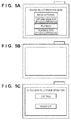
- the CPU 120 Upon being activated by the activation signal, the CPU 120, in step S121, first checks the result of battery authentication performed in step S103 by referencing the authentication information in the memory 124. If the authentication information indicates "successful battery authentication", processing proceeds from step S122 to step S125, and the CPU 120 displays a mode selection screen as shown in FIG. 5A on the display unit 122. The user can select a desired operation mode from the mode selection screen by operating the operation unit 123. Thereafter, the CPU 120 causes the imaging apparatus 100 to transition to the selected operation mode.
- step S126 the CPU 120 stops operating, and transitions to the power OFF state. In this way, in the case of "genuine product and unsuccessful battery authentication", the CPU 120 is turned OFF immediately after the battery authentication result has been checked. Therefore, nothing is displayed on the display unit 122 as shown in FIG. 5B . It is acceptable that the activation signal is not output in step S206 if the battery authentication result stored in the ROM 213 in step S203 indicates "genuine product and unsuccessful battery authentication". If this is the case, the external apparatus cannot activate the imaging apparatus 100, and the power button is operated to activate (power ON) the imaging apparatus 100. If the imaging apparatus 100 is thus activated, the imaging apparatus 100 displays a warning indicating "genuine product and unsuccessful battery authentication" for a predetermined period of time, and transitions to the power OFF state.
- step S124 the CPU 120 displays an operation instruction input screen as shown in FIG. 5C on the display unit 122, and waits until the user inputs an instruction to continue the operation or power OFF.
- the user operates the operation unit 123 of the imaging apparatus 100 to select whether to continue the operation of the imaging apparatus 100 or power OFF the imaging apparatus 100 and stop the operation.
- step S124 the CPU 120 displays an operation mode selection screen as shown in FIG. 5A on the display unit 122, and transitions to the operation mode specified by the user.
- step S124 determines "power OFF”
- the authentication result of the battery inserted into an apparatus is displayed on the display unit of its opposing apparatus, and the battery authentication result of the apparatus can be checked on the opposing apparatus.
- convenience is improved.
- the following describes a wireless terminal apparatus according to a second embodiment of the present invention with reference to FIGS. 6A to 7F . Since the basic configuration is the same as that of the first embodiment, the following mainly describes differences from the first embodiment.
- a description has been given of a configuration in which the battery authentication result of the imaging apparatus 100 can be checked on the mobile terminal 300 that has requested for connection to the imaging apparatus 100.
- the second embodiment makes it possible to check the authentication result of the battery 118 inserted into the imaging apparatus 100 on the display unit 322 of the mobile terminal 300, which is the opposing apparatus, and also provides a user interface for allowing the user to specify the operation mode when the imaging apparatus 100 is activated.
- the operation mode of the imaging apparatus 100 can be selected on the mobile terminal 300, and convenience is further improved.
- FIGS. 6A to 6D are flowcharts illustrating operations of the imaging apparatus 100 and the mobile terminal 300 according to the second embodiment. Note that steps for performing the same processing as in the first embodiment are indicated by the same step numbers as in the first embodiment ( FIGS. 3A to 3D ).
- FIGS. 7A to 7F show examples of screens displayed on the display unit 322 of the mobile terminal 300. The following provides a description with reference to the flowcharts shown in FIGS. 6A to 6D and the examples of screens shown in FIGS. 7A to 7F .
- the CPU 320 of the mobile terminal 300 Upon establishing a connection for wireless communication between the mobile terminal 300 and the imaging apparatus 100 (steps S207 and S303), the CPU 320 of the mobile terminal 300, in step S304, receives the battery authentication result transmitted by the imaging apparatus 100. Thereafter, the CPU 320 displays a screen corresponding to the received battery authentication result, on the display unit 322.
- step S305 if the battery authentication result indicates "successful battery authentication", processing proceeds from step S305 to step S306a, and the CPU 320 displays information indicating successful battery authentication on the display unit 322 as shown in FIG. 7A . Thereafter, processing proceeds from step S306a to step S306b, and the CPU 320 displays a screen for allowing the user to select an operation mode of the imaging apparatus 100 on the display unit 322 as shown in FIG. 7B , thereby prompting the user to select an operation mode of the imaging apparatus 100.
- the operation mode selected by the user on this operation mode selection screen is transmitted to the imaging apparatus 100 in step S312 as an operation mode selection signal.
- the user can provide an instruction regarding the operation at the time of activation to the imaging apparatus 100 from the mobile terminal 300.
- step S308a the CPU 320 displays information indicating unsuccessful battery authentication on the display unit 322 as shown in FIG. 7C .
- step S308b the CPU 320 displays a warning message notifying the user of the need to replace the battery inserted into the imaging apparatus 100, on the display unit 322 ( FIG. 7D ). If this is the case, a power OFF instruction is set as the operation mode selection signal.
- the CPU 120 immediately transitions to the power OFF state upon receiving the operation mode selection signal.
- step S307 If the battery authentication result indicates "non-genuine product", processing proceeds from step S307 to step S309a, and the CPU 320 displays information indicating that the battery is not a genuine product on the display unit 322 as shown in FIG. 7E . Thereafter, in step S309b, the CPU 320 displays a screen for allowing the user to select an operation of the imaging apparatus 100 (whether to “continue” the operation or “power OFF") on the display unit 322 as shown in FIG. 7F . If “continue” is selected, processing proceeds from step S310 to step S311, and the CPU 320 displays a screen for allowing the user to select an operation mode of the imaging apparatus 100 on the display unit 322 as shown in FIG.
- step S306b thereby prompting the user to select an operation mode.
- step S306b the selected operation mode is set to the operation mode selection signal, and processing proceeds to step S312.
- step S312 If "power OFF" is selected on the screen shown in FIG. 7F , a power OFF instruction is set to the operation mode selection signal, and processing proceeds to step S312.
- the CPU 320 transmits the operation mode selection signal indicating the operation mode selected on the mobile terminal 300 or the power OFF instruction to the imaging apparatus 100 via the wireless communication unit 321.
- step S211 upon receiving the operation mode selection signal transmitted from the wireless communication unit 321 of the mobile terminal 300, the wireless communication unit 121 of the imaging apparatus 100 transmits the operation mode selection signal to the CPU 120.
- the CPU 120 is activated by the activation signal transmitted from the wireless communication unit 121 in step S206 (step S120), and waits until the operation mode selection signal from the mobile terminal 300 is received (step S131). Then, upon receiving the operation mode selection signal from the wireless communication unit 121 in step S211, the CPU 120 transitions to the operation mode indicated by the operation mode selection signal.
- the imaging apparatus 100 transitions to the operation mode selected on the mobile terminal 300, which is the opposing apparatus.
- step S131 If the received operation mode selection signal indicates that the operation mode has not been selected, or if the CPU 120 does not receive the operation mode selection signal when a predetermined period of time has elapsed since the activation of the CPU 120, processing proceeds from step S131 to S121. In steps S121 to S128, as described in the first embodiment, an operation mode or the power OFF instruction is selected on the imaging apparatus 100.
- the second embodiment makes it possible to check the authentication result of the battery 118 inserted into the imaging apparatus 100 on the display unit 322 of the mobile terminal 300, which is the opposing apparatus, and furthermore, makes it possible to select the operation mode of the imaging apparatus 100 on the mobile terminal 300. Therefore, it is possible to improve convenience.
- the following describes an imaging apparatus according to a third embodiment with reference to FIGS. 8 and 9A to 9C . Since the basic configuration is the same as that of the second embodiment, the following mainly describes differences from the second embodiment.
- a description is given of a configuration in which standby power of the imaging apparatus 100 is reduced by switching the activation operation of the CPU 120 of the imaging apparatus 100 according to the operation mode of the imaging apparatus 100 selected on the mobile terminal 300, which is the opposing apparatus.
- FIG. 8 shows a flowchart illustrating the operations of the imaging apparatus 100 according to the third embodiment.
- the following describes the operations of the imaging apparatus 100 according to the third embodiment with reference to the flowchart shown in FIG. 8 .
- steps for performing the same processing as in the second embodiment are indicated by the same step numbers.
- the operations of the mobile terminal 300 are the same as those in the second embodiment ( FIG. 6D ), and therefore the operations are omitted from the drawing.
- step S302 Upon the request signal being transmitted from the mobile terminal 300 (step S302) and being received by the wireless communication control unit 210 (YES in step S205), processing proceeds to step S207, and mutual connection between the imaging apparatus 100 and the mobile terminal 300 is established. At this time, the activation signal is not output to the CPU 120, and the CPU 120 still remains in the stopped state (the power OFF state).
- the wireless communication unit 121 of the imaging apparatus 100 receives the operation mode selection signal in step S211.
- the wireless communication unit 121 transmits the received operation mode selection signal to the CPU 120 as the activation signal.
- the CPU 120 thus receives the activation signal and the operation mode selection signal from the wireless communication unit 121 at the same time.
- the CPU 120 Upon the information control unit 191 of the imaging apparatus 100 receiving the activation signal, the CPU 120 is activated in step S120. Upon being activated, the CPU 120 immediately determines the operation mode indicated by the operation mode selection signal transmitted as the activation signal, and transitions to the operation mode indicated by the operation mode selection signal (step S141). In this way, in the third embodiment, the CPU 120 is not activated until an operation mode is selected on the mobile terminal 300 and the imaging apparatus 100 receives the operation mode selection signal, and therefore the standby power of the imaging apparatus 100 can be reduced.
- step S211 it is acceptable that the wireless communication unit 121 does not transmit the operation mode selection signal (the activation signal) to the CPU 120 if the operation mode selection signal indicates "power OFF". If this is the case, it is possible to prevent the CPU 120 from being activated despite the power OFF instruction and then immediately transiting to the power OFF state.
- FIGS. 9A to 9C are diagrams showing examples of screens displayed on the display unit 122 of the imaging apparatus 100 according to the third embodiment.
- the CPU 120 Before the CPU 120 is activated, nothing is displayed on the display unit 122 as shown in FIG. 9A because the power of the CPU 120 is OFF. It is assumed that thereafter an operation mode is selected on the mobile terminal 300 (step S306b and step S311), the operation mode selection signal is transmitted (step S312), and the CPU 120 is activated. If this is the case, as shown in FIG. 9B , the CPU 120 displays information indicating that the CPU 120 is about to transition to the operation mode specified by the operation mode selection signal received by the wireless communication unit 121, on the display unit 122.
- the operation mode selection signal transmitted from the wireless communication unit 121 indicates power OFF, or the operation mode selection signal is not transmitted from the wireless communication unit 121. Therefore, the CPU 120 immediately stops operating (enters the power OFF state) after being activated, or is not activated. Therefore, as shown in FIG. 9C , the screen remains in the state of showing nothing.
- the operation to activate the CPU 120 of the imaging apparatus 100 is switched according to the operation mode selected on the mobile terminal 300, which is the opposing apparatus. Therefore, it is possible to reduce the standby power of the imaging apparatus 100.
- FIG. 10 is a flowchart illustrating operations of the imaging apparatus 100 according to the fourth embodiment.
- the operations of the mobile terminal 300 are the same as those in the second embodiment ( FIG. 6D ).
- the user inserts the battery 118, which serves as the main battery, into the imaging apparatus 100.
- the CPU 120 Upon the battery 118 being inserted, power is supplied from the battery 118 to both the main-board and the sub-board, the CPU 120 is activated, and also the wireless communication control unit 210 on the sub-board is activated in step S201.
- the CPU 120 reads out a control program (a driver) for the wireless communication control unit 210 from the memory 124, and transmits the control program to the information control unit 212 in the wireless communication control unit 210 via the information control unit 191. Thereafter, the CPU 120 stops operating (enters the power OFF state), and waits until the CPU 120 is powered ON by receiving the activation signal from the wireless communication unit 121 or by the user operating the power button.
- a control program a driver
- step S202 the wireless communication control unit 210 loads the control program received by the information control unit 212 to the RAM 214, and starts a wireless communication operation by executing the control program. Thereafter, the wireless communication control unit 210 starts outputting the beacon signal in step S204.
- the battery authentication has not been executed at this time.
- the CPU 320 activates the application in step S301.
- the CPU 320 transmits the request signal for activating the imaging apparatus 100 to the imaging apparatus 100 via the wireless communication unit 321.
- step S205 the wireless communication unit 121 receives the request signal transmitted from the mobile terminal 300.
- processing proceeds from step S205 to step S221.
- step S221 the wireless communication control unit 210 transmits a signal for activating a system (the activation signal) to the information control unit 191 of the CPU 120 of the imaging apparatus 100 via the information control unit 212.
- the CPU 120 of the imaging apparatus 100 is activated, and the CPU 120 executes battery authentication, records the authentication result, and notifies the wireless communication unit 121 of the authentication result (steps S103 to S106). Thereafter, the CPU 120 stops operating again (power OFF).
- the information control unit 212 Upon receiving the battery authentication result, the information control unit 212 stores the received battery authentication result in the ROM 213 in step S203.
- the subsequent operations of the imaging apparatus 100 steps S207, S208, S211, S120, and S141
- the subsequent operations of the mobile terminal 300 are the same as those in the third embodiment. Note that if the user turns ON the power by operating the power button before the CPU 120 receives the activation signal from the wireless communication unit 121, the CPU 120 is immediately activated, and processing in step S103 and the subsequent steps is executed, followed by execution of the operations according to steps S121 to S128 in the first embodiment ( FIG. 3B ).
- the operation to activate the CPU 120 is switched according to the operation mode selected on the mobile terminal 300, which is the opposing apparatus. Therefore, it is unnecessary for the CPU 120 of the imaging apparatus 100 to wait in the activated state until an operation mode is selected on the mobile terminal 300, and it is possible to reduce the standby power.
- the imaging apparatus 100 and the mobile terminal 300 according to the fifth embodiment.
- the basic configuration is the same as those of the first to fourth embodiments.
- the standby power of the imaging apparatus 100 is reduced by switching the CPU activation operation according to the operation mode of the imaging apparatus 100 selected on the mobile terminal 300.
- power supply to the main-board and the sub-board is started upon detecting that a battery lid, which covers the battery 118, is closed.
- FIG. 11A is a flowchart illustrating operations of the imaging apparatus 100 according to the fifth embodiment
- FIG. 11B is a flowchart illustrating operations of the mobile terminal 300 according to the fifth embodiment
- FIG. 12 is a diagram showing an example of a screen displayed by the mobile terminal 300 according to the fifth embodiment.
- step S101 the user inserts the battery 118 into the imaging apparatus 100.
- step S113 the battery lid detection unit 114 checks whether or not the battery lid has been closed. If the battery lid detection unit 114 confirms that the battery lid has been closed (YES in step S113), power is supplied from the battery 118, which serves as the main battery, to both the main-board and the sub-board.
- the battery lid detection unit 114 can be realized as a switch that connects the battery 118 to a power line between the main-board and the battery 118 and to a power line between the sub-board and the battery 118 when the battery lid is closed.
- Steps S102 to S106 are the same as those in the first embodiment ( FIG. 3A ). Meanwhile, upon the wireless communication control unit 210 being activated in step S201 due to power being supplied to the sub-board, steps S202 to S211 are executed. Steps S202 to S211 are the same as those in the third embodiment ( FIG. 8 ).
- the mobile terminal 300 which is the opposing apparatus, upon an application that has the function of communicating with the imaging apparatus 100 being activated, and receiving, from the user, an instruction to start communication, the mobile terminal 300 transmits the request signal to the imaging apparatus 100, and connects to the imaging apparatus 100. Thereafter, upon receiving a notification regarding the battery authentication result, the mobile terminal 300 displays a screen as shown in FIGS. 7A to 7F according to the battery authentication result thus received, and prompts the user to select an operation mode.
- the above-described processing is the processing shown in steps S301 to S312 of FIG. 11B , and is the same as that in the second embodiment ( FIG. 6D ).
- the mobile terminal 300 in the fifth embodiment determines whether or not "power OFF" has been set to the operation mode selection signal in step S313. If “power OFF” has not been set, processing immediately ends. If “power OFF” has been set, processing proceeds to step S314. As described in the second embodiment above, cases in which "power OFF" is set as the operation mode selection signal are:
- step S314 the CPU 320 displays a screen for prompting the user to select whether or not to stop the beacon signal from the imaging apparatus 100, on the display unit 322.
- FIG. 12 is an example of such a screen for prompting the user to select whether to stop or continue outputting the beacon signal.
- the CPU 320 transmits an instruction to stop the beacon signal to the wireless communication unit 121 of the imaging apparatus 100 via the wireless communication unit 321 in step S315.
- the wireless communication control unit 210 stops outputting the beacon signal upon receiving the instruction to stop the beacon signal from the mobile terminal 300 (step S231).
- processing immediately ends after step S314.
- the standby power of the imaging apparatus 100 is reduced by switching the activation operation of the CPU 320 according to the operation mode of the imaging apparatus 100 selected on the opposing apparatus. Also, it is possible to stop the beacon signal from the wireless communication unit 121 if the battery authentication result indicates a non-genuine product, or if an instruction to power OFF the imaging apparatus 100 is given from the mobile terminal 300, or if the battery authentication result indicates a genuine product and the authentication failed. Therefore, it is possible to prevent the imaging apparatus 100 from transmitting an unnecessary beacon signal, and to further save power.
- the result of battery authentication in an electronic device can be checked on another electronic device that serves as the opposing apparatus in terms of wireless communication, and thus user convenience can be improved.
- Embodiment(s) of the present invention can also be realized by a computer of a system or apparatus that reads out and executes computer executable instructions (e.g., one or more programs) recorded on a storage medium (which may also be referred to more fully as a 'non-transitory computer-readable storage medium') to perform the functions of one or more of the above-described embodiment(s) and/or that includes one or more circuits (e.g., application specific integrated circuit (ASIC)) for performing the functions of one or more of the above-described embodiment(s), and by a method performed by the computer of the system or apparatus by, for example, reading out and executing the computer executable instructions from the storage medium to perform the functions of one or more of the above-described embodiment(s) and/or controlling the one or more circuits to perform the functions of one or more of the above-described embodiment(s).
- computer executable instructions e.g., one or more programs
- a storage medium which may also be referred to more fully as
- the computer may comprise one or more processors (e.g., central processing unit (CPU), micro processing unit (MPU)) and may include a network of separate computers or separate processors to read out and execute the computer executable instructions.
- the computer executable instructions may be provided to the computer, for example, from a network or the storage medium.
- the storage medium may include, for example, one or more of a hard disk, a random-access memory (RAM), a read only memory (ROM), a storage of distributed computing systems, an optical disk (such as a compact disc (CD), digital versatile disc (DVD), or Blu-ray Disc (BD)TM), a flash memory device, a memory card, and the like.
Landscapes
- Engineering & Computer Science (AREA)
- Theoretical Computer Science (AREA)
- Computer Security & Cryptography (AREA)
- Physics & Mathematics (AREA)
- General Physics & Mathematics (AREA)
- Computer Hardware Design (AREA)
- Software Systems (AREA)
- General Engineering & Computer Science (AREA)
- Computer Networks & Wireless Communication (AREA)
- Signal Processing (AREA)
- Electromagnetism (AREA)
- Medical Informatics (AREA)
- General Health & Medical Sciences (AREA)
- Computing Systems (AREA)
- Multimedia (AREA)
- Health & Medical Sciences (AREA)
- Telephone Function (AREA)
- Studio Devices (AREA)
- Remote Monitoring And Control Of Power-Distribution Networks (AREA)
- Charge And Discharge Circuits For Batteries Or The Like (AREA)
- Secondary Cells (AREA)
- Selective Calling Equipment (AREA)
- Mobile Radio Communication Systems (AREA)
Abstract
Description
- The present invention relates to a communication apparatus and a method for controlling the communication apparatus.
- Imaging apparatuses such as digital cameras include an imaging apparatus that is provided with a battery authentication function in order to guarantee that the image apparatus properly operates. An imaging apparatus having a battery authentication function performs authentication in order to determine whether or not a battery that has been inserted into the imaging apparatus is a battery that has been guaranteed to properly operate by the manufacturer. Specifically, upon a battery being inserted into the imaging apparatus by a user, authentication of the inserted battery is performed within the imaging apparatus. The authentication result of the battery is displayed on a display unit of the imaging apparatus, and the user is thus informed of the authentication result. Therefore, the user can check the authentication result thus displayed, and set the subsequent operations of the imaging apparatus.
- Imaging apparatuses such as digital cameras also include an imaging apparatus that is provided with a wireless communication function such as Bluetooth (TM) and a wireless LAN, in order to share various kinds of data with another imaging apparatus. This function enables the imaging apparatuses to transmit and receive various kinds of data such as image data to and from each other, without passing through a PC therebetween. Also, using the wireless communication function, it is possible to operate the imaging apparatus from a remote electronic device such as a mobile terminal.
- Technology for improving user convenience, such as methods for informing a user of an authentication result or various kinds of data after the authentication has been performed, have been proposed for various authentication systems for electronic devices provided with a wireless communication function other than imaging apparatuses. For example,
Japanese Patent Laid-Open No. 2009-203641 Document 1") discloses an electronic key system with which, at a time of battery exhaustion of an electronic key, a user can assuredly be aware of that, and immediately restore an on-board apparatus to a controllable state. Also,Japanese Patent Laid-Open No. 2008-141555 Document 2") discloses that in an apparatus provided with a function realizing means for realizing functions including a call originating/receiving function, restrictions on the functions of the function realizing means are lifted when information read out from a wireless IC tag provided for a mobile authentication key and information registered to the apparatus match each other. - As described above, an imaging apparatus having a wireless communication function can be activated from a remote electronic device, using wireless communication. However, even if the imaging apparatus has the battery authentication function, the user can check the result of battery authentication only on the imaging apparatus. Therefore, when activating the imaging apparatus by using an electronic device from a place that is remote from the imaging apparatus, the user cannot obtain the result of battery authentication. This is inconvenient for the user.
- The present invention has been made in view of the above-described problem, and provides an electronic device and a control method thereof that make it possible to check the result of battery authentication for the electronic device on another electronic device that is an opposing apparatus in terms of wireless communication.
- The present invention in a first aspect provides a communication apparatus as specified in
claims 1 to 11. - The present invention in a second aspect provides a method for controlling a communication apparatus as specified in
claim 12. - The present invention in a third aspect provides a program as specified in
claim 13. - Further features of the present invention will become apparent from the following description of embodiments (with reference to the attached drawings).
-
-
FIG. 1A is a block diagram showing an example of a configuration of an imaging apparatus according to an embodiment. -
FIG. 1B is a block diagram showing an example of a configuration of a mobile terminal according to the embodiment. -
FIG. 1C is a diagram showing a system configured with the imaging apparatus and the mobile terminal according to the embodiment. -
FIG. 2 is a diagram illustrating a configuration related to wireless communication performed within the imaging apparatus according to the embodiment. -
FIGs. 3A to 3C are flowcharts illustrating operations of an imaging apparatus according to a first embodiment. -
FIG. 3D is a flowchart illustrating operations of a mobile terminal according to the first embodiment. -
FIGS. 4A to 4C are diagrams showing examples of content displayed by the mobile terminal according to the first embodiment. -
FIGS. 5A to 5C are diagrams showing examples of content displayed by the imaging apparatus according to the first embodiment. -
FIGs. 6A to 6C are flowcharts illustrating operations of an imaging apparatus according to a second embodiment. -
FIG. 6D is a flowchart illustrating operations of a mobile terminal according to the second embodiment. -
FIGS. 7A to 7F are diagrams showing examples of content displayed by the mobile terminal according to the second embodiment. -
FIG. 8 is a flowchart illustrating operations of an imaging apparatus according to a third embodiment. -
FIGS. 9A to 9C are diagrams showing examples of content displayed by the imaging apparatus according to the third embodiment. -
FIG. 10 is a flowchart illustrating operations of an imaging apparatus according to a fourth embodiment. -
FIG. 11A is a flowchart illustrating operations of an imaging apparatus according to a fifth embodiment. -
FIG. 11B is a flowchart illustrating operations of a mobile terminal according to the fifth embodiment. -
FIG. 12 is a diagram showing an example of content displayed by the mobile terminal according to the fifth embodiment. - The following describes preferred embodiments of the present invention in detail with reference to the accompanying drawings.
- The following describes a wireless terminal apparatus according to a first embodiment with reference to
FIGS. 1A to 1C ,2 ,3A and3B ,4A to 4C , and5A to 5C .FIG. 1A is a block diagram showing a configuration of an imaging apparatus, which is an example of an electronic device (wireless terminal apparatus) provided with a battery authentication function according to the first embodiment.FIG. 1B is a block diagram showing a configuration of a mobile terminal, which is an example of an electronic device (wireless terminal apparatus) serving as a communication party apparatus (opposing apparatus) for the imaging apparatus.FIG. 1C shows a configuration of a communication system according to the first embodiment. - As shown in
FIG. 1C , the communication system according to the present embodiment includes animaging apparatus 100 and amobile terminal 300 connected to each other via wireless communication, for example. Theimaging apparatus 100 is an example of an electronic device that can be driven with a battery and that performs battery authentication. Themobile terminal 300 is an example of an electronic device that is connected to theimaging apparatus 100, which is an external apparatus, using wireless communication. - First, a configuration of the
imaging apparatus 100 is described with reference toFIG. 1A . Anoptical unit 101 is provided with a zoom lens, a focus lens, and an aperture, as well as a motor, an actuator, and a drive circuit that drive the zoom lens, the focus lens, and the aperture. Animaging device 102 performs photoelectric conversion by forming an image of light from a subject, on a light-receiving surface thereof. Animaging driver 103 drives theimaging device 102 and causes theimaging device 102 to transfer the electric charge of each pixel resulting from the photoelectric conversion, thereby causing theimaging device 102 to output a captured-image signal. Anamplifier 104 amplifies the captured-image signal output from theimaging device 102, after removing noise therefrom by performing correlated double sampling. An A/D converter 105 generates image data by performing digital conversion on the captured-image signal amplified by theamplifier 104. - An image
data processing circuit 106 applies various kinds of image processing, such as matrix operations, white balance adjustment, and gamma processing, to the input image data. Aframe memory 107 temporarily stores image data processed by the imagedata processing circuit 106. A compression/decompression processing circuit 108 compresses or decompresses image data, using theframe memory 107. Amemory card 109 records an image file thereon. A read/write (R/W)circuit 110 writes or reads out an image file compressed by the compression/decompression processing circuit 108 to or from thememory card 109. An imagefeature extraction circuit 116 extracts a feature of image information. A pixelsensitivity calculation circuit 117 calculates appropriate sensitivity for each pixel of image information obtained by theimaging device 102. - An autofocus circuit (hereinafter, "
AF circuit 111") detects the focal distance based on image data corresponding to a ranging area stored in theframe memory 107. An automatic exposure circuit (hereinafter, "AE circuit 112") measures subject brightness based on image data corresponding to a ranging area stored in theframe memory 107, and obtains an aperture value, an exposure time, and an exposure condition that indicates whether or not to fire the electronic flash, which is not shown in the drawings, by performing calculation based on a photometric value. An automatic white balance circuit (hereinafter, "AWB circuit 113") automatically adjusts the white balance at the time of image capturing. - A
battery 118 can be attached to and removed from theimaging apparatus 100, and supplies power to each unit of theimaging apparatus 100 while being attached to theimaging apparatus 100. Abattery authentication unit 115 communicates with thebattery 118 attached to theimaging apparatus 100, and performs battery authentication. A batterylid detection unit 114 detects that a lid (not shown in the drawings) of a battery housing box, into which thebattery 118 is to be inserted, is open or closed. An example of communication between thebattery authentication unit 115 and thebattery 118 is serial communication. The authentication result of thebattery 118 is stored in amemory 124, for example. During battery authentication, the manufacturer, the type, the serial number, and so on of the battery that has been inserted are checked. - A
CPU 120 realizes various kinds of control for theimaging apparatus 100 by executing programs stored in thememory 124, for example. Awireless communication unit 121 performs control to transmit and receive various kinds of data such as image data to and from an external apparatus. Thewireless communication unit 121 transmits and receives various kinds of data and so on to and from an external apparatus, which is an opposing apparatus in terms of wireless communication, based on terminal information stored in thememory 124 for example. - A
display unit 122 is configured with a liquid crystal display device for example, and displays a playback image, and when in an image capturing mode, functions as an electronic viewfinder as well by displaying a through-the-lens image used for checking a subject. Anoperation unit 123 includes a power button, a release button, a mode switching dial, and so on. Thememory 124 records thereon setting values relating to exposure, such as an aperture value and a shutter speed, and terminal information or the like used for wireless communication. Programs to be executed by theCPU 120 may be stored in thememory 124, as described above. -
FIG. 1B is a block diagram showing a configuration of themobile terminal 300, which is an example of an electronic device that serves as an opposing apparatus for theimaging apparatus 100. In themobile terminal 300, aCPU 320 realizes various kinds of operations of themobile terminal 300 by executing programs stored in amemory 324, for example. Awireless communication unit 321 realizes wireless communication with an external apparatus (e.g. the imaging apparatus 100). Adisplay unit 322 is configured with a liquid crystal display device for example, and displays various kinds of information regarding themobile terminal 300 under the control of theCPU 320. Anoperation unit 323 receives a user operation and provides theCPU 320 with an operation signal. Theoperation unit 323 may be configured with a touch panel or the like. Thememory 324 stores programs to be executed by theCPU 320 and various kinds of data, and also provides a work area for theCPU 320. - In
FIGS. 1A ,1B, and 1C , a digital camera (the imaging apparatus 100) is described as an example of the wireless terminal apparatus. However, the present invention is not limited in such a manner. For example, the wireless terminal apparatus may be any electronic device such as a smartphone as long as it can be driven with a battery and has the battery authentication function and the wireless communication function. Also, although a mobile terminal has been described as an example of the opposing apparatus for theimaging apparatus 100, the present invention is not limited in such a manner. The opposing apparatus may be any electronic device as long as it has the wireless communication function. Of course, the opposing apparatus is not necessarily of a mobile type. - Next, the details of the
CPU 120, thebattery authentication unit 115, and thewireless communication unit 121 of theimaging apparatus 100 will be described with reference toFIG. 2 . In theimaging apparatus 100, theCPU 120 and thebattery authentication unit 115 are mounted on a main-board, and thewireless communication unit 121 is mounted on a sub-board. The main-board and the sub-board are connected to each other via a flexible board or the like. TheCPU 120 on the main-board is provided with aninformation control unit 191 for connecting to thewireless communication unit 121 and transmitting and receiving various kinds of information such as the battery authentication result to and from thewireless communication unit 121. - The
wireless communication unit 121 on the sub-board is provided with: a wirelesscommunication control unit 210 for controlling communication with theinformation control unit 191 on the main-board and controlling wireless communication with the opposing apparatus (e.g. the mobile terminal 300); and anantenna unit 211 for transmitting and receiving a wireless signal to and from the opposing apparatus. In the present embodiment, a Bluetooth (TM) communication method is used by the wirelesscommunication control unit 210, for example. Theantenna unit 211 is a chip antenna or a pattern antenna, for example. - The wireless
communication control unit 210 is provided with aninformation control unit 212 for transmitting and receiving various kinds of information such as the battery authentication result to and from theinformation control unit 191. Communication between theinformation control unit 191 and theinformation control unit 212 is controlled using serial communication, for example. Furthermore, aROM 213 and aRAM 214 are connected to the wirelesscommunication control unit 210. TheROM 213 is for storing various kinds of information regarding thewireless communication unit 121, and theRAM 214 is for temporarily storing information loaded thereto, namely various kinds of information received by theinformation control unit 212, and information stored in theROM 213. - Power (VBAT) is supplied from the
battery 118, which is the main battery, to both the main-board and the sub-board so that the main-board and the sub-board can each operate independently. Note that the configurations above are examples. The configurations are not limited to the description above, and may be modified as appropriate. For example, the antenna is not necessarily provided on thewireless communication unit 121, and may be located at a place that is not on thewireless communication unit 121, by extending the antenna line using a lead wire. -
FIGs. 3A to 3C show a flowchart illustrating the operations of theimaging apparatus 100 according to the first embodiment, andFIG. 3D shows a flowchart illustrating the operations of themobile terminal 300 according to the first embodiment. The following describes the operations of theimaging apparatus 100 and themobile terminal 300 according to the first embodiment (in particular, the operation by which themobile terminal 300 activates the imaging apparatus 100) with reference to the flowchart shown inFIGS. 3A to 3D . - In step S101, a user inserts the
battery 118, which serves as the main battery, into theimaging apparatus 100. Upon thebattery 118 being inserted, power is supplied from thebattery 118 to both the main-board and the sub-board, theCPU 120 is activated, and also the wirelesscommunication control unit 210 on the sub-board is activated in step S201. In step S102, theCPU 120 reads out a control program (a driver) for the wirelesscommunication control unit 210 from thememory 124, and transmits the control program to theinformation control unit 212 in the wirelesscommunication control unit 210 via theinformation control unit 191. In step S103, thebattery authentication unit 115 communicates with thebattery 118, and performs authentication (battery authentication) of thebattery 118 that has been inserted. In step S202, the wirelesscommunication control unit 210 loads the control program received by theinformation control unit 212 to theRAM 214, and starts a wireless communication operation by executing the control program. - In step S104, the
CPU 120 checks the authentication result of thebattery 118 performed by thebattery authentication unit 115 in step S103. If the battery authentication is unsuccessful (NO in step S104), processing proceeds to step S105, and theCPU 120 updates the battery authentication information in thememory 124. If the battery authentication is successful (YES in step S104), processing proceeds to step S106. In step S106, theCPU 120 notifies thewireless communication unit 121 of the battery authentication result via theinformation control unit 191. Note that the battery authentication result includes information regarding whether or not the battery authentication was successful and information regarding whether or not the battery is a genuine product. - Although the battery authentication information is stored in the
memory 124 of theimaging apparatus 100 in the present embodiment, the battery authentication information may be stored in a flip-flop or the like separately provided to store the battery authentication information, for example. Also, although the authentication result in thememory 124 is updated when the battery authentication is unsuccessful in the flowchart above, the authentication result may be updated when the battery authentication is successful, or both the successful state and the unsuccessful state may be recorded as the authentication information. Thereafter, theCPU 120 stops operating and enters a power OFF state, and maintains this state until the user operates the power button or theCPU 120 receives an activation signal from thewireless communication unit 121. - In step S203, the wireless
communication control unit 210 on the sub-board stores the battery authentication result received by theinformation control unit 212 to theROM 213. In step S204, the wirelesscommunication control unit 210 starts outputting a beacon signal, and in step S205, enters the state of waiting to receive a request signal from the opposing apparatus, which is an external apparatus. - In the
mobile terminal 300, which is the opposing apparatus, when the user activates an application for communication with theimaging apparatus 100, an activation process for theimaging apparatus 100 as shown inFIG. 3D is executed. In step S301, theCPU 320 activates the application. The application thus activated can receive a user instruction to start communication with theimaging apparatus 100. In response to the application being activated, or upon receiving the user instruction to start communication with theimaging apparatus 100 after the application is activated, theCPU 320, in step S302, transmits a request signal to theimaging apparatus 100 via thewireless communication unit 321. Note that theCPU 320 transmits the request signal in response to the beacon signal received from theimaging apparatus 100, and consequently procedures for starting communication (connection) with theimaging apparatus 100 are executed. When in the power OFF state, theimaging apparatus 100 enters a power ON state upon receiving the request signal, and is activated. - In step S205, the wireless
communication control unit 210 of theimaging apparatus 100 determines whether or not the request signal transmitted from themobile terminal 300 has been received. Upon thewireless communication unit 121 of theimaging apparatus 100 receiving the request signal transmitted from thewireless communication unit 321 of themobile terminal 300, which is the opposing apparatus (YES in step S205), processing proceeds to step S206. In step S206, the wirelesscommunication control unit 210 transmits a signal for activating a system (an activation signal) to theinformation control unit 191 of theCPU 120 via theinformation control unit 212. - Thereafter, in steps S207 and S303, the
wireless communication unit 121 of theimaging apparatus 100, and thewireless communication unit 321 of themobile terminal 300, which has transmitted the request signal, establish connection for mutual wireless communication. Upon establishment of a connection for wireless communication, in step S208, the wirelesscommunication control unit 210 transmits the battery authentication result stored in theROM 213 to themobile terminal 300, which is the opposing apparatus. Thus, in response to receiving the request, theCPU 120 transmits the result of authentication by thebattery authentication unit 115 to themobile terminal 300, which is an external apparatus, via thewireless communication unit 121. Note that in battery authentication in the present embodiment, whether or not the attached battery is a genuine product is checked, and the result of authentication is included in the battery authentication result. In the present embodiment, if battery authentication is successful, the battery is always a genuine product. It is assumed that if battery authentication is unsuccessful, the battery can be a genuine product or a non-genuine product. An example of this case is a case in which authentication cannot be complete even though the manufacturer of the battery has been verified. Therefore, in the present embodiment, there are three possible battery authentication results, namely "successful battery authentication", "genuine product and unsuccessful battery authentication", and "non-genuine product". - In the
mobile terminal 300, upon establishing a connection for wireless communication (step S303), theCPU 320, in step S304, receives the battery authentication result transmitted by theimaging apparatus 100. Then, theCPU 320 executes display control to display a screen corresponding to the received battery authentication result, on the display unit 322 (step S305 to step S309). The content to be displayed on thedisplay unit 322 of themobile terminal 300, which is the opposing apparatus for theimaging apparatus 100, are described below with reference toFIGS. 4A to 4C . If the battery authentication result indicates "successful battery authentication", processing proceeds from step S305 to step S306. In step S306, theCPU 320 of themobile terminal 300 displays information indicating that battery authentication was successful on thedisplay unit 322 as shown inFIG. 4A , thereby prompting the user to select an operation, using theimaging apparatus 100. If the battery authentication result indicates "genuine product and unsuccessful battery authentication", processing proceeds from step S307 to step S308. In step S308, theCPU 320 of themobile terminal 300 displays information indicating that battery authentication failed on thedisplay unit 322 as shown inFIG. 4B , thereby prompting the user to replace the battery inserted into theimaging apparatus 100. If the battery authentication result indicates "non-genuine product", processing proceeds from step S307 to step S309. In step S307, theCPU 320 displays information indicating that the battery is not a genuine product on thedisplay unit 322 as shown inFIG. 4C , thereby prompting the user to select an operation, using theimaging apparatus 100. - Meanwhile, upon the
information control unit 191 receiving the activation signal transmitted from thewireless communication unit 121 in step S206, activation control for theCPU 120 is executed (step S120). In activation control, theimaging apparatus 100 is activated upon receipt of the request from themobile terminal 300, and theimaging apparatus 100 operates based on the battery authentication result. The following describes activation control for theimaging apparatus 100 according to the present embodiment. Upon being activated by the activation signal, theCPU 120, in step S121, first checks the result of battery authentication performed in step S103 by referencing the authentication information in thememory 124. If the authentication information indicates "successful battery authentication", processing proceeds from step S122 to step S125, and theCPU 120 displays a mode selection screen as shown inFIG. 5A on thedisplay unit 122. The user can select a desired operation mode from the mode selection screen by operating theoperation unit 123. Thereafter, theCPU 120 causes theimaging apparatus 100 to transition to the selected operation mode. - If the authentication information indicates "genuine product and unsuccessful battery authentication", processing proceeds from step S123 to step S126 in order to execute a stopping operation. In step S126, the
CPU 120 stops operating, and transitions to the power OFF state. In this way, in the case of "genuine product and unsuccessful battery authentication", theCPU 120 is turned OFF immediately after the battery authentication result has been checked. Therefore, nothing is displayed on thedisplay unit 122 as shown inFIG. 5B . It is acceptable that the activation signal is not output in step S206 if the battery authentication result stored in theROM 213 in step S203 indicates "genuine product and unsuccessful battery authentication". If this is the case, the external apparatus cannot activate theimaging apparatus 100, and the power button is operated to activate (power ON) theimaging apparatus 100. If theimaging apparatus 100 is thus activated, theimaging apparatus 100 displays a warning indicating "genuine product and unsuccessful battery authentication" for a predetermined period of time, and transitions to the power OFF state. - If the authentication information indicates "non-genuine product", processing proceeds from step S123 to step S124. In step S124, the
CPU 120 displays an operation instruction input screen as shown inFIG. 5C on thedisplay unit 122, and waits until the user inputs an instruction to continue the operation or power OFF. The user operates theoperation unit 123 of theimaging apparatus 100 to select whether to continue the operation of theimaging apparatus 100 or power OFF theimaging apparatus 100 and stop the operation. If the user selects "continue", processing proceeds from step S124 to step S127, and theCPU 120 displays an operation mode selection screen as shown inFIG. 5A on thedisplay unit 122, and transitions to the operation mode specified by the user. On the other hand, if the user selects "power OFF", processing proceeds from step S124 to step S128, and causes theimaging apparatus 100 to transition to the power OFF state. - As described above, according to the first embodiment, the authentication result of the battery inserted into an apparatus is displayed on the display unit of its opposing apparatus, and the battery authentication result of the apparatus can be checked on the opposing apparatus. Thus, convenience is improved.
- The following describes a wireless terminal apparatus according to a second embodiment of the present invention with reference to
FIGS. 6A to 7F . Since the basic configuration is the same as that of the first embodiment, the following mainly describes differences from the first embodiment. In the first embodiment, a description has been given of a configuration in which the battery authentication result of theimaging apparatus 100 can be checked on themobile terminal 300 that has requested for connection to theimaging apparatus 100. The second embodiment makes it possible to check the authentication result of thebattery 118 inserted into theimaging apparatus 100 on thedisplay unit 322 of themobile terminal 300, which is the opposing apparatus, and also provides a user interface for allowing the user to specify the operation mode when theimaging apparatus 100 is activated. Thus, the operation mode of theimaging apparatus 100 can be selected on themobile terminal 300, and convenience is further improved. -
FIGS. 6A to 6D are flowcharts illustrating operations of theimaging apparatus 100 and themobile terminal 300 according to the second embodiment. Note that steps for performing the same processing as in the first embodiment are indicated by the same step numbers as in the first embodiment (FIGS. 3A to 3D ).FIGS. 7A to 7F show examples of screens displayed on thedisplay unit 322 of themobile terminal 300. The following provides a description with reference to the flowcharts shown inFIGS. 6A to 6D and the examples of screens shown inFIGS. 7A to 7F . - Upon establishing a connection for wireless communication between the
mobile terminal 300 and the imaging apparatus 100 (steps S207 and S303), theCPU 320 of themobile terminal 300, in step S304, receives the battery authentication result transmitted by theimaging apparatus 100. Thereafter, theCPU 320 displays a screen corresponding to the received battery authentication result, on thedisplay unit 322. - Specifically, if the battery authentication result indicates "successful battery authentication", processing proceeds from step S305 to step S306a, and the
CPU 320 displays information indicating successful battery authentication on thedisplay unit 322 as shown inFIG. 7A . Thereafter, processing proceeds from step S306a to step S306b, and theCPU 320 displays a screen for allowing the user to select an operation mode of theimaging apparatus 100 on thedisplay unit 322 as shown inFIG. 7B , thereby prompting the user to select an operation mode of theimaging apparatus 100. The operation mode selected by the user on this operation mode selection screen is transmitted to theimaging apparatus 100 in step S312 as an operation mode selection signal. Thus, the user can provide an instruction regarding the operation at the time of activation to theimaging apparatus 100 from themobile terminal 300. - If the battery authentication result indicates "genuine product and unsuccessful battery authentication", processing proceeds from step S307 to step S308a. In step S308a, the
CPU 320 displays information indicating unsuccessful battery authentication on thedisplay unit 322 as shown inFIG. 7C . Thereafter, in step S308b, theCPU 320 displays a warning message notifying the user of the need to replace the battery inserted into theimaging apparatus 100, on the display unit 322 (FIG. 7D ). If this is the case, a power OFF instruction is set as the operation mode selection signal. As a result, as described below, if the battery authentication result of thebattery 118 indicates "genuine product and unsuccessful battery authentication", theCPU 120 immediately transitions to the power OFF state upon receiving the operation mode selection signal. - If the battery authentication result indicates "non-genuine product", processing proceeds from step S307 to step S309a, and the
CPU 320 displays information indicating that the battery is not a genuine product on thedisplay unit 322 as shown inFIG. 7E . Thereafter, in step S309b, theCPU 320 displays a screen for allowing the user to select an operation of the imaging apparatus 100 (whether to "continue" the operation or "power OFF") on thedisplay unit 322 as shown inFIG. 7F . If "continue" is selected, processing proceeds from step S310 to step S311, and theCPU 320 displays a screen for allowing the user to select an operation mode of theimaging apparatus 100 on thedisplay unit 322 as shown inFIG. 7B , thereby prompting the user to select an operation mode. This processing is the same as step S306b. Then, upon the user selecting an operation mode, the selected operation mode is set to the operation mode selection signal, and processing proceeds to step S312. If "power OFF" is selected on the screen shown inFIG. 7F , a power OFF instruction is set to the operation mode selection signal, and processing proceeds to step S312. In step S312, theCPU 320 transmits the operation mode selection signal indicating the operation mode selected on themobile terminal 300 or the power OFF instruction to theimaging apparatus 100 via thewireless communication unit 321. - In step S211, upon receiving the operation mode selection signal transmitted from the
wireless communication unit 321 of themobile terminal 300, thewireless communication unit 121 of theimaging apparatus 100 transmits the operation mode selection signal to theCPU 120. TheCPU 120 is activated by the activation signal transmitted from thewireless communication unit 121 in step S206 (step S120), and waits until the operation mode selection signal from themobile terminal 300 is received (step S131). Then, upon receiving the operation mode selection signal from thewireless communication unit 121 in step S211, theCPU 120 transitions to the operation mode indicated by the operation mode selection signal. Thus, theimaging apparatus 100 transitions to the operation mode selected on themobile terminal 300, which is the opposing apparatus. - If the received operation mode selection signal indicates that the operation mode has not been selected, or if the
CPU 120 does not receive the operation mode selection signal when a predetermined period of time has elapsed since the activation of theCPU 120, processing proceeds from step S131 to S121. In steps S121 to S128, as described in the first embodiment, an operation mode or the power OFF instruction is selected on theimaging apparatus 100. - As described above, the second embodiment makes it possible to check the authentication result of the
battery 118 inserted into theimaging apparatus 100 on thedisplay unit 322 of themobile terminal 300, which is the opposing apparatus, and furthermore, makes it possible to select the operation mode of theimaging apparatus 100 on themobile terminal 300. Therefore, it is possible to improve convenience. - The following describes an imaging apparatus according to a third embodiment with reference to
FIGS. 8 and9A to 9C . Since the basic configuration is the same as that of the second embodiment, the following mainly describes differences from the second embodiment. In the second embodiment, a description is given of a configuration in which standby power of theimaging apparatus 100 is reduced by switching the activation operation of theCPU 120 of theimaging apparatus 100 according to the operation mode of theimaging apparatus 100 selected on themobile terminal 300, which is the opposing apparatus. -
FIG. 8 shows a flowchart illustrating the operations of theimaging apparatus 100 according to the third embodiment. The following describes the operations of theimaging apparatus 100 according to the third embodiment with reference to the flowchart shown inFIG. 8 . Note that, inFIG. 8 , steps for performing the same processing as in the second embodiment (FIGs. 6A to 6C ) are indicated by the same step numbers. The operations of themobile terminal 300 are the same as those in the second embodiment (FIG. 6D ), and therefore the operations are omitted from the drawing. - Upon the request signal being transmitted from the mobile terminal 300 (step S302) and being received by the wireless communication control unit 210 (YES in step S205), processing proceeds to step S207, and mutual connection between the
imaging apparatus 100 and themobile terminal 300 is established. At this time, the activation signal is not output to theCPU 120, and theCPU 120 still remains in the stopped state (the power OFF state). - Next, upon the operation mode selection signal being transmitted from the
mobile terminal 300 in response to a user operation on the mobile terminal 300 (steps S305 to S312), thewireless communication unit 121 of theimaging apparatus 100 receives the operation mode selection signal in step S211. Thewireless communication unit 121 transmits the received operation mode selection signal to theCPU 120 as the activation signal. TheCPU 120 thus receives the activation signal and the operation mode selection signal from thewireless communication unit 121 at the same time. - Upon the
information control unit 191 of theimaging apparatus 100 receiving the activation signal, theCPU 120 is activated in step S120. Upon being activated, theCPU 120 immediately determines the operation mode indicated by the operation mode selection signal transmitted as the activation signal, and transitions to the operation mode indicated by the operation mode selection signal (step S141). In this way, in the third embodiment, theCPU 120 is not activated until an operation mode is selected on themobile terminal 300 and theimaging apparatus 100 receives the operation mode selection signal, and therefore the standby power of theimaging apparatus 100 can be reduced. - If "power OFF" has been set to the operation mode selection signal, the
CPU 120 immediately transitions to the power OFF state. In step S211, it is acceptable that thewireless communication unit 121 does not transmit the operation mode selection signal (the activation signal) to theCPU 120 if the operation mode selection signal indicates "power OFF". If this is the case, it is possible to prevent theCPU 120 from being activated despite the power OFF instruction and then immediately transiting to the power OFF state. -
FIGS. 9A to 9C are diagrams showing examples of screens displayed on thedisplay unit 122 of theimaging apparatus 100 according to the third embodiment. Before theCPU 120 is activated, nothing is displayed on thedisplay unit 122 as shown inFIG. 9A because the power of theCPU 120 is OFF. It is assumed that thereafter an operation mode is selected on the mobile terminal 300 (step S306b and step S311), the operation mode selection signal is transmitted (step S312), and theCPU 120 is activated. If this is the case, as shown inFIG. 9B , theCPU 120 displays information indicating that theCPU 120 is about to transition to the operation mode specified by the operation mode selection signal received by thewireless communication unit 121, on thedisplay unit 122. If no operation mode is selected on themobile terminal 300, the operation mode selection signal transmitted from thewireless communication unit 121 indicates power OFF, or the operation mode selection signal is not transmitted from thewireless communication unit 121. Therefore, theCPU 120 immediately stops operating (enters the power OFF state) after being activated, or is not activated. Therefore, as shown inFIG. 9C , the screen remains in the state of showing nothing. - As described above, in the third embodiment, the operation to activate the
CPU 120 of theimaging apparatus 100 is switched according to the operation mode selected on themobile terminal 300, which is the opposing apparatus. Therefore, it is possible to reduce the standby power of theimaging apparatus 100. - Next, a description is given of the
imaging apparatus 100 and themobile terminal 300 according to the fourth embodiment. The basic configuration is the same as those of the first to third embodiments. In the fourth embodiment, as in the third embodiment, the operation to activate theCPU 120 of theimaging apparatus 100 is switched according to the operation mode selected on themobile terminal 300, and thus an attempt is made to reduce the standby power of theimaging apparatus 100. In the third embodiment, the battery authentication is executed immediately after the battery is inserted. However, in the fourth embodiment, after the battery is inserted, the battery authentication is executed after the request signal from themobile terminal 300, which is the opposing apparatus, is received.FIG. 10 is a flowchart illustrating operations of theimaging apparatus 100 according to the fourth embodiment. The operations of themobile terminal 300 are the same as those in the second embodiment (FIG. 6D ). - The user inserts the
battery 118, which serves as the main battery, into theimaging apparatus 100. Upon thebattery 118 being inserted, power is supplied from thebattery 118 to both the main-board and the sub-board, theCPU 120 is activated, and also the wirelesscommunication control unit 210 on the sub-board is activated in step S201. In step S102, theCPU 120 reads out a control program (a driver) for the wirelesscommunication control unit 210 from thememory 124, and transmits the control program to theinformation control unit 212 in the wirelesscommunication control unit 210 via theinformation control unit 191. Thereafter, theCPU 120 stops operating (enters the power OFF state), and waits until theCPU 120 is powered ON by receiving the activation signal from thewireless communication unit 121 or by the user operating the power button. In step S202, the wirelesscommunication control unit 210 loads the control program received by theinformation control unit 212 to theRAM 214, and starts a wireless communication operation by executing the control program. Thereafter, the wirelesscommunication control unit 210 starts outputting the beacon signal in step S204. According to the fourth embodiment, the battery authentication has not been executed at this time. - In the
mobile terminal 300, which is the opposing apparatus, upon the user starting up an application for communication with theimaging apparatus 100, theCPU 320 activates the application in step S301. Upon the user making an instruction to start communication with theimaging apparatus 100, theCPU 320, in step S302, transmits the request signal for activating theimaging apparatus 100 to theimaging apparatus 100 via thewireless communication unit 321. - In the
imaging apparatus 100, in step S205, thewireless communication unit 121 receives the request signal transmitted from themobile terminal 300. Upon the wirelesscommunication control unit 210 receiving the request signal, processing proceeds from step S205 to step S221. In step S221, the wirelesscommunication control unit 210 transmits a signal for activating a system (the activation signal) to theinformation control unit 191 of theCPU 120 of theimaging apparatus 100 via theinformation control unit 212. Upon theinformation control unit 191 receiving the activation signal, theCPU 120 of theimaging apparatus 100 is activated, and theCPU 120 executes battery authentication, records the authentication result, and notifies thewireless communication unit 121 of the authentication result (steps S103 to S106). Thereafter, theCPU 120 stops operating again (power OFF). Upon receiving the battery authentication result, theinformation control unit 212 stores the received battery authentication result in theROM 213 in step S203. The subsequent operations of the imaging apparatus 100 (steps S207, S208, S211, S120, and S141) and the subsequent operations of themobile terminal 300 are the same as those in the third embodiment. Note that if the user turns ON the power by operating the power button before theCPU 120 receives the activation signal from thewireless communication unit 121, theCPU 120 is immediately activated, and processing in step S103 and the subsequent steps is executed, followed by execution of the operations according to steps S121 to S128 in the first embodiment (FIG. 3B ). - As described above, in the fourth embodiment, as in the third embodiment, the operation to activate the
CPU 120 is switched according to the operation mode selected on themobile terminal 300, which is the opposing apparatus. Therefore, it is unnecessary for theCPU 120 of theimaging apparatus 100 to wait in the activated state until an operation mode is selected on themobile terminal 300, and it is possible to reduce the standby power. - Next, a description is given of the
imaging apparatus 100 and themobile terminal 300 according to the fifth embodiment. The basic configuration is the same as those of the first to fourth embodiments. In the fifth embodiment, as in the third and fourth embodiments, the standby power of theimaging apparatus 100 is reduced by switching the CPU activation operation according to the operation mode of theimaging apparatus 100 selected on themobile terminal 300. In the fifth embodiment, power supply to the main-board and the sub-board is started upon detecting that a battery lid, which covers thebattery 118, is closed. Also, in the fifth embodiment, it is possible to instruct theimaging apparatus 100 to stop outputting the beacon signal when "power OFF" is selected on themobile terminal 300, and thus an attempt is made to further reduce the standby power of theimaging apparatus 100.FIG. 11A is a flowchart illustrating operations of theimaging apparatus 100 according to the fifth embodiment, andFIG. 11B is a flowchart illustrating operations of themobile terminal 300 according to the fifth embodiment.FIG. 12 is a diagram showing an example of a screen displayed by themobile terminal 300 according to the fifth embodiment. - In step S101, the user inserts the
battery 118 into theimaging apparatus 100. In step S113, the batterylid detection unit 114 checks whether or not the battery lid has been closed. If the batterylid detection unit 114 confirms that the battery lid has been closed (YES in step S113), power is supplied from thebattery 118, which serves as the main battery, to both the main-board and the sub-board. Note that the batterylid detection unit 114 can be realized as a switch that connects thebattery 118 to a power line between the main-board and thebattery 118 and to a power line between the sub-board and thebattery 118 when the battery lid is closed. Upon theCPU 120 on the main-board being activated due to power being supplied to the main-board, steps S102 to S106 are executed. Steps S102 to S106 are the same as those in the first embodiment (FIG. 3A ). Meanwhile, upon the wirelesscommunication control unit 210 being activated in step S201 due to power being supplied to the sub-board, steps S202 to S211 are executed. Steps S202 to S211 are the same as those in the third embodiment (FIG. 8 ). - In the
mobile terminal 300, which is the opposing apparatus, upon an application that has the function of communicating with theimaging apparatus 100 being activated, and receiving, from the user, an instruction to start communication, themobile terminal 300 transmits the request signal to theimaging apparatus 100, and connects to theimaging apparatus 100. Thereafter, upon receiving a notification regarding the battery authentication result, themobile terminal 300 displays a screen as shown inFIGS. 7A to 7F according to the battery authentication result thus received, and prompts the user to select an operation mode. The above-described processing is the processing shown in steps S301 to S312 ofFIG. 11B , and is the same as that in the second embodiment (FIG. 6D ). - The
mobile terminal 300 in the fifth embodiment determines whether or not "power OFF" has been set to the operation mode selection signal in step S313. If "power OFF" has not been set, processing immediately ends. If "power OFF" has been set, processing proceeds to step S314. As described in the second embodiment above, cases in which "power OFF" is set as the operation mode selection signal are: - the case in which the battery authentication result indicates "genuine product and unsuccessful battery authentication"; and
- the case in which the battery is a non-genuine product and "power OFF" is selected as the operation mode.
- In step S314, the
CPU 320 displays a screen for prompting the user to select whether or not to stop the beacon signal from theimaging apparatus 100, on thedisplay unit 322.FIG. 12 is an example of such a screen for prompting the user to select whether to stop or continue outputting the beacon signal. If the user selects to stop the beacon signal from the imaging apparatus 100 (YES in step S314), theCPU 320 transmits an instruction to stop the beacon signal to thewireless communication unit 121 of theimaging apparatus 100 via thewireless communication unit 321 in step S315. In thewireless communication unit 121 of theimaging apparatus 100, the wirelesscommunication control unit 210 stops outputting the beacon signal upon receiving the instruction to stop the beacon signal from the mobile terminal 300 (step S231). On the other hand, if the user selects to continue to output the beacon signal on the screen shown inFIG. 12 , processing immediately ends after step S314. - As described above, in the present embodiment, the standby power of the
imaging apparatus 100 is reduced by switching the activation operation of theCPU 320 according to the operation mode of theimaging apparatus 100 selected on the opposing apparatus. Also, it is possible to stop the beacon signal from thewireless communication unit 121 if the battery authentication result indicates a non-genuine product, or if an instruction to power OFF theimaging apparatus 100 is given from themobile terminal 300, or if the battery authentication result indicates a genuine product and the authentication failed. Therefore, it is possible to prevent theimaging apparatus 100 from transmitting an unnecessary beacon signal, and to further save power. - Although preferred embodiments of the invention have been described above, the invention is not limited to these embodiments, and various changes and modifications can be made within the scope of the spirit of the invention.
- According to each of the embodiments above, the result of battery authentication in an electronic device can be checked on another electronic device that serves as the opposing apparatus in terms of wireless communication, and thus user convenience can be improved.
- Embodiment(s) of the present invention can also be realized by a computer of a system or apparatus that reads out and executes computer executable instructions (e.g., one or more programs) recorded on a storage medium (which may also be referred to more fully as a 'non-transitory computer-readable storage medium') to perform the functions of one or more of the above-described embodiment(s) and/or that includes one or more circuits (e.g., application specific integrated circuit (ASIC)) for performing the functions of one or more of the above-described embodiment(s), and by a method performed by the computer of the system or apparatus by, for example, reading out and executing the computer executable instructions from the storage medium to perform the functions of one or more of the above-described embodiment(s) and/or controlling the one or more circuits to perform the functions of one or more of the above-described embodiment(s). The computer may comprise one or more processors (e.g., central processing unit (CPU), micro processing unit (MPU)) and may include a network of separate computers or separate processors to read out and execute the computer executable instructions. The computer executable instructions may be provided to the computer, for example, from a network or the storage medium. The storage medium may include, for example, one or more of a hard disk, a random-access memory (RAM), a read only memory (ROM), a storage of distributed computing systems, an optical disk (such as a compact disc (CD), digital versatile disc (DVD), or Blu-ray Disc (BD)™), a flash memory device, a memory card, and the like.
- While the present invention has been described with reference to embodiments, it is to be understood that the invention is not limited to the disclosed embodiments.
Claims (13)
- A communication apparatus that can be driven with a battery, comprising:authentication means (115, S103) for authenticating a battery attached to the communication apparatus; andwireless communication means (121) for communicating with an external apparatus via a wireless network,wherein the wireless communication means (121) is arranged to transmit a result of authentication by the authentication means to the external apparatus via the wireless network (S208).
- The communication apparatus according to claim 1,
wherein the wireless communication means is arranged to output a transition signal for causing the communication apparatus to transition from a first state which is a low power consumption state to a second state in which power consumption is greater than in the first state, the first state being a state in which the wireless communication means can communicate with the external apparatus. - The communication apparatus according to claim 2,
wherein the wireless communication means is arranged to transmit the result of authentication to the external apparatus when the communication apparatus is in the first state. - The communication apparatus according to claim 2,
wherein the wireless communication means is arranged to output a signal for causing the communication apparatus to transition to the second state upon receiving a predetermined request from the external apparatus via the wireless network when the communication apparatus is in the first state. - The communication apparatus according to any one of claims 2 to 4,
wherein the authentication means is arranged to authenticate the battery when the communication apparatus is in the second state, and is arranged to not authenticate the battery when the communication apparatus is in the first state. - The communication apparatus according to any one of claims 2 to 5,
wherein the authentication means is arranged to authenticate the battery after causing the communication apparatus to transition to the second state, and provide the wireless communication means with the result of authentication. - The communication apparatus according to claim 6,
wherein the communication apparatus is arranged to transition to the first state after the authentication means provides the wireless communication means with the result of authentication. - The communication apparatus according to claim 7,
wherein the wireless communication means is arranged to transmit the result of authentication to the external apparatus after the authentication means provides the wireless communication means with the result of authentication and the communication apparatus transitions to the first state, without causing the communication apparatus to transition to the second state. - The communication apparatus according to any one of claims 2 to 8,
wherein the wireless communication means is arranged to output the transition signal upon receiving a predetermined signal from the external apparatus after transmitting the result of authentication to the external apparatus when the communication apparatus is in the first state. - The communication apparatus according to claim 9,
wherein the predetermined signal is a signal transmitted from the external apparatus after the external apparatus is notified of the result of authentication. - The communication apparatus according to any one of claims 4 to 10,
wherein the wireless communication means is arranged to output a beacon signal when the communication apparatus is in the first state, and
the predetermined request is transmitted by the external apparatus that has received the beacon signal. - A method for controlling a communication apparatus that can be driven with a battery, the method comprising:authenticating (S103) a battery attached to the communication apparatus; andtransmitting (S208) a result of authentication to an external apparatus via a wireless network.
- A program for causing a computer of a communication apparatus that can be driven with a battery to execute a control method according to claim 12.
Applications Claiming Priority (1)
| Application Number | Priority Date | Filing Date | Title |
|---|---|---|---|
| JP2015164179A JP6553986B2 (en) | 2015-08-21 | 2015-08-21 | Communication device, control method therefor, program |
Publications (2)
| Publication Number | Publication Date |
|---|---|
| EP3133520A1 true EP3133520A1 (en) | 2017-02-22 |
| EP3133520B1 EP3133520B1 (en) | 2019-11-13 |
Family
ID=57153238
Family Applications (1)
| Application Number | Title | Priority Date | Filing Date |
|---|---|---|---|
| EP16184671.2A Active EP3133520B1 (en) | 2015-08-21 | 2016-08-18 | Communication apparatus, method for controlling the same, and program |
Country Status (4)
| Country | Link |
|---|---|
| US (1) | US9691235B2 (en) |
| EP (1) | EP3133520B1 (en) |
| JP (1) | JP6553986B2 (en) |
| CN (1) | CN106470241B (en) |
Families Citing this family (8)
| Publication number | Priority date | Publication date | Assignee | Title |
|---|---|---|---|---|
| JP2017073951A (en) * | 2015-10-09 | 2017-04-13 | キヤノン株式会社 | Electronic apparatus and program |
| US10529135B2 (en) * | 2016-07-27 | 2020-01-07 | Google Llc | Low-power mode feature identification at a head mounted display |
| JP6537673B2 (en) | 2017-05-31 | 2019-07-03 | キヤノン株式会社 | Camera, accessory device, communication control method, computer program, and camera system |
| JP2019022420A (en) * | 2017-07-21 | 2019-02-07 | キヤノン株式会社 | Electronic apparatus, control method and program |
| JP2019030082A (en) * | 2017-07-27 | 2019-02-21 | キヤノン株式会社 | Electronic device, control method, and program |
| KR102692156B1 (en) * | 2018-02-21 | 2024-08-07 | 삼성전자주식회사 | An electronic apparatus and a method for controlling voltage output to an external electronic device according to voltage sensed at a signal terminal connected to the external electronic device |
| JP7558678B2 (en) * | 2020-04-28 | 2024-10-01 | キヤノン株式会社 | Electronic device, control method, and program |
| JP7564644B2 (en) * | 2020-05-28 | 2024-10-09 | キヤノン株式会社 | Electronic device, control method, and program |
Citations (5)
| Publication number | Priority date | Publication date | Assignee | Title |
|---|---|---|---|---|
| JP2008141555A (en) | 2006-12-04 | 2008-06-19 | Matsushita Electric Ind Co Ltd | Device authentication control system and program therefor |
| US20080252477A1 (en) * | 2007-04-16 | 2008-10-16 | Motorola, Inc. | Method and apparatus for authenticating use of a battery in a wireless communication device |
| JP2009203641A (en) | 2008-02-26 | 2009-09-10 | Tokai Rika Co Ltd | Electronic key system |
| US20090256717A1 (en) * | 2008-04-09 | 2009-10-15 | Panasonic Corporation | Battery authentication system, electronic device, battery, and battery charger |
| JP2012128548A (en) * | 2010-12-14 | 2012-07-05 | Denso Corp | Control system, control device, communication device and battery set |
Family Cites Families (4)
| Publication number | Priority date | Publication date | Assignee | Title |
|---|---|---|---|---|
| JP2003269021A (en) * | 2002-03-19 | 2003-09-25 | Tietech Co Ltd | Power saving method of electronic lock body |
| JP5064003B2 (en) * | 2005-12-20 | 2012-10-31 | パナソニック株式会社 | Authentication system and authentication device |
| JP4264664B2 (en) * | 2006-12-06 | 2009-05-20 | ソニー株式会社 | Power supply system, power supply plate, and electronic device |
| JP5800528B2 (en) * | 2011-02-23 | 2015-10-28 | 任天堂株式会社 | GAME DEVICE, GAME PROGRAM, GAME CONTROL METHOD, AND GAME SYSTEM |
-
2015
- 2015-08-21 JP JP2015164179A patent/JP6553986B2/en active Active
-
2016
- 2016-08-11 US US15/234,394 patent/US9691235B2/en active Active
- 2016-08-18 EP EP16184671.2A patent/EP3133520B1/en active Active
- 2016-08-22 CN CN201610701814.7A patent/CN106470241B/en active Active
Patent Citations (5)
| Publication number | Priority date | Publication date | Assignee | Title |
|---|---|---|---|---|
| JP2008141555A (en) | 2006-12-04 | 2008-06-19 | Matsushita Electric Ind Co Ltd | Device authentication control system and program therefor |
| US20080252477A1 (en) * | 2007-04-16 | 2008-10-16 | Motorola, Inc. | Method and apparatus for authenticating use of a battery in a wireless communication device |
| JP2009203641A (en) | 2008-02-26 | 2009-09-10 | Tokai Rika Co Ltd | Electronic key system |
| US20090256717A1 (en) * | 2008-04-09 | 2009-10-15 | Panasonic Corporation | Battery authentication system, electronic device, battery, and battery charger |
| JP2012128548A (en) * | 2010-12-14 | 2012-07-05 | Denso Corp | Control system, control device, communication device and battery set |
Non-Patent Citations (1)
| Title |
|---|
| ANONYMOUS: "ORIGA SLE95200 Original product authentication and brand protection solution", 22 February 2012 (2012-02-22), XP055319299, Retrieved from the Internet <URL:http://www.infineon.com/dgdl/ORIGA2_SLE95200_Product_Brief_v1+00.pdf?fileId=db3a30433580b3710135a50170336cd8> [retrieved on 20161114] * |
Also Published As
| Publication number | Publication date |
|---|---|
| EP3133520B1 (en) | 2019-11-13 |
| US9691235B2 (en) | 2017-06-27 |
| CN106470241B (en) | 2020-03-27 |
| CN106470241A (en) | 2017-03-01 |
| JP6553986B2 (en) | 2019-07-31 |
| JP2017041417A (en) | 2017-02-23 |
| US20170053501A1 (en) | 2017-02-23 |
Similar Documents
| Publication | Publication Date | Title |
|---|---|---|
| EP3133520B1 (en) | Communication apparatus, method for controlling the same, and program | |
| US9154651B2 (en) | Configuring apparatus, image output apparatus, methods of controlling the same, and program | |
| US7593055B2 (en) | Camera system, camera main body, and camera head | |
| US9002276B2 (en) | Image providing apparatus, image output apparatus, and image output system | |
| JP5129669B2 (en) | Image forming apparatus and control method thereof, image supply apparatus and control method thereof | |
| US9438797B2 (en) | Electronic apparatus and control method thereof | |
| JP2017142354A (en) | Imaging device, imaging device control method, program and storage medium | |
| US9247135B2 (en) | Electronic device and imaging apparatus | |
| CN105307103B (en) | The control method of communication device and communication device | |
| JP2011034237A (en) | Electronic apparatus and control method therefor, and program | |
| JP4759372B2 (en) | Communication terminal for informing wireless communication state and control method thereof | |
| US10771732B2 (en) | System, imaging apparatus, information processing apparatus, and recording medium | |
| US10541568B2 (en) | Power transmission device for wirelessly transmitting electric power to power reception device, control method for power transmission device, and recording medium | |
| US10285032B2 (en) | Communication apparatus and control method thereof | |
| JP2005221771A (en) | Imaging device and function display method | |
| US20150116524A1 (en) | Image capturing apparatus, terminal apparatus, control method for the same, and system | |
| JP5159474B2 (en) | COMMUNICATION DEVICE, ITS CONTROL METHOD, PROGRAM | |
| JP2002077689A (en) | Electronic camera | |
| JP7345109B2 (en) | Imaging device | |
| US9247148B2 (en) | Variable-magnification image processing apparatus | |
| JP2010226708A (en) | Imaging device and method of setting initial value using imaging device | |
| JP5223554B2 (en) | Electronic camera and electronic equipment | |
| JP2016122286A (en) | Information processing apparatus, information processing method, and program | |
| JP2010287115A (en) | Electronic equipment | |
| JP2013128258A (en) | Imaging device |
Legal Events
| Date | Code | Title | Description |
|---|---|---|---|
| PUAI | Public reference made under article 153(3) epc to a published international application that has entered the european phase |
Free format text: ORIGINAL CODE: 0009012 |
|
| STAA | Information on the status of an ep patent application or granted ep patent |
Free format text: STATUS: THE APPLICATION HAS BEEN PUBLISHED |
|
| AK | Designated contracting states |
Kind code of ref document: A1 Designated state(s): AL AT BE BG CH CY CZ DE DK EE ES FI FR GB GR HR HU IE IS IT LI LT LU LV MC MK MT NL NO PL PT RO RS SE SI SK SM TR |
|
| AX | Request for extension of the european patent |
Extension state: BA ME |
|
| STAA | Information on the status of an ep patent application or granted ep patent |
Free format text: STATUS: REQUEST FOR EXAMINATION WAS MADE |
|
| 17P | Request for examination filed |
Effective date: 20170822 |
|
| RBV | Designated contracting states (corrected) |
Designated state(s): AL AT BE BG CH CY CZ DE DK EE ES FI FR GB GR HR HU IE IS IT LI LT LU LV MC MK MT NL NO PL PT RO RS SE SI SK SM TR |
|
| GRAP | Despatch of communication of intention to grant a patent |
Free format text: ORIGINAL CODE: EPIDOSNIGR1 |
|
| STAA | Information on the status of an ep patent application or granted ep patent |
Free format text: STATUS: GRANT OF PATENT IS INTENDED |
|
| RIC1 | Information provided on ipc code assigned before grant |
Ipc: G06F 21/44 20130101AFI20190523BHEP Ipc: H04W 12/06 20090101ALI20190523BHEP Ipc: G08B 5/22 20060101ALI20190523BHEP Ipc: H04W 84/12 20090101ALN20190523BHEP |
|
| INTG | Intention to grant announced |
Effective date: 20190612 |
|
| GRAS | Grant fee paid |
Free format text: ORIGINAL CODE: EPIDOSNIGR3 |
|
| GRAA | (expected) grant |
Free format text: ORIGINAL CODE: 0009210 |
|
| STAA | Information on the status of an ep patent application or granted ep patent |
Free format text: STATUS: THE PATENT HAS BEEN GRANTED |
|
| AK | Designated contracting states |
Kind code of ref document: B1 Designated state(s): AL AT BE BG CH CY CZ DE DK EE ES FI FR GB GR HR HU IE IS IT LI LT LU LV MC MK MT NL NO PL PT RO RS SE SI SK SM TR |
|
| REG | Reference to a national code |
Ref country code: CH Ref legal event code: EP Ref country code: AT Ref legal event code: REF Ref document number: 1202424 Country of ref document: AT Kind code of ref document: T Effective date: 20191115 |
|
| REG | Reference to a national code |
Ref country code: DE Ref legal event code: R096 Ref document number: 602016024174 Country of ref document: DE |
|
| REG | Reference to a national code |
Ref country code: IE Ref legal event code: FG4D |
|
| REG | Reference to a national code |
Ref country code: NL Ref legal event code: MP Effective date: 20191113 |
|
| REG | Reference to a national code |
Ref country code: LT Ref legal event code: MG4D |
|
| PG25 | Lapsed in a contracting state [announced via postgrant information from national office to epo] |
Ref country code: PT Free format text: LAPSE BECAUSE OF FAILURE TO SUBMIT A TRANSLATION OF THE DESCRIPTION OR TO PAY THE FEE WITHIN THE PRESCRIBED TIME-LIMIT Effective date: 20200313 Ref country code: NL Free format text: LAPSE BECAUSE OF FAILURE TO SUBMIT A TRANSLATION OF THE DESCRIPTION OR TO PAY THE FEE WITHIN THE PRESCRIBED TIME-LIMIT Effective date: 20191113 Ref country code: PL Free format text: LAPSE BECAUSE OF FAILURE TO SUBMIT A TRANSLATION OF THE DESCRIPTION OR TO PAY THE FEE WITHIN THE PRESCRIBED TIME-LIMIT Effective date: 20191113 Ref country code: LT Free format text: LAPSE BECAUSE OF FAILURE TO SUBMIT A TRANSLATION OF THE DESCRIPTION OR TO PAY THE FEE WITHIN THE PRESCRIBED TIME-LIMIT Effective date: 20191113 Ref country code: NO Free format text: LAPSE BECAUSE OF FAILURE TO SUBMIT A TRANSLATION OF THE DESCRIPTION OR TO PAY THE FEE WITHIN THE PRESCRIBED TIME-LIMIT Effective date: 20200213 Ref country code: GR Free format text: LAPSE BECAUSE OF FAILURE TO SUBMIT A TRANSLATION OF THE DESCRIPTION OR TO PAY THE FEE WITHIN THE PRESCRIBED TIME-LIMIT Effective date: 20200214 Ref country code: FI Free format text: LAPSE BECAUSE OF FAILURE TO SUBMIT A TRANSLATION OF THE DESCRIPTION OR TO PAY THE FEE WITHIN THE PRESCRIBED TIME-LIMIT Effective date: 20191113 Ref country code: BG Free format text: LAPSE BECAUSE OF FAILURE TO SUBMIT A TRANSLATION OF THE DESCRIPTION OR TO PAY THE FEE WITHIN THE PRESCRIBED TIME-LIMIT Effective date: 20200213 Ref country code: LV Free format text: LAPSE BECAUSE OF FAILURE TO SUBMIT A TRANSLATION OF THE DESCRIPTION OR TO PAY THE FEE WITHIN THE PRESCRIBED TIME-LIMIT Effective date: 20191113 Ref country code: SE Free format text: LAPSE BECAUSE OF FAILURE TO SUBMIT A TRANSLATION OF THE DESCRIPTION OR TO PAY THE FEE WITHIN THE PRESCRIBED TIME-LIMIT Effective date: 20191113 |
|
| PG25 | Lapsed in a contracting state [announced via postgrant information from national office to epo] |
Ref country code: RS Free format text: LAPSE BECAUSE OF FAILURE TO SUBMIT A TRANSLATION OF THE DESCRIPTION OR TO PAY THE FEE WITHIN THE PRESCRIBED TIME-LIMIT Effective date: 20191113 Ref country code: HR Free format text: LAPSE BECAUSE OF FAILURE TO SUBMIT A TRANSLATION OF THE DESCRIPTION OR TO PAY THE FEE WITHIN THE PRESCRIBED TIME-LIMIT Effective date: 20191113 Ref country code: IS Free format text: LAPSE BECAUSE OF FAILURE TO SUBMIT A TRANSLATION OF THE DESCRIPTION OR TO PAY THE FEE WITHIN THE PRESCRIBED TIME-LIMIT Effective date: 20200313 |
|
| PG25 | Lapsed in a contracting state [announced via postgrant information from national office to epo] |
Ref country code: AL Free format text: LAPSE BECAUSE OF FAILURE TO SUBMIT A TRANSLATION OF THE DESCRIPTION OR TO PAY THE FEE WITHIN THE PRESCRIBED TIME-LIMIT Effective date: 20191113 |
|
| PG25 | Lapsed in a contracting state [announced via postgrant information from national office to epo] |
Ref country code: ES Free format text: LAPSE BECAUSE OF FAILURE TO SUBMIT A TRANSLATION OF THE DESCRIPTION OR TO PAY THE FEE WITHIN THE PRESCRIBED TIME-LIMIT Effective date: 20191113 Ref country code: CZ Free format text: LAPSE BECAUSE OF FAILURE TO SUBMIT A TRANSLATION OF THE DESCRIPTION OR TO PAY THE FEE WITHIN THE PRESCRIBED TIME-LIMIT Effective date: 20191113 Ref country code: RO Free format text: LAPSE BECAUSE OF FAILURE TO SUBMIT A TRANSLATION OF THE DESCRIPTION OR TO PAY THE FEE WITHIN THE PRESCRIBED TIME-LIMIT Effective date: 20191113 Ref country code: DK Free format text: LAPSE BECAUSE OF FAILURE TO SUBMIT A TRANSLATION OF THE DESCRIPTION OR TO PAY THE FEE WITHIN THE PRESCRIBED TIME-LIMIT Effective date: 20191113 Ref country code: EE Free format text: LAPSE BECAUSE OF FAILURE TO SUBMIT A TRANSLATION OF THE DESCRIPTION OR TO PAY THE FEE WITHIN THE PRESCRIBED TIME-LIMIT Effective date: 20191113 |
|
| REG | Reference to a national code |
Ref country code: DE Ref legal event code: R097 Ref document number: 602016024174 Country of ref document: DE |
|
| REG | Reference to a national code |
Ref country code: AT Ref legal event code: MK05 Ref document number: 1202424 Country of ref document: AT Kind code of ref document: T Effective date: 20191113 |
|
| PG25 | Lapsed in a contracting state [announced via postgrant information from national office to epo] |
Ref country code: SK Free format text: LAPSE BECAUSE OF FAILURE TO SUBMIT A TRANSLATION OF THE DESCRIPTION OR TO PAY THE FEE WITHIN THE PRESCRIBED TIME-LIMIT Effective date: 20191113 Ref country code: SM Free format text: LAPSE BECAUSE OF FAILURE TO SUBMIT A TRANSLATION OF THE DESCRIPTION OR TO PAY THE FEE WITHIN THE PRESCRIBED TIME-LIMIT Effective date: 20191113 |
|
| PLBE | No opposition filed within time limit |
Free format text: ORIGINAL CODE: 0009261 |
|
| STAA | Information on the status of an ep patent application or granted ep patent |
Free format text: STATUS: NO OPPOSITION FILED WITHIN TIME LIMIT |
|
| 26N | No opposition filed |
Effective date: 20200814 |
|
| PG25 | Lapsed in a contracting state [announced via postgrant information from national office to epo] |
Ref country code: SI Free format text: LAPSE BECAUSE OF FAILURE TO SUBMIT A TRANSLATION OF THE DESCRIPTION OR TO PAY THE FEE WITHIN THE PRESCRIBED TIME-LIMIT Effective date: 20191113 Ref country code: AT Free format text: LAPSE BECAUSE OF FAILURE TO SUBMIT A TRANSLATION OF THE DESCRIPTION OR TO PAY THE FEE WITHIN THE PRESCRIBED TIME-LIMIT Effective date: 20191113 |
|
| PG25 | Lapsed in a contracting state [announced via postgrant information from national office to epo] |
Ref country code: IT Free format text: LAPSE BECAUSE OF FAILURE TO SUBMIT A TRANSLATION OF THE DESCRIPTION OR TO PAY THE FEE WITHIN THE PRESCRIBED TIME-LIMIT Effective date: 20191113 |
|
| REG | Reference to a national code |
Ref country code: DE Ref legal event code: R119 Ref document number: 602016024174 Country of ref document: DE |
|
| PG25 | Lapsed in a contracting state [announced via postgrant information from national office to epo] |
Ref country code: MC Free format text: LAPSE BECAUSE OF FAILURE TO SUBMIT A TRANSLATION OF THE DESCRIPTION OR TO PAY THE FEE WITHIN THE PRESCRIBED TIME-LIMIT Effective date: 20191113 |
|
| REG | Reference to a national code |
Ref country code: CH Ref legal event code: PL |
|
| PG25 | Lapsed in a contracting state [announced via postgrant information from national office to epo] |
Ref country code: LU Free format text: LAPSE BECAUSE OF NON-PAYMENT OF DUE FEES Effective date: 20200818 Ref country code: LI Free format text: LAPSE BECAUSE OF NON-PAYMENT OF DUE FEES Effective date: 20200831 Ref country code: CH Free format text: LAPSE BECAUSE OF NON-PAYMENT OF DUE FEES Effective date: 20200831 |
|
| REG | Reference to a national code |
Ref country code: BE Ref legal event code: MM Effective date: 20200831 |
|
| PG25 | Lapsed in a contracting state [announced via postgrant information from national office to epo] |
Ref country code: FR Free format text: LAPSE BECAUSE OF NON-PAYMENT OF DUE FEES Effective date: 20200831 Ref country code: DE Free format text: LAPSE BECAUSE OF NON-PAYMENT OF DUE FEES Effective date: 20210302 |
|
| PG25 | Lapsed in a contracting state [announced via postgrant information from national office to epo] |
Ref country code: BE Free format text: LAPSE BECAUSE OF NON-PAYMENT OF DUE FEES Effective date: 20200831 Ref country code: IE Free format text: LAPSE BECAUSE OF NON-PAYMENT OF DUE FEES Effective date: 20200818 |
|
| PG25 | Lapsed in a contracting state [announced via postgrant information from national office to epo] |
Ref country code: TR Free format text: LAPSE BECAUSE OF FAILURE TO SUBMIT A TRANSLATION OF THE DESCRIPTION OR TO PAY THE FEE WITHIN THE PRESCRIBED TIME-LIMIT Effective date: 20191113 Ref country code: MT Free format text: LAPSE BECAUSE OF FAILURE TO SUBMIT A TRANSLATION OF THE DESCRIPTION OR TO PAY THE FEE WITHIN THE PRESCRIBED TIME-LIMIT Effective date: 20191113 Ref country code: CY Free format text: LAPSE BECAUSE OF FAILURE TO SUBMIT A TRANSLATION OF THE DESCRIPTION OR TO PAY THE FEE WITHIN THE PRESCRIBED TIME-LIMIT Effective date: 20191113 |
|
| PG25 | Lapsed in a contracting state [announced via postgrant information from national office to epo] |
Ref country code: MK Free format text: LAPSE BECAUSE OF FAILURE TO SUBMIT A TRANSLATION OF THE DESCRIPTION OR TO PAY THE FEE WITHIN THE PRESCRIBED TIME-LIMIT Effective date: 20191113 |
|
| PGFP | Annual fee paid to national office [announced via postgrant information from national office to epo] |
Ref country code: GB Payment date: 20230720 Year of fee payment: 8 |