EP3133452A1 - Energy management system, energy management method, and program - Google Patents
Energy management system, energy management method, and program Download PDFInfo
- Publication number
- EP3133452A1 EP3133452A1 EP15779404.1A EP15779404A EP3133452A1 EP 3133452 A1 EP3133452 A1 EP 3133452A1 EP 15779404 A EP15779404 A EP 15779404A EP 3133452 A1 EP3133452 A1 EP 3133452A1
- Authority
- EP
- European Patent Office
- Prior art keywords
- modeling unit
- energy
- input
- output
- attribute
- Prior art date
- Legal status (The legal status is an assumption and is not a legal conclusion. Google has not performed a legal analysis and makes no representation as to the accuracy of the status listed.)
- Granted
Links
- 238000007726 management method Methods 0.000 title claims description 76
- 238000004519 manufacturing process Methods 0.000 claims abstract description 128
- 230000000694 effects Effects 0.000 claims abstract description 19
- 239000000126 substance Substances 0.000 claims description 123
- 239000000470 constituent Substances 0.000 claims description 47
- 238000004088 simulation Methods 0.000 claims description 28
- 238000009825 accumulation Methods 0.000 claims description 24
- 238000005457 optimization Methods 0.000 claims description 24
- 238000012544 monitoring process Methods 0.000 claims description 19
- 238000003860 storage Methods 0.000 claims description 7
- 238000011144 upstream manufacturing Methods 0.000 claims description 5
- 238000005381 potential energy Methods 0.000 claims description 4
- 238000004590 computer program Methods 0.000 claims 1
- 238000012545 processing Methods 0.000 abstract description 2
- 230000000875 corresponding effect Effects 0.000 description 37
- 238000010586 diagram Methods 0.000 description 27
- 239000000446 fuel Substances 0.000 description 26
- 238000010248 power generation Methods 0.000 description 25
- 238000000034 method Methods 0.000 description 22
- 230000006870 function Effects 0.000 description 19
- 230000002596 correlated effect Effects 0.000 description 15
- XLYOFNOQVPJJNP-UHFFFAOYSA-N water Substances O XLYOFNOQVPJJNP-UHFFFAOYSA-N 0.000 description 12
- 238000004891 communication Methods 0.000 description 10
- 230000010365 information processing Effects 0.000 description 10
- 239000002994 raw material Substances 0.000 description 10
- 238000013461 design Methods 0.000 description 7
- 230000008569 process Effects 0.000 description 7
- 238000005265 energy consumption Methods 0.000 description 6
- 230000006872 improvement Effects 0.000 description 5
- 238000010276 construction Methods 0.000 description 3
- 230000008859 change Effects 0.000 description 2
- 238000006243 chemical reaction Methods 0.000 description 2
- 230000001276 controlling effect Effects 0.000 description 2
- 238000003384 imaging method Methods 0.000 description 2
- 238000005259 measurement Methods 0.000 description 2
- 230000002123 temporal effect Effects 0.000 description 2
- 238000012360 testing method Methods 0.000 description 2
- 230000007704 transition Effects 0.000 description 2
- 230000002159 abnormal effect Effects 0.000 description 1
- 230000005540 biological transmission Effects 0.000 description 1
- 238000002485 combustion reaction Methods 0.000 description 1
- 238000007405 data analysis Methods 0.000 description 1
- 238000013480 data collection Methods 0.000 description 1
- 238000001514 detection method Methods 0.000 description 1
- 230000007613 environmental effect Effects 0.000 description 1
- RLQJEEJISHYWON-UHFFFAOYSA-N flonicamid Chemical compound FC(F)(F)C1=CC=NC=C1C(=O)NCC#N RLQJEEJISHYWON-UHFFFAOYSA-N 0.000 description 1
- 238000005338 heat storage Methods 0.000 description 1
- 238000010438 heat treatment Methods 0.000 description 1
- 230000010354 integration Effects 0.000 description 1
- 239000000463 material Substances 0.000 description 1
- 230000002093 peripheral effect Effects 0.000 description 1
- -1 power Substances 0.000 description 1
- 239000004065 semiconductor Substances 0.000 description 1
- 230000001360 synchronised effect Effects 0.000 description 1
Images


Classifications
-
- G—PHYSICS
- G05—CONTROLLING; REGULATING
- G05B—CONTROL OR REGULATING SYSTEMS IN GENERAL; FUNCTIONAL ELEMENTS OF SUCH SYSTEMS; MONITORING OR TESTING ARRANGEMENTS FOR SUCH SYSTEMS OR ELEMENTS
- G05B15/00—Systems controlled by a computer
- G05B15/02—Systems controlled by a computer electric
-
- G—PHYSICS
- G05—CONTROLLING; REGULATING
- G05B—CONTROL OR REGULATING SYSTEMS IN GENERAL; FUNCTIONAL ELEMENTS OF SUCH SYSTEMS; MONITORING OR TESTING ARRANGEMENTS FOR SUCH SYSTEMS OR ELEMENTS
- G05B19/00—Programme-control systems
- G05B19/02—Programme-control systems electric
- G05B19/418—Total factory control, i.e. centrally controlling a plurality of machines, e.g. direct or distributed numerical control [DNC], flexible manufacturing systems [FMS], integrated manufacturing systems [IMS] or computer integrated manufacturing [CIM]
-
- G—PHYSICS
- G05—CONTROLLING; REGULATING
- G05B—CONTROL OR REGULATING SYSTEMS IN GENERAL; FUNCTIONAL ELEMENTS OF SUCH SYSTEMS; MONITORING OR TESTING ARRANGEMENTS FOR SUCH SYSTEMS OR ELEMENTS
- G05B23/00—Testing or monitoring of control systems or parts thereof
- G05B23/02—Electric testing or monitoring
-
- G—PHYSICS
- G06—COMPUTING; CALCULATING OR COUNTING
- G06F—ELECTRIC DIGITAL DATA PROCESSING
- G06F30/00—Computer-aided design [CAD]
- G06F30/20—Design optimisation, verification or simulation
-
- H—ELECTRICITY
- H02—GENERATION; CONVERSION OR DISTRIBUTION OF ELECTRIC POWER
- H02J—CIRCUIT ARRANGEMENTS OR SYSTEMS FOR SUPPLYING OR DISTRIBUTING ELECTRIC POWER; SYSTEMS FOR STORING ELECTRIC ENERGY
- H02J13/00—Circuit arrangements for providing remote indication of network conditions, e.g. an instantaneous record of the open or closed condition of each circuitbreaker in the network; Circuit arrangements for providing remote control of switching means in a power distribution network, e.g. switching in and out of current consumers by using a pulse code signal carried by the network
- H02J13/00006—Circuit arrangements for providing remote indication of network conditions, e.g. an instantaneous record of the open or closed condition of each circuitbreaker in the network; Circuit arrangements for providing remote control of switching means in a power distribution network, e.g. switching in and out of current consumers by using a pulse code signal carried by the network characterised by information or instructions transport means between the monitoring, controlling or managing units and monitored, controlled or operated power network element or electrical equipment
- H02J13/00016—Circuit arrangements for providing remote indication of network conditions, e.g. an instantaneous record of the open or closed condition of each circuitbreaker in the network; Circuit arrangements for providing remote control of switching means in a power distribution network, e.g. switching in and out of current consumers by using a pulse code signal carried by the network characterised by information or instructions transport means between the monitoring, controlling or managing units and monitored, controlled or operated power network element or electrical equipment using a wired telecommunication network or a data transmission bus
-
- Y—GENERAL TAGGING OF NEW TECHNOLOGICAL DEVELOPMENTS; GENERAL TAGGING OF CROSS-SECTIONAL TECHNOLOGIES SPANNING OVER SEVERAL SECTIONS OF THE IPC; TECHNICAL SUBJECTS COVERED BY FORMER USPC CROSS-REFERENCE ART COLLECTIONS [XRACs] AND DIGESTS
- Y02—TECHNOLOGIES OR APPLICATIONS FOR MITIGATION OR ADAPTATION AGAINST CLIMATE CHANGE
- Y02B—CLIMATE CHANGE MITIGATION TECHNOLOGIES RELATED TO BUILDINGS, e.g. HOUSING, HOUSE APPLIANCES OR RELATED END-USER APPLICATIONS
- Y02B90/00—Enabling technologies or technologies with a potential or indirect contribution to GHG emissions mitigation
- Y02B90/20—Smart grids as enabling technology in buildings sector
-
- Y—GENERAL TAGGING OF NEW TECHNOLOGICAL DEVELOPMENTS; GENERAL TAGGING OF CROSS-SECTIONAL TECHNOLOGIES SPANNING OVER SEVERAL SECTIONS OF THE IPC; TECHNICAL SUBJECTS COVERED BY FORMER USPC CROSS-REFERENCE ART COLLECTIONS [XRACs] AND DIGESTS
- Y02—TECHNOLOGIES OR APPLICATIONS FOR MITIGATION OR ADAPTATION AGAINST CLIMATE CHANGE
- Y02E—REDUCTION OF GREENHOUSE GAS [GHG] EMISSIONS, RELATED TO ENERGY GENERATION, TRANSMISSION OR DISTRIBUTION
- Y02E60/00—Enabling technologies; Technologies with a potential or indirect contribution to GHG emissions mitigation
-
- Y—GENERAL TAGGING OF NEW TECHNOLOGICAL DEVELOPMENTS; GENERAL TAGGING OF CROSS-SECTIONAL TECHNOLOGIES SPANNING OVER SEVERAL SECTIONS OF THE IPC; TECHNICAL SUBJECTS COVERED BY FORMER USPC CROSS-REFERENCE ART COLLECTIONS [XRACs] AND DIGESTS
- Y02—TECHNOLOGIES OR APPLICATIONS FOR MITIGATION OR ADAPTATION AGAINST CLIMATE CHANGE
- Y02P—CLIMATE CHANGE MITIGATION TECHNOLOGIES IN THE PRODUCTION OR PROCESSING OF GOODS
- Y02P80/00—Climate change mitigation technologies for sector-wide applications
- Y02P80/10—Efficient use of energy, e.g. using compressed air or pressurized fluid as energy carrier
-
- Y—GENERAL TAGGING OF NEW TECHNOLOGICAL DEVELOPMENTS; GENERAL TAGGING OF CROSS-SECTIONAL TECHNOLOGIES SPANNING OVER SEVERAL SECTIONS OF THE IPC; TECHNICAL SUBJECTS COVERED BY FORMER USPC CROSS-REFERENCE ART COLLECTIONS [XRACs] AND DIGESTS
- Y02—TECHNOLOGIES OR APPLICATIONS FOR MITIGATION OR ADAPTATION AGAINST CLIMATE CHANGE
- Y02P—CLIMATE CHANGE MITIGATION TECHNOLOGIES IN THE PRODUCTION OR PROCESSING OF GOODS
- Y02P90/00—Enabling technologies with a potential contribution to greenhouse gas [GHG] emissions mitigation
- Y02P90/02—Total factory control, e.g. smart factories, flexible manufacturing systems [FMS] or integrated manufacturing systems [IMS]
-
- Y—GENERAL TAGGING OF NEW TECHNOLOGICAL DEVELOPMENTS; GENERAL TAGGING OF CROSS-SECTIONAL TECHNOLOGIES SPANNING OVER SEVERAL SECTIONS OF THE IPC; TECHNICAL SUBJECTS COVERED BY FORMER USPC CROSS-REFERENCE ART COLLECTIONS [XRACs] AND DIGESTS
- Y04—INFORMATION OR COMMUNICATION TECHNOLOGIES HAVING AN IMPACT ON OTHER TECHNOLOGY AREAS
- Y04S—SYSTEMS INTEGRATING TECHNOLOGIES RELATED TO POWER NETWORK OPERATION, COMMUNICATION OR INFORMATION TECHNOLOGIES FOR IMPROVING THE ELECTRICAL POWER GENERATION, TRANSMISSION, DISTRIBUTION, MANAGEMENT OR USAGE, i.e. SMART GRIDS
- Y04S10/00—Systems supporting electrical power generation, transmission or distribution
- Y04S10/30—State monitoring, e.g. fault, temperature monitoring, insulator monitoring, corona discharge
-
- Y—GENERAL TAGGING OF NEW TECHNOLOGICAL DEVELOPMENTS; GENERAL TAGGING OF CROSS-SECTIONAL TECHNOLOGIES SPANNING OVER SEVERAL SECTIONS OF THE IPC; TECHNICAL SUBJECTS COVERED BY FORMER USPC CROSS-REFERENCE ART COLLECTIONS [XRACs] AND DIGESTS
- Y04—INFORMATION OR COMMUNICATION TECHNOLOGIES HAVING AN IMPACT ON OTHER TECHNOLOGY AREAS
- Y04S—SYSTEMS INTEGRATING TECHNOLOGIES RELATED TO POWER NETWORK OPERATION, COMMUNICATION OR INFORMATION TECHNOLOGIES FOR IMPROVING THE ELECTRICAL POWER GENERATION, TRANSMISSION, DISTRIBUTION, MANAGEMENT OR USAGE, i.e. SMART GRIDS
- Y04S20/00—Management or operation of end-user stationary applications or the last stages of power distribution; Controlling, monitoring or operating thereof
-
- Y—GENERAL TAGGING OF NEW TECHNOLOGICAL DEVELOPMENTS; GENERAL TAGGING OF CROSS-SECTIONAL TECHNOLOGIES SPANNING OVER SEVERAL SECTIONS OF THE IPC; TECHNICAL SUBJECTS COVERED BY FORMER USPC CROSS-REFERENCE ART COLLECTIONS [XRACs] AND DIGESTS
- Y04—INFORMATION OR COMMUNICATION TECHNOLOGIES HAVING AN IMPACT ON OTHER TECHNOLOGY AREAS
- Y04S—SYSTEMS INTEGRATING TECHNOLOGIES RELATED TO POWER NETWORK OPERATION, COMMUNICATION OR INFORMATION TECHNOLOGIES FOR IMPROVING THE ELECTRICAL POWER GENERATION, TRANSMISSION, DISTRIBUTION, MANAGEMENT OR USAGE, i.e. SMART GRIDS
- Y04S40/00—Systems for electrical power generation, transmission, distribution or end-user application management characterised by the use of communication or information technologies, or communication or information technology specific aspects supporting them
- Y04S40/12—Systems for electrical power generation, transmission, distribution or end-user application management characterised by the use of communication or information technologies, or communication or information technology specific aspects supporting them characterised by data transport means between the monitoring, controlling or managing units and monitored, controlled or operated electrical equipment
- Y04S40/124—Systems for electrical power generation, transmission, distribution or end-user application management characterised by the use of communication or information technologies, or communication or information technology specific aspects supporting them characterised by data transport means between the monitoring, controlling or managing units and monitored, controlled or operated electrical equipment using wired telecommunication networks or data transmission busses
-
- Y—GENERAL TAGGING OF NEW TECHNOLOGICAL DEVELOPMENTS; GENERAL TAGGING OF CROSS-SECTIONAL TECHNOLOGIES SPANNING OVER SEVERAL SECTIONS OF THE IPC; TECHNICAL SUBJECTS COVERED BY FORMER USPC CROSS-REFERENCE ART COLLECTIONS [XRACs] AND DIGESTS
- Y04—INFORMATION OR COMMUNICATION TECHNOLOGIES HAVING AN IMPACT ON OTHER TECHNOLOGY AREAS
- Y04S—SYSTEMS INTEGRATING TECHNOLOGIES RELATED TO POWER NETWORK OPERATION, COMMUNICATION OR INFORMATION TECHNOLOGIES FOR IMPROVING THE ELECTRICAL POWER GENERATION, TRANSMISSION, DISTRIBUTION, MANAGEMENT OR USAGE, i.e. SMART GRIDS
- Y04S40/00—Systems for electrical power generation, transmission, distribution or end-user application management characterised by the use of communication or information technologies, or communication or information technology specific aspects supporting them
- Y04S40/20—Information technology specific aspects, e.g. CAD, simulation, modelling, system security
Definitions
- the present invention relates to an energy management system, an energy management method, and a program.
- the plant and an automation system are designed to achieve the maximum energy efficiency prior to construction of the plant. Simulation using a virtual plant model is performed to optimize the design for energy efficiency.
- Patent Document 1 discloses an energy management system including a data holder for collecting and preserving "energy consumption data" in "data related to energy efficiency”.
- Patent Document 2 discloses an energy monitoring system having a function of collecting data from a power monitor and grouping the data.
- Patent Document 3 discloses a plant information management apparatus which manages a data group related to a plant in correlation with a "unit”.
- An aspect of the present invention is to provide an energy management system, an energy management method, and a program capable of performing at least one of monitoring, simulation, or optimization of energy efficiency so as to cope with complex and diverse plants (production apparatuses).
- the processor sets the unit apparent energy included in an input attribute related to a substance flow of the modeling unit to a value of the unit apparent energy included in an output attribute related to a substance flow of a modeling unit which is combined on an upstream side or to a predefined value of the unit apparent energy, and calculates a value of the unit apparent energy included in an output attribute related to a substance flow of the modeling unit on the basis of the input attribute related to a substance flow of the modeling unit, an input attribute related to an energy flow, and an output attribute related to an energy flow.
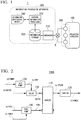
- FIG. 1 is a configuration diagram showing an example of a schematic configuration of an energy management system 1 according to an embodiment of the present invention.
- the energy management system 1 includes a means (collector) for collecting data related to energy efficiency of a production apparatus 100 (plant); a means (holder) for holding the data; and a means (analyzer) for analyzing the data, and realizes a function including at least one of monitoring, simulation, and optimization of energy efficiency during production.
- the energy management system 1 includes a sensor group 200 for measuring elements related to energy efficiency of the production apparatus 100, such as a state of the production apparatus 100 as a management target or an energy flow, an information processing apparatus 300 which processes information related to the production apparatus 100, obtained from the sensor group 200, and a communication network 5 which connects the sensor group 200 to the information processing apparatus 300.
- the production apparatus 100 is, for example, an industrial plant such as a chemical plant, a plant which manages and controls a well site such as a gas field or an oil field, or the periphery thereof, a plant which manages and controls generation of power such as a hydraulic power plant, a thermal power plant, and a nuclear power plant, a plant which manages and controls environmental power generation such as solar generator or a wind turbine, or a plant which manages and controls water and sewerage or controls a dam.
- an industrial plant such as a chemical plant, a plant which manages and controls a well site such as a gas field or an oil field, or the periphery thereof, a plant which manages and controls generation of power such as a hydraulic power plant, a thermal power plant, and a nuclear power plant, a plant which manages and controls environmental power generation such as solar generator or a wind turbine, or a plant which manages and controls water and sewerage or controls a dam.
- the sensor group 200 includes a plurality of field apparatuses such as measurement apparatuses provided in the production apparatus 100 or movable measurement apparatuses.
- the field apparatuses may employ, for example, a sensor apparatus such as a flowmeter or a temperature sensor, a valve apparatus such as a flow control valve or a switch valve, an actuator apparatus such as a fan or a motor, an imaging apparatus such as a camera or a video camera imaging a situation in the plant or a target object, an acoustic apparatus such as a microphone collecting abnormal noise or a speaker generating an alarming sound, a position detection apparatus which outputs position information of each apparatus, and other apparatuses.
- a sensor apparatus such as a flowmeter or a temperature sensor
- a valve apparatus such as a flow control valve or a switch valve
- an actuator apparatus such as a fan or a motor
- an imaging apparatus such as a camera or a video camera imaging a situation in the plant or a target object
- an acoustic apparatus such as
- the communication network 5 is a communication network based on a current signal of 4 to 20 mA, a digital signal superimposed on the current signal, a digital signal in field bus communication or the like, or industrial wireless communication such as ISA100.11 a or Wireless HART (registered trademark).
- the information processing apparatus 300 includes a communicator 310, an information storage 320, a central information processor 330, and an information input/output device 340.
- the communicator 310 acquires information from the sensor group 200 via the communication network 5. For example, the communicator 310 collects information regarding energy efficiency of the production apparatus 100, detected by the sensor group 200, from the sensor group 200.
- the information storage 320 is configured using a recorder such as a random access memory (RAM), an electrically erasable programmable read-only memory (EEPROM), a flash ROM, or a hard disk drive (HDD), or a combination thereof, and stores the information collected by the communicator 310.
- a recorder such as a random access memory (RAM), an electrically erasable programmable read-only memory (EEPROM), a flash ROM, or a hard disk drive (HDD), or a combination thereof, and stores the information collected by the communicator 310.
- the central information processor 330 analyzes and processes the information collected by the communicator 310. For example, the central information processor 330 performs at least one of monitoring, simulation, and optimization of energy efficiency during production performed by the production apparatus 100, on the basis of the information collected by the communicator 310, using a modeling unit in which information regarding energy efficiency of a specific constituent element of the production apparatus 100 is modeled on the basis of a predefined rule. For example, the central information processor 330 uses a modeling unit in which information regarding a structure, a function, and performance related to the energy efficiency of the specific constituent element of the production apparatus 100 is modeled on the basis of the predefined rule.
- the information input/output device 340 includes an input device which receives information which is input from a user, and an output device which provides necessary information to the user.
- the output device may be a display portion which displays display information.
- the information input/output device 340 is formed of a touch panel in which the input device is integrally formed with the display.
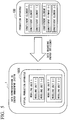
- FIG. 2 is a configuration diagram showing a schematic configuration of an example of the production apparatus 100.
- thermal power generation apparatus 100A will be described as an example of the production apparatus 100 which is a management target of the energy management system 1.
- the thermal power generation apparatus 100A generates power by rotating a turbine 120 with steam generated by a boiler 110, and the boiler 110 converts water (b) which is supplied via a valve 130 into steam (e) using heat obtained by combusting a fuel (a) which is supplied via a fuel pump 140.
- the fuel pump 140 is operated by power (d).
- the valve 130 is operated by air pressure (air (c)) supplied from an air pump 150 which is operated by the power (d).
- the valve 130, the fuel pump 140, the air pump 150 may be included in the boiler 110 as a part thereof.
- a configuration of the boiler 110 including the valve 130, the fuel pump 140, and the air pump 150 is set as a boiler 110A
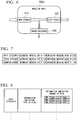
- a configuration of the thermal power generation apparatus 100A may be simply represented as a configuration of including the turbine 120 and the boiler 110A as shown in FIG. 3 .
- a fuel (a), power (d), and water (b) are input to the boiler 110A, and steam (e) is output from the boiler 110A.
- the steam (e) is input to the turbine 120, and power (f) is output from the turbine 120.
- the thermal power generation apparatus 100A is considered as a single configuration, the fuel (a), the power (d), and the water (b) are input to the thermal power generation apparatus 100A, and the power (f) is output from the thermal power generation apparatus 100A.
- the steam (e) is regarded as transmission and reception of energy inside the thermal power generation apparatus 100A, and is not observed from the outside.
- FIG. 4 is a flowchart showing a flow of processes in the energy management system 1 according to the present embodiment.
- the communicator 310 of the information processing apparatus 300 collects data (information) regarding energy efficiency of the production apparatus 100 detected by the sensor group 200, from the sensor group 200 via the communication network 5 (step S10: data collection).
- the information regarding energy efficiency of the production apparatus 100 is, for example, information regarding a fuel, power, and water which are input to the thermal power generation apparatus 100A, information regarding power output from the thermal power generation apparatus 100A, and information regarding steam causing energy consumption inside the thermal power generation apparatus 100A.
- the information regarding a fuel which is input to the thermal power generation apparatus 100A includes a heat quantity per unit fuel amount and an amount of supplied fuels.
- the information regarding power which is input to the thermal power generation apparatus 100A includes an amount of power used in the fuel pump 140 or a control device.
- the information regarding water which is input to the thermal power generation apparatus 100A includes the temperature of water and an amount of supplied water.
- the sensor group 200 collects various information pieces as the information which is input to the thermal power generation apparatus 100A.
- the information regarding power output from the thermal power generation apparatus 100A includes an amount (W) of generated power.
- the information regarding steam causing energy consumption inside the thermal power generation apparatus 100A includes the temperature and pressure of steam, and the flow rate of steam supplied to the turbine 120.
- the information storage 320 stores the data (information) regarding energy efficiency of the production apparatus 100 acquired by the communicator 310 (step S20: data holding).
- the central information processor 330 reads the data (information) regarding energy efficiency of the production apparatus 100 collected by the communicator 310 from the information storage 320, and performs at least one of monitoring, simulation, and optimization of energy efficiency in production activity performed by the production apparatus 100 on the basis of the read data (step S30: data analysis).
- the central information processor 330 uses a modeling unit in which information regarding a structure, a function, and performance related to energy efficiency of a constituent element of the production apparatus 100 is modeled on the basis of a predefined rule.
- FIG. 5 is a schematic diagram showing an image in a case where the constituent elements of the production apparatus 100 are represented by modeling units. Most of such production apparatuses 100 are formed of various kinds of constituent elements having complex structures and delivered from a plurality of manufacturers.
- the energy management system 1 models the constituent elements hierarchically, and represents data regarding energy efficiency hierarchically for each modeling unit obtained through modeling.
- the production apparatus 100 includes a constituent element 1 and a constituent element 2, the constituent element 1 further includes a constituent element 1-1 and a constituent element 1-2, and the constituent element 2 further includes a constituent element 2-1 and a constituent element 2-2.
- the production apparatus 100 is represented as a virtual production apparatus (virtual production apparatus 100X) using a modeling unit in which data regarding energy efficiency of each constituent element of the production apparatus is modeled on the basis of a predefined rule.
- the virtual production apparatus 100X includes a modeling unit 1 and a modeling unit 2, the modeling unit 1 further includes a modeling unit 1-1 and a modeling unit 1-2, and the modeling unit 2 further includes a modeling unit 2-1 and a modeling unit 2-2.
- the energy management system 1 data regarding energy efficiency of each constituent element of the production apparatus 100 is represented hierarchically using the modeling unit. Consequently, the energy management system 1 can perform at least one of monitoring, simulation, and optimization of energy efficiency so as to cope with a complex and diverse production apparatuses 100.
- Constituent elements to be modeled may be some of the constituent elements forming the production apparatus 100, and may be all of the constituent elements. For example, among the constituent elements forming the production apparatus 100, a specific constituent element may be modeled.
- FIG. 6 is a diagram showing a first example of a configuration of a modeling unit.
- a modeling unit 500a shown in FIG. 6 is a basic configuration example of a modeling unit according to the present embodiment.
- the modeling unit 500a includes an input device 510 in which a portion which is input to the production apparatus 100 is modeled, an output device 520 in which a portion output from the production apparatus 100 is modeled, and a consumption portion 530 in which a portion consumed between input to and output from the production apparatus 100 is modeled.
- the portion consumed between input to and output from the production apparatus 100 includes a portion output from the production apparatus 100 due to consumption from input to the production apparatus 100 and output therefrom.
- this consumption attribute may be an attribute related to a portion which is not used effectively and is consumed between input to and output from the modeling unit 500a.
- the structure of the flow of the constituent elements of the production apparatus 100 is represented as the structure of the flow from the input device 510 to the output device 520 or the consumption portion 530.
- the modeling unit 500a includes an input attribute related to input to the modeling unit 500a so as to correspond to the input device 510.
- the modeling unit 500a includes an output attribute related to output from the modeling unit 500a so as to correspond to the output device 520.
- the modeling unit 500a includes a consumption attribute related to consumption between input to and output from the modeling unit 500a so as to correspond to the consumption portion 530.
- the input attribute, the output attribute, and the consumption attribute are attributes indicating features or states of the modeling unit 500a, and are defined on the basis of a function or performance of the constituent element of the production apparatus 100.
- the constituent elements of the production apparatus 100 may be represented as the modeling unit 500a in which the constituent elements are modeled using the structure of the flow from the input device 510 to the output device 520 or the consumption portion 530, and the input attribute, the output attribute, and the consumption attribute.
- the attributes included in the modeling unit 500a includes information in which information indicating the type of flow is associated with information indicating the amount of flow for each type of flow of a target which is input to the modeling unit 500a.
- FIG. 7 is a diagram showing an example of information included in the attributes of the modeling unit 500a. As shown in FIG. 7 , each of the input attribute, the output attribute, and the consumption attribute includes information in which information indicating the type of flow is associated with information indicating the amount of flow.
- the attributes of the modeling unit 500a may include information indicating the amount of flow per unit time as the information indicating the amount of flow.
- FIG 8 is a diagram showing an example of the information indicating the amount of flow included in the attributes of the modeling unit 500a.
- the information indicating an amount of flow associates information ("time period-1", “time period-2”, “time period-3”, ...) indicating a time period with information (“flow rate-1”, “flow rate-2”, “flow rate-3”, 7) indicating the amount of flow for each time period, and maintains the flow rate for each time period (unit time).
- the energy management system 1 can handle a temporal change of a flow rate, and can thus model a constituent element of the production apparatus 100 by taking into consideration the temporal change of the flow rate.
- the information regarding a structure and a function related to energy efficiency of a constituent element of the production apparatus 100 used during modeling includes, for example, information indicating a structure in which water is supplied to the boiler 110 via the valve 130 and a fuel is supplied thereto via the fuel pump 140, or information indicating a structure in which the turbine 120 is driven by steam supplied from the boiler 110.
- the information regarding performance related to energy efficiency of a constituent element of the production apparatus 100 includes, for example, information indicating a relationship between the flow rate of a fuel supplied from the fuel pump 140 and the power required to supply the flow rate, and information indicating the relationship between the amount of steam supplied to the turbine 120 and the amount of power generated thereby.
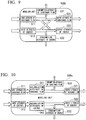
- FIG. 9 is a diagram showing a second example of a configuration of a modeling unit.
- a modeling unit 500b shown in FIG. 9 shows an example in which a substance flow and an energy flow of the production apparatus 100 are modeled using the configuration of the modeling unit 500a shown in FIG. 6 .
- the modeling unit 500b includes an input device 511, an output device 521, and a consumption portion 531 regarding the substance flow, and an input device 512, an output device 522, and a consumption portion 532 regarding the energy flow.
- the modeling unit 500b includes, as an attribute group related to the substance flow, an input attribute of the substance flow, an output attribute of the substance flow, and a consumption attribute of the substance flow, respectively corresponding to the input device 511, the output device 521, and the consumption portion 531 regarding the substance flow.
- the modeling unit 500b includes, as an attribute group related to the energy flow, an input attribute of the energy, an output attribute of the energy, and a consumption attribute of the energy, respectively corresponding to the input device 512, the output device 522, and the consumption portion 532 regarding the energy flow.
- the modeling unit 500b may include not only a flow from the input device 511 regarding the substance flow to the output device 521 or the consumption portion 531 and a flow from the input device 512 regarding the energy to the output device 522 or the consumption portion 532, but also a flow from the input device 511 regarding the substance flow to the output device 522 or the consumption portion 532 regarding the energy, or a flow from the input device 512 regarding related to the energy to the output device 521 or the consumption portion 531 regarding the substance flow.
- the attributes of the modeling unit 500b include information in which the information indicating the type of flow described with reference to FIG. 7 or 8 is associated with information indicating an amount of flow for each set of a substance and energy as targets which are input to the modeling unit 500b.
- each of the input attribute of the substance flow, the output attribute of the substance flow, and the consumption attribute of the substance flow includes information in which information indicating the type of substance flow is associated with information indicating the amount of the substance flow.
- Each of the input attribute of the energy, the output attribute of the energy, and the consumption attribute of the energy includes information in which information indicating the type of energy flow is associated with information indicating the amount of the energy flow.
- the attributes related to the energy flow of the modeling unit 500b include information indicating electrical energy, thermal energy, potential energy, or kinetic energy as the information indicating the type of energy flow.
- FIG. 10 is a diagram showing a third example of a configuration of a modeling unit.
- a modeling unit 500c shown in FIG. 10 is different from the modeling unit 500b shown in FIG. 9 in that an accumulated portion in which a difference (in other words, a portion accumulated in the production apparatus 100) between input to the production apparatus 100 and output from the production apparatus 100 is modeled is further provided.
- the modeling unit 500c includes an input device 511, an output device 521, a consumption portion 531, and an accumulated portion 541 regarding a substance flow, and an input device 512, an output device 522, a consumption portion 532, and an accumulated portion 542 regarding an energy flow.
- the modeling unit 500c includes, as an attribute group related to the substance flow, an input attribute of the substance flow, an output attribute of the substance flow, a consumption attribute of the substance flow, and an accumulation attribute of the substance flow corresponding to the accumulated portion 541 regarding the substance flow.
- the accumulation attribute of the substance flow includes information indicating an accumulation amount of substances representing a difference between an inflow amount of substances which are input to the modeling unit 500c and an outflow amount of substances which are output from the modeling unit 500c.
- the inflow amount of substances is an amount of substances which are input to the input device 511 regarding the substance flow.
- the outflow amount of substances is an amount of substances which are output from the output device 521 and the consumption portion 531 regarding the substance flow.
- the modeling unit 500c includes, as an attribute group related to the energy flow, an input attribute of the energy, an output attribute of the energy, a consumption attribute of the energy, and an accumulation attribute of the energy corresponding to the accumulated portion 542 regarding the energy flow.
- the accumulation attribute of the energy includes information indicating an accumulation amount of energy representing a difference between an inflow amount of energy which is input to the modeling unit 500c and an outflow amount of energy which is output from the modeling unit 500c.
- the inflow amount of energy is an amount of energy which is input to the input device 512 regarding the energy flow.
- the outflow amount of energy is an amount of energy which is output from the output device 522 and the consumption portion 532 regarding the energy flow.
- the substance flow and the energy flow of the production apparatus 100 can also be modeled by taking into consideration accumulation of a substance and accumulation of energy in the production apparatus 100.
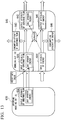
- FIG. 11 is a diagram showing a fourth example of a configuration of a modeling unit.
- FIG. 11 shows an example in which the production apparatus 100 is modeled using a plurality of combined modeling units.
- FIG. 11 shows an example of a modeling unit group in which a modeling unit (1) 550, a modeling unit (2) 560, a modeling unit (3) 570, a modeling unit (4) 580, and a modeling unit (5) 590 are combined with each other.
- Each modeling unit includes at least an input device and an output device.
- FIG. 11 shows input devices and output devices which are connected between the respective modeling units, and does not show other input devices, output devices, and consumption components.
- An output device 551 of the modeling unit (1) 550 is connected to an input device 571 of the modeling unit (3) 570 and an input device 581 of the modeling unit (4) 580.
- the output device 551 is correlated with an output attribute related to a substance flow of the modeling unit (1) 550, and the input device 571 and the input device 581 are respectively correlated with input attributes related to substance flows of the modeling units.
- the output attribute of the output device 551, the input attribute of the input device 571, and the input attribute of the input device 581 include information indicating the same type of substance flow (here, "type-A").
- An output device 552 of the modeling unit (1) 550 is connected to an input device 573 of the modeling unit (3) 570 and an input device 583 of the modeling unit (4) 580.
- the output device 552 is correlated with an output attribute relating to an energy flow of the modeling unit (1) 550, and the input device 573 and the input device 583 are respectively correlated with input attributes related to energy flows of the modeling units.
- the output attribute of the output device 552, the input attribute of the input device 573, and the input attribute of the input device 583 include information indicating the same type of energy flow (here, "type-a").
- An output device 561 of the modeling unit (2) 560 is connected to an input device 572 of the modeling unit (3) 570.
- the output device 561 is correlated with an output attribute related to a substance flow of the modeling unit (2) 560
- the input device 572 is correlated with an input attribute related to a substance flow of the modeling unit (3) 570.
- the output attribute of the output device 561 and the input attribute of the input device 572 include information indicating the same type of substance flow (here, "type-B").
- An output device 562 of the modeling unit (2) 560 and an output device 578 of the modeling unit (3) 570 are connected to an input device 574 of the modeling unit (3) 570.
- the output device 562 is correlated with an output attribute related to an energy flow of the modeling unit (2) 560.
- the output device 578 of the modeling unit (3) 570 is correlated with an output attribute related to an energy flow of the modeling unit (3) 570, and the input device 574 is correlated with an input attribute related to an energy flow of the modeling unit (3) 570.
- the output attribute of the output device 562, the output attribute of the output device 578, and the input attribute of the input device 574 include information indicating the same type of energy flow (here, "type-b").
- An output device 575 of the modeling unit (3) 570 is connected to an input device 582 of the modeling unit (4) 580.
- the output device 575 is correlated with an output attribute related to a substance flow of the modeling unit (3) 570
- the input device 582 is correlated with an input attribute related to a substance flow of the modeling unit (4) 580.
- the output attribute of the output device 575 and the input attribute of the input device 582 include information indicating the same type of substance flow (here, "type-C").
- An output device 576 of the modeling unit (3) 570 is connected to an input device 591 of the modeling unit (5) 590.
- the output device 576 is correlated with an output attribute related to a substance flow of the modeling unit (3) 570
- the input device 591 is correlated with an input attribute related to a substance flow of the modeling unit (5) 590.
- the output attribute of the output device 576 and the input attribute of the input device 591 include information indicating the same type of substance flow (here, "type-D").
- An output device 577 of the modeling unit (3) 570 is connected to an input device 584 of the modeling unit (4) 580 and an input device 592 of the modeling unit (5) 590.
- the output device 577 is correlated with an output attribute related to an energy flow of the modeling unit (3) 570, and the input device 584 and the input device 592 are respectively correlated with input attributes related to energy flows of the modeling units.
- the output attribute of the output device 577, the input attribute of the input device 584, and the input attribute of the input device 592 include information indicating the same type of energy flow (here, "type-c").
- a plurality of modeling units are combined with each other by connecting an output device of a certain modeling unit (first modeling unit) to an input device of another modeling unit (second modeling unit) having an input attribute including the same type of flow as that of an output attribute of the output device. Consequently, the substance flow and the energy flow of the production apparatus 100 can be represented as models using the plurality of combined modeling units.
- the central information processor 330 can perform at least one of monitoring, simulation, and optimization of energy efficiency in production activity performed by the production apparatus 100, on the basis of the collected information regarding energy efficiency using the plurality of combined modeling units.
- FIG. 12 is a diagram showing a fifth example of a configuration of a modeling unit.
- FIG. 12 shows an example in which the production apparatus 100 is modeled using hierarchical modeling units.
- FIG. 12 shows an example in which a modeling unit (6) 610 and a modeling unit (7) 620 which are combined with each other are collectively represented as a higher-rank modeling unit (8) 600.
- the modeling unit (6) 610 and the modeling unit (7) 620 correspond to, for example, the modeling unit 500b shown in FIG. 9 .
- An input device 611, an output device 612, and a consumption component 613 regarding a substance flow of the modeling unit (6) 610, and an input device 621, an output device 622, and a consumption component 623 regarding a substance flow of the modeling unit (7) 620 respectively correspond to the input device 511, the output device 521, and the consumption portion 531 regarding a substance flow of the modeling unit 500b shown in FIG. 9 .
- An input device 614, an output device 615, and a consumption component 616 regarding an energy flow of the modeling unit (6) 610, and an input device 624, an output device 625, and a consumption component 626 regarding a substance flow of the modeling unit (7) 620 respectively correspond to the input device 512, the output device 522, and the consumption portion 532 regarding an energy flow of the modeling unit 500b shown in FIG. 9 .
- the modeling unit (6) 610 and the modeling unit (7) 620 are, for example, combined modeling units in which the output device and the input device having a flow of the same type are connected to each other in the same manner as in the fourth example described with reference to FIG. 11 .
- the output device 612 of the modeling unit (6) 610 is connected to the input device 621 of the modeling unit (7) 620.
- the consumption component 616 of the modeling unit (6) 610 is connected to the input device 624 of the modeling unit (7) 620.
- An input device, an output device, and a consumption component which are not connected between the plurality of combined modeling units in the higher-rank modeling unit (8) 600 are connected to an input device, an output device, or a consumption component of the higher-rank modeling unit (8) 600.
- Respectively corresponding input attribute, output attribute, and consumption attribute of the input device, the output device, and the consumption component of the higher-rank modeling unit (8) 600 are used as an input attribute, an output attribute, and a consumption attribute corresponding to an input device, an output device, and a consumption component which are respectively connected thereto.
- the input device 611 and the consumption component 613 regarding the substance flow and the input device 614 and the output device 615 regarding the energy flow of the modeling unit (6) 610 are connected to the modeling unit (7) 620, and are connected to any one of the input device, the output device, and the consumption component of the higher-rank modeling unit (8) 600.
- the output device 622 and the consumption component 623 regarding the substance flow and the output device 625 and the consumption component 626 regarding the energy flow of the modeling unit (7) 620 are not connected to the modeling unit (6) 610, and are connected to any one of the input device, the output device, and the consumption component of the higher-rank modeling unit (8) 600.
- the input device 611 regarding the substance flow of the modeling unit (6) 610 is connected to an input device 601 of the higher-rank modeling unit (8) 600.
- An input attribute corresponding to the input device 601 of the higher-rank modeling unit (8) 600 is an input attribute related to the substance flow corresponding to the input device 611 of the modeling unit (6) 610.
- the input device 614 regarding the energy flow of the modeling unit (6) 610 is connected to an input device 604 of the higher-rank modeling unit (8) 600.
- An input attribute corresponding to the input device 604 of the higher-rank modeling unit (8) 600 is an input attribute related to the substance flow corresponding to the input device 614 of the modeling unit (6) 610.
- the output device 622 regarding the substance flow of the modeling unit (7) 620 is connected to an output device 602 of the higher-rank modeling unit (8) 600.
- An output attribute corresponding to the output device 602 of the higher-rank modeling unit (8) 600 is an output attribute related to the substance flow corresponding to the output device 622 of the modeling unit (7) 620.
- the consumption component 626 regarding the energy flow of the modeling unit (7) 620 is connected to a consumption component 606 of the higher-rank modeling unit (8) 600.
- a consumption attribute corresponding to the consumption component 606 of the higher-rank modeling unit (8) 600 is a consumption attribute related to the energy flow corresponding to the consumption component 626 of the modeling unit (7) 620.
- attributes respectively corresponding to the plurality of input devices, the plurality of output devices, or the plurality of consumption components are collected and are used as attributes of the higher-rank modeling unit (8) 600.
- the consumption component 613 regarding the substance flow of the modeling unit (6) 610 and the consumption component 623 regarding the substance flow of the modeling unit (7) 620 are connected to the consumption component 603 of the higher-rank modeling unit (8) 600.
- a consumption attribute corresponding to the consumption component 603 of the higher-rank modeling unit (8) 600 is obtained by collecting a consumption attribute related to a substance flow corresponding to the consumption component 613 and a consumption attribute related to a substance flow corresponding to the consumption component 623.
- the output device 615 regarding the energy flow of the modeling unit (6) 610 and the output device 625 regarding the energy flow of the modeling unit (7) 620 are connected to the output device 605 of the higher-rank modeling unit (8) 600.
- An output attribute corresponding to the output device 605 of the higher-rank modeling unit (8) 600 is obtained by collecting an output attribute related to an energy flow corresponding to the output device 615 and an output attribute related to a substance flow corresponding to the output device 625.
- the substance flow and the energy flow of the production apparatus 100 can be represented as models using the hierarchical modeling units. Therefore, the production apparatus 100 which is formed of various kinds of constituent elements having considerably complex structures can be modeled hierarchically.
- the central information processor 330 can perform at least one of monitoring, simulation, and optimization of energy efficiency in production activity performed by the production apparatus 100, on the basis of the collected information regarding energy efficiency using a plurality of hierarchical combined modeling units.
- an attribute related to a substance flow of the modeling unit may include information regarding unit apparent energy indicating energy per unit amount corresponding to the type of the substance.
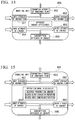
- FIG. 13 is a diagram showing a sixth example of a configuration of a modeling unit.
- FIG. 13 shows an example of including a plurality of combined modeling units in the same manner as in the above-described fourth example or fifth example.
- a modeling unit (9) 630 and a modeling unit (10) 640 are combined with each other, and the modeling unit (9) 630 is a modeling unit on an upstream side of the modeling unit (10) 640.
- the modeling unit (9) 630 corresponds to the modeling unit (6) 610 shown in FIG. 12 , but only the output device 632 regarding a substance flow is shown, and the remaining input device, output devices, and consumption components are not shown.
- the modeling unit (10) 640 corresponds to the modeling unit (7) 620 shown in FIG. 12 , and includes an input device 641, an output device 642, and a consumption component 643 related to a substance flow, and an input device 644, an output device 645, and a consumption component 646 regarding an energy flow.
- the output device 632 of the modeling unit (9) 630 is connected to the input device 641 of the modeling unit (10) 640.
- unit apparent energy included in an input attribute related to a substance flow corresponding to the input device 641 of the modeling unit (10) 640 is used as a value of unit apparent energy included in an output attribute related to a substance flow corresponding to the output device 632 of the modeling unit (9) 630 connected on the upstream side.
- the unit apparent energy included in an input attribute related to a substance flow corresponding to the input device 641 of the modeling unit (10) 640 may be a predefined value of unit apparent energy.
- the central information processor 330 calculates a value of unit apparent energy included in an output attribute related to a substance flow corresponding to the output device 642 of the modeling unit (10) 640 on the basis of the input attribute related to a substance flow corresponding to the input device 641 of the modeling unit (10) 640, an input attribute related to an energy flow corresponding to the input device 644, and an output attribute related to an energy flow corresponding to the output device 645.
- the central information processor 330 calculates a value of unit apparent energy included in the output attribute related to a substance flow corresponding to the output device 642 of the modeling unit (10) 640 using the following Equation 1.
- e MOUT E IN ⁇ E OUT + e MIN ⁇ f MIN / f MOUT where:
- the central information processor 330 may use a value obtained by distributing a total of unit apparent energy in the modeling unit (10) 640 in proportion to an outflow amount of substance flow in each of the plurality of output attributes, as a value of unit apparent energy included in each of the plurality of output attributes.
- the total of unit apparent energy in the modeling unit (10) 640 is a value of unit apparent energy included in an output attribute related to of the entire modeling unit (10) 640, calculated according to the above Equation 1.
- FIG. 14 is a diagram showing a seventh example of a configuration of a modeling unit.
- a modeling unit 650 shown in FIG. 14 corresponds to, for example, the modeling unit 500b shown in FIG. 9 .
- the modeling unit 650 includes an input device 651, an output device 652, and a consumption component 653 regarding a substance flow, and an input device 654, an output device 655, and a consumption component 656 regarding an energy flow.
- the modeling unit 650 includes apparent energy efficiency calculated from another attribute thereof as an attribute.
- the central information processor 330 calculates the apparent energy efficiency using the following Equation 2.
- Equation 2 E OUT + e MOUT ⁇ f MOUT / E IN + e MIN ⁇ f MIN
- FIG. 15 is a diagram showing an eighth example of a configuration of a modeling unit.
- a modeling unit 660 shown in FIG. 15 corresponds to, for example, the modeling unit 500b shown in FIG. 9 .
- the modeling unit 660 includes an input device 661, an output device 662, and a consumption component 663 regarding a substance flow, and an input device 664, an output device 665, and a consumption component 666 regarding an energy flow.
- the modeling unit 660 includes an attribute (operation mode attribute) including at least one of pieces of information regarding a desired production amount indicating a desired value of an outflow amount of a target which is output from the modeling unit 660, a desired output combination proportion indicating a desired proportion of an outflow amount for each type of target which is output from the modeling unit 660, and a desired input combination proportion indicating a desired proportion for each type of target which is input to the modeling unit 660.
- an attribute including at least one of pieces of information regarding a desired production amount indicating a desired value of an outflow amount of a target which is output from the modeling unit 660, a desired output combination proportion indicating a desired proportion of an outflow amount for each type of target which is output from the modeling unit 660, and a desired input combination proportion indicating a desired proportion for each type of target which is input to the modeling unit 660.
- the plant and an automation system are designed to achieve the maximum energy efficiency prior to construction of the plant. Simulation using a virtual plant model is performed for optimization design of energy efficiency. Most of such plants are formed of various kinds of elements having complex structures and delivered from a plurality of manufacturers.
- the energy management system 1 can model hierarchically various kinds of constituent elements having complex structures, and can thus represent energy related data for each portion hierarchically.
- the energy management system 1 models the production apparatus 100 using a modeling unit (for example, refer to the first example or the second example of the modeling unit shown in FIG. 6 or 9 ), and also models the production apparatus 100 using a plurality of combined modeling units (for example, refer to the fourth example of a modeling unit shown in FIG. 11 ), or a modeling unit in which a plurality of combined modeling units are hierarchically modeled as a higher-rank modeling unit (for example, refer to the fifth example of a modeling unit shown in FIG. 12 ).
- a modeling unit for example, refer to the first example or the second example of the modeling unit shown in FIG. 6 or 9
- a plurality of combined modeling units for example, refer to the fourth example of a modeling unit shown in FIG. 11
- a modeling unit in which a plurality of combined modeling units are hierarchically modeled as a higher-rank modeling unit for example, refer
- the modeling unit includes an input attribute, an output attribute, and a consumption attribute (for example, refer to the first example of a modeling unit shown in FIG. 6 ).
- the modeling unit includes an attribute group related to a substance flow and an attribute group relating to an energy flow (for example, refer to the second example of a modeling unit shown in FIG. 9 ).
- Each attribute includes information indicating the type of flow and information indicating an amount of flow (for example, refer to FIGS. 7 and 8 ), and is formed for each type of flow (for example, refer to the fourth example of a modeling unit shown in FIG. 11 ). Consequently, energy related data can be represented in a unified manner even for different kinds of constituent elements from a plurality of manufacturers.
- the amount of fuel or the amount of input power required to obtain expected output power can be computed on the basis of performance characteristics of a constituent element (for example, the boiler 110 or the turbine 120) of the apparatus.
- Energy efficiency for each output power amount can be calculated (by using, for example, Equation 2) on the basis of a relationship between each of a plurality of output power amounts and the necessary amount of fuel or the amount of input power respectively corresponding thereto, and thus an operation condition causing the maximum energy efficiency can be determined.
- Selection or design of a constituent element of the thermal power generation apparatus 100A is replaced, and simulation based on the same computation is performed, so that a configuration or design of the thermal power generation apparatus 100A appropriate for an expected output power amount can be determined.
- the energy management system 1 performs modeling by hierarchically combining modeling units having general structures such as an input attribute, an output attribute, and a consumption attribute, and thus includes a high degree of freedom when hierarchically modeling various constituent elements of the production apparatus 100. Therefore, the energy management system 1 can perform flexible simulation so as to cope with a complex and diverse production apparatuses 100 (plants) using the modeling method with a high degree of freedom.
- the energy management system 1 of the present embodiment represents characteristics of options of respective constituent elements based on modeling units in a unified manner using an input attribute, an output attribute, and a consumption attribute, and information indicating the type of flow and information indicating the amount of flow included in each attribute (for example, refer to FIGS. 6, 7, 8 , 9 and 11 ), and can thus easily compare the characteristics with each other or perform simulation using the information.
- a specific machine type of a specific constituent element (for example, the fuel pump 140) of the thermal power generation apparatus 100A shown in FIG. 2 is selected, if performance of the entire thermal power generation apparatus is computed for each condition using performance (for example, a characteristic of a necessary power amount corresponding to a fuel supply amount) of each of machine types of candidate fuel pumps, and is compared for each machine type of the candidate fuel pumps, it is possible to select a machine type capable of realizing optimal performance.
- performance for example, a characteristic of a necessary power amount corresponding to a fuel supply amount
- a raw material or a material is converted into a product by direct energy such as power or heat, or, conversely, thermal energy or electrical energy is generated through combustion of a raw material or a chemical reaction of a raw material.
- direct energy such as power or heat
- thermal energy or electrical energy is generated through combustion of a raw material or a chemical reaction of a raw material.
- Energy efficiency of the production system may be generally represented by a ratio between a value obtained through a production process and energy used to generate the value. However, a generated value differs for each production process, and thus it may not be easy to perform comparison using an index of energy efficiency common to a plurality of different production processes.
- the energy management system 1 can convert a raw material into energy using unit apparent energy delivered from an output attribute of a modeling unit in an upstream step to an input attribute of a modeling unit in a downstream step with respect to an attribute related to a substance flow (raw material), and can evaluate energy efficiency with an energy ratio (for example, refer to the sixth example of a modeling unit shown in FIG. 13 ). Consequently, it is possible to apply a common index of energy efficiency to a plurality of different modeling units and thus to compare energy efficiency between modeling units or compare effects of improvement measures with each other.
- time delay occurs from input of a raw material to the process to the appearance of energy as output.
- delay due to the time delay is required to be represented as an accumulation element.
- an operation schedule between a plurality of step is adjusted, or the plurality of step is synchronized with each other.
- it is necessary to represent a function of a tank or a store accumulating substances such as a raw material or a function of a battery or a heat storage accumulating energy as an accumulation element in order to model the function.
- the energy management system 1 can model or the production apparatus 100 in which the above-described delay due to the time delay occurs or which includes an accumulation function so as to represent accumulation elements of a substance and energy as attributes of a modeling unit (for example, refer to the third example of a modeling unit shown in FIG. 10 ), and can thus perform advanced simulation of optimization of energy efficiency using the modeled production apparatus.
- the energy management system 1 can model reuse of the energy and the raw material using a plurality of modeling units which are combined with each other by connecting an consumption component of a certain modeling unit to an input device of another modeling unit (for example, refer to the fourth example of a modeling unit shown in FIG. 11 ).
- the energy management system 1 can model and treat the reuse without treating the reused raw material or energy as a consumption attribute in a higher-rank modeling unit according to the example in which a plurality of combined modeling units are collected and are treated as the higher-rank modeling unit (for example, refer to the fifth example of a modeling unit shown in FIG. 12 ).
- the energy management system 1 gives an operation mode attribute to a modeling unit (for example, refer to the eighth example of a modeling unit shown in FIG. 15 ), and can thus perform simulation of optimization of energy efficiency through control of the operation mode.
- the energy management system 1 may be a computer based energy management system realizing a function including at least one of monitoring, simulation, and optimization of energy efficiency in production activity.
- a program for realizing the above-described functions may be recorded on a computer readable recorder, and the above-described functions may be realized by a computer system reading the program recorded on the recorder and executing the program.
- the "computer system” mentioned here is a computer system built into the information processing apparatus 300, and is assumed to include an OS or hardware such as peripheral devices.
- the "computer system” is assumed to include a home page providing environment (or display environment) as long as a WWW system is used.
- the "computer readable recorder” indicates a portable medium such as a flexible disc, a magneto-optical disc, a ROM, or a CD-ROM, and a storage such as a hard disk built into the computer system.
- the "computer readable recorder” may include a medium which holds dynamically for a short period of time, such as a communication line in a case where the program is transmitted via a network such as the Internet or a communication line such as a telephone channel, and a medium which holds the program for a predetermined period of time, such as a nonvolatile memory inside the computer system which serves as a server or a client in that case.
- the program may realize some of the above-described functions, and may realize the above-described functions in combination with a program which includes already been recorded in the computer system.
- a part or the whole of the information processing apparatus 300 in the above-described embodiment may be realized as an integrated circuit such as a large scale integration (LSI) circuit.
- the respective functional blocks of the information processing apparatus 300 may be separately generated as a processor, and some or all of the functional blocks may be integrated into a processor.
- a technique for an integrated circuit is not limited to LSI, and may be realized by a dedicated circuit or a general purpose processor.
- an integrated circuit based on the technique may be used.
Landscapes
- Engineering & Computer Science (AREA)
- Physics & Mathematics (AREA)
- General Physics & Mathematics (AREA)
- Automation & Control Theory (AREA)
- General Engineering & Computer Science (AREA)
- Theoretical Computer Science (AREA)
- Quality & Reliability (AREA)
- Manufacturing & Machinery (AREA)
- Computer Hardware Design (AREA)
- Evolutionary Computation (AREA)
- Geometry (AREA)
- Computer Networks & Wireless Communication (AREA)
- Power Engineering (AREA)
- Management, Administration, Business Operations System, And Electronic Commerce (AREA)
- Testing And Monitoring For Control Systems (AREA)
Abstract
Description
- The present invention relates to an energy management system, an energy management method, and a program.
- Priority is claimed on
Japanese Patent Application No. 2014-083677, filed April 15, 2014 - As one of the means which includes a great effect of improving energy efficiency during operation of a plant (production apparatus), the plant and an automation system are designed to achieve the maximum energy efficiency prior to construction of the plant. Simulation using a virtual plant model is performed to optimize the design for energy efficiency.
- As a technique related to an energy related system,
Patent Document 1 discloses an energy management system including a data holder for collecting and preserving "energy consumption data" in "data related to energy efficiency".Patent Document 2 discloses an energy monitoring system having a function of collecting data from a power monitor and grouping the data.Patent Document 3 discloses a plant information management apparatus which manages a data group related to a plant in correlation with a "unit". -
- [Patent Document 1]
Japanese Unexamined Patent Application, First Publication No. 2010-271826 - [Patent Document 2]
Japanese Patent No. 4747756 - [Patent Document 3]
Japanese Patent No. 5029632 - Since most of such plants are formed of various kinds of elements having complex structures and delivered from a plurality of manufacturers, it may not be easy to perform flexible simulation of complex and diverse plants.
- For example, in the technique disclosed in
Patent Document 1, "energy input information", "energy output information", and the like are not mentioned except for the "energy consumption data", and thus it is not easy to cope with complex and diverse plants. In the technique disclosed inPatent Document 2, data collected from the power monitor is grouped, and thus adding or changing of a power monitor is facilitated, but it is not easy to cope with complex and diverse plants if data is only collected from the power monitor. In the technique disclosed inPatent Document 3, a data group related to a plant is managed in correlation with a "unit", but this "unit" is restricted to being used to present data, and thus it is not easy to perform monitoring, simulation, or optimization of energy efficiency to cope with complex and diverse plants. - An aspect of the present invention is to provide an energy management system, an energy management method, and a program capable of performing at least one of monitoring, simulation, or optimization of energy efficiency so as to cope with complex and diverse plants (production apparatuses).
-
- (1) An energy management system of one aspect of the invention may include a collector that collects information regarding energy efficiency of a production apparatus and a processing section that performs at least one of monitoring, simulation, and optimization of energy efficiency in production activity performed by the production apparatus, on the basis of the information regarding energy efficiency collected by the collector, using a modeling unit in which information regarding energy efficiency of a constituent element of the production apparatus is modeled on the basis of a predefined rule.
- (2) Above stated energy management system may further include the processor performs at least one of monitoring, simulation, and optimization of energy efficiency in production activity performed by the production apparatus, on the basis of the information regarding energy efficiency collected by the collector, using the modeling unit obtained through hierarchical modeling.
- (3) In the above stated energy management system, the modeling unit is obtained by modeling information regarding one selected from the group consisting of a structure, a function, and performance related to energy efficiency of a specific constituent element of the production apparatus on the basis of a predefined rule.
- (4) In the above stated energy management system, the modeling unit includes, as attributes indicating a feature or a state of the modeling unit, one selected from the group consisting of an input attribute relating to input to the modeling unit, an output attribute related to output from the modeling unit, and a consumption attribute related to consumption between input to and output from the modeling unit.
- (5) In the above stated energy management system, the modeling unit includes, as the attributes indicating the feature and the state of the modeling unit, one selected from the group consisting of an attribute group including an input attribute, an output attribute, and a consumption attribute related to a substance flow, and one selected from the group consisting of an attribute group including an input attribute, an output attribute, and a consumption attribute related to an energy flow.
- (6) In the above stated energy management system, the modeling unit further includes, as the attributes indicating the feature and the state of the modeling unit, an accumulation attribute including information indicating an accumulation amount representing a difference between an inflow amount to the modeling unit and an outflow amount from the modeling unit.
- (7) In the above stated energy management system, the modeling unit includes, as the attributes indicating the feature and the state of the modeling unit, an accumulation attribute related to a substance flow, including information indicating an accumulation amount of substance related to a difference between an inflow amount of substance which is input to the modeling unit and an outflow amount of substance which is output from the modeling unit, and an accumulation attribute related to an energy flow, including information indicating an accumulation amount of energy representing a difference between an inflow amount of energy which is input to the modeling unit and an outflow amount of energy which is output from the modeling unit.
- (8) In the above stated energy management system, the attributes of the modeling unit include information in which information indicating the type of flow is associated with information indicating an amount of the flow for each type of flow of a target which is input to the modeling unit.
- (9) In the above stated energy management system, in a case where a target which is input to the modeling unit is energy, the attribute related to an energy flow of the modeling unit includes information indicating one or more of the group consisting of electrical energy, thermal energy, potential energy, and kinetic energy, as the information indicating the type of flow.
- (10) In the above stated energy management system, the attributes of the modeling unit includes information indicating an amount of the flow per unit time as the information indicating an amount of the flow.
- (11) In the above stated energy management system, the modeling unit includes: an input device obtained by modeling a portion which is input to the production apparatus; an output device obtained by modeling a portion which is output from the production apparatus; and a consumption component obtained by modeling a portion consumed between input to and output from the production apparatus.
- (12) In the above stated energy management system, the attributes of the modeling unit include information in which information indicating the type of flow is associated with information indicating an amount of the flow for each type of flow of a target which is input to the modeling unit.
The processor performs at least one of monitoring, simulation, and optimization of energy efficiency in production activity performed by the production apparatus, on the basis of the information regarding energy efficiency collected by the collector, using a plurality of the modeling units which are combined with each other by connecting the output device of a first modeling unit to the input device of a second modeling unit having the input attribute including the same type of the flow as a type of the flow of the output attribute of the output device. - (13) In the above stated energy management system, the plurality of combined modeling units are collected into a single modeling unit as a higher-rank modeling unit.
One selected from the group consisting of the input device, the output device, and the consumption component which is not connected between the plurality of combined modeling units in the higher-rank modeling unit is connected to one selected from the group consisting of the input device, the output device, and the consumption component of the higher-rank modeling unit.
The input attribute, the output attribute, and the consumption attribute respectively corresponding to the input device, the output device, the consumption component of the higher-rank modeling unit are used as the input attribute, the output attribute, and the consumption attribute respectively corresponding to the input device, the output device, the consumption component connected thereto. - (14) In the above stated energy management system, in a case where there are one or more of the group consisting of a plurality of input devices, a plurality of output devices, and a plurality of consumption components which are not connected between the plurality of combined modeling units in the higher-rank modeling unit, attributes respectively corresponding to one or more selected from the group consisting of the plurality of input devices, the plurality of output devices, and the plurality of consumption components, are collected and are used as attributes of the higher-rank modeling unit.
- (15) In the above stated energy management system, in a case where a target which is input to the modeling unit is a substance, the attributes related to a substance flow of the modeling unit include information regarding unit apparent energy indicating an energy per unit amount corresponding to a type of the substance.
- The processor sets the unit apparent energy included in an input attribute related to a substance flow of the modeling unit to a value of the unit apparent energy included in an output attribute related to a substance flow of a modeling unit which is combined on an upstream side or to a predefined value of the unit apparent energy, and calculates a value of the unit apparent energy included in an output attribute related to a substance flow of the modeling unit on the basis of the input attribute related to a substance flow of the modeling unit, an input attribute related to an energy flow, and an output attribute related to an energy flow.
- According to the aspects of the present invention, it is possible to perform at least one of monitoring, simulation, or optimization of energy efficiency to cope with complex and diverse plants (production apparatuses).
-
-
FIG. 1 is a configuration diagram showing an example of a schematic configuration of an energy management system according to an embodiment of the present invention. -
FIG. 2 is a configuration diagram showing a schematic configuration of an example of a production apparatus of the present invention. -
FIG. 3 is a configuration diagram showing another configuration example of the production apparatus of the present invention. -
FIG. 4 is a flowchart showing a flow of processes in the energy management system according to the embodiment of the present invention. -
FIG. 5 is a schematic diagram showing an image in a case where constituent elements of the production apparatus of the present invention are represented by modeling units. -
FIG. 6 is a diagram showing a first example of a configuration of a modeling unit of the present invention. -
FIG. 7 is a diagram showing an example of information included in an attribute of the modeling unit of the present invention. -
FIG. 8 is a diagram showing an example of information indicating an amount of flow included in the attribute of the modeling unit of the present invention. -
FIG 9 is a diagram showing a second example of a configuration of a modeling unit of the present invention. -
FIG. 10 is a diagram showing a third example of a configuration of a modeling unit of the present invention. -
FIG. 11 is a diagram showing a fourth example of a configuration of a modeling unit of the present invention. -
FIG. 12 is a diagram showing a fifth example of a configuration of a modeling unit of the present invention. -
FIG. 13 is a diagram showing a sixth example of a configuration of a modeling unit of the present invention. -
FIG. 14 is a diagram showing a seventh example of a configuration of a modeling unit of the present invention. -
FIG. 15 is a diagram showing an eighth example of a configuration of a modeling unit of the present invention. - Hereinafter, with reference to the drawings, embodiments of the present invention will be described.
-
FIG. 1 is a configuration diagram showing an example of a schematic configuration of anenergy management system 1 according to an embodiment of the present invention. Theenergy management system 1 includes a means (collector) for collecting data related to energy efficiency of a production apparatus 100 (plant); a means (holder) for holding the data; and a means (analyzer) for analyzing the data, and realizes a function including at least one of monitoring, simulation, and optimization of energy efficiency during production. - In the example shown in
FIG. 1 , theenergy management system 1 includes asensor group 200 for measuring elements related to energy efficiency of theproduction apparatus 100, such as a state of theproduction apparatus 100 as a management target or an energy flow, aninformation processing apparatus 300 which processes information related to theproduction apparatus 100, obtained from thesensor group 200, and acommunication network 5 which connects thesensor group 200 to theinformation processing apparatus 300. - The
production apparatus 100 is, for example, an industrial plant such as a chemical plant, a plant which manages and controls a well site such as a gas field or an oil field, or the periphery thereof, a plant which manages and controls generation of power such as a hydraulic power plant, a thermal power plant, and a nuclear power plant, a plant which manages and controls environmental power generation such as solar generator or a wind turbine, or a plant which manages and controls water and sewerage or controls a dam. - The
sensor group 200 includes a plurality of field apparatuses such as measurement apparatuses provided in theproduction apparatus 100 or movable measurement apparatuses. The field apparatuses may employ, for example, a sensor apparatus such as a flowmeter or a temperature sensor, a valve apparatus such as a flow control valve or a switch valve, an actuator apparatus such as a fan or a motor, an imaging apparatus such as a camera or a video camera imaging a situation in the plant or a target object, an acoustic apparatus such as a microphone collecting abnormal noise or a speaker generating an alarming sound, a position detection apparatus which outputs position information of each apparatus, and other apparatuses. - The
communication network 5 is a communication network based on a current signal of 4 to 20 mA, a digital signal superimposed on the current signal, a digital signal in field bus communication or the like, or industrial wireless communication such as ISA100.11 a or Wireless HART (registered trademark). - The
information processing apparatus 300 includes acommunicator 310, aninformation storage 320, acentral information processor 330, and an information input/output device 340. - The communicator 310 (collector) acquires information from the
sensor group 200 via thecommunication network 5. For example, thecommunicator 310 collects information regarding energy efficiency of theproduction apparatus 100, detected by thesensor group 200, from thesensor group 200. - The
information storage 320 is configured using a recorder such as a random access memory (RAM), an electrically erasable programmable read-only memory (EEPROM), a flash ROM, or a hard disk drive (HDD), or a combination thereof, and stores the information collected by thecommunicator 310. - The central information processor 330 (processor) analyzes and processes the information collected by the
communicator 310. For example, thecentral information processor 330 performs at least one of monitoring, simulation, and optimization of energy efficiency during production performed by theproduction apparatus 100, on the basis of the information collected by thecommunicator 310, using a modeling unit in which information regarding energy efficiency of a specific constituent element of theproduction apparatus 100 is modeled on the basis of a predefined rule. For example, thecentral information processor 330 uses a modeling unit in which information regarding a structure, a function, and performance related to the energy efficiency of the specific constituent element of theproduction apparatus 100 is modeled on the basis of the predefined rule. - This modeling unit will be described later in detail.
- The information input/
output device 340 includes an input device which receives information which is input from a user, and an output device which provides necessary information to the user. The output device may be a display portion which displays display information. For example, the information input/output device 340 is formed of a touch panel in which the input device is integrally formed with the display. -
FIG. 2 is a configuration diagram showing a schematic configuration of an example of theproduction apparatus 100. - Herein, with reference to
FIG. 2 , a thermalpower generation apparatus 100A will be described as an example of theproduction apparatus 100 which is a management target of theenergy management system 1. - The thermal
power generation apparatus 100A generates power by rotating aturbine 120 with steam generated by aboiler 110, and theboiler 110 converts water (b) which is supplied via avalve 130 into steam (e) using heat obtained by combusting a fuel (a) which is supplied via afuel pump 140. Thefuel pump 140 is operated by power (d). Thevalve 130 is operated by air pressure (air (c)) supplied from anair pump 150 which is operated by the power (d). - The
valve 130, thefuel pump 140, theair pump 150 may be included in theboiler 110 as a part thereof. In this case, if a configuration of theboiler 110 including thevalve 130, thefuel pump 140, and theair pump 150 is set as aboiler 110A, a configuration of the thermalpower generation apparatus 100A may be simply represented as a configuration of including theturbine 120 and theboiler 110A as shown inFIG. 3 . In this case, a fuel (a), power (d), and water (b) are input to theboiler 110A, and steam (e) is output from theboiler 110A. The steam (e) is input to theturbine 120, and power (f) is output from theturbine 120. If the thermalpower generation apparatus 100A is considered as a single configuration, the fuel (a), the power (d), and the water (b) are input to the thermalpower generation apparatus 100A, and the power (f) is output from the thermalpower generation apparatus 100A. The steam (e) is regarded as transmission and reception of energy inside the thermalpower generation apparatus 100A, and is not observed from the outside. -
FIG. 4 is a flowchart showing a flow of processes in theenergy management system 1 according to the present embodiment. - First, the
communicator 310 of theinformation processing apparatus 300 collects data (information) regarding energy efficiency of theproduction apparatus 100 detected by thesensor group 200, from thesensor group 200 via the communication network 5 (step S10: data collection). - When the thermal
power generation apparatus 100A shown inFIG. 3 is exemplified, the information regarding energy efficiency of theproduction apparatus 100 is, for example, information regarding a fuel, power, and water which are input to the thermalpower generation apparatus 100A, information regarding power output from the thermalpower generation apparatus 100A, and information regarding steam causing energy consumption inside the thermalpower generation apparatus 100A. The information regarding a fuel which is input to the thermalpower generation apparatus 100A includes a heat quantity per unit fuel amount and an amount of supplied fuels. The information regarding power which is input to the thermalpower generation apparatus 100A includes an amount of power used in thefuel pump 140 or a control device. The information regarding water which is input to the thermalpower generation apparatus 100A includes the temperature of water and an amount of supplied water. It is necessary to appropriately control the ratio between the amount of supplied fuels and the amount of water in theenergy management system 1. There is a case where the necessary amount of supplied fuels changes depending on the heat quantity of the fuel, or there is a case where the necessary heating amount changes depending on the temperature of water. Thus, thesensor group 200 collects various information pieces as the information which is input to the thermalpower generation apparatus 100A. The information regarding power output from the thermalpower generation apparatus 100A includes an amount (W) of generated power. The information regarding steam causing energy consumption inside the thermalpower generation apparatus 100A includes the temperature and pressure of steam, and the flow rate of steam supplied to theturbine 120. - Next, the
information storage 320 stores the data (information) regarding energy efficiency of theproduction apparatus 100 acquired by the communicator 310 (step S20: data holding). Thecentral information processor 330 reads the data (information) regarding energy efficiency of theproduction apparatus 100 collected by thecommunicator 310 from theinformation storage 320, and performs at least one of monitoring, simulation, and optimization of energy efficiency in production activity performed by theproduction apparatus 100 on the basis of the read data (step S30: data analysis). Thecentral information processor 330 uses a modeling unit in which information regarding a structure, a function, and performance related to energy efficiency of a constituent element of theproduction apparatus 100 is modeled on the basis of a predefined rule. - Next, a description will be made of a modeling unit in which data (information) regarding energy efficiency of a constituent element forming the
production apparatus 100 is modeled on the basis of a predefined rule. -
FIG. 5 is a schematic diagram showing an image in a case where the constituent elements of theproduction apparatus 100 are represented by modeling units. Most ofsuch production apparatuses 100 are formed of various kinds of constituent elements having complex structures and delivered from a plurality of manufacturers. Theenergy management system 1 models the constituent elements hierarchically, and represents data regarding energy efficiency hierarchically for each modeling unit obtained through modeling. - For example, as shown in
FIG. 5 , it is assumed that theproduction apparatus 100 includes aconstituent element 1 and aconstituent element 2, theconstituent element 1 further includes a constituent element 1-1 and a constituent element 1-2, and theconstituent element 2 further includes a constituent element 2-1 and a constituent element 2-2. In theenergy management system 1 according to the present embodiment, theproduction apparatus 100 is represented as a virtual production apparatus (virtual production apparatus 100X) using a modeling unit in which data regarding energy efficiency of each constituent element of the production apparatus is modeled on the basis of a predefined rule. Herein, thevirtual production apparatus 100X includes amodeling unit 1 and amodeling unit 2, themodeling unit 1 further includes a modeling unit 1-1 and a modeling unit 1-2, and themodeling unit 2 further includes a modeling unit 2-1 and a modeling unit 2-2. As mentioned above, in theenergy management system 1, data regarding energy efficiency of each constituent element of theproduction apparatus 100 is represented hierarchically using the modeling unit. Consequently, theenergy management system 1 can perform at least one of monitoring, simulation, and optimization of energy efficiency so as to cope with a complex anddiverse production apparatuses 100. - Constituent elements to be modeled may be some of the constituent elements forming the
production apparatus 100, and may be all of the constituent elements. For example, among the constituent elements forming theproduction apparatus 100, a specific constituent element may be modeled. - Next, a configuration example of a modeling unit will be described.
-
FIG. 6 is a diagram showing a first example of a configuration of a modeling unit. - A
modeling unit 500a shown inFIG. 6 is a basic configuration example of a modeling unit according to the present embodiment. Themodeling unit 500a includes aninput device 510 in which a portion which is input to theproduction apparatus 100 is modeled, anoutput device 520 in which a portion output from theproduction apparatus 100 is modeled, and aconsumption portion 530 in which a portion consumed between input to and output from theproduction apparatus 100 is modeled. The portion consumed between input to and output from theproduction apparatus 100 includes a portion output from theproduction apparatus 100 due to consumption from input to theproduction apparatus 100 and output therefrom. For example, this consumption attribute may be an attribute related to a portion which is not used effectively and is consumed between input to and output from themodeling unit 500a. - In other words, in the
modeling unit 500a, the structure of the flow of the constituent elements of theproduction apparatus 100 is represented as the structure of the flow from theinput device 510 to theoutput device 520 or theconsumption portion 530. - The
modeling unit 500a includes an input attribute related to input to themodeling unit 500a so as to correspond to theinput device 510. Themodeling unit 500a includes an output attribute related to output from themodeling unit 500a so as to correspond to theoutput device 520. Themodeling unit 500a includes a consumption attribute related to consumption between input to and output from themodeling unit 500a so as to correspond to theconsumption portion 530. The input attribute, the output attribute, and the consumption attribute are attributes indicating features or states of themodeling unit 500a, and are defined on the basis of a function or performance of the constituent element of theproduction apparatus 100. - As mentioned above, the constituent elements of the
production apparatus 100 may be represented as themodeling unit 500a in which the constituent elements are modeled using the structure of the flow from theinput device 510 to theoutput device 520 or theconsumption portion 530, and the input attribute, the output attribute, and the consumption attribute. - The attributes included in the
modeling unit 500a includes information in which information indicating the type of flow is associated with information indicating the amount of flow for each type of flow of a target which is input to themodeling unit 500a. -
FIG. 7 is a diagram showing an example of information included in the attributes of themodeling unit 500a. As shown inFIG. 7 , each of the input attribute, the output attribute, and the consumption attribute includes information in which information indicating the type of flow is associated with information indicating the amount of flow. - The attributes of the
modeling unit 500a may include information indicating the amount of flow per unit time as the information indicating the amount of flow. -
FIG 8 is a diagram showing an example of the information indicating the amount of flow included in the attributes of themodeling unit 500a. As shown inFIG. 8 , the information indicating an amount of flow associates information ("time period-1", "time period-2", "time period-3", ...) indicating a time period with information ("flow rate-1", "flow rate-2", "flow rate-3", ...) indicating the amount of flow for each time period, and maintains the flow rate for each time period (unit time). - Consequently, the
energy management system 1 can handle a temporal change of a flow rate, and can thus model a constituent element of theproduction apparatus 100 by taking into consideration the temporal change of the flow rate. - In addition, the information regarding a structure and a function related to energy efficiency of a constituent element of the
production apparatus 100 used during modeling includes, for example, information indicating a structure in which water is supplied to theboiler 110 via thevalve 130 and a fuel is supplied thereto via thefuel pump 140, or information indicating a structure in which theturbine 120 is driven by steam supplied from theboiler 110. The information regarding performance related to energy efficiency of a constituent element of theproduction apparatus 100 includes, for example, information indicating a relationship between the flow rate of a fuel supplied from thefuel pump 140 and the power required to supply the flow rate, and information indicating the relationship between the amount of steam supplied to theturbine 120 and the amount of power generated thereby. -
FIG. 9 is a diagram showing a second example of a configuration of a modeling unit. - A
modeling unit 500b shown inFIG. 9 shows an example in which a substance flow and an energy flow of theproduction apparatus 100 are modeled using the configuration of themodeling unit 500a shown inFIG. 6 . Themodeling unit 500b includes aninput device 511, anoutput device 521, and aconsumption portion 531 regarding the substance flow, and aninput device 512, anoutput device 522, and aconsumption portion 532 regarding the energy flow. - The
modeling unit 500b includes, as an attribute group related to the substance flow, an input attribute of the substance flow, an output attribute of the substance flow, and a consumption attribute of the substance flow, respectively corresponding to theinput device 511, theoutput device 521, and theconsumption portion 531 regarding the substance flow. Themodeling unit 500b includes, as an attribute group related to the energy flow, an input attribute of the energy, an output attribute of the energy, and a consumption attribute of the energy, respectively corresponding to theinput device 512, theoutput device 522, and theconsumption portion 532 regarding the energy flow. - As mentioned above, the substance flow and the energy flow of the
production apparatus 100 can be represented as models. Themodeling unit 500b may include not only a flow from theinput device 511 regarding the substance flow to theoutput device 521 or theconsumption portion 531 and a flow from theinput device 512 regarding the energy to theoutput device 522 or theconsumption portion 532, but also a flow from theinput device 511 regarding the substance flow to theoutput device 522 or theconsumption portion 532 regarding the energy, or a flow from theinput device 512 regarding related to the energy to theoutput device 521 or theconsumption portion 531 regarding the substance flow. - The attributes of the
modeling unit 500b include information in which the information indicating the type of flow described with reference toFIG. 7 or 8 is associated with information indicating an amount of flow for each set of a substance and energy as targets which are input to themodeling unit 500b. For example, each of the input attribute of the substance flow, the output attribute of the substance flow, and the consumption attribute of the substance flow includes information in which information indicating the type of substance flow is associated with information indicating the amount of the substance flow. Each of the input attribute of the energy, the output attribute of the energy, and the consumption attribute of the energy includes information in which information indicating the type of energy flow is associated with information indicating the amount of the energy flow. - For example, as the type of energy flow, there is electrical energy, thermal energy, potential energy, or kinetic energy. For example, in a case where a target which is input to the
modeling unit 500b is energy, the attributes related to the energy flow of themodeling unit 500b include information indicating electrical energy, thermal energy, potential energy, or kinetic energy as the information indicating the type of energy flow. -
FIG. 10 is a diagram showing a third example of a configuration of a modeling unit. - A
modeling unit 500c shown inFIG. 10 is different from themodeling unit 500b shown inFIG. 9 in that an accumulated portion in which a difference (in other words, a portion accumulated in the production apparatus 100) between input to theproduction apparatus 100 and output from theproduction apparatus 100 is modeled is further provided. For example, themodeling unit 500c includes aninput device 511, anoutput device 521, aconsumption portion 531, and an accumulated portion 541 regarding a substance flow, and aninput device 512, anoutput device 522, aconsumption portion 532, and an accumulatedportion 542 regarding an energy flow. - The
modeling unit 500c includes, as an attribute group related to the substance flow, an input attribute of the substance flow, an output attribute of the substance flow, a consumption attribute of the substance flow, and an accumulation attribute of the substance flow corresponding to the accumulated portion 541 regarding the substance flow. - For example, the accumulation attribute of the substance flow includes information indicating an accumulation amount of substances representing a difference between an inflow amount of substances which are input to the
modeling unit 500c and an outflow amount of substances which are output from themodeling unit 500c. The inflow amount of substances is an amount of substances which are input to theinput device 511 regarding the substance flow. The outflow amount of substances is an amount of substances which are output from theoutput device 521 and theconsumption portion 531 regarding the substance flow. - The
modeling unit 500c includes, as an attribute group related to the energy flow, an input attribute of the energy, an output attribute of the energy, a consumption attribute of the energy, and an accumulation attribute of the energy corresponding to the accumulatedportion 542 regarding the energy flow. - The accumulation attribute of the energy includes information indicating an accumulation amount of energy representing a difference between an inflow amount of energy which is input to the
modeling unit 500c and an outflow amount of energy which is output from themodeling unit 500c. The inflow amount of energy is an amount of energy which is input to theinput device 512 regarding the energy flow. The outflow amount of energy is an amount of energy which is output from theoutput device 522 and theconsumption portion 532 regarding the energy flow. - As mentioned above, the substance flow and the energy flow of the
production apparatus 100 can also be modeled by taking into consideration accumulation of a substance and accumulation of energy in theproduction apparatus 100. -
FIG. 11 is a diagram showing a fourth example of a configuration of a modeling unit. -
FIG. 11 shows an example in which theproduction apparatus 100 is modeled using a plurality of combined modeling units. Here,FIG. 11 shows an example of a modeling unit group in which a modeling unit (1) 550, a modeling unit (2) 560, a modeling unit (3) 570, a modeling unit (4) 580, and a modeling unit (5) 590 are combined with each other. Each modeling unit includes at least an input device and an output device.FIG. 11 shows input devices and output devices which are connected between the respective modeling units, and does not show other input devices, output devices, and consumption components. - An
output device 551 of the modeling unit (1) 550 is connected to aninput device 571 of the modeling unit (3) 570 and aninput device 581 of the modeling unit (4) 580. Theoutput device 551 is correlated with an output attribute related to a substance flow of the modeling unit (1) 550, and theinput device 571 and theinput device 581 are respectively correlated with input attributes related to substance flows of the modeling units. The output attribute of theoutput device 551, the input attribute of theinput device 571, and the input attribute of theinput device 581 include information indicating the same type of substance flow (here, "type-A"). - An
output device 552 of the modeling unit (1) 550 is connected to aninput device 573 of the modeling unit (3) 570 and aninput device 583 of the modeling unit (4) 580. Theoutput device 552 is correlated with an output attribute relating to an energy flow of the modeling unit (1) 550, and theinput device 573 and theinput device 583 are respectively correlated with input attributes related to energy flows of the modeling units. The output attribute of theoutput device 552, the input attribute of theinput device 573, and the input attribute of theinput device 583 include information indicating the same type of energy flow (here, "type-a"). - An
output device 561 of the modeling unit (2) 560 is connected to aninput device 572 of the modeling unit (3) 570. Theoutput device 561 is correlated with an output attribute related to a substance flow of the modeling unit (2) 560, and theinput device 572 is correlated with an input attribute related to a substance flow of the modeling unit (3) 570. The output attribute of theoutput device 561 and the input attribute of theinput device 572 include information indicating the same type of substance flow (here, "type-B"). - An
output device 562 of the modeling unit (2) 560 and anoutput device 578 of the modeling unit (3) 570 are connected to aninput device 574 of the modeling unit (3) 570. Theoutput device 562 is correlated with an output attribute related to an energy flow of the modeling unit (2) 560. Theoutput device 578 of the modeling unit (3) 570 is correlated with an output attribute related to an energy flow of the modeling unit (3) 570, and theinput device 574 is correlated with an input attribute related to an energy flow of the modeling unit (3) 570. The output attribute of theoutput device 562, the output attribute of theoutput device 578, and the input attribute of theinput device 574 include information indicating the same type of energy flow (here, "type-b"). - An
output device 575 of the modeling unit (3) 570 is connected to aninput device 582 of the modeling unit (4) 580. Theoutput device 575 is correlated with an output attribute related to a substance flow of the modeling unit (3) 570, and theinput device 582 is correlated with an input attribute related to a substance flow of the modeling unit (4) 580. The output attribute of theoutput device 575 and the input attribute of theinput device 582 include information indicating the same type of substance flow (here, "type-C"). - An
output device 576 of the modeling unit (3) 570 is connected to aninput device 591 of the modeling unit (5) 590. Theoutput device 576 is correlated with an output attribute related to a substance flow of the modeling unit (3) 570, and theinput device 591 is correlated with an input attribute related to a substance flow of the modeling unit (5) 590. The output attribute of theoutput device 576 and the input attribute of theinput device 591 include information indicating the same type of substance flow (here, "type-D"). - An
output device 577 of the modeling unit (3) 570 is connected to aninput device 584 of the modeling unit (4) 580 and aninput device 592 of the modeling unit (5) 590. Theoutput device 577 is correlated with an output attribute related to an energy flow of the modeling unit (3) 570, and theinput device 584 and theinput device 592 are respectively correlated with input attributes related to energy flows of the modeling units. The output attribute of theoutput device 577, the input attribute of theinput device 584, and the input attribute of theinput device 592 include information indicating the same type of energy flow (here, "type-c"). - As mentioned above, in the fourth example of an modeling unit, a plurality of modeling units are combined with each other by connecting an output device of a certain modeling unit (first modeling unit) to an input device of another modeling unit (second modeling unit) having an input attribute including the same type of flow as that of an output attribute of the output device. Consequently, the substance flow and the energy flow of the
production apparatus 100 can be represented as models using the plurality of combined modeling units. - The
central information processor 330 can perform at least one of monitoring, simulation, and optimization of energy efficiency in production activity performed by theproduction apparatus 100, on the basis of the collected information regarding energy efficiency using the plurality of combined modeling units. -
FIG. 12 is a diagram showing a fifth example of a configuration of a modeling unit. -
FIG. 12 shows an example in which theproduction apparatus 100 is modeled using hierarchical modeling units. Here,FIG. 12 shows an example in which a modeling unit (6) 610 and a modeling unit (7) 620 which are combined with each other are collectively represented as a higher-rank modeling unit (8) 600. - The modeling unit (6) 610 and the modeling unit (7) 620 correspond to, for example, the
modeling unit 500b shown inFIG. 9 . Aninput device 611, anoutput device 612, and aconsumption component 613 regarding a substance flow of the modeling unit (6) 610, and aninput device 621, anoutput device 622, and aconsumption component 623 regarding a substance flow of the modeling unit (7) 620 respectively correspond to theinput device 511, theoutput device 521, and theconsumption portion 531 regarding a substance flow of themodeling unit 500b shown inFIG. 9 . Aninput device 614, anoutput device 615, and aconsumption component 616 regarding an energy flow of the modeling unit (6) 610, and aninput device 624, anoutput device 625, and aconsumption component 626 regarding a substance flow of the modeling unit (7) 620 respectively correspond to theinput device 512, theoutput device 522, and theconsumption portion 532 regarding an energy flow of themodeling unit 500b shown inFIG. 9 . - The modeling unit (6) 610 and the modeling unit (7) 620 are, for example, combined modeling units in which the output device and the input device having a flow of the same type are connected to each other in the same manner as in the fourth example described with reference to
FIG. 11 . - Here, with respect to a substance flow, the
output device 612 of the modeling unit (6) 610 is connected to theinput device 621 of the modeling unit (7) 620. With respect to an energy flow, theconsumption component 616 of the modeling unit (6) 610 is connected to theinput device 624 of the modeling unit (7) 620. - An input device, an output device, and a consumption component which are not connected between the plurality of combined modeling units in the higher-rank modeling unit (8) 600 are connected to an input device, an output device, or a consumption component of the higher-rank modeling unit (8) 600. Respectively corresponding input attribute, output attribute, and consumption attribute of the input device, the output device, and the consumption component of the higher-rank modeling unit (8) 600 are used as an input attribute, an output attribute, and a consumption attribute corresponding to an input device, an output device, and a consumption component which are respectively connected thereto.
- In the example shown in
FIG. 12 , theinput device 611 and theconsumption component 613 regarding the substance flow and theinput device 614 and theoutput device 615 regarding the energy flow of the modeling unit (6) 610 are connected to the modeling unit (7) 620, and are connected to any one of the input device, the output device, and the consumption component of the higher-rank modeling unit (8) 600. Theoutput device 622 and theconsumption component 623 regarding the substance flow and theoutput device 625 and theconsumption component 626 regarding the energy flow of the modeling unit (7) 620 are not connected to the modeling unit (6) 610, and are connected to any one of the input device, the output device, and the consumption component of the higher-rank modeling unit (8) 600. - Specifically, the
input device 611 regarding the substance flow of the modeling unit (6) 610 is connected to aninput device 601 of the higher-rank modeling unit (8) 600. An input attribute corresponding to theinput device 601 of the higher-rank modeling unit (8) 600 is an input attribute related to the substance flow corresponding to theinput device 611 of the modeling unit (6) 610. - The
input device 614 regarding the energy flow of the modeling unit (6) 610 is connected to aninput device 604 of the higher-rank modeling unit (8) 600. An input attribute corresponding to theinput device 604 of the higher-rank modeling unit (8) 600 is an input attribute related to the substance flow corresponding to theinput device 614 of the modeling unit (6) 610. - The
output device 622 regarding the substance flow of the modeling unit (7) 620 is connected to anoutput device 602 of the higher-rank modeling unit (8) 600. An output attribute corresponding to theoutput device 602 of the higher-rank modeling unit (8) 600 is an output attribute related to the substance flow corresponding to theoutput device 622 of the modeling unit (7) 620. - The
consumption component 626 regarding the energy flow of the modeling unit (7) 620 is connected to aconsumption component 606 of the higher-rank modeling unit (8) 600. A consumption attribute corresponding to theconsumption component 606 of the higher-rank modeling unit (8) 600 is a consumption attribute related to the energy flow corresponding to theconsumption component 626 of the modeling unit (7) 620. - In a case where there a plurality of input devices, a plurality of output devices, or a plurality of consumption components which are not connected between the plurality of combined modeling units in the higher-rank modeling unit (8) 600, attributes respectively corresponding to the plurality of input devices, the plurality of output devices, or the plurality of consumption components are collected and are used as attributes of the higher-rank modeling unit (8) 600.
- In the example shown in
FIG. 12 , theconsumption component 613 regarding the substance flow of the modeling unit (6) 610 and theconsumption component 623 regarding the substance flow of the modeling unit (7) 620 are connected to theconsumption component 603 of the higher-rank modeling unit (8) 600. A consumption attribute corresponding to theconsumption component 603 of the higher-rank modeling unit (8) 600 is obtained by collecting a consumption attribute related to a substance flow corresponding to theconsumption component 613 and a consumption attribute related to a substance flow corresponding to theconsumption component 623. - The
output device 615 regarding the energy flow of the modeling unit (6) 610 and theoutput device 625 regarding the energy flow of the modeling unit (7) 620 are connected to theoutput device 605 of the higher-rank modeling unit (8) 600. An output attribute corresponding to theoutput device 605 of the higher-rank modeling unit (8) 600 is obtained by collecting an output attribute related to an energy flow corresponding to theoutput device 615 and an output attribute related to a substance flow corresponding to theoutput device 625. - As mentioned above, in the fifth example of a modeling unit, the substance flow and the energy flow of the
production apparatus 100 can be represented as models using the hierarchical modeling units. Therefore, theproduction apparatus 100 which is formed of various kinds of constituent elements having considerably complex structures can be modeled hierarchically. - The
central information processor 330 can perform at least one of monitoring, simulation, and optimization of energy efficiency in production activity performed by theproduction apparatus 100, on the basis of the collected information regarding energy efficiency using a plurality of hierarchical combined modeling units. - If a target which is input to a modeling unit is a substance, an attribute related to a substance flow of the modeling unit may include information regarding unit apparent energy indicating energy per unit amount corresponding to the type of the substance.
-
FIG. 13 is a diagram showing a sixth example of a configuration of a modeling unit.FIG. 13 shows an example of including a plurality of combined modeling units in the same manner as in the above-described fourth example or fifth example. As shown inFIG. 13 , a modeling unit (9) 630 and a modeling unit (10) 640 are combined with each other, and the modeling unit (9) 630 is a modeling unit on an upstream side of the modeling unit (10) 640. For example, the modeling unit (9) 630 corresponds to the modeling unit (6) 610 shown inFIG. 12 , but only theoutput device 632 regarding a substance flow is shown, and the remaining input device, output devices, and consumption components are not shown. The modeling unit (10) 640 corresponds to the modeling unit (7) 620 shown inFIG. 12 , and includes aninput device 641, anoutput device 642, and aconsumption component 643 related to a substance flow, and aninput device 644, anoutput device 645, and aconsumption component 646 regarding an energy flow. - The
output device 632 of the modeling unit (9) 630 is connected to theinput device 641 of the modeling unit (10) 640. - Here, unit apparent energy included in an input attribute related to a substance flow corresponding to the
input device 641 of the modeling unit (10) 640 is used as a value of unit apparent energy included in an output attribute related to a substance flow corresponding to theoutput device 632 of the modeling unit (9) 630 connected on the upstream side. The unit apparent energy included in an input attribute related to a substance flow corresponding to theinput device 641 of the modeling unit (10) 640 may be a predefined value of unit apparent energy. - The
central information processor 330 calculates a value of unit apparent energy included in an output attribute related to a substance flow corresponding to theoutput device 642 of the modeling unit (10) 640 on the basis of the input attribute related to a substance flow corresponding to theinput device 641 of the modeling unit (10) 640, an input attribute related to an energy flow corresponding to theinput device 644, and an output attribute related to an energy flow corresponding to theoutput device 645. - For example, the
central information processor 330 calculates a value of unit apparent energy included in the output attribute related to a substance flow corresponding to theoutput device 642 of the modeling unit (10) 640 using the followingEquation 1.
- EIN: Input energy;
- EOUT: Output energy;
- eMIN: Input unit apparent energy;
- eMOUT: Output unit apparent energy;
- fMIN: Input substance flow amount; and
- fMOUT: Output substance flow amount.
- In a case where the modeling unit (10) 640 includes output devices corresponding to a plurality of output attributes related to a substance flow, the
central information processor 330 may use a value obtained by distributing a total of unit apparent energy in the modeling unit (10) 640 in proportion to an outflow amount of substance flow in each of the plurality of output attributes, as a value of unit apparent energy included in each of the plurality of output attributes. The total of unit apparent energy in the modeling unit (10) 640 is a value of unit apparent energy included in an output attribute related to of the entire modeling unit (10) 640, calculated according to theabove Equation 1. -
FIG. 14 is a diagram showing a seventh example of a configuration of a modeling unit. - A
modeling unit 650 shown inFIG. 14 corresponds to, for example, themodeling unit 500b shown inFIG. 9 . Themodeling unit 650 includes aninput device 651, anoutput device 652, and aconsumption component 653 regarding a substance flow, and aninput device 654, anoutput device 655, and aconsumption component 656 regarding an energy flow. In the seventh example, regarding an attribute of themodeling unit 650, themodeling unit 650 includes apparent energy efficiency calculated from another attribute thereof as an attribute. - For example, the
central information processor 330 calculates the apparent energy efficiency using the followingEquation 2.
- EE: Apparent energy efficiency;
- EIN: Input energy;
- EOUT: Output energy;
- eMIN: Input unit apparent energy;
- eMOUT: Output unit apparent energy;
- fMIN: Input substance flow amount; and
- fMOUT: Output substance flow amount.
-
FIG. 15 is a diagram showing an eighth example of a configuration of a modeling unit. - A
modeling unit 660 shown inFIG. 15 corresponds to, for example, themodeling unit 500b shown inFIG. 9 . Themodeling unit 660 includes aninput device 661, anoutput device 662, and aconsumption component 663 regarding a substance flow, and an input device 664, anoutput device 665, and aconsumption component 666 regarding an energy flow. In the eighth example, themodeling unit 660 includes an attribute (operation mode attribute) including at least one of pieces of information regarding a desired production amount indicating a desired value of an outflow amount of a target which is output from themodeling unit 660, a desired output combination proportion indicating a desired proportion of an outflow amount for each type of target which is output from themodeling unit 660, and a desired input combination proportion indicating a desired proportion for each type of target which is input to themodeling unit 660. As mentioned above, since themodeling unit 660 includes the operation mode attribute, and thus power consumption can be reduced by controlling an operation mode of a production facility, such as adjustment of a desired production amount or transition to a pause state, it is possible to improve energy efficiency. - Next, examples of use of the
energy management system 1 according to the present embodiment will be described. - As one of the means in which an effect of improving energy efficiency during operation of the production apparatus 100 (plant) is great, the plant and an automation system are designed to achieve the maximum energy efficiency prior to construction of the plant. Simulation using a virtual plant model is performed for optimization design of energy efficiency. Most of such plants are formed of various kinds of elements having complex structures and delivered from a plurality of manufacturers.
- The
energy management system 1 can model hierarchically various kinds of constituent elements having complex structures, and can thus represent energy related data for each portion hierarchically. For example, theenergy management system 1 models theproduction apparatus 100 using a modeling unit (for example, refer to the first example or the second example of the modeling unit shown inFIG. 6 or9 ), and also models theproduction apparatus 100 using a plurality of combined modeling units (for example, refer to the fourth example of a modeling unit shown inFIG. 11 ), or a modeling unit in which a plurality of combined modeling units are hierarchically modeled as a higher-rank modeling unit (for example, refer to the fifth example of a modeling unit shown inFIG. 12 ). - The modeling unit includes an input attribute, an output attribute, and a consumption attribute (for example, refer to the first example of a modeling unit shown in
FIG. 6 ). For example, the modeling unit includes an attribute group related to a substance flow and an attribute group relating to an energy flow (for example, refer to the second example of a modeling unit shown inFIG. 9 ). Each attribute includes information indicating the type of flow and information indicating an amount of flow (for example, refer toFIGS. 7 and 8 ), and is formed for each type of flow (for example, refer to the fourth example of a modeling unit shown inFIG. 11 ). Consequently, energy related data can be represented in a unified manner even for different kinds of constituent elements from a plurality of manufacturers. - For example, in a case of the thermal
power generation apparatus 100A shown inFIG. 2 , assuming that a specific condition (for example, the temperature of water) of the thermalpower generation apparatus 100A is set to a constant value, the amount of fuel or the amount of input power required to obtain expected output power can be computed on the basis of performance characteristics of a constituent element (for example, theboiler 110 or the turbine 120) of the apparatus. Energy efficiency for each output power amount can be calculated (by using, for example, Equation 2) on the basis of a relationship between each of a plurality of output power amounts and the necessary amount of fuel or the amount of input power respectively corresponding thereto, and thus an operation condition causing the maximum energy efficiency can be determined. Selection or design of a constituent element of the thermalpower generation apparatus 100A is replaced, and simulation based on the same computation is performed, so that a configuration or design of the thermalpower generation apparatus 100A appropriate for an expected output power amount can be determined. - As mentioned above, the
energy management system 1 performs modeling by hierarchically combining modeling units having general structures such as an input attribute, an output attribute, and a consumption attribute, and thus includes a high degree of freedom when hierarchically modeling various constituent elements of theproduction apparatus 100. Therefore, theenergy management system 1 can perform flexible simulation so as to cope with a complex and diverse production apparatuses 100 (plants) using the modeling method with a high degree of freedom. - When constituent elements of the production apparatus 100 (plant) are procured, constituent elements which include the same function but different energy consumption characteristics may be selected. In this case, the
energy management system 1 of the present embodiment represents characteristics of options of respective constituent elements based on modeling units in a unified manner using an input attribute, an output attribute, and a consumption attribute, and information indicating the type of flow and information indicating the amount of flow included in each attribute (for example, refer toFIGS. 6, 7, 8 ,9 and11 ), and can thus easily compare the characteristics with each other or perform simulation using the information. - For example, when a specific machine type of a specific constituent element (for example, the fuel pump 140) of the thermal
power generation apparatus 100A shown inFIG. 2 is selected, if performance of the entire thermal power generation apparatus is computed for each condition using performance (for example, a characteristic of a necessary power amount corresponding to a fuel supply amount) of each of machine types of candidate fuel pumps, and is compared for each machine type of the candidate fuel pumps, it is possible to select a machine type capable of realizing optimal performance. - For example, if product information from a plurality of manufacturers is supplied so as to be unified to a representation method of characteristics of a constituent element used in a modeling unit, it is possible to more efficiently perform plant design or procurement maximizing energy efficiency. Such information is provided by electronic means, and thus an information processing technique is more easily used.
- In a production process in the production apparatus 100 (plant), a raw material or a material is converted into a product by direct energy such as power or heat, or, conversely, thermal energy or electrical energy is generated through combustion of a raw material or a chemical reaction of a raw material. Thus, in order to measure and monitor energy efficiency, it is necessary to understand both of a substance flow and an energy flow along with conversion therebetween. The
energy management system 1 according to the present embodiment can understand the balance of energy in a wider range so as to treat a substance flow and an energy flow in a unified manner (for example, refer to the second example of a modeling unit shown inFIG. 9 ). - In a case where optimization of energy efficiency is examined, it is necessary not only to monitor energy efficiency of the entire production system of hierarchical modeling units but also to specify a location to be improved by recognizing low level energy efficiency or check an improvement effect. Energy efficiency of the production system may be generally represented by a ratio between a value obtained through a production process and energy used to generate the value. However, a generated value differs for each production process, and thus it may not be easy to perform comparison using an index of energy efficiency common to a plurality of different production processes.
- The
energy management system 1 according to the present embodiment can convert a raw material into energy using unit apparent energy delivered from an output attribute of a modeling unit in an upstream step to an input attribute of a modeling unit in a downstream step with respect to an attribute related to a substance flow (raw material), and can evaluate energy efficiency with an energy ratio (for example, refer to the sixth example of a modeling unit shown inFIG. 13 ). Consequently, it is possible to apply a common index of energy efficiency to a plurality of different modeling units and thus to compare energy efficiency between modeling units or compare effects of improvement measures with each other. - In a production process of the production apparatus 100 (plant), generally, time delay occurs from input of a raw material to the process to the appearance of energy as output. In order to model an energy flow and a substance flow in such a process, delay due to the time delay is required to be represented as an accumulation element. In order to maximize energy efficiency of each step, there is a case where an operation schedule between a plurality of step is adjusted, or the plurality of step is synchronized with each other. In this case, it is necessary to represent a function of a tank or a store accumulating substances such as a raw material or a function of a battery or a heat storage accumulating energy as an accumulation element in order to model the function.
- The
energy management system 1 according to the present embodiment can model or theproduction apparatus 100 in which the above-described delay due to the time delay occurs or which includes an accumulation function so as to represent accumulation elements of a substance and energy as attributes of a modeling unit (for example, refer to the third example of a modeling unit shown inFIG. 10 ), and can thus perform advanced simulation of optimization of energy efficiency using the modeled production apparatus. - As one of methods of improving energy efficiency, there is a method of reusing energy or a raw material which is wastefully consumed in a production process. It is also important to model and simulate such improvement of energy efficiency.
- The
energy management system 1 according to the present embodiment can model reuse of the energy and the raw material using a plurality of modeling units which are combined with each other by connecting an consumption component of a certain modeling unit to an input device of another modeling unit (for example, refer to the fourth example of a modeling unit shown inFIG. 11 ). Theenergy management system 1 can model and treat the reuse without treating the reused raw material or energy as a consumption attribute in a higher-rank modeling unit according to the example in which a plurality of combined modeling units are collected and are treated as the higher-rank modeling unit (for example, refer to the fifth example of a modeling unit shown inFIG. 12 ). - As another method of improving energy efficiency, there is a method of reducing energy consumption by controlling an operation mode of a production facility, such as adjustment of a desired production amount or transition to a pause state. The
energy management system 1 according to the present embodiment gives an operation mode attribute to a modeling unit (for example, refer to the eighth example of a modeling unit shown inFIG. 15 ), and can thus perform simulation of optimization of energy efficiency through control of the operation mode. - As mentioned above, several embodiments of the present invention have been described in detail with reference to the drawings, but a specific configuration is not limited to the above-described embodiments, and includes design within the scope without departing from the spirit of the invention. For example, the respective functions described in the embodiments may be optionally combined with each other.
- The functions of some or all of the respective sections of the
information processing apparatus 300 in the above-described embodiments may be realized by a computer. For example, theenergy management system 1 according to the above-described embodiment may be a computer based energy management system realizing a function including at least one of monitoring, simulation, and optimization of energy efficiency in production activity. In this case, a program for realizing the above-described functions may be recorded on a computer readable recorder, and the above-described functions may be realized by a computer system reading the program recorded on the recorder and executing the program. The "computer system" mentioned here is a computer system built into theinformation processing apparatus 300, and is assumed to include an OS or hardware such as peripheral devices. - The "computer system" is assumed to include a home page providing environment (or display environment) as long as a WWW system is used.
- The "computer readable recorder" indicates a portable medium such as a flexible disc, a magneto-optical disc, a ROM, or a CD-ROM, and a storage such as a hard disk built into the computer system. The "computer readable recorder" may include a medium which holds dynamically for a short period of time, such as a communication line in a case where the program is transmitted via a network such as the Internet or a communication line such as a telephone channel, and a medium which holds the program for a predetermined period of time, such as a nonvolatile memory inside the computer system which serves as a server or a client in that case. The program may realize some of the above-described functions, and may realize the above-described functions in combination with a program which includes already been recorded in the computer system.
- A part or the whole of the
information processing apparatus 300 in the above-described embodiment may be realized as an integrated circuit such as a large scale integration (LSI) circuit. The respective functional blocks of theinformation processing apparatus 300 may be separately generated as a processor, and some or all of the functional blocks may be integrated into a processor. A technique for an integrated circuit is not limited to LSI, and may be realized by a dedicated circuit or a general purpose processor. In addition, in a case where a technique for an integrated circuit replacing the LSI circuit will appear with the advance of a semiconductor technique, an integrated circuit based on the technique may be used. -
- 1 ENERGY MANAGEMENT SYSTEM
- 5 COMMUNICATION NETWORK
- 100 PRODUCTION APPARATUS
- 100A THERMAL POWER GENERATION APPARATUS
- 110 AND
- 110A BOILER
- 120 TURBINE
- 130 VALVE
- 140 FUEL PUMP
- 150 AIR PUMP
- 200 SENSOR GROUP
- 300 INFORMATION PROCESSING APPARATUS
- 310 COMMUNICATOR
- 320 INFORMATION STORAGE
- 330 CENTRAL INFORMATION PROCESSOR
- 340 INFORMATION INPUT/OUTPUT DEVICE
- 500, 500a, 500b, 500c, 550, 560, 570, 580, 590, 600, 610, 620, 630, 640, 650, AND
- 660 MODELING UNIT
Claims (22)
- An energy management system comprising:a collector configured to collect information regarding energy efficiency of a production apparatus; anda processor configured to perform at least one of monitoring, simulation, and optimization of energy efficiency in production activity performed by the production apparatus, on the basis of the information regarding energy efficiency collected by the collector, using a modeling unit in which information regarding energy efficiency of a constituent element of the production apparatus is modeled on the basis of a predefined rule.
- The energy management system according to claim 1,
wherein the processor performs at least one of monitoring, simulation, and optimization of energy efficiency in production activity performed by the production apparatus, on the basis of the information regarding energy efficiency collected by the collector, using the modeling unit obtained through hierarchical modeling. - The energy management system according to claim 1 or 2,
wherein the modeling unit is obtained by modeling information regarding at least one selected from the group consisting of a structure, a function, and performance related to energy efficiency of a specific constituent element of the production apparatus on the basis of a predefined rule. - The energy management system according to any one of claims 1 to 3,
wherein the modeling unit comprises, as attributes indicating a feature or a state of the modeling unit, at least one selected from the group consisting of an input attribute relating to input to the modeling unit, an output attribute related to output from the modeling unit, and a consumption attribute related to consumption between input to and output from the modeling unit. - The energy management system according to claim 4,
wherein the modeling unit comprises, as the attributes indicating the feature and the state of the modeling unit, at least one selected from the group consisting of an attribute group including an input attribute, an output attribute, and a consumption attribute related to a substance flow, and at least one selected from the group consisting of an attribute group including an input attribute, an output attribute, and a consumption attribute related to an energy flow. - The energy management system according to claim 4 or 5,
wherein the modeling unit further comprises, as the attributes indicating the feature and the state of the modeling unit, an accumulation attribute including information indicating an accumulation amount representing a difference between an inflow amount to the modeling unit and an outflow amount from the modeling unit. - The energy management system according to claim 5 or 6,
wherein the modeling unit comprises, as the attributes indicating the feature and the state of the modeling unit, an accumulation attribute related to a substance flow, including information indicating an accumulation amount of substance related to a difference between an inflow amount of substance which is input to the modeling unit and an outflow amount of substance which is output from the modeling unit, and an accumulation attribute related to an energy flow, including information indicating an accumulation amount of energy representing a difference between an inflow amount of energy which is input to the modeling unit and an outflow amount of energy which is output from the modeling unit. - The energy management system according to any one of claims 4 to 7,
wherein the attributes of the modeling unit include information in which information indicating the type of flow is associated with information indicating an amount of the flow for each type of flow of a target which is input to the modeling unit. - The energy management system according to claim 8,
wherein, in a case where a target which is input to the modeling unit is energy, the attribute related to an energy flow of the modeling unit includes information indicating one or more of the group consisting of electrical energy, thermal energy, potential energy, and kinetic energy, as the information indicating the type of flow. - The energy management system according to claim 8 or 9,
wherein the attributes of the modeling unit includes information indicating an amount of the flow per unit time as the information indicating an amount of the flow. - The energy management system according to any one of claims 4 to 10,
wherein the modeling unit comprises:an input device obtained by modeling a portion which is input to the production apparatus;an output device obtained by modeling a portion which is output from the production apparatus; anda consumption component obtained by modeling a component consumed between input to and output from the production apparatus. - The energy management system according to claim 11,
wherein the attributes of the modeling unit include information in which information indicating the type of flow is associated with information indicating an amount of the flow for each type of flow of a target which is input to the modeling unit, and
wherein the processor performs at least one of monitoring, simulation, and optimization of energy efficiency in production activity performed by the production apparatus, on the basis of the information regarding energy efficiency collected by the collector, using a plurality of the modeling units which are combined with each other by connecting the output device of a first modeling unit to the input device of a second modeling unit having the input attribute including the same type of the flow as a type of the flow of the output attribute of the output device. - The energy management system according to claim 12,
wherein the plurality of combined modeling units are collected into a single modeling unit as a higher-rank modeling unit,
wherein at least one selected from the group consisting of the input device, the output device, and the consumption component which is not connected between the plurality of combined modeling units in the higher-rank modeling unit is connected to at least one selected from the group consisting of the input device, the output device, and the consumption component of the higher-rank modeling unit, and
wherein the input attribute, the output attribute, and the consumption attribute respectively corresponding to the input device, the output device, the consumption component of the higher-rank modeling unit are used as the input attribute, the output attribute, and the consumption attribute respectively corresponding to the input device, the output device, the consumption component connected thereto. - The energy management system according to claim 13,
wherein, in a case where there are one or more of the group consisting of a plurality of input devices, a plurality of output devices, and a plurality of consumption components which are not connected between the plurality of combined modeling units in the higher-rank modeling unit, attributes respectively corresponding to one or more selected from the group consisting of the plurality of input devices, the plurality of output devices, and the plurality of consumption components, are collected and are used as attributes of the higher-rank modeling unit. - The energy management system according to any one of claims 12 to 14,
wherein, in a case where a target which is input to the modeling unit is a substance, the attributes related to a substance flow of the modeling unit include information regarding unit apparent energy indicating an energy per unit amount corresponding to a type of the substance, and
wherein the processor sets the unit apparent energy included in an input attribute related to a substance flow of the modeling unit to a value of the unit apparent energy included in an output attribute related to a substance flow of a modeling unit which is combined on an upstream side or to a predefined value of the unit apparent energy, and calculates a value of the unit apparent energy included in an output attribute related to a substance flow of the modeling unit on the basis of the input attribute related to a substance flow of the modeling unit, an input attribute related to an energy flow, and an output attribute related to an energy flow. - The energy management system according to claim 15,
wherein the processor is configured to calculate the value of the unit apparent energy included in the output attribute based on figure 1 described below. EIN : input energyEOUT : output energyeMIN : input unit apparent energyeMOUT : output unit apparent energyfMIN : input substance flowfMOUT : output substance flow
 - The energy management system according to claim 16,
wherein, in a case where the modeling unit has an output unit which corresponds to the output attribute regarding a plurality of substance flow, the processor is configured to define a value allocated in proportion to the outflow of the stream in each of the plurality of the output attribute as the value of the unit considers the energy contained in each of a plurality of said output attribute - The energy management system according to claim 17,
wherein the attributes of the model unit have apparent energy efficiency calculated from the other attributes of the modeling unit as the attributes. - The energy management system according to claim 18,
wherein the processor is configured to calculate the apparent energy efficiency based on figure 2 described below. EE : apparent energy efficiencyEIN : input energyEOUT : output energyeMIN : input unit apparent energyeMOUT : output unit apparent energyfMIN : input substance flowfMOUT : output substance flow
 - The energy management system according to any one of claims 4 to 19,
wherein the modeling unit is configured to have attributes including at least one information of a target production amount indicating the target value of the outflow of the subject output from the modeling unit, a target input combination ratio indicating the target ratio for each type of object that is output from the modeling unit, and target input combination ratio indicating the target ratio indicating a target ratio of each type of object to be input to the modeling unit, as an attribute indicating a characteristic or condition of the modeling units. - An energy management method comprising:collecting information regarding energy efficiency of a production apparatus; andperforming at least one of monitoring, simulation, and optimization of energy efficiency in production activity performed by the production apparatus, on the basis of the information regarding energy efficiency collected by the collector, using a modeling unit in which information regarding energy efficiency of a constituent element of the production apparatus is modeled on the basis of a predefined rule.
- A non-transitory computer readable storage medium that stores a computer program for causing, when executed by a computer, the computer to perform:collecting information regarding energy efficiency of a production apparatus; andperforming at least one of monitoring, simulation, and optimization of energy efficiency in production activity performed by the production apparatus, on the basis of the information regarding energy efficiency collected by the collector, using a modeling unit in which information regarding energy efficiency of a constituent element of the production apparatus is modeled on the basis of a predefined rule.
Applications Claiming Priority (2)
| Application Number | Priority Date | Filing Date | Title |
|---|---|---|---|
| JP2014083677A JP5949827B2 (en) | 2014-04-15 | 2014-04-15 | Energy management system |
| PCT/JP2015/058800 WO2015159652A1 (en) | 2014-04-15 | 2015-03-24 | Energy management system, energy management method, and program |
Publications (3)
| Publication Number | Publication Date |
|---|---|
| EP3133452A1 true EP3133452A1 (en) | 2017-02-22 |
| EP3133452A4 EP3133452A4 (en) | 2017-12-27 |
| EP3133452B1 EP3133452B1 (en) | 2021-09-08 |
Family
ID=54323865
Family Applications (1)
| Application Number | Title | Priority Date | Filing Date |
|---|---|---|---|
| EP15779404.1A Active EP3133452B1 (en) | 2014-04-15 | 2015-03-24 | Energy management system |
Country Status (4)
| Country | Link |
|---|---|
| US (1) | US10693318B2 (en) |
| EP (1) | EP3133452B1 (en) |
| JP (1) | JP5949827B2 (en) |
| WO (1) | WO2015159652A1 (en) |
Families Citing this family (2)
| Publication number | Priority date | Publication date | Assignee | Title |
|---|---|---|---|---|
| JP6926443B2 (en) | 2016-11-01 | 2021-08-25 | ヤマハ株式会社 | Information display device, information display method and program |
| US10832354B2 (en) * | 2016-11-29 | 2020-11-10 | Rockwell Automation Technologies Inc. | Energy key performance indicators for the industrial marketplace |
Family Cites Families (15)
| Publication number | Priority date | Publication date | Assignee | Title |
|---|---|---|---|---|
| JP3426405B2 (en) * | 1994-06-28 | 2003-07-14 | 株式会社神戸製鋼所 | Sequence program creation device |
| US20020010563A1 (en) * | 1999-06-15 | 2002-01-24 | S. Michael Ratteree | Method for achieving and verifying increased productivity in an industrial process |
| SE522691C3 (en) * | 2002-06-12 | 2004-04-07 | Abb Ab | Dynamic on-line optimization of production processes |
| JP4747756B2 (en) | 2005-09-20 | 2011-08-17 | 横河電機株式会社 | Energy monitoring system |
| US8055474B1 (en) * | 2006-05-16 | 2011-11-08 | Red X Holdings Llc | Diagnostic systems and methods |
| US20100036693A1 (en) * | 2008-08-08 | 2010-02-11 | Microsoft Corporation | Flow tracking of environmental substances |
| JP5029632B2 (en) | 2009-03-03 | 2012-09-19 | 横河電機株式会社 | Plant information management apparatus and plant information management method |
| US8321187B2 (en) * | 2009-04-24 | 2012-11-27 | Rockwell Automation Technologies, Inc. | Process simulation utilizing component-specific consumption data |
| JP5333845B2 (en) | 2009-05-20 | 2013-11-06 | 横河電機株式会社 | Energy management system |
| JP2011248614A (en) * | 2010-05-26 | 2011-12-08 | Hitachi Ltd | System and method for evaluating utility loss amount of production line |
| JP5522684B2 (en) * | 2010-07-30 | 2014-06-18 | 一般財団法人電力中央研究所 | Thermal efficiency analysis method and performance evaluation method of geothermal power plant, thermal efficiency analysis program and performance evaluation program |
| JP5872561B2 (en) * | 2011-08-26 | 2016-03-01 | 株式会社日立製作所 | Predictive sequential computer |
| WO2013093794A2 (en) * | 2011-12-23 | 2013-06-27 | International Business Machines Corporation | Energy allocation system |
| US9977847B2 (en) * | 2013-10-24 | 2018-05-22 | Sap Se | Efficient forecasting for hierarchical energy systems |
| US10380705B2 (en) * | 2013-10-30 | 2019-08-13 | Carrier Corporation | System and method for modeling of target infrastructure for energy management in distributed-facilities |
-
2014
- 2014-04-15 JP JP2014083677A patent/JP5949827B2/en active Active
-
2015
- 2015-03-24 EP EP15779404.1A patent/EP3133452B1/en active Active
- 2015-03-24 WO PCT/JP2015/058800 patent/WO2015159652A1/en active Application Filing
- 2015-03-24 US US15/303,839 patent/US10693318B2/en active Active
Also Published As
| Publication number | Publication date |
|---|---|
| EP3133452A4 (en) | 2017-12-27 |
| JP5949827B2 (en) | 2016-07-13 |
| EP3133452B1 (en) | 2021-09-08 |
| US20170256986A1 (en) | 2017-09-07 |
| JP2015204020A (en) | 2015-11-16 |
| WO2015159652A1 (en) | 2015-10-22 |
| US10693318B2 (en) | 2020-06-23 |
Similar Documents
| Publication | Publication Date | Title |
|---|---|---|
| US11501194B2 (en) | Managing computational workloads of computing apparatuses powered by renewable resources | |
| Dodge et al. | Measuring the carbon intensity of ai in cloud instances | |
| Costa et al. | New tendencies in wind energy operation and maintenance | |
| Yin Kwong et al. | Multi-objective wind farm layout optimization considering energy generation and noise propagation with NSGA-II | |
| Zhang et al. | Unified unit commitment formulation and fast multi-service LP model for flexibility evaluation in sustainable power systems | |
| Tham et al. | Sensing-driven energy purchasing in smart grid cyber-physical system | |
| WO2018082340A1 (en) | Simulation test system and method | |
| CN106447171A (en) | Power demand side scheduling resource potential modeling method and system | |
| EP2779040A1 (en) | Modeling energy conversion in systems | |
| Badami et al. | A decision support system tool to manage the flexibility in renewable energy-based power systems | |
| Zhang et al. | Reduced-order modeling of aggregated thermostatic loads with demand response | |
| Ordoudis et al. | Stochastic unit commitment via progressive hedging—extensive analysis of solution methods | |
| Barber et al. | Development of a wireless, non-intrusive, MEMS-based pressure and acoustic measurement system for large-scale operating wind turbine blades | |
| EP3133452A1 (en) | Energy management system, energy management method, and program | |
| Luján et al. | Cloud computing for smart energy management (CC-SEM project) | |
| CN112039127A (en) | Day-ahead scheduling method and system considering wind power prediction error related characteristics | |
| RU2621422C2 (en) | System and method for steam turbine parameter testing | |
| Tong et al. | Sensitivity of wind farm output to wind conditions, land configuration, and installed capacity, under different wake models | |
| McMullen et al. | Data Center Environmental Burden Reduction Through On-Site Renewable Power Generation | |
| Zulfiqar et al. | Use of macro/micro models and business intelligence tools for energy assessment and scenario based modeling | |
| Wiesner et al. | Vessim: A Testbed for Carbon-Aware Applications and Systems | |
| Ramos et al. | Modeling renewable energy integration in the 2030 Portuguese power system: the role of energy storage | |
| Özkaya et al. | System-Level, Model-Based Power Estimation of IoT Nodes | |
| Zhang et al. | A semi-Markov decision process based dynamic power management for mobile devices | |
| JP6696365B2 (en) | Management device, management system and management program |
Legal Events
| Date | Code | Title | Description |
|---|---|---|---|
| STAA | Information on the status of an ep patent application or granted ep patent |
Free format text: STATUS: THE INTERNATIONAL PUBLICATION HAS BEEN MADE |
|
| PUAI | Public reference made under article 153(3) epc to a published international application that has entered the european phase |
Free format text: ORIGINAL CODE: 0009012 |
|
| STAA | Information on the status of an ep patent application or granted ep patent |
Free format text: STATUS: REQUEST FOR EXAMINATION WAS MADE |
|
| 17P | Request for examination filed |
Effective date: 20161114 |
|
| AK | Designated contracting states |
Kind code of ref document: A1 Designated state(s): AL AT BE BG CH CY CZ DE DK EE ES FI FR GB GR HR HU IE IS IT LI LT LU LV MC MK MT NL NO PL PT RO RS SE SI SK SM TR |
|
| AX | Request for extension of the european patent |
Extension state: BA ME |
|
| DAV | Request for validation of the european patent (deleted) | ||
| DAX | Request for extension of the european patent (deleted) | ||
| A4 | Supplementary search report drawn up and despatched |
Effective date: 20171127 |
|
| RIC1 | Information provided on ipc code assigned before grant |
Ipc: G05B 23/02 20060101AFI20171121BHEP Ipc: G05B 15/02 20060101ALI20171121BHEP Ipc: G05B 19/418 20060101ALI20171121BHEP |
|
| REG | Reference to a national code |
Ref country code: DE Ref legal event code: R079 Ref document number: 602015073126 Country of ref document: DE Free format text: PREVIOUS MAIN CLASS: G05B0023020000 Ipc: G05B0015020000 |
|
| GRAP | Despatch of communication of intention to grant a patent |
Free format text: ORIGINAL CODE: EPIDOSNIGR1 |
|
| STAA | Information on the status of an ep patent application or granted ep patent |
Free format text: STATUS: GRANT OF PATENT IS INTENDED |
|
| RIC1 | Information provided on ipc code assigned before grant |
Ipc: G05B 15/02 20060101AFI20210224BHEP |
|
| INTG | Intention to grant announced |
Effective date: 20210323 |
|
| RIN1 | Information on inventor provided before grant (corrected) |
Inventor name: DEMACHI, KOJI |
|
| GRAS | Grant fee paid |
Free format text: ORIGINAL CODE: EPIDOSNIGR3 |
|
| GRAA | (expected) grant |
Free format text: ORIGINAL CODE: 0009210 |
|
| STAA | Information on the status of an ep patent application or granted ep patent |
Free format text: STATUS: THE PATENT HAS BEEN GRANTED |
|
| AK | Designated contracting states |
Kind code of ref document: B1 Designated state(s): AL AT BE BG CH CY CZ DE DK EE ES FI FR GB GR HR HU IE IS IT LI LT LU LV MC MK MT NL NO PL PT RO RS SE SI SK SM TR |
|
| REG | Reference to a national code |
Ref country code: GB Ref legal event code: FG4D |
|
| REG | Reference to a national code |
Ref country code: AT Ref legal event code: REF Ref document number: 1429122 Country of ref document: AT Kind code of ref document: T Effective date: 20210915 Ref country code: CH Ref legal event code: EP |
|
| REG | Reference to a national code |
Ref country code: IE Ref legal event code: FG4D |
|
| REG | Reference to a national code |
Ref country code: DE Ref legal event code: R096 Ref document number: 602015073126 Country of ref document: DE |
|
| REG | Reference to a national code |
Ref country code: LT Ref legal event code: MG9D |
|
| REG | Reference to a national code |
Ref country code: NL Ref legal event code: MP Effective date: 20210908 |
|
| PG25 | Lapsed in a contracting state [announced via postgrant information from national office to epo] |
Ref country code: LT Free format text: LAPSE BECAUSE OF FAILURE TO SUBMIT A TRANSLATION OF THE DESCRIPTION OR TO PAY THE FEE WITHIN THE PRESCRIBED TIME-LIMIT Effective date: 20210908 Ref country code: BG Free format text: LAPSE BECAUSE OF FAILURE TO SUBMIT A TRANSLATION OF THE DESCRIPTION OR TO PAY THE FEE WITHIN THE PRESCRIBED TIME-LIMIT Effective date: 20211208 Ref country code: NO Free format text: LAPSE BECAUSE OF FAILURE TO SUBMIT A TRANSLATION OF THE DESCRIPTION OR TO PAY THE FEE WITHIN THE PRESCRIBED TIME-LIMIT Effective date: 20211208 Ref country code: ES Free format text: LAPSE BECAUSE OF FAILURE TO SUBMIT A TRANSLATION OF THE DESCRIPTION OR TO PAY THE FEE WITHIN THE PRESCRIBED TIME-LIMIT Effective date: 20210908 Ref country code: FI Free format text: LAPSE BECAUSE OF FAILURE TO SUBMIT A TRANSLATION OF THE DESCRIPTION OR TO PAY THE FEE WITHIN THE PRESCRIBED TIME-LIMIT Effective date: 20210908 Ref country code: HR Free format text: LAPSE BECAUSE OF FAILURE TO SUBMIT A TRANSLATION OF THE DESCRIPTION OR TO PAY THE FEE WITHIN THE PRESCRIBED TIME-LIMIT Effective date: 20210908 Ref country code: SE Free format text: LAPSE BECAUSE OF FAILURE TO SUBMIT A TRANSLATION OF THE DESCRIPTION OR TO PAY THE FEE WITHIN THE PRESCRIBED TIME-LIMIT Effective date: 20210908 Ref country code: RS Free format text: LAPSE BECAUSE OF FAILURE TO SUBMIT A TRANSLATION OF THE DESCRIPTION OR TO PAY THE FEE WITHIN THE PRESCRIBED TIME-LIMIT Effective date: 20210908 |
|
| REG | Reference to a national code |
Ref country code: AT Ref legal event code: MK05 Ref document number: 1429122 Country of ref document: AT Kind code of ref document: T Effective date: 20210908 |
|
| PG25 | Lapsed in a contracting state [announced via postgrant information from national office to epo] |
Ref country code: LV Free format text: LAPSE BECAUSE OF FAILURE TO SUBMIT A TRANSLATION OF THE DESCRIPTION OR TO PAY THE FEE WITHIN THE PRESCRIBED TIME-LIMIT Effective date: 20210908 Ref country code: GR Free format text: LAPSE BECAUSE OF FAILURE TO SUBMIT A TRANSLATION OF THE DESCRIPTION OR TO PAY THE FEE WITHIN THE PRESCRIBED TIME-LIMIT Effective date: 20211209 |
|
| PG25 | Lapsed in a contracting state [announced via postgrant information from national office to epo] |
Ref country code: AT Free format text: LAPSE BECAUSE OF FAILURE TO SUBMIT A TRANSLATION OF THE DESCRIPTION OR TO PAY THE FEE WITHIN THE PRESCRIBED TIME-LIMIT Effective date: 20210908 |
|
| PG25 | Lapsed in a contracting state [announced via postgrant information from national office to epo] |
Ref country code: IS Free format text: LAPSE BECAUSE OF FAILURE TO SUBMIT A TRANSLATION OF THE DESCRIPTION OR TO PAY THE FEE WITHIN THE PRESCRIBED TIME-LIMIT Effective date: 20220108 Ref country code: SM Free format text: LAPSE BECAUSE OF FAILURE TO SUBMIT A TRANSLATION OF THE DESCRIPTION OR TO PAY THE FEE WITHIN THE PRESCRIBED TIME-LIMIT Effective date: 20210908 Ref country code: SK Free format text: LAPSE BECAUSE OF FAILURE TO SUBMIT A TRANSLATION OF THE DESCRIPTION OR TO PAY THE FEE WITHIN THE PRESCRIBED TIME-LIMIT Effective date: 20210908 Ref country code: RO Free format text: LAPSE BECAUSE OF FAILURE TO SUBMIT A TRANSLATION OF THE DESCRIPTION OR TO PAY THE FEE WITHIN THE PRESCRIBED TIME-LIMIT Effective date: 20210908 Ref country code: PT Free format text: LAPSE BECAUSE OF FAILURE TO SUBMIT A TRANSLATION OF THE DESCRIPTION OR TO PAY THE FEE WITHIN THE PRESCRIBED TIME-LIMIT Effective date: 20220110 Ref country code: PL Free format text: LAPSE BECAUSE OF FAILURE TO SUBMIT A TRANSLATION OF THE DESCRIPTION OR TO PAY THE FEE WITHIN THE PRESCRIBED TIME-LIMIT Effective date: 20210908 Ref country code: NL Free format text: LAPSE BECAUSE OF FAILURE TO SUBMIT A TRANSLATION OF THE DESCRIPTION OR TO PAY THE FEE WITHIN THE PRESCRIBED TIME-LIMIT Effective date: 20210908 Ref country code: EE Free format text: LAPSE BECAUSE OF FAILURE TO SUBMIT A TRANSLATION OF THE DESCRIPTION OR TO PAY THE FEE WITHIN THE PRESCRIBED TIME-LIMIT Effective date: 20210908 Ref country code: CZ Free format text: LAPSE BECAUSE OF FAILURE TO SUBMIT A TRANSLATION OF THE DESCRIPTION OR TO PAY THE FEE WITHIN THE PRESCRIBED TIME-LIMIT Effective date: 20210908 Ref country code: AL Free format text: LAPSE BECAUSE OF FAILURE TO SUBMIT A TRANSLATION OF THE DESCRIPTION OR TO PAY THE FEE WITHIN THE PRESCRIBED TIME-LIMIT Effective date: 20210908 |
|
| REG | Reference to a national code |
Ref country code: DE Ref legal event code: R097 Ref document number: 602015073126 Country of ref document: DE |
|
| PLBE | No opposition filed within time limit |
Free format text: ORIGINAL CODE: 0009261 |
|
| STAA | Information on the status of an ep patent application or granted ep patent |
Free format text: STATUS: NO OPPOSITION FILED WITHIN TIME LIMIT |
|
| PG25 | Lapsed in a contracting state [announced via postgrant information from national office to epo] |
Ref country code: DK Free format text: LAPSE BECAUSE OF FAILURE TO SUBMIT A TRANSLATION OF THE DESCRIPTION OR TO PAY THE FEE WITHIN THE PRESCRIBED TIME-LIMIT Effective date: 20210908 |
|
| 26N | No opposition filed |
Effective date: 20220609 |
|
| PG25 | Lapsed in a contracting state [announced via postgrant information from national office to epo] |
Ref country code: SI Free format text: LAPSE BECAUSE OF FAILURE TO SUBMIT A TRANSLATION OF THE DESCRIPTION OR TO PAY THE FEE WITHIN THE PRESCRIBED TIME-LIMIT Effective date: 20210908 |
|
| PG25 | Lapsed in a contracting state [announced via postgrant information from national office to epo] |
Ref country code: MC Free format text: LAPSE BECAUSE OF FAILURE TO SUBMIT A TRANSLATION OF THE DESCRIPTION OR TO PAY THE FEE WITHIN THE PRESCRIBED TIME-LIMIT Effective date: 20210908 |
|
| REG | Reference to a national code |
Ref country code: CH Ref legal event code: PL |
|
| GBPC | Gb: european patent ceased through non-payment of renewal fee |
Effective date: 20220324 |
|
| REG | Reference to a national code |
Ref country code: BE Ref legal event code: MM Effective date: 20220331 |
|
| PG25 | Lapsed in a contracting state [announced via postgrant information from national office to epo] |
Ref country code: LU Free format text: LAPSE BECAUSE OF NON-PAYMENT OF DUE FEES Effective date: 20220324 Ref country code: LI Free format text: LAPSE BECAUSE OF NON-PAYMENT OF DUE FEES Effective date: 20220331 Ref country code: IT Free format text: LAPSE BECAUSE OF FAILURE TO SUBMIT A TRANSLATION OF THE DESCRIPTION OR TO PAY THE FEE WITHIN THE PRESCRIBED TIME-LIMIT Effective date: 20210908 Ref country code: IE Free format text: LAPSE BECAUSE OF NON-PAYMENT OF DUE FEES Effective date: 20220324 Ref country code: GB Free format text: LAPSE BECAUSE OF NON-PAYMENT OF DUE FEES Effective date: 20220324 Ref country code: FR Free format text: LAPSE BECAUSE OF NON-PAYMENT OF DUE FEES Effective date: 20220331 Ref country code: CH Free format text: LAPSE BECAUSE OF NON-PAYMENT OF DUE FEES Effective date: 20220331 |
|
| PG25 | Lapsed in a contracting state [announced via postgrant information from national office to epo] |
Ref country code: BE Free format text: LAPSE BECAUSE OF NON-PAYMENT OF DUE FEES Effective date: 20220331 |
|
| P01 | Opt-out of the competence of the unified patent court (upc) registered |
Effective date: 20230603 |
|
| PG25 | Lapsed in a contracting state [announced via postgrant information from national office to epo] |
Ref country code: HU Free format text: LAPSE BECAUSE OF FAILURE TO SUBMIT A TRANSLATION OF THE DESCRIPTION OR TO PAY THE FEE WITHIN THE PRESCRIBED TIME-LIMIT; INVALID AB INITIO Effective date: 20150324 |
|
| PG25 | Lapsed in a contracting state [announced via postgrant information from national office to epo] |
Ref country code: MK Free format text: LAPSE BECAUSE OF FAILURE TO SUBMIT A TRANSLATION OF THE DESCRIPTION OR TO PAY THE FEE WITHIN THE PRESCRIBED TIME-LIMIT Effective date: 20210908 Ref country code: CY Free format text: LAPSE BECAUSE OF FAILURE TO SUBMIT A TRANSLATION OF THE DESCRIPTION OR TO PAY THE FEE WITHIN THE PRESCRIBED TIME-LIMIT Effective date: 20210908 |
|
| PGFP | Annual fee paid to national office [announced via postgrant information from national office to epo] |
Ref country code: DE Payment date: 20240220 Year of fee payment: 10 |
|
| PG25 | Lapsed in a contracting state [announced via postgrant information from national office to epo] |
Ref country code: TR Free format text: LAPSE BECAUSE OF FAILURE TO SUBMIT A TRANSLATION OF THE DESCRIPTION OR TO PAY THE FEE WITHIN THE PRESCRIBED TIME-LIMIT Effective date: 20210908 |