EP3133257A1 - Exhaust gas purification system - Google Patents
Exhaust gas purification system Download PDFInfo
- Publication number
- EP3133257A1 EP3133257A1 EP15780707.4A EP15780707A EP3133257A1 EP 3133257 A1 EP3133257 A1 EP 3133257A1 EP 15780707 A EP15780707 A EP 15780707A EP 3133257 A1 EP3133257 A1 EP 3133257A1
- Authority
- EP
- European Patent Office
- Prior art keywords
- temperature
- exhaust gas
- increasing rate
- purification system
- urea water
- Prior art date
- Legal status (The legal status is an assumption and is not a legal conclusion. Google has not performed a legal analysis and makes no representation as to the accuracy of the status listed.)
- Granted
Links
Images



Classifications
-
- B—PERFORMING OPERATIONS; TRANSPORTING
- B01—PHYSICAL OR CHEMICAL PROCESSES OR APPARATUS IN GENERAL
- B01D—SEPARATION
- B01D53/00—Separation of gases or vapours; Recovering vapours of volatile solvents from gases; Chemical or biological purification of waste gases, e.g. engine exhaust gases, smoke, fumes, flue gases, aerosols
- B01D53/34—Chemical or biological purification of waste gases
- B01D53/92—Chemical or biological purification of waste gases of engine exhaust gases
- B01D53/94—Chemical or biological purification of waste gases of engine exhaust gases by catalytic processes
-
- B—PERFORMING OPERATIONS; TRANSPORTING
- B01—PHYSICAL OR CHEMICAL PROCESSES OR APPARATUS IN GENERAL
- B01D—SEPARATION
- B01D53/00—Separation of gases or vapours; Recovering vapours of volatile solvents from gases; Chemical or biological purification of waste gases, e.g. engine exhaust gases, smoke, fumes, flue gases, aerosols
- B01D53/34—Chemical or biological purification of waste gases
- B01D53/92—Chemical or biological purification of waste gases of engine exhaust gases
- B01D53/94—Chemical or biological purification of waste gases of engine exhaust gases by catalytic processes
- B01D53/9404—Removing only nitrogen compounds
- B01D53/9409—Nitrogen oxides
- B01D53/9413—Processes characterised by a specific catalyst
- B01D53/9418—Processes characterised by a specific catalyst for removing nitrogen oxides by selective catalytic reduction [SCR] using a reducing agent in a lean exhaust gas
-
- B—PERFORMING OPERATIONS; TRANSPORTING
- B01—PHYSICAL OR CHEMICAL PROCESSES OR APPARATUS IN GENERAL
- B01D—SEPARATION
- B01D53/00—Separation of gases or vapours; Recovering vapours of volatile solvents from gases; Chemical or biological purification of waste gases, e.g. engine exhaust gases, smoke, fumes, flue gases, aerosols
- B01D53/34—Chemical or biological purification of waste gases
- B01D53/92—Chemical or biological purification of waste gases of engine exhaust gases
- B01D53/94—Chemical or biological purification of waste gases of engine exhaust gases by catalytic processes
- B01D53/9404—Removing only nitrogen compounds
- B01D53/9409—Nitrogen oxides
- B01D53/9431—Processes characterised by a specific device
-
- B—PERFORMING OPERATIONS; TRANSPORTING
- B01—PHYSICAL OR CHEMICAL PROCESSES OR APPARATUS IN GENERAL
- B01D—SEPARATION
- B01D53/00—Separation of gases or vapours; Recovering vapours of volatile solvents from gases; Chemical or biological purification of waste gases, e.g. engine exhaust gases, smoke, fumes, flue gases, aerosols
- B01D53/34—Chemical or biological purification of waste gases
- B01D53/92—Chemical or biological purification of waste gases of engine exhaust gases
- B01D53/94—Chemical or biological purification of waste gases of engine exhaust gases by catalytic processes
- B01D53/9459—Removing one or more of nitrogen oxides, carbon monoxide, or hydrocarbons by multiple successive catalytic functions; systems with more than one different function, e.g. zone coated catalysts
- B01D53/9477—Removing one or more of nitrogen oxides, carbon monoxide, or hydrocarbons by multiple successive catalytic functions; systems with more than one different function, e.g. zone coated catalysts with catalysts positioned on separate bricks, e.g. exhaust systems
-
- B—PERFORMING OPERATIONS; TRANSPORTING
- B01—PHYSICAL OR CHEMICAL PROCESSES OR APPARATUS IN GENERAL
- B01D—SEPARATION
- B01D53/00—Separation of gases or vapours; Recovering vapours of volatile solvents from gases; Chemical or biological purification of waste gases, e.g. engine exhaust gases, smoke, fumes, flue gases, aerosols
- B01D53/34—Chemical or biological purification of waste gases
- B01D53/92—Chemical or biological purification of waste gases of engine exhaust gases
- B01D53/94—Chemical or biological purification of waste gases of engine exhaust gases by catalytic processes
- B01D53/9495—Controlling the catalytic process
-
- F—MECHANICAL ENGINEERING; LIGHTING; HEATING; WEAPONS; BLASTING
- F01—MACHINES OR ENGINES IN GENERAL; ENGINE PLANTS IN GENERAL; STEAM ENGINES
- F01N—GAS-FLOW SILENCERS OR EXHAUST APPARATUS FOR MACHINES OR ENGINES IN GENERAL; GAS-FLOW SILENCERS OR EXHAUST APPARATUS FOR INTERNAL-COMBUSTION ENGINES
- F01N11/00—Monitoring or diagnostic devices for exhaust-gas treatment apparatus
-
- F—MECHANICAL ENGINEERING; LIGHTING; HEATING; WEAPONS; BLASTING
- F01—MACHINES OR ENGINES IN GENERAL; ENGINE PLANTS IN GENERAL; STEAM ENGINES
- F01N—GAS-FLOW SILENCERS OR EXHAUST APPARATUS FOR MACHINES OR ENGINES IN GENERAL; GAS-FLOW SILENCERS OR EXHAUST APPARATUS FOR INTERNAL-COMBUSTION ENGINES
- F01N11/00—Monitoring or diagnostic devices for exhaust-gas treatment apparatus
- F01N11/002—Monitoring or diagnostic devices for exhaust-gas treatment apparatus the diagnostic devices measuring or estimating temperature or pressure in, or downstream of the exhaust apparatus
-
- F—MECHANICAL ENGINEERING; LIGHTING; HEATING; WEAPONS; BLASTING
- F01—MACHINES OR ENGINES IN GENERAL; ENGINE PLANTS IN GENERAL; STEAM ENGINES
- F01N—GAS-FLOW SILENCERS OR EXHAUST APPARATUS FOR MACHINES OR ENGINES IN GENERAL; GAS-FLOW SILENCERS OR EXHAUST APPARATUS FOR INTERNAL-COMBUSTION ENGINES
- F01N11/00—Monitoring or diagnostic devices for exhaust-gas treatment apparatus
- F01N11/007—Monitoring or diagnostic devices for exhaust-gas treatment apparatus the diagnostic devices measuring oxygen or air concentration downstream of the exhaust apparatus
-
- F—MECHANICAL ENGINEERING; LIGHTING; HEATING; WEAPONS; BLASTING
- F01—MACHINES OR ENGINES IN GENERAL; ENGINE PLANTS IN GENERAL; STEAM ENGINES
- F01N—GAS-FLOW SILENCERS OR EXHAUST APPARATUS FOR MACHINES OR ENGINES IN GENERAL; GAS-FLOW SILENCERS OR EXHAUST APPARATUS FOR INTERNAL-COMBUSTION ENGINES
- F01N3/00—Exhaust or silencing apparatus having means for purifying, rendering innocuous, or otherwise treating exhaust
- F01N3/08—Exhaust or silencing apparatus having means for purifying, rendering innocuous, or otherwise treating exhaust for rendering innocuous
-
- F—MECHANICAL ENGINEERING; LIGHTING; HEATING; WEAPONS; BLASTING
- F01—MACHINES OR ENGINES IN GENERAL; ENGINE PLANTS IN GENERAL; STEAM ENGINES
- F01N—GAS-FLOW SILENCERS OR EXHAUST APPARATUS FOR MACHINES OR ENGINES IN GENERAL; GAS-FLOW SILENCERS OR EXHAUST APPARATUS FOR INTERNAL-COMBUSTION ENGINES
- F01N3/00—Exhaust or silencing apparatus having means for purifying, rendering innocuous, or otherwise treating exhaust
- F01N3/08—Exhaust or silencing apparatus having means for purifying, rendering innocuous, or otherwise treating exhaust for rendering innocuous
- F01N3/10—Exhaust or silencing apparatus having means for purifying, rendering innocuous, or otherwise treating exhaust for rendering innocuous by thermal or catalytic conversion of noxious components of exhaust
- F01N3/18—Exhaust or silencing apparatus having means for purifying, rendering innocuous, or otherwise treating exhaust for rendering innocuous by thermal or catalytic conversion of noxious components of exhaust characterised by methods of operation; Control
- F01N3/20—Exhaust or silencing apparatus having means for purifying, rendering innocuous, or otherwise treating exhaust for rendering innocuous by thermal or catalytic conversion of noxious components of exhaust characterised by methods of operation; Control specially adapted for catalytic conversion
-
- F—MECHANICAL ENGINEERING; LIGHTING; HEATING; WEAPONS; BLASTING
- F01—MACHINES OR ENGINES IN GENERAL; ENGINE PLANTS IN GENERAL; STEAM ENGINES
- F01N—GAS-FLOW SILENCERS OR EXHAUST APPARATUS FOR MACHINES OR ENGINES IN GENERAL; GAS-FLOW SILENCERS OR EXHAUST APPARATUS FOR INTERNAL-COMBUSTION ENGINES
- F01N3/00—Exhaust or silencing apparatus having means for purifying, rendering innocuous, or otherwise treating exhaust
- F01N3/08—Exhaust or silencing apparatus having means for purifying, rendering innocuous, or otherwise treating exhaust for rendering innocuous
- F01N3/10—Exhaust or silencing apparatus having means for purifying, rendering innocuous, or otherwise treating exhaust for rendering innocuous by thermal or catalytic conversion of noxious components of exhaust
- F01N3/18—Exhaust or silencing apparatus having means for purifying, rendering innocuous, or otherwise treating exhaust for rendering innocuous by thermal or catalytic conversion of noxious components of exhaust characterised by methods of operation; Control
- F01N3/20—Exhaust or silencing apparatus having means for purifying, rendering innocuous, or otherwise treating exhaust for rendering innocuous by thermal or catalytic conversion of noxious components of exhaust characterised by methods of operation; Control specially adapted for catalytic conversion
- F01N3/206—Adding periodically or continuously substances to exhaust gases for promoting purification, e.g. catalytic material in liquid form, NOx reducing agents
- F01N3/208—Control of selective catalytic reduction [SCR], e.g. by adjusting the dosing of reducing agent
-
- B—PERFORMING OPERATIONS; TRANSPORTING
- B01—PHYSICAL OR CHEMICAL PROCESSES OR APPARATUS IN GENERAL
- B01D—SEPARATION
- B01D2251/00—Reactants
- B01D2251/20—Reductants
- B01D2251/206—Ammonium compounds
- B01D2251/2067—Urea
-
- B—PERFORMING OPERATIONS; TRANSPORTING
- B01—PHYSICAL OR CHEMICAL PROCESSES OR APPARATUS IN GENERAL
- B01D—SEPARATION
- B01D2258/00—Sources of waste gases
- B01D2258/01—Engine exhaust gases
- B01D2258/012—Diesel engines and lean burn gasoline engines
-
- F—MECHANICAL ENGINEERING; LIGHTING; HEATING; WEAPONS; BLASTING
- F01—MACHINES OR ENGINES IN GENERAL; ENGINE PLANTS IN GENERAL; STEAM ENGINES
- F01N—GAS-FLOW SILENCERS OR EXHAUST APPARATUS FOR MACHINES OR ENGINES IN GENERAL; GAS-FLOW SILENCERS OR EXHAUST APPARATUS FOR INTERNAL-COMBUSTION ENGINES
- F01N2550/00—Monitoring or diagnosing the deterioration of exhaust systems
- F01N2550/02—Catalytic activity of catalytic converters
-
- F—MECHANICAL ENGINEERING; LIGHTING; HEATING; WEAPONS; BLASTING
- F01—MACHINES OR ENGINES IN GENERAL; ENGINE PLANTS IN GENERAL; STEAM ENGINES
- F01N—GAS-FLOW SILENCERS OR EXHAUST APPARATUS FOR MACHINES OR ENGINES IN GENERAL; GAS-FLOW SILENCERS OR EXHAUST APPARATUS FOR INTERNAL-COMBUSTION ENGINES
- F01N2550/00—Monitoring or diagnosing the deterioration of exhaust systems
- F01N2550/05—Systems for adding substances into exhaust
-
- F—MECHANICAL ENGINEERING; LIGHTING; HEATING; WEAPONS; BLASTING
- F01—MACHINES OR ENGINES IN GENERAL; ENGINE PLANTS IN GENERAL; STEAM ENGINES
- F01N—GAS-FLOW SILENCERS OR EXHAUST APPARATUS FOR MACHINES OR ENGINES IN GENERAL; GAS-FLOW SILENCERS OR EXHAUST APPARATUS FOR INTERNAL-COMBUSTION ENGINES
- F01N2560/00—Exhaust systems with means for detecting or measuring exhaust gas components or characteristics
- F01N2560/02—Exhaust systems with means for detecting or measuring exhaust gas components or characteristics the means being an exhaust gas sensor
- F01N2560/026—Exhaust systems with means for detecting or measuring exhaust gas components or characteristics the means being an exhaust gas sensor for measuring or detecting NOx
-
- F—MECHANICAL ENGINEERING; LIGHTING; HEATING; WEAPONS; BLASTING
- F01—MACHINES OR ENGINES IN GENERAL; ENGINE PLANTS IN GENERAL; STEAM ENGINES
- F01N—GAS-FLOW SILENCERS OR EXHAUST APPARATUS FOR MACHINES OR ENGINES IN GENERAL; GAS-FLOW SILENCERS OR EXHAUST APPARATUS FOR INTERNAL-COMBUSTION ENGINES
- F01N2560/00—Exhaust systems with means for detecting or measuring exhaust gas components or characteristics
- F01N2560/06—Exhaust systems with means for detecting or measuring exhaust gas components or characteristics the means being a temperature sensor
-
- F—MECHANICAL ENGINEERING; LIGHTING; HEATING; WEAPONS; BLASTING
- F01—MACHINES OR ENGINES IN GENERAL; ENGINE PLANTS IN GENERAL; STEAM ENGINES
- F01N—GAS-FLOW SILENCERS OR EXHAUST APPARATUS FOR MACHINES OR ENGINES IN GENERAL; GAS-FLOW SILENCERS OR EXHAUST APPARATUS FOR INTERNAL-COMBUSTION ENGINES
- F01N2610/00—Adding substances to exhaust gases
- F01N2610/02—Adding substances to exhaust gases the substance being ammonia or urea
-
- F—MECHANICAL ENGINEERING; LIGHTING; HEATING; WEAPONS; BLASTING
- F01—MACHINES OR ENGINES IN GENERAL; ENGINE PLANTS IN GENERAL; STEAM ENGINES
- F01N—GAS-FLOW SILENCERS OR EXHAUST APPARATUS FOR MACHINES OR ENGINES IN GENERAL; GAS-FLOW SILENCERS OR EXHAUST APPARATUS FOR INTERNAL-COMBUSTION ENGINES
- F01N2900/00—Details of electrical control or of the monitoring of the exhaust gas treating apparatus
- F01N2900/06—Parameters used for exhaust control or diagnosing
- F01N2900/14—Parameters used for exhaust control or diagnosing said parameters being related to the exhaust gas
- F01N2900/1402—Exhaust gas composition
-
- F—MECHANICAL ENGINEERING; LIGHTING; HEATING; WEAPONS; BLASTING
- F01—MACHINES OR ENGINES IN GENERAL; ENGINE PLANTS IN GENERAL; STEAM ENGINES
- F01N—GAS-FLOW SILENCERS OR EXHAUST APPARATUS FOR MACHINES OR ENGINES IN GENERAL; GAS-FLOW SILENCERS OR EXHAUST APPARATUS FOR INTERNAL-COMBUSTION ENGINES
- F01N2900/00—Details of electrical control or of the monitoring of the exhaust gas treating apparatus
- F01N2900/06—Parameters used for exhaust control or diagnosing
- F01N2900/14—Parameters used for exhaust control or diagnosing said parameters being related to the exhaust gas
- F01N2900/1404—Exhaust gas temperature
-
- F—MECHANICAL ENGINEERING; LIGHTING; HEATING; WEAPONS; BLASTING
- F01—MACHINES OR ENGINES IN GENERAL; ENGINE PLANTS IN GENERAL; STEAM ENGINES
- F01N—GAS-FLOW SILENCERS OR EXHAUST APPARATUS FOR MACHINES OR ENGINES IN GENERAL; GAS-FLOW SILENCERS OR EXHAUST APPARATUS FOR INTERNAL-COMBUSTION ENGINES
- F01N2900/00—Details of electrical control or of the monitoring of the exhaust gas treating apparatus
- F01N2900/06—Parameters used for exhaust control or diagnosing
- F01N2900/16—Parameters used for exhaust control or diagnosing said parameters being related to the exhaust apparatus, e.g. particulate filter or catalyst
- F01N2900/1602—Temperature of exhaust gas apparatus
-
- F—MECHANICAL ENGINEERING; LIGHTING; HEATING; WEAPONS; BLASTING
- F01—MACHINES OR ENGINES IN GENERAL; ENGINE PLANTS IN GENERAL; STEAM ENGINES
- F01N—GAS-FLOW SILENCERS OR EXHAUST APPARATUS FOR MACHINES OR ENGINES IN GENERAL; GAS-FLOW SILENCERS OR EXHAUST APPARATUS FOR INTERNAL-COMBUSTION ENGINES
- F01N2900/00—Details of electrical control or of the monitoring of the exhaust gas treating apparatus
- F01N2900/06—Parameters used for exhaust control or diagnosing
- F01N2900/18—Parameters used for exhaust control or diagnosing said parameters being related to the system for adding a substance into the exhaust
- F01N2900/1806—Properties of reducing agent or dosing system
- F01N2900/1812—Flow rate
-
- Y—GENERAL TAGGING OF NEW TECHNOLOGICAL DEVELOPMENTS; GENERAL TAGGING OF CROSS-SECTIONAL TECHNOLOGIES SPANNING OVER SEVERAL SECTIONS OF THE IPC; TECHNICAL SUBJECTS COVERED BY FORMER USPC CROSS-REFERENCE ART COLLECTIONS [XRACs] AND DIGESTS
- Y02—TECHNOLOGIES OR APPLICATIONS FOR MITIGATION OR ADAPTATION AGAINST CLIMATE CHANGE
- Y02C—CAPTURE, STORAGE, SEQUESTRATION OR DISPOSAL OF GREENHOUSE GASES [GHG]
- Y02C20/00—Capture or disposal of greenhouse gases
- Y02C20/10—Capture or disposal of greenhouse gases of nitrous oxide (N2O)
-
- Y—GENERAL TAGGING OF NEW TECHNOLOGICAL DEVELOPMENTS; GENERAL TAGGING OF CROSS-SECTIONAL TECHNOLOGIES SPANNING OVER SEVERAL SECTIONS OF THE IPC; TECHNICAL SUBJECTS COVERED BY FORMER USPC CROSS-REFERENCE ART COLLECTIONS [XRACs] AND DIGESTS
- Y02—TECHNOLOGIES OR APPLICATIONS FOR MITIGATION OR ADAPTATION AGAINST CLIMATE CHANGE
- Y02T—CLIMATE CHANGE MITIGATION TECHNOLOGIES RELATED TO TRANSPORTATION
- Y02T10/00—Road transport of goods or passengers
- Y02T10/10—Internal combustion engine [ICE] based vehicles
- Y02T10/12—Improving ICE efficiencies
-
- Y—GENERAL TAGGING OF NEW TECHNOLOGICAL DEVELOPMENTS; GENERAL TAGGING OF CROSS-SECTIONAL TECHNOLOGIES SPANNING OVER SEVERAL SECTIONS OF THE IPC; TECHNICAL SUBJECTS COVERED BY FORMER USPC CROSS-REFERENCE ART COLLECTIONS [XRACs] AND DIGESTS
- Y02—TECHNOLOGIES OR APPLICATIONS FOR MITIGATION OR ADAPTATION AGAINST CLIMATE CHANGE
- Y02T—CLIMATE CHANGE MITIGATION TECHNOLOGIES RELATED TO TRANSPORTATION
- Y02T10/00—Road transport of goods or passengers
- Y02T10/10—Internal combustion engine [ICE] based vehicles
- Y02T10/40—Engine management systems
Definitions
- the invention relates to an exhaust gas purification system, and particularly, to an exhaust gas purification system including a selective catalytic reduction (hereinafter, SCR) which reduces and purifies NOx in exhaust gas.
- SCR selective catalytic reduction
- exhaust gas purification systems including SCRs which selectively reduce and purify NOx in exhaust gas using ammonia (hereinafter, NH3) generated by hydrolysis from urea water as a reducing agent are known.
- NH3 ammonia
- an amount of urea water being ejected is feedback-controlled so that a value of NOx in the exhaust gas reaches a target value based on a sensor value of an NOx sensor provided on an exhaustion downstream side of the SCR (for example, refer to Patent Literature 1 and Patent Literature 2).
- a general NOx sensor is not capable of distinguishing the NOx from the NH3, when the NH3 slip occurs, the NOx sensor indicates a high NOx value. Therefore, in a system of feedback-controlling an amount of urea water being ejected based on a sensor value of the NOx sensor, there is a possibility that the NH3 slip is falsely recognized as discharging of excess NOx and the amount of urea water being ejected is excessively increased, and there is a problem in that additional NH3 slip occurs.
- the NH3 slip is falsely recognized as discharging of the excess NOx, and thus there is a problem in that misdiagnosis such as stop of ejecting the urea water or issuing an abnormal alarm occurs.
- An object of the invention is to provide an exhaust gas purification system which is capable of effectively preventing the NH3 slip or the misdiagnosis when the exhaust gas temperature is rapidly increased.
- an exhaust gas purification system of the invention includes: a selective catalytic reduction which is provided on an exhaust gas passage of an internal combustion engine and purifies NOx in exhaust gas by using ammonia generated from urea water as a reducing agent; an NOx sensor which is provided on the exhaust gas passage on downstream side further than the selective catalytic reduction; and control means for controlling an amount of urea water being ejected to the selective catalytic reduction and performing an abnormality diagnosis based on a detection value of the NOx sensor, characterized in that: the exhaust gas purification system includes: exhaust gas temperature acquiring means for acquiring temperature of the exhaust gas flowing into the selective catalytic reduction; temperature increasing rate calculating means for calculating a temperature increasing rate at which an exhaust gas temperature acquired by the exhaust gas temperature acquiring means reaches a predetermined second temperature, which is higher than a predetermined first temperature, from the first temperature; and prohibiting means for prohibiting the abnormality diagnosis by the control means in a case in which the temperature increasing rate calculated by the temperature
- the exhaust gas purification system further includes low temperature determination means for calculating an average temperature obtained by averaging exhaust gas temperatures acquired within a predetermined period by the exhaust gas temperature acquiring means, and determining that the temperature is stabled at a low temperature when the average temperature is equal to or less than the first temperature, and the temperature increasing rate calculating means starts calculating of the temperature increasing rate when the low temperature determination means determines that the temperature is stabled at a low temperature and the exhaust gas temperature acquired by the exhaust gas temperature acquiring means exceeds the first temperature.
- the exhaust gas purification system further includes decreasing means for decreasing the amount of urea water being ejected by the control means in a case in which the temperature increasing rate calculated by the temperature increasing rate calculating means is higher than a predetermined determination threshold value, and the prohibiting means continuously performs prohibition of the abnormality diagnosis for a predetermined period set according to the average temperature, and the decreasing means continuously performs decreasing of the amount of urea water being ejected for the predetermined period set according to the average temperature.
- the prohibiting means does not perform prohibition of the abnormality diagnosis in a case in which the exhaust gas temperature acquired by the exhaust gas temperature acquiring means does not reach the second temperature from the first temperature within a predetermined waiting time
- the decreasing means does not perform decreasing of the amount of urea water being ejected in a case in which the exhaust gas temperature acquired by the exhaust gas temperature acquiring means does not reach the second temperature from the first temperature within a predetermined waiting time.
- the second temperature is set to a lower temperature than a temperature at which ammonia adsorbed to the selective catalytic reduction is at least partially separated and slipped.
- FIG. 5 is a chart diagram describing a case in which urea water is continuously ejected based on a sensor value of an NOx sensor
- (B) of Fig. 5 is a chart diagram describing a case in which the NOx sensor detects an abnormal value and urea water ejection is stopped.
- an exhaust gas passage 11 which derives exhaust gas to the atmosphere, is connected to an exhaust gas manifold 10b of a diesel engine (hereinafter, simply referred to as engine) 10.
- engine a diesel engine
- a pre-stage post processing device 30, a post-stage post processing device 40, and the like are provided sequentially from an upstream side of exhausting.
- the pre-stage post processing device 30 is configured by disposing an oxidation catalyst (hereinafter, DOC) 31 and a DPF 32 sequentially from an upstream side inside a catalyst case 30a.
- DOC oxidation catalyst
- DPF oxidation catalyst
- a fuel ejecting device (fuel addition valve) 33 is provided in the exhaust gas passage 11 of an upstream side than a DOC 31.
- the fuel ejecting device 33 ejects an unburned fuel (mainly, HC) inside the exhaust gas passage 11 according to an instruction signal input from an electronic control unit (hereinafter, ECU) 50.
- ECU electronice control unit
- the fuel ejecting device 33 may be omitted.
- the DOC 31 is formed by carrying a catalyst component on a surface of a ceramic carrier of a cordierite honeycomb structure, or the like.
- the DOC 31 oxidizes the HC so that an exhaust gas temperature is increased.
- the DPF 32 is formed by disposing a plurality of cells divided using porous partition walls along a flowing direction of exhausting and alternately sealing an upstream side and a downstream side of the cells.
- the DPF 32 collects PM in the exhaust gas in fine pores or the surface of the partition walls and also performs so called forced regeneration in which the PM is combusted and removed when the amount of the PM collected reaches a predetermined amount.
- the forced regeneration is performed by supplying unburned fuel (HC) to the DOC 31 using the fuel ejecting device 33 or by the post-ejecting and increasing the exhaust gas temperature flowing into the DPF 32 to a PM combustion temperature.
- the post-stage post processing device 40 is configured with a SCR 41 accommodated in a case 40a.
- a urea water ejection device 60 and an exhaust gas temperature sensor 21 are provided in the exhaust gas passage 11 on an upstream side than the SCR 41, and the NOx sensor 22 is provided in the exhaust gas passage 11 on a downstream side than the SCR 41.
- the urea water ejection device 60 ejects the urea water which is pressure-transported by a urea water pump 63 from an inside of a urea water tank 62 into the exhaust gas passage 11 of an upstream side than the SCR 41 by opening and closing a urea addition valve 61 according to an instruction signal input from the ECU 50.
- the ejected urea water is hydrolyzed by exhausting heat so as to turn into NH3, and is supplied to the SCR 41 on a downstream side as a reducing agent.
- the SCR 41 is formed by carrying zeolite, or the like on a surface of a ceramic carrier of a honeycomb structure body, or the like, and is configured with the plurality of cells divided by the porous partition wall.
- the SCR 41 adsorbs the NH3 supplied as the reducing agent, and selectively reduces and purifies NOx from the exhaust gas being passed using the adsorbed NH3.
- the exhaust gas temperature sensor 21 is an example of exhaust gas temperature acquiring means of the invention, and detects an exhaust gas temperature (hereinafter, SCR inlet temperature TEMP IN ) flowing into the SCR 41.
- the NOx sensor 22 detects a value of NOx in the exhaust gas (hereinafter, SCR outlet NOx value NOx OUT ) passing through the SCR 41. Sensor values of various sensors 21 and 22 are transmitted to the ECU 50 which is electrically connected.
- the ECU 50 is a section that controls a variety of the devices such as the engine 10, or the fuel ejecting device 33, the urea water ejection device 60, and is configured with well-known CPU, ROM, RAM, input ports, output ports, and the like.
- the ECU 50 includes a NOx purifying controller 51, a low temperature stability determining unit 52, a determination condition calculating unit 53, a temperature increasing rate calculating unit 54, and a decreasing and prohibiting unit 55 as partial functional elements.
- the respective functional elements have described to be included in the ECU 50 which is integral hardware, but any part thereof can also be provided in separated hardware.
- the NOx purifying controller 51 feedback-controls the amount of urea water being ejected from the urea water ejection device 60 based on the SCR outlet NOx value NOx OUT input from the NOx sensor 22. In addition, the NOx purifying controller 51 also performs an abnormality diagnosis of which an alarm is issued when the NOx sensor 22 detects an abnormal value due to significant deterioration of a NOx purifying performance of the SCR 41, failure of the urea addition valve 61, or the like.
- the low temperature stability determining unit 52 determines whether or not the exhaust gas temperature flowing into the SCR 41 is stabled in a predetermined low temperature state based on the SCR inlet temperature TEMP IN input from the exhaust gas temperature sensor 21. In more details, the low temperature stability determining unit 52 calculates an average temperature TEMP AVE (movement average) within a predetermined period in real time by averaging the SCR inlet temperature TEMP IN detected by the exhaust gas temperature sensor 21 within the predetermined period. In addition, if the calculated average temperature TEMP AVE is equal to or less than a predetermined low temperature determination temperature TEMP 1 (refer to time T0 to T1 of Fig. 3 ), it is determined that the exhaust gas temperature flowing into the SCR 41 is stabled at a low temperature.
- the low temperature determination temperature TEMP 1 be set within a range of, for example, substantially 190°C to 200°C.
- the determination condition calculating unit 53 calculates (1) a high temperature determining temperature TEMP 2 , (2) an upper limit temperature increasing rate TEMP% MAX , (3) a longest waiting time TIME UP , and (4) a processing prohibition time TIME ACT which are used for high temperature determination, ejecting amount decreasing ⁇ diagnosing prohibition, or the like to be described later, when the temperature is determined to be stabled at a low temperature by the low temperature stability determining unit 52.
- the high temperature determining temperature TEMP 2 is an exhaust gas temperature right before the NH3 slip occurs in the SCR 41, and is calculated according to the average temperature TEMP AVE .
- the upper limit temperature increasing rate TEMP% MAX is an exhaust gas temperature increasing rate where the NH3 slip may occur in the SCR 41, and is calculated according to the average temperature TEMP AVE .
- a longest waiting time TIME UP is a waiting time for initializing the high temperature determining temperature TEMP 2 in a case in which the exhaust gas temperature does not reach the high temperature determining temperature TEMP 2 , and is calculated according to the average temperature TEMP AVE , or is set as an arbitrary time determined in advance.
- the processing prohibition time TIME ACT is a time for decreasing the amount of urea water being ejected and prohibiting the abnormality diagnosis in order to prevent additional NH3 slip or misdiagnosis at the time of rapidly increasing of the exhaust gas temperature, and is set to be longer as the average temperature TEMP AVE is lower.
- the temperature increasing rate calculating unit 54 calculates a temperature increasing rate when the SCR inlet temperature TEMP IN detected by the exhaust gas temperature sensor 21 is increased from the low temperature determination temperature TEMP 1 to the high temperature determining temperature TEMP 2 .
- a reaching time TIME 1 (refer to time T1 to T2 of Fig.
- the decreasing and prohibiting unit 55 decreases the amount of urea water being ejected by the NOx purifying controller 51 and prohibits the abnormality diagnosis.
- the decreasing and prohibiting unit 55 decreases the amount of urea water being ejected and prohibits the abnormality diagnosis, from a timing when the SCR inlet temperature TEMP IN exceeds the high temperature determining temperature TEMP 2 until the processing prohibition time TIME ACT elapses (refer to time of T2 to T3 Fig. 3 ). Accordingly, the NH3 slip or the misdiagnosis at the time of rapidly increasing the exhaust gas temperature is effectively prevented.
- Step 100 it is determined whether or not the exhaust gas temperature flowing into the SCR 41 is stabled in a predetermined low temperature state based on the average temperature TEMP AVE which is obtained by taking a moving average of the SCR inlet temperature TEMP IN detected by the exhaust gas temperature sensor 21 within a predetermined period.
- the average temperature TEMP AVE is equal to or less than the low temperature determination temperature TEMP 1 (Yes)
- the exhaust gas temperature flowing into the SCR 41 is determined to be stabled at a lower temperature, and the control proceeds to S110.
- S120 it is determined whether or not the SCR inlet temperature TEMP IN detected by the exhaust gas temperature sensor 21 exceeds the low temperature determination temperature TEMP 1 .
- the control proceeds to S130 in which counting using a timer is started.
- the NOx sensor 22 is not capable of distinguishing NH3 from NOx, in a system in which the amount of urea water being ejected is feedback-controlled based on the sensor value of the NOx sensor 22, a NOx value higher than an actual NOx value may be falsely recognized and the amount of urea water being ejected may be increased (refer to time T2 to T3 of (A) of Fig. 5 ), thereby causing an additional NH3 slip.
- the NOx sensor 22 which is not capable of distinguishing NH3 from NOx detects an abnormal value (refer to B point of (B) of Fig. 5 ). Therefore, in a system in which the abnormality diagnosis is performed based on the sensor value of the NOx sensor 22, there is a possibility that the NOx is falsely recognized to be excessively discharged, and misdiagnosis such as stop of the urea water ejection (refer to timing T3 of (B) of Fig. 5 ), or issuing an alarm may be performed.
- the exhaust gas purification system of the embodiment is configured to decrease the amount of urea water being ejected and prohibit the abnormality diagnosis until the processing prohibition time TIME ACT elapses. Therefore, it is possible to surely prevent the occurrence of the NH3 slip and misdiagnosis at the time of rapid increasing of the exhaust gas temperature, such as at a time of the DPF forced regeneration. In addition, since excess ejection of the urea water can be prevented, corrosion of an exhausting gas pipe or performance deterioration of the SCR 41 caused by attaching of the urea water, or the like can be effectively suppressed.
- the urea water ejection may be temporarily stopped in a case in which an amount of adsorbing the NH3 of the SCR 41 is close to the absorbable amount.
- the engine 10 is not limited to a diesel engine, and can be widely applied for other internal combustion engines such as a gasoline engine.
Landscapes
- Engineering & Computer Science (AREA)
- Chemical & Material Sciences (AREA)
- Chemical Kinetics & Catalysis (AREA)
- Combustion & Propulsion (AREA)
- Health & Medical Sciences (AREA)
- General Engineering & Computer Science (AREA)
- Mechanical Engineering (AREA)
- Environmental & Geological Engineering (AREA)
- Biomedical Technology (AREA)
- Analytical Chemistry (AREA)
- General Chemical & Material Sciences (AREA)
- Oil, Petroleum & Natural Gas (AREA)
- Toxicology (AREA)
- Exhaust Gas After Treatment (AREA)
- Exhaust Gas Treatment By Means Of Catalyst (AREA)
Abstract
Description
- The invention relates to an exhaust gas purification system, and particularly, to an exhaust gas purification system including a selective catalytic reduction (hereinafter, SCR) which reduces and purifies NOx in exhaust gas.
- In the related art, exhaust gas purification systems including SCRs which selectively reduce and purify NOx in exhaust gas using ammonia (hereinafter, NH3) generated by hydrolysis from urea water as a reducing agent are known. In such exhaust gas purification systems, an amount of urea water being ejected is feedback-controlled so that a value of NOx in the exhaust gas reaches a target value based on a sensor value of an NOx sensor provided on an exhaustion downstream side of the SCR (for example, refer to
Patent Literature 1 and Patent Literature 2). -
- [Patent Literature 1]
JP-A-2003-293738 - [Patent Literature 2]
JP-A-2013-181411 - However, there is a tendency that an adsorbable amount of NH3 of a SCR is decreased in accordance with increasing of a catalyst temperature. Therefore, when an exhaust gas temperature is rapidly increased due to forced regeneration, or the like of a diesel particulate filter (hereinafter, DPF), there is a possibility of occurrence of so called NH3 slip in which NH3 is partially separated from the SCR and is discharged to a downstream side.
- Since a general NOx sensor is not capable of distinguishing the NOx from the NH3, when the NH3 slip occurs, the NOx sensor indicates a high NOx value. Therefore, in a system of feedback-controlling an amount of urea water being ejected based on a sensor value of the NOx sensor, there is a possibility that the NH3 slip is falsely recognized as discharging of excess NOx and the amount of urea water being ejected is excessively increased, and there is a problem in that additional NH3 slip occurs. In addition, in a system for performing an abnormality diagnosis, or the like based on the sensor value of the NOx sensor, the NH3 slip is falsely recognized as discharging of the excess NOx, and thus there is a problem in that misdiagnosis such as stop of ejecting the urea water or issuing an abnormal alarm occurs.
- An object of the invention is to provide an exhaust gas purification system which is capable of effectively preventing the NH3 slip or the misdiagnosis when the exhaust gas temperature is rapidly increased.
- In order to solve, the above-described object, an exhaust gas purification system of the invention includes: a selective catalytic reduction which is provided on an exhaust gas passage of an internal combustion engine and purifies NOx in exhaust gas by using ammonia generated from urea water as a reducing agent; an NOx sensor which is provided on the exhaust gas passage on downstream side further than the selective catalytic reduction; and control means for controlling an amount of urea water being ejected to the selective catalytic reduction and performing an abnormality diagnosis based on a detection value of the NOx sensor, characterized in that: the exhaust gas purification system includes: exhaust gas temperature acquiring means for acquiring temperature of the exhaust gas flowing into the selective catalytic reduction; temperature increasing rate calculating means for calculating a temperature increasing rate at which an exhaust gas temperature acquired by the exhaust gas temperature acquiring means reaches a predetermined second temperature, which is higher than a predetermined first temperature, from the first temperature; and prohibiting means for prohibiting the abnormality diagnosis by the control means in a case in which the temperature increasing rate calculated by the temperature increasing rate calculating means is higher than a predetermined determination threshold value.
- Further, it is preferable that the exhaust gas purification system further includes low temperature determination means for calculating an average temperature obtained by averaging exhaust gas temperatures acquired within a predetermined period by the exhaust gas temperature acquiring means, and determining that the temperature is stabled at a low temperature when the average temperature is equal to or less than the first temperature, and the temperature increasing rate calculating means starts calculating of the temperature increasing rate when the low temperature determination means determines that the temperature is stabled at a low temperature and the exhaust gas temperature acquired by the exhaust gas temperature acquiring means exceeds the first temperature.
- Further, it is preferable that the exhaust gas purification system further includes decreasing means for decreasing the amount of urea water being ejected by the control means in a case in which the temperature increasing rate calculated by the temperature increasing rate calculating means is higher than a predetermined determination threshold value, and the prohibiting means continuously performs prohibition of the abnormality diagnosis for a predetermined period set according to the average temperature, and the decreasing means continuously performs decreasing of the amount of urea water being ejected for the predetermined period set according to the average temperature.
- Further, it is preferable that the prohibiting means does not perform prohibition of the abnormality diagnosis in a case in which the exhaust gas temperature acquired by the exhaust gas temperature acquiring means does not reach the second temperature from the first temperature within a predetermined waiting time, and the decreasing means does not perform decreasing of the amount of urea water being ejected in a case in which the exhaust gas temperature acquired by the exhaust gas temperature acquiring means does not reach the second temperature from the first temperature within a predetermined waiting time.
- Further, it is preferable that the second temperature is set to a lower temperature than a temperature at which ammonia adsorbed to the selective catalytic reduction is at least partially separated and slipped.
-
-
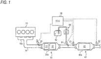
Fig. 1 is a schematic entire configuration view illustrating an exhaust gas purification system of an embodiment. -
Fig. 2 is a functional block diagram illustrating an electronic control unit (ECU) of the embodiment. -
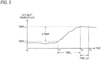
Fig. 3 is a time chart describing low temperature determination, temperature increasing rate determination, decreasing of an amount of urea water being ejected, and prohibition of abnormality diagnosis by the exhaust gas purification system of the embodiment. -
Fig. 4 is a flow chart illustrating an example of control contents by the exhaust gas purification system of the embodiment. - In an exhaust gas purification system of the related art, when an exhaust gas temperature is rapidly increased, (A) of
Fig. 5 is a chart diagram describing a case in which urea water is continuously ejected based on a sensor value of an NOx sensor, and (B) ofFig. 5 is a chart diagram describing a case in which the NOx sensor detects an abnormal value and urea water ejection is stopped. - Hereinafter, an exhaust gas purification system according to an embodiment of the invention will be described based on attached drawings. A same numeral is given to a same component, and a name and a function thereof are the same. Therefore, detailed description thereof is not repeated.
- As illustrated in
Fig. 1 , anexhaust gas passage 11, which derives exhaust gas to the atmosphere, is connected to anexhaust gas manifold 10b of a diesel engine (hereinafter, simply referred to as engine) 10. In theexhaust gas passage 11, a pre-stagepost processing device 30, a post-stagepost processing device 40, and the like are provided sequentially from an upstream side of exhausting. - The pre-stage
post processing device 30 is configured by disposing an oxidation catalyst (hereinafter, DOC) 31 and aDPF 32 sequentially from an upstream side inside acatalyst case 30a. In addition, a fuel ejecting device (fuel addition valve) 33 is provided in theexhaust gas passage 11 of an upstream side than aDOC 31. - The fuel ejecting device 33 ejects an unburned fuel (mainly, HC) inside the
exhaust gas passage 11 according to an instruction signal input from an electronic control unit (hereinafter, ECU) 50. Here, in a case in which post-ejecting due to multi-stage ejection of theengine 10 is used, the fuel ejecting device 33 may be omitted. - For example, the
DOC 31 is formed by carrying a catalyst component on a surface of a ceramic carrier of a cordierite honeycomb structure, or the like. When the HC is supplied by the fuel ejecting device 33 or the post-ejecting, theDOC 31 oxidizes the HC so that an exhaust gas temperature is increased. - For example, the
DPF 32 is formed by disposing a plurality of cells divided using porous partition walls along a flowing direction of exhausting and alternately sealing an upstream side and a downstream side of the cells. TheDPF 32 collects PM in the exhaust gas in fine pores or the surface of the partition walls and also performs so called forced regeneration in which the PM is combusted and removed when the amount of the PM collected reaches a predetermined amount. The forced regeneration is performed by supplying unburned fuel (HC) to theDOC 31 using the fuel ejecting device 33 or by the post-ejecting and increasing the exhaust gas temperature flowing into theDPF 32 to a PM combustion temperature. - The post-stage
post processing device 40 is configured with aSCR 41 accommodated in acase 40a. In addition, a ureawater ejection device 60 and an exhaustgas temperature sensor 21 are provided in theexhaust gas passage 11 on an upstream side than theSCR 41, and theNOx sensor 22 is provided in theexhaust gas passage 11 on a downstream side than theSCR 41. - The urea
water ejection device 60 ejects the urea water which is pressure-transported by aurea water pump 63 from an inside of aurea water tank 62 into theexhaust gas passage 11 of an upstream side than theSCR 41 by opening and closing aurea addition valve 61 according to an instruction signal input from theECU 50. The ejected urea water is hydrolyzed by exhausting heat so as to turn into NH3, and is supplied to theSCR 41 on a downstream side as a reducing agent. - For example, the
SCR 41 is formed by carrying zeolite, or the like on a surface of a ceramic carrier of a honeycomb structure body, or the like, and is configured with the plurality of cells divided by the porous partition wall. TheSCR 41 adsorbs the NH3 supplied as the reducing agent, and selectively reduces and purifies NOx from the exhaust gas being passed using the adsorbed NH3. - The exhaust
gas temperature sensor 21 is an example of exhaust gas temperature acquiring means of the invention, and detects an exhaust gas temperature (hereinafter, SCR inlet temperature TEMPIN) flowing into theSCR 41. TheNOx sensor 22 detects a value of NOx in the exhaust gas (hereinafter, SCR outlet NOx value NOx OUT) passing through theSCR 41. Sensor values ofvarious sensors ECU 50 which is electrically connected. - The
ECU 50 is a section that controls a variety of the devices such as theengine 10, or the fuel ejecting device 33, the ureawater ejection device 60, and is configured with well-known CPU, ROM, RAM, input ports, output ports, and the like. In addition, as illustrated inFig. 2 , the ECU 50 includes a NOx purifyingcontroller 51, a low temperaturestability determining unit 52, a determinationcondition calculating unit 53, a temperature increasingrate calculating unit 54, and a decreasing and prohibitingunit 55 as partial functional elements. In the embodiment, the respective functional elements have described to be included in theECU 50 which is integral hardware, but any part thereof can also be provided in separated hardware. - The NOx purifying
controller 51 feedback-controls the amount of urea water being ejected from the ureawater ejection device 60 based on the SCR outlet NOx value NOxOUT input from theNOx sensor 22. In addition, the NOx purifyingcontroller 51 also performs an abnormality diagnosis of which an alarm is issued when theNOx sensor 22 detects an abnormal value due to significant deterioration of a NOx purifying performance of theSCR 41, failure of theurea addition valve 61, or the like. - The low temperature
stability determining unit 52 determines whether or not the exhaust gas temperature flowing into theSCR 41 is stabled in a predetermined low temperature state based on the SCR inlet temperature TEMPIN input from the exhaustgas temperature sensor 21. In more details, the low temperaturestability determining unit 52 calculates an average temperature TEMP AVE (movement average) within a predetermined period in real time by averaging the SCR inlet temperature TEMPIN detected by the exhaustgas temperature sensor 21 within the predetermined period. In addition, if the calculated average temperature TEMP AVE is equal to or less than a predetermined low temperature determination temperature TEMP 1 (refer to time T0 to T1 ofFig. 3 ), it is determined that the exhaust gas temperature flowing into theSCR 41 is stabled at a low temperature. Here, it is preferable that the low temperature determination temperature TEMP 1 be set within a range of, for example, substantially 190°C to 200°C. - The determination
condition calculating unit 53 calculates (1) a high temperature determining temperature TEMP2, (2) an upper limit temperature increasing rate TEMP% MAX, (3) a longest waiting time TIME UP, and (4) a processing prohibition time TIME ACT which are used for high temperature determination, ejecting amount decreasing ·diagnosing prohibition, or the like to be described later, when the temperature is determined to be stabled at a low temperature by the low temperaturestability determining unit 52. - The high temperature determining temperature TEMP 2 is an exhaust gas temperature right before the NH3 slip occurs in the
SCR 41, and is calculated according to the average temperature TEMP AVE. The upper limit temperature increasing rate TEMP% MAX is an exhaust gas temperature increasing rate where the NH3 slip may occur in theSCR 41, and is calculated according to the average temperature TEMP AVE. A longest waiting time TIME UP is a waiting time for initializing the high temperature determining temperature TEMP 2 in a case in which the exhaust gas temperature does not reach the high temperature determining temperature TEMP 2, and is calculated according to the average temperature TEMP AVE, or is set as an arbitrary time determined in advance. The processing prohibition time TIME ACT is a time for decreasing the amount of urea water being ejected and prohibiting the abnormality diagnosis in order to prevent additional NH3 slip or misdiagnosis at the time of rapidly increasing of the exhaust gas temperature, and is set to be longer as the average temperature TEMP AVE is lower. - The temperature increasing
rate calculating unit 54 calculates a temperature increasing rate when the SCR inlet temperature TEMP IN detected by the exhaustgas temperature sensor 21 is increased from the low temperature determination temperature TEMP 1 to the high temperature determining temperature TEMP 2. In more details, a reaching time TIME 1 (refer to time T1 to T2 ofFig. 3 ) from a timing when the SCR inlet temperature TEMP IN detected by the exhaustgas temperature sensor 21 exceeds the low temperature determination temperature TEMP 1 until it reaches the high temperature determining temperature TEMP 2 is counted by a built-in timer of theECU 50, and a temperature increasing width ΔTEMP of which the low temperature determination temperature TEMP 1 is subtracted from the high temperature determining temperature TEMP 2 is divided by the reaching time TIME 1, and therefore an actual temperature increasing rate TEMP% ACT is calculated. - In a case in which there is a possibility of occurrence of the NH3 slip, the decreasing and prohibiting
unit 55 decreases the amount of urea water being ejected by theNOx purifying controller 51 and prohibits the abnormality diagnosis. In more details, when the actual temperature increasing rate TEMP% ACT calculated by the temperature increasingrate calculating unit 54 is equal to or more than the upper limit temperature increasing rate TEMP% MAX at which there is the possibility of occurrence of the NH3 slip, the decreasing and prohibitingunit 55 decreases the amount of urea water being ejected and prohibits the abnormality diagnosis, from a timing when the SCR inlet temperature TEMP IN exceeds the high temperature determining temperature TEMP 2 until the processing prohibition time TIME ACT elapses (refer to time of T2 to T3Fig. 3 ). Accordingly, the NH3 slip or the misdiagnosis at the time of rapidly increasing the exhaust gas temperature is effectively prevented. - Next, based on
Fig. 4 , a control flow using the exhaust gas purification system of the embodiment will be described. Also, the flow ofFig. 4 , a urea water ejection control and an abnormality diagnosis are performed simultaneously by theNOx purifying controller 51. - In Step (hereinafter, Step is simply disclosed as S) 100, it is determined whether or not the exhaust gas temperature flowing into the
SCR 41 is stabled in a predetermined low temperature state based on the average temperature TEMP AVE which is obtained by taking a moving average of the SCR inlet temperature TEMP IN detected by the exhaustgas temperature sensor 21 within a predetermined period. In a case in which the average temperature TEMP AVE is equal to or less than the low temperature determination temperature TEMP 1 (Yes), the exhaust gas temperature flowing into theSCR 41 is determined to be stabled at a lower temperature, and the control proceeds to S110. - In S110, based on the average temperature TEMP AVE of a low temperature state detected in S100, (1) the high temperature determining temperature TEMP 2 used for high temperature determination, or the like, (2) the upper limit temperature increasing rate TEMP% MAX, (3) the longest waiting time TIME UP, and (4) the processing prohibition time TIME ACT are calculated.
- In S120, it is determined whether or not the SCR inlet temperature TEMPIN detected by the exhaust
gas temperature sensor 21 exceeds the low temperature determination temperature TEMP 1. In a case in which the SCR inlet temperature TEMPIN exceeds the low temperature determination temperature TEMP 1 (Yes), the control proceeds to S130 in which counting using a timer is started. - In S130, it is determined that whether or not the SCR inlet temperature TEMPIN detected by the exhaust
gas temperature sensor 21 reaches the high temperature determining temperature TEMP 2. In a case in which the SCR inlet temperature TEMPIN does not reach the high temperature determining temperature TEMP 2 (No), the control proceeds to S140. - In S140, it is determined that whether or not a counting time TIME 2 of a timer started from S120 reaches the longest waiting time TIME UP. In a case in which the counting time TIME 2 reaches the longest waiting time TIME UP (Yes), the temperature is gradually increased, and thus a possibility of the occurrence of the NH3 slip is low. Therefore, the control proceeds to S300, various determination conditions calculated in S110 are initialized, and returned.
- In S130, in a case in which the SCR inlet temperature TEMPIN reaches the high temperature determining temperature TEMP 2 (Yes), the process proceeds to S200. In S200, by dividing the temperature increasing amount ΔTEMP (= TEMP 2 - TEMP 1) from S120 to S130 by the reaching time TIME 1 counted using the timer, the actual temperature increasing rate TEMP% ACT is calculated.
- In S210, determination of whether or not there is a possibility of occurrence of the NH3 slip in the
SCR 41 due to rapid increasing of temperature is performed. When the actual temperature increasing rate TEMP% ACT calculated in S200 is less than the upper limit temperature increasing rate TEMP% MAX (No), the temperature is gradually increased, and thus a possibility of the occurrence of the NH3 slip is low. Therefore, the control proceeds to S300, various determination conditions calculated in S110 are initialized, and returned. Meanwhile, when the actual temperature increasing rate TEMP% ACT is equal to or more than the upper limit temperature increasing rate TEMP% MAX (Yes), since a possibility of NH3 slip is high, the control proceeds to S220. - In S220, in order to prevent occurrence of excess NH3 slip or misdiagnosis due to rapidly increased temperature, from a timing of S130 until the processing prohibition time TIMEACT elapses, the amount of urea water being ejected by the
NOx purifying controller 51 is decreased and the abnormality diagnosis is prohibited. After that, when the processing prohibition time TIME ACT elapses, the control proceeds to S300, various determination conditions calculated in S110 are initialized, and returned. - Next, effects of the exhaust gas purification system according to the embodiment will be described.
- When the exhaust gas temperature is rapidly increased from a low temperature to a high temperature (refer to time T1 to T2 of (A) of
Fig. 5 ) such as at a time of starting the DPF forced regeneration, the NH3 slip occurs due to deterioration of NH3 adsorbing performance of the SCR 41 (refer to region A of (A) ofFig. 5 ). Since theNOx sensor 22 is not capable of distinguishing NH3 from NOx, in a system in which the amount of urea water being ejected is feedback-controlled based on the sensor value of theNOx sensor 22, a NOx value higher than an actual NOx value may be falsely recognized and the amount of urea water being ejected may be increased (refer to time T2 to T3 of (A) ofFig. 5 ), thereby causing an additional NH3 slip. - In addition, when the excess NH3 slip is generated due to rapid increase in the exhaust gas temperature (refer to region A of (B) of
Fig. 5 ), theNOx sensor 22 which is not capable of distinguishing NH3 from NOx detects an abnormal value (refer to B point of (B) ofFig. 5 ). Therefore, in a system in which the abnormality diagnosis is performed based on the sensor value of theNOx sensor 22, there is a possibility that the NOx is falsely recognized to be excessively discharged, and misdiagnosis such as stop of the urea water ejection (refer to timing T3 of (B) ofFig. 5 ), or issuing an alarm may be performed. - When the actual temperature increasing rate TEMP% ACT, at which the SCR inlet temperature TEMPIN reaches the high temperature determining temperature TEMP 2 from the low temperature determination temperature TEMP 1, is equal to or more than the upper limit temperature increasing rate TEMP% MAX indicating a possibility of the NH3 slip, the exhaust gas purification system of the embodiment is configured to decrease the amount of urea water being ejected and prohibit the abnormality diagnosis until the processing prohibition time TIME ACT elapses. Therefore, it is possible to surely prevent the occurrence of the NH3 slip and misdiagnosis at the time of rapid increasing of the exhaust gas temperature, such as at a time of the DPF forced regeneration. In addition, since excess ejection of the urea water can be prevented, corrosion of an exhausting gas pipe or performance deterioration of the
SCR 41 caused by attaching of the urea water, or the like can be effectively suppressed. - Here, the invention is not limited to the above described embodiment, and appropriately modified and performed without departing from the spirit of the inventions.
- For example, although the amount of urea water being ejected is decreased in a case in which there is a possibility of the NH3 slip, the urea water ejection may be temporarily stopped in a case in which an amount of adsorbing the NH3 of the
SCR 41 is close to the absorbable amount. In addition, theengine 10 is not limited to a diesel engine, and can be widely applied for other internal combustion engines such as a gasoline engine.
Claims (5)
- An exhaust gas purification system comprising:a selective catalytic reduction which is provided on an exhaust gas passage of an internal combustion engine and purifies NOx in exhaust gas by using ammonia generated from urea water as a reducing agent;an NOx sensor which is provided on the exhaust gas passage on downstream side further than the selective catalytic reduction; andcontrol means for controlling an amount of urea water being ejected to the selective catalytic reduction and performing an abnormality diagnosis based on a detection value of the NOx sensor,characterized in that:the exhaust gas purification system comprises:exhaust gas temperature acquiring means for acquiring temperature of the exhaust gas flowing into the selective catalytic reduction;temperature increasing rate calculating means for calculating a temperature increasing rate at which an exhaust gas temperature acquired by the exhaust gas temperature acquiring means reaches a predetermined second temperature, which is higher than a predetermined first temperature, from the first temperature; andprohibiting means for prohibiting the abnormality diagnosis by the control means in a case in which the temperature increasing rate calculated by the temperature increasing rate calculating means is higher than a predetermined determination threshold value.
- The exhaust gas purification system according to claim 1, further comprising:low temperature determination means for calculating an average temperature obtained by averaging exhaust gas temperatures acquired within a predetermined period by the exhaust gas temperature acquiring means, and determining that the temperature is stabled at a low temperature when the average temperature is equal to or less than the first temperature,wherein the temperature increasing rate calculating means starts calculating of the temperature increasing rate when the low temperature determination means determines that the temperature is stabled at a low temperature and the exhaust gas temperature acquired by the exhaust gas temperature acquiring means exceeds the first temperature.
- The exhaust gas purification system according to claim 2, further comprising:decreasing means for decreasing the amount of urea water being ejected by the control means in a case in which the temperature increasing rate calculated by the temperature increasing rate calculating means is higher than a predetermined determination threshold value,wherein the prohibiting means continuously performs prohibition of the abnormality diagnosis for a predetermined period set according to the average temperature, and the decreasing means continuously performs decreasing of the amount of urea water being ejected for the predetermined period set according to the average temperature.
- The exhaust gas purification system according to claim 3,
wherein the prohibiting means does not perform prohibition of the abnormality diagnosis in a case in which the exhaust gas temperature acquired by the exhaust gas temperature acquiring means does not reach the second temperature from the first temperature within a predetermined waiting time, and
wherein the decreasing means does not perform decreasing of the amount of urea water being ejected in a case in which the exhaust gas temperature acquired by the exhaust gas temperature acquiring means does not reach the second temperature from the first temperature within a predetermined waiting time. - The exhaust gas purification system according to any one of claims 1 to 4,
wherein the second temperature is set to a lower temperature than a temperature at which ammonia adsorbed to the selective catalytic reduction is at least partially separated and slipped.
Applications Claiming Priority (2)
| Application Number | Priority Date | Filing Date | Title |
|---|---|---|---|
| JP2014084620A JP6330444B2 (en) | 2014-04-16 | 2014-04-16 | Exhaust purification system |
| PCT/JP2015/061732 WO2015159954A1 (en) | 2014-04-16 | 2015-04-16 | Exhaust gas purification system |
Publications (3)
| Publication Number | Publication Date |
|---|---|
| EP3133257A1 true EP3133257A1 (en) | 2017-02-22 |
| EP3133257A4 EP3133257A4 (en) | 2017-10-18 |
| EP3133257B1 EP3133257B1 (en) | 2018-09-19 |
Family
ID=54324155
Family Applications (1)
| Application Number | Title | Priority Date | Filing Date |
|---|---|---|---|
| EP15780707.4A Active EP3133257B1 (en) | 2014-04-16 | 2015-04-16 | Exhaust gas purification system |
Country Status (5)
| Country | Link |
|---|---|
| US (1) | US9943806B2 (en) |
| EP (1) | EP3133257B1 (en) |
| JP (1) | JP6330444B2 (en) |
| CN (1) | CN106715851B (en) |
| WO (1) | WO2015159954A1 (en) |
Families Citing this family (27)
| Publication number | Priority date | Publication date | Assignee | Title |
|---|---|---|---|---|
| JP2596377B2 (en) | 1994-07-25 | 1997-04-02 | 株式会社大林組 | Scour prevention method for underwater structures |
| WO2016109320A1 (en) | 2014-12-31 | 2016-07-07 | Cummins Emission Solutions, Inc. | Single module integrated aftertreatment module |
| GB2548040B (en) | 2014-12-31 | 2020-11-25 | Cummins Emission Solutions Inc | Compact side inlet and outlet exhaust aftertreatment system |
| CN112901319B (en) | 2014-12-31 | 2022-12-16 | 康明斯排放处理公司 | Closely coupled single module aftertreatment system |
| US10267199B2 (en) | 2015-07-28 | 2019-04-23 | Cummins Emission Solutions Inc. | Angled sensor mount for use with a single module aftertreatment system or the like |
| USD794100S1 (en) | 2015-09-28 | 2017-08-08 | Cummins Emission Solutions Inc. | Aftertreatment system housing |
| ES2828028T3 (en) * | 2015-09-29 | 2021-05-25 | Carrier Corp | Transport refrigeration system comprising a refrigeration unit and a diesel engine |
| JP6731893B2 (en) * | 2017-07-31 | 2020-07-29 | ヤンマーパワーテクノロジー株式会社 | Work vehicle |
| DE102017010825B4 (en) * | 2017-11-23 | 2025-11-13 | Mercedes-Benz Group AG | Method for operating an exhaust system with a first SCR catalyst and a second SCR catalyst |
| KR102518593B1 (en) * | 2018-05-24 | 2023-04-05 | 현대자동차 주식회사 | CORRECTION METHOD OF NOx PURIFYING EFFICIENCY OF SDPF |
| CN112431655A (en) * | 2019-08-26 | 2021-03-02 | 北汽福田汽车股份有限公司 | Vehicle aftertreatment system abnormality determination method and device, storage medium and vehicle |
| US11760169B2 (en) | 2020-08-20 | 2023-09-19 | Denso International America, Inc. | Particulate control systems and methods for olfaction sensors |
| US12269315B2 (en) | 2020-08-20 | 2025-04-08 | Denso International America, Inc. | Systems and methods for measuring and managing odor brought into rental vehicles |
| US11636870B2 (en) | 2020-08-20 | 2023-04-25 | Denso International America, Inc. | Smoking cessation systems and methods |
| US12017506B2 (en) | 2020-08-20 | 2024-06-25 | Denso International America, Inc. | Passenger cabin air control systems and methods |
| US12251991B2 (en) | 2020-08-20 | 2025-03-18 | Denso International America, Inc. | Humidity control for olfaction sensors |
| US11881093B2 (en) | 2020-08-20 | 2024-01-23 | Denso International America, Inc. | Systems and methods for identifying smoking in vehicles |
| US11813926B2 (en) | 2020-08-20 | 2023-11-14 | Denso International America, Inc. | Binding agent and olfaction sensor |
| US11932080B2 (en) | 2020-08-20 | 2024-03-19 | Denso International America, Inc. | Diagnostic and recirculation control systems and methods |
| US11760170B2 (en) | 2020-08-20 | 2023-09-19 | Denso International America, Inc. | Olfaction sensor preservation systems and methods |
| US12377711B2 (en) | 2020-08-20 | 2025-08-05 | Denso International America, Inc. | Vehicle feature control systems and methods based on smoking |
| US11828210B2 (en) | 2020-08-20 | 2023-11-28 | Denso International America, Inc. | Diagnostic systems and methods of vehicles using olfaction |
| CN112814770B (en) * | 2020-12-31 | 2022-04-05 | 潍柴动力股份有限公司 | Uniformity evaluation method and device of parallel SCR system |
| CN114046197B (en) * | 2021-10-11 | 2023-03-21 | 潍柴动力股份有限公司 | Method and device for treating waste gas and readable storage medium |
| CN116220869B (en) * | 2022-12-08 | 2025-09-19 | 潍柴动力股份有限公司 | Control method and control device of urea injection system and urea injection system |
| CN117386495B (en) * | 2023-11-27 | 2024-11-05 | 一汽解放汽车有限公司 | Fault diagnosis method, device and equipment for nitrogen oxide sensor of vehicle |
| CN119616636B (en) * | 2024-12-09 | 2025-09-12 | 东风商用车有限公司 | Abnormal urea consumption analysis method, device and vehicle |
Family Cites Families (15)
| Publication number | Priority date | Publication date | Assignee | Title |
|---|---|---|---|---|
| JP2003293738A (en) | 2002-03-29 | 2003-10-15 | Mitsubishi Fuso Truck & Bus Corp | NOx CLEANING DEVICE FOR INTERNAL COMBUSTION ENGINE |
| JP2006242094A (en) * | 2005-03-03 | 2006-09-14 | Hino Motors Ltd | Exhaust purification device |
| JP4542455B2 (en) * | 2005-03-28 | 2010-09-15 | 三菱ふそうトラック・バス株式会社 | Exhaust gas purification device for internal combustion engine |
| JP4592504B2 (en) * | 2005-06-09 | 2010-12-01 | 三菱ふそうトラック・バス株式会社 | Exhaust purification device |
| DE602007005125D1 (en) * | 2007-07-31 | 2010-04-15 | Delphi Tech Inc | r catalytic reduction |
| FR2931201B1 (en) * | 2008-05-16 | 2010-06-04 | Peugeot Citroen Automobiles Sa | METHOD OF CORRECTING NITROGEN OXIDE EMISSION MODELS |
| EP2123345B1 (en) * | 2008-05-23 | 2010-08-04 | Umicore AG & Co. KG | Device for cleaning diesel exhaust gases |
| KR100962871B1 (en) * | 2008-06-10 | 2010-06-09 | 현대자동차주식회사 | CO2 Absorbent Regeneration Method |
| US8539757B2 (en) * | 2009-01-16 | 2013-09-24 | Toyota Jidosha Kabushiki Kaisha | Exhaust purification apparatus for internal combustion engine |
| JP2010180847A (en) | 2009-02-09 | 2010-08-19 | Toyota Motor Corp | Failure diagnosis device of exhaust emission control system |
| JP5252217B2 (en) * | 2009-04-10 | 2013-07-31 | マツダ株式会社 | Engine exhaust purification system |
| JP2012036835A (en) * | 2010-08-06 | 2012-02-23 | Mitsubishi Fuso Truck & Bus Corp | Exhaust emission control device |
| SE536083C2 (en) | 2011-08-31 | 2013-04-30 | Scania Cv Ab | A method of detecting reducing agent crystals in an SCR system and corresponding SCR system |
| JP2013181411A (en) | 2012-02-29 | 2013-09-12 | Toyota Motor Corp | Exhaust emission control device of internal combustion engine |
| RU2597380C1 (en) * | 2012-12-06 | 2016-09-10 | Тойота Дзидося Кабусики Кайся | System for determining failures of exhaust gas cleaning device |
-
2014
- 2014-04-16 JP JP2014084620A patent/JP6330444B2/en not_active Expired - Fee Related
-
2015
- 2015-04-16 US US15/304,828 patent/US9943806B2/en active Active
- 2015-04-16 EP EP15780707.4A patent/EP3133257B1/en active Active
- 2015-04-16 WO PCT/JP2015/061732 patent/WO2015159954A1/en not_active Ceased
- 2015-04-16 CN CN201580020025.0A patent/CN106715851B/en active Active
Also Published As
| Publication number | Publication date |
|---|---|
| JP2015203399A (en) | 2015-11-16 |
| US9943806B2 (en) | 2018-04-17 |
| US20170043295A1 (en) | 2017-02-16 |
| EP3133257A4 (en) | 2017-10-18 |
| CN106715851A (en) | 2017-05-24 |
| JP6330444B2 (en) | 2018-05-30 |
| WO2015159954A1 (en) | 2015-10-22 |
| CN106715851B (en) | 2019-05-10 |
| EP3133257B1 (en) | 2018-09-19 |
Similar Documents
| Publication | Publication Date | Title |
|---|---|---|
| EP3133257B1 (en) | Exhaust gas purification system | |
| EP3141717B1 (en) | Exhaust purification system | |
| JP6087580B2 (en) | Exhaust purification device for internal combustion engine and exhaust purification method thereof | |
| JP5170689B2 (en) | Exhaust gas purification device for internal combustion engine | |
| CN110637149A (en) | Engine and its control method | |
| JP6264048B2 (en) | Injection control device | |
| EP3135875B1 (en) | Exhaust purifying system | |
| EP2392791A1 (en) | Exhaust purifying device | |
| EP3068988B1 (en) | Exhaust gas control apparatus and exhaust gas control method for engine | |
| EP3056701B1 (en) | Exhaust purification system | |
| JP6398402B2 (en) | Exhaust purification system | |
| CN111502843A (en) | Aftertreatment system and aftertreatment method for a lean burn engine | |
| JP6398401B2 (en) | Exhaust purification system | |
| WO2018230521A1 (en) | Exhaust gas purification system and deposition amount estimation method | |
| JP2017145755A (en) | Exhaust purification system | |
| JP2015068815A (en) | Detection device | |
| PH12018000215A1 (en) | Exhaust gas cleaning system |
Legal Events
| Date | Code | Title | Description |
|---|---|---|---|
| STAA | Information on the status of an ep patent application or granted ep patent |
Free format text: STATUS: THE INTERNATIONAL PUBLICATION HAS BEEN MADE |
|
| PUAI | Public reference made under article 153(3) epc to a published international application that has entered the european phase |
Free format text: ORIGINAL CODE: 0009012 |
|
| STAA | Information on the status of an ep patent application or granted ep patent |
Free format text: STATUS: REQUEST FOR EXAMINATION WAS MADE |
|
| 17P | Request for examination filed |
Effective date: 20161116 |
|
| AK | Designated contracting states |
Kind code of ref document: A1 Designated state(s): AL AT BE BG CH CY CZ DE DK EE ES FI FR GB GR HR HU IE IS IT LI LT LU LV MC MK MT NL NO PL PT RO RS SE SI SK SM TR |
|
| AX | Request for extension of the european patent |
Extension state: BA ME |
|
| DAV | Request for validation of the european patent (deleted) | ||
| DAX | Request for extension of the european patent (deleted) | ||
| A4 | Supplementary search report drawn up and despatched |
Effective date: 20170920 |
|
| RIC1 | Information provided on ipc code assigned before grant |
Ipc: B01D 53/94 20060101ALI20170914BHEP Ipc: F01N 3/20 20060101ALI20170914BHEP Ipc: F01N 3/08 20060101AFI20170914BHEP |
|
| GRAP | Despatch of communication of intention to grant a patent |
Free format text: ORIGINAL CODE: EPIDOSNIGR1 |
|
| STAA | Information on the status of an ep patent application or granted ep patent |
Free format text: STATUS: GRANT OF PATENT IS INTENDED |
|
| RIC1 | Information provided on ipc code assigned before grant |
Ipc: F01N 11/00 20060101ALI20180319BHEP Ipc: B01D 53/94 20060101ALI20180319BHEP Ipc: F01N 3/20 20060101ALI20180319BHEP Ipc: F01N 3/08 20060101AFI20180319BHEP |
|
| INTG | Intention to grant announced |
Effective date: 20180420 |
|
| GRAS | Grant fee paid |
Free format text: ORIGINAL CODE: EPIDOSNIGR3 |
|
| GRAA | (expected) grant |
Free format text: ORIGINAL CODE: 0009210 |
|
| STAA | Information on the status of an ep patent application or granted ep patent |
Free format text: STATUS: THE PATENT HAS BEEN GRANTED |
|
| AK | Designated contracting states |
Kind code of ref document: B1 Designated state(s): AL AT BE BG CH CY CZ DE DK EE ES FI FR GB GR HR HU IE IS IT LI LT LU LV MC MK MT NL NO PL PT RO RS SE SI SK SM TR |
|
| REG | Reference to a national code |
Ref country code: GB Ref legal event code: FG4D |
|
| REG | Reference to a national code |
Ref country code: CH Ref legal event code: EP |
|
| REG | Reference to a national code |
Ref country code: AT Ref legal event code: REF Ref document number: 1043498 Country of ref document: AT Kind code of ref document: T Effective date: 20181015 |
|
| REG | Reference to a national code |
Ref country code: IE Ref legal event code: FG4D |
|
| REG | Reference to a national code |
Ref country code: DE Ref legal event code: R096 Ref document number: 602015016712 Country of ref document: DE |
|
| REG | Reference to a national code |
Ref country code: NL Ref legal event code: MP Effective date: 20180919 |
|
| PG25 | Lapsed in a contracting state [announced via postgrant information from national office to epo] |
Ref country code: NO Free format text: LAPSE BECAUSE OF FAILURE TO SUBMIT A TRANSLATION OF THE DESCRIPTION OR TO PAY THE FEE WITHIN THE PRESCRIBED TIME-LIMIT Effective date: 20181219 Ref country code: FI Free format text: LAPSE BECAUSE OF FAILURE TO SUBMIT A TRANSLATION OF THE DESCRIPTION OR TO PAY THE FEE WITHIN THE PRESCRIBED TIME-LIMIT Effective date: 20180919 Ref country code: LT Free format text: LAPSE BECAUSE OF FAILURE TO SUBMIT A TRANSLATION OF THE DESCRIPTION OR TO PAY THE FEE WITHIN THE PRESCRIBED TIME-LIMIT Effective date: 20180919 Ref country code: RS Free format text: LAPSE BECAUSE OF FAILURE TO SUBMIT A TRANSLATION OF THE DESCRIPTION OR TO PAY THE FEE WITHIN THE PRESCRIBED TIME-LIMIT Effective date: 20180919 Ref country code: SE Free format text: LAPSE BECAUSE OF FAILURE TO SUBMIT A TRANSLATION OF THE DESCRIPTION OR TO PAY THE FEE WITHIN THE PRESCRIBED TIME-LIMIT Effective date: 20180919 Ref country code: BG Free format text: LAPSE BECAUSE OF FAILURE TO SUBMIT A TRANSLATION OF THE DESCRIPTION OR TO PAY THE FEE WITHIN THE PRESCRIBED TIME-LIMIT Effective date: 20181219 Ref country code: GR Free format text: LAPSE BECAUSE OF FAILURE TO SUBMIT A TRANSLATION OF THE DESCRIPTION OR TO PAY THE FEE WITHIN THE PRESCRIBED TIME-LIMIT Effective date: 20181220 |
|
| REG | Reference to a national code |
Ref country code: LT Ref legal event code: MG4D |
|
| PG25 | Lapsed in a contracting state [announced via postgrant information from national office to epo] |
Ref country code: AL Free format text: LAPSE BECAUSE OF FAILURE TO SUBMIT A TRANSLATION OF THE DESCRIPTION OR TO PAY THE FEE WITHIN THE PRESCRIBED TIME-LIMIT Effective date: 20180919 Ref country code: HR Free format text: LAPSE BECAUSE OF FAILURE TO SUBMIT A TRANSLATION OF THE DESCRIPTION OR TO PAY THE FEE WITHIN THE PRESCRIBED TIME-LIMIT Effective date: 20180919 Ref country code: LV Free format text: LAPSE BECAUSE OF FAILURE TO SUBMIT A TRANSLATION OF THE DESCRIPTION OR TO PAY THE FEE WITHIN THE PRESCRIBED TIME-LIMIT Effective date: 20180919 |
|
| REG | Reference to a national code |
Ref country code: AT Ref legal event code: MK05 Ref document number: 1043498 Country of ref document: AT Kind code of ref document: T Effective date: 20180919 |
|
| PG25 | Lapsed in a contracting state [announced via postgrant information from national office to epo] |
Ref country code: AT Free format text: LAPSE BECAUSE OF FAILURE TO SUBMIT A TRANSLATION OF THE DESCRIPTION OR TO PAY THE FEE WITHIN THE PRESCRIBED TIME-LIMIT Effective date: 20180919 Ref country code: NL Free format text: LAPSE BECAUSE OF FAILURE TO SUBMIT A TRANSLATION OF THE DESCRIPTION OR TO PAY THE FEE WITHIN THE PRESCRIBED TIME-LIMIT Effective date: 20180919 Ref country code: ES Free format text: LAPSE BECAUSE OF FAILURE TO SUBMIT A TRANSLATION OF THE DESCRIPTION OR TO PAY THE FEE WITHIN THE PRESCRIBED TIME-LIMIT Effective date: 20180919 Ref country code: PL Free format text: LAPSE BECAUSE OF FAILURE TO SUBMIT A TRANSLATION OF THE DESCRIPTION OR TO PAY THE FEE WITHIN THE PRESCRIBED TIME-LIMIT Effective date: 20180919 Ref country code: IS Free format text: LAPSE BECAUSE OF FAILURE TO SUBMIT A TRANSLATION OF THE DESCRIPTION OR TO PAY THE FEE WITHIN THE PRESCRIBED TIME-LIMIT Effective date: 20190119 Ref country code: RO Free format text: LAPSE BECAUSE OF FAILURE TO SUBMIT A TRANSLATION OF THE DESCRIPTION OR TO PAY THE FEE WITHIN THE PRESCRIBED TIME-LIMIT Effective date: 20180919 Ref country code: IT Free format text: LAPSE BECAUSE OF FAILURE TO SUBMIT A TRANSLATION OF THE DESCRIPTION OR TO PAY THE FEE WITHIN THE PRESCRIBED TIME-LIMIT Effective date: 20180919 Ref country code: CZ Free format text: LAPSE BECAUSE OF FAILURE TO SUBMIT A TRANSLATION OF THE DESCRIPTION OR TO PAY THE FEE WITHIN THE PRESCRIBED TIME-LIMIT Effective date: 20180919 Ref country code: EE Free format text: LAPSE BECAUSE OF FAILURE TO SUBMIT A TRANSLATION OF THE DESCRIPTION OR TO PAY THE FEE WITHIN THE PRESCRIBED TIME-LIMIT Effective date: 20180919 |
|
| PG25 | Lapsed in a contracting state [announced via postgrant information from national office to epo] |
Ref country code: SM Free format text: LAPSE BECAUSE OF FAILURE TO SUBMIT A TRANSLATION OF THE DESCRIPTION OR TO PAY THE FEE WITHIN THE PRESCRIBED TIME-LIMIT Effective date: 20180919 Ref country code: SK Free format text: LAPSE BECAUSE OF FAILURE TO SUBMIT A TRANSLATION OF THE DESCRIPTION OR TO PAY THE FEE WITHIN THE PRESCRIBED TIME-LIMIT Effective date: 20180919 Ref country code: PT Free format text: LAPSE BECAUSE OF FAILURE TO SUBMIT A TRANSLATION OF THE DESCRIPTION OR TO PAY THE FEE WITHIN THE PRESCRIBED TIME-LIMIT Effective date: 20190119 |
|
| REG | Reference to a national code |
Ref country code: DE Ref legal event code: R097 Ref document number: 602015016712 Country of ref document: DE |
|
| PLBE | No opposition filed within time limit |
Free format text: ORIGINAL CODE: 0009261 |
|
| STAA | Information on the status of an ep patent application or granted ep patent |
Free format text: STATUS: NO OPPOSITION FILED WITHIN TIME LIMIT |
|
| PG25 | Lapsed in a contracting state [announced via postgrant information from national office to epo] |
Ref country code: DK Free format text: LAPSE BECAUSE OF FAILURE TO SUBMIT A TRANSLATION OF THE DESCRIPTION OR TO PAY THE FEE WITHIN THE PRESCRIBED TIME-LIMIT Effective date: 20180919 |
|
| 26N | No opposition filed |
Effective date: 20190620 |
|
| PG25 | Lapsed in a contracting state [announced via postgrant information from national office to epo] |
Ref country code: SI Free format text: LAPSE BECAUSE OF FAILURE TO SUBMIT A TRANSLATION OF THE DESCRIPTION OR TO PAY THE FEE WITHIN THE PRESCRIBED TIME-LIMIT Effective date: 20180919 |
|
| REG | Reference to a national code |
Ref country code: CH Ref legal event code: PL |
|
| REG | Reference to a national code |
Ref country code: BE Ref legal event code: MM Effective date: 20190430 |
|
| PG25 | Lapsed in a contracting state [announced via postgrant information from national office to epo] |
Ref country code: LU Free format text: LAPSE BECAUSE OF NON-PAYMENT OF DUE FEES Effective date: 20190416 Ref country code: MC Free format text: LAPSE BECAUSE OF FAILURE TO SUBMIT A TRANSLATION OF THE DESCRIPTION OR TO PAY THE FEE WITHIN THE PRESCRIBED TIME-LIMIT Effective date: 20180919 |
|
| PG25 | Lapsed in a contracting state [announced via postgrant information from national office to epo] |
Ref country code: CH Free format text: LAPSE BECAUSE OF NON-PAYMENT OF DUE FEES Effective date: 20190430 Ref country code: LI Free format text: LAPSE BECAUSE OF NON-PAYMENT OF DUE FEES Effective date: 20190430 |
|
| PG25 | Lapsed in a contracting state [announced via postgrant information from national office to epo] |
Ref country code: BE Free format text: LAPSE BECAUSE OF NON-PAYMENT OF DUE FEES Effective date: 20190430 |
|
| PG25 | Lapsed in a contracting state [announced via postgrant information from national office to epo] |
Ref country code: TR Free format text: LAPSE BECAUSE OF FAILURE TO SUBMIT A TRANSLATION OF THE DESCRIPTION OR TO PAY THE FEE WITHIN THE PRESCRIBED TIME-LIMIT Effective date: 20180919 |
|
| PG25 | Lapsed in a contracting state [announced via postgrant information from national office to epo] |
Ref country code: IE Free format text: LAPSE BECAUSE OF NON-PAYMENT OF DUE FEES Effective date: 20190416 |
|
| PG25 | Lapsed in a contracting state [announced via postgrant information from national office to epo] |
Ref country code: CY Free format text: LAPSE BECAUSE OF FAILURE TO SUBMIT A TRANSLATION OF THE DESCRIPTION OR TO PAY THE FEE WITHIN THE PRESCRIBED TIME-LIMIT Effective date: 20180919 |
|
| PG25 | Lapsed in a contracting state [announced via postgrant information from national office to epo] |
Ref country code: MT Free format text: LAPSE BECAUSE OF FAILURE TO SUBMIT A TRANSLATION OF THE DESCRIPTION OR TO PAY THE FEE WITHIN THE PRESCRIBED TIME-LIMIT Effective date: 20180919 Ref country code: HU Free format text: LAPSE BECAUSE OF FAILURE TO SUBMIT A TRANSLATION OF THE DESCRIPTION OR TO PAY THE FEE WITHIN THE PRESCRIBED TIME-LIMIT; INVALID AB INITIO Effective date: 20150416 |
|
| PG25 | Lapsed in a contracting state [announced via postgrant information from national office to epo] |
Ref country code: MK Free format text: LAPSE BECAUSE OF FAILURE TO SUBMIT A TRANSLATION OF THE DESCRIPTION OR TO PAY THE FEE WITHIN THE PRESCRIBED TIME-LIMIT Effective date: 20180919 |
|
| PGFP | Annual fee paid to national office [announced via postgrant information from national office to epo] |
Ref country code: FR Payment date: 20230309 Year of fee payment: 9 |
|
| PGFP | Annual fee paid to national office [announced via postgrant information from national office to epo] |
Ref country code: GB Payment date: 20230302 Year of fee payment: 9 |
|
| REG | Reference to a national code |
Ref country code: DE Ref legal event code: R082 Ref document number: 602015016712 Country of ref document: DE Representative=s name: MEISSNER BOLTE PATENTANWAELTE RECHTSANWAELTE P, DE |
|
| GBPC | Gb: european patent ceased through non-payment of renewal fee |
Effective date: 20240416 |
|
| PG25 | Lapsed in a contracting state [announced via postgrant information from national office to epo] |
Ref country code: GB Free format text: LAPSE BECAUSE OF NON-PAYMENT OF DUE FEES Effective date: 20240416 |
|
| PG25 | Lapsed in a contracting state [announced via postgrant information from national office to epo] |
Ref country code: FR Free format text: LAPSE BECAUSE OF NON-PAYMENT OF DUE FEES Effective date: 20240430 |
|
| PG25 | Lapsed in a contracting state [announced via postgrant information from national office to epo] |
Ref country code: GB Free format text: LAPSE BECAUSE OF NON-PAYMENT OF DUE FEES Effective date: 20240416 Ref country code: FR Free format text: LAPSE BECAUSE OF NON-PAYMENT OF DUE FEES Effective date: 20240430 |
|
| PGFP | Annual fee paid to national office [announced via postgrant information from national office to epo] |
Ref country code: DE Payment date: 20250319 Year of fee payment: 11 |