EP3133025A1 - Support structure for supporting a big-bag - Google Patents
Support structure for supporting a big-bag Download PDFInfo
- Publication number
- EP3133025A1 EP3133025A1 EP15182054.5A EP15182054A EP3133025A1 EP 3133025 A1 EP3133025 A1 EP 3133025A1 EP 15182054 A EP15182054 A EP 15182054A EP 3133025 A1 EP3133025 A1 EP 3133025A1
- Authority
- EP
- European Patent Office
- Prior art keywords
- frame
- support structure
- barrier
- top support
- structure according
- Prior art date
- Legal status (The legal status is an assumption and is not a legal conclusion. Google has not performed a legal analysis and makes no representation as to the accuracy of the status listed.)
- Withdrawn
Links
Images


Classifications
-
- B—PERFORMING OPERATIONS; TRANSPORTING
- B65—CONVEYING; PACKING; STORING; HANDLING THIN OR FILAMENTARY MATERIAL
- B65D—CONTAINERS FOR STORAGE OR TRANSPORT OF ARTICLES OR MATERIALS, e.g. BAGS, BARRELS, BOTTLES, BOXES, CANS, CARTONS, CRATES, DRUMS, JARS, TANKS, HOPPERS, FORWARDING CONTAINERS; ACCESSORIES, CLOSURES, OR FITTINGS THEREFOR; PACKAGING ELEMENTS; PACKAGES
- B65D19/00—Pallets or like platforms, with or without side walls, for supporting loads to be lifted or lowered
- B65D19/38—Details or accessories
- B65D19/385—Frames, corner posts or pallet converters, e.g. for facilitating stacking of charged pallets
Definitions
- the invention relates to a support structure for supporting a big-bag, which support structure comprises:
- Such a support structure is for example known from the earlier European patent application no. 14163645.6 of the applicant.
- the known support structures are positioned with the U-shaped base frame around a big-bag, such that the top support frame is positioned above the big-bag. This allows for a second big-bag to be supported over the first big-bag.
- other heavy goods such as pallets with products, can be positioned at two levels above each other.
- the known support structure is very suitable for static applications.
- the big-bags or the like are to be transported by truck, only one layer of big-bags can be placed in the trailer.
- the height of a trailer is typically substantially larger, than the height of a big-bag, often more than two times said height, and as the loading capacity of a trailer is sufficiently large, one could consider to use the known support structures inside of the trailer to be able to load a second layer of big-bags over the first layer.
- the application of said known support structures in a trailer is however a dynamic application.
- the big-bags inside of the trailer need to be securely fastened or otherwise the big-bags will slide towards the front of the truck.
- the big-bags on the floor of the trailer will keep their position due to shape of the floor and surrounding upstanding walls or the like.
- the big-bags on the second level will however easily slide of the support structures, especially when the big-bags on the second level are only positioned over the rear axles of the trailer due to the required weight distribution. In such a case, the big-bags on the second level will not be constrained by the upstanding walls, especially the front wall of the trailer.
- a support structure according to the preamble, which support structure is characterized by a barrier frame arranged to a first side of the top support frame and extending vertically upward.
- the barrier frame prevents any cargo placed on top of the support structure to shift off the top support frame over the first side, when for example a truck transporting the support structures has to brake. It is obvious that the supporting structure has to be positioned in such a case with the first side towards the front of the truck.
- the barrier frame has a fence-like structure.
- the fence-like structure minimizes the weight, while a large barrier surface is provided to prevent cargo to shift off the top support frame.
- the barrier frame is hingedly arranged to the first side of the top support frame and movable between a horizontal position, in which the barrier frame is parallel to and rests on the top support frame and a vertical position, in which the barrier frame is perpendicular to the top support frame.
- the barrier frame By arranging the barrier frame along a hinge to the top support frame, it is possible to pivot the barrier frame from a vertical to a horizontal position.
- the supporting frame In the horizontal position, the supporting frame can easily be stacked on top of other supporting frames of the invention. Also in the horizontal position, the cargo, such as big-bags supported on the top support frame can be taken off from any direction. This is in particular useful, when the supporting frames are used in a stationary application, such as in a storage hall.
- the top support frame comprises a first frame tube with square cross-section arranged along the first side and wherein the barrier frame comprises a second frame tube with square cross-section, the second frame tube being parallel to and arranged to the first frame tube.
- the flat surfaces of frame tubes with square cross-section provides good support surfaces for the barrier frame to be supported on the op support frame at the hinge ares. Also, when such frame tubes are used for the remaining support structure, the resulting support structures can be stacked more reliably, as the flat tube surfaces provide a relative large support area.
- the hinge axis is arranged along the outer periphery of the top support frame at the first frame tube and the second frame tube hinges in the vertical position of the barrier frame to a position, in vertical projection, outside of the outer periphery of the top support frame.
- the full surface of the top support frame can be used for supporting a big-bag or other goods.
- a first locking part is arranged to one of the top support frame and the barrier frame and a second locking part is arranged to the other of the top support frame and the barrier frame.
- the first locking part is a protruding lip with a hole
- the second locking part is a pin
- the pin extends through the hole of the protruding lip in the vertical position of the barrier frame for locking the barrier frame in said vertical position.
- the barrier frame can be locked in the vertical position.
- the barrier frame cannot unexpectedly, for example when the big-bag touches the barrier frame, hinge back to the horizontal position.
- the height of the barrier frame in the vertical position is at least equal to half the length of the uprights.
- the barrier frame prevents goods to shift off the top support frame, but also prevents that the goods topple over the barrier frame.
- the first side of the top support frame is positioned, in vertical projection, on the opening of the U-shaped base frame.
- a support structure can easily be slid from the back of the trailer over a big-bag, or the like, already loaded into the trailer.
- the barrier frame can then be tilted to the vertical position, such that the barrier frame is positioned in front of the support structure, to prevent any shifting of cargo placed on the support structure when the trailer is braking hard.
- the support structure according to the invention further comprises a number of cross linked pull bars arranged between adjacent uprights, when seen along the path of the U-shaped base frame.
- the cross linked pull bars provide for additional strength and stability.
- the support structure is nestable. This allows for compact storage of a number of support structures, when the support structures are not used.
- the support structure according to the invention comprises brackets arranged on opposite sides of and on the bottom of the top support frame to provide loops in which the spoons of a forklift can be inserted for lifting a support structure from a stack of support structures according to the invention.
- the top support frames of the stacked support structures could be too close together for the spoons of a forklift to be inserted under a top support frame in order to lift one support structure from the stack.
- the brackets provide for a spacer between adjacent support structures, such that at least a minimum space is always present for the spoons to be inserted. This prevents any damage to the support structures, which are typically galvanized to prevent rusting.
- Figure 1 shows a cross-sectional view of a trailer 1 of a truck.
- the trailer 1 has floor 2, on which a number of pallets 3 with big-bags 4 are placed.
- a second layer of pallets 5 with big-bags 6 is arranged over the first layer of pallets 3 and big-bags 4.
- the second row of pallets 5 with big-bags is supported by support structures 7.
- FIG. 2 shows a perspective view of a first embodiment of a support structure 7 according to the invention.
- the support structure 7 has a U-shaped base frame 8, a top support frame 9 and a number of uprights 10 extending between the U-shaped base frame 8 and top support frame 9.
- the uprights 10 are reinforced by cross-linked pull bars 11.
- a barrier frame 12 is arranged on a first side of the top support frame 9. This barrier frame 12 is positioned, in vertical projection, on the opening of the U-shaped base frame 8.
- the barrier frame 12 has feet 13, which extend into brackets 14 arranged on the first side of the top support frame 9, such that the barrier frame 12 can be removed when desired.
- the width of the top support frame 9 is smaller than the width of the U-shaped base frame 8, such that the support structures 7 are nestable.
- FIG. 3 shows a perspective view of a second embodiment 20 of a support structure according to the invention.
- the support structure 20 has a U-shaped base frame 21, a top support frame 22 and uprights 23 extending between the U-shaped base frame 21 and the top support frame 22.
- the support structure 20 is shifted over a pallet 3 with a big-bag 4, such that a second big-bag (not shown) can be placed on top of the top support frame 22.
- Brackets 24 are arranged under the top support frame 22 to provide loops in which the spoons of a forklift can be inserted to lift the support structure 20.
- a barrier frame 26 is hingedly arranged at the first side 25 of the top support frame 22. This allows for the barrier frame 26 to lie flat on the top support frame 22 or to stand vertically up for preventing goods sliding off the top support frame 22.
- Figures 4A and 4B show a detail of a first variant 30 of the second embodiment of figure 3 .
- the top support frame 22 has a first frame tube 31 with square cross-section arranged along the first side 25.
- the barrier frame 26 has a second frame tube 32 with square cross-section.
- the first frame tube 31 and the second frame tube 32 are hinged along the hinge axis 33.
- the hinge axis 33 is positioned on the outer periphery of the top support frame 22, the barrier frame 26 will hinge outside of the periphery, when seen in vertical projection, and as shown in figure 4B . This allows for the full top surface of the top support frame 22 to be used for supporting a second pallet with big-bag.
- the stubs 34 ensure that the barrier frame 26 does not hinge past the vertical position as shown in figure 4B .
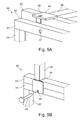
- Figures 5A and 5B show a detail of a second variant 40 of the second embodiment of figure 3 .
- the top support frame 22 has also a first frame tube 41 with square cross-section arranged along the first side 25.
- the barrier frame 26 has a second frame tube 42 with square cross-section.
- the first frame tube 41 and the second frame tube 42 are hinged along the hinge axis 43.
- a locking plate 44 with a hole 45 is attached to the second frame tube 42.
- a hole 46 is furthermore provided in the first frame tube 41.
- the locking plate 44 In vertical position of the barrier frame 26 (as shown in figure 5B ), the locking plate 44 lies against the first frame tube 41. By inserting a pin 46 into the hole 45 of the locking plate 44 and the hole 47, the barrier frame 26 can be locked in its vertical position.
Abstract
- a U-shaped base frame (8);
- a top support frame (9); and
- a number of uprights (10) extending vertically from the base frame (8) to the top support frame (9), and
- a barrier frame (12) arranged to a first side of the top support frame (9) and extending vertically upward.
Description
- The invention relates to a support structure for supporting a big-bag, which support structure comprises:
- a U-shaped base frame;
- a top support frame; and
- a number of uprights extending vertically from the base frame to the top support frame.
- Such a support structure is for example known from the earlier European patent application no.
14163645.6 - The known support structure is very suitable for static applications. However, when the big-bags or the like are to be transported by truck, only one layer of big-bags can be placed in the trailer. As the height of a trailer is typically substantially larger, than the height of a big-bag, often more than two times said height, and as the loading capacity of a trailer is sufficiently large, one could consider to use the known support structures inside of the trailer to be able to load a second layer of big-bags over the first layer.
- The application of said known support structures in a trailer is however a dynamic application. When the truck has to brake hard, the big-bags inside of the trailer need to be securely fastened or otherwise the big-bags will slide towards the front of the truck. Typically, the big-bags on the floor of the trailer will keep their position due to shape of the floor and surrounding upstanding walls or the like. The big-bags on the second level will however easily slide of the support structures, especially when the big-bags on the second level are only positioned over the rear axles of the trailer due to the required weight distribution. In such a case, the big-bags on the second level will not be constrained by the upstanding walls, especially the front wall of the trailer.
- It is accordingly an object to reduce the above mentioned disadvantages.
- This object is achieved according to the invention with a support structure according to the preamble, which support structure is characterized by a barrier frame arranged to a first side of the top support frame and extending vertically upward.
- The barrier frame prevents any cargo placed on top of the support structure to shift off the top support frame over the first side, when for example a truck transporting the support structures has to brake. It is obvious that the supporting structure has to be positioned in such a case with the first side towards the front of the truck.
- Preferably, the barrier frame has a fence-like structure. The fence-like structure minimizes the weight, while a large barrier surface is provided to prevent cargo to shift off the top support frame.
- In a preferred embodiment of the support structure according to the invention the barrier frame is hingedly arranged to the first side of the top support frame and movable between a horizontal position, in which the barrier frame is parallel to and rests on the top support frame and a vertical position, in which the barrier frame is perpendicular to the top support frame.
- By arranging the barrier frame along a hinge to the top support frame, it is possible to pivot the barrier frame from a vertical to a horizontal position. In the horizontal position, the supporting frame can easily be stacked on top of other supporting frames of the invention. Also in the horizontal position, the cargo, such as big-bags supported on the top support frame can be taken off from any direction. This is in particular useful, when the supporting frames are used in a stationary application, such as in a storage hall.
- In another embodiment of the support structure according to the invention the top support frame comprises a first frame tube with square cross-section arranged along the first side and wherein the barrier frame comprises a second frame tube with square cross-section, the second frame tube being parallel to and arranged to the first frame tube.
- The flat surfaces of frame tubes with square cross-section provides good support surfaces for the barrier frame to be supported on the op support frame at the hinge ares. Also, when such frame tubes are used for the remaining support structure, the resulting support structures can be stacked more reliably, as the flat tube surfaces provide a relative large support area.
- In another preferred embodiment of the support structure according to the invention, the hinge axis is arranged along the outer periphery of the top support frame at the first frame tube and the second frame tube hinges in the vertical position of the barrier frame to a position, in vertical projection, outside of the outer periphery of the top support frame.
- By having the second frame tube hinging in the vertical projection outside of the outer periphery of the top support frame, the full surface of the top support frame can be used for supporting a big-bag or other goods.
- In yet another embodiment of the support structure according to the invention a first locking part is arranged to one of the top support frame and the barrier frame and a second locking part is arranged to the other of the top support frame and the barrier frame.
- Preferably, the first locking part is a protruding lip with a hole, wherein the second locking part is a pin, and wherein the pin extends through the hole of the protruding lip in the vertical position of the barrier frame for locking the barrier frame in said vertical position.
- With the locking means the barrier frame can be locked in the vertical position. When loading the support structure with goods on the top support frame, the barrier frame cannot unexpectedly, for example when the big-bag touches the barrier frame, hinge back to the horizontal position.
- In still a further embodiment of the support structure according to the invention the height of the barrier frame in the vertical position is at least equal to half the length of the uprights.
- With such a height, the barrier frame prevents goods to shift off the top support frame, but also prevents that the goods topple over the barrier frame.
- In yet another embodiment of the support structure according to the invention, the first side of the top support frame is positioned, in vertical projection, on the opening of the U-shaped base frame.
- With this embodiment, a support structure can easily be slid from the back of the trailer over a big-bag, or the like, already loaded into the trailer. The barrier frame can then be tilted to the vertical position, such that the barrier frame is positioned in front of the support structure, to prevent any shifting of cargo placed on the support structure when the trailer is braking hard.
- Preferably, the support structure according to the invention further comprises a number of cross linked pull bars arranged between adjacent uprights, when seen along the path of the U-shaped base frame. The cross linked pull bars provide for additional strength and stability.
- In yet a further preferred embodiment of the support structure according to the invention the support structure is nestable. This allows for compact storage of a number of support structures, when the support structures are not used.
- Preferably, the support structure according to the invention comprises brackets arranged on opposite sides of and on the bottom of the top support frame to provide loops in which the spoons of a forklift can be inserted for lifting a support structure from a stack of support structures according to the invention.
- Without the brackets, the top support frames of the stacked support structures could be too close together for the spoons of a forklift to be inserted under a top support frame in order to lift one support structure from the stack. The brackets provide for a spacer between adjacent support structures, such that at least a minimum space is always present for the spoons to be inserted. This prevents any damage to the support structures, which are typically galvanized to prevent rusting.
- These and other features of the invention will be elucidated in conjunction with the accompanying drawings.
-
Figure 1 shows a cross-sectional view of a trailer with support structures according to the invention. -
Figure 2 shows a perspective view of a first embodiment of a support structure according to the invention. -
Figure 3 shows a perspective view of a second embodiment of a support structure according to the invention. -
Figures 4A and 4B show a detail of a first variant of the second embodiment offigure 3 . -
Figures 5A and 5B show a detail of a second variant of the second embodiment offigure 3 . -
Figure 1 shows a cross-sectional view of a trailer 1 of a truck. The trailer 1 hasfloor 2, on which a number ofpallets 3 with big-bags 4 are placed. As the trailer 1 has sufficient weight capacity, a second layer ofpallets 5 with big-bags 6 is arranged over the first layer ofpallets 3 and big-bags 4. The second row ofpallets 5 with big-bags is supported bysupport structures 7. -
Figure 2 shows a perspective view of a first embodiment of asupport structure 7 according to the invention. Thesupport structure 7 has aU-shaped base frame 8, atop support frame 9 and a number ofuprights 10 extending between the U-shapedbase frame 8 andtop support frame 9. Theuprights 10 are reinforced bycross-linked pull bars 11. - A
barrier frame 12 is arranged on a first side of thetop support frame 9. Thisbarrier frame 12 is positioned, in vertical projection, on the opening of the U-shapedbase frame 8. - The
barrier frame 12 hasfeet 13, which extend intobrackets 14 arranged on the first side of thetop support frame 9, such that thebarrier frame 12 can be removed when desired. - As will be clear from
figure 2 , the width of thetop support frame 9 is smaller than the width of theU-shaped base frame 8, such that thesupport structures 7 are nestable. -
Figure 3 shows a perspective view of asecond embodiment 20 of a support structure according to the invention. Thesupport structure 20 has aU-shaped base frame 21, atop support frame 22 anduprights 23 extending between theU-shaped base frame 21 and thetop support frame 22. - The
support structure 20 is shifted over apallet 3 with a big-bag 4, such that a second big-bag (not shown) can be placed on top of thetop support frame 22.Brackets 24 are arranged under thetop support frame 22 to provide loops in which the spoons of a forklift can be inserted to lift thesupport structure 20. - A
barrier frame 26 is hingedly arranged at thefirst side 25 of thetop support frame 22. This allows for thebarrier frame 26 to lie flat on thetop support frame 22 or to stand vertically up for preventing goods sliding off thetop support frame 22. -
Figures 4A and 4B show a detail of afirst variant 30 of the second embodiment offigure 3 . - The
top support frame 22 has afirst frame tube 31 with square cross-section arranged along thefirst side 25. Thebarrier frame 26 has asecond frame tube 32 with square cross-section. Thefirst frame tube 31 and thesecond frame tube 32 are hinged along thehinge axis 33. - Because the
hinge axis 33 is positioned on the outer periphery of thetop support frame 22, thebarrier frame 26 will hinge outside of the periphery, when seen in vertical projection, and as shown infigure 4B . This allows for the full top surface of thetop support frame 22 to be used for supporting a second pallet with big-bag. Thestubs 34 ensure that thebarrier frame 26 does not hinge past the vertical position as shown infigure 4B . -
Figures 5A and 5B show a detail of asecond variant 40 of the second embodiment offigure 3 . Thetop support frame 22 has also afirst frame tube 41 with square cross-section arranged along thefirst side 25. Thebarrier frame 26 has asecond frame tube 42 with square cross-section. Thefirst frame tube 41 and thesecond frame tube 42 are hinged along thehinge axis 43. - A locking
plate 44 with ahole 45 is attached to thesecond frame tube 42. Ahole 46 is furthermore provided in thefirst frame tube 41. - In vertical position of the barrier frame 26 (as shown in
figure 5B ), the lockingplate 44 lies against thefirst frame tube 41. By inserting apin 46 into thehole 45 of the lockingplate 44 and thehole 47, thebarrier frame 26 can be locked in its vertical position.
Claims (12)
- Support structure for supporting a big-bag, which support structure comprises:- a U-shaped base frame;- a top support frame; and- a number of uprights extending vertically from the base frame to the top support frame,characterized by- a barrier frame arranged to a first side of the top support frame and extending vertically upward.
- Support structure according to claim 1, wherein the barrier frame has a fence-like structure.
- Support structure according to claim 1 or 2, wherein the barrier frame is hingedly arranged to the first side of the top support frame and movable between a horizontal position, in which the barrier frame is parallel to and rests on the top support frame and a vertical position, in which the barrier frame is perpendicular to the top support frame.
- Support structure according to any of the preceding claims, wherein the top support frame comprises a first frame tube with square cross-section arranged along the first side and wherein the barrier frame comprises a second frame tube with square cross-section, the second frame tube being parallel to and arranged to the first frame tube.
- Support structure according to claims 3 and 4, wherein the hinge axis is arranged along the outer periphery of the top support frame at the first frame tube and wherein the second frame tube hinges in the vertical position of the barrier frame to a position, in vertical projection, outside of the outer periphery of the top support frame.
- Support structure according to any of the preceding claims 3 - 5, wherein a first locking part is arranged to one of the top support frame and the barrier frame and a second locking part is arranged to the other of the top support frame and the barrier frame.
- Support structure according to claim 6, wherein the first locking part is a protruding lip with a hole, wherein the second locking part is a pin, and wherein the pin extends through the hole of the protruding lip in the vertical position of the barrier frame for locking the barrier frame in said vertical position.
- Support structure according to any of the preceding claims, wherein the height of the barrier frame in the vertical position is at least equal to half the length of the uprights.
- Support structure according to any of the preceding claims, wherein the first side of the top support frame is positioned, in vertical projection, on the opening of the U-shaped base frame.
- Support structure according to any of the preceding claims, further comprising a number of cross linked pull bars arranged between adjacent uprights, when seen along the path of the U-shaped base frame.
- Support structure according to any of the preceding claims, wherein the support structure is nestable.
- Support structure according to claim 11, comprising brackets arranged on opposite sides of and on the bottom of the top support frame to provide loops in which the spoons of a forklift can be inserted for lifting a support structure from a stack of support structures according to the invention.
Priority Applications (1)
| Application Number | Priority Date | Filing Date | Title |
|---|---|---|---|
| EP15182054.5A EP3133025A1 (en) | 2015-08-21 | 2015-08-21 | Support structure for supporting a big-bag |
Applications Claiming Priority (1)
| Application Number | Priority Date | Filing Date | Title |
|---|---|---|---|
| EP15182054.5A EP3133025A1 (en) | 2015-08-21 | 2015-08-21 | Support structure for supporting a big-bag |
Publications (1)
| Publication Number | Publication Date |
|---|---|
| EP3133025A1 true EP3133025A1 (en) | 2017-02-22 |
Family
ID=53969249
Family Applications (1)
| Application Number | Title | Priority Date | Filing Date |
|---|---|---|---|
| EP15182054.5A Withdrawn EP3133025A1 (en) | 2015-08-21 | 2015-08-21 | Support structure for supporting a big-bag |
Country Status (1)
| Country | Link |
|---|---|
| EP (1) | EP3133025A1 (en) |
Citations (5)
| Publication number | Priority date | Publication date | Assignee | Title |
|---|---|---|---|---|
| GB2187934A (en) * | 1985-03-08 | 1987-09-23 | Ladislav Stephan Karpisek | Nestable racking |
| JP2006176195A (en) * | 2004-12-24 | 2006-07-06 | Hidejiro Maruyama | Pallet support frame and stacking method of the same |
| WO2010041222A1 (en) * | 2008-10-10 | 2010-04-15 | Simon John Joubert | Transport of goods |
| GB2493181A (en) * | 2011-07-27 | 2013-01-30 | Shipmore Ltd | Collapsible pallet support frame |
| CN203652263U (en) * | 2013-12-23 | 2014-06-18 | 上海鸿研物流技术有限公司 | Stacking device with trays |
-
2015
- 2015-08-21 EP EP15182054.5A patent/EP3133025A1/en not_active Withdrawn
Patent Citations (5)
| Publication number | Priority date | Publication date | Assignee | Title |
|---|---|---|---|---|
| GB2187934A (en) * | 1985-03-08 | 1987-09-23 | Ladislav Stephan Karpisek | Nestable racking |
| JP2006176195A (en) * | 2004-12-24 | 2006-07-06 | Hidejiro Maruyama | Pallet support frame and stacking method of the same |
| WO2010041222A1 (en) * | 2008-10-10 | 2010-04-15 | Simon John Joubert | Transport of goods |
| GB2493181A (en) * | 2011-07-27 | 2013-01-30 | Shipmore Ltd | Collapsible pallet support frame |
| CN203652263U (en) * | 2013-12-23 | 2014-06-18 | 上海鸿研物流技术有限公司 | Stacking device with trays |
Similar Documents
| Publication | Publication Date | Title |
|---|---|---|
| US20070278169A1 (en) | Frame adapted to be fitted inside an outer container | |
| US10926921B2 (en) | Pallet shelf system and method of storing goods on a pallet shelf system | |
| RU2500564C2 (en) | Wheeled stacked container with sliding racks | |
| US9868589B2 (en) | Modular transportation systems, devices and methods | |
| KR101630388B1 (en) | Transport of goods | |
| US8529175B2 (en) | Method for transporting concentrated mass loads by container | |
| EP2307279B1 (en) | Collapsible container and method of transporting collapsed containers | |
| US20190009838A1 (en) | System for conveying and stowing elongated material | |
| US20070278918A1 (en) | Storage system | |
| US9751658B1 (en) | Lift truck platform apparatus and methods for transporting rolling racks | |
| US6058852A (en) | Equipment skid | |
| GB2416527A (en) | Ramped pallet for wheeled dollies | |
| US9145083B2 (en) | Platform shipping rack cart for glass sheets | |
| US8950988B2 (en) | Method and apparatus for stacking loads in vehicles | |
| EP3133025A1 (en) | Support structure for supporting a big-bag | |
| JP5596988B2 (en) | Cargo carrier rack | |
| US6179137B1 (en) | Stackable carrying rack | |
| EP2927147B1 (en) | Support structure for supporting a big-bag | |
| PL201729B1 (en) | Shipping pallet for elongated goods | |
| RU2789270C2 (en) | System for transportation, reloading and/or storage of goods | |
| US9908723B2 (en) | Modular transportation systems, devices and methods | |
| AU2008207668A1 (en) | Pallet storage | |
| AU2021101162A4 (en) | Anti-tip trolley | |
| EP1479622A1 (en) | Pull-out platform for a pallet shelf | |
| AU2016100993A4 (en) | A Trolley Base |
Legal Events
| Date | Code | Title | Description |
|---|---|---|---|
| PUAI | Public reference made under article 153(3) epc to a published international application that has entered the european phase |
Free format text: ORIGINAL CODE: 0009012 |
|
| AK | Designated contracting states |
Kind code of ref document: A1 Designated state(s): AL AT BE BG CH CY CZ DE DK EE ES FI FR GB GR HR HU IE IS IT LI LT LU LV MC MK MT NL NO PL PT RO RS SE SI SK SM TR |
|
| AX | Request for extension of the european patent |
Extension state: BA ME |
|
| 17P | Request for examination filed |
Effective date: 20170810 |
|
| RBV | Designated contracting states (corrected) |
Designated state(s): AL AT BE BG CH CY CZ DE DK EE ES FI FR GB GR HR HU IE IS IT LI LT LU LV MC MK MT NL NO PL PT RO RS SE SI SK SM TR |
|
| 17Q | First examination report despatched |
Effective date: 20170922 |
|
| GRAP | Despatch of communication of intention to grant a patent |
Free format text: ORIGINAL CODE: EPIDOSNIGR1 |
|
| INTG | Intention to grant announced |
Effective date: 20180123 |
|
| STAA | Information on the status of an ep patent application or granted ep patent |
Free format text: STATUS: THE APPLICATION IS DEEMED TO BE WITHDRAWN |
|
| 18D | Application deemed to be withdrawn |
Effective date: 20180605 |