EP3133003B1 - Vehicle seat - Google Patents
Vehicle seat Download PDFInfo
- Publication number
- EP3133003B1 EP3133003B1 EP15765630.7A EP15765630A EP3133003B1 EP 3133003 B1 EP3133003 B1 EP 3133003B1 EP 15765630 A EP15765630 A EP 15765630A EP 3133003 B1 EP3133003 B1 EP 3133003B1
- Authority
- EP
- European Patent Office
- Prior art keywords
- cut
- seat
- cover
- recessed
- vehicle seat
- Prior art date
- Legal status (The legal status is an assumption and is not a legal conclusion. Google has not performed a legal analysis and makes no representation as to the accuracy of the status listed.)
- Active
Links
Images


Classifications
-
- B—PERFORMING OPERATIONS; TRANSPORTING
- B60—VEHICLES IN GENERAL
- B60N—SEATS SPECIALLY ADAPTED FOR VEHICLES; VEHICLE PASSENGER ACCOMMODATION NOT OTHERWISE PROVIDED FOR
- B60N2/00—Seats specially adapted for vehicles; Arrangement or mounting of seats in vehicles
- B60N2/24—Seats specially adapted for vehicles; Arrangement or mounting of seats in vehicles for particular purposes or particular vehicles
- B60N2/38—Seats specially adapted for vehicles; Arrangement or mounting of seats in vehicles for particular purposes or particular vehicles specially constructed for use on tractors or like off-road vehicles
- B60N2/40—Seats specially adapted for vehicles; Arrangement or mounting of seats in vehicles for particular purposes or particular vehicles specially constructed for use on tractors or like off-road vehicles saddle type
-
- B—PERFORMING OPERATIONS; TRANSPORTING
- B62—LAND VEHICLES FOR TRAVELLING OTHERWISE THAN ON RAILS
- B62J—CYCLE SADDLES OR SEATS; AUXILIARY DEVICES OR ACCESSORIES SPECIALLY ADAPTED TO CYCLES AND NOT OTHERWISE PROVIDED FOR, e.g. ARTICLE CARRIERS OR CYCLE PROTECTORS
- B62J1/00—Saddles or other seats for cycles; Arrangement thereof; Component parts
- B62J1/12—Box-shaped seats; Bench-type seats, e.g. dual or twin seats
-
- B—PERFORMING OPERATIONS; TRANSPORTING
- B62—LAND VEHICLES FOR TRAVELLING OTHERWISE THAN ON RAILS
- B62J—CYCLE SADDLES OR SEATS; AUXILIARY DEVICES OR ACCESSORIES SPECIALLY ADAPTED TO CYCLES AND NOT OTHERWISE PROVIDED FOR, e.g. ARTICLE CARRIERS OR CYCLE PROTECTORS
- B62J1/00—Saddles or other seats for cycles; Arrangement thereof; Component parts
- B62J1/14—Separate pillions
-
- B—PERFORMING OPERATIONS; TRANSPORTING
- B62—LAND VEHICLES FOR TRAVELLING OTHERWISE THAN ON RAILS
- B62J—CYCLE SADDLES OR SEATS; AUXILIARY DEVICES OR ACCESSORIES SPECIALLY ADAPTED TO CYCLES AND NOT OTHERWISE PROVIDED FOR, e.g. ARTICLE CARRIERS OR CYCLE PROTECTORS
- B62J1/00—Saddles or other seats for cycles; Arrangement thereof; Component parts
- B62J1/18—Covers for saddles or other seats; Paddings
- B62J1/20—Detachable covers; Detachable pads
-
- B—PERFORMING OPERATIONS; TRANSPORTING
- B62—LAND VEHICLES FOR TRAVELLING OTHERWISE THAN ON RAILS
- B62J—CYCLE SADDLES OR SEATS; AUXILIARY DEVICES OR ACCESSORIES SPECIALLY ADAPTED TO CYCLES AND NOT OTHERWISE PROVIDED FOR, e.g. ARTICLE CARRIERS OR CYCLE PROTECTORS
- B62J1/00—Saddles or other seats for cycles; Arrangement thereof; Component parts
- B62J1/28—Other additional equipment, e.g. back-rests for children
Definitions
- This invention relates to a vehicle seat, and particularly to a vehicle seat being suitable as a straddle-type seat for a two or three-wheeled vehicle, which has a rear portion movable to shift between a tip-up state and a seated state.
- Patent Document 1 There has been conventionally known a technique in which a vehicle seat can be shifted between a seated state and a tip-up state by a rotation mechanism such as a hinge mechanism. Further rotatable vehicle seats for motorcycles are disclosed in EP 2 431 264 A1 , US 2004/222679 A1 and JP H01 202587 A . In said documents, a bottom plate having a recess is disclosed.
- PATENT DOCUMENT 1 JP 2005-262993A
- the present invention provides a vehicle seat having the features defined in claim 1. Further preferred embodiments are defined in the dependent claims.
- the rotation mechanism of the vehicle seat may interfere with the seat, for example, a side portion or the like which is an outer periphery of the seat, depending on the shape or size of the rotation mechanism.
- a side portion in this Description corresponds to an outer periphery of a seat from which a seating portion is excluded, and the side portion is used as an expression including lateral portions at the front and rear sides and lateral portions at the right and left sides.
- a seat for a two or three-wheeled vehicle in which a rotation mechanism may not interfere with a side portion or the like even when the rotation mechanism, for example, its shape or size is changed has been desired.
- a vehicle seat of the present invention including a bottom plate, a seating portion, and a side portion, wherein the vehicle seat being configured to be shifted between a seated state and a tip-up state by a rotation mechanism, wherein the seating portion and the side portion are covered by a surface material, and wherein a recessed portion for the rotation mechanism is formed at the side portion facing the rotation mechanism.
- the recessed portion is formed; therefore, interference between the side portion and the rotation mechanism is inhibited by this recessed portion and the seat can be prevented from increasing in size.
- the recessed portion is a cut portion formed by cutting out the bottom plate.
- the recessed portion is formed by the cut portion that is formed only by cutting out the bottom plate; therefore, the recessed portion can be easily configured.
- the recessed portion is a cut portion cut out into a circular arc shape.
- the cut portion is formed into the circular arc shape; therefore, a reduction of rigidity of the side portion, i.e., an outer periphery of the seat can be prevented.
- the outside of the recessed portion is covered by a cover member.
- the recessed portion is covered by the cover member; thereby, the entrance of foreign substances via the recessed portion can be prevented.
- an extended portion is provided at the cover member and that the extended portion is attached to an inner surface of the side portion.
- the extended portion is attached to the inner surface of the side portion; thereby, the cover member can be stably attached.
- the recessed portion is formed by the cut portion that is formed only by cutting out the bottom plate; therefore, the recessed portion can be easily configured.
- the cut portion has the circular arc shape; thereby, a reduction of rigidity of the side portion, i.e., an outer periphery of the seat can be prevented.
- the recessed portion is covered by the cover member; thereby, the entrance of foreign substances via the recessed portion can be prevented.
- the cut portion has the circular arc shape. Accordingly, a surface material attachment operation at the time of attachment of the surface material along the cut portion can be easily performed with few wrinkles compared with a case where the cut portion has a rectangular shape.
- the extended portion is attached to the inner surface of the side portion; thereby, the cover member can be stably attached.
- a two or three-wheeled vehicle straddle-type seat will be explained as an example of a vehicle seat in the present embodiment.
- a two or three-wheeled vehicle straddle-type seat S of the present embodiment includes a bottom plate 10, a seating portion 20, and a side portion 30.
- the side portion 30 in this Description corresponds to an outer periphery of the seat from which the seating portion 20 is excluded, and the side portion is used as an expression including lateral portions at the front and rear sides and lateral portions at the right and left sides.
- a seat for a front seat and a belt are respectively indicated by symbol Sf and symbol B in the present embodiment.
- the two or three-wheeled vehicle straddle-type seat S is configured so that a cushion K mounted on the bottom plate 10 is covered by a surface material H. More specifically, the cushion K is covered by the surface material H so that the side portions 30 of the bottom plate 10 are wrapped inside the surface material H in a state where end portions of the surface material H are tacked and attached with staples 40 by using an attachment device such as a tacker to be positioned on the outer periphery of the back side of the bottom plate 10 (a surface thereof facing a vehicle body).
- an attachment device such as a tacker to be positioned on the outer periphery of the back side of the bottom plate 10 (a surface thereof facing a vehicle body).
- the upper surface side corresponds to the seating portion 20 and the lateral portions of this seating portion 20 are formed as the side portions 30.
- the surface material H is configured by a large portion H1, side gusset portions H2, and a hiding cover H3 for preventing the inside from being seen from the outside.
- the large portion H1 is configured by forming wooly nylon which is preliminarily formed into a predetermined shape to conform to the seat shape of the two or three-wheeled vehicle straddle-type seat S.
- the side gusset portion H2 is configured by non-forming wooly nylon which is not formed.
- the hiding cover H3 is configured by non-forming wooly nylon which is not formed.
- the large portion H1, the side gusset portion H2, and the hiding cover H3 are formed by the same material; therefore, the surface material H can secure uniformity.
- the hiding cover H3 covers the outside of a cut portion which is a recessed portion 70 to be described below; thereby, the outer appearance is improved.
- the same thickness is applied to the large portion H1 and the side gusset portion H2 of the surface material H while a thickness smaller than the thickness of the large portion H1 and the side gusset portion H2 is applied to the hiding cover H3.
- the hiding cover H3 in the present embodiment is positioned at the front of the seating portion 20 to be sewn via a sewing line 50 to the large portion H1 that covers the seating portion 20, thereby covering the side portion 30 as the lateral portion at the front side.
- this sewing line 50 is provided with the belt B described above, thereby being configured to be covered by the belt B and hidden from the outside.
- the surface material H secures the uniformity.
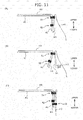
- FIGS. 11A to 11C sewing of this surface material H to the seating portion 20 and the side portions 30 is performed by sewing the large portion H1, the side gusset portion H2, and the hiding cover H3 to one another.
- FIG. 11 illustrating how to sew a portion which corresponds to a cross-section taken along the line a-a in Fig. 1
- first, three sheets of the large portion H1, the side gusset portion H2, and the hiding cover H3 are sewn together via a first sewing portion 51.
- the large portion H1 and the hiding cover H3 are temporarily sewn to each other via a second sewing portion 52.
- FIG. 10 is an explanatory drawing of a fixing surface cover H4.
- This fixing surface cover H4 serves to prevent the hiding material H3 from being unevenly stretched.
- the fixing surface cover H4 is formed as an extended portion integrally formed with the hiding cover H3 to be extended from a center position (center) at an end side of the hiding cover H3 serving as a cover member.
- the fixing surface cover H4 is fixed to the bottom plate 10 by the staples 40.
- the bottom plate 10 of the present embodiment is configured by a single plate body made of resin, for example, polypropylene (PP) or the like. Beads, protruded and recessed portions, or the like for strength improvement are appropriately formed at predetermined portions of the bottom plate 10.
- a rotation mechanism 60 which will be described below is attached to a position on the front of the bottom plate 10 facing the vehicle body.
- a connecting portion 80 (see FIG. 3 ) to be detachably connected to the vehicle body is formed at a position on the rear of the bottom plate 10 facing the vehicle body.
- the connecting portion 80 is a gate-shaped engagement portion and is formed to be engaged and disengaged relative to a catching portion (not shown) or the like which is provided at the vehicle body.
- the side portion 30 corresponding to the lateral portion at the front side of the bottom plate 10 are provided with the cut portions which are formed by cutting out the bottom plate 10 in order to form the recessed portions 70 thereon.
- the cut portion of the present embodiment is a portion cut out into a circular arc shape.
- the cut portion of this circular arc shape forms the recessed portion 70.
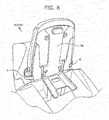
- FIG. 8 is an explanatory drawing illustrating the back side in a condition where a cover 90 for the two or three-wheeled vehicle straddle-type seat S is attached to the seat arranged in a tip-up state.
- FIG. 9 is an explanatory drawing illustrating the back side in a condition where the cover 90 of FIG. 8 is detached from the seat.
- the rotation mechanism is not illustrated in detail.
- the two or three-wheeled vehicle straddle-type seat S as the vehicle seat can be shifted between a seated state and the tip-up state by the rotation mechanism 60.
- the recessed portions 70 for the rotation mechanism 60 are formed at the side portion 30 at the front side facing the rotation mechanism 60.
- this recessed portion 70 is the cut portion which is formed by cutting out the bottom plate 10 and along which the side gusset portion H2 is arranged to cover the cut portion.
- the cut portion serving as the recessed portion 70 has a circular arc shape
- a surface material attachment operation at the time of attachment of the surface material (the side gusset portion H2) along the cut portion can be easily performed with few wrinkles compared with a case where the cut portion has a rectangular shape.
- the outside of the recessed portion is covered by the hiding cover H3 serving as the cover member. Accordingly, even when the side portion 30 at the front side, which is to be in the seated state is exposed to the outside, the recessed portion is not exposed to the outside; therefore, the outer appearance may be improved.
Landscapes
- Engineering & Computer Science (AREA)
- Mechanical Engineering (AREA)
- Aviation & Aerospace Engineering (AREA)
- Transportation (AREA)
- Seats For Vehicles (AREA)
Description
- This invention relates to a vehicle seat, and particularly to a vehicle seat being suitable as a straddle-type seat for a two or three-wheeled vehicle, which has a rear portion movable to shift between a tip-up state and a seated state.
- There has been conventionally known a technique in which a vehicle seat can be shifted between a seated state and a tip-up state by a rotation mechanism such as a hinge mechanism (Patent Document 1). Further rotatable vehicle seats for motorcycles are disclosed in
EP 2 431 264 A1 ,US 2004/222679 A1 andJP H01 202587 A -
EP 2 431 264 A1 discloses a vehicle seat with the features of the preamble ofclaim 1. - PATENT DOCUMENT 1:
JP 2005-262993A - The present invention provides a vehicle seat having the features defined in
claim 1. Further preferred embodiments are defined in the dependent claims. - The rotation mechanism of the vehicle seat may interfere with the seat, for example, a side portion or the like which is an outer periphery of the seat, depending on the shape or size of the rotation mechanism. In addition, "a side portion" in this Description corresponds to an outer periphery of a seat from which a seating portion is excluded, and the side portion is used as an expression including lateral portions at the front and rear sides and lateral portions at the right and left sides.
- A seat for a two or three-wheeled vehicle in which a rotation mechanism may not interfere with a side portion or the like even when the rotation mechanism, for example, its shape or size is changed has been desired.
- It is an object of the present invention to provide a vehicle seat which can be shifted between a tip-up state and a seated state by a rotation mechanism and which is suitable as a straddle-type seat for a two or three-wheeled vehicle in which interference between the rotation mechanism and the seat may not occur.
- The aforementioned problem is solved by a vehicle seat of the present invention, the vehicle seat including a bottom plate, a seating portion, and a side portion, wherein the vehicle seat being configured to be shifted between a seated state and a tip-up state by a rotation mechanism, wherein the seating portion and the side portion are covered by a surface material, and wherein a recessed portion for the rotation mechanism is formed at the side portion facing the rotation mechanism.
- As just described, the recessed portion is formed; therefore, interference between the side portion and the rotation mechanism is inhibited by this recessed portion and the seat can be prevented from increasing in size.
- According to the invention, the recessed portion is a cut portion formed by cutting out the bottom plate.
- As just described, the recessed portion is formed by the cut portion that is formed only by cutting out the bottom plate; therefore, the recessed portion can be easily configured.
- Further, it is more preferable that the recessed portion is a cut portion cut out into a circular arc shape.
- As just described, the cut portion is formed into the circular arc shape; therefore, a reduction of rigidity of the side portion, i.e., an outer periphery of the seat can be prevented.
- According to the invention, the outside of the recessed portion is covered by a cover member.
- As just described, the recessed portion is covered by the cover member; thereby, the entrance of foreign substances via the recessed portion can be prevented.
- According to the invention, the surface material is attached along the cut portion.
- As just described, the cut portion has the circular arc shape. Accordingly, a surface material attachment operation at the time of attachment of the surface material along the cut portion can be easily performed with few wrinkles compared with a case where the cut portion has a rectangular shape.
- Moreover, it is preferable that an extended portion is provided at the cover member and that the extended portion is attached to an inner surface of the side portion.
- As just described, the extended portion is attached to the inner surface of the side portion; thereby, the cover member can be stably attached.
- According to the present invention, interference between the side portion and the rotation mechanism is inhibited by the recessed portion, and in addition, the seat can be prevented from increasing in size. Further, the recessed portion is formed by the cut portion that is formed only by cutting out the bottom plate; therefore, the recessed portion can be easily configured.
- Furthermore, the cut portion has the circular arc shape; thereby, a reduction of rigidity of the side portion, i.e., an outer periphery of the seat can be prevented. The recessed portion is covered by the cover member; thereby, the entrance of foreign substances via the recessed portion can be prevented.
- The cut portion has the circular arc shape. Accordingly, a surface material attachment operation at the time of attachment of the surface material along the cut portion can be easily performed with few wrinkles compared with a case where the cut portion has a rectangular shape. In addition, the extended portion is attached to the inner surface of the side portion; thereby, the cover member can be stably attached.
-
-
FIG. 1 is a perspective view of a two or three-wheeled vehicle straddle-type seat; -
FIG. 2 illustrates a side portion at the lateral side of the two or three-wheeled vehicle straddle-type seat; -
FIG. 3 is a back view of the two or three-wheeled vehicle straddle-type seat; -
FIG. 4 illustrates a side portion at the front side of the two or three-wheeled vehicle straddle-type seat; -
FIG. 5 is an explanatory drawing illustrating an enlarged view of a portion ofFIG. 3 ; -
FIG. 6 is a perspective view illustrating a condition where the seat is arranged in a seated state; -
FIG. 7 is a perspective view illustrating a condition where the seat is arranged in a tip-up state; -
FIG. 8 is an explanatory drawing illustrating the back side in a condition where a cover is attached to the two or three-wheeled vehicle straddle-type seat arranged in the tip-up state; -
FIG. 9 is an explanatory drawing illustrating the back side in a condition where the cover is detached from the two or three-wheeled vehicle straddle-type seat arranged in the tip-up state; -
FIG. 10 is an explanatory drawing of a fixing surface cover; and -
FIG. 11 is an explanatory drawing of a sewn state of a surface material. - Herein, an embodiment of the present invention will be described on the basis of the drawings. In addition, members, arrangements, or the like described below do not restrict the present invention and various modifications or changes may be made within the scope of the present invention.
- A two or three-wheeled vehicle straddle-type seat will be explained as an example of a vehicle seat in the present embodiment. A two or three-wheeled vehicle straddle-type seat S of the present embodiment includes a
bottom plate 10, aseating portion 20, and aside portion 30. In addition, as described above, "theside portion 30" in this Description corresponds to an outer periphery of the seat from which theseating portion 20 is excluded, and the side portion is used as an expression including lateral portions at the front and rear sides and lateral portions at the right and left sides. Moreover, as shown in the drawings, a seat for a front seat and a belt are respectively indicated by symbol Sf and symbol B in the present embodiment. - Further, the two or three-wheeled vehicle straddle-type seat S is configured so that a cushion K mounted on the
bottom plate 10 is covered by a surface material H. More specifically, the cushion K is covered by the surface material H so that theside portions 30 of thebottom plate 10 are wrapped inside the surface material H in a state where end portions of the surface material H are tacked and attached withstaples 40 by using an attachment device such as a tacker to be positioned on the outer periphery of the back side of the bottom plate 10 (a surface thereof facing a vehicle body). Thus, the upper surface side corresponds to theseating portion 20 and the lateral portions of thisseating portion 20 are formed as theside portions 30. - The surface material H is configured by a large portion H1, side gusset portions H2, and a hiding cover H3 for preventing the inside from being seen from the outside. The large portion H1 is configured by forming wooly nylon which is preliminarily formed into a predetermined shape to conform to the seat shape of the two or three-wheeled vehicle straddle-type seat S. The side gusset portion H2 is configured by non-forming wooly nylon which is not formed. The hiding cover H3 is configured by non-forming wooly nylon which is not formed. In the present embodiment as just described, the large portion H1, the side gusset portion H2, and the hiding cover H3 are formed by the same material; therefore, the surface material H can secure uniformity. In addition, the hiding cover H3 covers the outside of a cut portion which is a
recessed portion 70 to be described below; thereby, the outer appearance is improved. - In the present embodiment, the same thickness is applied to the large portion H1 and the side gusset portion H2 of the surface material H while a thickness smaller than the thickness of the large portion H1 and the side gusset portion H2 is applied to the hiding cover H3.
- As shown in
FIG. 1 , the hiding cover H3 in the present embodiment is positioned at the front of theseating portion 20 to be sewn via asewing line 50 to the large portion H1 that covers theseating portion 20, thereby covering theside portion 30 as the lateral portion at the front side. In addition, thissewing line 50 is provided with the belt B described above, thereby being configured to be covered by the belt B and hidden from the outside. Along with the fact that the large portion H1, the side gusset portion H2, and the hiding cover H3 are formed by the same material, the surface material H secures the uniformity. - As shown in
FIGS. 11A to 11C , sewing of this surface material H to theseating portion 20 and theside portions 30 is performed by sewing the large portion H1, the side gusset portion H2, and the hiding cover H3 to one another. In other words, as shown inFIG. 11 illustrating how to sew a portion which corresponds to a cross-section taken along the line a-a inFig. 1 , first, three sheets of the large portion H1, the side gusset portion H2, and the hiding cover H3 are sewn together via afirst sewing portion 51. Next, the large portion H1 and the hiding cover H3 are temporarily sewn to each other via asecond sewing portion 52. Then, a portion (cutting portion 54) of the side gusset portion H2, which is located adjacent to the hiding cover H3 and below thefirst sewing portion 51, is cut off. Thereafter, the three sheets of the large portion H1, the side gusset portion H2, and the hiding cover H3 are simultaneously sewn together by single stitching. - If a portion of the side gusset portion H2, i.e., the cutting
portion 54 is cut off as described above four sheets of the surface material may be typically sewn together via athird sewing portion 53 by single stitching. As a result, unevenness may tend to be generated on the outer appearance. However, as in the present embodiment, after the large portion H1, the side gusset portion H2, and the hiding cover H3 are sewn together via thefirst sewing portion 51, a single seam allowance (the cutting portion 54) of the side gusset portion H2 is cut off. As a result, the unevenness may not be generated on the outer appearance when the large portion H1, the side gusset portion H2, and the hiding cover H3 are sewn together via thethird sewing portion 53; therefore, the outer appearance may have no influence. -
FIG. 10 is an explanatory drawing of a fixing surface cover H4. This fixing surface cover H4 serves to prevent the hiding material H3 from being unevenly stretched. The fixing surface cover H4 is formed as an extended portion integrally formed with the hiding cover H3 to be extended from a center position (center) at an end side of the hiding cover H3 serving as a cover member. In addition, the fixing surface cover H4 is fixed to thebottom plate 10 by thestaples 40. - The
bottom plate 10 of the present embodiment is configured by a single plate body made of resin, for example, polypropylene (PP) or the like. Beads, protruded and recessed portions, or the like for strength improvement are appropriately formed at predetermined portions of thebottom plate 10. Arotation mechanism 60 which will be described below is attached to a position on the front of thebottom plate 10 facing the vehicle body. A connecting portion 80 (seeFIG. 3 ) to be detachably connected to the vehicle body is formed at a position on the rear of thebottom plate 10 facing the vehicle body. The connectingportion 80 is a gate-shaped engagement portion and is formed to be engaged and disengaged relative to a catching portion (not shown) or the like which is provided at the vehicle body. - In addition, the
side portion 30 corresponding to the lateral portion at the front side of thebottom plate 10 are provided with the cut portions which are formed by cutting out thebottom plate 10 in order to form the recessedportions 70 thereon. - The cut portion of the present embodiment is a portion cut out into a circular arc shape. The cut portion of this circular arc shape forms the recessed
portion 70. -
FIG. 8 is an explanatory drawing illustrating the back side in a condition where acover 90 for the two or three-wheeled vehicle straddle-type seat S is attached to the seat arranged in a tip-up state.FIG. 9 is an explanatory drawing illustrating the back side in a condition where thecover 90 ofFIG. 8 is detached from the seat. In these drawings, the rotation mechanism is not illustrated in detail. In addition, the two or three-wheeled vehicle straddle-type seat S as the vehicle seat can be shifted between a seated state and the tip-up state by therotation mechanism 60. - Further, the recessed
portions 70 for therotation mechanism 60 are formed at theside portion 30 at the front side facing therotation mechanism 60. As described above, this recessedportion 70 is the cut portion which is formed by cutting out thebottom plate 10 and along which the side gusset portion H2 is arranged to cover the cut portion. In a case where the cut portion serving as the recessedportion 70 has a circular arc shape, a surface material attachment operation at the time of attachment of the surface material (the side gusset portion H2) along the cut portion can be easily performed with few wrinkles compared with a case where the cut portion has a rectangular shape. - Furthermore, the outside of the recessed portion is covered by the hiding cover H3 serving as the cover member. Accordingly, even when the
side portion 30 at the front side, which is to be in the seated state is exposed to the outside, the recessed portion is not exposed to the outside; therefore, the outer appearance may be improved. -
- 10:
- bottom flame
- 20:
- seating portion
- 30:
- side portion
- 40:
- staple
- 50:
- sewing line
- 51:
- first sewing portion
- 52:
- second sewing portion
- 53:
- third sewing portion
- 54:
- cutting portion
- 60:
- rotation mechanism
- 70:
- recessed portion
- 80:
- connecting portion
- 90:
- cover
- K:
- cushion
- H:
- surface material
- H1:
- large portion
- H2:
- side gusset portion
- H3:
- hiding cover (cover member)
- H4:
- fixing surface cover (extended portion)
- Sf:
- front seat
- B:
- belt
- S:
- two or three-wheeled vehicle straddle-type seat
Claims (4)
- A vehicle seat (S) comprising:a bottom plate (10); a seatingportion (20); and side portions
(30),wherein the vehicle seat (S) is configured to be shifted between a seated state and a tip-up state by a rotation mechanism (60), wherein the seating portion (20) and the side portions (30) are covered by a surface material (H), andwherein a recessed portion (70) for the rotation mechanism (60) is formed at the side portion facing the rotation mechanism (60),wherein the recessed portion (70) is a cut portion formed by cutting out the bottom plate (10),characterized in thatthe surface material (H) is configured by a large portion (H1) that covers the seating portion (20), side gusset portions (H2) that cover the side portions (30), and a cover member (H3) that covers an outside of the recessed portion (70),the cut portion is covered by the side gusset portion (H2) of the surface material (H) that is attached along the cut portion, andthe cover member (H3) covers the outside of the recessed portion (70) such that, even when the side portion (30) at which the recessed portion (70) is formed is exposed to the outside, the recessed portion (70) is not exposed to the outside. - The vehicle seat according to claim 1, wherein the recessed portion (70) is a cut portion cut out into a circular arc shape.
- The vehicle seat according to claim 1 or 2, wherein the large portion (H1), the side gusset portions (H2) and the cover member (H3) are formed by the same material.
- The vehicle seat according to any one of claims 1 to 3, wherein an extended portion (H4) is provided at the cover member (H3), and the extended portion (H4) is attached to an inner surface of the side portion (30) at which the recessed portion (70) is formed.
Applications Claiming Priority (2)
| Application Number | Priority Date | Filing Date | Title |
|---|---|---|---|
| JP2014058898A JP6333593B2 (en) | 2014-03-20 | 2014-03-20 | Vehicle seat |
| PCT/JP2015/058520 WO2015141837A1 (en) | 2014-03-20 | 2015-03-20 | Vehicle seat |
Publications (3)
| Publication Number | Publication Date |
|---|---|
| EP3133003A1 EP3133003A1 (en) | 2017-02-22 |
| EP3133003A4 EP3133003A4 (en) | 2018-01-10 |
| EP3133003B1 true EP3133003B1 (en) | 2020-01-29 |
Family
ID=54144798
Family Applications (1)
| Application Number | Title | Priority Date | Filing Date |
|---|---|---|---|
| EP15765630.7A Active EP3133003B1 (en) | 2014-03-20 | 2015-03-20 | Vehicle seat |
Country Status (4)
| Country | Link |
|---|---|
| US (1) | US10214122B2 (en) |
| EP (1) | EP3133003B1 (en) |
| JP (1) | JP6333593B2 (en) |
| WO (1) | WO2015141837A1 (en) |
Families Citing this family (3)
| Publication number | Priority date | Publication date | Assignee | Title |
|---|---|---|---|---|
| US20170341693A1 (en) * | 2016-05-31 | 2017-11-30 | Josef Rzepecki | Pivotable adaptor for a saddle-type seat |
| US11077902B1 (en) * | 2020-02-04 | 2021-08-03 | Polaris Industries Inc. | Seating assembly in multiple configurations in a two-wheeled vehicle |
| US20230174181A1 (en) * | 2021-12-03 | 2023-06-08 | Polaris Industries Inc. | All-terrain vehicle |
Family Cites Families (14)
| Publication number | Priority date | Publication date | Assignee | Title |
|---|---|---|---|---|
| JPH01202587A (en) * | 1988-02-08 | 1989-08-15 | Suzuki Motor Co Ltd | Illuminating device for motorcycle storage room |
| US7147281B2 (en) * | 2003-05-09 | 2006-12-12 | Honda Motor Co., Ltd. | Motorcycle seat structure |
| JP4177181B2 (en) * | 2003-05-09 | 2008-11-05 | 本田技研工業株式会社 | Motorcycle |
| JP4188136B2 (en) * | 2003-05-09 | 2008-11-26 | 本田技研工業株式会社 | Motorcycle seat structure |
| JP4504054B2 (en) * | 2004-03-17 | 2010-07-14 | 本田技研工業株式会社 | Seat structure for two- and three-wheeled vehicles |
| TWI253423B (en) | 2004-03-17 | 2006-04-21 | Honda Motor Co Ltd | Longitudinally slidable seat structure for two- or three-wheeled vehicle |
| US6971714B1 (en) * | 2004-10-14 | 2005-12-06 | Corbin Pacific, Inc. | Motorcycle seat with convertible backrest |
| JP4544471B2 (en) * | 2005-12-08 | 2010-09-15 | 本田技研工業株式会社 | Sheet structure |
| US7681950B2 (en) * | 2007-06-29 | 2010-03-23 | Harley-Davidson Motor Company Group, LLC | Flip-up seat with rear seat storage |
| JP5451060B2 (en) * | 2007-12-25 | 2014-03-26 | テイ・エス テック株式会社 | Two- and three-wheeled vehicle seats and manufacturing method thereof |
| JP5579000B2 (en) * | 2010-09-17 | 2014-08-27 | 本田技研工業株式会社 | Saddle riding vehicle |
| JP5823265B2 (en) * | 2011-11-28 | 2015-11-25 | テイ・エス テック株式会社 | Motorcycle seat |
| JP5889048B2 (en) * | 2012-03-08 | 2016-03-22 | 本田技研工業株式会社 | Motorcycle |
| ITMI20120151U1 (en) * | 2012-04-13 | 2013-10-14 | Piaggio & C Spa | ASSEMBLED BY A SADDLE AND A SADDLE COMPARTMENT FOR MOTORCYCLES |
-
2014
- 2014-03-20 JP JP2014058898A patent/JP6333593B2/en active Active
-
2015
- 2015-03-20 EP EP15765630.7A patent/EP3133003B1/en active Active
- 2015-03-20 WO PCT/JP2015/058520 patent/WO2015141837A1/en not_active Ceased
- 2015-03-20 US US15/127,071 patent/US10214122B2/en active Active
Non-Patent Citations (1)
| Title |
|---|
| None * |
Also Published As
| Publication number | Publication date |
|---|---|
| WO2015141837A1 (en) | 2015-09-24 |
| JP6333593B2 (en) | 2018-05-30 |
| EP3133003A1 (en) | 2017-02-22 |
| JP2015182503A (en) | 2015-10-22 |
| US10214122B2 (en) | 2019-02-26 |
| US20170106774A1 (en) | 2017-04-20 |
| EP3133003A4 (en) | 2018-01-10 |
Similar Documents
| Publication | Publication Date | Title |
|---|---|---|
| JP5375432B2 (en) | Vehicle seat cover structure | |
| JP5799744B2 (en) | Sheet gap structure | |
| US9592750B2 (en) | Child seat lock device | |
| EP3133003B1 (en) | Vehicle seat | |
| US9010856B2 (en) | Automobile bench seat cover | |
| US20160031411A1 (en) | Lift-up buckle device | |
| JP6085676B2 (en) | Vehicle seat including cover | |
| US20150307004A1 (en) | Vehicle seat | |
| JP2017012227A (en) | Trim cover fixture and trim cover, and vehicle seat | |
| JP2010068901A (en) | Fastening structure of seat cover | |
| US9039092B1 (en) | Air bag enabling car seat cover | |
| JP3200484U (en) | Vehicle seat cover | |
| JP2015182503A5 (en) | ||
| CN105579285B (en) | Interior vehicle components with label | |
| JP2017124668A (en) | Trim cover and vehicle seat | |
| JP6379030B2 (en) | Parts mounting structure | |
| JP2012090677A (en) | Seat cover | |
| JP5928798B2 (en) | Vehicle seat | |
| JP3201742U (en) | How to wear a collar | |
| JP2012240625A (en) | Vehicle seat | |
| US10272963B2 (en) | Conveyance seat | |
| JP3187374U (en) | Spare tire cover | |
| JP5870858B2 (en) | Vehicle seat strap device | |
| JP5182263B2 (en) | Material with skin | |
| JP2009028094A (en) | Vehicle seat |
Legal Events
| Date | Code | Title | Description |
|---|---|---|---|
| STAA | Information on the status of an ep patent application or granted ep patent |
Free format text: STATUS: THE INTERNATIONAL PUBLICATION HAS BEEN MADE |
|
| PUAI | Public reference made under article 153(3) epc to a published international application that has entered the european phase |
Free format text: ORIGINAL CODE: 0009012 |
|
| STAA | Information on the status of an ep patent application or granted ep patent |
Free format text: STATUS: REQUEST FOR EXAMINATION WAS MADE |
|
| 17P | Request for examination filed |
Effective date: 20161018 |
|
| AK | Designated contracting states |
Kind code of ref document: A1 Designated state(s): AL AT BE BG CH CY CZ DE DK EE ES FI FR GB GR HR HU IE IS IT LI LT LU LV MC MK MT NL NO PL PT RO RS SE SI SK SM TR |
|
| AX | Request for extension of the european patent |
Extension state: BA ME |
|
| DAV | Request for validation of the european patent (deleted) | ||
| DAX | Request for extension of the european patent (deleted) | ||
| REG | Reference to a national code |
Ref country code: DE Ref legal event code: R079 Ref document number: 602015046055 Country of ref document: DE Free format text: PREVIOUS MAIN CLASS: B62J0001120000 Ipc: B62J0001140000 |
|
| A4 | Supplementary search report drawn up and despatched |
Effective date: 20171213 |
|
| RIC1 | Information provided on ipc code assigned before grant |
Ipc: B62J 1/12 20060101ALI20171206BHEP Ipc: B62J 1/14 20060101AFI20171206BHEP Ipc: B62J 1/18 20060101ALI20171206BHEP Ipc: B60N 2/40 20060101ALI20171206BHEP Ipc: B62J 1/28 20060101ALI20171206BHEP |
|
| STAA | Information on the status of an ep patent application or granted ep patent |
Free format text: STATUS: EXAMINATION IS IN PROGRESS |
|
| 17Q | First examination report despatched |
Effective date: 20190124 |
|
| GRAP | Despatch of communication of intention to grant a patent |
Free format text: ORIGINAL CODE: EPIDOSNIGR1 |
|
| STAA | Information on the status of an ep patent application or granted ep patent |
Free format text: STATUS: GRANT OF PATENT IS INTENDED |
|
| INTG | Intention to grant announced |
Effective date: 20190927 |
|
| GRAS | Grant fee paid |
Free format text: ORIGINAL CODE: EPIDOSNIGR3 |
|
| GRAA | (expected) grant |
Free format text: ORIGINAL CODE: 0009210 |
|
| STAA | Information on the status of an ep patent application or granted ep patent |
Free format text: STATUS: THE PATENT HAS BEEN GRANTED |
|
| AK | Designated contracting states |
Kind code of ref document: B1 Designated state(s): AL AT BE BG CH CY CZ DE DK EE ES FI FR GB GR HR HU IE IS IT LI LT LU LV MC MK MT NL NO PL PT RO RS SE SI SK SM TR |
|
| REG | Reference to a national code |
Ref country code: GB Ref legal event code: FG4D |
|
| REG | Reference to a national code |
Ref country code: CH Ref legal event code: EP |
|
| REG | Reference to a national code |
Ref country code: AT Ref legal event code: REF Ref document number: 1228319 Country of ref document: AT Kind code of ref document: T Effective date: 20200215 |
|
| REG | Reference to a national code |
Ref country code: IE Ref legal event code: FG4D |
|
| REG | Reference to a national code |
Ref country code: DE Ref legal event code: R096 Ref document number: 602015046055 Country of ref document: DE |
|
| REG | Reference to a national code |
Ref country code: NL Ref legal event code: MP Effective date: 20200129 |
|
| PG25 | Lapsed in a contracting state [announced via postgrant information from national office to epo] |
Ref country code: FI Free format text: LAPSE BECAUSE OF FAILURE TO SUBMIT A TRANSLATION OF THE DESCRIPTION OR TO PAY THE FEE WITHIN THE PRESCRIBED TIME-LIMIT Effective date: 20200129 Ref country code: NO Free format text: LAPSE BECAUSE OF FAILURE TO SUBMIT A TRANSLATION OF THE DESCRIPTION OR TO PAY THE FEE WITHIN THE PRESCRIBED TIME-LIMIT Effective date: 20200429 Ref country code: PT Free format text: LAPSE BECAUSE OF FAILURE TO SUBMIT A TRANSLATION OF THE DESCRIPTION OR TO PAY THE FEE WITHIN THE PRESCRIBED TIME-LIMIT Effective date: 20200621 Ref country code: RS Free format text: LAPSE BECAUSE OF FAILURE TO SUBMIT A TRANSLATION OF THE DESCRIPTION OR TO PAY THE FEE WITHIN THE PRESCRIBED TIME-LIMIT Effective date: 20200129 |
|
| REG | Reference to a national code |
Ref country code: LT Ref legal event code: MG4D |
|
| PG25 | Lapsed in a contracting state [announced via postgrant information from national office to epo] |
Ref country code: BG Free format text: LAPSE BECAUSE OF FAILURE TO SUBMIT A TRANSLATION OF THE DESCRIPTION OR TO PAY THE FEE WITHIN THE PRESCRIBED TIME-LIMIT Effective date: 20200429 Ref country code: HR Free format text: LAPSE BECAUSE OF FAILURE TO SUBMIT A TRANSLATION OF THE DESCRIPTION OR TO PAY THE FEE WITHIN THE PRESCRIBED TIME-LIMIT Effective date: 20200129 Ref country code: IS Free format text: LAPSE BECAUSE OF FAILURE TO SUBMIT A TRANSLATION OF THE DESCRIPTION OR TO PAY THE FEE WITHIN THE PRESCRIBED TIME-LIMIT Effective date: 20200529 Ref country code: LV Free format text: LAPSE BECAUSE OF FAILURE TO SUBMIT A TRANSLATION OF THE DESCRIPTION OR TO PAY THE FEE WITHIN THE PRESCRIBED TIME-LIMIT Effective date: 20200129 Ref country code: SE Free format text: LAPSE BECAUSE OF FAILURE TO SUBMIT A TRANSLATION OF THE DESCRIPTION OR TO PAY THE FEE WITHIN THE PRESCRIBED TIME-LIMIT Effective date: 20200129 Ref country code: GR Free format text: LAPSE BECAUSE OF FAILURE TO SUBMIT A TRANSLATION OF THE DESCRIPTION OR TO PAY THE FEE WITHIN THE PRESCRIBED TIME-LIMIT Effective date: 20200430 |
|
| PG25 | Lapsed in a contracting state [announced via postgrant information from national office to epo] |
Ref country code: NL Free format text: LAPSE BECAUSE OF FAILURE TO SUBMIT A TRANSLATION OF THE DESCRIPTION OR TO PAY THE FEE WITHIN THE PRESCRIBED TIME-LIMIT Effective date: 20200129 |
|
| PG25 | Lapsed in a contracting state [announced via postgrant information from national office to epo] |
Ref country code: MC Free format text: LAPSE BECAUSE OF FAILURE TO SUBMIT A TRANSLATION OF THE DESCRIPTION OR TO PAY THE FEE WITHIN THE PRESCRIBED TIME-LIMIT Effective date: 20200129 Ref country code: ES Free format text: LAPSE BECAUSE OF FAILURE TO SUBMIT A TRANSLATION OF THE DESCRIPTION OR TO PAY THE FEE WITHIN THE PRESCRIBED TIME-LIMIT Effective date: 20200129 Ref country code: CZ Free format text: LAPSE BECAUSE OF FAILURE TO SUBMIT A TRANSLATION OF THE DESCRIPTION OR TO PAY THE FEE WITHIN THE PRESCRIBED TIME-LIMIT Effective date: 20200129 Ref country code: SK Free format text: LAPSE BECAUSE OF FAILURE TO SUBMIT A TRANSLATION OF THE DESCRIPTION OR TO PAY THE FEE WITHIN THE PRESCRIBED TIME-LIMIT Effective date: 20200129 Ref country code: SM Free format text: LAPSE BECAUSE OF FAILURE TO SUBMIT A TRANSLATION OF THE DESCRIPTION OR TO PAY THE FEE WITHIN THE PRESCRIBED TIME-LIMIT Effective date: 20200129 Ref country code: LT Free format text: LAPSE BECAUSE OF FAILURE TO SUBMIT A TRANSLATION OF THE DESCRIPTION OR TO PAY THE FEE WITHIN THE PRESCRIBED TIME-LIMIT Effective date: 20200129 Ref country code: RO Free format text: LAPSE BECAUSE OF FAILURE TO SUBMIT A TRANSLATION OF THE DESCRIPTION OR TO PAY THE FEE WITHIN THE PRESCRIBED TIME-LIMIT Effective date: 20200129 Ref country code: DK Free format text: LAPSE BECAUSE OF FAILURE TO SUBMIT A TRANSLATION OF THE DESCRIPTION OR TO PAY THE FEE WITHIN THE PRESCRIBED TIME-LIMIT Effective date: 20200129 Ref country code: EE Free format text: LAPSE BECAUSE OF FAILURE TO SUBMIT A TRANSLATION OF THE DESCRIPTION OR TO PAY THE FEE WITHIN THE PRESCRIBED TIME-LIMIT Effective date: 20200129 |
|
| REG | Reference to a national code |
Ref country code: CH Ref legal event code: PL Ref country code: DE Ref legal event code: R097 Ref document number: 602015046055 Country of ref document: DE |
|
| REG | Reference to a national code |
Ref country code: AT Ref legal event code: MK05 Ref document number: 1228319 Country of ref document: AT Kind code of ref document: T Effective date: 20200129 |
|
| PLBE | No opposition filed within time limit |
Free format text: ORIGINAL CODE: 0009261 |
|
| STAA | Information on the status of an ep patent application or granted ep patent |
Free format text: STATUS: NO OPPOSITION FILED WITHIN TIME LIMIT |
|
| REG | Reference to a national code |
Ref country code: BE Ref legal event code: MM Effective date: 20200331 |
|
| PG25 | Lapsed in a contracting state [announced via postgrant information from national office to epo] |
Ref country code: LU Free format text: LAPSE BECAUSE OF NON-PAYMENT OF DUE FEES Effective date: 20200320 |
|
| 26N | No opposition filed |
Effective date: 20201030 |
|
| PG25 | Lapsed in a contracting state [announced via postgrant information from national office to epo] |
Ref country code: LI Free format text: LAPSE BECAUSE OF NON-PAYMENT OF DUE FEES Effective date: 20200331 Ref country code: IE Free format text: LAPSE BECAUSE OF NON-PAYMENT OF DUE FEES Effective date: 20200320 Ref country code: FR Free format text: LAPSE BECAUSE OF NON-PAYMENT OF DUE FEES Effective date: 20200329 Ref country code: AT Free format text: LAPSE BECAUSE OF FAILURE TO SUBMIT A TRANSLATION OF THE DESCRIPTION OR TO PAY THE FEE WITHIN THE PRESCRIBED TIME-LIMIT Effective date: 20200129 Ref country code: CH Free format text: LAPSE BECAUSE OF NON-PAYMENT OF DUE FEES Effective date: 20200331 Ref country code: IT Free format text: LAPSE BECAUSE OF FAILURE TO SUBMIT A TRANSLATION OF THE DESCRIPTION OR TO PAY THE FEE WITHIN THE PRESCRIBED TIME-LIMIT Effective date: 20200129 |
|
| PG25 | Lapsed in a contracting state [announced via postgrant information from national office to epo] |
Ref country code: PL Free format text: LAPSE BECAUSE OF FAILURE TO SUBMIT A TRANSLATION OF THE DESCRIPTION OR TO PAY THE FEE WITHIN THE PRESCRIBED TIME-LIMIT Effective date: 20200129 Ref country code: BE Free format text: LAPSE BECAUSE OF NON-PAYMENT OF DUE FEES Effective date: 20200331 Ref country code: SI Free format text: LAPSE BECAUSE OF FAILURE TO SUBMIT A TRANSLATION OF THE DESCRIPTION OR TO PAY THE FEE WITHIN THE PRESCRIBED TIME-LIMIT Effective date: 20200129 |
|
| GBPC | Gb: european patent ceased through non-payment of renewal fee |
Effective date: 20200429 |
|
| PG25 | Lapsed in a contracting state [announced via postgrant information from national office to epo] |
Ref country code: GB Free format text: LAPSE BECAUSE OF NON-PAYMENT OF DUE FEES Effective date: 20200429 |
|
| PG25 | Lapsed in a contracting state [announced via postgrant information from national office to epo] |
Ref country code: TR Free format text: LAPSE BECAUSE OF FAILURE TO SUBMIT A TRANSLATION OF THE DESCRIPTION OR TO PAY THE FEE WITHIN THE PRESCRIBED TIME-LIMIT Effective date: 20200129 Ref country code: MT Free format text: LAPSE BECAUSE OF FAILURE TO SUBMIT A TRANSLATION OF THE DESCRIPTION OR TO PAY THE FEE WITHIN THE PRESCRIBED TIME-LIMIT Effective date: 20200129 Ref country code: CY Free format text: LAPSE BECAUSE OF FAILURE TO SUBMIT A TRANSLATION OF THE DESCRIPTION OR TO PAY THE FEE WITHIN THE PRESCRIBED TIME-LIMIT Effective date: 20200129 |
|
| PG25 | Lapsed in a contracting state [announced via postgrant information from national office to epo] |
Ref country code: MK Free format text: LAPSE BECAUSE OF FAILURE TO SUBMIT A TRANSLATION OF THE DESCRIPTION OR TO PAY THE FEE WITHIN THE PRESCRIBED TIME-LIMIT Effective date: 20200129 Ref country code: AL Free format text: LAPSE BECAUSE OF FAILURE TO SUBMIT A TRANSLATION OF THE DESCRIPTION OR TO PAY THE FEE WITHIN THE PRESCRIBED TIME-LIMIT Effective date: 20200129 |
|
| PGFP | Annual fee paid to national office [announced via postgrant information from national office to epo] |
Ref country code: DE Payment date: 20260319 Year of fee payment: 12 |