EP3132961A2 - Power unit for a hybrid electric vehicle - Google Patents
Power unit for a hybrid electric vehicle Download PDFInfo
- Publication number
- EP3132961A2 EP3132961A2 EP16181617.8A EP16181617A EP3132961A2 EP 3132961 A2 EP3132961 A2 EP 3132961A2 EP 16181617 A EP16181617 A EP 16181617A EP 3132961 A2 EP3132961 A2 EP 3132961A2
- Authority
- EP
- European Patent Office
- Prior art keywords
- output shaft
- gearbox
- power unit
- axis
- internal combustion
- Prior art date
- Legal status (The legal status is an assumption and is not a legal conclusion. Google has not performed a legal analysis and makes no representation as to the accuracy of the status listed.)
- Withdrawn
Links
- 238000002485 combustion reaction Methods 0.000 claims abstract description 34
- 230000005611 electricity Effects 0.000 description 7
- 238000011068 loading method Methods 0.000 description 6
- 230000008878 coupling Effects 0.000 description 4
- 238000010168 coupling process Methods 0.000 description 4
- 238000005859 coupling reaction Methods 0.000 description 4
- 238000005516 engineering process Methods 0.000 description 4
- 230000001172 regenerating effect Effects 0.000 description 3
- 239000013589 supplement Substances 0.000 description 3
- 239000002184 metal Substances 0.000 description 2
- 239000003921 oil Substances 0.000 description 2
- 239000007858 starting material Substances 0.000 description 2
- OKTJSMMVPCPJKN-UHFFFAOYSA-N Carbon Chemical compound [C] OKTJSMMVPCPJKN-UHFFFAOYSA-N 0.000 description 1
- 238000004378 air conditioning Methods 0.000 description 1
- 229910052799 carbon Inorganic materials 0.000 description 1
- 238000005266 casting Methods 0.000 description 1
- 230000010485 coping Effects 0.000 description 1
- 239000012530 fluid Substances 0.000 description 1
- 239000000446 fuel Substances 0.000 description 1
- 230000004048 modification Effects 0.000 description 1
- 238000012986 modification Methods 0.000 description 1
- 239000010705 motor oil Substances 0.000 description 1
- 230000001502 supplementing effect Effects 0.000 description 1
Images

Classifications
-
- B—PERFORMING OPERATIONS; TRANSPORTING
- B60—VEHICLES IN GENERAL
- B60K—ARRANGEMENT OR MOUNTING OF PROPULSION UNITS OR OF TRANSMISSIONS IN VEHICLES; ARRANGEMENT OR MOUNTING OF PLURAL DIVERSE PRIME-MOVERS IN VEHICLES; AUXILIARY DRIVES FOR VEHICLES; INSTRUMENTATION OR DASHBOARDS FOR VEHICLES; ARRANGEMENTS IN CONNECTION WITH COOLING, AIR INTAKE, GAS EXHAUST OR FUEL SUPPLY OF PROPULSION UNITS IN VEHICLES
- B60K6/00—Arrangement or mounting of plural diverse prime-movers for mutual or common propulsion, e.g. hybrid propulsion systems comprising electric motors and internal combustion engines ; Control systems therefor, i.e. systems controlling two or more prime movers, or controlling one of these prime movers and any of the transmission, drive or drive units Informative references: mechanical gearings with secondary electric drive F16H3/72; arrangements for handling mechanical energy structurally associated with the dynamo-electric machine H02K7/00; machines comprising structurally interrelated motor and generator parts H02K51/00; dynamo-electric machines not otherwise provided for in H02K see H02K99/00
- B60K6/20—Arrangement or mounting of plural diverse prime-movers for mutual or common propulsion, e.g. hybrid propulsion systems comprising electric motors and internal combustion engines ; Control systems therefor, i.e. systems controlling two or more prime movers, or controlling one of these prime movers and any of the transmission, drive or drive units Informative references: mechanical gearings with secondary electric drive F16H3/72; arrangements for handling mechanical energy structurally associated with the dynamo-electric machine H02K7/00; machines comprising structurally interrelated motor and generator parts H02K51/00; dynamo-electric machines not otherwise provided for in H02K see H02K99/00 the prime-movers consisting of electric motors and internal combustion engines, e.g. HEVs
- B60K6/42—Arrangement or mounting of plural diverse prime-movers for mutual or common propulsion, e.g. hybrid propulsion systems comprising electric motors and internal combustion engines ; Control systems therefor, i.e. systems controlling two or more prime movers, or controlling one of these prime movers and any of the transmission, drive or drive units Informative references: mechanical gearings with secondary electric drive F16H3/72; arrangements for handling mechanical energy structurally associated with the dynamo-electric machine H02K7/00; machines comprising structurally interrelated motor and generator parts H02K51/00; dynamo-electric machines not otherwise provided for in H02K see H02K99/00 the prime-movers consisting of electric motors and internal combustion engines, e.g. HEVs characterised by the architecture of the hybrid electric vehicle
- B60K6/48—Parallel type
-
- B—PERFORMING OPERATIONS; TRANSPORTING
- B60—VEHICLES IN GENERAL
- B60K—ARRANGEMENT OR MOUNTING OF PROPULSION UNITS OR OF TRANSMISSIONS IN VEHICLES; ARRANGEMENT OR MOUNTING OF PLURAL DIVERSE PRIME-MOVERS IN VEHICLES; AUXILIARY DRIVES FOR VEHICLES; INSTRUMENTATION OR DASHBOARDS FOR VEHICLES; ARRANGEMENTS IN CONNECTION WITH COOLING, AIR INTAKE, GAS EXHAUST OR FUEL SUPPLY OF PROPULSION UNITS IN VEHICLES
- B60K1/00—Arrangement or mounting of electrical propulsion units
- B60K1/02—Arrangement or mounting of electrical propulsion units comprising more than one electric motor
-
- F—MECHANICAL ENGINEERING; LIGHTING; HEATING; WEAPONS; BLASTING
- F16—ENGINEERING ELEMENTS AND UNITS; GENERAL MEASURES FOR PRODUCING AND MAINTAINING EFFECTIVE FUNCTIONING OF MACHINES OR INSTALLATIONS; THERMAL INSULATION IN GENERAL
- F16H—GEARING
- F16H7/00—Gearings for conveying rotary motion by endless flexible members
- F16H7/02—Gearings for conveying rotary motion by endless flexible members with belts; with V-belts
-
- B—PERFORMING OPERATIONS; TRANSPORTING
- B60—VEHICLES IN GENERAL
- B60K—ARRANGEMENT OR MOUNTING OF PROPULSION UNITS OR OF TRANSMISSIONS IN VEHICLES; ARRANGEMENT OR MOUNTING OF PLURAL DIVERSE PRIME-MOVERS IN VEHICLES; AUXILIARY DRIVES FOR VEHICLES; INSTRUMENTATION OR DASHBOARDS FOR VEHICLES; ARRANGEMENTS IN CONNECTION WITH COOLING, AIR INTAKE, GAS EXHAUST OR FUEL SUPPLY OF PROPULSION UNITS IN VEHICLES
- B60K25/00—Auxiliary drives
- B60K25/06—Auxiliary drives from the transmission power take-off
-
- B—PERFORMING OPERATIONS; TRANSPORTING
- B60—VEHICLES IN GENERAL
- B60K—ARRANGEMENT OR MOUNTING OF PROPULSION UNITS OR OF TRANSMISSIONS IN VEHICLES; ARRANGEMENT OR MOUNTING OF PLURAL DIVERSE PRIME-MOVERS IN VEHICLES; AUXILIARY DRIVES FOR VEHICLES; INSTRUMENTATION OR DASHBOARDS FOR VEHICLES; ARRANGEMENTS IN CONNECTION WITH COOLING, AIR INTAKE, GAS EXHAUST OR FUEL SUPPLY OF PROPULSION UNITS IN VEHICLES
- B60K6/00—Arrangement or mounting of plural diverse prime-movers for mutual or common propulsion, e.g. hybrid propulsion systems comprising electric motors and internal combustion engines ; Control systems therefor, i.e. systems controlling two or more prime movers, or controlling one of these prime movers and any of the transmission, drive or drive units Informative references: mechanical gearings with secondary electric drive F16H3/72; arrangements for handling mechanical energy structurally associated with the dynamo-electric machine H02K7/00; machines comprising structurally interrelated motor and generator parts H02K51/00; dynamo-electric machines not otherwise provided for in H02K see H02K99/00
- B60K6/20—Arrangement or mounting of plural diverse prime-movers for mutual or common propulsion, e.g. hybrid propulsion systems comprising electric motors and internal combustion engines ; Control systems therefor, i.e. systems controlling two or more prime movers, or controlling one of these prime movers and any of the transmission, drive or drive units Informative references: mechanical gearings with secondary electric drive F16H3/72; arrangements for handling mechanical energy structurally associated with the dynamo-electric machine H02K7/00; machines comprising structurally interrelated motor and generator parts H02K51/00; dynamo-electric machines not otherwise provided for in H02K see H02K99/00 the prime-movers consisting of electric motors and internal combustion engines, e.g. HEVs
- B60K6/22—Arrangement or mounting of plural diverse prime-movers for mutual or common propulsion, e.g. hybrid propulsion systems comprising electric motors and internal combustion engines ; Control systems therefor, i.e. systems controlling two or more prime movers, or controlling one of these prime movers and any of the transmission, drive or drive units Informative references: mechanical gearings with secondary electric drive F16H3/72; arrangements for handling mechanical energy structurally associated with the dynamo-electric machine H02K7/00; machines comprising structurally interrelated motor and generator parts H02K51/00; dynamo-electric machines not otherwise provided for in H02K see H02K99/00 the prime-movers consisting of electric motors and internal combustion engines, e.g. HEVs characterised by apparatus, components or means specially adapted for HEVs
- B60K6/40—Arrangement or mounting of plural diverse prime-movers for mutual or common propulsion, e.g. hybrid propulsion systems comprising electric motors and internal combustion engines ; Control systems therefor, i.e. systems controlling two or more prime movers, or controlling one of these prime movers and any of the transmission, drive or drive units Informative references: mechanical gearings with secondary electric drive F16H3/72; arrangements for handling mechanical energy structurally associated with the dynamo-electric machine H02K7/00; machines comprising structurally interrelated motor and generator parts H02K51/00; dynamo-electric machines not otherwise provided for in H02K see H02K99/00 the prime-movers consisting of electric motors and internal combustion engines, e.g. HEVs characterised by apparatus, components or means specially adapted for HEVs characterised by the assembly or relative disposition of components
-
- F—MECHANICAL ENGINEERING; LIGHTING; HEATING; WEAPONS; BLASTING
- F02—COMBUSTION ENGINES; HOT-GAS OR COMBUSTION-PRODUCT ENGINE PLANTS
- F02B—INTERNAL-COMBUSTION PISTON ENGINES; COMBUSTION ENGINES IN GENERAL
- F02B67/00—Engines characterised by the arrangement of auxiliary apparatus not being otherwise provided for, e.g. the apparatus having different functions; Driving auxiliary apparatus from engines, not otherwise provided for
- F02B67/04—Engines characterised by the arrangement of auxiliary apparatus not being otherwise provided for, e.g. the apparatus having different functions; Driving auxiliary apparatus from engines, not otherwise provided for of mechanically-driven auxiliary apparatus
- F02B67/06—Engines characterised by the arrangement of auxiliary apparatus not being otherwise provided for, e.g. the apparatus having different functions; Driving auxiliary apparatus from engines, not otherwise provided for of mechanically-driven auxiliary apparatus driven by means of chains, belts, or like endless members
-
- B—PERFORMING OPERATIONS; TRANSPORTING
- B60—VEHICLES IN GENERAL
- B60K—ARRANGEMENT OR MOUNTING OF PROPULSION UNITS OR OF TRANSMISSIONS IN VEHICLES; ARRANGEMENT OR MOUNTING OF PLURAL DIVERSE PRIME-MOVERS IN VEHICLES; AUXILIARY DRIVES FOR VEHICLES; INSTRUMENTATION OR DASHBOARDS FOR VEHICLES; ARRANGEMENTS IN CONNECTION WITH COOLING, AIR INTAKE, GAS EXHAUST OR FUEL SUPPLY OF PROPULSION UNITS IN VEHICLES
- B60K6/00—Arrangement or mounting of plural diverse prime-movers for mutual or common propulsion, e.g. hybrid propulsion systems comprising electric motors and internal combustion engines ; Control systems therefor, i.e. systems controlling two or more prime movers, or controlling one of these prime movers and any of the transmission, drive or drive units Informative references: mechanical gearings with secondary electric drive F16H3/72; arrangements for handling mechanical energy structurally associated with the dynamo-electric machine H02K7/00; machines comprising structurally interrelated motor and generator parts H02K51/00; dynamo-electric machines not otherwise provided for in H02K see H02K99/00
- B60K6/20—Arrangement or mounting of plural diverse prime-movers for mutual or common propulsion, e.g. hybrid propulsion systems comprising electric motors and internal combustion engines ; Control systems therefor, i.e. systems controlling two or more prime movers, or controlling one of these prime movers and any of the transmission, drive or drive units Informative references: mechanical gearings with secondary electric drive F16H3/72; arrangements for handling mechanical energy structurally associated with the dynamo-electric machine H02K7/00; machines comprising structurally interrelated motor and generator parts H02K51/00; dynamo-electric machines not otherwise provided for in H02K see H02K99/00 the prime-movers consisting of electric motors and internal combustion engines, e.g. HEVs
- B60K6/42—Arrangement or mounting of plural diverse prime-movers for mutual or common propulsion, e.g. hybrid propulsion systems comprising electric motors and internal combustion engines ; Control systems therefor, i.e. systems controlling two or more prime movers, or controlling one of these prime movers and any of the transmission, drive or drive units Informative references: mechanical gearings with secondary electric drive F16H3/72; arrangements for handling mechanical energy structurally associated with the dynamo-electric machine H02K7/00; machines comprising structurally interrelated motor and generator parts H02K51/00; dynamo-electric machines not otherwise provided for in H02K see H02K99/00 the prime-movers consisting of electric motors and internal combustion engines, e.g. HEVs characterised by the architecture of the hybrid electric vehicle
- B60K6/48—Parallel type
- B60K2006/4808—Electric machine connected or connectable to gearbox output shaft
-
- B—PERFORMING OPERATIONS; TRANSPORTING
- B60—VEHICLES IN GENERAL
- B60K—ARRANGEMENT OR MOUNTING OF PROPULSION UNITS OR OF TRANSMISSIONS IN VEHICLES; ARRANGEMENT OR MOUNTING OF PLURAL DIVERSE PRIME-MOVERS IN VEHICLES; AUXILIARY DRIVES FOR VEHICLES; INSTRUMENTATION OR DASHBOARDS FOR VEHICLES; ARRANGEMENTS IN CONNECTION WITH COOLING, AIR INTAKE, GAS EXHAUST OR FUEL SUPPLY OF PROPULSION UNITS IN VEHICLES
- B60K6/00—Arrangement or mounting of plural diverse prime-movers for mutual or common propulsion, e.g. hybrid propulsion systems comprising electric motors and internal combustion engines ; Control systems therefor, i.e. systems controlling two or more prime movers, or controlling one of these prime movers and any of the transmission, drive or drive units Informative references: mechanical gearings with secondary electric drive F16H3/72; arrangements for handling mechanical energy structurally associated with the dynamo-electric machine H02K7/00; machines comprising structurally interrelated motor and generator parts H02K51/00; dynamo-electric machines not otherwise provided for in H02K see H02K99/00
- B60K6/20—Arrangement or mounting of plural diverse prime-movers for mutual or common propulsion, e.g. hybrid propulsion systems comprising electric motors and internal combustion engines ; Control systems therefor, i.e. systems controlling two or more prime movers, or controlling one of these prime movers and any of the transmission, drive or drive units Informative references: mechanical gearings with secondary electric drive F16H3/72; arrangements for handling mechanical energy structurally associated with the dynamo-electric machine H02K7/00; machines comprising structurally interrelated motor and generator parts H02K51/00; dynamo-electric machines not otherwise provided for in H02K see H02K99/00 the prime-movers consisting of electric motors and internal combustion engines, e.g. HEVs
- B60K6/42—Arrangement or mounting of plural diverse prime-movers for mutual or common propulsion, e.g. hybrid propulsion systems comprising electric motors and internal combustion engines ; Control systems therefor, i.e. systems controlling two or more prime movers, or controlling one of these prime movers and any of the transmission, drive or drive units Informative references: mechanical gearings with secondary electric drive F16H3/72; arrangements for handling mechanical energy structurally associated with the dynamo-electric machine H02K7/00; machines comprising structurally interrelated motor and generator parts H02K51/00; dynamo-electric machines not otherwise provided for in H02K see H02K99/00 the prime-movers consisting of electric motors and internal combustion engines, e.g. HEVs characterised by the architecture of the hybrid electric vehicle
- B60K6/48—Parallel type
- B60K2006/4833—Step up or reduction gearing driving generator, e.g. to operate generator in most efficient speed range
-
- B—PERFORMING OPERATIONS; TRANSPORTING
- B60—VEHICLES IN GENERAL
- B60W—CONJOINT CONTROL OF VEHICLE SUB-UNITS OF DIFFERENT TYPE OR DIFFERENT FUNCTION; CONTROL SYSTEMS SPECIALLY ADAPTED FOR HYBRID VEHICLES; ROAD VEHICLE DRIVE CONTROL SYSTEMS FOR PURPOSES NOT RELATED TO THE CONTROL OF A PARTICULAR SUB-UNIT
- B60W2300/00—Indexing codes relating to the type of vehicle
- B60W2300/10—Buses
-
- Y—GENERAL TAGGING OF NEW TECHNOLOGICAL DEVELOPMENTS; GENERAL TAGGING OF CROSS-SECTIONAL TECHNOLOGIES SPANNING OVER SEVERAL SECTIONS OF THE IPC; TECHNICAL SUBJECTS COVERED BY FORMER USPC CROSS-REFERENCE ART COLLECTIONS [XRACs] AND DIGESTS
- Y02—TECHNOLOGIES OR APPLICATIONS FOR MITIGATION OR ADAPTATION AGAINST CLIMATE CHANGE
- Y02T—CLIMATE CHANGE MITIGATION TECHNOLOGIES RELATED TO TRANSPORTATION
- Y02T10/00—Road transport of goods or passengers
- Y02T10/60—Other road transportation technologies with climate change mitigation effect
- Y02T10/62—Hybrid vehicles
Landscapes
- Engineering & Computer Science (AREA)
- Mechanical Engineering (AREA)
- Chemical & Material Sciences (AREA)
- Combustion & Propulsion (AREA)
- Transportation (AREA)
- General Engineering & Computer Science (AREA)
- Hybrid Electric Vehicles (AREA)
- Arrangement Of Transmissions (AREA)
Abstract
Description
- This invention relates to a power unit for a hybrid electric vehicle, in particular a commercial vehicle, such as a bus.
- Hybrid Electric Vehicles (HEVs) combines a conventional internal combustion engine propulsion system with an electric propulsion system. Typically HEVs use their internal combustion engine to drive an electrical generator, generating electricity to either recharge batteries or to directly power one or more electric drive motors. HEVs typically make use of efficiency-improving technologies such as regenerative brakes, whereby a vehicle's kinetic energy is converted into electric energy by driving an electrical generator, rather than wasting it as heat energy as conventional brakes do. It is also known to reduce vehicle emissions by shutting down the internal combustion engine at idle and restarting it when needed. This is known as a start-stop system. Often the electrical generator is also used as a motor to start and/or drive the internal combustion engine, as a starter motor and/or to supplement the power supplied by the internal combustion engine. This type of generator is typically referred to as a motor generator.
- Particularly in lower voltage systems, such as 48 volt systems, the internal combustion engine drives the drive wheels of the vehicle via a gearbox and a motor generator is used to supplement the power supplied by the internal combustion engine, to start the engine and to generate electricity to charge the batteries, particularly during regenerative braking. This arrangement is often referred to as a "micro-hybrid" vehicle.
- Typically such motor generators are driven from the output shaft of the internal combustion engine via a drive belt running around pulleys on the rotor shaft of the motor generator and on the output shaft of the internal combustion engine, said drive belt also typically driving other ancillary components, such as power steering and air conditioning pumps. This allows the motor generator to spin faster than the output shaft of the internal combustion engine by the use of suitably sized pulleys.
- However, such drive belts can require complex tensioning arrangements required to allow the motor generator to both drive and be driven by the internal combustion engine, whereby the tension on either side of the drive belt varies. Also, such motor generators, particularly where large output devices are used, require considerable belt tension to prevent belt slippage under load. This can place excessive lateral loadings on the output shaft of the engine.
- Typically the crankshaft of an internal combustion engine runs on plain bearings which rely on engine oil pressure to avoid metal on metal contact. Such bearings are extremely intolerant to loadings extending parallel to the join line of the two halves of the bearing, typically arranged in a horizontal plane to the usual vertical alignment of the cylinders of the internal combustion engine. This is a particular problem during engine start up when the oil pressure may be low. However, space requirement typically dictate that the motor generator be laterally spaced to one side of the output shaft of the engine, thus limiting the size of the motor generator that may be used.
- This is not such a problem in small automobiles, with relatively small output petrol engines and correspondingly small output motor generators. However, in commercial vehicles where larger diesel engines are typically used the size requirements of the motor generator and thus the belt tension required to prevent slippage can lead to the imposition of excessive lateral forces on the output shaft of the internal combustion engine.
- An object of the present invention is to provide a power unit for a hybrid electric vehicle, in particular a commercial vehicle such as a bus, that overcomes the abovementioned problem.
- According to the present invention there is provided a power unit for a hybrid electric vehicle comprising an internal combustion engine coupled to a gearbox, the gearbox having an output shaft with an axis of rotation, a first rotary device mounted on a first side of the axis of rotation of the output shaft, a second rotary device mounted on a second side of the axis of rotation of the output shaft, opposite said first side, each of said first and second rotary devices having a respective rotor shaft disposed parallel to the output shaft of the gearbox and being mechanically coupled to said output shaft for transmitting torque between the respective rotor shaft and the output shaft, wherein said first and second rotary devices are arranged substantially symmetrically about a plane aligned with the axis of rotation of the output shaft of the gearbox.
- Preferably the rotor shaft of each of said first and second rotary devices is coupled to the output shaft of said internal combustion engine by a respective endless member. Each endless member may include a respective tensioning device. In a preferred embodiment the rotor shafts of the first and second rotary devices are located in a plane located vertically offset from the axis of rotation of the output shaft of the gearbox, each tensioning device comprising an idler roller or gear acting the respective endless member whereby the upper and lower runs of each endless member extend from the output shaft at the same angle to a horizontal plane passing through the rotational axis of the output shaft, thus balancing the forces applied to the output shaft both laterally and vertically.
- In a preferred embodiment each endless member comprises a belt.
- Said endless members may be axially offset from one another with respect to the rotational axis of the output shaft and are coupled to the output shaft via a common pulley.
- In a preferred embodiment said first and second rotary devices are each located beside the gearbox, said rotary device being located on either side of the gearbox.
- Said first and second rotary devices may be mounted on a common sub-frame coupled to the gearbox to prevent the transfer of loads from the rotary devices to the gearbox housing. Alternatively it is envisaged that the first and second rotary devices may be mounted on a housing of the gearbox.
- At least one of said first and second rotary devices comprises a motor generator. In a preferred embodiment both of said first and second rotary devices comprise motor generators.
- Said internal combustion engine may comprise a diesel engine.
- Said gearbox may comprise an automatic gearbox coupled to the internal combustion engine via a torque converter.
- According to a further aspect of the present invention there is provided a commercial vehicle incorporating a power unit in accordance with the first aspect of the invention. Preferably said vehicle comprises a bus.
- A power unit for a hybrid electric commercial vehicle, in particular a bus, will now be described by way of example only, with reference to the accompanying drawings, in which :-
-
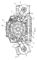
Figure 1 is a perspective view of a power unit for a hybrid electric commercial vehicle in accordance with a first embodiment of the present invention; and -
Figure 2 is an end view of the power unit ofFigure 1 . - As shown in the drawings, a power unit for a hybrid electric commercial vehicle in accordance with an embodiment of the present invention comprises an internal combustion engine, typically a diesel engine, drivingly coupled to a
gearbox 2 via a clutch or a torque converter, anoutput shaft 4 of thegearbox 2 being coupled to drive wheels of the vehicle via a propeller shaft (not shown). - A pair of
motor generators output shaft 4 of thegearbox 2 whereby themotor generators output shaft 4 for generating electricity or may drive theoutput shaft 4 to provide power to the driving wheels of the vehicle. By coupling the motor generators to theoutput shaft 4 of thegearbox 2 rather than to the crankshaft of the engine the transfer of load from themotor generators motor generators - The internal combustion engine may comprise a four cylinder diesel engine of around 4 litre capacity, for example for use in a commercial vehicle, more particularly a lightweight bus, such as the Wrightbus StreetLite 40 seat range. However, other engine configurations and sizes, fuelled by diesel, petrol or Ipg, for numerous other applications, are envisaged.
- The
gearbox 2 will typically be an automatic gearbox coupled to the engine via a torque converter, as commonly used in lightweight buses. However, it is also envisaged that the gearbox may comprise a manual gearbox coupled to the engine via a clutch. - The lightweight bus market is becoming increasingly popular due to flexibility and low running costs compared to a large double deck bus. By incorporating hybrid electric technology, lightweight diesel buses can achieve low carbon emission bus accreditation, often required for city centre use. In what is often referred to as a "micro-hybrid", the internal combustion engine is coupled to a motor generator which charges the batteries during braking to power auxiliaries, delivering a significant fuel saving, while acting as a starter motor for engine starting, facilitating the use of stop start technology, and supplementing the power of the internal combustion engine when required, for example to mitigate turbo lag, without the extra costs associated with a full hybrid vehicle's complexity and batteries (i.e. where electric motors drive the vehicle and the internal combustion engine is used solely to charge batteries).
- However, as discussed above, the use of a single relatively large motor generator coupled to the crankshaft of the internal combustion engine by a belt drive can place an excessive lateral load on the bearings of the crankshaft.
- The power unit in accordance with the present invention solves this problem by utilising two
smaller motor generators motor generators motor generators output shaft 4 of thegearbox 2 of the internal combustion engine. - The
motor generators respective drive belts output shaft 4 of the internal combustion engine by the twomotor generators drive belt respective pulley rotor shaft respective motor generator pulley 18 mounted on theoutput shaft 4 of thegearbox 2. Thedrive belts motor generators drive belts pulley 18. - Polymeric drive belts are preferred because the elasticity of the belts effectively vibrationally isolates the
motor generators gearbox 2. The polymeric drive belts also cope better with the torque reversal caused when the motor generators switch from generating electricity to driving the vehicle. However, it is envisaged that other drive means may be used for transferring drive between the motor generators and the engine, for example chains and sprockets or gearing or hydraulic motors/pumps. - As shown in the drawings, in a preferred embodiment each
motor generator sub-frame 24 coupled to thegearbox 2 such that themotor generators motor generators belts -
Tensioning devices belt idler roller respective belt idler roller sub-frame 24 and therespective idler roller tensioning device belt respective idler roller - In an alternative embodiment (not shown) each
tensioning device motor generators - In a further embodiment (not shown) the tensioning devices may be mechanically linked to equalise the tension applied to each belt. By coupling the two
motor generators drive belts output shaft 4 of thegearbox 2. - In the embodiment shown in the drawings, the rotor shafts of the
motor generators output shaft 4 of thegearbox 2 in order to minimise the height of the assembly. This would normally have the disadvantage of placing a resultant radial loading on the output shaft in a downwards direction. In order to avoid this, theidler roller tensioning device belt pulley 18 at the same angle to the horizontal, in directions aligned with a respective common point on a horizontal axis passing through the rotational axis of theoutput shaft 4. Theidler rollers output shaft 4. - Alternatively, it is envisaged that the rotor shafts of the
motor generators output shaft 4 of thegearbox 2 in a substantially horizontal plane. - While the invention has been described in relation to the use of paired motor generators, it is envisaged that other rotary machine may be provided in place of one or both of the motor generators, for example hydraulic machines, such as fluid pumps and/or hydraulic motors.
- By coupling the
motor generators gearbox 2 in this way, on either side of the gearbox usingdrive belts motor generators output shaft 4 of theinternal combustion engine 2 and thus enabling the implementation of hybrid electric vehicle technology without substantial modification to the internal combustion engine or the vehicle. - The invention is not limited to the embodiment(s) described herein but can be amended or modified without departing from the scope of the present invention.
Claims (15)
- A power unit for a hybrid electric vehicle comprising an internal combustion engine coupled to a gearbox, the gearbox having an output shaft with an axis of rotation, a first rotary device mounted on a first side of the axis of rotation of the output shaft, a second rotary device mounted on a second side of the axis of rotation of the output shaft, opposite said first side, each of said first and second rotary devices having a respective rotor shaft disposed parallel to the output shaft of the gearbox and being mechanically coupled to said output shaft for transmitting torque between the respective rotor shaft and the output shaft, wherein said first and second rotary devices are arranged substantially symmetrically about a plane aligned with the axis of rotation of the output shaft of the gearbox.
- A power unit as claimed in claim 1, wherein the rotor shaft of each of said first and second rotary devices is coupled to the output shaft of said internal combustion engine by a respective endless member.
- A power unit as claimed in claim 2, wherein each endless member includes a respective tensioning device.
- A power unit as claimed in claim 3, wherein the rotor shafts of the first and second rotary devices are located in a plane located vertically offset from the axis of rotation of the output shaft of the gearbox, each tensioning device comprising an idler roller or gear acting on the respective endless member whereby the upper and lower runs of each endless member extend from the output shaft at the same angle to a horizontal plane passing through the rotational axis of the output shaft, thus balancing the forces applied to the output shaft both laterally and vertically.
- A power unit as claimed in any of claims 2 to 4, wherein each endless member comprises a belt.
- A power unit as claimed in any of claims 2 to 5, wherein said endless members are axially offset from one another with respect to the rotational axis of the output shaft and are coupled to the output shaft via a common pulley.
- A power unit as claimed in any preceding claim, wherein said first and second rotary devices are each located beside the gearbox, said rotary device being located on either side of the gearbox.
- A power unit as claimed in any preceding claim wherein said first and second rotary devices are mounted on a common sub-frame coupled to the gearbox.
- A power unit as claimed in any of claims 1 to 7, wherein said first and second rotary devices are mounted on a housing of the gearbox.
- A power unit as claimed in any preceding claim, wherein at least one of said first and second rotary devices comprises a motor generator.
- A power unit as claimed in claim 10, wherein both of said first and second rotary devices comprise motor generators.
- A power unit as claimed in any preceding claim, wherein said internal combustion engine comprises a diesel engine.
- A power unit as claimed in any preceding claim, wherein said gearbox comprises an automatic gearbox coupled to the internal combustion engine via a torque converter.
- A commercial vehicle incorporating a power unit as claimed in any preceding claim.
- A commercial vehicle as claimed in claim 14, wherein said vehicle comprises a bus.
Applications Claiming Priority (1)
| Application Number | Priority Date | Filing Date | Title |
|---|---|---|---|
| GB1513257.4A GB2540789A (en) | 2015-07-28 | 2015-07-28 | Power unit for a hybrid electric vehicle |
Publications (2)
| Publication Number | Publication Date |
|---|---|
| EP3132961A2 true EP3132961A2 (en) | 2017-02-22 |
| EP3132961A3 EP3132961A3 (en) | 2017-03-22 |
Family
ID=54106717
Family Applications (1)
| Application Number | Title | Priority Date | Filing Date |
|---|---|---|---|
| EP16181617.8A Withdrawn EP3132961A3 (en) | 2015-07-28 | 2016-07-28 | Power unit for a hybrid electric vehicle |
Country Status (2)
| Country | Link |
|---|---|
| EP (1) | EP3132961A3 (en) |
| GB (2) | GB2540789A (en) |
Families Citing this family (1)
| Publication number | Priority date | Publication date | Assignee | Title |
|---|---|---|---|---|
| GB2579808B (en) * | 2018-12-14 | 2021-12-29 | Perkins Engines Co Ltd | Belt driven flywheel system |
Family Cites Families (11)
| Publication number | Priority date | Publication date | Assignee | Title |
|---|---|---|---|---|
| EP1142744A4 (en) * | 1998-12-01 | 2003-08-27 | Hitachi Ltd | Drive device and vehicle |
| JP2001107827A (en) * | 1999-10-07 | 2001-04-17 | Toyota Motor Corp | Starting device and starting method for internal combustion engine |
| JP4066589B2 (en) * | 2000-03-06 | 2008-03-26 | トヨタ自動車株式会社 | Idling stop control device for internal combustion engine and vehicle equipped with the same |
| TW588141B (en) * | 2001-11-01 | 2004-05-21 | Gates Corp | Damped accessory drive system including a motor/generator |
| JP4311754B2 (en) * | 2007-06-21 | 2009-08-12 | 三菱電機株式会社 | Vehicle drive device |
| US20090000836A1 (en) * | 2007-06-30 | 2009-01-01 | Paul Harriman Kydd | Balanced Belt or Chain Drive for Electric Hybrid Vehicle Conversion |
| JP2011011573A (en) * | 2009-06-30 | 2011-01-20 | Nissan Motor Co Ltd | Power transmission device for vehicle and device for controlling the same |
| US20120152644A1 (en) * | 2010-12-20 | 2012-06-21 | Paul Harriman Kydd | Compliant, balanced belt or chain drive |
| DE102011087163A1 (en) * | 2011-11-28 | 2013-05-29 | Zf Friedrichshafen Ag | Transmission of a motor vehicle with PTO |
| DE102011088648B4 (en) * | 2011-12-15 | 2016-07-28 | Schaeffler Technologies AG & Co. KG | Electromechanical drive device for a motor vehicle |
| JP5657772B1 (en) * | 2013-08-08 | 2015-01-21 | 株式会社小松製作所 | Wheel loader |
-
2015
- 2015-07-28 GB GB1513257.4A patent/GB2540789A/en not_active Withdrawn
-
2016
- 2016-07-28 GB GB1613018.9A patent/GB2542485A/en not_active Withdrawn
- 2016-07-28 EP EP16181617.8A patent/EP3132961A3/en not_active Withdrawn
Also Published As
| Publication number | Publication date |
|---|---|
| GB2540789A (en) | 2017-02-01 |
| EP3132961A3 (en) | 2017-03-22 |
| GB2542485A (en) | 2017-03-22 |
| GB201513257D0 (en) | 2015-09-09 |
| GB201613018D0 (en) | 2016-09-14 |
Similar Documents
| Publication | Publication Date | Title |
|---|---|---|
| US6356042B1 (en) | Engine shut off system for a hybrid electric vehicle | |
| US8485290B2 (en) | Power plant | |
| RU2461471C2 (en) | Motorcycle hybrid engine and transmission system | |
| US20070137626A1 (en) | Engine supercharging system | |
| CN102815198A (en) | HEV (Hybrid Electric Vehicle) driving system based on CVT (Continuously Variable Transmission) | |
| US20210122357A1 (en) | Drive arrangement permitting driving of a vehicle by an electric motor | |
| EP3132961A2 (en) | Power unit for a hybrid electric vehicle | |
| CN105377614A (en) | Hybrid system and method for controlling same | |
| CN102602275B (en) | The power system of the electric hybrid vehicle of oil | |
| CN106285931B (en) | Engine accessory drive system and hybrid vehicle | |
| WO2015041330A1 (en) | Hybrid system and hybrid vehicle | |
| CN102166944A (en) | Bidirectional tensioning belt transmission device for light hybrid electric automobile | |
| CN102042147A (en) | Torque transmitting mechanism of an internal combustion engine, a vehicle and a method of transmitting torque | |
| US20070137197A1 (en) | Engine supercharging system | |
| CN101503056A (en) | Engine crankshaft belt pulley system of mild hybrid electric vehicle | |
| CN109915569B (en) | Power train and vehicle | |
| JP2004044433A (en) | Device and method for controlling hybrid vehicle and hybrid vehicle | |
| US20070080589A1 (en) | Consolidated energy system generator | |
| CN205970816U (en) | Hybrid vehicle's supplementary motor system | |
| CN110816246A (en) | Powering a supercharger of a hybrid electric powertrain | |
| US11623633B2 (en) | Methods and systems for a two-speed accessory drive of an engine | |
| CN204055291U (en) | Driver for vehicle and comprise the vehicle of this system | |
| KR102359918B1 (en) | belt-driven ISG system applied to the hybrid electric vehicle | |
| JP6264775B2 (en) | Hybrid system and control method thereof | |
| KR101206690B1 (en) | Controlling device and method for driving oil pump installed in idle stop and go vehicle |
Legal Events
| Date | Code | Title | Description |
|---|---|---|---|
| PUAI | Public reference made under article 153(3) epc to a published international application that has entered the european phase |
Free format text: ORIGINAL CODE: 0009012 |
|
| STAA | Information on the status of an ep patent application or granted ep patent |
Free format text: STATUS: THE APPLICATION HAS BEEN PUBLISHED |
|
| PUAL | Search report despatched |
Free format text: ORIGINAL CODE: 0009013 |
|
| AK | Designated contracting states |
Kind code of ref document: A2 Designated state(s): AL AT BE BG CH CY CZ DE DK EE ES FI FR GB GR HR HU IE IS IT LI LT LU LV MC MK MT NL NO PL PT RO RS SE SI SK SM TR |
|
| AX | Request for extension of the european patent |
Extension state: BA ME |
|
| AK | Designated contracting states |
Kind code of ref document: A3 Designated state(s): AL AT BE BG CH CY CZ DE DK EE ES FI FR GB GR HR HU IE IS IT LI LT LU LV MC MK MT NL NO PL PT RO RS SE SI SK SM TR |
|
| AX | Request for extension of the european patent |
Extension state: BA ME |
|
| RIC1 | Information provided on ipc code assigned before grant |
Ipc: B60K 6/48 20071001AFI20170213BHEP |
|
| STAA | Information on the status of an ep patent application or granted ep patent |
Free format text: STATUS: THE APPLICATION IS DEEMED TO BE WITHDRAWN |
|
| 18D | Application deemed to be withdrawn |
Effective date: 20170923 |
|
| RIC1 | Information provided on ipc code assigned before grant |
Ipc: B60K 6/48 20071001AFI20170213BHEP |