EP3132951A1 - Wheel assembly - Google Patents
Wheel assembly Download PDFInfo
- Publication number
- EP3132951A1 EP3132951A1 EP16181748.1A EP16181748A EP3132951A1 EP 3132951 A1 EP3132951 A1 EP 3132951A1 EP 16181748 A EP16181748 A EP 16181748A EP 3132951 A1 EP3132951 A1 EP 3132951A1
- Authority
- EP
- European Patent Office
- Prior art keywords
- interior region
- rim
- tire
- bladder
- valve
- Prior art date
- Legal status (The legal status is an assumption and is not a legal conclusion. Google has not performed a legal analysis and makes no representation as to the accuracy of the status listed.)
- Withdrawn
Links
- 239000011324 bead Substances 0.000 claims description 104
- 239000012530 fluid Substances 0.000 description 73
- 238000004891 communication Methods 0.000 description 7
- 230000008878 coupling Effects 0.000 description 5
- 238000010168 coupling process Methods 0.000 description 5
- 238000005859 coupling reaction Methods 0.000 description 5
- 230000000712 assembly Effects 0.000 description 4
- 238000000429 assembly Methods 0.000 description 4
- IJGRMHOSHXDMSA-UHFFFAOYSA-N Atomic nitrogen Chemical compound N#N IJGRMHOSHXDMSA-UHFFFAOYSA-N 0.000 description 3
- 238000010586 diagram Methods 0.000 description 3
- 239000007789 gas Substances 0.000 description 3
- 239000007788 liquid Substances 0.000 description 3
- 239000000463 material Substances 0.000 description 3
- 230000007704 transition Effects 0.000 description 3
- 238000004519 manufacturing process Methods 0.000 description 2
- 238000000034 method Methods 0.000 description 2
- 239000010426 asphalt Substances 0.000 description 1
- 230000007423 decrease Effects 0.000 description 1
- 229910001873 dinitrogen Inorganic materials 0.000 description 1
- 238000005516 engineering process Methods 0.000 description 1
- 238000012544 monitoring process Methods 0.000 description 1
- 229910052757 nitrogen Inorganic materials 0.000 description 1
Images


Classifications
-
- B—PERFORMING OPERATIONS; TRANSPORTING
- B60—VEHICLES IN GENERAL
- B60C—VEHICLE TYRES; TYRE INFLATION; TYRE CHANGING; CONNECTING VALVES TO INFLATABLE ELASTIC BODIES IN GENERAL; DEVICES OR ARRANGEMENTS RELATED TO TYRES
- B60C5/00—Inflatable pneumatic tyres or inner tubes
- B60C5/20—Inflatable pneumatic tyres or inner tubes having multiple separate inflatable chambers
- B60C5/22—Inflatable pneumatic tyres or inner tubes having multiple separate inflatable chambers the chambers being annular
-
- B—PERFORMING OPERATIONS; TRANSPORTING
- B60—VEHICLES IN GENERAL
- B60C—VEHICLE TYRES; TYRE INFLATION; TYRE CHANGING; CONNECTING VALVES TO INFLATABLE ELASTIC BODIES IN GENERAL; DEVICES OR ARRANGEMENTS RELATED TO TYRES
- B60C23/00—Devices for measuring, signalling, controlling, or distributing tyre pressure or temperature, specially adapted for mounting on vehicles; Arrangement of tyre inflating devices on vehicles, e.g. of pumps or of tanks; Tyre cooling arrangements
- B60C23/10—Arrangement of tyre-inflating pumps mounted on vehicles
- B60C23/12—Arrangement of tyre-inflating pumps mounted on vehicles operated by a running wheel
- B60C23/126—Arrangement of tyre-inflating pumps mounted on vehicles operated by a running wheel the pumps being mounted on the wheel rims
-
- B—PERFORMING OPERATIONS; TRANSPORTING
- B60—VEHICLES IN GENERAL
- B60C—VEHICLE TYRES; TYRE INFLATION; TYRE CHANGING; CONNECTING VALVES TO INFLATABLE ELASTIC BODIES IN GENERAL; DEVICES OR ARRANGEMENTS RELATED TO TYRES
- B60C23/00—Devices for measuring, signalling, controlling, or distributing tyre pressure or temperature, specially adapted for mounting on vehicles; Arrangement of tyre inflating devices on vehicles, e.g. of pumps or of tanks; Tyre cooling arrangements
- B60C23/001—Devices for manually or automatically controlling or distributing tyre pressure whilst the vehicle is moving
- B60C23/004—Devices for manually or automatically controlling or distributing tyre pressure whilst the vehicle is moving the control being done on the wheel, e.g. using a wheel-mounted reservoir
-
- B—PERFORMING OPERATIONS; TRANSPORTING
- B60—VEHICLES IN GENERAL
- B60C—VEHICLE TYRES; TYRE INFLATION; TYRE CHANGING; CONNECTING VALVES TO INFLATABLE ELASTIC BODIES IN GENERAL; DEVICES OR ARRANGEMENTS RELATED TO TYRES
- B60C29/00—Arrangements of tyre-inflating valves to tyres or rims; Accessories for tyre-inflating valves, not otherwise provided for
- B60C29/007—Arrangements of tyre-inflating valves to tyres or rims; Accessories for tyre-inflating valves, not otherwise provided for for tyres with segmental sections or for multi-chamber tyres
-
- B—PERFORMING OPERATIONS; TRANSPORTING
- B60—VEHICLES IN GENERAL
- B60B—VEHICLE WHEELS; CASTORS; AXLES FOR WHEELS OR CASTORS; INCREASING WHEEL ADHESION
- B60B25/00—Rims built-up of several main parts ; Locking means for the rim parts
- B60B25/04—Rims with dismountable flange rings, seat rings, or lock rings
- B60B25/10—Seat rings for the tyre bead part, e.g. split
- B60B25/12—Seat rings for the tyre bead part, e.g. split with integral flange part
-
- B—PERFORMING OPERATIONS; TRANSPORTING
- B60—VEHICLES IN GENERAL
- B60B—VEHICLE WHEELS; CASTORS; AXLES FOR WHEELS OR CASTORS; INCREASING WHEEL ADHESION
- B60B25/00—Rims built-up of several main parts ; Locking means for the rim parts
- B60B25/22—Other apurtenances, e.g. for sealing the component parts enabling the use of tubeless tyres
-
- B—PERFORMING OPERATIONS; TRANSPORTING
- B62—LAND VEHICLES FOR TRAVELLING OTHERWISE THAN ON RAILS
- B62D—MOTOR VEHICLES; TRAILERS
- B62D49/00—Tractors
Definitions
- the present invention relates to a wheel assembly, in particular for an agricultural tractor or other work machines.
- Wheel assemblies incorporating large tires are frequently used in agricultural tractors and similar vehicles or other work machines. Many wheel assemblies incorporate tires that define a large volume of fluid in a cavity defined between the tire and a rim of the wheel assembly. While tires vary in application and accordingly define different cavity sizes, some tires may have a cavity with a fluid volume of about 150-1000 liters. The pressure of fluid disposed in this space is commonly referred to as the tire pressure.
- Agricultural tractors and work machines frequently travel on different types of terrain for different reasons.
- the operator may desire a low tire pressure in order to reduce the impact each tire has on the underlying terrain or increase the traction of the tire.
- the operator may control the tractor or work machine at higher speeds and on harder terrain such as a gravel or asphalt road.
- the operator may desire a higher tire pressure to allow the tractor or work machine to be efficiently controlled while traveling at higher speeds.
- the load conditions of the tractor or work machine frequently change during use. It is common for an operator to utilize the tractor or work machine with little or no additional load, and then later add an implement or other load. When a load is added to the tractor or work machine, the operator may need to increase the tire pressure in order to properly address the new load conditions.
- the present invention relates to a wheel assembly having a rim with an outer radial surface wherein a tire may be coupled to the rim to define a first interior region between the outer radial surface and the tire.
- a bladder may also be coupled to the rim to define a second interior region between the outer radial surface and the bladder.
- a third interior region may be defined between the bladder and the tire and a valve may be fluidly coupled to the second interior region and the third interior region, the valve being movable between a first position and a second position.
- the bladder may be disposed in the first interior region.
- the second interior region and the third interior region are fluidly isolated from one another when the valve is in the first position.
- the second interior region and the third interior region may be fluidly coupled to one another when the valve is in the second position.
- a tractor may have a chassis, a controller, a sensor adapted to measure fluid pressure and being in electrical communication with the controller, and at least one wheel assembly coupled to the chassis.
- the wheel assembly may have a rim with an outer radial surface, a tire coupled to the rim to define a first interior region between the outer radial surface of the rim and the tire, a bladder disposed in the first interior region and coupled to the rim to define a second interior region between the outer radial surface of the rim and the bladder, a third interior region defined between the bladder, the radially outer surface, and the tire, and a valve fluidly coupled to both the second interior region and the third interior region, the valve being operably controllable by the controller to move between a first position and a second position.
- the second interior region and the third interior region may be fluidly isolated from one another when the valve is in the first position, and the second interior region and the third interior region may be fluidly coupled to one another when the valve is in the second position.
- the present invention may also involve a method of manufacturing a wheel assembly for a tractor.
- the method may include providing a rim, a tire, a bladder, a valve, a controller, and a sensor, positioning the bladder at least partially within a cavity created by the tire, coupling the tire and the bladder to the rim, the tire being coupled to the rim to define a first interior region between the cavity of the tire and the rim, the bladder being coupled to the rim to define a second interior region within the first interior region. Further, a third interior region may be defined between the bladder, the tire, and the rim.
- the method of manufacturing may include positioning the valve to selectively fluidly couple the second interior region to the third interior region, electronically coupling the valve to the controller, electronically coupling the sensor to the controller, and communicating, with the sensor, a pressure condition of the third interior region to the controller.
- a wheel assembly for a tractor has a tire having an inner diameter and an outer diameter, the tire adapted to rotate about an axis.
- the wheel assembly also includes a rim having an outer radial surface, where the tire is coupled to the rim to define a first internal cavity therebetween.
- a bladder may be disposed in the first internal cavity and be coupled to the rim along the outer radial surface, where a second internal cavity is defined between the rim and the bladder, and a third internal cavity is defined between the tire and the bladder.
- a rim member may also be removably coupled to the rim, the rim member forming a second outer radial surface to which the inner diameter of the tire is in contact with.
- a valve may be fluidly coupled to the second and third internal cavities, the valve being movable between a first position where the second and third internal cavities are fluidly isolated from one another and a second position where the second and third internal cavities are fluidly coupled to one another.
- a wheel assembly for a tractor comprises a tire having an inner diameter and an outer diameter, the tire adapted to rotate about an axis.
- a rim includes an outer radial surface, where the tire is coupled to the rim to define a first internal cavity therebetween.
- a bladder is disposed in the first internal cavity and coupled to the rim along the outer radial surface, where a second internal cavity is defined between the rim and the bladder, and a third internal cavity is defined between the tire and the bladder.
- a rim member is removably coupled to the rim, the rim member forming a second outer radial surface to which the inner diameter of the tire is in contact with.
- a valve is fluidly coupled to the second and third internal cavities, the valve being movable between a first position where the second and third internal cavities are fluidly isolated from one another and a second position where the second and third internal cavities are fluidly coupled to one another.
- the wheel assembly comprises a controller.
- a first sensor is electrically coupled to a controller.
- the first sensor is configured to determine a first pressure of the third interior region and transmit the first pressure to the controller.
- a second sensor is electrically coupled to a controller.
- the second sensor is configured to determine a second pressure of the second interior region and transmit the second pressure to the controller.
- the valve is coupled to the bladder between the second internal cavity and the third internal cavity.
- a second valve is fluidly coupled to the third internal cavity
- a third valve is fluidly coupled to the second internal cavity
- a fourth valve is fluidly coupled between the third internal cavity and a surrounding atmosphere, wherein the second valve is controllably moved between positions to fluidly pressurize the third internal cavity, the third valve is controllably moved between positions to fluidly pressurize the second internal cavity, and the fourth valve is controllably moved between positions to exhaust pressure from the third internal cavity.
- a first radial distance is defined between the axis and a radially outermost portion of the bladder, and a second radial distance defined between the axis and a radially outermost portion of the tire, wherein the first radial distance is approximately 65% to 85% of the second radial distance.
- a pressure source is fluidly coupled to the valve for pressurizing at least one of the second and third internal cavities.
- the valve is movable to a third position, a fourth position, and a fifth position, wherein in the third position, the pressure source is fluidly coupled only to the second internal cavity, in the fourth position, the pressure source is fluidly coupled to the third internal cavity, and in the fifth position, the third internal cavity is fluidly coupled to a surrounding atmosphere.
- a conventional tractor 100 is shown. While a conventional tractor is shown, this disclosure is not limited to such a machine. Rather, the teaching of this disclosure may be applicable to any wheel assembly of any type of vehicle, work machine or tractor.
- the tractor 100 may have a chassis 102 coupled to at least one wheel assembly 104.
- the tractor 100 in the embodiment of Fig. 1 shows one wheel assembly 104 coupled to the chassis 102 at a front end 110 and another wheel assembly 104 coupled to the chassis at a back end 114.
- the chassis 102 may also have a cabin 106 coupled thereto.
- the cabin 106 may provide a location for a user to control a plurality of components through a control panel 116 that may be coupled to the chassis 102.
- the control panel 116 may have, among other things, a plurality of inputs that the user may engage to control the electrical, hydraulic, and/or mechanical components of the tractor 100.
- a drive mechanism (not shown) may also be coupled to the chassis 102. Further, the user may selectively engage the work machine to provide torque to the wheel assembly 104. As torque is transferred to the wheel assembly 104, the wheel assembly 104 may rotate against an underlying surface to provide motion to the tractor 100.
- Changing or modifying the tire pressure is conventionally achieved either through compressors or other pump assemblies that force fluid into the cavity of the tire/wheel assembly to increase the tire pressure. Utilizing standard compressors to fill the largevolume cavities can require a substantial amount of time to achieve a minimal increase in tire pressure. In order to more quickly increase the tire pressure, larger compressors may be used. However, these larger, conventional compressors are often too large to be locally mounted to the tractor or work machine.
- Fluid can mean any type of gas or liquid and the term "fluid" should not be limited to meaning exclusively a gas or a liquid.
- the surrounding atmosphere may be the fluid placed within the chamber.
- the fluid may be substantially nitrogen gas.
- the fluid may be partially a liquid and partially a gas.
- An apparatus is provided herein, and in particular, a compact system including a wheel assembly that increases the tire pressure of a tire relatively quickly.
- a rim 202 is shown coupled to a tire 204.
- the rim 202 may be coupled to a drive system (not shown) of the tractor 100 to selectively engage the underlying surface through the tire 204.
- a valve 206 is also shown in Fig. 2 of the wheel assembly 104.
- the valve 206 may provide for a location to transfer a fluid from an area outside the rim 202 to an area between the rim 202 and the tire 204.
- the particular location of the valve 206 is not limiting.
- the rim 202 and tire 204 may form an annular body concentrically disposed about a rotation axis 208.
- the rotation axis 208 may be aligned with an axle (not shown) of the tractor 100.
- the axle may provide torque to the rim 202 along the rotation axis 208 to allow the tractor 100 to move along the underlying surface.
- the tire 204 may have a tire inner radius 210 and a tire outer radius 212.
- the actual dimensions of the tire inner radius 210 and the tire outer radius 212 may vary depending on the particular needs of the tractor 100.
- the tire inner radius 210 may be 450 millimeters and the tire outer radius 212 may be 1065 millimeters, but this disclosure is not limited to any particular dimension or size or shape of tire.
- a cavity disposed between the tire 204 and the rim 202 may have a volume of about 700 to 1100 liters. However, this disclosure is not limited to any particular volume of tire.
- a perspective view 300 of the wheel assembly 104 with the tire 204 removed is shown. More specifically, a bladder 302 is shown that may be positioned along an outer diameter of the rim 202 and within the tire 204 (not shown in Fig. 3 ). The bladder 302 may be sized to fit within the cavity defined between the tire 204 and the rim 202. The bladder 302 may be pressurized with a desired fluid or otherwise contain a volume of fluid.
- FIG. 4 an exploded view 400 of the wheel assembly 104 is shown without the tire 204.
- the exploded view 400 more clearly shows a first outer radial surface 402 defined in part by the rim 202.
- the first outer radial surface 402 may be a substantially impermeable cylindrical surface disposed about the rotation axis 208.
- the bladder 302 or tire 204 or both are coupled to the rim 202, at least one substantially fluid-tight cavity may be created therebetween.
- the valve 206 when the bladder 302 or tire 204 or both are coupled to the rim 202, the passage of fluid from an area outside of the at least one cavity to an area within the at least one cavity may be operably controlled by the valve 206.
- a rim member 404 is also shown in Fig. 4 .
- the rim member 404 may have an internal radius that is sized to be received by a portion of the rim 202. That is to say, the rim member 404 may at least partially slide over, or be press-fit into, a portion of the first outer radial surface 402.
- the rim member 404 may be removably coupled to the rim 202 and provide a second outer radial surface 406, as shown in Fig. 4 .
- the tire 204 and/or bladder 302 may be coupled to both the rim 202 and the rim member 404 to define at least one fluid-tight cavity therebetween.
- the rim member 404 described above may not be a separate piece, but rather the second radial surface 406 may be defined as part of the rim 202 itself rather than requiring the separate rim member 404.
- the tire 204 may be composed of a rubber or other substantially similar material.
- the material may be sufficiently strong to withstand the pressure and driving conditions expected for any number of a plurality of applications. Further, the material of the tire 204 may deflect or compress as the tractor 100 or other work machine is exposed to different loads, road conditions, or road surfaces.
- the bladder 302 may also define a bladder outer radius 408.
- the bladder outer radius 408 may be sized to be less than the tire outer radius 212.
- the bladder outer radius 408 may be sufficient sized to allow the tire 204 to deflect towards the rotation axis 208 during rotation thereof without contacting the bladder 302.
- the bladder outer radius 408 is approximately 65% to 85% the tire outer radius 212. Other ranges may be possible in different embodiments.
- the bladder 302 may contact the tire 204 under certain conditions. More specifically, the bladder 302 may act as a supplementary or back-up cushion or support if the tire 204 deflects beyond a certain location. In yet another embodiment, the bladder 302 may have a bladder outer radius 408 that is large enough to allow the tractor 100 to travel along the underlying surface even when the tire 204 is insufficiently inflated.
- a sectional view 500 of the wheel assembly 104 is shown in Fig. 5 .
- the lower portion of the bladder 302 is shown with broken lines to more clearly illustrate a first interior region 502. More specifically, the first interior region 502 is illustrated in Fig. 5 .
- the first interior region 502 may be a substantially toroidal cavity defined between the tire 204, the rim 202, and the rim member 404.
- the radially inner portion of the first interior region 502 may be defined by the first outer radial surface 402 of the rim 202 and the second outer radial surface 406 of the rim member 404.
- interior tire walls 504 may define two sides of the first interior region 502 as the tire walls 504 extend radially away from the rim 202.
- the tire walls 504 may terminate at a tire tread 506 that connects each of the two tire walls 504 to one another.
- the first interior region 502 may create a toroidal cavity between the first outer radial surface 402, the second outer radial surface 406, the tire walls 504, and the tire tread 506.
- the bladder 302 may be coupled to the rim 202 to define a second interior region 508.
- the second interior region 508 may also be a substantially toroidal cavity defined between the bladder 302, the rim 202, and the rim member 404.
- the radially inner portion of the second interior region 508 may be defined by the first outer radial surface 402 of the rim 202 and the second outer radial surface 406 of the rim member 404.
- Bladder walls 510 may define two sides of the second interior region 508 as the bladder walls 510 extend radially away from the rim 202.
- the bladder walls 510 may terminate at a bladder surface 512 that connects each of the two bladder walls 510 to one another.
- the second interior region 508 may create a toroidal cavity between the first outer radial surface 402, the second outer radial surface 406, the bladder walls 510, and the bladder surface 512.
- a third interior region 514 may also be defined by the rim 202, the rim member 404, the bladder 302, and the tire 204.
- the third interior region 514 may be defined by the portion of the first outer radial surface 402 between the bladder 302 and the tire 204, the portion of the second outer radial surface 406 between the bladder 302 and the tire 204, the tire walls 504, the tire tread 506, the bladder surface 512 and the bladder walls 510. More simply put, the third interior region 514 is substantially the space between the bladder 302 and the tire 204 when both the bladder 302 and the tire 204 are coupled to the rim 202.
- the first, second, and third interior regions 502, 508, and 514 have been described above with relation to the rim 202 and the rim member 404. In another embodiment, however, there may be no rim member 404.
- the second outer radial surface 406 described above for the rim member 404 may be defined by a portion of the rim 202. That is to say, instead of the rim member 404 being a removable component, the structural elements of the rim member shown and described above may be formed by the rim 202 as one integrally formed outer radial surface.
- a first bead seat 602 is more clearly shown.
- the first bead seat 602 may be a cylindrically-defined surface on the rim 202.
- the first bead seat 602 may be concentric with the rotation axis 208 and spaced a first radial distance 604 from the rotation axis 208.
- the rim member 404 may define a second bead seat 606.
- the second bead seat 606 may be a cylindrically-defined defined on the rim member 404.
- the second bead seat 606 may be concentric with the rotation axis 208 and spaced a second radial distance 608 from the rotation axis 208.
- the second radial distance 608 may be the same as the first radial distance 604. This, however, may differ in other examples.
- the tire 204 may have a first tire bead 610 and a second tire bead 612 that may be coupled to or disposed in contact with the rim 202 along the first bead seat 602 and the second bead seat 606 respectively.
- the first and second tire bead 610, 612 may be correspondingly spaced to define a substantially circular aperture through the tire 204 that has a radius substantially similar to the first radial distance 604 and the second radial distance 608 respectively.
- the first tire bead 610 may be coupled along the first bead seat 602 and the second tire bead 612 may be coupled along the second bead seat 606 to provide a substantially fluid-tight connection between the tire 204 and the rim 202.
- the bladder 302 may define a first bladder bead 614 and a second bladder bead 616.
- the first bladder bead 614 and the second bladder bead 616 may define an annularly-shaped aperture in the bladder 302 having a radius defined by a third radial distance 618.
- the third radial distance 618 may be less than the first and second radial distances.
- the rim 202 may also define a third bead seat 620 and a fourth bead seat 622.
- the third and fourth bead seats 620, 622 may be substantially cylindrical surfaces that are concentric with the rotation axis 208 and spaced by the third radial distance 618 from the rotation axis 208.
- the third and fourth bead seats 620, 622 may correspond with the first and second bladder beads 614, 616 respectively so that the first and second bladder beads 614, 616 may be coupled along the third and fourth bead seats 620, 622 to provide a substantially fluid-tight connection therebetween.
- One embodiment may also have a first annular lip 624 disposed adjacent to, and extending radially away from, the first bead seat 602.
- the rim member 404 may define a second annular lip 626 that is adjacent to, and extending radially away from, the second bead seat 606.
- the first and second annular lips 624, 626 may provide a contact location for the first tire bead 610 and the second tire bead 612, respectively, to ensure the proper axial alignment of the first and second tire beads 610, 612 along the rotation axis 208.
- One embodiment may also have a third annular lip 628 disposed adjacent to, and extending radially away from, the third bead seat 620.
- the rim member 404 may define a fourth annular lip 630 that is adjacent to, and extending radially away from, the fourth bead seat 622.
- the third and fourth annular lip 628, 630 may provide a contact location for the first bladder bead 614 and the second bladder bead 616 respectively, to ensure the proper axial alignment of the first and second bladder bead 614, 616 along the rotation axis 208.
- the first and second radial distances 604, 608 are substantially the same and the third radial distance 618 is less than the first and second radial distance 604, 608.
- the bladder 302 may be coupled to the rim 202 and the rim member 404 at a radially inner portion (i.e. the third radial distance 618) of the rim 202 relative to the tire 204. Further, the bladder 302 may be coupled to the rim 202 at locations that are axially offset from the respective locations of the tire 204.
- the bladder 302 may be placed between the tire walls 504 prior to positioning the tire 204 and the bladder 302 around the rim 202.
- the first tire bead 610 may then be positioned on the first bead seat 602 until the first tire bead 610 at least partially contacts the first annular lip 624.
- the first bladder bead 614 may then be similarly pressed onto the third bead seat 620 until the first bladder bead 614 at least partially contacts the third annular lip 628.
- the rim member 404 may be aligned with the rim 202 and pressed onto the rim 202.
- second bladder bead 616 may be positioned on the fourth bead seat 622 until the second bladder bead 616 at least partially contacts the fourth annular lip 630.
- the second tire bead 612 may be positioned on the second bead seat 606 until the second tire bead 612 substantially contacts the second annular lip 626.
- the rim member 404 may be coupled to the rim 202 to provide a fluid-tight coupling between the tire 204, the bladder 302, and the rim 202.
- an O-ring 634 may be disposed between the rim member 404 and the rim 202 to further seal the second interior region 508 of the bladder 302.
- first and second tire beads 610, 612 and the first and second bladder beads 614, 616 may substantially share the first and second bead seat 602, 606.
- first tire bead 610, the second tire bead 612, the first bladder bead 614, and the second bladder bead 616 are spaced the first radial distance 604 from the rotation axis 208.
- the bladder 302 may be placed between the tire walls 504 before being slid over the rim 202.
- the first tire bead 610 and the first bladder bead 614 may be positioned on the first bead seat 602 until the first tire bead 610 at least partially contacts the first annular lip 624 and the first bladder bead 614 is substantially adjacent to the first tire bead 610.
- the rim member 404 may then be positioned on the rim 202 so that the second tire bead 612 and the second bladder bead 616 become disposed along the second bead seat 606.
- the rim member 404 may be positioned on the rim until the second tire bead 612 at least partially contacts the second annular lip 626 and the second bladder bead 616 is substantially adjacent to the second tire bead 612.
- the rim member 404 may be coupled to the rim 202.
- this disclosure is not limited to a rim that requires a rim member.
- the rim 202 may have the second bead seat 606 and the second annular lip 626 integrally formed therein.
- the tire 204 and the bladder 302 may be coupled to the rim 202 by placing the bladder 302 between the tire walls 504 before stretching the tire 204 and bladder 302 over the first or second annular lip 624, 626.
- the first tire bead 610 and the first bladder bead 614 may become disposed along the first bead seat 602.
- the second tire bead 612 and the second bladder bead 616 may become disposed along the second bead seat 606.
- the bladder 302 may not require a bead seat or a bladder bead.
- the bladder 302 may have a substantially circular cross-section and substantially encompass a toroidal cavity regardless of whether the bladder 302 is coupled to the tire 204.
- the bladder 302 may have one valve (not shown) coupled thereto that allows the bladder 302 to be filled with a fluid and another valve (not shown) that allows the bladder to release fluid.
- the valve for filling the bladder may be positioned through the rim 202 so that the bladder 302 may be filled with fluid even when it is positioned between the tire 204 and the rim 202.
- the valve that releases fluid from the bladder may be selectively controlled electronically to release pressurized fluid from the bladder 302 into the cavity between the tire 204 and the rim 202.
- a control system 700 is shown.
- the control system 700 may have a controller 702 that is electrically coupled to a compressor 704, a first valve 706, a second valve 708, a third valve 724, a first sensor 710, a second sensor 712, and a third sensor 714.
- the controller 702 is in communication with a user interface 716 that is capable of communicating a user-desired tire pressure to the controller 702.
- a first communication link 718 may transfer electrical signals from the controller 702 to the compressor 704, the first valve 706, the second valve 708, and the third valve 724.
- a second communication link 720 may transfer electrical signals from the first, second, and third sensors 710, 712, 714 to the controller 702 indicating the pressure surrounding the sensors 710, 712, 714.
- the first and second communication links may transfer signals via any known wireless or wired technology.
- the first valve 706 may have either a first position or a second position that is controlled by the controller 702. In the first position, the first valve 706 may fluidly isolate the second interior region 508 from the third interior region 514. In the second position, the first valve 706 may fluidly couple the second interior region 508 with the third interior region 514. In one non-limiting example, if the fluid in the second interior region 508 is at a higher pressure than the fluid in the third interior region 514, the first valve 706 may be transitioned to the second position to allow the pressurized fluid of the second interior region 508 to flow into and increase the fluid pressure of the third interior region 514. In other words, the fluid pressure in the second interior region 508 decreases while increasing the pressure in the third interior region 514.
- the second valve 708 may be positioned between a tank 722 and the second interior region 508.
- the tank 722 may accumulate compressed fluid supplied by the compressor 704.
- the second valve 708 may also have a first position and a second position. In the first position, the second valve 708 may fluidly isolate the second interior region 508 from the tank 722. However, when the second valve 708 is in the second position, the tank 722 may be fluidly coupled to the second interior region 508. When the second valve 708 is in the second position, a higher pressurized fluid may flow into the second interior region 508.
- the third valve 724 may be positioned between the third interior region 514 and a surrounding atmosphere.
- the third valve 724 may also have a first position and a second position. In the first position, the third valve 724 may fluidly isolate the third interior region 514 from the atmosphere. However, when the third valve 724 is in the second position, the third interior region 514 may be fluidly coupled to the atmosphere. Accordingly, the pressurized fluid in the third interior region 514 may begin exhausting to the surrounding atmosphere.
- a tank 722 has been described as being coupled between the compressor 704 and the second valve 708, in one embodiment there is no tank 722.
- the compressor 704 may be directly fluidly coupled to the second valve 708.
- the second valve 708 is transitioned to the second position at substantially the same time that the compressor 704 is activated in order to properly supply compressed fluid to the second interior region 508.
- the first sensor 710 may be disposed in the third interior region 514
- the second sensor 712 may be disposed in the second interior region 508
- the third sensor 714 may be disposed in the tank 722.
- Each of the respective sensors 710, 712, 714 may send a signal to the controller 702 via the second wire communication link 720 that is indicative of a detected pressure by the respective sensor.
- the user interface 716 may be manipulated by a user to communicate a desired fluid pressure in any one of the tank 722, the second interior region 508, or the third interior region 514 to the controller 702.
- the user may desire a maximum fluid pressure (or alternatively any desired fluid pressure) be provided in the tank 722.
- the user can manipulate the user interface 716 to communicate the desired maximum pressure condition in the tank 722.
- the controller 702 may then receive the current pressure signal from the third sensor 714 to determine the fluid pressure in the tank 722. If the tank 722 is not already at the maximum fluid pressure, the controller 702 sends a signal to the second valve 708 to ensure that the tank 722 is fluidly isolated from the second interior region 508.
- the controller 702 sends a signal to activate the compressor 704 and provide compressed fluid to the tank 722. While the compressor 704 is activated, the controller 702 may continuously monitor pressure readings from the third sensor 714 until the maximum fluid pressure condition is met, at which point the controller 702 may deactivate the compressor 704.
- the user may desire the second interior region 508 be at a desired fluid pressure.
- the user may manipulate the user interface 716 to communicate this desired fluid pressure to the controller 702.
- the controller 702 can compare a pressure reading received from the second sensor 712 in the second interior region 508 with a pressure reading of the third sensor 714 in the tank 722. If the pressure indicated by the third sensor 714 is greater than the pressure indicated by the second sensor 712, the controller 702 may transition the second valve 708 to the second position to fluidly couple the second interior region 508 with the tank 722. As the second interior region 508 is fluidly coupled with the tank 722, the controller 702 may continue to monitor the second sensor 712 until the desired fluid pressure is achieved.
- the second valve 708 may be returned to its first position, thereby fluidly isolating the second interior region 508 from the tank 722. If the fluid pressure in the tank 722 is not high enough, the controller 702 may further activate the compressor 704 as described above.
- the user may desire the third interior region 514 be raised from a minimum pressure to a driving pressure.
- the user may manipulate the user interface 716 to communicate the need to fill the third interior region 514 to the driving pressure.
- the controller 702 may compare a pressure reading of the second sensor 712 in the second interior region 508 with a pressure reading of the first sensor 710 in the third interior region 514. If the pressure indicated by the second sensor 712 is greater than the pressure indicated by the first sensor 710, the controller 702 may transition the first valve 706 to the second position to fluidly couple the second interior region 508 with the third interior region 514.
- the controller 702 may continue to monitor the first sensor 710 until the driving fluid pressure is reached. Once the driving fluid pressure in the third interior region 514 is reached, the first valve 706 may be returned to the first position, thereby fluidly isolating the second interior region 508 from the third interior region 514.
- the user may desire the third interior region 514 be lowered from the driving pressure to the minimum pressure.
- the user may operate the user interface 716 to communicate this to the controller 702.
- the controller 702 may then take a pressure reading from the first sensor 710 to determine whether the current pressure in the third interior region 514 is greater than the minimum pressure. If it is, the controller 702 may control the third valve 724 to its second position to fluidly couple the third interior region 514 with the surrounding atmosphere, thereby exhausting fluid from the third interior region 514 and lowering the fluid pressure in the third interior region 514.
- valves 706, 708 may be simultaneously opened to allow the compressor 704 to directly provide pressurized fluid to the second and third interior regions 508, 514.
- the valves 706, 708 may both open as the compressor 704 is activated to provide pressurized fluid to the tank 722, the second interior region 508, and the third interior region 514 at substantially the same time.
- the user interface 716 may only allow for the user to select the pressure in the third interior region 514.
- the controller 702 may monitor the second sensor 712 and the third sensor 714 to ensure they remain at a maximum pressure threshold. If any one of the tank 722 or the second interior region 508 falls below the maximum threshold, the controller 702 activates the compressor 704 and positions the second valve 708 in the position that corresponds with the area needing increased pressure.
- the first valve 706 may be a high-flow valve.
- the high-flow first valve 706 is positionable to transfer the high pressure fluid from the second interior region 508 into the third interior region 514 in a substantially short period of time.
- the high-flow first valve 706 may allow the user to change the fluid pressure in the third interior region 514 from the minimum pressure to the driving pressure in a short period of time.
- any of the valves described herein may incorporate a high-flow valve and this disclosure is not limited to any particular type of valve.
- the controller 702 may calculate an equilibrium pressure desired for the second interior region 508.
- the equilibrium pressure may be based on the current volume/pressure of the third interior region 514, the volume of the second interior region 508, and the driving pressure of the third interior region 514.
- the equilibrium pressure may be the fluid pressure required to be in the second interior region 508 in order to raise the current pressure of the third interior region 514 to the driving pressure.
- the third interior region 514 may be at about 10 PSI and have a volume of about 800 Liters.
- the second interior region 508 may have a volume of about 200 Liters.
- the driving pressure of the third interior region may be about 15 PSI.
- the controller 702 calculates the equilibrium pressure to be the pressure required in the second interior region 508 that allows both the second and third interior regions 508, 514 to achieve the desired final pressure of 15 PSI when fluidly coupled to one another.
- This embodiment may allow substantially instantaneous release of the pressurized fluid from the second interior region 508 to the third interior region 514 without requiring the controller 702 to monitor the first sensor 710 during the release.
- the tire 204 that encompasses the third interior region 514 may contain a fluid pressure of about 0 to 60 PSI while the bladder 302 that encompasses the second interior region 508 may contain a fluid pressure at about 0 to 150 PSI.
- the bladder 302 may contain fluid at pressures in excess of 3.000 PSI.
- the pressure capabilities of the bladder 302 may correlate with the bladder's 302 volume (i.e. the second interior region 508) compared to the volume of the third interior region 514. That is to say, if the bladder 302 has a small volume compared to the third interior region 514 (i.e., bladder volume is 1 ⁇ 4 the volume of the third interior region), the bladder 302 may need to contain high fluid pressures to provide a significant change in the fluid pressure of the third interior region 514. Alternatively, if the bladder 302 defines a substantially similar volume as the third interior region 514, the bladder 302 may not need to contain high fluid pressures because of the comparatively similar volume.
- a single valve 802 may be used for fluidly coupling the second interior region 508, the third interior region 514, the tank 722, and the atmosphere as described above for Fig. 7 .
- the valve 802 may pressurize the second interior region 508 and the third interior region (or main chamber) 514 independently of one another.
- the valve 802 shown in Fig. 8 may have a first position, a second position, a third position, a fourth position, and a fifth position. In the first position, the valve 802 may substantially isolate (or fluidly decouple) the second interior region 508, the third interior region 514, the tank 722 and/or the compressor 704, and the surrounding atmosphere from one another.
- valve 802 may fluidly couple the second interior region 508 with the tank 722 and/or the compressor 704.
- the valve 802 may fluidly couple the second interior region 508 with the third interior region 514.
- the valve 802 may fluidly couple the tank 722 and/or compressor 704 to the third interior region 514.
- the valve may fluidly couple the third interior region 514 with the surrounding atmosphere to exhaust fluid pressure therefrom.
- the valve 802 or a second valve may further be in communication with the controller 702 to exhaust fluid pressure from the second interior region 508 to the surrounding atmosphere.
- valve and sensor configurations have been disclosed herein, this disclosure is not limited to any particular one. The teachings of this disclosure are understood to be applicable in a plurality of configurations. For example, in one embodiment there may be no user interface 716. Rather, a sensor may indicate when the load condition of the tractor 100 has changed, and automatically adjust the fluid pressure in the third interior region 514 to accommodate the different load.
- the deflection of the tire 204 may be monitored by a sensor instead of monitoring the pressure of the third interior region 514.
- the sensor may be able to determine whether the fluid pressure in the third interior region 514 needs to be increased based on the deflection reading of the sensor.
- the second sensor 712 may be a deflection sensor that measures the deflection of the tire 204.
- the fluid in the tank 722, the second interior region 508, and the third interior region 514 may be substantially nitrogen.
- a pump 902 may be disposed between the second interior region 508 and the third interior region 514.
- the pump 902 may force fluid located in the third interior region 514 into the second interior region 508.
- the pump 902 may transition fluid from the second interior region 508 into the third interior region 514.
- the embodiment of Fig. 9 may have a valve 904 that allows fluid to be added to either the second interior region 508 or the third interior region 514.
- the embodiment of Fig. 9 may not require either the second interior region 508 or the third interior region 514 be filled through the valve 904 at all.
- the pump 902 may only transfer fluid between the second interior region 508 and the third interior region 514 rather than utilize fluid from an outside source.
- the valve 904 may only be utilized if the wheel assembly 104 is leaking fluid out of the second or third interior region 508, 514.
Abstract
Description
- The present invention relates to a wheel assembly, in particular for an agricultural tractor or other work machines.
- Wheel assemblies incorporating large tires are frequently used in agricultural tractors and similar vehicles or other work machines. Many wheel assemblies incorporate tires that define a large volume of fluid in a cavity defined between the tire and a rim of the wheel assembly. While tires vary in application and accordingly define different cavity sizes, some tires may have a cavity with a fluid volume of about 150-1000 liters. The pressure of fluid disposed in this space is commonly referred to as the tire pressure.
- Agricultural tractors and work machines frequently travel on different types of terrain for different reasons. When an operator of a tractor or work machine is operating the tractor or work machine on a field or other relatively soft terrain, the operator may desire a low tire pressure in order to reduce the impact each tire has on the underlying terrain or increase the traction of the tire. However, when the operator is transporting the tractor or work machine, the operator may control the tractor or work machine at higher speeds and on harder terrain such as a gravel or asphalt road. When travelling along harder terrain, the operator may desire a higher tire pressure to allow the tractor or work machine to be efficiently controlled while traveling at higher speeds.
- Similarly, the load conditions of the tractor or work machine frequently change during use. It is common for an operator to utilize the tractor or work machine with little or no additional load, and then later add an implement or other load. When a load is added to the tractor or work machine, the operator may need to increase the tire pressure in order to properly address the new load conditions.
- The present invention relates to a wheel assembly having a rim with an outer radial surface wherein a tire may be coupled to the rim to define a first interior region between the outer radial surface and the tire. A bladder may also be coupled to the rim to define a second interior region between the outer radial surface and the bladder. A third interior region may be defined between the bladder and the tire and a valve may be fluidly coupled to the second interior region and the third interior region, the valve being movable between a first position and a second position. The bladder may be disposed in the first interior region. Further, the second interior region and the third interior region are fluidly isolated from one another when the valve is in the first position. The second interior region and the third interior region may be fluidly coupled to one another when the valve is in the second position.
- In one embodiment of the present invention a tractor may have a chassis, a controller, a sensor adapted to measure fluid pressure and being in electrical communication with the controller, and at least one wheel assembly coupled to the chassis. The wheel assembly may have a rim with an outer radial surface, a tire coupled to the rim to define a first interior region between the outer radial surface of the rim and the tire, a bladder disposed in the first interior region and coupled to the rim to define a second interior region between the outer radial surface of the rim and the bladder, a third interior region defined between the bladder, the radially outer surface, and the tire, and a valve fluidly coupled to both the second interior region and the third interior region, the valve being operably controllable by the controller to move between a first position and a second position. The second interior region and the third interior region may be fluidly isolated from one another when the valve is in the first position, and the second interior region and the third interior region may be fluidly coupled to one another when the valve is in the second position.
- The present invention may also involve a method of manufacturing a wheel assembly for a tractor. The method may include providing a rim, a tire, a bladder, a valve, a controller, and a sensor, positioning the bladder at least partially within a cavity created by the tire, coupling the tire and the bladder to the rim, the tire being coupled to the rim to define a first interior region between the cavity of the tire and the rim, the bladder being coupled to the rim to define a second interior region within the first interior region. Further, a third interior region may be defined between the bladder, the tire, and the rim.
- The method of manufacturing may include positioning the valve to selectively fluidly couple the second interior region to the third interior region, electronically coupling the valve to the controller, electronically coupling the sensor to the controller, and communicating, with the sensor, a pressure condition of the third interior region to the controller.
- In yet another embodiment, a wheel assembly for a tractor has a tire having an inner diameter and an outer diameter, the tire adapted to rotate about an axis. The wheel assembly also includes a rim having an outer radial surface, where the tire is coupled to the rim to define a first internal cavity therebetween. A bladder may be disposed in the first internal cavity and be coupled to the rim along the outer radial surface, where a second internal cavity is defined between the rim and the bladder, and a third internal cavity is defined between the tire and the bladder. A rim member may also be removably coupled to the rim, the rim member forming a second outer radial surface to which the inner diameter of the tire is in contact with. A valve may be fluidly coupled to the second and third internal cavities, the valve being movable between a first position where the second and third internal cavities are fluidly isolated from one another and a second position where the second and third internal cavities are fluidly coupled to one another.
- In yet another embodiment, a wheel assembly for a tractor comprises a tire having an inner diameter and an outer diameter, the tire adapted to rotate about an axis. A rim includes an outer radial surface, where the tire is coupled to the rim to define a first internal cavity therebetween. A bladder is disposed in the first internal cavity and coupled to the rim along the outer radial surface, where a second internal cavity is defined between the rim and the bladder, and a third internal cavity is defined between the tire and the bladder. A rim member is removably coupled to the rim, the rim member forming a second outer radial surface to which the inner diameter of the tire is in contact with. A valve is fluidly coupled to the second and third internal cavities, the valve being movable between a first position where the second and third internal cavities are fluidly isolated from one another and a second position where the second and third internal cavities are fluidly coupled to one another.
- The wheel assembly comprises a controller. A first sensor is electrically coupled to a controller. The first sensor is configured to determine a first pressure of the third interior region and transmit the first pressure to the controller. A second sensor is electrically coupled to a controller. The second sensor is configured to determine a second pressure of the second interior region and transmit the second pressure to the controller.
- The valve is coupled to the bladder between the second internal cavity and the third internal cavity. A second valve is fluidly coupled to the third internal cavity, a third valve is fluidly coupled to the second internal cavity, and a fourth valve is fluidly coupled between the third internal cavity and a surrounding atmosphere, wherein the second valve is controllably moved between positions to fluidly pressurize the third internal cavity, the third valve is controllably moved between positions to fluidly pressurize the second internal cavity, and the fourth valve is controllably moved between positions to exhaust pressure from the third internal cavity. A first radial distance is defined between the axis and a radially outermost portion of the bladder, and a second radial distance defined between the axis and a radially outermost portion of the tire, wherein the first radial distance is approximately 65% to 85% of the second radial distance. A pressure source is fluidly coupled to the valve for pressurizing at least one of the second and third internal cavities. The valve is movable to a third position, a fourth position, and a fifth position, wherein in the third position, the pressure source is fluidly coupled only to the second internal cavity, in the fourth position, the pressure source is fluidly coupled to the third internal cavity, and in the fifth position, the third internal cavity is fluidly coupled to a surrounding atmosphere.
- For a complete understanding of the objects, techniques, and structure of the invention reference shall be made to the following detailed description and accompanying drawings, wherein like reference numerals are used to indicate like elements throughout the several drawings:
- Fig. 1
- is a side view of a conventional tractor,
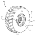
- Fig. 2
- is a perspective view of a wheel assembly,
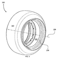
- Fig. 3
- is a perspective view of the wheel assembly of
Fig. 2 with a tire removed, - Fig. 4
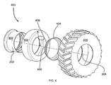
- is an exploded perspective view of the wheel assembly of
Fig. 3 , - Fig. 5
- is a partial cross-sectional view of the wheel assembly from
Fig. 2 , - Fig. 6
- is a partial exploded view of the wheel assembly of
Fig. 5 , - Fig. 7
- is an illustrative control system diagram of one embodiment of the wheel assembly,
- Fig. 8
- is an illustrative control system diagram of a different embodiment of the wheel assembly, and
- Fig. 9
- is an illustrative control system diagram of a wheel assembly with a pump coupled thereto.
- The embodiments of the present disclosure described below are not intended to be exhaustive or to limit the disclosure to the precise forms in the following detailed description. Rather, the embodiments are chosen and described so that others skilled in the art may appreciate and understand the principles and practices of the present disclosure.
- Referring to
Fig. 1 , aconventional tractor 100 is shown. While a conventional tractor is shown, this disclosure is not limited to such a machine. Rather, the teaching of this disclosure may be applicable to any wheel assembly of any type of vehicle, work machine or tractor. - The
tractor 100 may have achassis 102 coupled to at least onewheel assembly 104. Thetractor 100 in the embodiment ofFig. 1 shows onewheel assembly 104 coupled to thechassis 102 at afront end 110 and anotherwheel assembly 104 coupled to the chassis at aback end 114. In addition to thewheel assemblies 104, thechassis 102 may also have acabin 106 coupled thereto. Thecabin 106 may provide a location for a user to control a plurality of components through acontrol panel 116 that may be coupled to thechassis 102. Thecontrol panel 116 may have, among other things, a plurality of inputs that the user may engage to control the electrical, hydraulic, and/or mechanical components of thetractor 100. In one non-limiting example, a drive mechanism (not shown) may also be coupled to thechassis 102. Further, the user may selectively engage the work machine to provide torque to thewheel assembly 104. As torque is transferred to thewheel assembly 104, thewheel assembly 104 may rotate against an underlying surface to provide motion to thetractor 100. - Changing or modifying the tire pressure is conventionally achieved either through compressors or other pump assemblies that force fluid into the cavity of the tire/wheel assembly to increase the tire pressure. Utilizing standard compressors to fill the largevolume cavities can require a substantial amount of time to achieve a minimal increase in tire pressure. In order to more quickly increase the tire pressure, larger compressors may be used. However, these larger, conventional compressors are often too large to be locally mounted to the tractor or work machine.
- The teachings of this disclosure relate to compressing or otherwise positioning fluid within a chamber. Fluid can mean any type of gas or liquid and the term "fluid" should not be limited to meaning exclusively a gas or a liquid. In one embodiment, the surrounding atmosphere may be the fluid placed within the chamber. In a different embodiment, the fluid may be substantially nitrogen gas. In yet a different embodiment, the fluid may be partially a liquid and partially a gas. There are many forms of fluid that are applicable to the present disclosure; accordingly, the disclosure should not be limited to any one specific type of fluid.
- An apparatus is provided herein, and in particular, a compact system including a wheel assembly that increases the tire pressure of a tire relatively quickly.
- Referring now to
Fig. 2 , anisolated perspective view 200 of thewheel assembly 104 is shown. More particularly, arim 202 is shown coupled to atire 204. In this embodiment, therim 202 may be coupled to a drive system (not shown) of thetractor 100 to selectively engage the underlying surface through thetire 204. Avalve 206 is also shown inFig. 2 of thewheel assembly 104. In one embodiment, thevalve 206 may provide for a location to transfer a fluid from an area outside therim 202 to an area between therim 202 and thetire 204. As will become more apparent throughout this disclosure, the particular location of thevalve 206 is not limiting. In a different embodiment, there may not be avalve 206 located along the rim. In other aspects, there may be two or more valves for a given wheel assembly. - The
rim 202 andtire 204 may form an annular body concentrically disposed about arotation axis 208. Therotation axis 208 may be aligned with an axle (not shown) of thetractor 100. The axle may provide torque to therim 202 along therotation axis 208 to allow thetractor 100 to move along the underlying surface. In one embodiment, thetire 204 may have a tireinner radius 210 and a tireouter radius 212. The actual dimensions of the tireinner radius 210 and the tireouter radius 212 may vary depending on the particular needs of thetractor 100. In one embodiment, the tireinner radius 210 may be 450 millimeters and the tireouter radius 212 may be 1065 millimeters, but this disclosure is not limited to any particular dimension or size or shape of tire. Further, in one non-exclusive example, a cavity disposed between thetire 204 and therim 202 may have a volume of about 700 to 1100 liters. However, this disclosure is not limited to any particular volume of tire. - Referring now to
Fig. 3 , aperspective view 300 of thewheel assembly 104 with thetire 204 removed is shown. More specifically, abladder 302 is shown that may be positioned along an outer diameter of therim 202 and within the tire 204 (not shown inFig. 3 ). Thebladder 302 may be sized to fit within the cavity defined between thetire 204 and therim 202. Thebladder 302 may be pressurized with a desired fluid or otherwise contain a volume of fluid. - In
Fig. 4 , an explodedview 400 of thewheel assembly 104 is shown without thetire 204. The explodedview 400 more clearly shows a first outerradial surface 402 defined in part by therim 202. The first outerradial surface 402 may be a substantially impermeable cylindrical surface disposed about therotation axis 208. When thebladder 302 ortire 204 or both are coupled to therim 202, at least one substantially fluid-tight cavity may be created therebetween. In one non-exclusive embodiment, when thebladder 302 ortire 204 or both are coupled to therim 202, the passage of fluid from an area outside of the at least one cavity to an area within the at least one cavity may be operably controlled by thevalve 206. In some aspects, there may be two ormore valves 206 such that each can operably control fluid flow. - A
rim member 404 is also shown inFig. 4 . Therim member 404 may have an internal radius that is sized to be received by a portion of therim 202. That is to say, therim member 404 may at least partially slide over, or be press-fit into, a portion of the first outerradial surface 402. In one embodiment, therim member 404 may be removably coupled to therim 202 and provide a second outerradial surface 406, as shown inFig. 4 . In this embodiment, when therim member 404 is coupled to therim 202, thetire 204 and/orbladder 302 may be coupled to both therim 202 and therim member 404 to define at least one fluid-tight cavity therebetween. In an alternative embodiment, therim member 404 described above may not be a separate piece, but rather the secondradial surface 406 may be defined as part of therim 202 itself rather than requiring theseparate rim member 404. - In one embodiment, the
tire 204 may be composed of a rubber or other substantially similar material. The material may be sufficiently strong to withstand the pressure and driving conditions expected for any number of a plurality of applications. Further, the material of thetire 204 may deflect or compress as thetractor 100 or other work machine is exposed to different loads, road conditions, or road surfaces. - The
bladder 302 may also define a bladderouter radius 408. In one embodiment, the bladderouter radius 408 may be sized to be less than the tireouter radius 212. In this embodiment, the bladderouter radius 408 may be sufficient sized to allow thetire 204 to deflect towards therotation axis 208 during rotation thereof without contacting thebladder 302. In one non-exclusive embodiment, the bladderouter radius 408 is approximately 65% to 85% the tireouter radius 212. Other ranges may be possible in different embodiments. - In a further embodiment, the
bladder 302 may contact thetire 204 under certain conditions. More specifically, thebladder 302 may act as a supplementary or back-up cushion or support if thetire 204 deflects beyond a certain location. In yet another embodiment, thebladder 302 may have a bladderouter radius 408 that is large enough to allow thetractor 100 to travel along the underlying surface even when thetire 204 is insufficiently inflated. - A
sectional view 500 of thewheel assembly 104 is shown inFig. 5 . InFig. 5 , the lower portion of thebladder 302 is shown with broken lines to more clearly illustrate a firstinterior region 502. More specifically, the firstinterior region 502 is illustrated inFig. 5 . The firstinterior region 502 may be a substantially toroidal cavity defined between thetire 204, therim 202, and therim member 404. The radially inner portion of the firstinterior region 502 may be defined by the first outerradial surface 402 of therim 202 and the second outerradial surface 406 of therim member 404.interior tire walls 504 may define two sides of the firstinterior region 502 as thetire walls 504 extend radially away from therim 202. Along the tireouter radius 212, thetire walls 504 may terminate at atire tread 506 that connects each of the twotire walls 504 to one another. The firstinterior region 502 may create a toroidal cavity between the first outerradial surface 402, the second outerradial surface 406, thetire walls 504, and thetire tread 506. - Similarly, the
bladder 302 may be coupled to therim 202 to define a secondinterior region 508. The secondinterior region 508 may also be a substantially toroidal cavity defined between thebladder 302, therim 202, and therim member 404. The radially inner portion of the secondinterior region 508 may be defined by the first outerradial surface 402 of therim 202 and the second outerradial surface 406 of therim member 404.Bladder walls 510 may define two sides of the secondinterior region 508 as thebladder walls 510 extend radially away from therim 202. Along the bladderouter radius 408, thebladder walls 510 may terminate at abladder surface 512 that connects each of the twobladder walls 510 to one another. The secondinterior region 508 may create a toroidal cavity between the first outerradial surface 402, the second outerradial surface 406, thebladder walls 510, and thebladder surface 512. - A third
interior region 514 may also be defined by therim 202, therim member 404, thebladder 302, and thetire 204. In one non-limiting example, the thirdinterior region 514 may be defined by the portion of the first outerradial surface 402 between thebladder 302 and thetire 204, the portion of the second outerradial surface 406 between thebladder 302 and thetire 204, thetire walls 504, thetire tread 506, thebladder surface 512 and thebladder walls 510. More simply put, the thirdinterior region 514 is substantially the space between thebladder 302 and thetire 204 when both thebladder 302 and thetire 204 are coupled to therim 202. - The first, second, and third
interior regions rim 202 and therim member 404. In another embodiment, however, there may be norim member 404. In this embodiment, the second outerradial surface 406 described above for therim member 404 may be defined by a portion of therim 202. That is to say, instead of therim member 404 being a removable component, the structural elements of the rim member shown and described above may be formed by therim 202 as one integrally formed outer radial surface. - Referring now to
Fig. 6 , an explodedsection view 600 is shown. In the explodedsection view 600, afirst bead seat 602 is more clearly shown. Thefirst bead seat 602 may be a cylindrically-defined surface on therim 202. Thefirst bead seat 602 may be concentric with therotation axis 208 and spaced afirst radial distance 604 from therotation axis 208. - Similarly, the
rim member 404 may define asecond bead seat 606. Thesecond bead seat 606 may be a cylindrically-defined defined on therim member 404. Thesecond bead seat 606 may be concentric with therotation axis 208 and spaced asecond radial distance 608 from therotation axis 208. In one non-limiting example, thesecond radial distance 608 may be the same as thefirst radial distance 604. This, however, may differ in other examples. - The
tire 204 may have afirst tire bead 610 and asecond tire bead 612 that may be coupled to or disposed in contact with therim 202 along thefirst bead seat 602 and thesecond bead seat 606 respectively. The first andsecond tire bead tire 204 that has a radius substantially similar to thefirst radial distance 604 and thesecond radial distance 608 respectively. Thefirst tire bead 610 may be coupled along thefirst bead seat 602 and thesecond tire bead 612 may be coupled along thesecond bead seat 606 to provide a substantially fluid-tight connection between thetire 204 and therim 202. - Similarly, as shown in
Fig. 6 , thebladder 302 may define afirst bladder bead 614 and asecond bladder bead 616. Thefirst bladder bead 614 and thesecond bladder bead 616 may define an annularly-shaped aperture in thebladder 302 having a radius defined by a thirdradial distance 618. The thirdradial distance 618 may be less than the first and second radial distances. - The
rim 202 may also define athird bead seat 620 and afourth bead seat 622. The third and fourth bead seats 620, 622 may be substantially cylindrical surfaces that are concentric with therotation axis 208 and spaced by the thirdradial distance 618 from therotation axis 208. The third and fourth bead seats 620, 622 may correspond with the first andsecond bladder beads second bladder beads - One embodiment may also have a first
annular lip 624 disposed adjacent to, and extending radially away from, thefirst bead seat 602. Similarly, therim member 404 may define a secondannular lip 626 that is adjacent to, and extending radially away from, thesecond bead seat 606. The first and secondannular lips first tire bead 610 and thesecond tire bead 612, respectively, to ensure the proper axial alignment of the first andsecond tire beads rotation axis 208. - One embodiment may also have a third
annular lip 628 disposed adjacent to, and extending radially away from, thethird bead seat 620. Similarly, therim member 404 may define a fourthannular lip 630 that is adjacent to, and extending radially away from, thefourth bead seat 622. The third and fourthannular lip first bladder bead 614 and thesecond bladder bead 616 respectively, to ensure the proper axial alignment of the first andsecond bladder bead rotation axis 208. - In one non-exclusive embodiment, the first and second radial distances 604, 608 are substantially the same and the third
radial distance 618 is less than the first and secondradial distance bladder 302 may be coupled to therim 202 and therim member 404 at a radially inner portion (i.e. the third radial distance 618) of therim 202 relative to thetire 204. Further, thebladder 302 may be coupled to therim 202 at locations that are axially offset from the respective locations of thetire 204. - In one embodiment, the
bladder 302 may be placed between thetire walls 504 prior to positioning thetire 204 and thebladder 302 around therim 202. Thefirst tire bead 610 may then be positioned on thefirst bead seat 602 until thefirst tire bead 610 at least partially contacts the firstannular lip 624. Thefirst bladder bead 614 may then be similarly pressed onto thethird bead seat 620 until thefirst bladder bead 614 at least partially contacts the thirdannular lip 628. - Next, the
rim member 404 may be aligned with therim 202 and pressed onto therim 202. As therim member 404 is pressed onto therim 202,second bladder bead 616 may be positioned on thefourth bead seat 622 until thesecond bladder bead 616 at least partially contacts the fourthannular lip 630. At substantially the same time, thesecond tire bead 612 may be positioned on thesecond bead seat 606 until thesecond tire bead 612 substantially contacts the secondannular lip 626. Finally, therim member 404 may be coupled to therim 202 to provide a fluid-tight coupling between thetire 204, thebladder 302, and therim 202. In one embodiment, an O-ring 634 may be disposed between therim member 404 and therim 202 to further seal the secondinterior region 508 of thebladder 302. - In an alternative embodiment that is considered herein, the first and
second tire beads second bladder beads second bead seat first tire bead 610, thesecond tire bead 612, thefirst bladder bead 614, and thesecond bladder bead 616 are spaced thefirst radial distance 604 from therotation axis 208. Further, there may not be thethird bead seat 620 and thefourth bead seat 622. In this embodiment, thebladder 302 may be placed between thetire walls 504 before being slid over therim 202. Then, thefirst tire bead 610 and thefirst bladder bead 614 may be positioned on thefirst bead seat 602 until thefirst tire bead 610 at least partially contacts the firstannular lip 624 and thefirst bladder bead 614 is substantially adjacent to thefirst tire bead 610. Therim member 404 may then be positioned on therim 202 so that thesecond tire bead 612 and thesecond bladder bead 616 become disposed along thesecond bead seat 606. Therim member 404 may be positioned on the rim until thesecond tire bead 612 at least partially contacts the secondannular lip 626 and thesecond bladder bead 616 is substantially adjacent to thesecond tire bead 612. Finally, therim member 404 may be coupled to therim 202. - As described above, this disclosure is not limited to a rim that requires a rim member. When the
tire 204 and thebladder 302 share the first andsecond bead seat rim 202 may have thesecond bead seat 606 and the secondannular lip 626 integrally formed therein. In this embodiment, thetire 204 and thebladder 302 may be coupled to therim 202 by placing thebladder 302 between thetire walls 504 before stretching thetire 204 andbladder 302 over the first or secondannular lip tire 204 and thebladder 302 are positioned between the firstannular lip 624 and the secondannular lip 626, thefirst tire bead 610 and thefirst bladder bead 614 may become disposed along thefirst bead seat 602. Then thesecond tire bead 612 and thesecond bladder bead 616 may become disposed along thesecond bead seat 606. - In yet a different embodiment, the
bladder 302 may not require a bead seat or a bladder bead. In this embodiment, thebladder 302 may have a substantially circular cross-section and substantially encompass a toroidal cavity regardless of whether thebladder 302 is coupled to thetire 204. In this embodiment, thebladder 302 may have one valve (not shown) coupled thereto that allows thebladder 302 to be filled with a fluid and another valve (not shown) that allows the bladder to release fluid. Similarly, the valve for filling the bladder may be positioned through therim 202 so that thebladder 302 may be filled with fluid even when it is positioned between thetire 204 and therim 202. In one embodiment, the valve that releases fluid from the bladder may be selectively controlled electronically to release pressurized fluid from thebladder 302 into the cavity between thetire 204 and therim 202. - In
Fig. 7 , acontrol system 700 is shown. Thecontrol system 700 may have acontroller 702 that is electrically coupled to acompressor 704, afirst valve 706, asecond valve 708, athird valve 724, afirst sensor 710, asecond sensor 712, and athird sensor 714. - Further, the
controller 702 is in communication with auser interface 716 that is capable of communicating a user-desired tire pressure to thecontroller 702. Afirst communication link 718 may transfer electrical signals from thecontroller 702 to thecompressor 704, thefirst valve 706, thesecond valve 708, and thethird valve 724. Similarly, asecond communication link 720 may transfer electrical signals from the first, second, andthird sensors controller 702 indicating the pressure surrounding thesensors - In the
system 700 ofFig. 7 , thefirst valve 706 may have either a first position or a second position that is controlled by thecontroller 702. In the first position, thefirst valve 706 may fluidly isolate the secondinterior region 508 from the thirdinterior region 514. In the second position, thefirst valve 706 may fluidly couple the secondinterior region 508 with the thirdinterior region 514. In one non-limiting example, if the fluid in the secondinterior region 508 is at a higher pressure than the fluid in the thirdinterior region 514, thefirst valve 706 may be transitioned to the second position to allow the pressurized fluid of the secondinterior region 508 to flow into and increase the fluid pressure of the thirdinterior region 514. In other words, the fluid pressure in the secondinterior region 508 decreases while increasing the pressure in the thirdinterior region 514. - Similarly, the
second valve 708 may be positioned between atank 722 and the secondinterior region 508. Thetank 722 may accumulate compressed fluid supplied by thecompressor 704. Thesecond valve 708 may also have a first position and a second position. In the first position, thesecond valve 708 may fluidly isolate the secondinterior region 508 from thetank 722. However, when thesecond valve 708 is in the second position, thetank 722 may be fluidly coupled to the secondinterior region 508. When thesecond valve 708 is in the second position, a higher pressurized fluid may flow into the secondinterior region 508. - The
third valve 724 may be positioned between the thirdinterior region 514 and a surrounding atmosphere. Thethird valve 724 may also have a first position and a second position. In the first position, thethird valve 724 may fluidly isolate the thirdinterior region 514 from the atmosphere. However, when thethird valve 724 is in the second position, the thirdinterior region 514 may be fluidly coupled to the atmosphere. Accordingly, the pressurized fluid in the thirdinterior region 514 may begin exhausting to the surrounding atmosphere. - While a
tank 722 has been described as being coupled between thecompressor 704 and thesecond valve 708, in one embodiment there is notank 722. In this embodiment, thecompressor 704 may be directly fluidly coupled to thesecond valve 708. In this embodiment, thesecond valve 708 is transitioned to the second position at substantially the same time that thecompressor 704 is activated in order to properly supply compressed fluid to the secondinterior region 508. - In one embodiment, the
first sensor 710 may be disposed in the thirdinterior region 514, thesecond sensor 712 may be disposed in the secondinterior region 508, and thethird sensor 714 may be disposed in thetank 722. Each of therespective sensors controller 702 via the secondwire communication link 720 that is indicative of a detected pressure by the respective sensor. - In one embodiment, the
user interface 716 may be manipulated by a user to communicate a desired fluid pressure in any one of thetank 722, the secondinterior region 508, or the thirdinterior region 514 to thecontroller 702. In one example, the user may desire a maximum fluid pressure (or alternatively any desired fluid pressure) be provided in thetank 722. In this example, the user can manipulate theuser interface 716 to communicate the desired maximum pressure condition in thetank 722. Thecontroller 702 may then receive the current pressure signal from thethird sensor 714 to determine the fluid pressure in thetank 722. If thetank 722 is not already at the maximum fluid pressure, thecontroller 702 sends a signal to thesecond valve 708 to ensure that thetank 722 is fluidly isolated from the secondinterior region 508. Then, thecontroller 702 sends a signal to activate thecompressor 704 and provide compressed fluid to thetank 722. While thecompressor 704 is activated, thecontroller 702 may continuously monitor pressure readings from thethird sensor 714 until the maximum fluid pressure condition is met, at which point thecontroller 702 may deactivate thecompressor 704. - In a second example, the user may desire the second
interior region 508 be at a desired fluid pressure. In this example, the user may manipulate theuser interface 716 to communicate this desired fluid pressure to thecontroller 702. Thecontroller 702 can compare a pressure reading received from thesecond sensor 712 in the secondinterior region 508 with a pressure reading of thethird sensor 714 in thetank 722. If the pressure indicated by thethird sensor 714 is greater than the pressure indicated by thesecond sensor 712, thecontroller 702 may transition thesecond valve 708 to the second position to fluidly couple the secondinterior region 508 with thetank 722. As the secondinterior region 508 is fluidly coupled with thetank 722, thecontroller 702 may continue to monitor thesecond sensor 712 until the desired fluid pressure is achieved. Once the desired fluid pressure in the secondinterior region 508 is achieved, thesecond valve 708 may be returned to its first position, thereby fluidly isolating the secondinterior region 508 from thetank 722. If the fluid pressure in thetank 722 is not high enough, thecontroller 702 may further activate thecompressor 704 as described above. - In a third example, the user may desire the third
interior region 514 be raised from a minimum pressure to a driving pressure. In this example, the user may manipulate theuser interface 716 to communicate the need to fill the thirdinterior region 514 to the driving pressure. Thecontroller 702 may compare a pressure reading of thesecond sensor 712 in the secondinterior region 508 with a pressure reading of thefirst sensor 710 in the thirdinterior region 514. If the pressure indicated by thesecond sensor 712 is greater than the pressure indicated by thefirst sensor 710, thecontroller 702 may transition thefirst valve 706 to the second position to fluidly couple the secondinterior region 508 with the thirdinterior region 514. As the secondinterior region 508 is fluidly coupled with the thirdinterior region 514, thecontroller 702 may continue to monitor thefirst sensor 710 until the driving fluid pressure is reached. Once the driving fluid pressure in the thirdinterior region 514 is reached, thefirst valve 706 may be returned to the first position, thereby fluidly isolating the secondinterior region 508 from the thirdinterior region 514. - Alternatively, in a fourth example the user may desire the third
interior region 514 be lowered from the driving pressure to the minimum pressure. In this example the user may operate theuser interface 716 to communicate this to thecontroller 702. Thecontroller 702 may then take a pressure reading from thefirst sensor 710 to determine whether the current pressure in the thirdinterior region 514 is greater than the minimum pressure. If it is, thecontroller 702 may control thethird valve 724 to its second position to fluidly couple the thirdinterior region 514 with the surrounding atmosphere, thereby exhausting fluid from the thirdinterior region 514 and lowering the fluid pressure in the thirdinterior region 514. - In yet another aspect of the
system 700 ofFig. 7 , thevalves compressor 704 to directly provide pressurized fluid to the second and thirdinterior regions interior region 508 and thetank 722 do not contain higher pressure fluid, thevalves compressor 704 is activated to provide pressurized fluid to thetank 722, the secondinterior region 508, and the thirdinterior region 514 at substantially the same time. - While embodiments allowing the user to select pressure preferences in any of the
tank 722, the secondinterior region 508, and the thirdinterior region 514 have been described above, in one embodiment theuser interface 716 may only allow for the user to select the pressure in the thirdinterior region 514. In this embodiment, thecontroller 702 may monitor thesecond sensor 712 and thethird sensor 714 to ensure they remain at a maximum pressure threshold. If any one of thetank 722 or the secondinterior region 508 falls below the maximum threshold, thecontroller 702 activates thecompressor 704 and positions thesecond valve 708 in the position that corresponds with the area needing increased pressure. - In one non-exclusive embodiment, the
first valve 706 may be a high-flow valve. In this embodiment, the high-flowfirst valve 706 is positionable to transfer the high pressure fluid from the secondinterior region 508 into the thirdinterior region 514 in a substantially short period of time. The high-flowfirst valve 706 may allow the user to change the fluid pressure in the thirdinterior region 514 from the minimum pressure to the driving pressure in a short period of time. Further, any of the valves described herein may incorporate a high-flow valve and this disclosure is not limited to any particular type of valve. - In yet another embodiment, the
controller 702 may calculate an equilibrium pressure desired for the secondinterior region 508. The equilibrium pressure may be based on the current volume/pressure of the thirdinterior region 514, the volume of the secondinterior region 508, and the driving pressure of the thirdinterior region 514. The equilibrium pressure may be the fluid pressure required to be in the secondinterior region 508 in order to raise the current pressure of the thirdinterior region 514 to the driving pressure. - In one non-limiting example, the third
interior region 514 may be at about 10 PSI and have a volume of about 800 Liters. The secondinterior region 508 may have a volume of about 200 Liters. Further, the driving pressure of the third interior region may be about 15 PSI. In this example, thecontroller 702 calculates the equilibrium pressure to be the pressure required in the secondinterior region 508 that allows both the second and thirdinterior regions interior region 508 to the thirdinterior region 514 without requiring thecontroller 702 to monitor thefirst sensor 710 during the release. - In one embodiment, the
tire 204 that encompasses the thirdinterior region 514 may contain a fluid pressure of about 0 to 60 PSI while thebladder 302 that encompasses the secondinterior region 508 may contain a fluid pressure at about 0 to 150 PSI. - However, this disclosure is not limited to any particular pressure range. For example, in one embodiment the
bladder 302 may contain fluid at pressures in excess of 3.000 PSI. - Further, the pressure capabilities of the
bladder 302 may correlate with the bladder's 302 volume (i.e. the second interior region 508) compared to the volume of the thirdinterior region 514. That is to say, if thebladder 302 has a small volume compared to the third interior region 514 (i.e., bladder volume is ¼ the volume of the third interior region), thebladder 302 may need to contain high fluid pressures to provide a significant change in the fluid pressure of the thirdinterior region 514. Alternatively, if thebladder 302 defines a substantially similar volume as the thirdinterior region 514, thebladder 302 may not need to contain high fluid pressures because of the comparatively similar volume. - In a different embodiment shown in a
control system 800 inFig. 8 , asingle valve 802 may be used for fluidly coupling the secondinterior region 508, the thirdinterior region 514, thetank 722, and the atmosphere as described above forFig. 7 . Moreover, thevalve 802 may pressurize the secondinterior region 508 and the third interior region (or main chamber) 514 independently of one another. Thevalve 802 shown inFig. 8 may have a first position, a second position, a third position, a fourth position, and a fifth position. In the first position, thevalve 802 may substantially isolate (or fluidly decouple) the secondinterior region 508, the thirdinterior region 514, thetank 722 and/or thecompressor 704, and the surrounding atmosphere from one another. In the second position, thevalve 802 may fluidly couple the secondinterior region 508 with thetank 722 and/or thecompressor 704. In the third position, thevalve 802 may fluidly couple the secondinterior region 508 with the thirdinterior region 514. In the fourth position thevalve 802 may fluidly couple thetank 722 and/orcompressor 704 to the thirdinterior region 514. Finally, in the fifth position, the valve may fluidly couple the thirdinterior region 514 with the surrounding atmosphere to exhaust fluid pressure therefrom. Although not shown, thevalve 802 or a second valve may further be in communication with thecontroller 702 to exhaust fluid pressure from the secondinterior region 508 to the surrounding atmosphere. - While several valve and sensor configurations have been disclosed herein, this disclosure is not limited to any particular one. The teachings of this disclosure are understood to be applicable in a plurality of configurations. For example, in one embodiment there may be no
user interface 716. Rather, a sensor may indicate when the load condition of thetractor 100 has changed, and automatically adjust the fluid pressure in the thirdinterior region 514 to accommodate the different load. - In yet another aspect of this disclosure, instead of monitoring the pressure of the third
interior region 514, the deflection of thetire 204 may be monitored by a sensor instead. In this aspect, the sensor may be able to determine whether the fluid pressure in the thirdinterior region 514 needs to be increased based on the deflection reading of the sensor. Accordingly, thesecond sensor 712 may be a deflection sensor that measures the deflection of thetire 204. In yet another embodiment, the fluid in thetank 722, the secondinterior region 508, and the thirdinterior region 514 may be substantially nitrogen. - A different embodiment of the teachings disclosed herein is shown by the
system 900 ofFig. 9 . In thesystem 900 ofFig. 9 , apump 902 may be disposed between the secondinterior region 508 and the thirdinterior region 514. In this embodiment, when the user desires a lower pressure condition in the thirdinterior region 514, thepump 902 may force fluid located in the thirdinterior region 514 into the secondinterior region 508. Similarly, when the user desires an increased fluid pressure in the thirdinterior region 514, thepump 902 may transition fluid from the secondinterior region 508 into the thirdinterior region 514. - The embodiment of
Fig. 9 may have avalve 904 that allows fluid to be added to either the secondinterior region 508 or the thirdinterior region 514. However, the embodiment ofFig. 9 may not require either the secondinterior region 508 or the thirdinterior region 514 be filled through thevalve 904 at all. More specifically, thepump 902 may only transfer fluid between the secondinterior region 508 and the thirdinterior region 514 rather than utilize fluid from an outside source. In this embodiment, thevalve 904 may only be utilized if thewheel assembly 104 is leaking fluid out of the second or thirdinterior region
Claims (8)
- A wheel assembly, comprising a rim (202) having an outer radial surface (402); a tire (204) coupled to the rim (202) to define a first interior region (502) between the outer radial surface (402) and the tire (204); a bladder (302) coupled to the rim (202) to define a second interior region (508) between the outer radial surface (402) and the bladder (302); a third interior region (514) defined between the bladder (302) and the tire (204); and a valve (706) fluidly coupled to the second interior region (508) and the third interior region (514), the valve (706) being movable between a first position and a second position, wherein the bladder (302) is disposed in the first interior region (502), wherein the second interior region (508) and the third interior region (514) are fluidly isolated from one another when the valve (706) is in the first position, and wherein the second interior region (508) and the third interior region (514) are fluidly coupled to one another when the valve (706) is in the second position.
- The wheel assembly according to claim 1, characterized by further comprising a rotation axis (208) about which the rim (202) rotates, a first bead seat (602) formed by the rim (202) and spaced from the rotation axis (208) by a first radial distance (604), a second bead seat (606) spaced from the rotation axis (208) by a second radial distance (608) and offset by a distance from the first bead seat (602) in a direction parallel to the rotation axis (208), the first radial distance (604) and the second radial distance (608) being approximately the same, and a first tire bead (610) and a second tire bead (612) each formed on the tire (204), wherein the first tire bead (610) is in contact along the first bead seat (602) and the second tire bead (612) is in contact along the second bead seat (606).
- The wheel assembly according to claim 1 or 2, characterized by further comprising a rim member (404) removably coupled to the rim (202), wherein the first bead seat (602) is formed by the rim (202) and the second bead seat (606) is formed by the rim member (404).
- The wheel assembly according to at least one of claims 1 to 3, characterized by further comprising a first bladder bead (614) coupled to the rim (202) along the first bead seat (602), and a second bladder bead (616) coupled to the rim (202) along the second bead seat (606).
- The wheel assembly according to at least one of claims 1 to 4, characterized by further comprising a third bead seat (620) formed by the rim (202) and a fourth bead seat (622) formed by the rim member (404), wherein the third bead seat (620) and the fourth bead seat (622) are spaced by a third radial distance (618) from the rotation axis (208), the third radial distance (618) being less than the first and second radial distances (604, 608), and wherein the first bladder bead (614) is coupled to the rim (202) along the third bead seat (620) and the second bladder bead (616) is coupled to the rim (202) along the fourth bead seat (622).
- The wheel assembly according to at least one of claims 1 to 5, characterized in that the rim (202) forms a first annular lip (624) adjacent to the first bead seat (602), and the rim member (404) forms a second annular lip (626) adjacent to the second bead seat (606).
- The wheel assembly according to at least one of claims 1 to 6, characterized in that a first valve (706) and a second valve (708) is provided, wherein the first valve (706) is fluidly coupled to the second interior region (508) and the second valve (708) is fluidly coupled to the third interior region (514).
- The wheel assembly according to at least one of claims 1 to 7, characterized in that the valve (706) is coupled to the bladder (302) between the second interior region (508) and the third interior region (514).
Applications Claiming Priority (1)
| Application Number | Priority Date | Filing Date | Title |
|---|---|---|---|
| US14/824,665 US10017010B2 (en) | 2015-08-12 | 2015-08-12 | Fluid reservoir within a tire |
Publications (1)
| Publication Number | Publication Date |
|---|---|
| EP3132951A1 true EP3132951A1 (en) | 2017-02-22 |
Family
ID=56555273
Family Applications (1)
| Application Number | Title | Priority Date | Filing Date |
|---|---|---|---|
| EP16181748.1A Withdrawn EP3132951A1 (en) | 2015-08-12 | 2016-07-28 | Wheel assembly |
Country Status (2)
| Country | Link |
|---|---|
| US (1) | US10017010B2 (en) |
| EP (1) | EP3132951A1 (en) |
Cited By (3)
| Publication number | Priority date | Publication date | Assignee | Title |
|---|---|---|---|---|
| WO2017116631A1 (en) | 2015-12-29 | 2017-07-06 | Bridgestone Americas Tire Operations, Llc | Rapid tire inflation system with air compressor |
| GB2554459A (en) * | 2016-09-29 | 2018-04-04 | Energy Tech Institute Llp | Wheel assembly |
| US10953707B2 (en) | 2015-12-29 | 2021-03-23 | Bridgestone Americas Tire Operations, Llc | Air distribution system for rapid tire inflation |
Families Citing this family (6)
| Publication number | Priority date | Publication date | Assignee | Title |
|---|---|---|---|---|
| US10086803B2 (en) * | 2013-08-27 | 2018-10-02 | Ford Global Technologies, Llc | Pump with tire fill assist |
| GB201516024D0 (en) * | 2015-09-10 | 2015-10-28 | Agco Int Gmbh | Tyre in tyre systems |
| FR3046749B1 (en) * | 2016-01-19 | 2018-01-19 | Teleflow | INFLATION-DEFLATCH SYSTEM OF A TIRE |
| JP7042625B2 (en) * | 2018-01-15 | 2022-03-28 | 清水建設株式会社 | Fire extinguishing tires and fire extinguishing systems in construction workplaces |
| US11511743B2 (en) | 2019-12-17 | 2022-11-29 | Cnh Industrial Canada, Ltd. | System and method for controlling the speed of a work vehicle towing an implement |
| FR3115233B1 (en) * | 2020-10-16 | 2024-03-08 | Otico | Kit to form an agricultural tool from a wheel body or a tubular support |
Citations (9)
| Publication number | Priority date | Publication date | Assignee | Title |
|---|---|---|---|---|
| US2554815A (en) * | 1947-09-25 | 1951-05-29 | Dunlop Tire & Rubber Corp | Pneumatic tire and safety tube |
| US2731062A (en) * | 1953-12-02 | 1956-01-17 | Firestone Tire & Rubber Co | Tubeless tire |
| US2905221A (en) * | 1954-06-25 | 1959-09-22 | Firestone Tire & Rubber Co | Valve construction |
| DE7618034U1 (en) * | 1976-03-30 | 1977-06-16 | Monhoff, Karl-Heinz, 6000 Frankfurt | RUBBER OR PVC HOSE INSERTED IN THE RIM FOR AUTOMATIC TIRE AIR PRESSURE REGULATION |
| JPS58149806A (en) * | 1982-03-02 | 1983-09-06 | Nissan Motor Co Ltd | Pneumatic tire |
| DE4010711A1 (en) * | 1990-04-03 | 1991-10-17 | Ulrich Von Homeyer | Vehicle wheel with tyre pressure variation device - has pump element driven by rotation of wheel or by electric motor |
| US5538061A (en) * | 1994-04-08 | 1996-07-23 | Blair; Johnny E. | Dual chamber safety tire |
| US20130180641A1 (en) * | 2012-01-13 | 2013-07-18 | George Robert French | System and Method of Securing a Pneumatic Tire to a Rim |
| WO2016089593A1 (en) * | 2014-12-03 | 2016-06-09 | Bridgestone Americas Tire Operations, Llc | Rapid tire inflation system |
Family Cites Families (30)
| Publication number | Priority date | Publication date | Assignee | Title |
|---|---|---|---|---|
| US2898969A (en) * | 1957-03-11 | 1959-08-11 | Fred B Pfeiffer | Stabilizer means |
| US5180456A (en) | 1991-11-15 | 1993-01-19 | Eaton Corporation | Adaptive inflation control for vehicle central tire inflation system |
| US5301729A (en) * | 1992-07-27 | 1994-04-12 | Blair Johnny E | Dual chamber safety tire |
| US5535061A (en) | 1994-01-24 | 1996-07-09 | Juno Enterprises, Inc. | Rotary scanner |
| US5647927A (en) | 1995-06-21 | 1997-07-15 | United States Army Corps Of Engineers As Represented By The Secretary Of The Army | Central tire inflation controller |
| US5995895A (en) | 1997-07-15 | 1999-11-30 | Case Corporation | Control of vehicular systems in response to anticipated conditions predicted using predetermined geo-referenced maps |
| DE69709964T2 (en) | 1997-08-25 | 2002-08-29 | Goodyear Tire & Rubber | AGRICULTURAL TIRES WITH A GREAT CROSS-RATIO |
| DE19804249A1 (en) | 1998-02-04 | 1999-08-05 | Deere & Co | Device and method for adjusting the tire pressure on a vehicle |
| US6212464B1 (en) | 1998-10-06 | 2001-04-03 | Case Corporation | Slip control using an automatic central tire inflation system |
| US6236923B1 (en) | 1998-12-09 | 2001-05-22 | Caterpillar Inc. | Method and apparatus for controlling the inflation pressure of a pneumatic compactor |
| US6144295A (en) | 1998-12-11 | 2000-11-07 | Case Corporation | Automatic central tire inflation system |
| US6763288B2 (en) | 1999-07-30 | 2004-07-13 | Pirelli Pneumatici S.P.A. | Method and system for monitoring and/or controlling behavior of a vehicle by measuring deformations of its tires |
| DE10111532A1 (en) | 2001-03-10 | 2002-09-19 | Deere & Co | Tire pressure adjustment unit |
| DE10224939B4 (en) | 2002-05-31 | 2009-01-08 | Deere & Company, Moline | Driving-axle trailer |
| US7021720B1 (en) | 2003-08-07 | 2006-04-04 | Wilfred Yeggy | Till track vehicle |
| DE102004029736A1 (en) | 2004-06-19 | 2006-01-19 | Deere & Company, Moline | Tire pressure adjustment unit |
| US7302837B2 (en) | 2005-09-27 | 2007-12-04 | Cnh America Llc | Tire inflation system for use with an agricultural implement |
| JP2009023436A (en) * | 2007-07-18 | 2009-02-05 | Toyo Tire & Rubber Co Ltd | Pneumatic tire assembly |
| WO2010046905A1 (en) | 2008-09-12 | 2010-04-29 | Deere & Company | Traction device |
| GB0916233D0 (en) | 2009-09-16 | 2009-10-28 | Agco Gmbh | Tractor tyre inflation system |
| DK2503867T3 (en) | 2009-11-25 | 2018-07-23 | Univ Aarhus | SOIL COMPACT REDUCTION SYSTEM |
| US9248705B2 (en) | 2010-10-04 | 2016-02-02 | Agco International Gmbh | Rotary joint |
| GB201021929D0 (en) | 2010-12-23 | 2011-02-02 | Agco Internat Ltd | Tyre inflation |
| GB201021928D0 (en) | 2010-12-23 | 2011-02-02 | Agco Internat Ltd | Tyre inflation |
| GB201112568D0 (en) | 2011-07-22 | 2011-08-31 | Agco Int Gmbh | Tractor control system |
| US8843269B2 (en) | 2011-08-17 | 2014-09-23 | Deere & Company | Vehicle soil pressure management based on topography |
| US20130046418A1 (en) | 2011-08-17 | 2013-02-21 | Noel Wayne Anderson | V-foot tire management at fleet level |
| US20130054078A1 (en) | 2011-08-17 | 2013-02-28 | Noel Wayne Anderson | Dynamic traction adjustment |
| US20130046446A1 (en) | 2011-08-17 | 2013-02-21 | Noel Wayne Anderson | Vehicle stability and traction through v-foot shape change |
| GB2522038A (en) * | 2014-01-10 | 2015-07-15 | Caterpillar Inc | Tyre apparatus |
-
2015
- 2015-08-12 US US14/824,665 patent/US10017010B2/en active Active
-
2016
- 2016-07-28 EP EP16181748.1A patent/EP3132951A1/en not_active Withdrawn
Patent Citations (9)
| Publication number | Priority date | Publication date | Assignee | Title |
|---|---|---|---|---|
| US2554815A (en) * | 1947-09-25 | 1951-05-29 | Dunlop Tire & Rubber Corp | Pneumatic tire and safety tube |
| US2731062A (en) * | 1953-12-02 | 1956-01-17 | Firestone Tire & Rubber Co | Tubeless tire |
| US2905221A (en) * | 1954-06-25 | 1959-09-22 | Firestone Tire & Rubber Co | Valve construction |
| DE7618034U1 (en) * | 1976-03-30 | 1977-06-16 | Monhoff, Karl-Heinz, 6000 Frankfurt | RUBBER OR PVC HOSE INSERTED IN THE RIM FOR AUTOMATIC TIRE AIR PRESSURE REGULATION |
| JPS58149806A (en) * | 1982-03-02 | 1983-09-06 | Nissan Motor Co Ltd | Pneumatic tire |
| DE4010711A1 (en) * | 1990-04-03 | 1991-10-17 | Ulrich Von Homeyer | Vehicle wheel with tyre pressure variation device - has pump element driven by rotation of wheel or by electric motor |
| US5538061A (en) * | 1994-04-08 | 1996-07-23 | Blair; Johnny E. | Dual chamber safety tire |
| US20130180641A1 (en) * | 2012-01-13 | 2013-07-18 | George Robert French | System and Method of Securing a Pneumatic Tire to a Rim |
| WO2016089593A1 (en) * | 2014-12-03 | 2016-06-09 | Bridgestone Americas Tire Operations, Llc | Rapid tire inflation system |
Cited By (5)
| Publication number | Priority date | Publication date | Assignee | Title |
|---|---|---|---|---|
| WO2017116631A1 (en) | 2015-12-29 | 2017-07-06 | Bridgestone Americas Tire Operations, Llc | Rapid tire inflation system with air compressor |
| EP3397532A4 (en) * | 2015-12-29 | 2019-08-21 | Bridgestone Americas Tire Operations, LLC | Rapid tire inflation system with air compressor |
| US10953707B2 (en) | 2015-12-29 | 2021-03-23 | Bridgestone Americas Tire Operations, Llc | Air distribution system for rapid tire inflation |
| US11021023B2 (en) | 2015-12-29 | 2021-06-01 | Bridgestone Americas Tire Operations, Llc | Rapid tire inflation system with air compressor |
| GB2554459A (en) * | 2016-09-29 | 2018-04-04 | Energy Tech Institute Llp | Wheel assembly |
Also Published As
| Publication number | Publication date |
|---|---|
| US20170043623A1 (en) | 2017-02-16 |
| US10017010B2 (en) | 2018-07-10 |
Similar Documents
| Publication | Publication Date | Title |
|---|---|---|
| US10017010B2 (en) | Fluid reservoir within a tire | |
| CN110573355B (en) | Load-based tire inflation system for heavy-duty vehicles | |
| AU2011271099B2 (en) | Rotary air connection with central valve for tire inflation system | |
| US6668888B1 (en) | Central tire inflation system for steering drive axle | |
| US4498515A (en) | Onboard tire inflation system | |
| US20130276902A1 (en) | Central Tire Inflation Wheel Assembly and Valve | |
| EP3227127B1 (en) | Rapid tire inflation system | |
| EP2021194B1 (en) | Tire risk judging device of wheel assembly for vehicle | |
| KR20120094498A (en) | Central tire inflation wheel assembly, valve and central tire inflation system | |
| US10661612B2 (en) | Wheel valve arrangement and tire pressure control system having at least one such wheel valve arrangement | |
| EP3318426A1 (en) | Pneumatically controllable valve assembly, tire inflation system, and methods of operating the valve assembly and the tire inflation system | |
| JP6399564B2 (en) | Valve assembly for tire pressure management system | |
| US10953707B2 (en) | Air distribution system for rapid tire inflation | |
| US20130146193A1 (en) | Tire pressure equalization system | |
| JPH02106412A (en) | Ctis controller control method thereof | |
| CN106427414A (en) | Valve stem-based air maintenance tire and method | |
| US10377188B2 (en) | Tyre pressure regulating device | |
| US10358011B2 (en) | Dynamic weight shift suspension system | |
| EP3288784B1 (en) | Tire pressure management system and method of decreasing tire pressure | |
| US11345195B2 (en) | Automatic pressure valve for inflation / deflation of a pneumatic arrangement | |
| US6457502B1 (en) | Dual tire pressure balance system | |
| CN111836732B (en) | Rotation transmission device for transmitting control pressure and/or operating pressure to a wheel hub or a wheel received by a wheel hub | |
| US20230026449A1 (en) | Wheel unit of a vehicle and a valve assembly for a wheel unit | |
| WO2021133296A1 (en) | Tyre pressure regulation system | |
| JP2007118873A (en) | Pneumatic tire, tire and rim wheel assembly, and vehicle |
Legal Events
| Date | Code | Title | Description |
|---|---|---|---|
| PUAI | Public reference made under article 153(3) epc to a published international application that has entered the european phase |
Free format text: ORIGINAL CODE: 0009012 |
|
| AK | Designated contracting states |
Kind code of ref document: A1 Designated state(s): AL AT BE BG CH CY CZ DE DK EE ES FI FR GB GR HR HU IE IS IT LI LT LU LV MC MK MT NL NO PL PT RO RS SE SI SK SM TR |
|
| AX | Request for extension of the european patent |
Extension state: BA ME |
|
| 17P | Request for examination filed |
Effective date: 20170822 |
|
| RBV | Designated contracting states (corrected) |
Designated state(s): AL AT BE BG CH CY CZ DE DK EE ES FI FR GB GR HR HU IE IS IT LI LT LU LV MC MK MT NL NO PL PT RO RS SE SI SK SM TR |
|
| STAA | Information on the status of an ep patent application or granted ep patent |
Free format text: STATUS: THE APPLICATION IS DEEMED TO BE WITHDRAWN |
|
| 18D | Application deemed to be withdrawn |
Effective date: 20170823 |