EP3132909A1 - Method for manufacturing decorative parts - Google Patents
Method for manufacturing decorative parts Download PDFInfo
- Publication number
- EP3132909A1 EP3132909A1 EP15181568.5A EP15181568A EP3132909A1 EP 3132909 A1 EP3132909 A1 EP 3132909A1 EP 15181568 A EP15181568 A EP 15181568A EP 3132909 A1 EP3132909 A1 EP 3132909A1
- Authority
- EP
- European Patent Office
- Prior art keywords
- pressure
- tool
- carrier element
- plastic
- casting
- Prior art date
- Legal status (The legal status is an assumption and is not a legal conclusion. Google has not performed a legal analysis and makes no representation as to the accuracy of the status listed.)
- Granted
Links
- 238000000034 method Methods 0.000 title claims abstract description 40
- 238000004519 manufacturing process Methods 0.000 title claims abstract description 13
- 238000005266 casting Methods 0.000 claims abstract description 31
- 239000004033 plastic Substances 0.000 claims abstract description 27
- 229920003023 plastic Polymers 0.000 claims abstract description 27
- 239000004814 polyurethane Substances 0.000 claims description 8
- 229920002635 polyurethane Polymers 0.000 claims description 6
- 238000007789 sealing Methods 0.000 claims description 3
- 239000002991 molded plastic Substances 0.000 claims 1
- 239000000463 material Substances 0.000 description 4
- 239000010985 leather Substances 0.000 description 3
- 230000000694 effects Effects 0.000 description 2
- 230000002349 favourable effect Effects 0.000 description 2
- 239000000835 fiber Substances 0.000 description 2
- 238000001746 injection moulding Methods 0.000 description 2
- 229920000642 polymer Polymers 0.000 description 2
- 229920000049 Carbon (fiber) Polymers 0.000 description 1
- XAGFODPZIPBFFR-UHFFFAOYSA-N aluminium Chemical compound [Al] XAGFODPZIPBFFR-UHFFFAOYSA-N 0.000 description 1
- 229910052782 aluminium Inorganic materials 0.000 description 1
- 239000004917 carbon fiber Substances 0.000 description 1
- 238000011161 development Methods 0.000 description 1
- 230000018109 developmental process Effects 0.000 description 1
- 238000007730 finishing process Methods 0.000 description 1
- 239000011888 foil Substances 0.000 description 1
- 239000007788 liquid Substances 0.000 description 1
- VNWKTOKETHGBQD-UHFFFAOYSA-N methane Chemical compound C VNWKTOKETHGBQD-UHFFFAOYSA-N 0.000 description 1
- 238000012805 post-processing Methods 0.000 description 1
- 239000003566 sealing material Substances 0.000 description 1
- 239000000243 solution Substances 0.000 description 1
- 230000007704 transition Effects 0.000 description 1
- -1 veneer Substances 0.000 description 1
- 239000002023 wood Substances 0.000 description 1
Images
Classifications
-
- B—PERFORMING OPERATIONS; TRANSPORTING
- B29—WORKING OF PLASTICS; WORKING OF SUBSTANCES IN A PLASTIC STATE IN GENERAL
- B29C—SHAPING OR JOINING OF PLASTICS; SHAPING OF MATERIAL IN A PLASTIC STATE, NOT OTHERWISE PROVIDED FOR; AFTER-TREATMENT OF THE SHAPED PRODUCTS, e.g. REPAIRING
- B29C45/00—Injection moulding, i.e. forcing the required volume of moulding material through a nozzle into a closed mould; Apparatus therefor
- B29C45/14—Injection moulding, i.e. forcing the required volume of moulding material through a nozzle into a closed mould; Apparatus therefor incorporating preformed parts or layers, e.g. injection moulding around inserts or for coating articles
- B29C45/14065—Positioning or centering articles in the mould
-
- B—PERFORMING OPERATIONS; TRANSPORTING
- B29—WORKING OF PLASTICS; WORKING OF SUBSTANCES IN A PLASTIC STATE IN GENERAL
- B29C—SHAPING OR JOINING OF PLASTICS; SHAPING OF MATERIAL IN A PLASTIC STATE, NOT OTHERWISE PROVIDED FOR; AFTER-TREATMENT OF THE SHAPED PRODUCTS, e.g. REPAIRING
- B29C43/00—Compression moulding, i.e. applying external pressure to flow the moulding material; Apparatus therefor
- B29C43/02—Compression moulding, i.e. applying external pressure to flow the moulding material; Apparatus therefor of articles of definite length, i.e. discrete articles
- B29C43/18—Compression moulding, i.e. applying external pressure to flow the moulding material; Apparatus therefor of articles of definite length, i.e. discrete articles incorporating preformed parts or layers, e.g. compression moulding around inserts or for coating articles
-
- B—PERFORMING OPERATIONS; TRANSPORTING
- B29—WORKING OF PLASTICS; WORKING OF SUBSTANCES IN A PLASTIC STATE IN GENERAL
- B29C—SHAPING OR JOINING OF PLASTICS; SHAPING OF MATERIAL IN A PLASTIC STATE, NOT OTHERWISE PROVIDED FOR; AFTER-TREATMENT OF THE SHAPED PRODUCTS, e.g. REPAIRING
- B29C41/00—Shaping by coating a mould, core or other substrate, i.e. by depositing material and stripping-off the shaped article; Apparatus therefor
- B29C41/02—Shaping by coating a mould, core or other substrate, i.e. by depositing material and stripping-off the shaped article; Apparatus therefor for making articles of definite length, i.e. discrete articles
- B29C41/22—Making multilayered or multicoloured articles
-
- B—PERFORMING OPERATIONS; TRANSPORTING
- B29—WORKING OF PLASTICS; WORKING OF SUBSTANCES IN A PLASTIC STATE IN GENERAL
- B29C—SHAPING OR JOINING OF PLASTICS; SHAPING OF MATERIAL IN A PLASTIC STATE, NOT OTHERWISE PROVIDED FOR; AFTER-TREATMENT OF THE SHAPED PRODUCTS, e.g. REPAIRING
- B29C41/00—Shaping by coating a mould, core or other substrate, i.e. by depositing material and stripping-off the shaped article; Apparatus therefor
- B29C41/24—Shaping by coating a mould, core or other substrate, i.e. by depositing material and stripping-off the shaped article; Apparatus therefor for making articles of indefinite length
- B29C41/28—Shaping by coating a mould, core or other substrate, i.e. by depositing material and stripping-off the shaped article; Apparatus therefor for making articles of indefinite length by depositing flowable material on an endless belt
-
- B—PERFORMING OPERATIONS; TRANSPORTING
- B29—WORKING OF PLASTICS; WORKING OF SUBSTANCES IN A PLASTIC STATE IN GENERAL
- B29C—SHAPING OR JOINING OF PLASTICS; SHAPING OF MATERIAL IN A PLASTIC STATE, NOT OTHERWISE PROVIDED FOR; AFTER-TREATMENT OF THE SHAPED PRODUCTS, e.g. REPAIRING
- B29C41/00—Shaping by coating a mould, core or other substrate, i.e. by depositing material and stripping-off the shaped article; Apparatus therefor
- B29C41/24—Shaping by coating a mould, core or other substrate, i.e. by depositing material and stripping-off the shaped article; Apparatus therefor for making articles of indefinite length
- B29C41/32—Making multilayered or multicoloured articles
-
- B—PERFORMING OPERATIONS; TRANSPORTING
- B29—WORKING OF PLASTICS; WORKING OF SUBSTANCES IN A PLASTIC STATE IN GENERAL
- B29C—SHAPING OR JOINING OF PLASTICS; SHAPING OF MATERIAL IN A PLASTIC STATE, NOT OTHERWISE PROVIDED FOR; AFTER-TREATMENT OF THE SHAPED PRODUCTS, e.g. REPAIRING
- B29C41/00—Shaping by coating a mould, core or other substrate, i.e. by depositing material and stripping-off the shaped article; Apparatus therefor
- B29C41/34—Component parts, details or accessories; Auxiliary operations
- B29C41/36—Feeding the material on to the mould, core or other substrate
-
- B—PERFORMING OPERATIONS; TRANSPORTING
- B29—WORKING OF PLASTICS; WORKING OF SUBSTANCES IN A PLASTIC STATE IN GENERAL
- B29C—SHAPING OR JOINING OF PLASTICS; SHAPING OF MATERIAL IN A PLASTIC STATE, NOT OTHERWISE PROVIDED FOR; AFTER-TREATMENT OF THE SHAPED PRODUCTS, e.g. REPAIRING
- B29C43/00—Compression moulding, i.e. applying external pressure to flow the moulding material; Apparatus therefor
- B29C43/02—Compression moulding, i.e. applying external pressure to flow the moulding material; Apparatus therefor of articles of definite length, i.e. discrete articles
- B29C43/10—Isostatic pressing, i.e. using non-rigid pressure-exerting members against rigid parts or dies
-
- B—PERFORMING OPERATIONS; TRANSPORTING
- B29—WORKING OF PLASTICS; WORKING OF SUBSTANCES IN A PLASTIC STATE IN GENERAL
- B29C—SHAPING OR JOINING OF PLASTICS; SHAPING OF MATERIAL IN A PLASTIC STATE, NOT OTHERWISE PROVIDED FOR; AFTER-TREATMENT OF THE SHAPED PRODUCTS, e.g. REPAIRING
- B29C45/00—Injection moulding, i.e. forcing the required volume of moulding material through a nozzle into a closed mould; Apparatus therefor
- B29C45/03—Injection moulding apparatus
-
- B—PERFORMING OPERATIONS; TRANSPORTING
- B29—WORKING OF PLASTICS; WORKING OF SUBSTANCES IN A PLASTIC STATE IN GENERAL
- B29C—SHAPING OR JOINING OF PLASTICS; SHAPING OF MATERIAL IN A PLASTIC STATE, NOT OTHERWISE PROVIDED FOR; AFTER-TREATMENT OF THE SHAPED PRODUCTS, e.g. REPAIRING
- B29C45/00—Injection moulding, i.e. forcing the required volume of moulding material through a nozzle into a closed mould; Apparatus therefor
- B29C45/17—Component parts, details or accessories; Auxiliary operations
- B29C45/76—Measuring, controlling or regulating
-
- B—PERFORMING OPERATIONS; TRANSPORTING
- B29—WORKING OF PLASTICS; WORKING OF SUBSTANCES IN A PLASTIC STATE IN GENERAL
- B29C—SHAPING OR JOINING OF PLASTICS; SHAPING OF MATERIAL IN A PLASTIC STATE, NOT OTHERWISE PROVIDED FOR; AFTER-TREATMENT OF THE SHAPED PRODUCTS, e.g. REPAIRING
- B29C45/00—Injection moulding, i.e. forcing the required volume of moulding material through a nozzle into a closed mould; Apparatus therefor
- B29C45/0053—Injection moulding, i.e. forcing the required volume of moulding material through a nozzle into a closed mould; Apparatus therefor combined with a final operation, e.g. shaping
- B29C2045/0079—Injection moulding, i.e. forcing the required volume of moulding material through a nozzle into a closed mould; Apparatus therefor combined with a final operation, e.g. shaping applying a coating or covering
-
- B—PERFORMING OPERATIONS; TRANSPORTING
- B29—WORKING OF PLASTICS; WORKING OF SUBSTANCES IN A PLASTIC STATE IN GENERAL
- B29C—SHAPING OR JOINING OF PLASTICS; SHAPING OF MATERIAL IN A PLASTIC STATE, NOT OTHERWISE PROVIDED FOR; AFTER-TREATMENT OF THE SHAPED PRODUCTS, e.g. REPAIRING
- B29C2945/00—Indexing scheme relating to injection moulding, i.e. forcing the required volume of moulding material through a nozzle into a closed mould
- B29C2945/76—Measuring, controlling or regulating
- B29C2945/76494—Controlled parameter
- B29C2945/76498—Pressure
-
- B—PERFORMING OPERATIONS; TRANSPORTING
- B29—WORKING OF PLASTICS; WORKING OF SUBSTANCES IN A PLASTIC STATE IN GENERAL
- B29C—SHAPING OR JOINING OF PLASTICS; SHAPING OF MATERIAL IN A PLASTIC STATE, NOT OTHERWISE PROVIDED FOR; AFTER-TREATMENT OF THE SHAPED PRODUCTS, e.g. REPAIRING
- B29C2945/00—Indexing scheme relating to injection moulding, i.e. forcing the required volume of moulding material through a nozzle into a closed mould
- B29C2945/76—Measuring, controlling or regulating
- B29C2945/76655—Location of control
- B29C2945/76772—Inserts
-
- B—PERFORMING OPERATIONS; TRANSPORTING
- B29—WORKING OF PLASTICS; WORKING OF SUBSTANCES IN A PLASTIC STATE IN GENERAL
- B29C—SHAPING OR JOINING OF PLASTICS; SHAPING OF MATERIAL IN A PLASTIC STATE, NOT OTHERWISE PROVIDED FOR; AFTER-TREATMENT OF THE SHAPED PRODUCTS, e.g. REPAIRING
- B29C33/00—Moulds or cores; Details thereof or accessories therefor
- B29C33/0038—Moulds or cores; Details thereof or accessories therefor with sealing means or the like
-
- B—PERFORMING OPERATIONS; TRANSPORTING
- B29—WORKING OF PLASTICS; WORKING OF SUBSTANCES IN A PLASTIC STATE IN GENERAL
- B29C—SHAPING OR JOINING OF PLASTICS; SHAPING OF MATERIAL IN A PLASTIC STATE, NOT OTHERWISE PROVIDED FOR; AFTER-TREATMENT OF THE SHAPED PRODUCTS, e.g. REPAIRING
- B29C33/00—Moulds or cores; Details thereof or accessories therefor
- B29C33/12—Moulds or cores; Details thereof or accessories therefor with incorporated means for positioning inserts, e.g. labels
-
- B—PERFORMING OPERATIONS; TRANSPORTING
- B29—WORKING OF PLASTICS; WORKING OF SUBSTANCES IN A PLASTIC STATE IN GENERAL
- B29C—SHAPING OR JOINING OF PLASTICS; SHAPING OF MATERIAL IN A PLASTIC STATE, NOT OTHERWISE PROVIDED FOR; AFTER-TREATMENT OF THE SHAPED PRODUCTS, e.g. REPAIRING
- B29C45/00—Injection moulding, i.e. forcing the required volume of moulding material through a nozzle into a closed mould; Apparatus therefor
- B29C45/14—Injection moulding, i.e. forcing the required volume of moulding material through a nozzle into a closed mould; Apparatus therefor incorporating preformed parts or layers, e.g. injection moulding around inserts or for coating articles
- B29C45/14836—Preventing damage of inserts during injection, e.g. collapse of hollow inserts, breakage
-
- B—PERFORMING OPERATIONS; TRANSPORTING
- B29—WORKING OF PLASTICS; WORKING OF SUBSTANCES IN A PLASTIC STATE IN GENERAL
- B29C—SHAPING OR JOINING OF PLASTICS; SHAPING OF MATERIAL IN A PLASTIC STATE, NOT OTHERWISE PROVIDED FOR; AFTER-TREATMENT OF THE SHAPED PRODUCTS, e.g. REPAIRING
- B29C67/00—Shaping techniques not covered by groups B29C39/00 - B29C65/00, B29C70/00 or B29C73/00
- B29C67/24—Shaping techniques not covered by groups B29C39/00 - B29C65/00, B29C70/00 or B29C73/00 characterised by the choice of material
- B29C67/246—Moulding high reactive monomers or prepolymers, e.g. by reaction injection moulding [RIM], liquid injection moulding [LIM]
-
- B—PERFORMING OPERATIONS; TRANSPORTING
- B29—WORKING OF PLASTICS; WORKING OF SUBSTANCES IN A PLASTIC STATE IN GENERAL
- B29K—INDEXING SCHEME ASSOCIATED WITH SUBCLASSES B29B, B29C OR B29D, RELATING TO MOULDING MATERIALS OR TO MATERIALS FOR MOULDS, REINFORCEMENTS, FILLERS OR PREFORMED PARTS, e.g. INSERTS
- B29K2075/00—Use of PU, i.e. polyureas or polyurethanes or derivatives thereof, as moulding material
-
- B—PERFORMING OPERATIONS; TRANSPORTING
- B29—WORKING OF PLASTICS; WORKING OF SUBSTANCES IN A PLASTIC STATE IN GENERAL
- B29K—INDEXING SCHEME ASSOCIATED WITH SUBCLASSES B29B, B29C OR B29D, RELATING TO MOULDING MATERIALS OR TO MATERIALS FOR MOULDS, REINFORCEMENTS, FILLERS OR PREFORMED PARTS, e.g. INSERTS
- B29K2105/00—Condition, form or state of moulded material or of the material to be shaped
- B29K2105/25—Solid
- B29K2105/251—Particles, powder or granules
-
- B—PERFORMING OPERATIONS; TRANSPORTING
- B29—WORKING OF PLASTICS; WORKING OF SUBSTANCES IN A PLASTIC STATE IN GENERAL
- B29L—INDEXING SCHEME ASSOCIATED WITH SUBCLASS B29C, RELATING TO PARTICULAR ARTICLES
- B29L2031/00—Other particular articles
- B29L2031/30—Vehicles, e.g. ships or aircraft, or body parts thereof
- B29L2031/3005—Body finishings
Definitions
- the invention relates to a method for the production of trim parts with a rear-side plastic carrier element and a plastic upper layer to be applied to the front side in the casting process.
- the invention also relates to a casting tool adapted for the method.
- Decorative parts are used in vehicle interiors as diaphragm elements and have a support element for attachment to the vehicle and optionally applied thereto and facing the visible side material layers, such as wood veneer layers, aluminum layers, carbon fiber mats or Leather on.
- the material layers are covered with plastic in the plastic casting tool, which forms the visible side of the trim part as an upper layer.
- the carrier element deforms back into its original position and the local enlargements of the component wall thickness become visible as an overhang in the opposite direction, practically as a hill on the visible side. Differences in the component wall thickness of just a few micrometers are already sufficient to be detected by the human eye. The differences in the component wall thickness must therefore be removed consuming with additional finishing processes again.
- the invention is therefore based on the object to provide a method, are avoided with the post-processing steps after the Studentsg suedungsrea with plastic and directly in the casting a flat surface is achieved. It is another object of the invention to provide a corresponding casting tool.
- a method for producing decorative parts with a rear-side plastic support element is proposed, which is poured over a casting mold for producing a top layer on a front side visible under process pressure with plastic, wherein the carrier element fixed in the casting mold and at least during the production of the top layer back and in the direction of the top layer to be produced on the front side, pressure is applied which counteracts the process pressure when casting over with plastic.
- the carrier element in the casting tool surface in particular over the entire surface in the direction of the front side to be produced on the upper layer is pressurized.
- the two-dimensional pressure stabilizes the carrier element in all areas during the overmolding process and reliably prevents buckling over the entire surface.
- the pressure is generated by pressurized gas, in particular compressed air, which is pressed into a cavity between an upper tool and the carrier element.
- pressurized gas in particular compressed air
- Compressed gas or compressed air has the particular advantage that it / she leaves no residue on the carrier element in contrast to all liquids and easy to handle.
- Compressed air is the most economical variant.
- a seal is arranged between the upper tool and the carrier element which seals the cavity at least during the production of the upper layer.
- the seal can be integrated on the tool or the carrier element or provided as an extra component.
- the maximum pressure is greater than or equal to the maximum process pressure during pouring. This ensures that bulging in the direction of the rear side of the carrier element is precluded.
- maximum pressure for example, 30 bar are applied to injection-molded polymer carrier elements.
- the pressure is maintained as long as the process pressure of the overflow is effective.
- the pressure may also act until the plastic molded top layer has cured.
- a control is advantageously provided. This also makes it possible for the pressure to be applied in several pressure stages with different pressure values. This makes it possible that the applied pressure is gradually reduced after completion of the over-pouring, in order to exclude as much as possible deformations on the carrier element.
- the process is used with polyurethane as Studentsg facedungs plastic, where both compact, hard, soft or foamed PUR systems can be used.
- the plastics can be transparent, semi-transparent or even colored.
- Also part of the invention is a adapted to carry out the manufacturing method described above casting tool with an upper tool and a lower tool, which have a receiving cavity for the support member in the closed state, which is pourable on a pointing to the lower tool visible side with plastic, wherein the upper tool a extending from the receiving cavity outwardly extending passage to which a compressed gas generator, preferably compressed air generator, is connectable, so that the receiving cavity is at least partially pressurized gas, in particular compressed air acted upon.
- a compressed gas generator preferably compressed air generator
- a groove is provided in the upper tool on a directed towards the lower tool inside a groove into which a seal for sealing the cavity between the support member and the upper tool can be introduced.
- the casting tool itself has the compressed gas generator. This can be achieved, for example, by integrating an air compressor which communicates with the passage in the upper tool.
- the control can also be integrated into the casting tool in order to control the height and action time of the pressure applied by the compressed gas generator, in particular the compressed air generator.
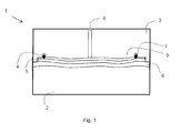
- FIG. 1 is an example of a schematic side view of a two-part casting tool 1 with an upper tool 3 and a lower tool 2 shown. Between the upper tool 3 and the lower tool 2, a receiving cavity is formed in the closed state shown, in which the carrier element 5 is inserted and fixed, so that the receiving cavity between the carrier element 5 and lower tool 2 a space 6 and between carrier element 5 and upper tool 3, a cavity. 9 forms.
- the carrier element 5 is poured over in the casting mold 1 on its side facing the lower tool 2 visible side to produce the upper layer with polyurethane under process pressure, wherein the process pressure acts in the direction of the upper tool 3.
- the upper tool has a from the receiving cavity or the cavity 9 outwardly extending passage 8 to which a compressor, not shown, is connected to the support member 5 at least during the generation of the upper layer back and in the direction of the lower tool 2, ie the upper side to be produced on the front side, to act on compressed air with a pressure that counteracts the process pressure when pouring plastic over.
- a seal 4 is inserted between the carrier element 5 and the upper tool 3, which partially extends in a groove 7 formed on the upper tool 3 and directed towards the lower tool 2.
- the injection-molded support element with material layer lying on the visible side is fixed in the casting mold 1 in such a way that the cavity 9 is sealed, and then via the usual process pressure polyurethane pressed into the free space 6.
- a surface pressure acting on the carrier element 5 is generated and held by way of the passage 8 by means of compressed air until the process pressure can be reduced.
- the pressure of the compressed air can be adjusted in several pressure stages. The time of the pressure application is variable and adaptable to the process of plastic or polyurethane introduction via a controller, not shown.
- the invention is not limited in its execution to the above-mentioned preferred embodiments. Rather, a number of variants is conceivable, which makes use of the illustrated solution even with fundamentally different types of use.
- shapes and thicknesses of the carrier element and the plastic layer to be applied are variable.
- support structures homogeneous or multi-layered
- support wall thicknesses are variable.
- PUR systems compact, foamed, hard, soft
- a variable arrangement of the seal for example on the casting tool or on the carrier element, different sealing materials and variable surface structures.
Landscapes
- Engineering & Computer Science (AREA)
- Mechanical Engineering (AREA)
- Manufacturing & Machinery (AREA)
- Casting Or Compression Moulding Of Plastics Or The Like (AREA)
Abstract
Die Erfindung betrifft ein Verfahren zum Herstellen von Zierteilen mit einem rückseitigen Kunststoff-Trägerelement, das in einem Gießwerkzeug zur Erzeugung einer Oberschicht auf einer vorderseitigen Sichtseite unter Prozessdruck mit Kunststoff übergossen wird, dadurch gekennzeichnet, dass das Trägerelement in dem Gießwerkzeug fixiert und zumindest während der Erzeugung der Oberschicht rückseitig und in Richtung der auf der vorderseitigen Sichtseite zu erzeugenden Oberschicht mit Druck beaufschlagt wird, der dem Prozessdruck beim Übergießen mit Kunststoff entgegenwirkt.The invention relates to a method for producing trim parts with a rear plastic carrier element, which is poured over in a casting tool for producing a top layer on a front side visible under process pressure with plastic, characterized in that the carrier element fixed in the casting mold and at least during production the upper layer is pressurized on the reverse side and in the direction of the upper layer to be produced on the front side of the visible side, which counteracts the process pressure when casting over with plastic.
Description
Die Erfindung betrifft ein Verfahren zur Herstellung von Zierteilen mit einem rückseitigen Kunststoff-Trägerelement und einer auf die Vorderseite im Gießverfahren aufzubringenden Kunststoff-Oberschicht. Auch betrifft die Erfindung ein für das Verfahren angepasstes Gießwerkzeug.The invention relates to a method for the production of trim parts with a rear-side plastic carrier element and a plastic upper layer to be applied to the front side in the casting process. The invention also relates to a casting tool adapted for the method.
Zierteile werden in Fahrzeuginnenräumen als Blendenelemente verwendet und weisen ein Trägerelement zur Befestigung am Fahrzeug sowie optional darauf aufgebrachte und zur Sichtseite weisende Materiallagen, wie beispielsweise Holzfurnierlagen, Aluminiumlagen, Kohlenstofffasermatten oder Leder auf. Die Materiallagen werden im Kunststoff-Gießwerkzeug mit Kunststoff übergossen, der als Oberschicht die Sichtseite des Zierteils bildet.Decorative parts are used in vehicle interiors as diaphragm elements and have a support element for attachment to the vehicle and optionally applied thereto and facing the visible side material layers, such as wood veneer layers, aluminum layers, carbon fiber mats or Leather on. The material layers are covered with plastic in the plastic casting tool, which forms the visible side of the trim part as an upper layer.
Aus dem Stand der Technik ist bekannt, die Trägerelemente im Spritzgussverfahren herzustellen. Aufgrund der häufig komplexen Geometrie wird die Rückseite des Trägerelements stark frei gemacht und verliert dabei zumindest abschnittsweise im erheblichen Maß an Stabilität und Festigkeit. Dabei ist problematisch, dass der beim Übergießen wirkende Prozessdruck des Kunststoffs auf die vorderseitige Sichtseite des Trägerelements dazu führt, dass sich das Trägerelement bereichsweise zur Rückseite durchwölbt. Dadurch erhöht sich die in diesen Bereichen aufgebrachte Kunststoffmenge der Oberschicht, wodurch sich die Bauteilwandstärke mit inhomogenen Übergängen zur benachbarten Oberfläche auf der Sichtseite lokal vergrößert. Dabei spielt es keine Rolle, ob die Oberschicht kompakt ausgebildet oder geschäumt wird. Sobald der Prozessdruck nach Abschluss des Gießverfahrens nachlässt, verformt sich das Trägerelement in seine ursprüngliche Lage zurück und die lokalen Vergrößerungen der Bauteilwandstärke werden als Überwölbung in die entgegengesetzte Richtung, praktisch als Hügel auf der Sichtseite erkennbar. Dabei reichen bereits Unterschiede der Bauteilwandstärke von wenigen Mikrometern, dass sie vom menschlichen Auge erfassbar sind. Die Unterschiede der Bauteilwandstärke müssen deshalb aufwendig mit zusätzlichen Nachbearbeitungsprozessen wieder entfernt werden.From the prior art it is known to produce the carrier elements by injection molding. Due to the often complex geometry, the back of the support member is made much free and loses at least in sections, a considerable degree of stability and strength. In this case, it is problematic that the process pressure of the plastic acting on the front side of the carrier element when pouring over leads to the carrier element partially arching towards the rear side. This increases the amount of plastic applied to the upper layer in these regions, as a result of which the component wall thickness locally increases with inhomogeneous transitions to the adjacent surface on the visible side. It does not matter if the top layer is made compact or foamed. As soon as the process pressure subsides after completion of the casting process, the carrier element deforms back into its original position and the local enlargements of the component wall thickness become visible as an overhang in the opposite direction, practically as a hill on the visible side. Differences in the component wall thickness of just a few micrometers are already sufficient to be detected by the human eye. The differences in the component wall thickness must therefore be removed consuming with additional finishing processes again.
Der Erfindung liegt deshalb die Aufgabe zugrunde, ein Verfahren bereit zu stellen, mit dem Nachbearbeitungsschritte nach dem Übergießungsprozess mit Kunststoff vermieden werden und unmittelbar im Gießwerkzeug eine ebene Oberfläche erreicht wird. Ferner ist es Aufgabe der Erfindung, ein entsprechendes Gießwerkzeug bereit zu stellen.The invention is therefore based on the object to provide a method, are avoided with the post-processing steps after the Übergießungsprozess with plastic and directly in the casting a flat surface is achieved. It is another object of the invention to provide a corresponding casting tool.
Diese Aufgaben werden gelöst durch die Merkmalskombinationen gemäß der Patentansprüche 1 und 12.These objects are achieved by the combination of features according to
Erfindungsgemäß wird ein Verfahren zur Herstellung von Zierteilen mit einem rückseitigen Kunststoff-Trägerelement vorgeschlagen, das in einem Gießwerkzeug zur Erzeugung einer Oberschicht auf einer vorderseitigen Sichtseite unter Prozessdruck mit Kunststoff übergossen wird, wobei das Trägerelement in dem Gießwerkzeug fixiert und zumindest während der Erzeugung der Oberschicht rückseitig und in Richtung der auf der vorderseitigen Sichtseite zu erzeugenden Oberschicht mit einem Druck beaufschlagt wird, der dem Prozessdruck beim Übergießen mit Kunststoff entgegenwirkt.According to the invention, a method for producing decorative parts with a rear-side plastic support element is proposed, which is poured over a casting mold for producing a top layer on a front side visible under process pressure with plastic, wherein the carrier element fixed in the casting mold and at least during the production of the top layer back and in the direction of the top layer to be produced on the front side, pressure is applied which counteracts the process pressure when casting over with plastic.
Der Druck auf die Rückseite des Trägerelements während dem Übergießungsprozess stabilisiert das Trägerelement und insbesondere seine materialgeschwächten Bereiche, so dass es sich beim Übergießen nicht durchwölbt, sondern über die ganze Zeit seine Ausgangsform bewahrt.The pressure on the back of the carrier element during the Übergießungsprozess stabilized the support element and in particular its material-weakened areas, so that it does not bulge when pouring, but preserves its original shape over the whole time.
Besonders günstig ist eine Ausführungsvariante des erfindungsgemäßen Verfahrens, bei der das Trägerelement in dem Gießwerkzeug flächig, insbesondere vollflächig in Richtung der auf der Vorderseite zu erzeugenden Oberschicht mit Druck beaufschlagt wird. Der flächig wirkende Druck stabilisiert das Trägerelement während des Übergießungsprozesses in allen Bereichen und verhindert eine Wölbung sicher über die gesamte Oberfläche.Particularly favorable is an embodiment of the method according to the invention, in which the carrier element in the casting tool surface, in particular over the entire surface in the direction of the front side to be produced on the upper layer is pressurized. The two-dimensional pressure stabilizes the carrier element in all areas during the overmolding process and reliably prevents buckling over the entire surface.
In einer vorteilhaften Ausführung des Verfahrens wird der Druck durch Druckgas, insbesondere Druckluft, erzeugt, das/die in eine Kavität zwischen einem Oberwerkzeug und dem Trägerelement gepresst wird. Druckgas bzw. Druckluft hat den besonderen Vorteil, dass es/sie im Gegensatz zu allen Flüssigkeiten keine Rückstände am Trägerelement hinterlässt und einfach Handhabbar ist. Druckluft ist die ökonomischste Variante.In an advantageous embodiment of the method, the pressure is generated by pressurized gas, in particular compressed air, which is pressed into a cavity between an upper tool and the carrier element. Compressed gas or compressed air has the particular advantage that it / she leaves no residue on the carrier element in contrast to all liquids and easy to handle. Compressed air is the most economical variant.
Zur Gewährleistung einer Druckwirkung exklusiv auf die Rückseite des Trägerelements wird bei dem Verfahren vorgesehen, dass zwischen dem Oberwerkzeug und dem Trägerelement eine Dichtung angeordnet wird, welche die Kavität zumindest während der Erzeugung der Oberschicht abdichtet. Die Dichtung kann dabei an dem Werkzeug oder dem Trägerelement integriert oder als extra Bauteil vorgesehen werden.In order to ensure a pressure effect exclusively on the rear side of the carrier element, it is provided in the method that a seal is arranged between the upper tool and the carrier element which seals the cavity at least during the production of the upper layer. The seal can be integrated on the tool or the carrier element or provided as an extra component.
Erfindungsgemäß ist in einer günstigen Ausführung der maximale Druck größer oder gleich dem maximalen Prozessdruck beim Übergießen. Dadurch ist sichergestellt, dass ein Durchwölben in Richtung Rückseite des Trägerelements ausgeschlossen ist. Als maximaler Druck werden bei spritzgegossenen Polymer-Trägerelementen beispielsweise 30bar aufgebracht.According to the invention, in a favorable embodiment, the maximum pressure is greater than or equal to the maximum process pressure during pouring. This ensures that bulging in the direction of the rear side of the carrier element is precluded. As maximum pressure, for example, 30 bar are applied to injection-molded polymer carrier elements.
Ferner ist in einer Ausführungsvariante vorgesehen, dass bei dem Verfahren der Druck aufrecht erhalten bleibt, solange der Prozessdruck des Übergießens wirkt. Der Druck kann jedoch auch wirken, bis die aus Kunststoff gegossene Oberschicht ausgehärtet ist.Furthermore, it is provided in an embodiment variant that in the method the pressure is maintained as long as the process pressure of the overflow is effective. However, the pressure may also act until the plastic molded top layer has cured.
Zum Anlegen und Steuern des Drucks bezüglich Höhe und Wirkzeit ist vorteilhafterweise eine Steuerung vorgesehen. Diese ermöglicht ferner, dass der Druck in mehreren Druckstufen mit unterschiedlichen Druckwerten aufgebracht wird. So ist ermöglicht, dass der aufgebrachte Druck nach Abschluss des Übergießens schrittweise reduziert wird, um Verformungen am Trägerelement so weit wie möglich auszuschließen.To create and control the pressure in terms of height and time of action, a control is advantageously provided. This also makes it possible for the pressure to be applied in several pressure stages with different pressure values. This makes it possible that the applied pressure is gradually reduced after completion of the over-pouring, in order to exclude as much as possible deformations on the carrier element.
Das Verfahren findet Anwendung mit Polyurethan als Übergießungs-Kunststoff, wobei sowohl kompakte, harte, weiche oder geschäumte PUR-Systeme einsetzbar sind. Die Kunststoffe können transparent, halbtransparent oder auch durchfärbt sein.The process is used with polyurethane as Übergießungs plastic, where both compact, hard, soft or foamed PUR systems can be used. The plastics can be transparent, semi-transparent or even colored.
Auch können bei dem erfindungsgemäßen Verfahren alle aus dem Stand der Technik bekannten und gängigen Materiallagen (Folien, Furniere, Fasermatten, Leder, etc.) auf der Sichtseite des Trägerelements angeordnet und mit Kunststoff, insbesondere Polyurethan übergossen werden.Also, in the method according to the invention, all known from the prior art and common material layers (films, veneers, fiber mats, leather, etc.) are arranged on the visible side of the support member and poured over with plastic, especially polyurethane.
Auch Bestandteil der Erfindung ist ein zum Durchführen des vorstehend beschriebenen Herstellungsverfahrens angepasstes Gießwerkzeug mit einem Oberwerkzeug und einem Unterwerkzeug, die im geschlossenen Zustand zwischen sich einen Aufnahmehohlraum für das Trägerelement aufweisen, das auf einer zum Unterwerkzeug weisenden Sichtseite mit Kunststoff übergießbar ist, wobei das Oberwerkzeug einen sich von dem Aufnahmehohlraum nach außen erstreckenden Durchgang aufweist, an dem ein Druckgaserzeuger, vorzugsweise Drucklufterzeuger, anschließbar ist, so dass der Aufnahmehohlraum zumindest abschnittsweise mit Druckgas, insbesondere Druckluft beaufschlagbar ist. Das Gießwerkzeug bietet damit die Möglichkeit, auf die Rückseite des Trägerelements einen flächigen Druck aufzubauen, um die beschriebene technische Wirkung zu erreichen.Also part of the invention is a adapted to carry out the manufacturing method described above casting tool with an upper tool and a lower tool, which have a receiving cavity for the support member in the closed state, which is pourable on a pointing to the lower tool visible side with plastic, wherein the upper tool a extending from the receiving cavity outwardly extending passage to which a compressed gas generator, preferably compressed air generator, is connectable, so that the receiving cavity is at least partially pressurized gas, in particular compressed air acted upon. The casting tool thus offers the possibility to build on the back of the support member a two-dimensional pressure to achieve the technical effect described.
In einer Ausführungsform ist bei dem Gießwerkzeug ferner vorgesehen, dass in dem Oberwerkzeug auf einer zum Unterwerkzeug gerichteten Innenseite eine Nut vorgesehen ist, in die eine Dichtung zur Abdichtung der Kavität zwischen dem Trägerelement und dem Oberwerkzeug einbringbar ist. Somit kann die Kavität zur Drucklufterzeugung von dem Bereich des zu übergießenden Kunststoffs auf der Sichtseite des Trägerelements abgedichtet werden.In one embodiment, it is further provided in the casting tool that a groove is provided in the upper tool on a directed towards the lower tool inside a groove into which a seal for sealing the cavity between the support member and the upper tool can be introduced. Thus, the cavity for generating compressed air from the region of the plastic to be poured over on the visible side of the support element can be sealed.
In einer alternativen Ausführung ist vorgesehen, dass das Gießwerkzeug selbst den Druckgaserzeuger aufweist. Dies kann beispielsweise durch eine Integration eines Luftkompressors erreicht werden, der mit dem Durchgang im Oberwerkzeug in Verbindung steht.In an alternative embodiment it is provided that the casting tool itself has the compressed gas generator. This can be achieved, for example, by integrating an air compressor which communicates with the passage in the upper tool.
Auch ist die Steuerung in das Gießwerkzeug integrierbar, um die Höhe und Wirkzeit des von dem Druckgaserzeuger, insbesondere Drucklufterzeuger aufgebrachten Drucks zu steuern.The control can also be integrated into the casting tool in order to control the height and action time of the pressure applied by the compressed gas generator, in particular the compressed air generator.
Andere vorteilhafte Weiterbildungen der Erfindung sind in den Unteransprüchen gekennzeichnet bzw. werden nachstehend zusammen mit der Beschreibung der bevorzugten Ausführung der Erfindung anhand der Figur näher dargestellt. Es zeigt:
- Fig. 1
- eine schematische Seitenansicht eines Gießwerkzeugs zur Durchführung des Verfahrens.
- Fig. 1
- a schematic side view of a casting tool for performing the method.
In
Bei dem Verfahren zur Herstellung des Zierteils wird beispielsweise das spritzgegossene Trägerelement mit auf der Sichtseite aufliegender Materiallage (Folie, Furnier, Fasermatte oder Leder, etc.) im Gießwerkzeug 1 derart fixiert, dass die Kavität 9 abgedichtet ist, und anschließend über den üblichen Prozessdruck Polyurethan in den Freiraum 6 gepresst. Gleichzeitig wird über den Durchgang 8 mittels Druckluft ein auf das Trägerelement 5 wirkender flächiger Gegendruck erzeugt und gehalten, bis der Prozessdruck verringert werden kann. Anschließend kann auch der Druck der Druckluft in mehreren Druckstufen angepasst werden. Der Zeitpunkt der Druckaufbringung ist variabel und über eine nicht dargestellte Steuerung auf den Prozess der Kunststoff- bzw. Polyurethaneinbringung anpassbar.In the method for producing the trim part, for example, the injection-molded support element with material layer lying on the visible side (foil, veneer, fiber mat or leather, etc.) is fixed in the
Die Erfindung beschränkt sich in ihrer Ausführung nicht auf die vorstehend angegebenen bevorzugten Ausführungsbeispiele. Vielmehr ist eine Anzahl von Varianten denkbar, welche von der dargestellten Lösung auch bei grundsätzlich anders gearteten Ausführungen Gebrauch macht. Beispielsweise sind Formen und Dicken des Trägerelements und der aufzubringenden Kunststoffschicht variabel. Auch umfasst sind unterschiedliche Spritzgusspolymere, Trägeraufbauten (homogen oder mehrschichtig), Trägerwandstärken, PUR Systeme (kompakt, aufgeschäumt, hart, weich), eine variable Anordnung der Dichtung, beispielsweise am Gießwerkzeug oder am Trägerelement, unterschiedliche Dichtungsmaterialien sowie variable Oberflächenstrukturen.The invention is not limited in its execution to the above-mentioned preferred embodiments. Rather, a number of variants is conceivable, which makes use of the illustrated solution even with fundamentally different types of use. For example, shapes and thicknesses of the carrier element and the plastic layer to be applied are variable. Also included are different injection molding polymers, support structures (homogeneous or multi-layered), support wall thicknesses, PUR systems (compact, foamed, hard, soft), a variable arrangement of the seal, for example on the casting tool or on the carrier element, different sealing materials and variable surface structures.
Claims (15)
Priority Applications (5)
| Application Number | Priority Date | Filing Date | Title |
|---|---|---|---|
| EP15181568.5A EP3132909B1 (en) | 2015-08-19 | 2015-08-19 | Method and mold for manufacturing decorative parts |
| US15/752,344 US11400628B2 (en) | 2015-08-19 | 2016-04-28 | Method for producing decorative parts |
| MX2018001950A MX371036B (en) | 2015-08-19 | 2016-04-28 | Method for producing decorative parts. |
| CN201680043973.0A CN107921678B (en) | 2015-08-19 | 2016-04-28 | Method for manufacturing decorative part |
| PCT/EP2016/059537 WO2017028968A1 (en) | 2015-08-19 | 2016-04-28 | Method for producing decorative parts |
Applications Claiming Priority (1)
| Application Number | Priority Date | Filing Date | Title |
|---|---|---|---|
| EP15181568.5A EP3132909B1 (en) | 2015-08-19 | 2015-08-19 | Method and mold for manufacturing decorative parts |
Publications (2)
| Publication Number | Publication Date |
|---|---|
| EP3132909A1 true EP3132909A1 (en) | 2017-02-22 |
| EP3132909B1 EP3132909B1 (en) | 2019-10-09 |
Family
ID=54011553
Family Applications (1)
| Application Number | Title | Priority Date | Filing Date |
|---|---|---|---|
| EP15181568.5A Active EP3132909B1 (en) | 2015-08-19 | 2015-08-19 | Method and mold for manufacturing decorative parts |
Country Status (5)
| Country | Link |
|---|---|
| US (1) | US11400628B2 (en) |
| EP (1) | EP3132909B1 (en) |
| CN (1) | CN107921678B (en) |
| MX (1) | MX371036B (en) |
| WO (1) | WO2017028968A1 (en) |
Citations (1)
| Publication number | Priority date | Publication date | Assignee | Title |
|---|---|---|---|---|
| EP1566253A2 (en) * | 2004-02-20 | 2005-08-24 | ArvinMeritor GmbH | Foaming mould and method of foaming components |
Family Cites Families (11)
| Publication number | Priority date | Publication date | Assignee | Title |
|---|---|---|---|---|
| JP3219407B2 (en) * | 1990-11-26 | 2001-10-15 | エクセル株式会社 | Multilayer plastic tube and method of manufacturing the same |
| DE4408446A1 (en) * | 1994-03-12 | 1995-09-14 | Otto Deuschle Modell Formenbau | Film-covered plastic component prodn. and equipment |
| US6720044B2 (en) * | 1997-02-20 | 2004-04-13 | Pharmacia Ab | Polyolefinic closures comprising penetrable plugs and annular channels |
| US6830716B2 (en) * | 2001-06-06 | 2004-12-14 | Fuji Photo Film Co., Ltd. | Method of removing extraneous matter from injection mold |
| US20060099395A1 (en) * | 2004-11-09 | 2006-05-11 | Cowelchuk Glenn A | Automotive interior trim assembly and method |
| EP1904003B1 (en) * | 2005-06-15 | 2012-03-14 | Hollister Incorporated | Male external catheter and method of making same |
| KR20090082369A (en) * | 2006-10-25 | 2009-07-30 | 아사히 가라스 가부시키가이샤 | Optical element pressing apparatus |
| FR2943577B1 (en) * | 2009-03-30 | 2016-01-01 | Saint Gobain | PROCESS FOR MOLDING A PLASTIC PART WITH A RETAINED PART RETAINED BY SUCTION, MOLDING DEVICE AND USE |
| DE102009039081B4 (en) * | 2009-08-27 | 2020-03-05 | Daimler Ag | Method of manufacturing a composite component |
| DE102010000798A1 (en) * | 2010-01-12 | 2011-07-14 | Ford Global Technologies, LLC, Mich. | Lining part for use in inner space of passenger car to support e.g. covers, has cap-shaped circulating supporting edge provided between bearing pivot and lining part in transition region, where edge is arranged on non-visible rear part |
| DE102013107991A1 (en) * | 2013-07-26 | 2015-02-19 | Kraussmaffei Technologies Gmbh | Process for the final contour-accurate production of mechanically highly resilient plastic components |
-
2015
- 2015-08-19 EP EP15181568.5A patent/EP3132909B1/en active Active
-
2016
- 2016-04-28 MX MX2018001950A patent/MX371036B/en active IP Right Grant
- 2016-04-28 CN CN201680043973.0A patent/CN107921678B/en active Active
- 2016-04-28 WO PCT/EP2016/059537 patent/WO2017028968A1/en active Application Filing
- 2016-04-28 US US15/752,344 patent/US11400628B2/en active Active
Patent Citations (1)
| Publication number | Priority date | Publication date | Assignee | Title |
|---|---|---|---|---|
| EP1566253A2 (en) * | 2004-02-20 | 2005-08-24 | ArvinMeritor GmbH | Foaming mould and method of foaming components |
Non-Patent Citations (1)
| Title |
|---|
| "Gespritz und veredelt in einem Aufwasch", 30 March 2009 (2009-03-30), XP055239796, Retrieved from the Internet <URL:https://www.kunststoffe.de/_storage/asset/540289/storage/master/file/10366293/download/Gespritzt und veredelt in einem Aufwasch.pdf> [retrieved on 20160108] * |
Also Published As
| Publication number | Publication date |
|---|---|
| CN107921678A (en) | 2018-04-17 |
| US20200198196A1 (en) | 2020-06-25 |
| MX2018001950A (en) | 2018-06-19 |
| CN107921678B (en) | 2019-12-17 |
| EP3132909B1 (en) | 2019-10-09 |
| US11400628B2 (en) | 2022-08-02 |
| WO2017028968A1 (en) | 2017-02-23 |
| MX371036B (en) | 2020-01-14 |
Similar Documents
| Publication | Publication Date | Title |
|---|---|---|
| DE102004021222B4 (en) | Hard or soft composite panel with foam layer | |
| EP3037247B1 (en) | Method for producing a sandwich component | |
| EP1064135B1 (en) | Device and method for in-mold compression and/or in-mold injection and for edging a decorative material with a supporting material | |
| DE102015224815A1 (en) | Method for producing an instrument panel for a motor vehicle | |
| WO2016030459A1 (en) | Method and device for producing moulded parts | |
| EP2136983A1 (en) | Component, in particular interior trim part for a motor vehicle, and method of production | |
| DE102012017698A1 (en) | Method for manufacturing composite component utilized for forming e.g. body construction part of caravan, involves introducing curable foam material into cavity, and forming solid connection between deep-drawn part and insulation element | |
| EP2042291B1 (en) | Method for producing a moulded part and moulded part | |
| DE102009043377A1 (en) | Composite part comprises polyurethane-sandwich material with decorative surface containing a layer sequence with a decorative cover layer, first and second fiber-reinforced polyurethane-layer, and an intermediate layer made of plastic foam | |
| EP1591318B1 (en) | Method for producing an internal trim and internal trim | |
| DE102005039600A1 (en) | Grain finish vehicle interior panel manufacture involves injecting plastic onto rear of plain film in molding tool with negative grain surface to form supporting layer with decorative grained surface | |
| EP2922679B1 (en) | Method for producing a sheet-like motor vehicle body element | |
| DE102018115241B4 (en) | Vehicle PU composite component with a honeycomb layer structure and method for its production | |
| DE102010029724B4 (en) | Method for producing an interior component and modular system for the production of the interior component, and use of the modular system in the method and use of an adapter layer for compensating different thicknesses of decorative layers in the production of the interior component | |
| DE102017101722A1 (en) | Method for producing a component, in particular for a vehicle | |
| EP3132909B1 (en) | Method and mold for manufacturing decorative parts | |
| DE102015109571A1 (en) | VEHICLE INTERIOR COVERING COMPONENTS AND RELATED METHODS | |
| DE102015011806B4 (en) | Method for producing a flap part of fiber-reinforced plastic, such flap part and motor vehicle with such a flap part | |
| DE102014207948B4 (en) | Method for the material connection of vehicle components | |
| DE102010037022A1 (en) | Device, particularly spraying casting tool or form pressing tool, for manufacturing molded part, particularly decoration part or covering part for vehicle interior, has tool depositor provided with front side and rear side | |
| DE102010003656A1 (en) | Vehicle covering assembly has cover base component, at which thermal protecting component is provided, where cover base component, in which thermal protecting component is provided | |
| DE102005011474B4 (en) | Process for the production of plastic molded parts with undercuts using inserted filler pieces | |
| DE202010008303U1 (en) | Device for producing a molded part with a three-dimensionally structured surface | |
| DE202010000307U1 (en) | Molded part with injected connection layer between decorative layer and carrier | |
| DE102015218142A1 (en) | Method for producing a composite component |
Legal Events
| Date | Code | Title | Description |
|---|---|---|---|
| PUAI | Public reference made under article 153(3) epc to a published international application that has entered the european phase |
Free format text: ORIGINAL CODE: 0009012 |
|
| STAA | Information on the status of an ep patent application or granted ep patent |
Free format text: STATUS: THE APPLICATION HAS BEEN PUBLISHED |
|
| AK | Designated contracting states |
Kind code of ref document: A1 Designated state(s): AL AT BE BG CH CY CZ DE DK EE ES FI FR GB GR HR HU IE IS IT LI LT LU LV MC MK MT NL NO PL PT RO RS SE SI SK SM TR |
|
| AX | Request for extension of the european patent |
Extension state: BA ME |
|
| STAA | Information on the status of an ep patent application or granted ep patent |
Free format text: STATUS: REQUEST FOR EXAMINATION WAS MADE |
|
| 17P | Request for examination filed |
Effective date: 20170810 |
|
| RBV | Designated contracting states (corrected) |
Designated state(s): AL AT BE BG CH CY CZ DE DK EE ES FI FR GB GR HR HU IE IS IT LI LT LU LV MC MK MT NL NO PL PT RO RS SE SI SK SM TR |
|
| GRAJ | Information related to disapproval of communication of intention to grant by the applicant or resumption of examination proceedings by the epo deleted |
Free format text: ORIGINAL CODE: EPIDOSDIGR1 |
|
| STAA | Information on the status of an ep patent application or granted ep patent |
Free format text: STATUS: GRANT OF PATENT IS INTENDED |
|
| GRAP | Despatch of communication of intention to grant a patent |
Free format text: ORIGINAL CODE: EPIDOSNIGR1 |
|
| INTG | Intention to grant announced |
Effective date: 20190522 |
|
| GRAS | Grant fee paid |
Free format text: ORIGINAL CODE: EPIDOSNIGR3 |
|
| GRAA | (expected) grant |
Free format text: ORIGINAL CODE: 0009210 |
|
| STAA | Information on the status of an ep patent application or granted ep patent |
Free format text: STATUS: THE PATENT HAS BEEN GRANTED |
|
| AK | Designated contracting states |
Kind code of ref document: B1 Designated state(s): AL AT BE BG CH CY CZ DE DK EE ES FI FR GB GR HR HU IE IS IT LI LT LU LV MC MK MT NL NO PL PT RO RS SE SI SK SM TR |
|
| REG | Reference to a national code |
Ref country code: GB Ref legal event code: FG4D Free format text: NOT ENGLISH |
|
| REG | Reference to a national code |
Ref country code: CH Ref legal event code: EP |
|
| REG | Reference to a national code |
Ref country code: DE Ref legal event code: R096 Ref document number: 502015010582 Country of ref document: DE |
|
| REG | Reference to a national code |
Ref country code: IE Ref legal event code: FG4D Free format text: LANGUAGE OF EP DOCUMENT: GERMAN |
|
| REG | Reference to a national code |
Ref country code: AT Ref legal event code: REF Ref document number: 1188276 Country of ref document: AT Kind code of ref document: T Effective date: 20191115 |
|
| REG | Reference to a national code |
Ref country code: RO Ref legal event code: EPE |
|
| REG | Reference to a national code |
Ref country code: NL Ref legal event code: MP Effective date: 20191009 |
|
| REG | Reference to a national code |
Ref country code: LT Ref legal event code: MG4D |
|
| PG25 | Lapsed in a contracting state [announced via postgrant information from national office to epo] |
Ref country code: NO Free format text: LAPSE BECAUSE OF FAILURE TO SUBMIT A TRANSLATION OF THE DESCRIPTION OR TO PAY THE FEE WITHIN THE PRESCRIBED TIME-LIMIT Effective date: 20200109 Ref country code: BG Free format text: LAPSE BECAUSE OF FAILURE TO SUBMIT A TRANSLATION OF THE DESCRIPTION OR TO PAY THE FEE WITHIN THE PRESCRIBED TIME-LIMIT Effective date: 20200109 Ref country code: FI Free format text: LAPSE BECAUSE OF FAILURE TO SUBMIT A TRANSLATION OF THE DESCRIPTION OR TO PAY THE FEE WITHIN THE PRESCRIBED TIME-LIMIT Effective date: 20191009 Ref country code: LT Free format text: LAPSE BECAUSE OF FAILURE TO SUBMIT A TRANSLATION OF THE DESCRIPTION OR TO PAY THE FEE WITHIN THE PRESCRIBED TIME-LIMIT Effective date: 20191009 Ref country code: PL Free format text: LAPSE BECAUSE OF FAILURE TO SUBMIT A TRANSLATION OF THE DESCRIPTION OR TO PAY THE FEE WITHIN THE PRESCRIBED TIME-LIMIT Effective date: 20191009 Ref country code: PT Free format text: LAPSE BECAUSE OF FAILURE TO SUBMIT A TRANSLATION OF THE DESCRIPTION OR TO PAY THE FEE WITHIN THE PRESCRIBED TIME-LIMIT Effective date: 20200210 Ref country code: ES Free format text: LAPSE BECAUSE OF FAILURE TO SUBMIT A TRANSLATION OF THE DESCRIPTION OR TO PAY THE FEE WITHIN THE PRESCRIBED TIME-LIMIT Effective date: 20191009 Ref country code: LV Free format text: LAPSE BECAUSE OF FAILURE TO SUBMIT A TRANSLATION OF THE DESCRIPTION OR TO PAY THE FEE WITHIN THE PRESCRIBED TIME-LIMIT Effective date: 20191009 Ref country code: NL Free format text: LAPSE BECAUSE OF FAILURE TO SUBMIT A TRANSLATION OF THE DESCRIPTION OR TO PAY THE FEE WITHIN THE PRESCRIBED TIME-LIMIT Effective date: 20191009 Ref country code: SE Free format text: LAPSE BECAUSE OF FAILURE TO SUBMIT A TRANSLATION OF THE DESCRIPTION OR TO PAY THE FEE WITHIN THE PRESCRIBED TIME-LIMIT Effective date: 20191009 Ref country code: GR Free format text: LAPSE BECAUSE OF FAILURE TO SUBMIT A TRANSLATION OF THE DESCRIPTION OR TO PAY THE FEE WITHIN THE PRESCRIBED TIME-LIMIT Effective date: 20200110 |
|
| PG25 | Lapsed in a contracting state [announced via postgrant information from national office to epo] |
Ref country code: IS Free format text: LAPSE BECAUSE OF FAILURE TO SUBMIT A TRANSLATION OF THE DESCRIPTION OR TO PAY THE FEE WITHIN THE PRESCRIBED TIME-LIMIT Effective date: 20200224 Ref country code: RS Free format text: LAPSE BECAUSE OF FAILURE TO SUBMIT A TRANSLATION OF THE DESCRIPTION OR TO PAY THE FEE WITHIN THE PRESCRIBED TIME-LIMIT Effective date: 20191009 Ref country code: HR Free format text: LAPSE BECAUSE OF FAILURE TO SUBMIT A TRANSLATION OF THE DESCRIPTION OR TO PAY THE FEE WITHIN THE PRESCRIBED TIME-LIMIT Effective date: 20191009 |
|
| PG25 | Lapsed in a contracting state [announced via postgrant information from national office to epo] |
Ref country code: AL Free format text: LAPSE BECAUSE OF FAILURE TO SUBMIT A TRANSLATION OF THE DESCRIPTION OR TO PAY THE FEE WITHIN THE PRESCRIBED TIME-LIMIT Effective date: 20191009 |
|
| REG | Reference to a national code |
Ref country code: DE Ref legal event code: R097 Ref document number: 502015010582 Country of ref document: DE |
|
| PG2D | Information on lapse in contracting state deleted |
Ref country code: IS |
|
| PG25 | Lapsed in a contracting state [announced via postgrant information from national office to epo] |
Ref country code: EE Free format text: LAPSE BECAUSE OF FAILURE TO SUBMIT A TRANSLATION OF THE DESCRIPTION OR TO PAY THE FEE WITHIN THE PRESCRIBED TIME-LIMIT Effective date: 20191009 Ref country code: DK Free format text: LAPSE BECAUSE OF FAILURE TO SUBMIT A TRANSLATION OF THE DESCRIPTION OR TO PAY THE FEE WITHIN THE PRESCRIBED TIME-LIMIT Effective date: 20191009 Ref country code: CZ Free format text: LAPSE BECAUSE OF FAILURE TO SUBMIT A TRANSLATION OF THE DESCRIPTION OR TO PAY THE FEE WITHIN THE PRESCRIBED TIME-LIMIT Effective date: 20191009 Ref country code: IS Free format text: LAPSE BECAUSE OF FAILURE TO SUBMIT A TRANSLATION OF THE DESCRIPTION OR TO PAY THE FEE WITHIN THE PRESCRIBED TIME-LIMIT Effective date: 20200209 |
|
| PLBE | No opposition filed within time limit |
Free format text: ORIGINAL CODE: 0009261 |
|
| STAA | Information on the status of an ep patent application or granted ep patent |
Free format text: STATUS: NO OPPOSITION FILED WITHIN TIME LIMIT |
|
| PG25 | Lapsed in a contracting state [announced via postgrant information from national office to epo] |
Ref country code: IT Free format text: LAPSE BECAUSE OF FAILURE TO SUBMIT A TRANSLATION OF THE DESCRIPTION OR TO PAY THE FEE WITHIN THE PRESCRIBED TIME-LIMIT Effective date: 20191009 Ref country code: SK Free format text: LAPSE BECAUSE OF FAILURE TO SUBMIT A TRANSLATION OF THE DESCRIPTION OR TO PAY THE FEE WITHIN THE PRESCRIBED TIME-LIMIT Effective date: 20191009 Ref country code: SM Free format text: LAPSE BECAUSE OF FAILURE TO SUBMIT A TRANSLATION OF THE DESCRIPTION OR TO PAY THE FEE WITHIN THE PRESCRIBED TIME-LIMIT Effective date: 20191009 |
|
| 26N | No opposition filed |
Effective date: 20200710 |
|
| PG25 | Lapsed in a contracting state [announced via postgrant information from national office to epo] |
Ref country code: SI Free format text: LAPSE BECAUSE OF FAILURE TO SUBMIT A TRANSLATION OF THE DESCRIPTION OR TO PAY THE FEE WITHIN THE PRESCRIBED TIME-LIMIT Effective date: 20191009 |
|
| PG25 | Lapsed in a contracting state [announced via postgrant information from national office to epo] |
Ref country code: MC Free format text: LAPSE BECAUSE OF FAILURE TO SUBMIT A TRANSLATION OF THE DESCRIPTION OR TO PAY THE FEE WITHIN THE PRESCRIBED TIME-LIMIT Effective date: 20191009 |
|
| REG | Reference to a national code |
Ref country code: CH Ref legal event code: PL |
|
| GBPC | Gb: european patent ceased through non-payment of renewal fee |
Effective date: 20200819 |
|
| PG25 | Lapsed in a contracting state [announced via postgrant information from national office to epo] |
Ref country code: CH Free format text: LAPSE BECAUSE OF NON-PAYMENT OF DUE FEES Effective date: 20200831 Ref country code: LI Free format text: LAPSE BECAUSE OF NON-PAYMENT OF DUE FEES Effective date: 20200831 Ref country code: LU Free format text: LAPSE BECAUSE OF NON-PAYMENT OF DUE FEES Effective date: 20200819 |
|
| REG | Reference to a national code |
Ref country code: BE Ref legal event code: MM Effective date: 20200831 |
|
| PG25 | Lapsed in a contracting state [announced via postgrant information from national office to epo] |
Ref country code: FR Free format text: LAPSE BECAUSE OF NON-PAYMENT OF DUE FEES Effective date: 20200831 |
|
| PG25 | Lapsed in a contracting state [announced via postgrant information from national office to epo] |
Ref country code: BE Free format text: LAPSE BECAUSE OF NON-PAYMENT OF DUE FEES Effective date: 20200831 Ref country code: GB Free format text: LAPSE BECAUSE OF NON-PAYMENT OF DUE FEES Effective date: 20200819 Ref country code: IE Free format text: LAPSE BECAUSE OF NON-PAYMENT OF DUE FEES Effective date: 20200819 |
|
| REG | Reference to a national code |
Ref country code: AT Ref legal event code: MM01 Ref document number: 1188276 Country of ref document: AT Kind code of ref document: T Effective date: 20200819 |
|
| PG25 | Lapsed in a contracting state [announced via postgrant information from national office to epo] |
Ref country code: AT Free format text: LAPSE BECAUSE OF NON-PAYMENT OF DUE FEES Effective date: 20200819 |
|
| PG25 | Lapsed in a contracting state [announced via postgrant information from national office to epo] |
Ref country code: TR Free format text: LAPSE BECAUSE OF FAILURE TO SUBMIT A TRANSLATION OF THE DESCRIPTION OR TO PAY THE FEE WITHIN THE PRESCRIBED TIME-LIMIT Effective date: 20191009 Ref country code: MT Free format text: LAPSE BECAUSE OF FAILURE TO SUBMIT A TRANSLATION OF THE DESCRIPTION OR TO PAY THE FEE WITHIN THE PRESCRIBED TIME-LIMIT Effective date: 20191009 Ref country code: CY Free format text: LAPSE BECAUSE OF FAILURE TO SUBMIT A TRANSLATION OF THE DESCRIPTION OR TO PAY THE FEE WITHIN THE PRESCRIBED TIME-LIMIT Effective date: 20191009 |
|
| PG25 | Lapsed in a contracting state [announced via postgrant information from national office to epo] |
Ref country code: MK Free format text: LAPSE BECAUSE OF FAILURE TO SUBMIT A TRANSLATION OF THE DESCRIPTION OR TO PAY THE FEE WITHIN THE PRESCRIBED TIME-LIMIT Effective date: 20191009 |
|
| PGFP | Annual fee paid to national office [announced via postgrant information from national office to epo] |
Ref country code: RO Payment date: 20230810 Year of fee payment: 9 |
|
| PGFP | Annual fee paid to national office [announced via postgrant information from national office to epo] |
Ref country code: DE Payment date: 20231024 Year of fee payment: 9 |