EP3132718A1 - Device for moving a movable piece of furniture and piece of furniture - Google Patents
Device for moving a movable piece of furniture and piece of furniture Download PDFInfo
- Publication number
- EP3132718A1 EP3132718A1 EP16183678.8A EP16183678A EP3132718A1 EP 3132718 A1 EP3132718 A1 EP 3132718A1 EP 16183678 A EP16183678 A EP 16183678A EP 3132718 A1 EP3132718 A1 EP 3132718A1
- Authority
- EP
- European Patent Office
- Prior art keywords
- lever
- locking member
- locking
- furniture
- furniture part
- Prior art date
- Legal status (The legal status is an assumption and is not a legal conclusion. Google has not performed a legal analysis and makes no representation as to the accuracy of the status listed.)
- Granted
Links
- 230000033001 locomotion Effects 0.000 claims abstract description 82
- 238000004146 energy storage Methods 0.000 claims abstract description 24
- 230000009471 action Effects 0.000 claims abstract description 12
- 239000000725 suspension Substances 0.000 claims abstract description 3
- 230000008878 coupling Effects 0.000 description 20
- 238000010168 coupling process Methods 0.000 description 20
- 238000005859 coupling reaction Methods 0.000 description 20
- 238000000034 method Methods 0.000 description 10
- 230000008569 process Effects 0.000 description 10
- 230000006870 function Effects 0.000 description 8
- 230000005540 biological transmission Effects 0.000 description 5
- 230000000694 effects Effects 0.000 description 5
- 230000001360 synchronised effect Effects 0.000 description 5
- 230000001960 triggered effect Effects 0.000 description 3
- 238000013016 damping Methods 0.000 description 2
- 230000003993 interaction Effects 0.000 description 2
- 230000000284 resting effect Effects 0.000 description 2
- 240000006829 Ficus sundaica Species 0.000 description 1
- 230000015572 biosynthetic process Effects 0.000 description 1
- 230000008859 change Effects 0.000 description 1
- 230000001419 dependent effect Effects 0.000 description 1
- 230000007257 malfunction Effects 0.000 description 1
- 239000000463 material Substances 0.000 description 1
- 230000004048 modification Effects 0.000 description 1
- 238000012986 modification Methods 0.000 description 1
- 210000000056 organ Anatomy 0.000 description 1
- 230000009467 reduction Effects 0.000 description 1
- 230000002040 relaxant effect Effects 0.000 description 1
Images


Classifications
-
- E—FIXED CONSTRUCTIONS
- E05—LOCKS; KEYS; WINDOW OR DOOR FITTINGS; SAFES
- E05B—LOCKS; ACCESSORIES THEREFOR; HANDCUFFS
- E05B63/00—Locks or fastenings with special structural characteristics
- E05B63/22—Locks or fastenings with special structural characteristics operated by a pulling or pushing action perpendicular to the front plate, i.e. by pulling or pushing the wing itself
-
- A—HUMAN NECESSITIES
- A47—FURNITURE; DOMESTIC ARTICLES OR APPLIANCES; COFFEE MILLS; SPICE MILLS; SUCTION CLEANERS IN GENERAL
- A47B—TABLES; DESKS; OFFICE FURNITURE; CABINETS; DRAWERS; GENERAL DETAILS OF FURNITURE
- A47B88/00—Drawers for tables, cabinets or like furniture; Guides for drawers
- A47B88/40—Sliding drawers; Slides or guides therefor
- A47B88/453—Actuated drawers
- A47B88/46—Actuated drawers operated by mechanically-stored energy, e.g. by springs
- A47B88/463—Actuated drawers operated by mechanically-stored energy, e.g. by springs self-opening
-
- A—HUMAN NECESSITIES
- A47—FURNITURE; DOMESTIC ARTICLES OR APPLIANCES; COFFEE MILLS; SPICE MILLS; SUCTION CLEANERS IN GENERAL
- A47B—TABLES; DESKS; OFFICE FURNITURE; CABINETS; DRAWERS; GENERAL DETAILS OF FURNITURE
- A47B88/00—Drawers for tables, cabinets or like furniture; Guides for drawers
- A47B88/50—Safety devices or the like for drawers
- A47B88/57—Safety devices or the like for drawers preventing complete withdrawal of the drawer
-
- E—FIXED CONSTRUCTIONS
- E05—LOCKS; KEYS; WINDOW OR DOOR FITTINGS; SAFES
- E05F—DEVICES FOR MOVING WINGS INTO OPEN OR CLOSED POSITION; CHECKS FOR WINGS; WING FITTINGS NOT OTHERWISE PROVIDED FOR, CONCERNED WITH THE FUNCTIONING OF THE WING
- E05F1/00—Closers or openers for wings, not otherwise provided for in this subclass
- E05F1/08—Closers or openers for wings, not otherwise provided for in this subclass spring-actuated, e.g. for horizontally sliding wings
- E05F1/16—Closers or openers for wings, not otherwise provided for in this subclass spring-actuated, e.g. for horizontally sliding wings for sliding wings
-
- E—FIXED CONSTRUCTIONS
- E05—LOCKS; KEYS; WINDOW OR DOOR FITTINGS; SAFES
- E05B—LOCKS; ACCESSORIES THEREFOR; HANDCUFFS
- E05B65/00—Locks or fastenings for special use
- E05B65/46—Locks or fastenings for special use for drawers
-
- E—FIXED CONSTRUCTIONS
- E05—LOCKS; KEYS; WINDOW OR DOOR FITTINGS; SAFES
- E05C—BOLTS OR FASTENING DEVICES FOR WINGS, SPECIALLY FOR DOORS OR WINDOWS
- E05C19/00—Other devices specially designed for securing wings, e.g. with suction cups
- E05C19/02—Automatic catches, i.e. released by pull or pressure on the wing
- E05C19/022—Released by pushing in the closing direction
-
- E—FIXED CONSTRUCTIONS
- E05—LOCKS; KEYS; WINDOW OR DOOR FITTINGS; SAFES
- E05F—DEVICES FOR MOVING WINGS INTO OPEN OR CLOSED POSITION; CHECKS FOR WINGS; WING FITTINGS NOT OTHERWISE PROVIDED FOR, CONCERNED WITH THE FUNCTIONING OF THE WING
- E05F5/00—Braking devices, e.g. checks; Stops; Buffers
- E05F5/003—Braking devices, e.g. checks; Stops; Buffers for sliding wings
-
- E—FIXED CONSTRUCTIONS
- E05—LOCKS; KEYS; WINDOW OR DOOR FITTINGS; SAFES
- E05Y—INDEXING SCHEME RELATING TO HINGES OR OTHER SUSPENSION DEVICES FOR DOORS, WINDOWS OR WINGS AND DEVICES FOR MOVING WINGS INTO OPEN OR CLOSED POSITION, CHECKS FOR WINGS AND WING FITTINGS NOT OTHERWISE PROVIDED FOR, CONCERNED WITH THE FUNCTIONING OF THE WING
- E05Y2201/00—Constructional elements; Accessories therefore
- E05Y2201/40—Motors; Magnets; Springs; Weights; Accessories therefore
- E05Y2201/404—Motors; Magnets; Springs; Weights; Accessories therefore characterised by the function
- E05Y2201/422—Motors; Magnets; Springs; Weights; Accessories therefore characterised by the function for opening
- E05Y2201/426—Motors; Magnets; Springs; Weights; Accessories therefore characterised by the function for opening for the initial opening movement
-
- E—FIXED CONSTRUCTIONS
- E05—LOCKS; KEYS; WINDOW OR DOOR FITTINGS; SAFES
- E05Y—INDEXING SCHEME RELATING TO HINGES OR OTHER SUSPENSION DEVICES FOR DOORS, WINDOWS OR WINGS AND DEVICES FOR MOVING WINGS INTO OPEN OR CLOSED POSITION, CHECKS FOR WINGS AND WING FITTINGS NOT OTHERWISE PROVIDED FOR, CONCERNED WITH THE FUNCTIONING OF THE WING
- E05Y2201/00—Constructional elements; Accessories therefore
- E05Y2201/60—Suspension or transmission members; Accessories therefore
- E05Y2201/622—Suspension or transmission members elements
- E05Y2201/624—Arms
-
- E—FIXED CONSTRUCTIONS
- E05—LOCKS; KEYS; WINDOW OR DOOR FITTINGS; SAFES
- E05Y—INDEXING SCHEME RELATING TO HINGES OR OTHER SUSPENSION DEVICES FOR DOORS, WINDOWS OR WINGS AND DEVICES FOR MOVING WINGS INTO OPEN OR CLOSED POSITION, CHECKS FOR WINGS AND WING FITTINGS NOT OTHERWISE PROVIDED FOR, CONCERNED WITH THE FUNCTIONING OF THE WING
- E05Y2600/00—Mounting or coupling arrangements for elements provided for in this subclass
- E05Y2600/10—Adjustable or movable
- E05Y2600/12—Adjustable or movable by manual operation
-
- E—FIXED CONSTRUCTIONS
- E05—LOCKS; KEYS; WINDOW OR DOOR FITTINGS; SAFES
- E05Y—INDEXING SCHEME RELATING TO HINGES OR OTHER SUSPENSION DEVICES FOR DOORS, WINDOWS OR WINGS AND DEVICES FOR MOVING WINGS INTO OPEN OR CLOSED POSITION, CHECKS FOR WINGS AND WING FITTINGS NOT OTHERWISE PROVIDED FOR, CONCERNED WITH THE FUNCTIONING OF THE WING
- E05Y2800/00—Details, accessories and auxiliary operations not otherwise provided for
- E05Y2800/20—Combinations of elements
- E05Y2800/23—Combinations of elements of elements of different categories
- E05Y2800/24—Combinations of elements of elements of different categories of springs and brakes
-
- E—FIXED CONSTRUCTIONS
- E05—LOCKS; KEYS; WINDOW OR DOOR FITTINGS; SAFES
- E05Y—INDEXING SCHEME RELATING TO HINGES OR OTHER SUSPENSION DEVICES FOR DOORS, WINDOWS OR WINGS AND DEVICES FOR MOVING WINGS INTO OPEN OR CLOSED POSITION, CHECKS FOR WINGS AND WING FITTINGS NOT OTHERWISE PROVIDED FOR, CONCERNED WITH THE FUNCTIONING OF THE WING
- E05Y2900/00—Application of doors, windows, wings or fittings thereof
- E05Y2900/20—Application of doors, windows, wings or fittings thereof for furnitures, e.g. cabinets
Definitions
- devices for influencing the movement of the furniture part are used.
- Such devices are e.g. formed by a unit which is attachable to the furniture part, the furniture body or the guide means at a suitable location.
- the guide means comprise in particular a sliding guide such as a full or partial drawer or a pivoting guide such as a furniture hinge.
- the device for influencing the movement of the furniture part relates z. B. systems for providing a power assisted opening function for the furniture part.
- the object of the present invention is to advantageously provide an additional function for a furniture part movement by means of a sliding guide, such as a full or partial extension, or a pivoting guide, in particular to provide a functionally reliable standby position and triggering a force-assisted opening movement of the furniture part on a first part of the opening path.
- a sliding guide such as a full or partial extension, or a pivoting guide
- the invention relates to a device for moving a movable furniture part in an opening direction of the furniture part with respect to a furniture body of a piece of furniture, wherein the movable furniture part can be brought via guide means in the opening direction and in a direction opposite to the opening direction closing direction, wherein the device comprises a force storage device so that with the mounted device, the movable furniture part can be brought under the action of the energy storage in the opening direction, and wherein the device comprises a locking arrangement for locking a clamping position of the energy accumulator, in which the energy storage is loaded for the opening movement of the furniture part, wherein the clamping position is unlockable.
- the invention particularly relates to a furniture part opening device.
- the essence of the invention is that a locking member of the locking arrangement and a movable, coupled to the power storage lever of the device are cooperatively present such that in the locked clamping position of the energy storage, the locking member occupy a locking position and the lever a waiting position in which a suspension of the waiting position of the lever is blocked by the locking member.
- This is advantageously a reliable and functionally many times identically repeatable locking and unlocking guaranteed.
- a low-noise and low-friction locking and unlocking possible.
- a comparatively short unlocking path of the locking member is advantageously provided for releasing the locking or out of the locking position into the unlocked position.
- the release of the lock usually requires an action from the outside by a user z. B. as a triggering or unlocking action.
- the inventive device for triggering the unlocking process from the outside on a so-called touch-latch function or a touch-latch arrangement With integrated touch-latch function, the furniture body closed and held in the closed position usually furniture part is moved by a movement of the furniture part in the closing direction over a relatively short path of movement of the furniture part, which describes the unlocking process.
- the unlocking process is a prerequisite for the force-supported by the power storage opening movement of the furniture part.
- Moving the furniture part to trigger happens by the user from the outside, for example, pushes against a front of the furniture part.
- a cooperating with the locking member triggering element of the device is thereby moved linearly or translatorily, whereby the locking by a Adjustment of the locking member can be canceled.
- the linear release path of the furniture part and thus the trigger element is advantageously reduced to a relatively short trip distance such as a few millimeters.
- the device is advantageously distinguished by a high reliability of locking and tripping.
- the furniture part After pressing the furniture part, when the user no longer acts on the furniture part, wherein the unlocking is completed, the furniture part is moved from the closed position on the furniture body in the opening direction under the effect of the charged or tensioned energy storage.
- the moving out of the furniture part such as a drawer relative to the furniture body under the force storage effect via at least a portion of a maximum of the guide means provided opening path of the furniture part on the body.
- the device according to the invention is preferably designed so that is reloaded with a closing movement of the furniture part relative to the furniture body of the partially discharged during storage power storage is again brought into the clamping state.
- the force required for this purpose is applied by the user when the user presses the furniture part in the closing direction.
- the z. B. is integrated in the guide means, bring the furniture part to, for example, a few inches in the fully closed to the furniture body position. The closed furniture part then waits for the next release operation.
- the lever may in particular be a coupling element of a coupling device which is present between the energy store and an ejector component.
- the ejector member is displaceable under the force storage effect on the device, whereby the furniture part from the closed position in the Opening direction can be brought.
- the coupling device is effective when the user closes the furniture part and while the ejector is displaceable by means of the coupling device, whereby the energy storage is brought into the clamping position.
- the lever is movably mounted on the device preferably pivotally, wherein the lever via the at least substantial relaxation process of the energy store when opening the furniture part performs a movement.
- the locked lever In the clamping state of the energy storage is the locked lever in the resting and blocked by the locking member waiting position.
- the waiting position describes a start swivel position for the next opening process.
- the lever is locked in the direction in which the lever moves after unlocking.
- the blockage accordingly prevents movement of the lever in a relaxation direction.
- the lever is biased under the action of the charged energy storage in the relaxation direction.
- the locking member forms a mechanical stop for the lever.
- the lever is preferably coupled for movement with the force accumulator, that the position of the moving or pivoting lever in a pivoting direction continuously changes when the energy storage discharges from the clamping state with the opening of the furniture part, and continuously pivots back into the other pivoting direction, if the energy storage is stretched again.
- the locking member is preferably positioned so that the locking member is in the locked state in the path of movement of the lever. With the release of the lock becomes the blockage of the movement path of the lever free and the lever pivots past the moving away locking member.
- the lever has a contact portion, which occupies a blocked state in the waiting position of the lever or comes into contact with the locking member.
- the contact portion is preferably adjustably received on the lever, in particular reversibly from a projecting into a recessed position brought.
- the lever can be brought into contact only with the contact portion with the locking member.
- the contact portion is preloaded on the lever present preferably biased in the direction of a lever projecting state.
- the bias is realized for example with a spring. The spring urges the contact portion into a position in which the contact portion and thus the lever on the locking member is blocked. In the locking position of the lever on the locking member of the contact portion is brought under the bias in the contact position on the locking member.
- the contact portion is present at a portion of the lever remote from a pivot axis of the lever over a substantial length of the lever.
- the contact portion is in the locking state lying flat on the locking member.
- a pivoting away of the locking member from the contact portion quiet and trouble-free possible.
- a VerhakungsSullivan between the contact portion and the locking member is avoided with the invention, which would possibly be susceptible to interference with regard to the establishment and / or release of the locking state.
- the locking member is movably mounted, in particular pivotable.
- the locking member can advantageously be moved or pivoted be brought into the lock state and out of this.
- only a small trip path of a trigger element is necessary to safely cancel the lock with a small pivoting of the locking member.
- the locking member is pivotable about an axis which is aligned transversely to the pivot axis of the lever.
- the locking member is biased.
- the locking member for unlocking evades the bias.
- the locking member is biased in the direction of its locking position and its locking position.
- the locking position under the action of the bias safely set up and controlled canceled again.
- the locking member automatically returns under the bias in the locking position when no counteracting force canceling counteracting force is effective.
- a spring is preferably a leaf spring in question.
- the contact portion is mounted deflected from the blocked state.
- the tensioning of the energy storage can be advantageous. It is advantageous to offset the relaxation of the contact portion and maintained until the end of the clamping process, that for no force during clamping must be applied, which is advantageous for the clamping operation, since when clamping a comparatively large force is applied by the user anyway or so further force is necessary for pushing back the contact section.
- the contact portion is spring loaded, for example with a leg spring.
- the locking member when setting the lock, the locking member may remain in its locking position, which in the comparatively critical phase at the moment of the establishment of the locking a malfunction due to a movement of the locking member is excluded or minimized. Because the locking member does not need to be adjusted because it is already in the locked position. Only when the triggering operation, the locking member is briefly moved out of the locking state and immediately returned to the locking state. Thus, the locking member remains even at the end of the clamping operation in the locked position and must not leave this, so that the contact section passes it to get into the blocked position. Rather, according to the invention, the contact section deviates from the blocked state and, after passing through the stationary locking element, passes prestressed into the blocked position.
- the return of the comparatively small and light contact portion in the blocked state is not critical.
- the contact portion deviates during the clamping operation of the force accumulator on the locking member in a lever on the not or less projecting position, which happens only shortly before reaching the locking state, whereby the lever passes the locking member. After passing the locking member passing the contact section immediately returns automatically by the bias and safely in the locked state and is blocked on the locking member.
- the contact portion is accordingly biased in the direction of the locked state or biased in a swung-out position with respect to the lever.
- An advantageous modification of the invention is characterized in that the contact section is designed on a pivotable pawl.
- This is a particularly compact and reliable design principle.
- the pawl can be pivoted in against a spring effect.
- the contact portion is preferably designed flat z. B. formed by a component edge.
- the locking member and the lever are tuned such that leaving the locking position of the locking member is a prerequisite that the waiting position of the lever can be canceled.
- leaving the locking position advantageously already sufficient a slight movement of the locking member out of the dormant locking position.
- the slight movement may in particular be a small pivoting movement by a few angular degrees about the pivot axis of the locking member. With movement blockage of the lever is suspended. When the lever or the contact portion on the locking member comes out of contact, the locking member is returned to the locking position.
- the locking member and a support portion are tuned to the lever such that when leaving the locking position of the locking member of the support portion on the Locking member acts, wherein the locking member moves away from the locking position.
- the locking member is advantageously advanced by the support portion an additional path of movement in the direction which further removes the locking member from the locking position.
- the locking member is moved away or pivoted away from the support portion to the additional movement path or by further degrees from the locking position with the leaving the locking position without change of direction.
- the further movement of the locking member takes place in particular with the lever movement when relaxing the force accumulator after unlocking.
- the displaceable support portion on the lever may or may not be movable relative to the lever.
- the contact portion and the support portion are configured on the lever on a common component.
- This is in particular a pivotable pawl on a lever such as a guide lever or on a lever attachment of a guide lever.
- the movement extension is with regard to a transmission of movement from the locking member to another element such.
- B. an element of a functional unit advantageous.
- the functional unit is a device separate from the device and spaced therefrom. Often it is necessary that a synchronous and complete transmission of the movement of the locking member, in particular with respect to the unlocking process, is transferred to the element of the functional unit. This must be ensured be that the movement of the locking member relative to the necessary movement of the locking member, which is sufficient for unlocking, is increased. Because with the motion transmission over z. As a connecting element is lost a loss of movement on the transmission lost.
- the transmission of movement is preferably realized with the connecting element which connects physically between the locking member and the element.
- the loss share For a movement to arrive at the element of the functional unit to the extent that is required for the element, the loss share must be taken into account on the connection path with the connecting element.
- the loss share is due to material properties and / or component tolerances. Therefore, the movement of the locking member during the unlocking process must be increased, so that this increased movement can be absorbed by the connecting element and is transferable to the element of the functional unit. There then comes to a movement that is sufficient or at least equal to the degree of movement of the locking member that executes this without enlargement with the support portion.
- An advantageous variant of the invention is characterized in that the locking member and the lever are matched to each other, so that the lever can be moved past the locking member during a tensioning of the force accumulator, wherein the lever can be brought into the waiting position.
- the locking position can be set up immediately and safely.
- the contact portion during clamping or possibly the pawl gives way by resting on the locking member on the lever. Due to the bias of the pawl, this automatically returns to the protruding position on the lever as soon as the lever is moved past the locking member.
- the contact portion in the waiting position of the lever on the locking member is brought into abutment. The lever is thus in the action of the tensioned energy storage by the Locking member adjacent thereto blocked in the corresponding unlocking direction.
- the invention also relates to a piece of furniture with a furniture body and a movable furniture part, which can be brought via guide means in an opening direction of the furniture part and in a direction opposite to the opening direction opposite closing direction relative to the furniture body, wherein a device is provided as explained above.
- a piece of furniture with a furniture body and a movable furniture part, which can be brought via guide means in an opening direction of the furniture part and in a direction opposite to the opening direction opposite closing direction relative to the furniture body, wherein a device is provided as explained above.
- the furniture also comprises a device as explained and a twin device, wherein a touch-latch function is synchronized in both devices by a synchronization.
- a safe release of the locking position of the locking member can be set up, regardless of where the force is applied to the furniture part.
- the locking member of the right device can safely trigger when acted upon by the user on the furniture part near the right-side device , With the synchronization, the locking member of the left-side twin device is then safely and synchronously triggered or unlocked.
- FIG. 1 An inventive furniture 50 with a box-shaped furniture body 51 and a guide means 52 movably guided drawer 53 is in FIG. 1 shown.
- the drawer 53 includes a drawer bottom 54, a Drawer front 55, two opposite side walls 56 and a drawer rear wall 57.
- two equally acting guide means 52 are provided in each case between each side wall 56 of the drawer 53 and an associated body side wall 59.
- a device 58 according to the invention shown in dashed lines for moving or ejecting the furniture part designed as a drawer 53 in the opening direction M1 is arranged.
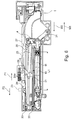
- FIG. 2 shows the exploded view of the device 58, which is designed as an ejector unit 1 for the drawer 53.
- the ejector unit 1 is used for power-assisted ejection of the drawer 53 over a first part of the opening movement of the drawer 53 from a closed position relative to the furniture body 51 in the opening direction M1 of the drawer 53rd
- the drawer 53 is slidably mounted on the furniture body 51 in the direction of M1 and M2 via the guide means 52, for example, two similar partial or full extension.
- the ejector unit 1 may alternatively be arranged on the furniture body 51 or on the guide means 52 of the furniture 50.
- the ejector unit 1 comprises, inter alia, a base plate 2, a force accumulator 3, a coupling device 4, an ejector 5, a trigger element designed as a trigger 6 and a locking member 7.
- a housing of the ejector unit 1 comprises the base plate 2 and a cover component 9, which consists of FIG. 9 is apparent.
- the ejector unit 1 can be arranged via the housing or via the cover component 9 and / or the base plate 2 on the underside of the drawer bottom 54 and / or on the guide means 52.
- the base plate 2 On the base plate 2 holding sections, guide contours, stop members and / or receiving portions for connection of the individual components of the ejector unit 1 are formed.
- the base plate 2 is designed essentially as a rectangular, elongated or strip-shaped component with a comparatively small height h of, for example, approximately 5 to 15 millimeters.
- the base plate 2 further has a width b of about 4 to 10 centimeters and a length g.
- the energy accumulator 3 comprises two parallelly arranged similar spiral springs 10, 11, which form a spring assembly.
- the coil springs 10, 11 are arranged on an adjustable fixed bearing 13.
- the fixed bearing 13 comprises a movable bearing part 14, on which the coil springs 10, 11 are detachably but firmly received and an adjusting member 15 with an operating section 16, via which a user can set a position of the end 12 of the energy accumulator 3 from the outside variable fixed position.
- the associated ends of the coil springs 10, 11 are fixed to a carriage-like moving element 18.
- the slide-like movement element 18 is guided via an associated guide contour 19 on the base plate 2 movable in a direction of movement P1 and an opposite direction of movement P2 linear.
- the directions of movement P1 and P2 of the moving element 18 (see FIG. Figures 2 . 3 ) run parallel to the opening direction M1 of the drawer 53 and a closing direction M2 opposite thereto.
- the ejector unit 1 is fixed in position on the furniture body 51 and / or on a stationary part of the guide means 52 arranged, corresponds to the opening direction of the drawer 53 of the direction P1 and the closing direction of the drawer 53 of the direction P2.
- the Figures 3 . 7 . 8th show the ejector unit 1 in a clamping state of the force accumulator 3, in which the coil springs 10, 11 stretched or stretched claimed, here is the moving member 18 against a retracted in the direction P2 position on the base plate 2 in the direction P1 offset and in one Clamping position held.
- the Figures 5 . 6 show the ejector unit 1 in a discharged basic state of the energy accumulator 3, in which the coil springs 10, 11 are further biased to train, but with a smaller amount, and have a length L1.
- the coil springs 10, 11 In the clamping state of the force accumulator 3, the coil springs 10, 11 have a length L2 which is greater than L1.
- a holding member 32 with a stop element 26 is present on the movement element 18.
- the stop element 26 is in a force-assisted opening operation in contact with an ejector. 5
- the ejector 5 is in particular exclusively linearly movable or parallel to the direction of movement of the moving element 18 in the directions P1 and P2 through a coupling device 4, the force memory 3 and the movement member 18 preferably exclusively during the closing operation of the drawer 53 - and movable.
- a linear guide 20 is formed on the base plate 2, which on guide portions z. B. is tuned on one side of the ejector 5.
- a front gap adjusting arrangement 8, which is formed on the ejector 5, comprises a housing 45 and an adjusting screw 22 with a contact section 21.
- the adjusting screw 22 has an external thread which cooperates with an internal thread on the housing 45.
- a position of the contact section 21 of the adjusting screw 22 in the direction of P1 or P2 is adjustable depending on the direction of rotation.
- the adjusting screw 22 is in particular designed to be self-locking relative to the housing 45.
- driver 23 may for example be present on a fixed rail of the guide means 52 or be attached to the furniture body 51 when the ejector unit 1 is arranged on the drawer 53.
- the ejector unit 1 is arranged on the furniture body 51 or on a positionally fixed part of the guide means 52 of the furniture 50, then the driver 23 on the drawer 53 and be movable to the furniture body 51 be present.
- FIG. 4 shows and is explained in more detail below
- the tensioned or loaded energy storage 3 pulls the moving member 18 in the direction P2, which pushes the ejector 5 in the direction P2 relative to the base plate 2 via the stop member 26 and pushes.
- a pawl component 24 of the ejector unit 1 which is mounted pivotably on the ejector 5, becomes a swiveled-in position that is completely sunk to an outer edge of the base plate 2 FIG. 4 placed in a with a nose partially over the outer edge of the base plate 2 projecting swung-out position ( FIG. 5 ), which is realized via a loop-shaped closed guide track 25 in the base plate 2 and a guide pin 24 a engaging on the pawl component 24.
- the energy storage device 3 In the in FIG. 5 illustrated basic state, the energy storage device 3 is in an end position of the discharge state, the energy storage device 3 can not move the ejector 5 in the direction P2.
- the ejector 5 is then due to the kinetic energy of the drawer 53, which is due to the previous Auswerfterrorism, and / or moved by a manual movement of the drawer 53 in the opening direction M1 by a user in the direction P2 relative to the base plate 2.
- This is possible because the pawl member 24 swung out on the ejector 5 abuts on the driver 23, which in the further drawer movement course of the Ejector 5 reaches its maximum far in the direction P2 on the base plate 2 shifted end position.
- the pawl member 24 is fully pivoted again upon reaching the end position on the ejector 5, which is predetermined by the interaction of the guide track 25 with the guide pin 24 a engaging therein on the pawl component 24.
- the ejector unit 1 separates from the driver 23 and the contact between the driver 23 and the contact portion 21 of the adjusting screw 22 is canceled ( FIG. 6 ).
- the ejector 5 is urged by spring elements 33 on the base plate 2, for example by a few millimeters in the direction of P1.
- the spring elements 33 have compared to the coil springs 10, 11 of the energy accumulator 3, a comparatively small force.
- the bearing pin 31 is arranged at a first end of the clamping lever 30 and can move along a linear guide track 27 and / or a linear guide 63, which is formed on the ejector 5, so long free, in particular within an opening operation of the drawer 53, to the pawl member 24 the bearing pin 31 and / or the clamping lever 30 in direct, play-free contact with the ejector 5 holds.
- the waiting position of the ejector 5, which in FIG. 6 is shown, is also a start position of the ejector 5 for a charging of the energy storage device 3 via the coupling device. 4
- the coupling device 4 comprises in addition to the tensioning lever 30, a guide lever 34 and a connecting element 35.
- the clamping lever 30 is articulated at a second end via a bearing pin 36 on the guide lever 34.
- the connecting element 35 is likewise articulated on the guide lever 34 at a second end via a bearing journal 37 which is at a distance from the bearing journal 36 and at its first end via a further bearing journal 38 on the movement element 18.
- the guide lever 34 is movable at a first end via a bearing pin 39, in particular pivotally arranged on the base plate 2.
- the bearing pin 39 is preferably received both on the base plate 2 and the cover member 9.
- the guide lever 34 of the coupling device 4 comprises at a second end a lever attachment 40.
- a locking element 41 and a stop element 42 are formed on the lever attachment 40.
- the locking element 41 is configured as a spring-loaded pivotable pawl.
- the end position of the discharge state of the energy storage 3 ( FIG. 5 ) is predetermined in particular by a striking of the guide lever 34 on a wall portion 28 of the base plate 2 and / or a striking of the stop member 42 on a wall portion 47 on a web-like wall 48 of the base plate 2.
- the wall portion 47 is formed, for example, from an annular portion of a damping element. Does the stop element 42 of the guide lever 34 after a discharge of the energy storage 3 on the wall portion 47, Due to a remaining bias of the coil springs 10, 11, a tensile force in the direction P2 is transmitted from the moving member 18 via the connecting member 35 to the guide lever 34. Due to the rigid design of the coupling device 4 and the abutment of the stop member 42 on the wall portion 47, the moving member 18 is prevented from further movement in the direction P2, the force storage 3 is held with the moving member 18 without play in the end position of the discharge.
- stop element 42 and / or the wall sections 47, 28 can be designed to be elastic or damping, so that stop noise can be reduced or prevented.
- the guide lever 34 can transmit a force with a translation of the clamping lever 30 on the connecting element 35 during clamping of the energy accumulator 3 due to its configuration.
- the gear ratio is formed on the one hand by the ratio of the distance of the bearing pins 39 and 36 to the distance of the bearing pins 39 and 37 on the guide lever 34, on the other hand by the combined circular and linear movement of the clamping lever 30 and / or the connecting element 35 to each other during the charging of the Force accumulator 4.
- the elements of the coupling device 4 can move as follows due to their arrangement on the ejection unit 1:
- the bearing pin 31 and thus the first end of the clamping lever 30 can move due to its storage in the guide track 27 exclusively parallel to a direction of movement of the ejector 5 in particular parallel to a direction of movement of the movable furniture part 53.
- the bearing pin 38 and thus the first end of the connecting element 35 may be due to its storage on slide-like movement element 18 and thus advantageously in the guide contour 19 exclusively parallel to a direction of movement of the moving member 18 and the ejector 5, in particular move parallel to the direction of movement of the movable furniture part 53.
- the bearing pin 36 and thus the second end of the clamping lever 30 can move due to its storage at the second end of the guide lever 34 exclusively in a circular path about a center of rotation of the bearing pin 39 of the guide lever 34.
- the bearing pin 37 of the connecting element 35 and thus the second end of the connecting element 35 can move due to its storage in a central region of the guide lever 34 exclusively in a circular path about a center of rotation of the bearing pin 39 of the guide lever 34.
- the coupling device 4 can transmit a force for tensioning the energy accumulator 3 from the ejector 5 via the tension lever 30 and the guide lever 34 to the connecting element 35 and thus the energy accumulator 3, in particular the coupling device 4 suppresses the force exerted by the ejector 5 This means that when loading the force accumulator 3, a user has to apply less force to the ejector 5 than he would have to apply if he wanted to load the energy accumulator 3 without a reduction or directly the end 17 of the energy accumulator 3 in would draw direction P1.
- the tensioning of the energy accumulator 3 takes place with a movement of the drawer 53 when closing or on a partial path of the closing movement of the drawer 53.
- the starting position of the ejector unit 1, in which this for tensioning the Force accumulator 3 is prepared and waiting for a closing operation of the drawer shows FIG. 6 ,
- the ejector unit 1 moves towards the driver 23 in the direction of M2.
- the ejector 5 is moved by striking the driver 23 in the direction of P1.
- the ejector 5 At the end of the tensioning process of the energy accumulator 3, the ejector 5 is in a loading end position, this is in FIG. 7 shown. In the clamping state of the energy accumulator 3, the ejector unit 1 is in a locked state.
- the locking element 41 of the coupling device 4 and the locking member 7, which is configured as a flap, determine a locking state, wherein a discharge movement of the coupling device 4 is blocked by the locking member 7.
- the tensioning of the force accumulator 3 is completely completed before, for example, an automatic retraction for force-assisted retraction of the drawer 53 in the fully closed closed position on the furniture body 51 is effective.
- the automatic retraction is not part of the ejector unit 1 and integrated, for example, in the guide means 52 or the partial or full extension.
- the ejector 5 After the tensioning of the energy accumulator 3, the ejector 5 is moved relative to the base plate 2 in the direction P1 due to the engagement on the driver 23 due to the further closing movement of the drawer 53.
- the operative connection between the pawl member 24 of the ejector 5 and the bearing pin 31 of the clamping lever 30 is released. This is done by an interaction of the guide track 25 with the guide pin 24a on the pawl member 24, wherein the pawl member 24 is pivoted away by the guide of the guide pin 24a in the guide track 25 from the bearing pin 31 ( FIG. 8 ).
- the ejector 5 is decoupled from the coupling device 4 and so far moved in the direction P1, in particular by a automatic feed until the drawer 53 is completely closed on the furniture body 51 and the ejector 5 on the trigger 6 in the normal position according to FIG. 3 pending.
- the ejector unit 1 In order to eject the drawer 53 with the ejector unit 1 from the position completely pushed in or closed on the furniture body 51, a user must act on the drawer from the outside in the direction of M2 in an oppressive manner.
- the ejector unit 1 has a so-called touch-latch functionality which knows a locked state which can be unlocked by moving the inserted drawer 53 closed on the furniture body 51 in the closing direction M2.
- This closing movement or the inward pushing of the drawer 53 in the direction of M2 takes place until reaching a stop position corresponding to a front gap, which in the closed state of the drawer 53 in particular by a distance between an inside of the drawer front 55 and a front end or the side walls 56 of the furniture body 51 is predetermined.
- the front gap is usually few Millimeters, for example, about 1 to 10 millimeters.
- the unlocking of the ejector unit 1 is tuned such that a closing movement of the drawer 53 in the direction of M2 of a few millimeters or at most by the amount of the front gap is sufficient to specify the unlocking and thus the power assisted ejection of the drawer 53 safe.
- the ejector unit 1 is moved with the drawer 53 in the direction M2. Since the set screw 22 is present on the driver 23, the ejector 5 is moved relative to the base plate 2 in the direction P1, whereby a contact portion 44 presses on the ejector 5 against the trigger 6 and pushes it in the direction P1 accordingly.
- the trigger 6 is limited linearly in the direction of P1 and P2 slidably provided on the base plate 2, usually by a few millimeters or less than the dimension of the front gap.
- the trigger 6 is preferably coupled directly to the locking member 7, which is designed as a flap 43, such that the linear release movement of the trigger 6 in the direction P1, the flap 43 in a rotational movement about a pivot axis D is added.
- the flap 43 is released from a locking position, in which the flap 43 is urged by a trained as a leaf spring 49 spring member.
- the flap 43 In the locked state of the ejector unit 1, the flap 43, which is in the locking position, blocks the guide lever 34 or the lever cap 40 such that the energy accumulator 3 remains in its charged state.
- the flap 43 With the rotational movement of the flap 43, the blockage of the guide lever 34 is released.
- the prestressed with a leg spring 60 locking element 41 pivots on the lever cap 40 from.
- the lever on the top 40 projecting locking element 41st moves with the pivoting operation of the guide lever 34 below the flap 43 past this and leads initiated by the trigger 6 rotational movement of the flap 43 about the pivot axis D without interruption.
- a rotational angle of the flap 43 is advantageously increased from the locking position.
- the locking element 41 is swung out again by the spring force of the leg spring 60. After the clamping operation, the guide lever 34 is pressed with the protruding locking element 41 against the locking spring 43 held by the leaf spring 49, whereby the energy accumulator 3 is in the locked state.
- the rotational movement of the flap 43 of the ejector unit 1 or the device 58 is transmitted via a synchronous rod 61, which is arranged non-rotatably on the flap 43, on a second advantageous equivalent device 62, which is arranged on the drawer 53.
- the synchronizing rod 61 connects the locking member 7 with a second locking member provided on the second device 62.
- the two Locking organs are thus motion-coupled directly and / or synchronously. This represents a contrary principle of synchronization to a physical connection between triggering elements of two ejector devices on a furniture part.
- FIG. 10 shows in perspective the guide lever 34 with the lever cap 40 and the locking member 41 with the leg spring 60 increases, with an outline of a locking acting part of a wing-like extension 67 of the flap 43 in the locking state or in abutting contact with the locking element 41 according to the state FIG. 3 is indicated.
- the flap 43 forced into the locking state by the leaf spring 49 locks the guide lever 34 against pivotal movement of the guide lever 34 in the direction P3 about the pivot axis S1 of the guide lever 34.
- the guide lever 34 is biased in the direction P3 under the action of the force accumulator 3 in the clamping state ,
- the locking flap 43 forms with a part of a marginal narrow side 65 of the extension 67 a mechanical stop for a narrow end-side section 66 on the locking element 41.
- the section 66 is in FIG. 10 hatched highlighted.
- FIG. 11 shows this condition according to FIG. 3 , If after a triggering operation, the flap 43 is pivoted about the axis D in the direction P4 upwards and thus the locking state is canceled by the flap 43, the narrow side 65 is moved away from the section 66, the guide lever 34 pivots in the direction P3, whereby the force-assisted opening movement the drawer 53 takes place.
- the pivoting of the flap 43 from the locking position in the direction P4 with respect to the relevant part of the narrow side 65 at the portion 66 takes place by a few, for example, 5 to 10 degrees or by the angle gamma or ⁇ , which of the Height h1 of section 66 depends on, for example, about 1 millimeter.
- the height of the narrow side 65 preferably corresponds at least approximately to the height h1.
- the upper side of the locking element 41 acting on the underside against the extension 67 has an obliquely oriented support section 68, so that the flap 43 is raised further in the direction P4 in accordance with the slope of the support section 68.
- the slope of the support portion 68 rises from the portion 66 against the direction P3 to a dome 69 on top of the locking element 41.
- the further lifting of the flap 43 by the locking member 41 is carried by the height h2 according to the height of the support portion 68 and the further pivoting upwards preferably takes place by a pivoting amount in the range of the angle ⁇ or something more.
- the flap 43 is pivoted in particular by at least 2 * ⁇ in the direction P4.
- the pushed back position of the locking element 41 remains through the continuous formation of the web shoulder 70 over the entire subsequent pivoting path of the guide lever 34 in the direction P3 and at later pivoting back of the guide lever 34 in the direction opposite P3 obtained during tensioning of the force accumulator 3 until the locking element 41 passes by the extension 67 and behind again under the action of the leg spring 60 in the locking position according to FIG. 3 or 11 pivots and the guide lever 34 is blocked in the direction P3 by the narrow side 65.
- FIG. 12 refers to the moment of driving or raising the flap 43 on the basis of the locking element 41 shortly after unlocking the locking position of the guide lever 34.
- the outline of the locking element 41 under the extension 67 is indicated by dashed lines.
Abstract
Es wird eine Vorrichtung (1) zum Bewegen eines bewegbaren Möbelteils in eine Öffnungsrichtung des Möbelteils in Bezug zu einem Möbelkorpus eines Möbels vorgeschlagen, wobei das bewegbare Möbelteil über Führungsmittel in die Öffnungsrichtung und in eine Schließrichtung bringbar ist, wobei die Vorrichtung (1) einen Kraftspeicher umfasst, so dass mit der montierten Vorrichtung (1) das bewegbare Möbelteil unter der Wirkung des Kraftspeichers in die Öffnungsrichtung bringbar ist, und wobei die Vorrichtung (1) eine Verriegelungsanordnung zum Verriegeln einer Spannstellung des Kraftspeichers aufweist, in welcher der Kraftspeicher (3) für die Öffnungsbewegung des Möbelteils geladen ist, wobei die Spannstellung entriegelbar ist. Erfindungsgemäß sind ein Verriegelungsorgan (7) der Verriegelungsanordnung und ein bewegbarer, mit dem Kraftspeicher gekoppelter Hebel der Vorrichtung (1) derart zusammenwirkend vorhanden, dass in der verriegelten Spannstellung des Kraftspeichers das Verriegelungsorgan (7) eine Verriegelungsstellung und der Hebel eine Wartestellung einnehmen, in welcher ein Aufheben der Wartestellung des Hebels vom Verriegelungsorgan (7) blockiert ist.A device (1) for moving a movable furniture part in an opening direction of the furniture part in relation to a furniture body of a piece of furniture is proposed, wherein the movable furniture part can be brought via guide means in the opening direction and in a closing direction, wherein the device (1) is a force storage device comprises, so that with the assembled device (1), the movable furniture part under the action of the energy storage device can be brought in the opening direction, and wherein the device (1) has a locking arrangement for locking a clamping position of the energy accumulator, in which the energy storage device (3) for the opening movement of the furniture part is loaded, wherein the clamping position can be unlocked. According to the invention a locking member (7) of the locking arrangement and a movable, coupled to the energy storage lever of the device (1) cooperating such that in the locked clamping position of the energy storage, the locking member (7) occupy a locking position and the lever a waiting position in which a suspension of the waiting position of the lever from the locking member (7) is blocked.
Description
Bei Möbelteilen wie zum Beispiel Schubladen, Möbeltüren oder Möbelklappen, die an einem Möbelkorpus eines Möbels über Führungsmittel bewegbar aufgenommen sind, kommen Vorrichtungen zur Bewegungsbeeinflussung des Möbelteils zum Einsatz. Derartige Vorrichtungen sind z.B. durch eine Einheit gebildet, die an dem Möbelteil, dem Möbelkorpus oder den Führungsmitteln an geeigneter Stelle anbringbar ist.In furniture parts such as drawers, furniture doors or furniture flaps, which are movably received on a furniture body of a furniture via guide means, devices for influencing the movement of the furniture part are used. Such devices are e.g. formed by a unit which is attachable to the furniture part, the furniture body or the guide means at a suitable location.
Die Führungsmittel umfassen insbesondere eine Schiebeführung wie einen Voll- oder Teilauszug oder eine Schwenkführung wie ein Möbelscharnier.The guide means comprise in particular a sliding guide such as a full or partial drawer or a pivoting guide such as a furniture hinge.
Bei modernen und bedienerfreundlichen Möbeln sind beispielsweise Vorrichtungen für die Bewegung des Möbelteils bekannt, die zur Bereitstellung einer Zusatzfunktion wahlweise vorgesehen werden können, insbesondere um einem Nutzer das Öffnen des Möbelteils zu erleichtern. Die Zusatzfunktion ist insbesondere auf die Art und Größe des Möbelteils abstimmbar.In modern and user-friendly furniture devices for the movement of the furniture part are known, for example, which can optionally be provided to provide an additional function, in particular to facilitate a user to open the furniture part. The additional function is particularly tunable to the type and size of the furniture part.
Die Vorrichtung zur Bewegungsbeeinflussung des Möbelteils betrifft z. B. Systeme zur Bereitstellung einer kraftunterstützten Öffnungsfunktion für das Möbelteil.The device for influencing the movement of the furniture part relates z. B. systems for providing a power assisted opening function for the furniture part.
Aufgabe der vorliegenden Erfindung ist es, eine Zusatzfunktion für eine Möbelteilbewegung mittels einer Schiebeführung, wie einem Voll- oder Teilauszug, oder einer Schwenkführung vorteilhaft bereitzustellen, insbesondere um eine funktionssichere Bereitschaftsstellung und Auslösung einer kraftunterstützten Öffnungsbewegung des Möbelteils auf einer ersten Teilstrecke des Öffnungsweges bereitzustellen.The object of the present invention is to advantageously provide an additional function for a furniture part movement by means of a sliding guide, such as a full or partial extension, or a pivoting guide, in particular to provide a functionally reliable standby position and triggering a force-assisted opening movement of the furniture part on a first part of the opening path.
Diese Aufgabe wird durch die unabhängigen Ansprüche gelöst.This object is solved by the independent claims.
In den abhängigen Ansprüchen sind vorteilhafte Varianten der Erfindung aufgezeigt.In the dependent claims advantageous variants of the invention are shown.
Die Erfindung geht aus von einer Vorrichtung zum Bewegung eines bewegbaren Möbelteils in eine Öffnungsrichtung des Möbelteils in Bezug zu einem Möbelkorpus eines Möbels, wobei das bewegbare Möbelteil über Führungsmittel in die Öffnungsrichtung und in eine der Öffnungsrichtung entgegengesetzte Schließrichtung bringbar ist, wobei die Vorrichtung einen Kraftspeicher umfasst, so dass mit der montierten Vorrichtung das bewegbare Möbelteil unter der Wirkung des Kraftspeichers in die Öffnungsrichtung bringbar ist, und wobei die Vorrichtung eine Verriegelungsanordnung zum Verriegeln einer Spannstellung des Kraftspeichers aufweist, in welcher der Kraftspeicher für die Öffnungsbewegung des Möbelteils geladen ist, wobei die Spannstellung entriegelbar ist. Die Erfindung betrifft insbesondere eine Möbelteil-Öffnungsvorrichtung.The invention relates to a device for moving a movable furniture part in an opening direction of the furniture part with respect to a furniture body of a piece of furniture, wherein the movable furniture part can be brought via guide means in the opening direction and in a direction opposite to the opening direction closing direction, wherein the device comprises a force storage device so that with the mounted device, the movable furniture part can be brought under the action of the energy storage in the opening direction, and wherein the device comprises a locking arrangement for locking a clamping position of the energy accumulator, in which the energy storage is loaded for the opening movement of the furniture part, wherein the clamping position is unlockable. The invention particularly relates to a furniture part opening device.
Der Kern der Erfindung liegt darin, dass ein Verriegelungsorgan der Verriegelungsanordnung und ein bewegbarer, mit dem Kraftspeicher gekoppelter Hebel der Vorrichtung derart zusammenwirkend vorhanden sind, dass in der verriegelten Spannstellung des Kraftspeichers das Verriegelungsorgan eine Verriegelungsstellung und der Hebel eine Wartestellung einnehmen, in welcher ein Aufheben der Wartestellung des Hebels vom Verriegelungsorgan blockiert ist. Damit wird vorteilhafterweise eine zuverlässige und funktionsgenau vielfach identisch wiederholbare Verriegelung und Entriegelung gewährleistet. Außerdem ist mit der Erfindung eine geräusch- und reibungsarme Ver- und Entriegelung möglich.The essence of the invention is that a locking member of the locking arrangement and a movable, coupled to the power storage lever of the device are cooperatively present such that in the locked clamping position of the energy storage, the locking member occupy a locking position and the lever a waiting position in which a suspension of the waiting position of the lever is blocked by the locking member. This is advantageously a reliable and functionally many times identically repeatable locking and unlocking guaranteed. In addition, with the invention, a low-noise and low-friction locking and unlocking possible.
Insbesondere ist vorteilhafterweise ein vergleichsweise kurzer Entriegelungsweg des Verriegelungsorgans zum Aufheben der Verriegelung bzw. aus der verriegelnden Stellung heraus in die entriegelte Stellung bereitgestellt. Das Aufheben der Verriegelung erfordert in der Regel eine Aktion von außen durch einen Nutzer z. B. als Auslöse- bzw. Entriegelungsaktion.In particular, a comparatively short unlocking path of the locking member is advantageously provided for releasing the locking or out of the locking position into the unlocked position. The release of the lock usually requires an action from the outside by a user z. B. as a triggering or unlocking action.
Vorzugsweise weist die erfindungsgemäße Vorrichtung zum Auslösen des Entriegelungsvorgangs von außen eine so genannte Touch-Latch-Funktion bzw. eine Touch-Latch-Anordnung auf. Bei integrierter Touch-Latch-Funktion wird das am Möbelkorpus geschlossene und in der Schließstellung in der Regel gehaltene Möbelteil durch eine Bewegung des Möbelteils in Schließrichtung über einen vergleichsweise kurzen Bewegungsweg des Möbelteils bewegt, was den Entriegelungsvorgang beschreibt. Der Entriegelungsvorgang ist Voraussetzung dafür, dass die vom Kraftspeicher kraftunterstützte Öffnungsbewegung des Möbelteils erfolgt.Preferably, the inventive device for triggering the unlocking process from the outside on a so-called touch-latch function or a touch-latch arrangement. With integrated touch-latch function, the furniture body closed and held in the closed position usually furniture part is moved by a movement of the furniture part in the closing direction over a relatively short path of movement of the furniture part, which describes the unlocking process. The unlocking process is a prerequisite for the force-supported by the power storage opening movement of the furniture part.
Das Bewegen des Möbelteils zum Auslösen geschieht durch den Nutzer von außen, der zum Beispiel gegen eine Front des Möbelteils drückt.Moving the furniture part to trigger happens by the user from the outside, for example, pushes against a front of the furniture part.
Beispielsweise wird hierbei ein mit dem Verriegelungsorgan zusammenwirkendes Auslöseelement der Vorrichtung linear bzw. translatorisch bewegt, womit die Verriegelung durch ein Verstellen des Verriegelungsorgans aufhebbar ist. Mit der Erfindung ist der lineare Auslöseweg des Möbelteils und damit des Auslöseelements vorteilhaft auf eine vergleichsweise kurze Auslösestrecke wie zum Beispiel wenige Millimeter reduziert. Die Vorrichtung ist vorteilhaft durch eine hohe Zuverlässigkeit der Verriegelung und der Auslösung ausgezeichnet.For example, a cooperating with the locking member triggering element of the device is thereby moved linearly or translatorily, whereby the locking by a Adjustment of the locking member can be canceled. With the invention, the linear release path of the furniture part and thus the trigger element is advantageously reduced to a relatively short trip distance such as a few millimeters. The device is advantageously distinguished by a high reliability of locking and tripping.
Nach dem Eindrücken des Möbelteils, wenn der Nutzer nicht mehr auf das Möbelteil einwirkt, wobei die Entriegelung abgeschlossen ist, wird unter der Wirkung des geladenen bzw. gespannten Kraftspeichers das Möbelteil aus der am Möbelkorpus geschlossenen Position in die Öffnungsrichtung bewegt. Das Herausbewegen des Möbelteils wie beispielsweise einer Schublade relativ zum Möbelkorpus unter der Kraftspeicherwirkung erfolgt über zumindest eine Teilstrecke eines gemäß der Führungsmittel maximal bereitgestellten Öffnungsweges des Möbelteils am Korpus.After pressing the furniture part, when the user no longer acts on the furniture part, wherein the unlocking is completed, the furniture part is moved from the closed position on the furniture body in the opening direction under the effect of the charged or tensioned energy storage. The moving out of the furniture part such as a drawer relative to the furniture body under the force storage effect via at least a portion of a maximum of the guide means provided opening path of the furniture part on the body.
Die erfindungsgemäße Vorrichtung ist vorzugsweise so gestaltet, dass mit einer Schließbewegung des Möbelteils relativ zum Möbelkorpus der beim Öffnen teilentladene Kraftspeicher wieder geladen wird bzw. wieder in den Spannzustand bringbar ist. Der dazu nötige Kraftaufwand wird vom Nutzer aufgebracht, wenn der Nutzer das Möbelteil in die Schließrichtung drückt. Nach dem Ende des Spannvorgangs mit dem Verriegelungsorgan in der Verriegelungsstellung kann vorteilhaft eine Einzugsautomatik, die z. B. integriert ist in den Führungsmitteln, das Möbelteil um zum Beispiel wenige Zentimeter in die vollständig am Möbelkorpus geschlossene Stellung bringen. Das geschlossene Möbelteil wartet dann auf den nächsten Auslösevorgang.The device according to the invention is preferably designed so that is reloaded with a closing movement of the furniture part relative to the furniture body of the partially discharged during storage power storage is again brought into the clamping state. The force required for this purpose is applied by the user when the user presses the furniture part in the closing direction. After the end of the tensioning operation with the locking member in the locked position can advantageously be an automatic retraction, the z. B. is integrated in the guide means, bring the furniture part to, for example, a few inches in the fully closed to the furniture body position. The closed furniture part then waits for the next release operation.
Der Hebel kann insbesondere ein Koppelelement einer Kopplungseinrichtung sein, welche zwischen dem Kraftspeicher und einem Auswerferbauteil vorhanden ist. Das Auswerferbauteil ist unter der Kraftspeicherwirkung an der Vorrichtung versetzbar, womit das Möbelteil aus der Schließstellung in die Öffnungsrichtung bringbar ist. Die Kopplungseinrichtung ist wirksam, wenn der Nutzer das Möbelteil schließt und dabei das Auswerferbauteil mit Hilfe der Kopplungseinrichtung versetzbar ist, womit der Kraftspeicher in die Spannstellung gebracht wird.The lever may in particular be a coupling element of a coupling device which is present between the energy store and an ejector component. The ejector member is displaceable under the force storage effect on the device, whereby the furniture part from the closed position in the Opening direction can be brought. The coupling device is effective when the user closes the furniture part and while the ejector is displaceable by means of the coupling device, whereby the energy storage is brought into the clamping position.
Der Hebel ist bewegbar an der Vorrichtung vorzugsweise schwenkbar gelagert, wobei der Hebel über den zumindest wesentlichen Entspannvorgang des Kraftspeichers beim Öffnen des Möbelteils eine Bewegung ausführt.The lever is movably mounted on the device preferably pivotally, wherein the lever via the at least substantial relaxation process of the energy store when opening the furniture part performs a movement.
Im Spannzustand des Kraftspeichers befindet sich der verriegelte Hebel in der ruhenden und vom Verriegelungsorgan blockierten Wartestellung. Die Wartestellung beschreibt eine Start-Schwenkposition für den nächsten Öffnungsvorgang. Der Hebel wird in die Richtung blockiert, in welcher der Hebel sich nach der Entriegelung bewegt.In the clamping state of the energy storage is the locked lever in the resting and blocked by the locking member waiting position. The waiting position describes a start swivel position for the next opening process. The lever is locked in the direction in which the lever moves after unlocking.
Die Blockade verhindert demgemäß eine Bewegung des Hebels in eine Entspannrichtung.The blockage accordingly prevents movement of the lever in a relaxation direction.
Damit der verriegelte bzw. blockierte Hebel definiert bzw. dauerhaft für das Öffnen des Möbelteils bereit ist, ist der Hebel unter der Wirkung des geladenen Kraftspeichers vorgespannt in die Entspannrichtung. In diese Richtung bildet das Verriegelungsorgan einen mechanischen Anschlag für den Hebel. Der Hebel ist vorzugsweise derart mit dem Kraftspeicher bewegungsgekoppelt, dass die Position des sich bewegenden bzw. schwenkenden Hebels in eine Schwenkrichtung sich kontinuierlich ändert, wenn sich der Kraftspeicher aus dem Spannzustand mit dem Öffnen des Möbelteils entlädt, und in die andere Schwenkrichtung kontinuierlich zurückschwenkt, wenn der Kraftspeicher wieder gespannt wird.So that the locked or blocked lever is defined or permanently ready for the opening of the furniture part, the lever is biased under the action of the charged energy storage in the relaxation direction. In this direction, the locking member forms a mechanical stop for the lever. The lever is preferably coupled for movement with the force accumulator, that the position of the moving or pivoting lever in a pivoting direction continuously changes when the energy storage discharges from the clamping state with the opening of the furniture part, and continuously pivots back into the other pivoting direction, if the energy storage is stretched again.
Das Verriegelungsorgan ist vorzugsweise so positioniert, dass das Verriegelungsorgan im Verriegelungszustand in den Bewegungsweg des Hebels hineinsteht. Mit dem Aufheben der Verriegelung wird die Blockade des Bewegungswegs des Hebels frei und der Hebel schwenkt am wegbewegten Verriegelungsorgan vorbei.The locking member is preferably positioned so that the locking member is in the locked state in the path of movement of the lever. With the release of the lock becomes the blockage of the movement path of the lever free and the lever pivots past the moving away locking member.
Vorteilhafterweise weist der Hebel einen Kontaktabschnitt auf, welcher in der Wartestellung des Hebels einen blockierten Zustand einnimmt bzw. an dem Verriegelungsorgan in Anlage kommt. Der Kontaktabschnitt ist vorzugsweise verstellbar am Hebel aufgenommen, insbesondere daran reversibel aus einer vorstehenden in eine versenkte Stellung bringbar. Insbesondere ist der Hebel ausschließlich mit dem Kontaktabschnitt mit dem Verriegelungsorgan in Kontakt bringbar. Bevorzugt ist der Kontaktabschnitt am Hebel vorgespannt vorhanden vorzugsweise in Richtung eines am Hebel vorstehenden Zustands vorgespannt. Die Vorspannung ist zum Beispiel mit einer Feder realisiert. Die Feder drängt den Kontaktabschnitt in eine Stellung, in welcher der Kontaktabschnitt und damit der Hebel am Verriegelungsorgan blockiert ist. In der Verriegelungsstellung des Hebels am Verriegelungsorgan ist der Kontaktabschnitt unter der Vorspannung in die Anlagestellung am Verriegelungsorgan gebracht.Advantageously, the lever has a contact portion, which occupies a blocked state in the waiting position of the lever or comes into contact with the locking member. The contact portion is preferably adjustably received on the lever, in particular reversibly from a projecting into a recessed position brought. In particular, the lever can be brought into contact only with the contact portion with the locking member. Preferably, the contact portion is preloaded on the lever present preferably biased in the direction of a lever projecting state. The bias is realized for example with a spring. The spring urges the contact portion into a position in which the contact portion and thus the lever on the locking member is blocked. In the locking position of the lever on the locking member of the contact portion is brought under the bias in the contact position on the locking member.
Der Kontaktabschnitt ist insbesondere an einem Abschnitt des Hebels vorhanden, welcher von einer Lager- bzw. Schwenkachse des Hebels über eine wesentliche Länge des Hebels entfernt ist.In particular, the contact portion is present at a portion of the lever remote from a pivot axis of the lever over a substantial length of the lever.
Der Kontaktabschnitt ist im Verriegelungszustand flächig anliegend am Verriegelungsorgan. Damit ist trotz der sicheren Blockade ein Wegschwenken des Verriegelungsorgans vom Kontaktabschnitt geräuscharm und störungsfrei möglich. Vorzugsweise wird mit der Erfindung ein Verhakungszustand zwischen dem Kontaktabschnitt und dem Verriegelungsorgan vermieden, was gegebenenfalls störanfälliger im Hinblick auf das Einrichten und/oder Lösen des Verriegelungszustands wäre.The contact portion is in the locking state lying flat on the locking member. Thus, despite the safe blockage a pivoting away of the locking member from the contact portion quiet and trouble-free possible. Preferably, a Verhakungszustand between the contact portion and the locking member is avoided with the invention, which would possibly be susceptible to interference with regard to the establishment and / or release of the locking state.
Insbesondere ist es vorteilhaft, dass das Verriegelungsorgan bewegbar gelagert ist, insbesondere schwenkbar. Das Verriegelungsorgan kann vorteilhaft bewegbar bzw. schwenkbar in den Verriegelungszustand und aus diesem heraus gebracht werden. Insbesondere ist nur ein geringer Auslöseweg eines Auslöseelements notwendig, um die Verriegelung mit einem geringen Schwenkweg des Verriegelungsorgans sicher aufzuheben. Vorzugsweise ist das Verriegelungsorgan um eine Achse schwenkbar, die quer zur Schwenkachse des Hebels ausgerichtet ist.In particular, it is advantageous that the locking member is movably mounted, in particular pivotable. The locking member can advantageously be moved or pivoted be brought into the lock state and out of this. In particular, only a small trip path of a trigger element is necessary to safely cancel the lock with a small pivoting of the locking member. Preferably, the locking member is pivotable about an axis which is aligned transversely to the pivot axis of the lever.
Weiter ist es von Vorteil, dass das Verriegelungsorgan vorgespannt ist. Insbesondere ist das Verriegelungsorgan zum entriegeln ausweichbar gegen die Vorspannung. Das Verriegelungsorgan ist in Richtung seiner verriegelnden Stellung bzw. seiner Verriegelungsstellung vorgespannt. Vorteilhafterweise ist auf diese Weise die Verriegelungsposition unter der Wirkung der Vorspannung sicher einrichtbar und gesteuert wieder aufhebbar. Nach dem Aufheben der Verriegelung gelangt das Verriegelungsorgan selbsttätig unter der Vorspannung in die Verriegelungsposition zurück, wenn keine die Vorspannung aufhebende Gegenkraft wirksam ist.Further, it is advantageous that the locking member is biased. In particular, the locking member for unlocking evades the bias. The locking member is biased in the direction of its locking position and its locking position. Advantageously, in this way the locking position under the action of the bias safely set up and controlled canceled again. After releasing the lock, the locking member automatically returns under the bias in the locking position when no counteracting force canceling counteracting force is effective.
Beim Entriegeln wird das Verriegelungsorgan gegen die Wirkung der Vorspannung ausgelenkt, wofür eine Aufhebungskraft von außen notwendig ist. Diese Kraft wird beim Auslösen vom Nutzer aufgebracht. Sobald der Nutzer ablässt, wird das Verriegelungsorgan wieder in die Verriegelungsstellung gedrängt. Als Vorspannelement für das Verriegelungsorgan kommt beispielsweise eine Feder vorzugsweise eine Blattfeder in Frage.When unlocking the locking member is deflected against the action of the bias, for which a Aufhebungskraft from the outside is necessary. This force is applied when triggered by the user. Once the user releases, the locking member is pushed back into the locking position. As a biasing element for the locking member, for example, a spring is preferably a leaf spring in question.
Es ist überdies vorteilhaft, dass der Kontaktabschnitt aus dem blockierten Zustand ausweichbar gelagert ist. Mit dem Ausweichen relativ zum Hebel kann insbesondere das Spannen des Kraftspeichers vorteilhaft erfolgen. Vorteilhaft wird mit dem Entspannen der Kontaktabschnitt versetzt und beibehalten bis zum Ende des Spannvorgangs, dass dafür keine Kraft beim Spannen aufgebracht werden muss, was für den Spannvorgang vorteilhaft ist, da beim Spannen ohnehin eine vergleichsweise große Kraft vom Nutzer aufzubringen ist bzw. damit keine weitere Kraft für das Zurückdrängen des Kontaktabschnitts notwendig ist.It is also advantageous that the contact portion is mounted deflected from the blocked state. By dodging relative to the lever in particular the tensioning of the energy storage can be advantageous. It is advantageous to offset the relaxation of the contact portion and maintained until the end of the clamping process, that for no force during clamping must be applied, which is advantageous for the clamping operation, since when clamping a comparatively large force is applied by the user anyway or so further force is necessary for pushing back the contact section.
Vorzugsweise ist der Kontaktabschnitt federbeaufschlagt, beispielsweise mit einer Schenkelfeder.Preferably, the contact portion is spring loaded, for example with a leg spring.
Insbesondere ist es vorteilhaft, dass beim Einrichten der Verriegelung das Verriegelungsorgan in seiner verriegelnden Stellung verbleiben kann, womit in der vergleichsweise kritischen Phase im Moment der Einrichtung der Verriegelung eine Funktionsstörung aufgrund einer Bewegung des Verriegelungsorgans ausgeschlossen bzw. minimiert ist. Denn das Verriegelungsorgan braucht nicht verstellt werden, da es sich bereits in der Verriegelungsstellung befindet. Nur beim Auslösevorgang wird das Verriegelungsorgan kurzzeitig aus dem Verriegelungszustand herausbewegt und unmittelbar danach wieder in den Verriegelungszustand zurückgebracht. Damit verbleibt das Verriegelungsorgan selbst am Ende des Spannvorgangs in der Verriegelungsstellung und muss diese nicht verlassen, damit der Kontaktabschnitt daran vorbeikommt, um in die blockierte Stellung zu gelangen. Gemäß der Erfindung weicht vielmehr der Kontaktabschnitt aus dem blockierten Zustand aus und gelangt nach dem Passieren am ruhenden Verriegelungsorgan vorbei vorgespannt in die blockierte Stellung.In particular, it is advantageous that when setting the lock, the locking member may remain in its locking position, which in the comparatively critical phase at the moment of the establishment of the locking a malfunction due to a movement of the locking member is excluded or minimized. Because the locking member does not need to be adjusted because it is already in the locked position. Only when the triggering operation, the locking member is briefly moved out of the locking state and immediately returned to the locking state. Thus, the locking member remains even at the end of the clamping operation in the locked position and must not leave this, so that the contact section passes it to get into the blocked position. Rather, according to the invention, the contact section deviates from the blocked state and, after passing through the stationary locking element, passes prestressed into the blocked position.
Das Rückstellen des vergleichsweise kleinen und leichten Kontaktabschnitts in den blockierten Zustand ist dabei unkritisch.The return of the comparatively small and light contact portion in the blocked state is not critical.
Der Kontaktabschnitt weicht beim Spannvorgang des Kraftspeichers am Verriegelungsorgan in eine am Hebel nicht bzw. weniger weit vorstehende Stellung aus, was lediglich kurz vor Erreichen des Verriegelungszustands geschieht, womit der Hebel am Verriegelungsorgan vorbeikommt. Nach dem Passieren am Verriegelungsorgan vorbei gelangt der Kontaktabschnitt sofort wieder durch die Vorspannung selbsttätig und sicher in den blockierten Zustand und ist am Verriegelungsorgan blockiert.The contact portion deviates during the clamping operation of the force accumulator on the locking member in a lever on the not or less projecting position, which happens only shortly before reaching the locking state, whereby the lever passes the locking member. After passing the locking member passing the contact section immediately returns automatically by the bias and safely in the locked state and is blocked on the locking member.
Dies erfolgt drucklos, da mit dem Schwung am Ende des Spannvorgangs der Hebel etwas weiter in Spannrichtung an dem Verriegelungsorgan vorbeischwenkt und damit der Kontaktabschnitt sicher in die vorstehende Stellung gelangen kann, bevor der Hebel nach Ablassen der Spannkraft mit dem vorstehenden Kontaktabschnitt gegen das Verriegelungsorgan anschlägt und blockiert ist.This is done without pressure, since with the momentum at the end of the clamping operation, the lever swings a little further in the clamping direction of the locking member and thus the contact portion can safely reach the protruding position before the lever abuts after releasing the clamping force with the projecting contact portion against the locking member and is blocked.
Der Kontaktabschnitt ist demgemäß in die Richtung des blockierten Zustands vorgespannt bzw. in eine ausgeschwenkte Stellung vorgespannt, bezogen auf den Hebel.The contact portion is accordingly biased in the direction of the locked state or biased in a swung-out position with respect to the lever.
Eine vorteilhafte Modifikation der Erfindung zeichnet sich dadurch aus, dass der Kontaktabschnitt an einer schwenkbaren Klinke ausgestaltet ist. Dies ist ein besonders kompaktes und zuverlässiges Konstruktionsprinzip. Die Klinke ist gegen eine Federwirkung einschwenkbar. Der Kontaktabschnitt ist bevorzugt flächig ausgestaltet z. B. durch einen Bauteilrand gebildet.An advantageous modification of the invention is characterized in that the contact section is designed on a pivotable pawl. This is a particularly compact and reliable design principle. The pawl can be pivoted in against a spring effect. The contact portion is preferably designed flat z. B. formed by a component edge.
Nach einer vorteilhaften Variante der Erfindung sind das Verriegelungsorgan und der Hebel derart abgestimmt, dass ein Verlassen der Verriegelungsstellung des Verriegelungsorgans Voraussetzung dafür ist, dass die Wartestellung des Hebels aufhebbar ist. Für das Verlassen der Verriegelungsstellung genügt vorteilhaft bereits eine geringfügige Bewegung des Verriegelungsorgans aus der ruhenden Verriegelungsstellung heraus. Die geringfügige Bewegung kann insbesondere eine geringe Schwenkbewegung um wenige Winkelgrade um die Schwenkachse des Verriegelungsorgans sein. Mit der Bewegung ist die Blockade des Hebels aufgehoben. Wenn der Hebel bzw. der Kontaktabschnitt am Verriegelungsorgan außer Kontakt gelangt, stellt sich das Verriegelungsorgan in die verriegelnde Stellung zurück.According to an advantageous variant of the invention, the locking member and the lever are tuned such that leaving the locking position of the locking member is a prerequisite that the waiting position of the lever can be canceled. For leaving the locking position advantageously already sufficient a slight movement of the locking member out of the dormant locking position. The slight movement may in particular be a small pivoting movement by a few angular degrees about the pivot axis of the locking member. With movement blockage of the lever is suspended. When the lever or the contact portion on the locking member comes out of contact, the locking member is returned to the locking position.
Es ist darüber hinaus vorteilhaft, dass das Verriegelungsorgan und ein Stützabschnitt am Hebel derart abgestimmt sind, dass mit dem Verlassen der Verriegelungsstellung des Verriegelungsorgans der Stützabschnitt auf das Verriegelungsorgan wirkt, wobei sich das Verriegelungsorgan von der Verriegelungsstellung wegbewegt. Beim Auslösen wird das Verriegelungsorgan durch den Stützabschnitt vorteilhaft um einen zusätzlichen Bewegungsweg weiterbewegt in die Richtung, welche das Verriegelungsorgan weiter von der Verriegelungsstellung entfernt.It is also advantageous that the locking member and a support portion are tuned to the lever such that when leaving the locking position of the locking member of the support portion on the Locking member acts, wherein the locking member moves away from the locking position. When triggered, the locking member is advantageously advanced by the support portion an additional path of movement in the direction which further removes the locking member from the locking position.
Insbesondere wird das Verriegelungsorgan mit dem Verlassen der Verriegelungsstellung ohne Richtungsänderung vom Stützabschnitt um den zusätzlichen Bewegungsweg bzw. um weitere Winkelgrade aus der Verriegelungsstellung wegbewegt bzw. weggeschwenkt.In particular, the locking member is moved away or pivoted away from the support portion to the additional movement path or by further degrees from the locking position with the leaving the locking position without change of direction.
Das Weiterbewegen des Verriegelungsorgans erfolgt insbesondere mit der Hebelbewegung beim Entspannen des Kraftspeichers nach dem Entriegeln. Der verlagerbare Stützabschnitt am Hebel kann relativ zum Hebel bewegbar sein oder nicht.The further movement of the locking member takes place in particular with the lever movement when relaxing the force accumulator after unlocking. The displaceable support portion on the lever may or may not be movable relative to the lever.
Auch ist es vorteilhaft, dass der Kontaktabschnitt und der Stützabschnitt am Hebel an einem gemeinsamen Bauteil ausgestaltet sind. Dies ist insbesondere eine schwenkbare Klinke an einem Hebel wie zum Beispiel einem Führungshebel bzw. an einem Hebelaufsatz eines Führungshebels. Mit dem Stützabschnitt, der unmittelbar nach der zur Entriegelung des Verriegelungsorgans notwendigen Bewegung des Verriegelungsorgans wirksam wird, wird die Bewegung des Verriegelungsorgans insbesondere um einen vorgebbaren Bewegungsweg vorzugsweise zwangsgesteuert vergrößert.It is also advantageous that the contact portion and the support portion are configured on the lever on a common component. This is in particular a pivotable pawl on a lever such as a guide lever or on a lever attachment of a guide lever. With the support portion which is effective immediately after the necessary to unlock the locking member movement of the locking member, the movement of the locking member is preferably forcibly increased by a predetermined movement path positively controlled.
Die Bewegungserweiterung ist im Hinblick auf eine Bewegungsübertragung von dem Verriegelungsorgan auf ein anderes Element wie z. B. ein Element einer Funktionseinheit vorteilhaft. Die Funktionseinheit ist eine zur Vorrichtung separate Einheit und zu dieser beabstandet vorhanden. Häufig ist es notwendig, dass eine synchrone und vollständige Übertragung der Bewegung des Verriegelungsorgans, insbesondere bezogen auf den Entriegelungsvorgang, auf das Element der Funktionseinheit übertragen wird. Hierzu muss sichergestellt sein, dass die Bewegung des Verriegelungsorgans gegenüber der notwendigen Bewegung des Verriegelungsorgans, die für eine Entriegelung ausreicht, vergrößert ist. Denn mit der Bewegungsübertragung über z. B. ein Verbindungselement geht ein Verlustanteil der Bewegung auf dem Übertragungsweg verloren. Die Bewegungsübertragung ist vorzugsweise mit dem zwischen dem Verriegelungsorgan und dem Element körperlich verbindenden Verbindungselement realisiert.The movement extension is with regard to a transmission of movement from the locking member to another element such. B. an element of a functional unit advantageous. The functional unit is a device separate from the device and spaced therefrom. Often it is necessary that a synchronous and complete transmission of the movement of the locking member, in particular with respect to the unlocking process, is transferred to the element of the functional unit. This must be ensured be that the movement of the locking member relative to the necessary movement of the locking member, which is sufficient for unlocking, is increased. Because with the motion transmission over z. As a connecting element is lost a loss of movement on the transmission lost. The transmission of movement is preferably realized with the connecting element which connects physically between the locking member and the element.
Damit eine Bewegung am Element der Funktionseinheit in dem Maß ankommt, welches für das Element erforderlich ist, muss der Verlustanteil auf dem Verbindungsweg mit dem Verbindungselement berücksichtigt werden. Der Verlustanteil ist begründet durch Materialeigenschaften und/oder Bauteiltoleranzen. Daher muss die Bewegung des Verriegelungsorgans beim Entriegelungsvorgang vergrößert werden, so dass dies vergrößert Bewegung vom Verbindungselement aufgenommen werden kann und an das Element der Funktionseinheit übertragbar ist. Dort kommt dann eine Bewegung an, die ausreichend ist bzw. zumindest dem Maß der Bewegung des Verriegelungsorgans entspricht, die dieses ohne Vergrößerung mit dem Stützabschnitt ausführt.For a movement to arrive at the element of the functional unit to the extent that is required for the element, the loss share must be taken into account on the connection path with the connecting element. The loss share is due to material properties and / or component tolerances. Therefore, the movement of the locking member during the unlocking process must be increased, so that this increased movement can be absorbed by the connecting element and is transferable to the element of the functional unit. There then comes to a movement that is sufficient or at least equal to the degree of movement of the locking member that executes this without enlargement with the support portion.
Eine vorteilhafte Variante der Erfindung ist dadurch gekennzeichnet, dass das Verriegelungsorgan und der Hebel aufeinander abgestimmt sind, so dass der Hebel bei einem Spannen des Kraftspeichers an dem Verriegelungsorgan vorbeibewegbar ist, wobei der Hebel in die Wartestellung bringbar ist. Damit kann vorteilhafterweise die Verriegelungsstellung unmittelbar und sicher eingerichtet werden. Insbesondere weicht der Kontaktabschnitt beim Spannen bzw. ggf. die Klinke durch Anlage am Verriegelungsorgan am Hebel zurück. Durch die Vorspannung der Klinke gelangt diese selbsttätig in die vorstehende Position am Hebel wieder zurück, sobald der Hebel am Verriegelungsorgan vorbeibewegt ist. Damit wird der Kontaktabschnitt in der Wartestellung des Hebels am Verriegelungsorgan in Anlage gebracht. Der Hebel ist damit in der Wirkung des gespannten Kraftspeichers durch das Verriegelungsorgan daran anliegend in die entsprechende Entriegelungsrichtung blockiert.An advantageous variant of the invention is characterized in that the locking member and the lever are matched to each other, so that the lever can be moved past the locking member during a tensioning of the force accumulator, wherein the lever can be brought into the waiting position. Thus, advantageously, the locking position can be set up immediately and safely. In particular, the contact portion during clamping or possibly the pawl gives way by resting on the locking member on the lever. Due to the bias of the pawl, this automatically returns to the protruding position on the lever as soon as the lever is moved past the locking member. Thus, the contact portion in the waiting position of the lever on the locking member is brought into abutment. The lever is thus in the action of the tensioned energy storage by the Locking member adjacent thereto blocked in the corresponding unlocking direction.
Die Erfindung betrifft außerdem ein Möbel mit einem Möbelkorpus und einem bewegbaren Möbelteil, das über Führungsmittel in eine Öffnungsrichtung des Möbelteils und in eine der Öffnungsrichtung entgegengesetzte Schließrichtung relativ zu dem Möbelkorpus bringbar ist, wobei eine Vorrichtung wie oben erläutert vorgesehen ist. Damit können an einem Möbel, insbesondere an einem Möbel mit einer Schublade oder einer Klappe oder Tür die oben genannten Vorteile eingerichtet werden. Insbesondere ist dies bei Möbel vorteilhaft, welche in einer Führung bzw. einem Vollauszug eine Einzugsautomatik aufweisen, mit welcher das Möbelteil in die vollständig geschlossene Schließposition am Möbel einziehbar ist.The invention also relates to a piece of furniture with a furniture body and a movable furniture part, which can be brought via guide means in an opening direction of the furniture part and in a direction opposite to the opening direction opposite closing direction relative to the furniture body, wherein a device is provided as explained above. Thus, the above advantages can be set to a piece of furniture, especially on a piece of furniture with a drawer or a flap or door. In particular, this is advantageous in furniture, which have in a guide or a full extension automatic feed with which the furniture part in the fully closed position on the furniture is retractable.
Insbesondere weist das Möbel außerdem eine Vorrichtung wie erläutert und eine Zwillings-Vorrichtung auf, wobei eine Touch-Latch-Funktion in beiden Vorrichtungen durch eine Synchronisation synchronisiert ist. Beispielsweise kann damit eine sichere Auslösung der Verriegelungsstellung des Verriegelungsorgans eingerichtet werden, unabhängig davon, wo die Kraft auf das Möbelteil aufgebracht wird. Beispielsweise wenn eine erfindungsgemäße Vorrichtung im Bereich von rechtsseitig am Möbelteil montierten Führungsmittel und eine Zwillings-Vorrichtung im Bereich von linksseitig am Möbelteil montierten Führungsmittel vorhanden sind, kann bei einem Einwirken durch den Nutzer auf das Möbelteil nahe der rechtsseitigen Vorrichtung das Verriegelungsorgan der rechten Vorrichtung sicher auslösen. Mit der Synchronisation wird dann auch sicher und synchron das Verriegelungsorgan der linksseitigen Zwillings-Vorrichtung ausgelöst bzw. entriegelt.In particular, the furniture also comprises a device as explained and a twin device, wherein a touch-latch function is synchronized in both devices by a synchronization. For example, thus a safe release of the locking position of the locking member can be set up, regardless of where the force is applied to the furniture part. For example, if a device according to the invention in the range of right side mounted on the furniture part guide means and a twin device in the range of left side mounted on the furniture part guide means are present, the locking member of the right device can safely trigger when acted upon by the user on the furniture part near the right-side device , With the synchronization, the locking member of the left-side twin device is then safely and synchronously triggered or unlocked.
Weitere Merkmale und Vorteile der Erfindung sind anhand von in den Figuren schematisiert dargestellten Ausführungsbeispielen der Erfindung näher erläutert.Further features and advantages of the invention are based on exemplary embodiments illustrated schematically in the figures the invention explained in more detail.
Im Einzelnen zeigt:
Figur 1- ein erfindungsgemäßes Möbel perspektivisch von schräg oben mit einer Schublade im vollständig geöffneten Zustand an einem Möbelkorpus,
Figur 2- eine erfindungsgemäße Vorrichtung ohne ein Abdeckbauteil in Explosionsdarstellung,
Figur 3bis Figur 8- die
Vorrichtung gemäß Figur 2 im zusammengesetzten Zustand in einer Aufsicht einer ersten Hauptseite in unterschiedlichen Betriebszuständen, Figur 9- die
Vorrichtung gemäß Figur 5 mit einem Abdeckbauteil perspektivisch schräg von unten mit Blick auf eine zweite Hauptseite der Vorrichtung, Figur 10- perspektivisch und vergrößert einen Führungshebel im
Zustand gemäß Figur 3 , wobei ein Umriss eines Teils eines Verriegelungsorgans gestrichelt angedeutet ist, Figur 11- einen vergrößerten Ausschnitt gemäß dem Bereich
K1 aus Figur 3 und Figur 12- einen vergrößerten Ausschnitt gemäß dem Bereich
K2 aus Figur 4 .
- FIG. 1
- an inventive furniture in perspective from obliquely above with a drawer in the fully open state on a furniture body,
- FIG. 2
- a device according to the invention without a cover component in exploded view,
- FIG. 3 to FIG. 8
- the device according to
FIG. 2 in the assembled state in a plan view of a first main page in different operating states, - FIG. 9
- the device according to
FIG. 5 with a cover component in perspective obliquely from below with a view of a second main side of the device, - FIG. 10
- in perspective and increases a guide lever in the state according to
FIG. 3 wherein an outline of a part of a locking member is indicated by dashed lines, - FIG. 11
- an enlarged section according to the area K1
FIG. 3 and - FIG. 12
- an enlarged section according to the area K2
FIG. 4 ,
Ein erfindungsgemäßes Möbel 50 mit einem kastenförmigen Möbelkorpus 51 und einer über Führungsmittel 52 beweglich geführten Schublade 53 ist in
Die Auswerfereinheit 1 dient zum kraftunterstützten Auswerfen der Schublade 53 über eine erste Teilstrecke der Öffnungsbewegung der Schublade 53 aus einer geschlossenen Stellung relativ zum Möbelkorpus 51 in die Öffnungsrichtung M1 der Schublade 53.The
Die Schublade 53 ist über die Führungsmittel 52, beispielsweise zwei gleichartige Teil- oder Vollauszüge, am Möbelkorpus 51 in Richtung M1 und M2 verschiebbar gelagert. Die Auswerfereinheit 1 kann alternativ am Möbelkorpus 51 oder an den Führungsmitteln 52 des Möbels 50 angeordnet sein.The
Die Auswerfereinheit 1 umfasst unter anderem eine Grundplatte 2, einen Kraftspeicher 3, eine Kopplungseinrichtung 4, einen Auswerfer 5, ein als Auslöser 6 ausgebildetes Auslöseelement und ein Verriegelungsorgan 7.The
Ein Gehäuse der Auswerfereinheit 1 umfasst die Grundplatte 2 und ein Abdeckbauteil 9, welches aus
An der Grundplatte 2 sind Halteabschnitte, Führungskonturen, Anschlagsorgane und/oder Aufnahmeabschnitte zur Anbindung der einzelnen Komponenten der Auswerfereinheit 1 ausgebildet. Die Grundplatte 2 ist im Wesentlichen als rechteckiges, längliches bzw. streifenförmiges Bauteil mit einer vergleichsweise geringen Höhe h von zum Beispiel zirka 5 bis 15 Millimeter ausgestaltet. Die Grundplatte 2 weist des Weiteren eine Breite b von zirka 4 bis 10 Zentimeter und eine Länge g auf.On the
Der Kraftspeicher 3 umfasst gemäß des gezeigten Ausführungsbeispiels zwei parallel angeordnete gleichartige Spiralfedern 10, 11, die ein Federpaket ausbilden. An einem ersten Ende 12 des Kraftspeichers 3 sind die Spiralfedern 10, 11 an einem einstellbaren Festlager 13 angeordnet. Das Festlager 13 umfasst ein bewegbares Lagerteil 14, an welchem die Spiralfedern 10, 11 lösbar aber fest aufgenommen sind und ein Stellteil 15 mit einem Bedienabschnitt 16, über welchen ein Nutzer von außen eine Position des Endes 12 des Kraftspeichers 3 veränderlich positionsfest einstellen kann. Hierdurch kann vorteilhaft eine Kraftwirkung des Kraftspeichers 3 auf die Schublade 53 beim Öffnungsvorgang der Schublade 53 voreingestellt werden.According to the embodiment shown, the
An einem zweiten Ende 17 des Kraftspeichers 3 sind die dazugehörigen Enden der Spiralfedern 10, 11 an einem schlittenartigen Bewegungselement 18 befestigt. Das schlittenartige Bewegungselement 18 ist über eine dazugehörige Führungskontur 19 an der Grundplatte 2 beweglich in eine Bewegungsrichtung P1 und eine entgegengesetzte Bewegungsrichtung P2 linear geführt.At a
Die Bewegungsrichtungen P1 und P2 des Bewegungselements 18 (s.
Ist die Auswerfereinheit 1 positionsfest am Möbelkorpus 51 und/oder an einem stationären Teil der Führungsmittel 52 angeordnet, entspricht die Öffnungsrichtung der Schublade 53 der Richtung P1 und die Schließrichtung der Schublade 53 der Richtung P2.If the
Im Weiteren wird von einem Montagezustand der Auswerfereinheit 1 am Schubladenboden 54 ausgegangen.In addition, it is assumed that a mounting state of the
Die
Die
The
Im Spannzustand des Kraftspeichers 3 weisen die Spiralfedern 10, 11 eine Länge L2 auf, welche größer als L1 ist.In the clamping state of the
Am Bewegungselement 18 ist ein Halteorgan 32 mit einem Anschlagselement 26 vorhanden. Das Anschlagselement 26 ist bei einem kraftunterstützten Öffnungsvorgang in Kontakt mit einem Auswerfer 5.On the
Über eine Kopplungseinrichtung 4 steht der Kraftspeicher 3 bzw. das Bewegungselement 18 vorzugsweise ausschließlich beim Schließvorgang der Schublade 53 in Wirkverbindung mit dem Auswerfer 5. Der Auswerfer 5 ist insbesondere ausschließlich linear bewegbar bzw. parallel zur Bewegungsrichtung des Bewegungselements 18 in die Richtungen P1 und P2 hin- und her bewegbar. Hierfür ist eine Linearführung 20 an der Grundplatte 2 ausgebildet, welche auf Führungsabschnitte z. B. auf einer Seite des Auswerfers 5 abgestimmt ist.The
Ein von der Auswerfereinheit 1 bewirkter Öffnungsvorgang der Schublade 53 findet ausschließlich über eine direkte Wirkverbindung des Kraftspeichers 3 über das sich in Richtung P2 bewegende Bewegungselement 18 auf den Auswerfer 5 statt. Hierfür ist am Bewegungselement 18 ein Anschlagselement 26 ausgebildet, welches vorteilhaft elastisch ausgestaltet ist und damit ein für einen Nutzer störendes Geräusch beim Auftreffen des Bewegungselements 18 auf den Auswerfer 5 im Öffnungsvorgang der Schublade 53 verhindert oder zumindest dämpft (
Eine Frontspalt-Einstellanordnung 8, welche am Auswerfer 5 ausgebildet ist, umfasst ein Gehäuse 45 und eine Stellschraube 22 mit einem Kontaktabschnitt 21. Die Stellschraube 22 weist ein Außengewinde auf, welches mit einem Innengewinde am Gehäuse 45 zusammenwirkt. Durch manuelles Drehen eines Bedienabschnitts 46 der Stellschraube 22 durch einen Nutzer ist abhängig von der Drehrichtung eine Position des Kontaktabschnitts 21 der Stellschraube 22 in Richtung P1 oder P2 verstellbar. Die Stellschraube 22 ist insbesondere selbsthemmend relativ zum Gehäuse 45 ausgebildet. Durch die Positionsvorgabe der Stellschraube 22 ist ein Maß eines Frontspalts zwischen der Schubladenfront 55 der am Möbelkorpus 51 geschlossenen Schublade 53 und Stirnseiten des Möbelkorpus 51 vorgebbar.A front
Der Kontaktabschnitt 21 der Stellschraube 22 steht im gespannten bzw. geladenen Zustand des Kraftspeichers 3 an einem Mitnehmer 23 an, welcher in entsprechenden Betriebszuständen einen Anschlag für den Kontaktabschnitt 21 bildet. Der in den
Ist die Auswerfereinheit 1 hingegen am Möbelkorpus 51 oder an einem positionsfesten Teil der Führungsmittel 52 des Möbels 50 angeordnet, so kann der Mitnehmer 23 an der Schublade 53 und damit beweglich zum Möbelkorpus 51 vorhanden sein.If, however, the
Wird ausgehend von der Grundstellung der Auswerfereinheit 1 gemäß
Sobald sich der Auswerfer 5 an der Grundplatte 2 in Richtung P2 bewegt, wird ein schwenkbar am Auswerfer 5 gelagertes Klinkenbauteil 24 der Auswerfereinheit 1 aus einer zu einem Außenrand der Grundplatte 2 vollständig versenkten Einschwenkstellung gemäß
Zur Darstellung des Klinkenbauteils 24 ist dessen durch andere Bauteile, insbesondere durch den Auswerfer 5 verdeckter Umriss in den
In dem in
Der Auswerfer 5 wird anschließend aufgrund der Bewegungsenergie der Schublade 53, was bedingt durch die vorausgegangene Auswerfbewegung ist, und/oder durch ein manuelles Weiterbewegen der Schublade 53 in Öffnungsrichtung M1 durch einen Nutzer, in Richtung P2 relativ zur Grundplatte 2 verschoben. Dies ist deshalb möglich, weil das am Auswerfer 5 vorstehend herausgeschwenkte Klinkenbauteil 24 am Mitnehmer 23 anstößt, womit im weiteren Schubladen-Bewegungsverlauf der Auswerfer 5 seine maximal weit in Richtung P2 an der Grundplatte 2 verschobene Endstellung erreicht. Das Klinkenbauteil 24 wird mit Erreichen der Endstellung am Auswerfer 5 wieder vollkommen eingeschwenkt, was durch das Zusammenspiel der Führungsbahn 25 mit dem darin eingreifenden Führungszapfen 24a am Klinkenbauteil 24 vorgegeben ist.The
Wird die Schublade 53 nach einem Entladevorgang des Kraftspeichers 3 weiter in Öffnungsrichtung M1 bewegt, trennt sich die Auswerfereinheit 1 vom Mitnehmer 23 und der Kontakt zwischen dem Mitnehmer 23 und dem Kontaktabschnitt 21 der Stellschraube 22 wird aufgehoben (
Aus der oben beschriebenen Endstellung, die der Auswerfer nur kurzzeitig einnimmt, wird der Auswerfer 5 durch Federelemente 33 an der Grundplatte 2 zum Beispiel um wenige Millimeter in Richtung P1 gedrängt. Die Federelemente 33 besitzen gegenüber den Spiralfedern 10, 11 des Kraftspeichers 3 eine vergleichsweise geringe Kraft. Mit der Bewegung des Auswerfers 5 in Richtung P1 durch die Kraft der Federelemente 33 wird ein Anlageabschnitt 29 des Klinkenbauteils 24 in einer Warteposition des Auswerfers 5 in direkten, spielfreien Kontakt mit einem Lagerzapfen 31 eines Spannhebels 30 der Kopplungseinrichtung 4 gebracht (
Die Warteposition des Auswerfers 5, welche in
Die Kopplungseinrichtung 4 umfasst neben dem Spannhebel 30, einen Führungshebel 34 und ein Verbindungselement 35. Der Spannhebel 30 ist an einem zweiten Ende über einen Lagerzapfen 36 am Führungshebel 34 angelenkt. Das Verbindungselement 35 ist an einem zweiten Ende über einen zum Lagerzapfen 36 beabstandeten Lagerzapfen 37 ebenfalls am Führungshebel 34 und an seinem ersten Ende über einen weiteren Lagerzapfen 38 am Bewegungselement 18 angelenkt. Der Führungshebel 34 ist an einem ersten Ende über einen Lagerzapfen 39 bewegbar, insbesondere schwenkbar an der Grundplatte 2 angeordnet. Der Lagerzapfen 39 ist vorzugsweise sowohl an der Grundplatte 2 als auch am Abdeckbauteil 9 aufgenommen.The
Eine Längsachse A1 des Spannhebels 30, welche durch die Lagerzapfen 31, 36 des Spannhebels 30 verläuft, weist zu einer ersten Längsachse A2 des Führungshebels 34, welche durch die Lagerzapfen 36, 39 verläuft, einen Winkel α auf.A longitudinal axis A1 of the clamping
Eine Längsachse A3 des Verbindungselements 35, welche durch die Lagerzapfen 37, 38 des Verbindungselements 35 verläuft, weist zu einer zweiten Längsachse A4 des Führungshebels 34, welche durch die Lagerzapfen 37, 39 verläuft, einen Winkel β auf.A longitudinal axis A3 of the connecting
Der Führungshebel 34 der Kopplungseinrichtung 4 umfasst an einem zweiten Ende einen Hebelaufsatz 40. Am Hebelaufsatz 40 sind ein Verriegelungselement 41 und ein Anschlagselement 42 ausgebildet. Das Verriegelungselement 41 ist als federbeaufschlagte schwenkbare Klinke ausgestaltet.The
Die Endstellung des Entladezustands des Kraftspeichers 3 (
Insbesondere das Anschlagselement 42 und/oder die Wandabschnitte 47, 28 können elastisch bzw. dämpfend ausgestaltet sein, womit Anschlagsgeräusch verringert oder verhindert werden.In particular, the
Der Führungshebel 34 kann beim Spannen des Kraftspeichers 3 aufgrund seiner Ausgestaltung eine Kraft mit einer Übersetzung vom Spannhebel 30 auf das Verbindungselement 35 übertragen.The
Das Übersetzungsverhältnis wird zum einen durch das Verhältnis des Abstands der Lagerzapfen 39 und 36 zum Abstand der Lagerzapfen 39 und 37 am Führungshebel 34 gebildet, zum anderen durch die kombinierte kreisförmige und lineare Bewegung des Spannhebels 30 und/oder des Verbindungselement 35 zueinander während des Ladevorgangs des Kraftspeichers 4.The gear ratio is formed on the one hand by the ratio of the distance of the bearing pins 39 and 36 to the distance of the bearing pins 39 and 37 on the
Die Elemente der Kopplungseinrichtung 4 können sich aufgrund ihrer Anordnung an der Auswerfereinheit 1 wie folgt bewegen:The elements of the
Der Lagerzapfen 31 und somit das erste Ende des Spannhebels 30 kann sich aufgrund seiner Lagerung in der Führungsbahn 27 ausschließlich parallel zu einer Bewegungsrichtung des Auswerfers 5 insbesondere parallel zu einer Bewegungsrichtung des bewegbaren Möbelteils 53 bewegen.The bearing
Der Lagerzapfen 38 und somit das erste Ende des Verbindungselements 35 kann sich aufgrund seiner Lagerung am schlittenartigen Bewegungselement 18 und damit vorteilhaft in der Führungskontur 19 ausschließlich parallel zu einer Bewegungsrichtung des Bewegungselements 18 bzw. des Auswerfers 5, insbesondere parallel zur Bewegungsrichtung des bewegbaren Möbelteils 53 bewegen.The bearing
Der Lagerzapfen 36 und somit das zweite Ende des Spannhebels 30 kann sich aufgrund seiner Lagerung am zweiten Ende des Führungshebels 34 ausschließlich in einer Kreisbahn um ein Drehzentrum des Lagerzapfens 39 des Führungshebels 34 bewegen.The bearing
Der Lagerzapfen 37 des Verbindungselements 35 und somit das zweite Ende des Verbindungselements 35 kann sich aufgrund seiner Lagerung in einem mittleren Bereich des Führungshebels 34 ausschließlich in einer Kreisbahn um ein Drehzentrum des Lagerzapfens 39 des Führungshebels 34 bewegen.The bearing
Die Kopplungseinrichtung 4 kann aufgrund der oben genannten Ausgestaltung eine Kraft zum Spannen des Kraftspeichers 3 vom Auswerfer 5 über den Spannhebel 30 und den Führungshebel 34 auf das Verbindungselement 35 und damit den Kraftspeicher 3 übersetzt übertragen, insbesondere untersetzt die Kopplungseinrichtung 4 die vom Auswerfer 5 ausgeübte Kraft auf den Kraftspeicher 3. Dies bedeutet, dass beim Laden des Kraftspeichers 3 ein Nutzer am Auswerfer 5 eine geringere Kraft aufzubringen hat, als er aufbringen müsste, wenn er den Kraftspeicher 3 ohne eine Untersetzung laden wollte bzw. direkt das Ende 17 des Kraftspeichers 3 in Richtung P1 ziehen würde.Due to the above-mentioned embodiment, the
Der Beginn und das Ende des Ladevorgangs des Kraftspeichers 3 bzw. der Spiralfedern 10 und 11 sind in den
Das Spannen des Kraftspeichers 3 erfolgt mit einer Bewegung der Schublade 53 beim Schließen bzw. auf einer Teilstrecke der Schließbewegung der Schublade 53. Die Startstellung der Auswerfereinheit 1, in welcher diese zum Spannen des Kraftspeichers 3 vorbereitet ist und auf einen Schließvorgang der Schublade wartet, zeigt
Wird die Schublade 53, beispielsweise durch einen Nutzer von außen geschlossen, bewegt sich die Auswerfereinheit 1 in Richtung M2 auf den Mitnehmer 23 zu. Mit dem Anschlagen des Kontaktabschnitts 21 der Stellschraube 22 des Auswerfers 5 am Mitnehmer 23 beginnt der Ladevorgang des Kraftspeichers 3. Beispielsweise aufgrund der Masseträgheit der Schublade 53 relativ zur Grundplatte 2 wird der Auswerfer 5 durch Anschlagen am Mitnehmer 23 in Richtung P1 bewegt.If the
Durch die Kopplung des Auswerfers 5 über die Kopplungseinrichtung 4 mit dem Kraftspeicher 3 wird dabei das Bewegungselement 18 des Kraftspeichers 3 ebenfalls in Richtung P1 relativ zur Grundplatte 2 verschoben und das zweite Ende 17 der Spiralfedern 10, 11 in Richtung P1 verschoben und damit die Spiralfedern 10, 11 in die Länge gezogen.By the coupling of the
Am Ende des Spannvorgangs des Kraftspeichers 3 befindet sich der Auswerfer 5 in einer Lade-Endstellung, dies ist in
Im verriegelten Zustand bestimmen das Verriegelungselement 41 der Kopplungseinrichtung 4 und das Verriegelungsorgan 7, welches als Klappe ausgestaltet ist, einen Verriegelungszustand, wobei eine Entladebewegung der Kopplungseinrichtung 4 vom Verriegelungsorgan 7 blockiert ist.In the locked state, the locking
Das Spannen des Kraftspeichers 3 ist vollständig abgeschlossen, bevor beispielsweise eine Einzugsautomatik zum kraftunterstützten Einziehen der Schublade 53 in die vollständig geschlossene Schließstellung am Möbelkorpus 51 wirksam wird. Die Einzugsautomatik ist nicht Teil der Auswerfereinheit 1 und beispielsweise in den Führungsmitteln 52 bzw. den Teil- oder Vollauszügen integriert.The tensioning of the
Nach dem Spannen des Kraftspeichers 3 wird durch die weitere Schließbewegung der Schublade 53 der Auswerfer 5 aufgrund der Anlage am Mitnehmer 23 in Richtung P1 relativ zur Grundplatte 2 bewegt. Hierbei wird die Wirkverbindung zwischen dem Klinkenbauteil 24 des Auswerfers 5 und dem Lagerzapfen 31 des Spannhebels 30 aufgehoben. Dies erfolgt durch ein Zusammenwirken der Führungsbahn 25 mit dem Führungszapfen 24a am Klinkenbauteil 24, wobei das Klinkenbauteil 24 durch die Führung des Führungszapfens 24a in der Führungsbahn 25 vom Lagerzapfen 31 weg geschwenkt wird (
In der Grundstellung der Auswerfereinheit 1 gemäß
Um die Schublade 53 mit der Auswerfereinheit 1 aus der am Möbelkorpus 51 vollständig eingeschobenen bzw. geschlossenen Stellung auszustoßen, muss ein Nutzer von außen drückend in Richtung M2 auf die Schublade einwirken. Hierfür weist die Auswerfereinheit 1 eine sogenannte Touch-Latch-Funktionalität auf, welche einen verriegelten Zustand kennt, der entriegelbar ist, indem die am Möbelkorpus 51 geschlossene eingeschobene Schublade 53 in Schließrichtung M2 bewegt wird. Diese Schließbewegung bzw. das Einwärtsdrücken der Schublade 53 in Richtung M2 erfolgt bis zum Erreichen einer Anschlagstellung entsprechend eines Frontspalts, der im geschlossenen Zustand der Schublade 53 insbesondere durch einen Abstand zwischen einer Innenseite der Schubladenfront 55 und einer vorderen Stirnseite bzw. den Seitenwänden 56 des Möbelkorpus 51 vorgegeben ist. Der Frontspalt beträgt in der Regel wenige Millimeter zum Beispiel ca. 1 bis 10 Millimeter.In order to eject the
Demgemäß ist die Entriegelung der Auswerfereinheit 1 derart abgestimmt, dass eine Schließbewegung der Schublade 53 in Richtung M2 von wenigen Millimetern bzw. maximal um den Betrag des Frontspalts ausreicht, die Entriegelung und damit das kraftunterstützte Auswerfen der Schublade 53 sicher vorzugeben.Accordingly, the unlocking of the
Ausgehend von der Grundstellung gemäß
Der Auslöser 6 ist vorzugsweise direkt mit dem Verriegelungsorgan 7, welches als Klappe 43 ausgestaltet ist, derart gekoppelt, dass die lineare Auslösebewegung des Auslösers 6 in Richtung P1 die Klappe 43 in einer Drehbewegung um eine Schwenkachse D versetzt. Durch die Drehbewegung wird die Klappe 43 aus einer Arretierstellung gelöst, in welche die Klappe 43 durch ein als Blattfeder 49 ausgebildetes Federorgan gedrängt wird. Im verriegelten Zustand der Auswerfereinheit 1 blockiert die Klappe 43, die sich in der Arretierstellung befindet, den Führungshebel 34 bzw. den Hebelaufsatz 40 derart, dass der Kraftspeicher 3 in seinem geladenen Zustand verbleibt.The
Mit der Drehbewegung der Klappe 43 wird die Blockade des Führungshebels 34 aufgehoben. Vorzugsweise schwenkt dabei das mit einer Schenkelfeder 60 vorgespannte Verriegelungselement 41 am Hebelaufsatz 40 aus.With the rotational movement of the
Das am Hebelaufsatz 40 vorstehende Verriegelungselement 41 bewegt sich mit dem Schwenkvorgang des Führungshebels 34 unterhalb der Klappe 43 an dieser vorbei und führt die vom Auslöser 6 initiierte Drehbewegung der Klappe 43 um die Schwenkachse D ohne Unterbrechung weiter. Dadurch wird ein Drehwinkel der Klappe 43 aus der verriegelnden Stellung vorteilhaft vergrößert. Durch die Bewegung des Hebelaufsatzes 40 unter der Klappe 43 vorbei und weitergeführt durch das ausschwenkende Verriegelungselement 41, ist die Auswerfereinheit 1 sicher entriegelt. Hierzu ist vorteilhaft eine vergleichsweise sehr geringe lineare Auslösebewegung des Auslösers 6 in Richtung P1 nötig. Durch die Blattfeder 49 wird die Kappe 43 anschließend wieder in ihre Arretierstellung zurückgedrängt.The lever on the top 40 projecting locking element 41st moves with the pivoting operation of the
Beim Spannen des Kraftspeichers 3 kommt das, ausgeschwenkt am Hebelaufsatz 40, vorhandene Verriegelungselement 41 wiederum in Anlage mit einer Vorderkante der Klappe 43. Dabei weicht das Verriegelungselement 41 entgegen der Federkraft der Schenkelfeder 60 zurück, so dass es so weit an einem Rand des Hebelaufsatzes 40 versenkt ist, dass der Führungshebel 34 mit dem Hebelaufsatz 40 an der Klappe 43 vorbeischwenken kann.When tensioning the
Hinter der Klappe 43 wird das Verriegelungselement 41 durch die Federkraft der Schenkelfeder 60 wieder herausgeschwenkt. Nach dem Spannvorgang wird der Führungshebel 34 mit dem vorstehenden Verriegelungselement 41 gegen die von der Blattfeder 49 verriegelnd gehaltene Klappe 43 gedrückt, womit der Kraftspeicher 3 im verriegelten Zustand ist.Behind the
Die Drehbewegung der Klappe 43 der Auswerfereinheit 1 bzw. der Vorrichtung 58 wird über eine Synchronstange 61, welche an der Klappe 43 drehfest angeordnet ist, auf eine zweite vorteilhaft gleichwirkende Vorrichtung 62, welche an der Schublade 53 angeordnet ist, übertragen.The rotational movement of the
Vorteilhaft verbindet die Synchronstange 61 das Verriegelungsorgan 7 mit einem an der zweiten Vorrichtung 62 vorhandenem zweitem Verriegelungsorgan. Die beiden Verriegelungsorgane sind damit direkt und/oder synchron bewegungsgekoppelt. Dies stellt ein konträres Synchronisierungsprinzip zu einer körperlichen Verbindung zwischen Auslöseelementen von zwei Auswerfereinrichtungen an einem Möbelteil dar.Advantageously, the synchronizing
Die mit der Blattfeder 49 in den Verriegelungszustand gedrängte Klappe 43 verriegelt den Führungshebel 34 gegen eine Schwenkbewegung des Führungshebels 34 in Richtung P3 um die Schwenkachse S1 des Führungshebels 34. Der Führungshebel 34 wird unter der Wirkung des sich im Spannzustand befindenden Kraftspeichers 3 in Richtung P3 vorgespannt. Dabei bildet die verriegelnde Klappe 43 mit einem Teil einer randseitigen Schmalseite 65 des Fortsatzes 67 einen mechanischen Anschlag für einen schmalen stirnseitigen Abschnitt 66 an dem Verriegelungselement 41. Der Abschnitt 66 ist in
Das Schwenken der Klappe 43 aus der verriegelnden Stellung in Richtung P4 bezogen auf den betreffenden Teil der Schmalseite 65 am Abschnitt 66 erfolgt um wenige zum Beispiel 5 bis 10 Winkelgrade bzw. um den Winkel Gamma bzw. γ, was von dem Höhenmaß h1 des Abschnitts 66 von zum Beispiel ca. 1 Millimeter abhängt. Die Höhe der Schmalseite 65 entspricht vorzugsweise zumindest in etwa der Höhe h1. Nach dem Schwenken der Klappe 43 in Richtung P4 nach oben um den Winkel γ fährt das Verriegelungselement 41 unter dem Fortsatz 67 durch, wobei eine Unterseite des Fortsatzes 67 sich auf einer Oberseite des Verriegelungselements 41 abstützt, unter dem Mitwirken der Blattfeder 49, welche die Klappe 43 entgegen der Richtung P4 drängt. Die unterseitig gegen den Fortsatz 67 wirkende Oberseite des Verriegelungselements 41 weist einen schräg ausgerichteten Stützabschnitt 68 auf, so dass entsprechend der Schräge des Stützabschnitts 68 die Klappe 43 weiter in Richtung P4 angehoben wird. Die Schräge des Stützabschnitts 68 steigt vom Abschnitt 66 entgegen der Richtung P3 an bis zu einer Kuppe 69 oben am Verriegelungselement 41. Das weitere Anheben der Klappe 43 durch das Verriegelungselement 41 erfolgt um die Höhe h2 gemäß der Höhe des Stützabschnitts 68 bzw. das weitere Schwenken nach oben erfolgt vorzugsweise um ein Schwenkmaß im Bereich des Winkels γ oder etwas mehr. Damit wird die Klappe 43 insbesondere um mindestens 2 * γ in Richtung P4 verschwenkt.The pivoting of the
Wenn der Führungshebel 34 bzw. das Verriegelungselement 41 an der Klappe 43 bzw. dem Fortsatz 67 vorbeigeschwenkt ist, wird die Klappe 43 aus der maximal in Richtung P4 geschwenkten bzw. angehobenen Schwenkstellung unter der Rückstellwirkung der Blattfeder 49 wieder in die verriegelnde Stellung gemäß
Durch eine Drehbewegung der Klappe 43 um die Drehachse D, zum Beispiel beim Entriegeln wie oben beschrieben, wird mit der aufgesteckten Synchronstange 61, deren Längsachse mit der Drehachse D zusammenfällt, ein Drehmoment von der Klappe 43 der Vorrichtung 58 auf die Synchronstange 61 und weiter auf eine am anderen Ende der Synchronstange 61 vorhandene Funktionseinheit bzw. gegebenenfalls auf ein Verriegelungsorgan bzw. auf eine Klappe einer Zwillings-Vorrichtung 62 synchron übertragen (s.
Claims (12)
Applications Claiming Priority (1)
| Application Number | Priority Date | Filing Date | Title |
|---|---|---|---|
| DE202015104440.2U DE202015104440U1 (en) | 2015-08-21 | 2015-08-21 | Device for moving a movable furniture part and furniture |
Publications (2)
| Publication Number | Publication Date |
|---|---|
| EP3132718A1 true EP3132718A1 (en) | 2017-02-22 |
| EP3132718B1 EP3132718B1 (en) | 2019-09-18 |
Family
ID=56682015
Family Applications (1)
| Application Number | Title | Priority Date | Filing Date |
|---|---|---|---|
| EP16183678.8A Active EP3132718B1 (en) | 2015-08-21 | 2016-08-11 | Device for moving a movable piece of furniture and piece of furniture |
Country Status (5)
| Country | Link |
|---|---|
| US (1) | US9648951B2 (en) |
| EP (1) | EP3132718B1 (en) |
| CN (1) | CN106466062B (en) |
| DE (1) | DE202015104440U1 (en) |
| ES (1) | ES2761814T3 (en) |
Cited By (3)
| Publication number | Priority date | Publication date | Assignee | Title |
|---|---|---|---|---|
| EP4000460A1 (en) * | 2020-11-19 | 2022-05-25 | Grass GmbH | Device for moving a movable piece of furniture |
| DE102021120906A1 (en) | 2021-08-11 | 2023-02-16 | Grass Gmbh | Device for moving a movable furniture part in an opening direction |
| DE102021120908A1 (en) | 2021-08-11 | 2023-02-16 | Grass Gmbh | Device for moving an ejector and furniture |
Families Citing this family (6)
| Publication number | Priority date | Publication date | Assignee | Title |
|---|---|---|---|---|
| DE202015104435U1 (en) * | 2015-08-21 | 2016-11-22 | Grass Gmbh | Device for moving a movable furniture part in an opening direction with respect to a furniture body of a piece of furniture |
| DE202015104439U1 (en) * | 2015-08-21 | 2016-11-22 | Grass Gmbh | Device for moving a movable furniture part and furniture |
| DE202015106773U1 (en) * | 2015-12-14 | 2017-03-15 | Grass Gmbh | Ejector arrangement for a movable furniture part |
| TWI616161B (en) * | 2017-04-12 | 2018-03-01 | 川湖科技股份有限公司 | Clutch for furniture parts |
| DE202017103117U1 (en) * | 2017-05-23 | 2018-08-24 | Grass Gmbh | Device for influencing the movement of a furniture part and furniture |
| TWI699176B (en) | 2019-05-27 | 2020-07-21 | 川湖科技股份有限公司 | Synchronization system, device and method for slide rail assembly |
Citations (6)
| Publication number | Priority date | Publication date | Assignee | Title |
|---|---|---|---|---|
| DE2419116A1 (en) * | 1974-04-20 | 1975-11-06 | Kurz Richard | Spring loaded drawer opening mechanism - has sprung leverage combined with locking mechanism effective in closed position of drawer |
| WO2011143682A1 (en) * | 2010-05-20 | 2011-11-24 | Julius Blum Gmbh | Drive device for moving a movable furniture part |
| WO2012000657A2 (en) * | 2010-07-02 | 2012-01-05 | Grass Gmbh | Device for moving a furniture part on a piece of furniture |
| DE202011004477U1 (en) * | 2011-03-28 | 2014-07-28 | Grass Gmbh | Furniture, device for influencing the movement of a furniture part and device for locking an element |
| WO2014165876A1 (en) * | 2013-04-12 | 2014-10-16 | Julius Blum Gmbh | Drive device for a movable furniture part |
| ES2535477T3 (en) * | 2010-04-23 | 2015-05-12 | Paul Hettich Gmbh & Co. Kg | Ejector device |
Family Cites Families (14)
| Publication number | Priority date | Publication date | Assignee | Title |
|---|---|---|---|---|
| JP4446825B2 (en) * | 2004-07-21 | 2010-04-07 | 株式会社ニフコ | Slide assist device |
| JP4446823B2 (en) * | 2004-07-21 | 2010-04-07 | 株式会社ニフコ | Sliding assist device |
| AT502417B1 (en) * | 2005-09-06 | 2009-11-15 | Blum Gmbh Julius | LOCKABLE EJECTION DEVICE |
| AT506542B1 (en) * | 2008-03-19 | 2012-12-15 | Blum Gmbh Julius | LOCKABLE EJECTION DEVICE FOR A FURNITURE STORED IN A FURNITURE |
| TWM349712U (en) * | 2008-07-30 | 2009-02-01 | Nan Juen Int Co Ltd | Automatic returning slide device |
| US8100487B2 (en) * | 2009-11-27 | 2012-01-24 | King Slide Works Co., Ltd. | Auxiliary positioning device for slide assembly |
| DE102010061482A1 (en) * | 2010-12-22 | 2012-06-28 | Paul Hettich Gmbh & Co. Kg | Opening and closing device for movable furniture parts |
| DE202010013193U1 (en) * | 2010-12-22 | 2012-03-26 | Paul Hettich Gmbh & Co. Kg | Opening and closing device for movable furniture parts and ejection device |
| AT511444B1 (en) * | 2011-10-24 | 2012-12-15 | Blum Gmbh Julius | SYNCHRONIZED INTERLOCK FOR A MOVABLE FURNITURE |
| DE102011122266A1 (en) * | 2011-12-23 | 2013-06-27 | Grass Gmbh | Device for influencing the movement of a furniture part, guide unit for moving a furniture part and furniture |
| AT512513B1 (en) * | 2012-07-10 | 2013-09-15 | Blum Gmbh Julius | Drive device for a movable furniture part |
| AT512919B1 (en) * | 2012-11-28 | 2013-12-15 | Blum Gmbh Julius | Device for moving a movable furniture part |
| AT514141B1 (en) * | 2013-04-12 | 2015-08-15 | Blum Gmbh Julius | Drive device for a movable furniture part |
| DE202013005797U1 (en) * | 2013-06-28 | 2014-09-29 | Grass Gmbh | Feeding device, pull-out guide with a collection device and furniture with a pull-out guide |
-
2015
- 2015-08-21 DE DE202015104440.2U patent/DE202015104440U1/en not_active Expired - Lifetime
-
2016
- 2016-08-11 EP EP16183678.8A patent/EP3132718B1/en active Active
- 2016-08-11 ES ES16183678T patent/ES2761814T3/en active Active
- 2016-08-17 US US15/239,042 patent/US9648951B2/en active Active
- 2016-08-22 CN CN201610702709.5A patent/CN106466062B/en active Active
Patent Citations (6)
| Publication number | Priority date | Publication date | Assignee | Title |
|---|---|---|---|---|
| DE2419116A1 (en) * | 1974-04-20 | 1975-11-06 | Kurz Richard | Spring loaded drawer opening mechanism - has sprung leverage combined with locking mechanism effective in closed position of drawer |
| ES2535477T3 (en) * | 2010-04-23 | 2015-05-12 | Paul Hettich Gmbh & Co. Kg | Ejector device |
| WO2011143682A1 (en) * | 2010-05-20 | 2011-11-24 | Julius Blum Gmbh | Drive device for moving a movable furniture part |
| WO2012000657A2 (en) * | 2010-07-02 | 2012-01-05 | Grass Gmbh | Device for moving a furniture part on a piece of furniture |
| DE202011004477U1 (en) * | 2011-03-28 | 2014-07-28 | Grass Gmbh | Furniture, device for influencing the movement of a furniture part and device for locking an element |
| WO2014165876A1 (en) * | 2013-04-12 | 2014-10-16 | Julius Blum Gmbh | Drive device for a movable furniture part |
Cited By (3)
| Publication number | Priority date | Publication date | Assignee | Title |
|---|---|---|---|---|
| EP4000460A1 (en) * | 2020-11-19 | 2022-05-25 | Grass GmbH | Device for moving a movable piece of furniture |
| DE102021120906A1 (en) | 2021-08-11 | 2023-02-16 | Grass Gmbh | Device for moving a movable furniture part in an opening direction |
| DE102021120908A1 (en) | 2021-08-11 | 2023-02-16 | Grass Gmbh | Device for moving an ejector and furniture |
Also Published As
| Publication number | Publication date |
|---|---|
| ES2761814T3 (en) | 2020-05-21 |
| DE202015104440U1 (en) | 2016-11-22 |
| EP3132718B1 (en) | 2019-09-18 |
| US20170049235A1 (en) | 2017-02-23 |
| CN106466062A (en) | 2017-03-01 |
| CN106466062B (en) | 2019-06-14 |
| US9648951B2 (en) | 2017-05-16 |
Similar Documents
| Publication | Publication Date | Title |
|---|---|---|
| EP3132718B1 (en) | Device for moving a movable piece of furniture and piece of furniture | |
| EP3133230B1 (en) | Device for moving a piece of furniture and furniture | |
| EP3132716B1 (en) | Device for moving a movable piece of furniture and piece of furniture | |
| EP3132717B1 (en) | Device for moving a movable piece of furniture and piece of furniture | |
| EP2461720B1 (en) | Ejection mechanism, pull-out guide and ejection system | |
| EP3141153B1 (en) | Device for moving a movable furniture part in an opening direction relative to a furniture body of a piece of furniture | |
| EP1785063B1 (en) | Device for opening and closing a movable furniture part and said furniture part | |
| EP1690473B1 (en) | Touch-latch system for furniture with relatively moving furniture parts to each other, in particular furniture drawers, furniture doors or furniture flaps | |
| EP3132712B1 (en) | Device for moving a movable furniture part in an opening direction relative to a furniture body of a piece of furniture | |
| EP3132713B1 (en) | Device for moving a movable piece of furniture and piece of furniture | |
| EP3132715B1 (en) | Device for moving a movable furniture part in an opening direction with respect to a furniture body of a piece of furniture | |
| EP3133232A1 (en) | Device for moving a movable furniture part and piece of furniture with a device for moving a movable furniture part | |
| DE202010013193U1 (en) | Opening and closing device for movable furniture parts and ejection device | |
| AT506541A1 (en) | FIXING DEVICE FOR LOCKING A FURNITURE MOVED IN OR ON A FURNITURE | |
| EP2254442A1 (en) | Immobilization device for locking a furniture part movably supported in or on a furniture part | |
| EP3132714B1 (en) | Device for moving a movable furniture part in an opening direction relative to a furniture body of a piece of furniture | |
| EP3769645B1 (en) | Device for moving a movable furniture part in an opening direction relative to the furniture body of a piece of furniture | |
| EP3406163B1 (en) | Device for moving a movable piece of furniture | |
| EP2559355B1 (en) | Device for moving a mobile item of furniture, guidance unit and furniture | |
| EP2710924A1 (en) | Piece of furniture and device for influencing the movement of a piece of furniture | |
| DE202017103117U1 (en) | Device for influencing the movement of a furniture part and furniture | |
| EP4133973A1 (en) | Device and furniture with a furniture part | |
| DE102021120908A1 (en) | Device for moving an ejector and furniture |
Legal Events
| Date | Code | Title | Description |
|---|---|---|---|
| PUAI | Public reference made under article 153(3) epc to a published international application that has entered the european phase |
Free format text: ORIGINAL CODE: 0009012 |
|
| STAA | Information on the status of an ep patent application or granted ep patent |
Free format text: STATUS: THE APPLICATION HAS BEEN PUBLISHED |
|
| AK | Designated contracting states |
Kind code of ref document: A1 Designated state(s): AL AT BE BG CH CY CZ DE DK EE ES FI FR GB GR HR HU IE IS IT LI LT LU LV MC MK MT NL NO PL PT RO RS SE SI SK SM TR |
|
| AX | Request for extension of the european patent |
Extension state: BA ME |
|
| STAA | Information on the status of an ep patent application or granted ep patent |
Free format text: STATUS: REQUEST FOR EXAMINATION WAS MADE |
|
| 17P | Request for examination filed |
Effective date: 20170726 |
|
| RBV | Designated contracting states (corrected) |
Designated state(s): AL AT BE BG CH CY CZ DE DK EE ES FI FR GB GR HR HU IE IS IT LI LT LU LV MC MK MT NL NO PL PT RO RS SE SI SK SM TR |
|
| STAA | Information on the status of an ep patent application or granted ep patent |
Free format text: STATUS: EXAMINATION IS IN PROGRESS |
|
| 17Q | First examination report despatched |
Effective date: 20171215 |
|
| GRAP | Despatch of communication of intention to grant a patent |
Free format text: ORIGINAL CODE: EPIDOSNIGR1 |
|
| STAA | Information on the status of an ep patent application or granted ep patent |
Free format text: STATUS: GRANT OF PATENT IS INTENDED |
|
| INTG | Intention to grant announced |
Effective date: 20190522 |
|
| GRAS | Grant fee paid |
Free format text: ORIGINAL CODE: EPIDOSNIGR3 |
|
| GRAA | (expected) grant |
Free format text: ORIGINAL CODE: 0009210 |
|
| STAA | Information on the status of an ep patent application or granted ep patent |
Free format text: STATUS: THE PATENT HAS BEEN GRANTED |
|
| AK | Designated contracting states |
Kind code of ref document: B1 Designated state(s): AL AT BE BG CH CY CZ DE DK EE ES FI FR GB GR HR HU IE IS IT LI LT LU LV MC MK MT NL NO PL PT RO RS SE SI SK SM TR |
|
| REG | Reference to a national code |
Ref country code: GB Ref legal event code: FG4D Free format text: NOT ENGLISH |
|
| REG | Reference to a national code |
Ref country code: CH Ref legal event code: EP |
|
| REG | Reference to a national code |
Ref country code: DE Ref legal event code: R096 Ref document number: 502016006658 Country of ref document: DE |
|
| REG | Reference to a national code |
Ref country code: AT Ref legal event code: REF Ref document number: 1180297 Country of ref document: AT Kind code of ref document: T Effective date: 20191015 |
|
| REG | Reference to a national code |
Ref country code: IE Ref legal event code: FG4D Free format text: LANGUAGE OF EP DOCUMENT: GERMAN |
|
| REG | Reference to a national code |
Ref country code: NL Ref legal event code: MP Effective date: 20190918 |
|
| PG25 | Lapsed in a contracting state [announced via postgrant information from national office to epo] |
Ref country code: NO Free format text: LAPSE BECAUSE OF FAILURE TO SUBMIT A TRANSLATION OF THE DESCRIPTION OR TO PAY THE FEE WITHIN THE PRESCRIBED TIME-LIMIT Effective date: 20191218 Ref country code: BG Free format text: LAPSE BECAUSE OF FAILURE TO SUBMIT A TRANSLATION OF THE DESCRIPTION OR TO PAY THE FEE WITHIN THE PRESCRIBED TIME-LIMIT Effective date: 20191218 Ref country code: SE Free format text: LAPSE BECAUSE OF FAILURE TO SUBMIT A TRANSLATION OF THE DESCRIPTION OR TO PAY THE FEE WITHIN THE PRESCRIBED TIME-LIMIT Effective date: 20190918 Ref country code: LT Free format text: LAPSE BECAUSE OF FAILURE TO SUBMIT A TRANSLATION OF THE DESCRIPTION OR TO PAY THE FEE WITHIN THE PRESCRIBED TIME-LIMIT Effective date: 20190918 Ref country code: HR Free format text: LAPSE BECAUSE OF FAILURE TO SUBMIT A TRANSLATION OF THE DESCRIPTION OR TO PAY THE FEE WITHIN THE PRESCRIBED TIME-LIMIT Effective date: 20190918 Ref country code: FI Free format text: LAPSE BECAUSE OF FAILURE TO SUBMIT A TRANSLATION OF THE DESCRIPTION OR TO PAY THE FEE WITHIN THE PRESCRIBED TIME-LIMIT Effective date: 20190918 |
|
| REG | Reference to a national code |
Ref country code: LT Ref legal event code: MG4D |
|
| PG25 | Lapsed in a contracting state [announced via postgrant information from national office to epo] |
Ref country code: AL Free format text: LAPSE BECAUSE OF FAILURE TO SUBMIT A TRANSLATION OF THE DESCRIPTION OR TO PAY THE FEE WITHIN THE PRESCRIBED TIME-LIMIT Effective date: 20190918 Ref country code: LV Free format text: LAPSE BECAUSE OF FAILURE TO SUBMIT A TRANSLATION OF THE DESCRIPTION OR TO PAY THE FEE WITHIN THE PRESCRIBED TIME-LIMIT Effective date: 20190918 Ref country code: GR Free format text: LAPSE BECAUSE OF FAILURE TO SUBMIT A TRANSLATION OF THE DESCRIPTION OR TO PAY THE FEE WITHIN THE PRESCRIBED TIME-LIMIT Effective date: 20191219 Ref country code: RS Free format text: LAPSE BECAUSE OF FAILURE TO SUBMIT A TRANSLATION OF THE DESCRIPTION OR TO PAY THE FEE WITHIN THE PRESCRIBED TIME-LIMIT Effective date: 20190918 |
|
| PG25 | Lapsed in a contracting state [announced via postgrant information from national office to epo] |
Ref country code: RO Free format text: LAPSE BECAUSE OF FAILURE TO SUBMIT A TRANSLATION OF THE DESCRIPTION OR TO PAY THE FEE WITHIN THE PRESCRIBED TIME-LIMIT Effective date: 20190918 Ref country code: NL Free format text: LAPSE BECAUSE OF FAILURE TO SUBMIT A TRANSLATION OF THE DESCRIPTION OR TO PAY THE FEE WITHIN THE PRESCRIBED TIME-LIMIT Effective date: 20190918 Ref country code: PL Free format text: LAPSE BECAUSE OF FAILURE TO SUBMIT A TRANSLATION OF THE DESCRIPTION OR TO PAY THE FEE WITHIN THE PRESCRIBED TIME-LIMIT Effective date: 20190918 Ref country code: EE Free format text: LAPSE BECAUSE OF FAILURE TO SUBMIT A TRANSLATION OF THE DESCRIPTION OR TO PAY THE FEE WITHIN THE PRESCRIBED TIME-LIMIT Effective date: 20190918 Ref country code: PT Free format text: LAPSE BECAUSE OF FAILURE TO SUBMIT A TRANSLATION OF THE DESCRIPTION OR TO PAY THE FEE WITHIN THE PRESCRIBED TIME-LIMIT Effective date: 20200120 |
|
| REG | Reference to a national code |
Ref country code: ES Ref legal event code: FG2A Ref document number: 2761814 Country of ref document: ES Kind code of ref document: T3 Effective date: 20200521 |
|
| PG25 | Lapsed in a contracting state [announced via postgrant information from national office to epo] |
Ref country code: IS Free format text: LAPSE BECAUSE OF FAILURE TO SUBMIT A TRANSLATION OF THE DESCRIPTION OR TO PAY THE FEE WITHIN THE PRESCRIBED TIME-LIMIT Effective date: 20200224 Ref country code: SM Free format text: LAPSE BECAUSE OF FAILURE TO SUBMIT A TRANSLATION OF THE DESCRIPTION OR TO PAY THE FEE WITHIN THE PRESCRIBED TIME-LIMIT Effective date: 20190918 Ref country code: SK Free format text: LAPSE BECAUSE OF FAILURE TO SUBMIT A TRANSLATION OF THE DESCRIPTION OR TO PAY THE FEE WITHIN THE PRESCRIBED TIME-LIMIT Effective date: 20190918 Ref country code: CZ Free format text: LAPSE BECAUSE OF FAILURE TO SUBMIT A TRANSLATION OF THE DESCRIPTION OR TO PAY THE FEE WITHIN THE PRESCRIBED TIME-LIMIT Effective date: 20190918 |
|
| REG | Reference to a national code |
Ref country code: DE Ref legal event code: R097 Ref document number: 502016006658 Country of ref document: DE |
|
| PLBE | No opposition filed within time limit |
Free format text: ORIGINAL CODE: 0009261 |
|
| STAA | Information on the status of an ep patent application or granted ep patent |
Free format text: STATUS: NO OPPOSITION FILED WITHIN TIME LIMIT |
|
| PG2D | Information on lapse in contracting state deleted |
Ref country code: IS |
|
| PG25 | Lapsed in a contracting state [announced via postgrant information from national office to epo] |
Ref country code: DK Free format text: LAPSE BECAUSE OF FAILURE TO SUBMIT A TRANSLATION OF THE DESCRIPTION OR TO PAY THE FEE WITHIN THE PRESCRIBED TIME-LIMIT Effective date: 20190918 Ref country code: IS Free format text: LAPSE BECAUSE OF FAILURE TO SUBMIT A TRANSLATION OF THE DESCRIPTION OR TO PAY THE FEE WITHIN THE PRESCRIBED TIME-LIMIT Effective date: 20200119 |
|
| 26N | No opposition filed |
Effective date: 20200619 |
|
| PG25 | Lapsed in a contracting state [announced via postgrant information from national office to epo] |
Ref country code: SI Free format text: LAPSE BECAUSE OF FAILURE TO SUBMIT A TRANSLATION OF THE DESCRIPTION OR TO PAY THE FEE WITHIN THE PRESCRIBED TIME-LIMIT Effective date: 20190918 |
|
| PG25 | Lapsed in a contracting state [announced via postgrant information from national office to epo] |
Ref country code: MC Free format text: LAPSE BECAUSE OF FAILURE TO SUBMIT A TRANSLATION OF THE DESCRIPTION OR TO PAY THE FEE WITHIN THE PRESCRIBED TIME-LIMIT Effective date: 20190918 |
|
| REG | Reference to a national code |
Ref country code: CH Ref legal event code: PL |
|
| GBPC | Gb: european patent ceased through non-payment of renewal fee |
Effective date: 20200811 |
|
| PG25 | Lapsed in a contracting state [announced via postgrant information from national office to epo] |
Ref country code: LU Free format text: LAPSE BECAUSE OF NON-PAYMENT OF DUE FEES Effective date: 20200811 Ref country code: LI Free format text: LAPSE BECAUSE OF NON-PAYMENT OF DUE FEES Effective date: 20200831 Ref country code: CH Free format text: LAPSE BECAUSE OF NON-PAYMENT OF DUE FEES Effective date: 20200831 |
|
| REG | Reference to a national code |
Ref country code: BE Ref legal event code: MM Effective date: 20200831 |
|
| PG25 | Lapsed in a contracting state [announced via postgrant information from national office to epo] |
Ref country code: FR Free format text: LAPSE BECAUSE OF NON-PAYMENT OF DUE FEES Effective date: 20200831 |
|
| PG25 | Lapsed in a contracting state [announced via postgrant information from national office to epo] |
Ref country code: BE Free format text: LAPSE BECAUSE OF NON-PAYMENT OF DUE FEES Effective date: 20200831 Ref country code: GB Free format text: LAPSE BECAUSE OF NON-PAYMENT OF DUE FEES Effective date: 20200811 Ref country code: IE Free format text: LAPSE BECAUSE OF NON-PAYMENT OF DUE FEES Effective date: 20200811 |
|
| PG25 | Lapsed in a contracting state [announced via postgrant information from national office to epo] |
Ref country code: TR Free format text: LAPSE BECAUSE OF FAILURE TO SUBMIT A TRANSLATION OF THE DESCRIPTION OR TO PAY THE FEE WITHIN THE PRESCRIBED TIME-LIMIT Effective date: 20190918 Ref country code: MT Free format text: LAPSE BECAUSE OF FAILURE TO SUBMIT A TRANSLATION OF THE DESCRIPTION OR TO PAY THE FEE WITHIN THE PRESCRIBED TIME-LIMIT Effective date: 20190918 Ref country code: CY Free format text: LAPSE BECAUSE OF FAILURE TO SUBMIT A TRANSLATION OF THE DESCRIPTION OR TO PAY THE FEE WITHIN THE PRESCRIBED TIME-LIMIT Effective date: 20190918 |
|
| PG25 | Lapsed in a contracting state [announced via postgrant information from national office to epo] |
Ref country code: MK Free format text: LAPSE BECAUSE OF FAILURE TO SUBMIT A TRANSLATION OF THE DESCRIPTION OR TO PAY THE FEE WITHIN THE PRESCRIBED TIME-LIMIT Effective date: 20190918 |
|
| PGFP | Annual fee paid to national office [announced via postgrant information from national office to epo] |
Ref country code: IT Payment date: 20230614 Year of fee payment: 8 |
|
| PGFP | Annual fee paid to national office [announced via postgrant information from national office to epo] |
Ref country code: ES Payment date: 20230907 Year of fee payment: 8 Ref country code: AT Payment date: 20230725 Year of fee payment: 8 |
|
| PGFP | Annual fee paid to national office [announced via postgrant information from national office to epo] |
Ref country code: DE Payment date: 20230726 Year of fee payment: 8 |