EP3132484B1 - Brennstoffzellenvorrichtung - Google Patents
Brennstoffzellenvorrichtung Download PDFInfo
- Publication number
- EP3132484B1 EP3132484B1 EP15718352.6A EP15718352A EP3132484B1 EP 3132484 B1 EP3132484 B1 EP 3132484B1 EP 15718352 A EP15718352 A EP 15718352A EP 3132484 B1 EP3132484 B1 EP 3132484B1
- Authority
- EP
- European Patent Office
- Prior art keywords
- heat exchanger
- fuel cell
- unit
- gas
- cell device
- Prior art date
- Legal status (The legal status is an assumption and is not a legal conclusion. Google has not performed a legal analysis and makes no representation as to the accuracy of the status listed.)
- Active
Links
Images




Classifications
-
- H—ELECTRICITY
- H01—ELECTRIC ELEMENTS
- H01M—PROCESSES OR MEANS, e.g. BATTERIES, FOR THE DIRECT CONVERSION OF CHEMICAL ENERGY INTO ELECTRICAL ENERGY
- H01M8/00—Fuel cells; Manufacture thereof
- H01M8/04—Auxiliary arrangements, e.g. for control of pressure or for circulation of fluids
- H01M8/04007—Auxiliary arrangements, e.g. for control of pressure or for circulation of fluids related to heat exchange
- H01M8/04014—Heat exchange using gaseous fluids; Heat exchange by combustion of reactants
- H01M8/04022—Heating by combustion
-
- F—MECHANICAL ENGINEERING; LIGHTING; HEATING; WEAPONS; BLASTING
- F28—HEAT EXCHANGE IN GENERAL
- F28D—HEAT-EXCHANGE APPARATUS, NOT PROVIDED FOR IN ANOTHER SUBCLASS, IN WHICH THE HEAT-EXCHANGE MEDIA DO NOT COME INTO DIRECT CONTACT
- F28D9/00—Heat-exchange apparatus having stationary plate-like or laminated conduit assemblies for both heat-exchange media, the media being in contact with different sides of a conduit wall
- F28D9/04—Heat-exchange apparatus having stationary plate-like or laminated conduit assemblies for both heat-exchange media, the media being in contact with different sides of a conduit wall the conduits being formed by spirally-wound plates or laminae
-
- H—ELECTRICITY
- H01—ELECTRIC ELEMENTS
- H01M—PROCESSES OR MEANS, e.g. BATTERIES, FOR THE DIRECT CONVERSION OF CHEMICAL ENERGY INTO ELECTRICAL ENERGY
- H01M8/00—Fuel cells; Manufacture thereof
- H01M8/04—Auxiliary arrangements, e.g. for control of pressure or for circulation of fluids
- H01M8/04007—Auxiliary arrangements, e.g. for control of pressure or for circulation of fluids related to heat exchange
- H01M8/04067—Heat exchange or temperature measuring elements, thermal insulation, e.g. heat pipes, heat pumps, fins
-
- H—ELECTRICITY
- H01—ELECTRIC ELEMENTS
- H01M—PROCESSES OR MEANS, e.g. BATTERIES, FOR THE DIRECT CONVERSION OF CHEMICAL ENERGY INTO ELECTRICAL ENERGY
- H01M8/00—Fuel cells; Manufacture thereof
- H01M8/04—Auxiliary arrangements, e.g. for control of pressure or for circulation of fluids
- H01M8/04007—Auxiliary arrangements, e.g. for control of pressure or for circulation of fluids related to heat exchange
- H01M8/04067—Heat exchange or temperature measuring elements, thermal insulation, e.g. heat pipes, heat pumps, fins
- H01M8/04074—Heat exchange unit structures specially adapted for fuel cell
-
- H—ELECTRICITY
- H01—ELECTRIC ELEMENTS
- H01M—PROCESSES OR MEANS, e.g. BATTERIES, FOR THE DIRECT CONVERSION OF CHEMICAL ENERGY INTO ELECTRICAL ENERGY
- H01M8/00—Fuel cells; Manufacture thereof
- H01M8/06—Combination of fuel cells with means for production of reactants or for treatment of residues
- H01M8/0606—Combination of fuel cells with means for production of reactants or for treatment of residues with means for production of gaseous reactants
- H01M8/0612—Combination of fuel cells with means for production of reactants or for treatment of residues with means for production of gaseous reactants from carbon-containing material
- H01M8/0618—Reforming processes, e.g. autothermal, partial oxidation or steam reforming
-
- F—MECHANICAL ENGINEERING; LIGHTING; HEATING; WEAPONS; BLASTING
- F28—HEAT EXCHANGE IN GENERAL
- F28D—HEAT-EXCHANGE APPARATUS, NOT PROVIDED FOR IN ANOTHER SUBCLASS, IN WHICH THE HEAT-EXCHANGE MEDIA DO NOT COME INTO DIRECT CONTACT
- F28D21/00—Heat-exchange apparatus not covered by any of the groups F28D1/00 - F28D20/00
- F28D2021/0019—Other heat exchangers for particular applications; Heat exchange systems not otherwise provided for
- F28D2021/0043—Other heat exchangers for particular applications; Heat exchange systems not otherwise provided for for fuel cells
-
- H—ELECTRICITY
- H01—ELECTRIC ELEMENTS
- H01M—PROCESSES OR MEANS, e.g. BATTERIES, FOR THE DIRECT CONVERSION OF CHEMICAL ENERGY INTO ELECTRICAL ENERGY
- H01M8/00—Fuel cells; Manufacture thereof
- H01M8/10—Fuel cells with solid electrolytes
- H01M8/12—Fuel cells with solid electrolytes operating at high temperature, e.g. with stabilised ZrO2 electrolyte
- H01M2008/1293—Fuel cells with solid oxide electrolytes
-
- Y—GENERAL TAGGING OF NEW TECHNOLOGICAL DEVELOPMENTS; GENERAL TAGGING OF CROSS-SECTIONAL TECHNOLOGIES SPANNING OVER SEVERAL SECTIONS OF THE IPC; TECHNICAL SUBJECTS COVERED BY FORMER USPC CROSS-REFERENCE ART COLLECTIONS [XRACs] AND DIGESTS
- Y02—TECHNOLOGIES OR APPLICATIONS FOR MITIGATION OR ADAPTATION AGAINST CLIMATE CHANGE
- Y02E—REDUCTION OF GREENHOUSE GAS [GHG] EMISSIONS, RELATED TO ENERGY GENERATION, TRANSMISSION OR DISTRIBUTION
- Y02E60/00—Enabling technologies; Technologies with a potential or indirect contribution to GHG emissions mitigation
- Y02E60/30—Hydrogen technology
- Y02E60/50—Fuel cells
Definitions
- the invention relates to a fuel cell device according to the preamble of patent claim 1.
- a fuel cell device having a fuel cell stack with a first heat exchanger and a second heat exchanger, which are guided spirally around the fuel cell stack, is already known.
- the first heat exchanger is provided to heat a fuel gas which is supplied to the fuel cell stack on the anode side.
- the second heat exchanger is provided to heat an ambient air which is supplied to the fuel cell stack on the cathode side. In this case, the first heat exchanger is not fluidly separated from the second heat exchanger.
- the invention is based on a fuel cell device, which is intended in particular to be operated with a natural gas, with a fuel cell unit, which has at least one anode and at least one cathode, with at least one anode gas processor, which has at least a first heat exchanger, and at least a cathode gas processor, which has at least a second heat exchanger, wherein the at least one first heat exchanger and the at least one second heat exchanger are each formed spirally, wherein the at least one first heat exchanger and the at least one second heat exchanger form at least a portion of a structural unit.
- the fuel cell device has at least one separating element which is provided to fluidly separate the at least one first heat exchanger from the at least one second heat exchanger.
- a "fuel cell device” is to be understood as meaning, in particular, a device for stationary and / or mobile extraction of, in particular, electrical and / or thermal energy using at least one fuel cell unit.
- a "fuel cell unit” is to be understood as meaning in particular a unit having at least one fuel cell which is provided with at least one chemical reaction energy of at least one, in particular continuously supplied, fuel gas, in particular hydrogen and / or carbon monoxide, and at least one oxidant, in particular To convert oxygen, especially into electrical energy.
- the at least one fuel cell can be designed in particular as a solid oxide fuel cell (SOFC).
- the at least one fuel cell unit comprises a multiplicity of fuel cells, which are arranged in particular in a, in particular tubular and / or planar, fuel cell stack.
- a multiplicity of fuel cells which are arranged in particular in a, in particular tubular and / or planar, fuel cell stack.
- provided is intended to be understood in particular specially programmed, designed and / or equipped.
- the fact that an object is intended for a specific function should in particular mean that the object fulfills and / or executes this specific function in at least one application and / or operating state.
- a "natural gas” is to be understood as meaning in particular a gas and / or a gas mixture, in particular a natural gas mixture, which comprises at least one alkane, in particular methane, ethane, propane and / or butane.
- the natural gas may have further constituents, such as in particular carbon dioxide and / or nitrogen and / or oxygen and / or sulfur compounds.
- a "gas processor” is to be understood as meaning, in particular, a unit which is intended to prepare a particularly gaseous fluid in front of a supply line to an anode and / or to a cathode of the fuel cell unit for use within a reaction taking place in the fuel cell unit.
- the at least one anode gas processor is provided in particular to heat the natural gas and / or a fuel gas and / or a gas mixture containing gas to a reaction temperature and / or to convert the natural gas into a fuel gas and / or a fuel gas mixture.
- the at least one cathode gas processor is provided, in particular, for heating, in particular, an ambient air to a reaction temperature.
- a "heat exchanger” should be understood in this context in particular a unit which is intended to transfer heat in the direction of a temperature gradient between at least two in particular fluid streams, in particular in a countercurrent operation.
- the at least one first heat exchanger is provided, in particular, for heat from at least one fluid stream, in particular an exhaust gas and preferably an anode exhaust gas of the fuel cell unit, in particular to natural gas and / or a fuel gas and / or a gas mixture containing gas in at least one operating state of an anode the fuel cell unit is supplied to transfer.
- the at least one second heat exchanger is in particular provided for transferring heat from at least one fluid material stream, in particular an exhaust gas and / or an exhaust gas mixture of the fuel cell unit, to an ambient air which is supplied to the fuel cell unit in at least one operating state of a cathode.
- the at least one first heat exchanger and the at least one second heat exchanger are each formed "spirally" should be understood in particular that the at least one first heat exchanger and the at least one second heat exchanger each have at least one extending around a respective spiral axis fluid channel, wherein a radius of a profile of the at least one fluid channel starting from the spiral axis increases continuously, in particular proportionally to a rotational angle of the profile of the at least one fluid channel around the spiral axis, in particular when viewed along the spiral axis.
- the at least one fluid channel of the at least one first heat exchanger and the at least one fluid channel of the at least one second heat exchanger extend around a common spiral axis.
- the at least one fluid channel has at least one first section, which runs at least substantially perpendicular to the spiral axis.
- the at least one fluid channel can in particular have at least one second section, which extends at least substantially perpendicular to the spiral axis.
- a "fluid channel” is to be understood as meaning, in particular, an at least two, in particular opposite, sides, in particular at least substantially gas-tight, closed channel, which is provided to at least one fluid flow through the at least one first heat exchanger or at least one operating state to guide the at least one second heat exchanger.
- the embodiment according to the invention makes it possible to provide a generic fuel cell device with advantageous operating characteristics.
- a fuel gas which is supplied to the fuel cell unit in at least one operating state on the anode side, as well as an ambient air, which is supplied to the fuel cell unit in at least one operating state cathode side advantageously be heated to a reaction temperature, whereby an efficiency of the fuel cell unit can be advantageously increased.
- the helical configuration of the at least one first heat exchanger and the at least one second heat exchanger allows an advantageous reduction of a space requirement.
- the at least one first heat exchanger and / or the at least one second heat exchanger is designed as a double spiral.
- the at least one first heat exchanger and / or the at least one second heat exchanger is designed as a "double spiral" should be understood in particular that the at least one first heat exchanger and / or the at least one second heat exchanger each having at least two fluid channels.
- the at least two fluid channels of the at least one first heat exchanger and / or of the at least one second heat exchanger each have at least one first section which is at least substantially perpendicular to a spiral axis and, in particular concentric, about the spiral axis of the at least one first heat exchanger and / or the at least a second heat exchanger extends.
- the at least two fluid channels can each have, in particular, at least one second section, which extends at least substantially perpendicular to the spiral axis of the at least one first heat exchanger and / or of the at least one second heat exchanger.
- the at least two fluid channels are thermally coupled to each other, preferably immediately adjacent and particularly advantageously have at least one common wall.
- the at least two fluid channels are in particular at least largely fluidly separated from each other. In this way, an advantageously effective operation of the at least one first heat exchanger and / or the at least one second heat exchanger, in particular according to a countercurrent principle, can be achieved.
- the at least one anode gas processor has a reformer unit, which is arranged within the at least one first heat exchanger.
- a "reformer unit” should in particular be a chemical-technical unit for at least one treatment of the natural gas, in particular by steam reforming and / or partial oxidation and / or autothermal reforming, in particular for obtaining at least one fuel gas and / or a gas-containing gas mixture, be understood.
- the reformer unit is in particular arranged partially and preferably completely within at least one fluid channel of the at least one first heat exchanger.
- a natural gas supplied to the fuel cell unit can advantageously be converted easily into a fuel gas and / or into a fuel gas-containing gas mixture.
- the at least one first heat exchanger is guided around a first receiving space, within which the fuel cell unit is arranged.
- a heat exchanger is "guided around" a receiving space, that at least one fluid channel and preferably all fluid channels of the heat exchanger extend around the receiving space at least once and preferably several times, in particular at least partially helically.
- a "receiving space” is to be understood in particular as meaning a spatial area which is bounded by a visible outer surface, in particular at least partially not visible from the outside, inner surface of a heat exchanger, in particular of at least two and preferably of at least three sides.
- the first receiving space is surrounded, in particular in the circumferential direction, at least substantially by an inner surface of the at least one first heat exchanger.
- a “circumferential direction” of an object should in particular be understood to mean an azimuthal direction which is perpendicular to a direction of longitudinal extent of the object.
- a “longitudinal extension direction” of an object should be understood in particular to mean a direction which is parallel to a longest edge of a smallest geometric cuboid which just barely surrounds the object.
- first receiving space from an inner surface of a Heat exchanger is "at least substantially enclosed” is to be understood in particular that the inner surface of the heat exchanger encloses the receiving space in a mounted state and a total surface area of all recesses in the inner surface of the heat exchanger in particular a maximum of 40%, in particular at most 30%, preferably at most 20% and most preferably at most 10% of a total surface area of the inner surface of the heat exchanger.
- the first receiving space preferably has an at least substantially circular base area, wherein a spiral axis of the at least one first heat exchanger preferably intersects a center of the base area at least substantially perpendicularly.
- a receiving space in particular for the fuel cell unit, can be created.
- the fuel cell unit may advantageously be simply supplied with a fluid via the at least one first heat exchanger and / or at least one fluid may be removed from the fuel cell unit via the at least one first heat exchanger.
- a waste heat of the fuel cell unit can advantageously be used.
- the cathode gas processor has a post-combustion unit which is provided to at least substantially after-burn at least one combustible component of an exhaust gas.
- the afterburner unit is provided to at least substantially oxidize fuel gas contained, in particular, within an anode exhaust gas.
- An oxygen required for an oxidation of the fuel gas can be supplied to the afterburner unit, in particular in the form of a cathode exhaust gas.
- the afterburner unit is preferably operable with natural gas.
- the afterburner unit may comprise a catalytic afterburner and / or a diffusion burner and / or a recuperative burner and / or a partially and / or fully premixing burner and / or a pore burner.
- a catalytic afterburner and / or a diffusion burner and / or a recuperative burner and / or a partially and / or fully premixing burner and / or a pore burner may comprise a catalytic afterburner and / or a diffusion burner and / or a recuperative burner and / or a partially and / or fully premixing burner and / or a pore burner.
- the at least one second heat exchanger is guided around a second receiving space, within which the Furthermore, it is proposed that the at least one second heat exchanger is guided around a second receiving space, within which the afterburning unit is arranged.
- the second receiving space is enclosed, in particular in the circumferential direction, at least substantially by an inner surface of the at least one second heat exchanger.
- the second receiving space preferably has an at least substantially circular base area, wherein a spiral axis of the at least one second heat exchanger preferably intersects a center of the base area at least substantially perpendicularly.
- the afterburner unit can advantageously be supplied simply with a fluid via the at least one second heat exchanger and / or at least one fluid can be removed from the afterburn unit via the at least one second heat exchanger. Furthermore, advantageously, a waste heat of the afterburning unit can be used.
- the at least one first heat exchanger and / or the at least one second heat exchanger has a fluid guide unit which is provided to guide at least one fluid at least substantially parallel to a spiral axis meandering.
- the fluid-guiding unit preferably has a multiplicity of fluid-conducting elements, which are arranged in particular along a direction of fluid flow within at least one fluid channel of the at least one first heat exchanger and / or of the at least one second heat exchanger.
- At least substantially parallel should be understood in particular an alignment of a direction relative to a reference direction, in particular in a plane, wherein the direction relative to the reference direction a deviation of at most 10 °, in particular of at most 7.5 °, preferably of at most 5 ° and particularly advantageous of a maximum of 2.5 °.
- an efficiency of the at least one first heat exchanger and / or the at least one second heat exchanger can advantageously be increased.
- the at least one first heat exchanger and the at least one second heat exchanger form at least a part of a structural unit. Including that the at least one first heat exchanger and the at least one second heat exchanger "at least form a part of a structural unit "should be understood in this context that the at least one first heat exchanger and the at least one second heat exchanger, at least in a mounted state of the fuel cell device, for example, positively and / or non-positively and / or materially, directly and / or or indirectly, for example via at least one further component of the fuel cell device, whereby an advantageous compact construction of the fuel cell device can be achieved. in particular gas tightness, can be achieved.
- the fuel cell device has at least one separating element, which is provided for fluidically, preferably completely, separating the at least one first heat exchanger from the at least one second heat exchanger.
- a "separating element" is to be understood as an element, in particular a disk-like element, which is arranged at least substantially perpendicular to a spiral axis of the at least one first heat exchanger and the at least one second heat exchanger between the at least one first heat exchanger and the at least one second heat exchanger is.
- the at least one first heat exchanger and the at least one second heat exchanger are each closed at least on one side at least substantially gas-tight by the at least one separating element.
- a high-temperature sealing element can be introduced between the at least one separating element and the at least one first heat exchanger and / or the at least one second heat exchanger.
- the at least one first heat exchanger and / or the at least one second heat exchanger can preferably be connected to the at least one separating element via a multiplicity of screw connections.
- the at least one separating element may be integral with the at least one first heat exchanger and / or the at least one second heat exchanger and in particular by means of be connected at least a first heat exchanger and the at least one second heat exchanger.
- the at least one separating element has at least one fluid connection, which is provided to supply the afterburner unit with at least part of an anode exhaust gas and / or at least part of the natural gas and / or at least part of a cathode exhaust gas.
- a "fluid connection” is to be understood as meaning, in particular, a unit which is provided for transporting, in particular, liquid and / or gaseous substances and / or substance mixtures.
- the at least one fluid connection comprises at least one hollow line, for example at least one pipe and / or hose line.
- the at least one fluid connection preferably comprises at least one hollow conduit for an anode exhaust gas recirculation and / or for transporting an anode exhaust gas to the afterburner unit and / or at least one hollow conduit for transporting a cathode exhaust gas to the afterburner unit and / or at least one hollow conduit for transporting natural gas to the afterburner unit.
- the at least one fluid connection is arranged in particular on the at least one separating element and / or at least partially and preferably completely embedded in the at least one separating element.
- the fuel cell device according to the invention should not be limited to the application and embodiment described above.
- the fuel cell device according to the invention may have a different number from a number of individual elements, components and units mentioned herein for fulfilling a mode of operation described herein.
- FIG. 1 shows a simplified schematic diagram of a flowchart of a fuel cell device 10 with a fuel cell unit 12.
- the fuel cell unit 12 is shown here in simplified form as a fuel cell 46 for generating electrical and / or thermal energy.
- the electrical energy can be tapped via two DC cables 48, 50.
- a design of a fuel cell unit as a fuel cell stack with a plurality of fuel cells is conceivable.
- the fuel cell 46 is preferably designed as a solid oxide fuel cell.
- the fuel cell 46 has an anode 14 and a cathode 16.
- the fuel cell apparatus 10 includes an anode gas processor 18 and a cathode gas processor 22.
- the anode gas processor 18 includes two heat exchangers 52, 54 and one connected between the heat exchanger 52, 54 Reformer Unit 26.
- the cathode processor includes a reheat unit 30 and a heat exchanger 24.
- the reheat unit 30 preferably includes a catalytic burner.
- the anode gas processor 18 and the cathode gas processor 22 may each be implemented both as a structural unit and as a merely functional unit.
- a fresh gas is supplied to the fuel cell device 10 via a process connection 56.
- the fresh gas consists of fresh natural gas and a recirculate, which is discharged via a further process connection 58 from the fuel cell device 10.
- the natural gas and the recirculate are combined outside the fuel cell device 10 and compressed by means of a compressor 60.
- the fresh gas is preheated in a first heat exchanger 52 of the anode gas processor 18 by an anode exhaust gas of the fuel cell unit 12. It is then passed through the reformer unit 26 in a second heat exchanger 54 of the anode gas processor 18, in which it is heated to reaction temperature between 650 ° C and 850 ° C.
- the reformer unit 26 serves for an endothermic vapor reforming of the long-chain alkanes present in natural gas (C x H 2 (x + 1) , where x> 1): C x H 2 (x + 1) + xH 2 O ⁇ xCO + (2x + 1) H 2
- the fuel gas-containing reformate obtained by the reformer unit 26 is supplied to the anode 14 of the fuel cell unit 12, where it is reacted by an electrochemical reaction to produce electricity and heat.
- a hot anode exhaust gas of the fuel cell unit 12 is directed into the second heat exchanger 54 of the anode gas processor 18 to heat the fresh gas to the reaction temperature. Since the fresh gas is not completely convertible in the anode 14 of the fuel cell unit 12, a part of the anode exhaust gas, as already described, the fresh natural gas is supplied as a recirculate.
- the remainder of the anode exhaust gas is fed directly to the afterburner unit 30. Within the afterburning unit 30 combustible constituents of the anode exhaust gas are post-combusted.
- the heat generated in the afterburner unit 30 is used to heat an ambient air supplied to the fuel cell apparatus 10 via a process connection 62 for the cathode 16 and, for example, to heat heating water to another process connection 64 (not shown here).
- the ambient air in the heat exchanger 24 of the cathode gas processor 22 is heated to the reaction temperature.
- a cathode exhaust gas is passed directly into the afterburner unit 30.
- the post-combustion unit 30 may be supplied with natural gas via a conduit 66. This may be necessary above all during a heating process of the fuel cell device 10.
- FIG. 2 shows the fuel cell device 10 in an isometric view.
- the cathode gas processor 22 is disposed above the anode gas processor 18.
- the heat exchanger 24 of the cathode gas processor 22 is formed spirally.
- the heat exchangers 52, 54 of the anode gas processor 18 are combined to form a helical spiral-shaped heat exchanger 20 (see FIG FIG. 3 ).
- Between the heat exchangers 20, 24 a disc-shaped separating element 42 is arranged.
- the separator 42 is provided to prevent gases of the anode gas processor 18 from contacting gases of the cathode gas processor 22.
- the separating element 42 has fluid connections 44 in order to connect the cathode gas processor 22 and / or the anode gas processor 18 and / or the fuel cell unit 12 to one another in terms of process technology (see FIGS. 6 and 7 ).
- a high-temperature seal (not shown) may be introduced between the heat exchangers 20, 24 and the separating element 42 and the heat exchangers 20, 24 may be fastened to the separating element 42 via a plurality of screw connections (not shown) in order to achieve a sufficient sealing effect ,
- FIG. 3 shows the anode gas processor 18 in a plan view of a in the FIG. 2 Viewing direction 68.
- the heat exchanger 20 of Andodengasvonreaors is designed as a double spiral.
- the heat exchanger 20 is guided around a receiving space 28 within which the fuel cell unit 12 is arranged.
- the reformer unit 26 is disposed within the heat exchanger 20, approximately half way through the flow path.
- a desulfurization unit and / or another chemical reactor unit that appears reasonable to those skilled in the art can be arranged inside the heat exchanger 20.
- Inside the heat exchanger 20 is the Reformat supplied via the pipe 70 of the anode 14 of the fuel cell unit 12.
- the anode exhaust gas flows back through a further conduit 72 into the spiral heat exchanger 20. There is located about halfway on the way a branch 74 for a recirculation of the anode exhaust gas.
- the heat exchanger 20 operates on the countercurrent principle.
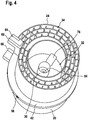
- FIG. 4 shows the heat exchanger 24 of the cathode gas processor 22 in an isometric view.
- the heat exchanger 24 of the cathode gas processor 22 is separated from the heat exchanger 20 of the anode gas processor 18 by the separator 42.
- the heat exchanger 24 of the cathode gas processor 22 heats fresh air from an environment of the fuel cell device 10 to reaction temperature and supplies it to the cathode 16 of the fuel cell unit 12.
- the fresh air is heated by the same heat transfer principle, which is also used in the heat exchanger 20 of the anode gas processor 18 through the heat exchanger 24 of the cathode gas processor 22.
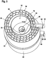
- the heat exchanger 24 of the cathode gas processor 22 is formed as a double spiral and guided around a receiving space 32, within which the afterburning unit 30 is arranged. Via a pipeline 76, the heated air is fed through the separating element 42 to the cathode 16 of the fuel cell unit 12 (see also FIG FIGS. 6 and 7 ). The hot exhaust gases of the afterburning unit 30 are passed through an opening 78 in the wall of the receiving space 32 from the receiving space 32 into the heat exchanger 24 of the cathode gas processor 22 (see FIG. 5 ).
- the heat exchangers 20, 24 each have a fluid guide unit 34, which is provided to guide gases within the heat exchanger 20, 24 parallel to a spiral axis 36 preferably meandering.
- the fluid guide units 34 each have a plurality of fluid guide elements 80, which are arranged within the heat exchangers 20, 24.
- FIG. 6 shows the separator 42 from the direction of the fuel cell unit 12.
- An output of the cathode 16 is designed as a short piece of pipe in the form of a diffuser 82.
- the exhaust gases of the cathode 16 are passed via the diffuser 82 into the receiving space 28, in which the fuel cell unit 12 is arranged, from where they are supplied through an opening 84 in the separating element 42 of the afterburner unit 30. Blowing from the cathode exhaust into the receiving space 28 prevents accumulation combustible gases in the fuel cell device 10.
- FIG. 7 shows the separator 42 from the direction of the post-combustion unit 30.
- the separator 42 has a bore which forms the branch 74 of the recirculation. According to FIG.
- the anode exhaust gas is divided into two volume flows.
- One of the volume flows is fed directly to the afterburner unit 30, whereas the other volume flow is supplied to the natural gas after leaving the fuel cell device 10 at the process connection 58 as a recirculation.
- Corresponding fluid lines in the separator 42 direct the anode off gas from the branch 74 to the center of the separator 42, where it is fed to the afterburner unit 30.
- In the center of the separating element 42 is an outlet of the pipeline 66, which is provided to supply the post-combustion unit 30 with fresh natural gas.
- the opening 84 which is intended to supply the afterburning unit 30, the cathode exhaust gas.
- FIG. 8 shows a sectional view of the fuel cell device 10, from which emerge again the arrangement of the individual components within the fuel cell device 10.
- an insulation 88 is disposed between the heat exchangers 20, 24 and a housing 86. The entire construction is fixed between a bottom plate 90 and a cover plate (not shown).
Landscapes
- Engineering & Computer Science (AREA)
- Chemical & Material Sciences (AREA)
- Chemical Kinetics & Catalysis (AREA)
- Sustainable Development (AREA)
- Sustainable Energy (AREA)
- Manufacturing & Machinery (AREA)
- Life Sciences & Earth Sciences (AREA)
- Electrochemistry (AREA)
- General Chemical & Material Sciences (AREA)
- Combustion & Propulsion (AREA)
- Physics & Mathematics (AREA)
- Thermal Sciences (AREA)
- Mechanical Engineering (AREA)
- General Engineering & Computer Science (AREA)
- Fuel Cell (AREA)
Description
- Die Erfindung betrifft eine Brennstoffzellenvorrichtung nach dem Oberbegriff des Patentanspruchs 1.
- Aus der
US 2003/134174 A1 ist bereits eine Brennstoffzellenvorrichtung mit einem Brennstoffzellenstack mit einem ersten Wärmeübertrager und einem zweiten Wärmeübertrager bekannt, welche spiralförmig um den Brennstoffzellenstack herumgeführt sind. Der erste Wärmeübertrager ist dazu vorgesehen, ein Brenngas, welches dem Brennstoffzellenstack anodenseitig zugeführt wird, zu erwärmen. Der zweite Wärmeübertrager ist dazu vorgesehen, eine Umgebungsluft, welche dem Brennstoffzellenstack kathodenseitig zugeführt wird, zu erwärmen. Dabei ist der erste Wärmeübetrager fluidtechnisch nicht von dem zweiten Wärmeübertrager getrennt. - Aus der
US 7,892,684 ist bereits eine Brennstoffzellenvorrichtung mit einem tubularen Brennstoffzellenstack und einem Wärmeübertrager bekannt, bei welcher der Wärmeübertrager spiralförmig um den Brennstoffzellenstack herumgeführt ist. Der Wärmeübertrager ist dazu vorgesehen, ein Brenngas, welches dem Brennstoffzellenstack anodenseitig zugeführt wird, oder eine Umgebungsluft, welche dem Brennstoffzellenstack kathodenseitig zugeführt wird, zu erwärmen. Ein gleichzeitiges Erwärmen beider Fluidströme mittels des Wärmeübertragers ist unmöglich. - Aus der
US 7,247,402 B2 ist eine Brennstoffzellenvorrichtung mit einem Brennstoffzellenstack und mit einem Wärmetauscher, welcher bekannt spiralförmig um den Brennstoffzellenstack herumgeführt und dazu vorgesehen ist, ein dem Brennstoffzellenstack zugeführtes Brenngas mittels einem dem Brennstoffzellenstack abgeführten Abgas zu erwärmen. - Die Erfindung geht aus von einer Brennstoffzellenvorrichtung, welche insbesondere dazu vorgesehen ist, mit einem Erdgas betrieben zu werden, mit einer Brennstoffzelleneinheit, welche zumindest eine Anode und zumindest eine Kathode aufweist, mit zumindest einem Anodengasprozessor, welcher zumindest einen ersten Wärmeübertrager aufweist, und mit zumindest einem Kathodengasprozessor, welcher zumindest einen zweiten Wärmeübertrager aufweist, wobei der zumindest eine erste Wärmeübertrager und der zumindest eine zweite Wärmeübertrager jeweils spiralförmig ausgebildet sind, wobei der zumindest eine erste Wärmeübertrager und der zumindest eine zweite Wärmeübertrager zumindest einen Teil einer baulichen Einheit bilden.
- Erfindungsgemäss ist vorgesehen, dass die Brennstoffzellenvorrichtung zumindest ein Trennelement aufweist, welches dazu vorgesehen ist, den zumindest einen ersten Wärmeübertrager fluidtechnisch von dem zumindest einen zweiten Wärmeübertrager zu trennen.
- Unter einer "Brennstoffzellenvorrichtung" soll in diesem Zusammenhang insbesondere eine Vorrichtung zu einer stationären und/oder mobilen Gewinnung insbesondere elektrischer und/oder thermischer Energie unter Verwendung zumindest einer Brennstoffzelleneinheit verstanden werden. Unter einer "Brennstoffzelleneinheit" soll in diesem Zusammenhang insbesondere eine Einheit mit zumindest einer Brennstoffzelle verstanden werden, welche dazu vorgesehen ist, zumindest eine chemische Reaktionsenergie zumindest eines, insbesondere kontinuierlich zugeführten, Brenngases, insbesondere Wasserstoff und/oder Kohlenstoffmonoxid, und zumindest eines Oxidationsmittels, insbesondere Sauerstoff, insbesondere in elektrische Energie umzuwandeln. Die zumindest eine Brennstoffzelle kann insbesondere als Festoxid-Brennstoffzelle (SOFC) ausgebildet sein. Vorzugsweise umfasst die zumindest eine Brennstoffzelleneinheit eine Vielzahl von Brennstoffzellen, welche insbesondere in einem, insbesondere tubularen und/oder planaren, Brennstoffzellenstack angeordnet sind. Unter "vorgesehen" soll insbesondere speziell programmiert, ausgelegt und/oder ausgestattet verstanden werden. Darunter, dass ein Objekt zu einer bestimmten Funktion vorgesehen ist, soll insbesondere verstanden werden, dass das Objekt diese bestimmte Funktion in zumindest einem Anwendungs- und/oder Betriebszustand erfüllt und/oder ausführt. Unter einem "Erdgas" soll in diesem Zusammenhang insbesondere ein Gas und/oder ein Gasgemisch, insbesondere ein Naturgasgemisch, verstanden werden, welches zumindest ein Alkan, insbesondere Methan, Ethan, Propan und/oder Butan umfasst. Ferner kann das Erdgas weitere Bestandteile aufweisen, wie insbesondere Kohlenstoffdioxid und/oder Stickstoff und/oder Sauerstoff und/oder Schwefelverbindungen.
- Unter einem "Gasprozessor" soll in diesem Zusammenhang insbesondere eine Einheit verstanden werden, welche dazu vorgesehen ist, ein insbesondere gasförmiges Fluid vor einer Zuleitung zu einer Anode und/oder zu einer Kathode der Brennstoffzelleneinheit für eine Verwendung innerhalb einer in der Brennstoffzelleneinheit ablaufenden Reaktion aufzubereiten. Insbesondere ist der zumindest eine Anodengasprozessor dazu vorgesehen, insbesondere das Erdgas und/oder ein Brenngas und/oder ein brenngashaltiges Gasgemisch auf eine Reaktionstemperatur zu erwärmen und/oder das Erdgas in ein Brenngas und/oder ein Brenngasgemisch zu überführen. Der zumindest eine Kathodengasprozessor ist insbesondere dazu vorgesehen, insbesondere eine Umgebungsluft auf eine Reaktionstemperatur zu erwärmen. Unter einem "Wärmeübertrager" soll in diesem Zusammenhang insbesondere eine Einheit verstanden werden, welche dazu vorgesehen ist, Wärme in Richtung eines Temperaturgefälles zwischen zumindest zwei insbesondere fluiden Stoffströmen zu übertragen, insbesondere in einem Gegenstrombetrieb. Der zumindest eine erste Wärmeübertrager ist insbesondere dazu vorgesehen, Wärme von zumindest einem fluiden Stoffstrom, insbesondere einem Abgas und vorzugsweise einem Anodenabgas der Brennstoffzelleneinheit, insbesondere auf das Erdgas und/oder ein Brenngas und/oder ein brenngashaltiges Gasgemisch, welches in zumindest einem Betriebszustand einer Anode der Brennstoffzelleneinheit zugeführt ist, zu übertragen. Der zumindest eine zweite Wärmeübertrager ist insbesondere dazu vorgesehen, Wärme von zumindest einem fluiden Stoffstrom, insbesondere einem Abgas und/oder einem Abgasgemisch der Brennstoffzelleneinheit, auf eine Umgebungsluft, welche einer in zumindest einem Betriebszustand einer Kathode der Brennstoffzelleneinheit zugeführt ist, zu übertragen.
- Darunter, dass der zumindest eine erste Wärmeübertrager und der zumindest eine zweite Wärmeübertrager jeweils "spiralförmig" ausgebildet sind, soll insbesondere verstanden werden, dass der zumindest eine erste Wärmeübertrager und der zumindest eine zweite Wärmeübertrager jeweils zumindest einen um jeweils eine Spiralachse verlaufenden Fluidkanal aufweisen, wobei ein Radius eines Verlaufs des zumindest einen Fluidkanals ausgehend von der Spiralachse kontinuierlich, insbesondere proportional zu einem Drehwinkel des Verlaufs des zumindest einen Fluidkanals um die Spiralachse, insbesondere bei einer Betrachtung entlang der Spiralachse, zunimmt. Vorzugsweise verlaufen der zumindest eine Fluidkanal des zumindest einen ersten Wärmeübertragers und der zumindest eine Fluidkanal des zumindest eine zweiten Wärmeübertragers um eine gemeinsame Spiralachse. Vorzugsweise weist der zumindest eine Fluidkanal zumindest einen ersten Abschnitt auf, welcher zumindest im Wesentlichen senkrecht zu der Spiralachse verläuft. Ferner kann der zumindest eine Fluidkanal insbesondere zumindest einen zweiten Abschnitt aufweisen, welcher zumindest im Wesentlichen senkrecht zur Spiralachse verläuft. Unter einem "Fluidkanal" soll in diesem Zusammenhang insbesondere ein zumindest von zwei, insbesondere gegenüberliegenden, Seiten, insbesondere zumindest im Wesentlichen gasdicht, geschlossener Kanal verstanden werden, welcher dazu vorgesehen ist, in zumindest einem Betriebszustand zumindest einen Fluidstrom durch den zumindest einen ersten Wärmeübertrager oder den zumindest einen zweiten Wärmeübertrager zu leiten.
- Durch die erfindungsgemäße Ausgestaltung kann eine gattungsgemäße Brennstoffzellenvorrichtung mit vorteilhaften Betriebseigenschaften bereitgestellt werden. Insbesondere können sowohl ein Brenngas, welches der Brennstoffzelleneinheit in zumindest einem Betriebszustand anodenseitig zugeführt wird, als auch eine Umgebungsluft, welche der Brennstoffzelleneinheit in zumindest einem Betriebszustand kathodenseitig zugeführt wird, vorteilhaft auf eine Reaktionstemperatur erwärmt werden, wodurch eine Effizienz der Brennstoffzelleneinheit vorteilhaft gesteigert werden kann. Ferner ermöglicht die spiralförmige Ausgestaltung des zumindest einen ersten Wärmeübertragers und des zumindest einen zweiten Wärmeübertragers eine vorteilhafte Reduktion eines Bauraumbedarfs.
- Des Weiteren wird vorgeschlagen, dass der zumindest eine erste Wärmeübertrager und/oder der zumindest eine zweite Wärmeübertrager als eine Doppelspirale ausgebildet ist. Darunter, dass der zumindest eine erste Wärmeübertrager und/oder der zumindest eine zweite Wärmeübertrager als eine "Doppelspirale ausgebildet ist", soll insbesondere verstanden werden, dass der zumindest eine erste Wärmeübertrager und/oder der zumindest eine zweite Wärmeübertrager jeweils zumindest zwei Fluidkanäle aufweist. Die zumindest zwei Fluidkanäle des zumindest einen ersten Wärmeübertragers und/oder des zumindest einen zweiten Wärmeübertragers weisen jeweils zumindest einen ersten Abschnitt auf, welcher zumindest im Wesentlichen senkrecht zu eine Spiralachse und, insbesondere konzentrisch, um die Spiralachse des zumindest einen ersten Wärmeübertragers und/oder des zumindest einen zweiten Wärmeübertragers verläuft. Ferner können die zumindest zwei Fluidkanäle jeweils insbesondere zumindest einen zweiten Abschnitt aufweisen, welcher zumindest im Wesentlichen senkrecht zur Spiralachse des zumindest einen ersten Wärmeübertragers und/oder des zumindest einen zweiten Wärmeübertragers verläuft. Vorzugsweise sind die zumindest zwei Fluidkanäle thermisch miteinander gekoppelt, vorzugsweise unmittelbar benachbart und weisen besonders vorteilhaft zumindest eine gemeinsame Wandung auf. Die zumindest zwei Fluidkanäle sind dabei insbesondere zumindest weitgehend fluidtechnisch voneinander getrennt. Hierdurch kann ein vorteilhaft effektiver Betrieb des zumindest einen ersten Wärmeübertragers und/oder des zumindest einen zweiten Wärmeübertragers, insbesondere nach einem Gegenstromprinzip, erreicht werden.
- Ferner wird vorgeschlagen, dass der zumindest eine Anodengasprozessor eine Reformereinheit aufweist, welche innerhalb des zumindest einen ersten Wärmeübertragers angeordnet ist. Unter einer "Reformereinheit" soll in diesem Zusammenhang insbesondere eine chemisch-technische Einheit zu zumindest einer Aufbereitung des Erdgases, insbesondere durch eine Dampfreformierung und/oder durch eine partielle Oxidation und/oder durch eine autotherme Reformierung, insbesondere zur Gewinnung zumindest eines Brenngases und/oder eines brenngashaltigen Gasgemischs, verstanden werden. Die Reformereinheit ist insbesondere teilweise und vorzugsweise vollständig innerhalb zumindest eines Fluidkanals des zumindest einen ersten Wärmeübertragers angeordnet. Hierdurch kann ein der Brennstoffzelleneinheit zugeführtes Erdgas vorteilhaft einfach in ein Brenngas und/oder in ein brenngashaltiges Gasgemisch überführt werden. Insbesondere kann durch die Anordnung einer Reformereinheit innerhalb des zumindest einen Wärmeübertragers auf eine zusätzliche externe Reformereinheit verzichtet werden, wodurch ein Bauraumbedarf vorteilhaft weiter reduziert werden kann.
- In einer bevorzugten Ausgestaltung der Erfindung wird vorgeschlagen, dass der zumindest eine erste Wärmeübertrager um einen ersten Aufnahmeraum herumgeführt ist, innerhalb dessen die Brennstoffzelleneinheit angeordnet ist. Darunter, dass ein Wärmeübertrager um einen Aufnahmeraum "herumgeführt" ist, soll insbesondere verstanden werden, dass zumindest ein Fluidkanal und vorzugsweise alle Fluidkanäle des Wärmeübertragers zumindest einmal und vorzugsweise mehrmals, insbesondere zumindest teilweise spiralförmig, um den Aufnahmeraum herum verlaufen. Unter einem "Aufnahmeraum" soll insbesondere ein räumlicher Bereich verstanden werden, der von einer sichtbaren Außenfläche gegenüberliegenden, insbesondere zumindest teilweise von außen nicht sichtbaren, Innenfläche eines Wärmeübertragers begrenzt ist, und zwar insbesondere von zumindest zwei und vorzugsweise von zumindest drei Seiten. Der erste Aufnahmeraum ist insbesondere in Umfangsrichtung zumindest im Wesentlichen von einer Innenfläche des zumindest einen ersten Wärmeübertragers umschlossen. Unter einer "Umfangsrichtung" eines Objekts soll insbesondere eine azimutale, senkrecht zu einer Längserstreckungsrichtung des Objekts angeordnete Richtung verstanden werden. Unter einer "Längserstreckungsrichtung" eines Objekts soll insbesondere eine Richtung verstanden werden, welche parallel ist zu einer längsten Kante eines kleinsten geometrischen Quaders, welcher das Objekt gerade noch umgibt. Darunter, dass der erste Aufnahmeraum von einer Innenfläche eines Wärmeübertragers "zumindest im Wesentlichen umschlossen" ist, soll insbesondere verstanden werden, dass die Innenfläche des Wärmeübertragers in einem montierten Zustand den Aufnahmeraum umschließt und ein Gesamtflächeninhalt aller Ausnehmungen in der Innenfläche des Wärmeübertragers insbesondere maximal 40 %, insbesondere höchstens 30 %, vorzugsweise maximal 20 % und besonders vorteilhaft höchstens 10 % eines Gesamtflächeninhalts der Innenfläche des Wärmeübertragers beträgt. Der erste Aufnahmeraum weist vorzugsweise eine zumindest im Wesentlichen kreisförmige Grundfläche auf, wobei eine Spiralachse des zumindest einen ersten Wärmeübertragers vorzugsweise einen Mittelpunkt der Grundfläche zumindest im Wesentlichen senkrecht schneidet. Hierdurch kann insbesondere in einem Zentrum einer von dem zumindest einen ersten Wärmeübertrager gebildeten Spirale ein Aufnahmeraum insbesondere für die Brennstoffzelleneinheit geschaffen werden. Ferner kann der Brennstoffzelleneinheit vorteilhaft einfach ein Fluid über den zumindest einen ersten Wärmeübertrager zugeführt und/oder zumindest ein Fluid über den zumindest einen ersten Wärmeübertrager von der Brennstoffzelleneinheit abgeführt werden. Des Weiteren kann vorteilhaft eine Abwärme der Brennstoffzelleneinheit genutzt werden.
- Ferner wird vorgeschlagen, dass der Kathodengasprozessor eine Nachbrenneinheit aufweist, welche dazu vorgesehen ist, zumindest einen brennbaren Bestandteil eines Abgases zumindest weitgehend nachzuverbrennen. Vorzugsweise ist die Nachbrenneinheit dazu vorgesehen, insbesondere innerhalb eines Anodenabgases enthaltenes Brenngas zumindest weitgehend zu oxidieren. Ein für eine Oxidation des Brenngases benötigter Sauerstoff ist der Nachbrenneinheit insbesondere in Form eines Kathodenabgases zuführbar. Insbesondere während eines Anlaufbetriebszustands der Brennstoffzellenvorrichtung ist die Nachbrenneinheit vorzugsweise mit Erdgas betreibbar. Insbesondere kann die Nachbrenneinheit einen katalytischen Nachbrenner und/oder einen Diffusionsbrenner und/oder einen Rekuperatorbrenner und/oder einen teil- und/oder vollvormischenden Brenner und/oder einen Porenbrenner umfassen. Hierdurch kann ein Ausstoß von Brenngas, insbesondere von Wasserstoff, vorteilhaft reduziert und somit eine Anlagensicherheit vorteilhaft gesteigert werden. Ferner kann eine chemische Energie des Anodenabgases vorteilhaft in Wärme umgewandelt werden.
- Des Weiteren wird vorgeschlagen, dass der zumindest eine zweite Wärmeübertrager um einen zweiten Aufnahmeraum herumgeführt ist, innerhalb dessen die Des Weiteren wird vorgeschlagen, dass der zumindest eine zweite Wärmeübertrager um einen zweiten Aufnahmeraum herumgeführt ist, innerhalb dessen die Nachbrenneinheit angeordnet ist. Der zweite Aufnahmeraum ist insbesondere in Umfangsrichtung zumindest im Wesentlichen von einer Innenfläche des zumindest einen zweiten Wärmeübertragers umschlossen. Der zweite Aufnahmeraum weist vorzugsweise eine zumindest im Wesentlichen kreisförmige Grundfläche auf, wobei eine Spiralachse des zumindest einen zweiten Wärmeübertragers vorzugsweise einen Mittelpunkt der Grundfläche zumindest im Wesentlichen senkrecht schneidet. Hierdurch kann insbesondere in einem Zentrum einer von dem zumindest einen zweiten Wärmeübertrager gebildeten Spirale ein Aufnahmeraum für die Nachbrenneinheit geschaffen werden. Ferner kann der Nachbrenneinheit vorteilhaft einfach ein Fluid über den zumindest einen zweiten Wärmeübertrager zugeführt und/oder zumindest ein Fluid über den zumindest einen zweiten Wärmeübertrager von der Nachbrenneinheit abgeführt werden. Des Weiteren kann vorteilhaft eine Abwärme der Nachbrenneinheit genutzt werden.
- Ferner wird vorgeschlagen, dass der zumindest eine erste Wärmeübertrager und/oder der zumindest eine zweite Wärmeübertrager eine Fluidleiteinheit aufweist, welche dazu vorgesehen ist, zumindest ein Fluid zumindest im Wesentlichen parallel zu einer Spiralachse mäanderförmig zu leiten. Hierzu weist die Fluidleiteinheit vorzugsweise eine Vielzahl von Fluidleitelementen auf, welche insbesondere entlang einer Fluidfließrichtung innerhalb zumindest eines Fluidkanals des zumindest einen ersten Wärmeübertragers und/oder des zumindest einen zweiten Wärmeübertragers angeordnet sind. Unter "zumindest im Wesentlichen parallel" soll insbesondere eine Ausrichtung einer Richtung relativ zu einer Bezugsrichtung, insbesondere in einer Ebene, verstanden werden, wobei die Richtung gegenüber der Bezugsrichtung eine Abweichung von höchstens 10°, insbesondere von maximal 7,5°, vorzugsweise von höchstens 5° und besonders vorteilhaft von maximal 2,5° aufweist. Hierdurch kann eine Effizienz des zumindest einen ersten Wärmeübertragers und/oder des zumindest einen zweiten Wärmeübertragers vorteilhaft gesteigert werden.
- Der zumindest eine erste Wärmeübertrager und der zumindest eine zweite Wärmeübertrager bilden zumindest einen Teil einer baulichen Einheit. Darunter, dass der zumindest eine erste Wärmeübertrager und der zumindest eine zweite Wärmeübertrager "zumindest einen Teil einer baulichen Einheit bilden", soll in diesem Zusammenhang insbesondere verstanden werden, dass der zumindest eine erste Wärmeübertrager und der zumindest eine zweite Wärmeübertrager zumindest in einem montierten Zustand der Brennstoffzellenvorrichtung, beispielsweise formschlüssig und/oder kraftschlüssig und/oder stoffschlüssig, unmittelbar und/oder mittelbar, beispielsweise über zumindest eine weitere Komponente der Brennstoffzellenvorrichtung, fest miteinander verbunden sind. Hierdurch kann eine vorteilhaft kompakte Bauweise der Brennstoffzellenvorrichtung erreicht werden. Ferner kann durch eine Ausbildung einer baulichen Einheit zumindest eines ersten Wärmeübertragers mit dem zumindest einen zweiten Wärmeübertrager eine vorteilhafte Dichtheit, insbesondere Gasdichtheit, erreicht werden.
- Die Brennstoffzellenvorrichtung weist zumindest ein Trennelement auf, welches dazu vorgesehen ist, den zumindest einen ersten Wärmeübertrager fluidtechnisch, vorzugsweise vollständig, von dem zumindest einen zweiten Wärmeübertrager zu trennen. Dadurch kann vorteilhaft eine Vermischung von zumindest einem und vorzugsweise aller fluiden Stoffströmen innerhalb zumindest eines Fluidkanals des zumindest einen ersten Wärmeübertragers mit zumindest einem und vorzugsweise allen fluiden Stoffströmen innerhalb zumindest eines Fluidkanals des zumindest einen zweiten Wärmeübertragers zumindest weitgehend vermieden werden. Unter einem "Trennelement" soll in diesem Zusammenhang ein, insbesondere scheibenartiges, Element verstanden werden, welches zumindest im Wesentlichen senkrecht zu einer Spiralachse des zumindest einen ersten Wärmeübertragers und des zumindest einen zweiten Wärmeübertragers zwischen dem zumindest einen ersten Wärmeübertrager und dem zumindest einen zweiten Wärmeübertrager angeordnet ist. Insbesondere ist der zumindest eine erste Wärmeübertrager und der zumindest eine zweite Wärmeübertrager jeweils zumindest einseitig zumindest im Wesentlichen gasdicht von dem zumindest einen Trennelement verschlossen. Zwischen das zumindest eine Trennelement und dem zumindest einen ersten Wärmeübertrager und/oder dem zumindest einen zweiten Wärmeübertrager kann insbesondere ein Hochtemperaturdichtelement eingebracht sein. Dabei kann der zumindest eine erste Wärmeübertrager und/oder der zumindest eine zweite Wärmeübertrager vorzugsweise über eine Vielzahl von Schraubverbindungen mit dem zumindest einen Trennelement verbunden sein. Alternativ kann das zumindest eine Trennelement einstückig mit dem zumindest einen ersten Wärmeübertrager und/oder dem zumindest einen zweiten Wärmeübertrager ausgebildet sein und insbesondere mittels
zumindest einen ersten Wärmeübertrager und dem zumindest einen zweiten Wärmeübertrager verbunden sein. - Des Weiteren wird vorgeschlagen, dass das zumindest eine Trennelement zumindest eine Fluidverbindung aufweist, welche dazu vorgesehen ist, der Nachbrenneinheit zumindest einen Teil eines Anodenabgases und/oder zumindest einen Teil des Erdgases und/oder zumindest einen Teil eines Kathodenabgases zuzuführen. Unter einer "Fluidverbindung" soll in diesem Zusammenhang insbesondere eine Einheit verstanden werden, welche zu einem Transport von insbesondere flüssigen und/oder gasförmigen Stoffen und/oder Stoffgemischen vorgesehen ist. Insbesondere umfasst die zumindest eine Fluidverbindung zumindest eine Hohlleitung, beispielsweise zumindest eine Rohr- und/oder Schlauchleitung. Vorzugsweise umfasst die zumindest eine Fluidverbindung zumindest eine Hohlleitung zu einer Anodenabgasrezirkulation und/oder zum Transport eines Anodenabgases zur Nachbrenneinheit und/oder zumindest eine Hohlleitung zum Transport eines Kathodenabgases zur Nachbrenneinheit und/oder zumindest eine Hohlleitung zum Transport von Erdgas zur Nachbrenneinheit. Die zumindest eine Fluidverbindung ist insbesondere an dem zumindest einen Trennelement angeordnet und/oder zumindest teilweise und vorzugsweise vollständig in das zumindest eine Trennelement eingebettet. Hierdurch können der Nachbrenneinheit vorteilhaft einfach für einen Betrieb der Nachbrenneinheit notwendige, insbesondere gasförmige, Fluide zugeführt werden.
- Die erfindungsgemäße Brennstoffzellenvorrichtung soll hierbei nicht auf die oben beschriebene Anwendung und Ausführungsform beschränkt sein. Insbesondere kann die erfindungsgemäße Brennstoffzellenvorrichtung zu einer Erfüllung einer hierin beschriebenen Funktionsweise eine von einer hierin genannten Anzahl von einzelnen Elementen, Bauteilen und Einheiten abweichende Anzahl aufweisen.
- Weitere Vorteile ergeben sich aus der folgenden Zeichnungsbeschreibung. In den Zeichnungen sind zwei Ausführungsbeispiele der Erfindung dargestellt. Die Zeichnungen, die Beschreibung und die Ansprüche enthalten zahlreiche Merkmale in Kombination. Der Fachmann wird die Merkmale zweckmäßigerweise auch einzeln betrachten und zu sinnvollen weiteren Kombinationen zusammenfassen.
- Es zeigen:
- Fig. 1
- eine vereinfachte Prinzipskizze einer Brennstoffzellenvorrichtung mit einem Anodengasprozessor und einem Kathodengasprozessor,
- Fig. 2
- eine isometrische Darstellung der Brennstoffvorrichtung aus
Figur 1 mit spiralförmigen Wärmeübertragern, - Fig. 3
- eine Draufsicht auf einen spiralförmigen Wärmeübertrager des Anodengasprozessors der Brennstoffzellenvorrichtung aus
Figur 1 , - Fig. 4
- eine weitere isometrische Darstellung der Brennstoffzellenvorrichtung aus
Figur 1 aus einem alternativen Blickwinkel, - Fig. 5
- eine weitere isometrische Darstellung der Brennstoffzellenvorrichtung aus
Figur 1 aus einem alternativen Blickwinkel, - Fig. 6
- ein Trennelement der Brennstoffzellenvorrichtung aus
Figur 1 , - Fig. 7
- das Trennelement aus
Figur 6 aus einem anderen Blickwinkel und - Fig. 8
- eine Teilschnittdarstellung der Brennstoffzellenvorrichtung aus
Figur 1 . -
Figur 1 zeigt in einer vereinfachten Prinzipskizze ein Flussdiagramm einer Brennstoffzellenvorrichtung 10 mit einer Brennstoffzelleneinheit 12. Die Brennstoffzelleneinheit 12 ist hier vereinfacht als eine Brennstoffzelle 46 zur Erzeugung elektrischer und/oder thermischer Energie dargestellt. Die elektrische Energie ist über zwei Gleichstromleitungen 48, 50 abgreifbar. Alternativ ist jedoch auch eine Ausbildung einer Brennstoffzelleneinheit als ein Brennstoffzellenstack mit einer Vielzahl von Brennstoffzellen denkbar. Die Brennstoffzelle 46 ist vorzugsweise als Festoxid-Brennstoffzelle ausgeführt. Die Brennstoffzelle 46 weist eine Anode 14 und eine Kathode 16 auf. - Ferner weist die Brennstoffzellenvorrichtung 10 einen Anodengasprozessor 18 und einen Kathodengasprozessor 22 auf. Der Anodengasprozessor 18 umfasst zwei Wärmeübertrager 52, 54 sowie eine zwischen die Wärmeübertrager 52, 54 geschaltete Reformereinheit 26. Der Kathodenprozessor umfasst eine Nachbrenneinheit 30 und einen Wärmeübertrager 24. Die Nachbrenneinheit 30 weist vorzugsweise einen katalytischen Brenner auf. Der Anodengasprozessor 18 und der Kathodengasprozessor 22 können jeweils sowohl als bauliche Einheit als auch als lediglich funktionelle Einheit ausgeführt sein.
- Über einen Prozessanschluss 56 wird der Brennstoffzellenvorrichtung 10 ein Frischgas zugeführt. Das Frischgas besteht aus frischem Erdgas und einem Rezirkulat, welches über einen weiteren Prozessanschluss 58 aus der Brennstoffzellenvorrichtung 10 abgeführt wird. Das Erdgas und das Rezirkulat werden außerhalb der Brennstoffzellenvorrichtung 10 zusammengeführt und mittels eines Verdichters 60 verdichtet.
- Das Frischgas wird in einem ersten Wärmeübertrager 52 des Anodengasprozessors 18 durch ein Anodenabgas der Brennstoffzelleneinheit 12 vorgewärmt. Im Anschluss wird es durch die Reformereinheit 26 in einen zweiten Wärmeübertrager 54 des Anodengasprozessors 18 geleitet, in dem es auf Reaktionstemperatur zwischen 650 °C und 850 °C erhitzt wird. Die Reformereinheit 26 dient einer endothermen DampfReformierung der im Erdgas vorhandenen langkettigen Alkane (CxH2(x+1), mit x > 1):
CxH2(x+1) + xH2O → xCO + (2x + 1)H2
- Das durch die Reformereinheit 26 gewonnene brenngashaltige Reformat wird der Anode 14 der Brennstoffzelleneinheit 12 zugeführt, wo es durch eine elektrochemische Reaktion unter Strom- und Wärmeproduktion umgesetzt wird. Ein heißes Anodenabgas der Brennstoffzelleneinheit 12 wird in den zweiten Wärmeübertrager 54 des Anodengasprozessors 18 geleitet, um das Frischgas auf Reaktionstemperatur zu erhitzen. Da das Frischgas nicht vollständig in der Anode 14 der Brennstoffzelleneinheit 12 umsetzbar ist, wird ein Teil des Anodenabgases, wie bereits beschrieben, dem frischen Erdgas als Rezirkulat zugeführt. Der Rest des Anodenabgases wird direkt der Nachbrenneinheit 30 zugeführt. Innerhalb der Nachbrenneinheit 30 werden brennbare Bestandteile des Anodenabgases nachverbrannt. Die in der Nachbrenneinheit 30 entstehende Wärme wird verwendet, um eine der Brennstoffzellenvorrichtung 10 über einen Prozessanschluss 62 zugeführte Umgebungsluft für die Kathode 16 zu erhitzen, und um beispielsweise Heizungswasser nach einem weiteren Prozessanschluss 64 zu erwärmen (hier nicht dargestellt).
- Für die elektrochemische Reaktion in der Kathode 16 wird die Umgebungsluft in dem Wärmeübertrager 24 des Kathodengasprozessors 22 auf die Reaktionstemperatur erhitzt. Nach dem Austritt aus der Brennstoffzelleneinheit 12 wird ein Kathodenabgas direkt in die Nachbrenneinheit 30 geleitet. Zusätzlich zu einem Teil des Anodenabgases kann der Nachbrenneinheit 30 Erdgas über eine Rohrleitung 66 zugeführt werden. Dies kann vor allem bei einem Aufheizvorgang der Brennstoffzellenvorrichtung 10 notwendig sein.
-
Figur 2 zeigt die Brennstoffzellenvorrichtung 10 in einer isometrischen Ansicht. Der Kathodengasprozessor 22 ist oberhalb des Anodengasprozessors 18 angeordnet. Der Wärmeübertrager 24 des Kathodengasprozessors 22 ist spiralförmig ausgebildet. Die Wärmeübertrager 52, 54 des Anodengasprozessors 18 sind zu einem spiralförmig verlaufenden spiralförmigen Wärmeübertrager 20 zusammengefasst (sieheFigur 3 ). Zwischen den Wärmeübertragern 20, 24 ist ein scheibenförmiges Trennelement 42 angeordnet. Das Trennelement 42 ist dazu vorgesehen zu verhindern, dass Gase des Anodengasprozessors 18 mit Gasen des Kathodengasprozessors 22 in Kontakt treten. Des Weiteren weist das Trennelement 42 Fluidverbindungen 44 auf, um den Kathodengasprozessor 22 und/oder den Anodengasprozessor 18 und/oder die Brennstoffzelleneinheit 12 verfahrenstechnisch miteinander zu verbinden (sieheFiguren 6 und7 ). Zwischen den Wärmeübertragern 20, 24 und dem Trennelement 42 kann beispielsweise jeweils eine Hochtemperaturdichtung (nicht dargestellt) eingebracht sein und die Wärmeübertrager 20, 24 jeweils über eine Vielzahl von Schraubverbindungen (nicht dargestellt) an dem Trennelement 42 befestigt sein, um eine ausreichende Dichtwirkung zu erzielen. -
Figur 3 zeigt den Anodengasprozessor 18 in einer Draufsicht aus einer in derFigur 2 gezeigten Blickrichtung 68. Der Wärmeübertrager 20 des Andodengasprozessors ist als Doppelspirale ausgebildet. Der Wärmeübertrager 20 ist um einen Aufnahmeraum 28 herumgeführt, innerhalb dessen die Brennstoffzelleneinheit 12 angeordnet ist. Die Reformereinheit 26 ist innerhalb des Wärmeübertragers 20, etwa auf der Hälfte des Strömungsweges, angeordnet. Alternativ und/oder zusätzlich zu der Reformereinheit 26 kann beispielsweise eine Entschwefelungseinheit und/oder eine andere, dem Fachmann sinnvoll erscheinende chemische Reaktoreinheit innerhalb des Wärmeübertragers 20 angeordnet sein. Im Inneren des Wärmeübertragers 20 wird das Reformat über die Rohrleitung 70 der Anode 14 der Brennstoffzelleneinheit 12 zugeführt. Nach Austritt aus der Anode 14 strömt das Anodenabgas durch eine weitere Rohrleitung 72 in den spiralförmigen Wärmeübertrager 20 zurück. Dort befindet sich etwa auf der Hälfte des Weges eine Abzweigung 74 für eine Rezirkulation des Anodenabgases. Der Wärmeübertrager 20 arbeitet nach dem Gegenstromprinzip. -
Figur 4 zeigt den Wärmeübertrager 24 des Kathodengasprozessors 22 in einer isometrischen Darstellung. Der Wärmeübertrager 24 des Kathodengasprozessors 22 ist vom Wärmeübertrager 20 des Anodengasprozessors 18 durch das Trennelement 42 abgetrennt. Der Wärmeübertrager 24 des Kathodengasprozessors 22 erwärmt Frischluft aus einer Umgebung der Brennstoffzellenvorrichtung 10 auf Reaktionstemperatur und führt sie der Kathode 16 der Brennstoffzelleneinheit 12 zu. Die Frischluft wird nach demselben Wärmeübertragungsprinzip, das auch im Wärmeübertrager 20 des Anodengasprozessors 18 verwendet wird, durch den Wärmeübertrager 24 des Kathodengasprozessors 22 erwärmt. Der Wärmeübertrager 24 des Kathodengasprozessors 22 ist als Doppelspirale ausgebildet und um einen Aufnahmeraum 32 herumgeführt, innerhalb dessen die Nachbrenneinheit 30 angeordnet ist. Über eine Rohrleitung 76 wird die erwärmte Luft durch das Trennelement 42 hindurch der Kathode 16 der Brennstoffzelleneinheit 12 zugeführt (siehe auchFiguren 6 und7 ). Die heißen Abgase der Nachbrenneinheit 30 werden über eine Öffnung 78 in der Wandung des Aufnahmeraums 32 aus dem Aufnahmeraum 32 in den Wärmeübertrager 24 des Kathodengasprozessors 22 geleitet (sieheFigur 5 ). - Die Wärmeübertrager 20, 24 weisen jeweils eine Fluidleiteinheit 34 auf, welche dazu vorgesehen ist, Gase innerhalb der Wärmeübertrager 20, 24 parallel zu einer Spiralachse 36 vorzugsweise mäanderförmig zu leiten. Hierzu weisen die Fluidleiteinheiten 34 jeweils eine Vielzahl von Fluidleitelementen 80 auf, welche innerhalb der Wärmeübertrager 20, 24 angeordnet sind.
-
Figur 6 zeigt das Trennelement 42 aus Richtung der Brennstoffzelleneinheit 12. Ein Ausgang der Kathode 16 ist als kurzes Rohrstück in Form eines Diffusors 82 ausgeführt. Die Abgase der Kathode 16 werden über den Diffusor 82 in den Aufnahmeraum 28 geleitet, in welchem die Brennstoffzelleneinheit 12 angeordnet ist, von wo sie durch eine Öffnung 84 in dem Trennelement 42 der Nachbrenneinheit 30 zugeführt werden. Das Blasen vom Kathodenabgas in den Aufnahmeraum 28 verhindert eine Ansammlung brennbarer Gase in der Brennstoffzellenvorrichtung 10.Figur 7 zeigt das Trennelement 42 aus Richtung der Nachbrenneinheit 30. Das Trennelement 42 weist eine Bohrung auf, welche die Abzweigung 74 der Rezirkulation ausbildet. GemäßFigur 1 wird das Anodenabgas in zwei Volumenströme aufgeteilt. Einer der Volumenströme wird direkt der Nachbrenneinheit 30 zugeleitet, wohingegen der andere Volumenstrom dem Erdgas nach Verlassen der Brennstoffzellenvorrichtung 10 am Prozessanschluss 58 als Rezirkulat zugeführt wird. Entsprechende Fluidleitungen in dem Trennelement 42 leiten das Anodenabgas von der Abzweigung 74 in die Mitte des Trennelements 42, wo es der Nachbrenneinheit 30 zugeführt wird. Im Zentrum des Trennelements 42 befindet sich ein Ausgang der Rohrleitung 66, welche dazu vorgesehen ist, der Nachbrenneinheit 30 frisches Erdgas zuzuführen. Um diese Zuleitung herum befindet sich in hufeisenförmiger Ausführung die Öffnung 84, welche dazu vorgesehen ist, der Nachbrenneinheit 30 das Kathodenabgas zuzuführen. -
Figur 8 zeigt eine Schnittdarstellung der Brennstoffzellenvorrichtung 10, aus welcher nochmals die Anordnung der einzelnen Komponenten innerhalb der Brennstoffzellenvorrichtung 10 hervorgehen. Zur Verringerung von Wärmeverlusten ist zwischen den Wärmeübertragern 20, 24 und einem Gehäuse 86 eine Isolierung 88 angeordnet. Die gesamte Konstruktion ist zwischen einer Bodenplatte 90 und einer Deckplatte (nicht dargestellt) befestigt.
Claims (8)
- Brennstoffzellenvorrichtung, mit einer Brennstoffzelleneinheit (12), welche zumindest eine Anode (14) und zumindest eine Kathode (16) aufweist, mit zumindest einem Anodengasprozessor (18), welcher zumindest einen ersten Wärmeübertrager (20) aufweist, und mit zumindest einem Kathodengasprozessor (22), welcher zumindest einen zweiten Wärmeübertrager (24) aufweist, wobei der zumindest eine erste Wärmeübertrager (20) und der zumindest eine zweite Wärmeübertrager (24) jeweils spiralförmig ausgebildet sind, wobei der zumindest eine erste Wärmeübertrager (20) und der zumindest eine zweite Wärmeübertrager (24) zumindest einen Teil einer baulichen Einheit bilden, gekennzeichnet durch zumindest ein Trennelement (42), welches dazu vorgesehen ist, den zumindest einen ersten Wärmeübertrager (20) fluidtechnisch von dem zumindest einen zweiten Wärmeübertrager (24) zu trennen.
- Brennstoffzellenvorrichtung nach Anspruch 1, dadurch gekennzeichnet, dass der zumindest eine erste Wärmeübertrager (20) und/oder der zumindest eine zweite Wärmeübertrager (24) als eine Doppelspirale ausgebildet ist.
- Brennstoffzellenvorrichtung nach Anspruch 1 oder 2, dadurch gekennzeichnet, dass der zumindest eine Anodengasprozessor (18) eine Reformereinheit (26) aufweist, welche innerhalb des zumindest einen ersten Wärmeübertragers (20) angeordnet ist.
- Brennstoffzellenvorrichtung nach einem der vorhergehenden Ansprüche, dadurch gekennzeichnet, dass der zumindest eine erste Wärmeübertrager (20) um einen ersten Aufnahmeraum (28) herumgeführt ist, innerhalb dessen die Brennstoffzelleneinheit (12) angeordnet ist.
- Brennstoffzellenvorrichtung nach einem der vorhergehenden Ansprüche, dadurch gekennzeichnet, dass der zumindest eine Kathodengasprozessor (22) eine Nachbrenneinheit (30) aufweist, welche dazu vorgesehen ist, zumindest einen brennbaren Bestandteil eines Abgases zumindest weitgehend nachzuverbrennen.
- Brennstoffzellenvorrichtung nach Anspruch 5, dadurch gekennzeichnet, dass der zumindest eine zweite Wärmeübertrager (24) um einen zweiten Aufnahmeraum (32) herumgeführt ist, innerhalb dessen die Nachbrenneinheit (30) angeordnet ist.
- Brennstoffzellenvorrichtung nach einem der vorhergehenden Ansprüche, dadurch gekennzeichnet, dass der zumindest eine erste Wärmeübertrager (20) und/oder der zumindest eine zweite Wärmeübertrager (24) eine Fluidleiteinheit (34) aufweist, welche dazu vorgesehen ist, zumindest ein Fluid zumindest im Wesentlichen parallel zu einer Spiralachse (36) mäanderförmig zu leiten.
- Brennstoffzellenvorrichtung nach Anspruch 1, dadurch gekennzeichnet, dass das zumindest eine Trennelement (42) zumindest eine Fluidverbindung (44) aufweist, welche dazu vorgesehen ist, der Nachbrenneinheit (30) zumindest einen Teil eines Anodenabgases und/oder zumindest einen Teil des Erdgases und/oder zumindest einen Teil eines Kathodenabgases zuzuführen.
Applications Claiming Priority (2)
| Application Number | Priority Date | Filing Date | Title |
|---|---|---|---|
| DE102014207143.7A DE102014207143A1 (de) | 2014-04-14 | 2014-04-14 | Brennstoffzellenvorrichtung |
| PCT/EP2015/057990 WO2015158669A1 (de) | 2014-04-14 | 2015-04-13 | Brennstoffzellenvorrichtung |
Publications (2)
| Publication Number | Publication Date |
|---|---|
| EP3132484A1 EP3132484A1 (de) | 2017-02-22 |
| EP3132484B1 true EP3132484B1 (de) | 2018-11-07 |
Family
ID=53002659
Family Applications (1)
| Application Number | Title | Priority Date | Filing Date |
|---|---|---|---|
| EP15718352.6A Active EP3132484B1 (de) | 2014-04-14 | 2015-04-13 | Brennstoffzellenvorrichtung |
Country Status (4)
| Country | Link |
|---|---|
| EP (1) | EP3132484B1 (de) |
| JP (1) | JP6423001B2 (de) |
| DE (1) | DE102014207143A1 (de) |
| WO (1) | WO2015158669A1 (de) |
Families Citing this family (2)
| Publication number | Priority date | Publication date | Assignee | Title |
|---|---|---|---|---|
| DE102016215453A1 (de) * | 2016-08-18 | 2018-02-22 | Robert Bosch Gmbh | Gasprozessoreinheit, sowie Brennstoffzellenvorrichtung mit einer solchen Gasprozessoreinheit |
| DE102016215973A1 (de) * | 2016-08-19 | 2018-02-22 | Robert Bosch Gmbh | Brennstoffzellenvorrichtung |
Family Cites Families (9)
| Publication number | Priority date | Publication date | Assignee | Title |
|---|---|---|---|---|
| DE19903168C2 (de) * | 1999-01-27 | 2002-06-20 | Xcellsis Gmbh | Spiralwärmetauscher |
| JP3925171B2 (ja) * | 2000-12-28 | 2007-06-06 | 三菱マテリアル株式会社 | 燃料電池モジュール |
| CA2408041A1 (en) * | 2000-12-28 | 2002-11-01 | Mitsubishi Materials Corporation | Fuel cell module and structure for gas supply to fuel cell |
| CA2473449C (en) * | 2002-02-05 | 2009-01-13 | Tokyo Gas Company Limited | Solid oxide fuel cell system |
| JP2004335165A (ja) * | 2003-05-01 | 2004-11-25 | Mitsubishi Materials Corp | 固体酸化物型燃料電池の運転方法 |
| JP4736309B2 (ja) * | 2003-05-01 | 2011-07-27 | 三菱マテリアル株式会社 | 固体電解質型燃料電池の運転開始時の予熱方法 |
| US7247402B2 (en) * | 2003-06-23 | 2007-07-24 | California Institute Of Technology | Power generator and method for forming the same |
| CA2452938A1 (en) | 2003-12-15 | 2005-06-15 | Alberta Research Council Inc. | Heat exchanger for solid oxide fuel cell stack |
| JP2005209579A (ja) * | 2004-01-26 | 2005-08-04 | Kyocera Corp | 燃料電池組立体 |
-
2014
- 2014-04-14 DE DE102014207143.7A patent/DE102014207143A1/de not_active Withdrawn
-
2015
- 2015-04-13 JP JP2016562923A patent/JP6423001B2/ja active Active
- 2015-04-13 EP EP15718352.6A patent/EP3132484B1/de active Active
- 2015-04-13 WO PCT/EP2015/057990 patent/WO2015158669A1/de not_active Ceased
Non-Patent Citations (1)
| Title |
|---|
| None * |
Also Published As
| Publication number | Publication date |
|---|---|
| DE102014207143A1 (de) | 2015-10-15 |
| WO2015158669A1 (de) | 2015-10-22 |
| EP3132484A1 (de) | 2017-02-22 |
| JP6423001B2 (ja) | 2018-11-14 |
| JP2017511585A (ja) | 2017-04-20 |
Similar Documents
| Publication | Publication Date | Title |
|---|---|---|
| DE102006020405B4 (de) | Brennstoffzellensystem und Verfahren zum Betreiben | |
| DE102006020097B4 (de) | Brennstoffzellensystem und Verfahren zum Betreiben | |
| DE102007039594B4 (de) | Energieerzeugungseinheit mit zumindest einer Hochtemperaturbrennstoffzelle | |
| EP1425244B1 (de) | Kompakte reformereinheit zur wasserstofferzeugung aus gasformigen kohlenwasserstoffen im kleinen leistungsbereich | |
| US9941535B2 (en) | Fuel cell module | |
| DE102014213102A1 (de) | Brennstoffzellenvorrichtung | |
| AT505940B1 (de) | Hochtemperaturbrennstoffzellensystem mit abgasrückführung | |
| WO2015158669A1 (de) | Brennstoffzellenvorrichtung | |
| EP3563444A1 (de) | Brennstoffzellenvorrichtung und verfahren zu einem anfahren der brennstoffzellenvorrichtung | |
| WO2005077821A1 (ja) | 選択酸化反応装置 | |
| WO2006066545A1 (de) | Reformer für eine brennstoffzelle | |
| DE102015216254B4 (de) | Brennstoffzellenmodul | |
| DE102014214848A1 (de) | Brennstoffzellenvorrichtung | |
| EP3316371B1 (de) | Brennstoffzellenvorrichtung mit durch kathodenabgas temperiertem reformer | |
| DE112013006536B4 (de) | Brennstoffzellenmodul | |
| DE19812155A1 (de) | Anordnung zur Energieumwandlung, umfassend mindestens zwei Brennstoffzellenstracks und mindestens eine Reformereinheit, sowie ein Brennstoffzellenkraftwerk | |
| DE102020202876A1 (de) | Peripheriegerätevorrichtung für eine Brennstoffzelleneinheit | |
| DE102007033864B4 (de) | Verfahren zum Betreiben einer Festoxidbrennstoffzellenanlage, Wärmetauscher für eine Festoxidbrennstoffzellenanlage und Festoxidbrennstoffzellenanlage | |
| EP3501052A1 (de) | Gasprozessoreinheit, sowie brennstoffzellenvorrichtung mit einer solchen gasprozessoreinheit | |
| DE102017202904A1 (de) | Brennstoffzellenvorrichtung | |
| EP3235038A1 (de) | Brennstoffzellenvorrichtung | |
| DE102008037028B4 (de) | Brennstoffzellensystem für gasförmige Kohlenwassserstoffe und dazugehöriges Betriebsverfahren | |
| DE102016215604A1 (de) | Brennstoffzellenvorrichtung | |
| EP3084869B1 (de) | Gaskreislauf für ein festoxidbrennstoffzellen-system und festoxidbrennstoffzellen-system | |
| AT507853B1 (de) | Sofc-brennstoffzelle mit einem externen dampfreformer |
Legal Events
| Date | Code | Title | Description |
|---|---|---|---|
| STAA | Information on the status of an ep patent application or granted ep patent |
Free format text: STATUS: THE INTERNATIONAL PUBLICATION HAS BEEN MADE |
|
| PUAI | Public reference made under article 153(3) epc to a published international application that has entered the european phase |
Free format text: ORIGINAL CODE: 0009012 |
|
| STAA | Information on the status of an ep patent application or granted ep patent |
Free format text: STATUS: REQUEST FOR EXAMINATION WAS MADE |
|
| 17P | Request for examination filed |
Effective date: 20161114 |
|
| AK | Designated contracting states |
Kind code of ref document: A1 Designated state(s): AL AT BE BG CH CY CZ DE DK EE ES FI FR GB GR HR HU IE IS IT LI LT LU LV MC MK MT NL NO PL PT RO RS SE SI SK SM TR |
|
| AX | Request for extension of the european patent |
Extension state: BA ME |
|
| DAV | Request for validation of the european patent (deleted) | ||
| DAX | Request for extension of the european patent (deleted) | ||
| REG | Reference to a national code |
Ref country code: DE Ref legal event code: R079 Ref document number: 502015006774 Country of ref document: DE Free format text: PREVIOUS MAIN CLASS: H01M0008060000 Ipc: H01M0008061200 |
|
| GRAP | Despatch of communication of intention to grant a patent |
Free format text: ORIGINAL CODE: EPIDOSNIGR1 |
|
| RIC1 | Information provided on ipc code assigned before grant |
Ipc: H01M 8/04007 20160101ALI20180517BHEP Ipc: H01M 8/04014 20160101ALI20180517BHEP Ipc: H01M 8/0612 20160101AFI20180517BHEP Ipc: H01M 8/124 20160101ALN20180517BHEP Ipc: F28D 21/00 20060101ALN20180517BHEP Ipc: F28D 9/04 20060101ALI20180517BHEP |
|
| STAA | Information on the status of an ep patent application or granted ep patent |
Free format text: STATUS: GRANT OF PATENT IS INTENDED |
|
| INTG | Intention to grant announced |
Effective date: 20180621 |
|
| RIC1 | Information provided on ipc code assigned before grant |
Ipc: F28D 9/04 20060101ALI20180612BHEP Ipc: F28D 21/00 20060101ALN20180612BHEP Ipc: H01M 8/0612 20160101AFI20180612BHEP Ipc: H01M 8/124 20160101ALN20180612BHEP Ipc: H01M 8/04014 20160101ALI20180612BHEP Ipc: H01M 8/04007 20160101ALI20180612BHEP |
|
| GRAS | Grant fee paid |
Free format text: ORIGINAL CODE: EPIDOSNIGR3 |
|
| GRAA | (expected) grant |
Free format text: ORIGINAL CODE: 0009210 |
|
| STAA | Information on the status of an ep patent application or granted ep patent |
Free format text: STATUS: THE PATENT HAS BEEN GRANTED |
|
| AK | Designated contracting states |
Kind code of ref document: B1 Designated state(s): AL AT BE BG CH CY CZ DE DK EE ES FI FR GB GR HR HU IE IS IT LI LT LU LV MC MK MT NL NO PL PT RO RS SE SI SK SM TR |
|
| REG | Reference to a national code |
Ref country code: GB Ref legal event code: FG4D Free format text: NOT ENGLISH |
|
| REG | Reference to a national code |
Ref country code: CH Ref legal event code: EP Ref country code: AT Ref legal event code: REF Ref document number: 1063174 Country of ref document: AT Kind code of ref document: T Effective date: 20181115 |
|
| REG | Reference to a national code |
Ref country code: DE Ref legal event code: R096 Ref document number: 502015006774 Country of ref document: DE |
|
| REG | Reference to a national code |
Ref country code: IE Ref legal event code: FG4D Free format text: LANGUAGE OF EP DOCUMENT: GERMAN |
|
| REG | Reference to a national code |
Ref country code: NL Ref legal event code: MP Effective date: 20181107 |
|
| REG | Reference to a national code |
Ref country code: LT Ref legal event code: MG4D |
|
| PG25 | Lapsed in a contracting state [announced via postgrant information from national office to epo] |
Ref country code: ES Free format text: LAPSE BECAUSE OF FAILURE TO SUBMIT A TRANSLATION OF THE DESCRIPTION OR TO PAY THE FEE WITHIN THE PRESCRIBED TIME-LIMIT Effective date: 20181107 Ref country code: LV Free format text: LAPSE BECAUSE OF FAILURE TO SUBMIT A TRANSLATION OF THE DESCRIPTION OR TO PAY THE FEE WITHIN THE PRESCRIBED TIME-LIMIT Effective date: 20181107 Ref country code: HR Free format text: LAPSE BECAUSE OF FAILURE TO SUBMIT A TRANSLATION OF THE DESCRIPTION OR TO PAY THE FEE WITHIN THE PRESCRIBED TIME-LIMIT Effective date: 20181107 Ref country code: BG Free format text: LAPSE BECAUSE OF FAILURE TO SUBMIT A TRANSLATION OF THE DESCRIPTION OR TO PAY THE FEE WITHIN THE PRESCRIBED TIME-LIMIT Effective date: 20190207 Ref country code: NO Free format text: LAPSE BECAUSE OF FAILURE TO SUBMIT A TRANSLATION OF THE DESCRIPTION OR TO PAY THE FEE WITHIN THE PRESCRIBED TIME-LIMIT Effective date: 20190207 Ref country code: LT Free format text: LAPSE BECAUSE OF FAILURE TO SUBMIT A TRANSLATION OF THE DESCRIPTION OR TO PAY THE FEE WITHIN THE PRESCRIBED TIME-LIMIT Effective date: 20181107 Ref country code: IS Free format text: LAPSE BECAUSE OF FAILURE TO SUBMIT A TRANSLATION OF THE DESCRIPTION OR TO PAY THE FEE WITHIN THE PRESCRIBED TIME-LIMIT Effective date: 20190307 Ref country code: FI Free format text: LAPSE BECAUSE OF FAILURE TO SUBMIT A TRANSLATION OF THE DESCRIPTION OR TO PAY THE FEE WITHIN THE PRESCRIBED TIME-LIMIT Effective date: 20181107 |
|
| PG25 | Lapsed in a contracting state [announced via postgrant information from national office to epo] |
Ref country code: SE Free format text: LAPSE BECAUSE OF FAILURE TO SUBMIT A TRANSLATION OF THE DESCRIPTION OR TO PAY THE FEE WITHIN THE PRESCRIBED TIME-LIMIT Effective date: 20181107 Ref country code: RS Free format text: LAPSE BECAUSE OF FAILURE TO SUBMIT A TRANSLATION OF THE DESCRIPTION OR TO PAY THE FEE WITHIN THE PRESCRIBED TIME-LIMIT Effective date: 20181107 Ref country code: NL Free format text: LAPSE BECAUSE OF FAILURE TO SUBMIT A TRANSLATION OF THE DESCRIPTION OR TO PAY THE FEE WITHIN THE PRESCRIBED TIME-LIMIT Effective date: 20181107 Ref country code: GR Free format text: LAPSE BECAUSE OF FAILURE TO SUBMIT A TRANSLATION OF THE DESCRIPTION OR TO PAY THE FEE WITHIN THE PRESCRIBED TIME-LIMIT Effective date: 20190208 Ref country code: PT Free format text: LAPSE BECAUSE OF FAILURE TO SUBMIT A TRANSLATION OF THE DESCRIPTION OR TO PAY THE FEE WITHIN THE PRESCRIBED TIME-LIMIT Effective date: 20190307 Ref country code: AL Free format text: LAPSE BECAUSE OF FAILURE TO SUBMIT A TRANSLATION OF THE DESCRIPTION OR TO PAY THE FEE WITHIN THE PRESCRIBED TIME-LIMIT Effective date: 20181107 |
|
| PG25 | Lapsed in a contracting state [announced via postgrant information from national office to epo] |
Ref country code: DK Free format text: LAPSE BECAUSE OF FAILURE TO SUBMIT A TRANSLATION OF THE DESCRIPTION OR TO PAY THE FEE WITHIN THE PRESCRIBED TIME-LIMIT Effective date: 20181107 Ref country code: IT Free format text: LAPSE BECAUSE OF FAILURE TO SUBMIT A TRANSLATION OF THE DESCRIPTION OR TO PAY THE FEE WITHIN THE PRESCRIBED TIME-LIMIT Effective date: 20181107 Ref country code: CZ Free format text: LAPSE BECAUSE OF FAILURE TO SUBMIT A TRANSLATION OF THE DESCRIPTION OR TO PAY THE FEE WITHIN THE PRESCRIBED TIME-LIMIT Effective date: 20181107 Ref country code: PL Free format text: LAPSE BECAUSE OF FAILURE TO SUBMIT A TRANSLATION OF THE DESCRIPTION OR TO PAY THE FEE WITHIN THE PRESCRIBED TIME-LIMIT Effective date: 20181107 |
|
| REG | Reference to a national code |
Ref country code: DE Ref legal event code: R097 Ref document number: 502015006774 Country of ref document: DE |
|
| PG25 | Lapsed in a contracting state [announced via postgrant information from national office to epo] |
Ref country code: SK Free format text: LAPSE BECAUSE OF FAILURE TO SUBMIT A TRANSLATION OF THE DESCRIPTION OR TO PAY THE FEE WITHIN THE PRESCRIBED TIME-LIMIT Effective date: 20181107 Ref country code: RO Free format text: LAPSE BECAUSE OF FAILURE TO SUBMIT A TRANSLATION OF THE DESCRIPTION OR TO PAY THE FEE WITHIN THE PRESCRIBED TIME-LIMIT Effective date: 20181107 Ref country code: EE Free format text: LAPSE BECAUSE OF FAILURE TO SUBMIT A TRANSLATION OF THE DESCRIPTION OR TO PAY THE FEE WITHIN THE PRESCRIBED TIME-LIMIT Effective date: 20181107 Ref country code: SM Free format text: LAPSE BECAUSE OF FAILURE TO SUBMIT A TRANSLATION OF THE DESCRIPTION OR TO PAY THE FEE WITHIN THE PRESCRIBED TIME-LIMIT Effective date: 20181107 |
|
| PLBE | No opposition filed within time limit |
Free format text: ORIGINAL CODE: 0009261 |
|
| STAA | Information on the status of an ep patent application or granted ep patent |
Free format text: STATUS: NO OPPOSITION FILED WITHIN TIME LIMIT |
|
| 26N | No opposition filed |
Effective date: 20190808 |
|
| PG25 | Lapsed in a contracting state [announced via postgrant information from national office to epo] |
Ref country code: SI Free format text: LAPSE BECAUSE OF FAILURE TO SUBMIT A TRANSLATION OF THE DESCRIPTION OR TO PAY THE FEE WITHIN THE PRESCRIBED TIME-LIMIT Effective date: 20181107 |
|
| REG | Reference to a national code |
Ref country code: CH Ref legal event code: PL |
|
| REG | Reference to a national code |
Ref country code: BE Ref legal event code: MM Effective date: 20190430 |
|
| PG25 | Lapsed in a contracting state [announced via postgrant information from national office to epo] |
Ref country code: LU Free format text: LAPSE BECAUSE OF NON-PAYMENT OF DUE FEES Effective date: 20190413 Ref country code: MC Free format text: LAPSE BECAUSE OF FAILURE TO SUBMIT A TRANSLATION OF THE DESCRIPTION OR TO PAY THE FEE WITHIN THE PRESCRIBED TIME-LIMIT Effective date: 20181107 |
|
| PG25 | Lapsed in a contracting state [announced via postgrant information from national office to epo] |
Ref country code: LI Free format text: LAPSE BECAUSE OF NON-PAYMENT OF DUE FEES Effective date: 20190430 Ref country code: CH Free format text: LAPSE BECAUSE OF NON-PAYMENT OF DUE FEES Effective date: 20190430 |
|
| PG25 | Lapsed in a contracting state [announced via postgrant information from national office to epo] |
Ref country code: BE Free format text: LAPSE BECAUSE OF NON-PAYMENT OF DUE FEES Effective date: 20190430 |
|
| PG25 | Lapsed in a contracting state [announced via postgrant information from national office to epo] |
Ref country code: TR Free format text: LAPSE BECAUSE OF FAILURE TO SUBMIT A TRANSLATION OF THE DESCRIPTION OR TO PAY THE FEE WITHIN THE PRESCRIBED TIME-LIMIT Effective date: 20181107 |
|
| PG25 | Lapsed in a contracting state [announced via postgrant information from national office to epo] |
Ref country code: IE Free format text: LAPSE BECAUSE OF NON-PAYMENT OF DUE FEES Effective date: 20190413 |
|
| PG25 | Lapsed in a contracting state [announced via postgrant information from national office to epo] |
Ref country code: CY Free format text: LAPSE BECAUSE OF FAILURE TO SUBMIT A TRANSLATION OF THE DESCRIPTION OR TO PAY THE FEE WITHIN THE PRESCRIBED TIME-LIMIT Effective date: 20181107 |
|
| REG | Reference to a national code |
Ref country code: AT Ref legal event code: MM01 Ref document number: 1063174 Country of ref document: AT Kind code of ref document: T Effective date: 20200413 |
|
| PG25 | Lapsed in a contracting state [announced via postgrant information from national office to epo] |
Ref country code: HU Free format text: LAPSE BECAUSE OF FAILURE TO SUBMIT A TRANSLATION OF THE DESCRIPTION OR TO PAY THE FEE WITHIN THE PRESCRIBED TIME-LIMIT; INVALID AB INITIO Effective date: 20150413 Ref country code: MT Free format text: LAPSE BECAUSE OF FAILURE TO SUBMIT A TRANSLATION OF THE DESCRIPTION OR TO PAY THE FEE WITHIN THE PRESCRIBED TIME-LIMIT Effective date: 20181107 |
|
| PG25 | Lapsed in a contracting state [announced via postgrant information from national office to epo] |
Ref country code: AT Free format text: LAPSE BECAUSE OF NON-PAYMENT OF DUE FEES Effective date: 20200413 |
|
| PG25 | Lapsed in a contracting state [announced via postgrant information from national office to epo] |
Ref country code: MK Free format text: LAPSE BECAUSE OF FAILURE TO SUBMIT A TRANSLATION OF THE DESCRIPTION OR TO PAY THE FEE WITHIN THE PRESCRIBED TIME-LIMIT Effective date: 20181107 |
|
| PGFP | Annual fee paid to national office [announced via postgrant information from national office to epo] |
Ref country code: DE Payment date: 20250624 Year of fee payment: 11 |
|
| PGFP | Annual fee paid to national office [announced via postgrant information from national office to epo] |
Ref country code: FR Payment date: 20250424 Year of fee payment: 11 |
|
| PGFP | Annual fee paid to national office [announced via postgrant information from national office to epo] |
Ref country code: GB Payment date: 20260324 Year of fee payment: 12 |