EP3132153B1 - Hydraulic damper - Google Patents
Hydraulic damper Download PDFInfo
- Publication number
- EP3132153B1 EP3132153B1 EP14889203.7A EP14889203A EP3132153B1 EP 3132153 B1 EP3132153 B1 EP 3132153B1 EP 14889203 A EP14889203 A EP 14889203A EP 3132153 B1 EP3132153 B1 EP 3132153B1
- Authority
- EP
- European Patent Office
- Prior art keywords
- working chamber
- stator
- rotor
- liquid medium
- channel
- Prior art date
- Legal status (The legal status is an assumption and is not a legal conclusion. Google has not performed a legal analysis and makes no representation as to the accuracy of the status listed.)
- Active
Links
Images

Classifications
-
- F—MECHANICAL ENGINEERING; LIGHTING; HEATING; WEAPONS; BLASTING
- F16—ENGINEERING ELEMENTS AND UNITS; GENERAL MEASURES FOR PRODUCING AND MAINTAINING EFFECTIVE FUNCTIONING OF MACHINES OR INSTALLATIONS; THERMAL INSULATION IN GENERAL
- F16D—COUPLINGS FOR TRANSMITTING ROTATION; CLUTCHES; BRAKES
- F16D57/00—Liquid-resistance brakes; Brakes using the internal friction of fluids or fluid-like media, e.g. powders
- F16D57/02—Liquid-resistance brakes; Brakes using the internal friction of fluids or fluid-like media, e.g. powders with blades or like members braked by the fluid
-
- F—MECHANICAL ENGINEERING; LIGHTING; HEATING; WEAPONS; BLASTING
- F16—ENGINEERING ELEMENTS AND UNITS; GENERAL MEASURES FOR PRODUCING AND MAINTAINING EFFECTIVE FUNCTIONING OF MACHINES OR INSTALLATIONS; THERMAL INSULATION IN GENERAL
- F16D—COUPLINGS FOR TRANSMITTING ROTATION; CLUTCHES; BRAKES
- F16D57/00—Liquid-resistance brakes; Brakes using the internal friction of fluids or fluid-like media, e.g. powders
- F16D57/04—Liquid-resistance brakes; Brakes using the internal friction of fluids or fluid-like media, e.g. powders with blades causing a directed flow, e.g. Föttinger type
-
- B—PERFORMING OPERATIONS; TRANSPORTING
- B60—VEHICLES IN GENERAL
- B60T—VEHICLE BRAKE CONTROL SYSTEMS OR PARTS THEREOF; BRAKE CONTROL SYSTEMS OR PARTS THEREOF, IN GENERAL; ARRANGEMENT OF BRAKING ELEMENTS ON VEHICLES IN GENERAL; PORTABLE DEVICES FOR PREVENTING UNWANTED MOVEMENT OF VEHICLES; VEHICLE MODIFICATIONS TO FACILITATE COOLING OF BRAKES
- B60T1/00—Arrangements of braking elements, i.e. of those parts where braking effect occurs specially for vehicles
- B60T1/02—Arrangements of braking elements, i.e. of those parts where braking effect occurs specially for vehicles acting by retarding wheels
- B60T1/08—Arrangements of braking elements, i.e. of those parts where braking effect occurs specially for vehicles acting by retarding wheels using fluid or powdered medium
- B60T1/087—Arrangements of braking elements, i.e. of those parts where braking effect occurs specially for vehicles acting by retarding wheels using fluid or powdered medium in hydrodynamic, i.e. non-positive displacement, retarders
-
- B—PERFORMING OPERATIONS; TRANSPORTING
- B60—VEHICLES IN GENERAL
- B60T—VEHICLE BRAKE CONTROL SYSTEMS OR PARTS THEREOF; BRAKE CONTROL SYSTEMS OR PARTS THEREOF, IN GENERAL; ARRANGEMENT OF BRAKING ELEMENTS ON VEHICLES IN GENERAL; PORTABLE DEVICES FOR PREVENTING UNWANTED MOVEMENT OF VEHICLES; VEHICLE MODIFICATIONS TO FACILITATE COOLING OF BRAKES
- B60T10/00—Control or regulation for continuous braking making use of fluid or powdered medium, e.g. for use when descending a long slope
- B60T10/02—Control or regulation for continuous braking making use of fluid or powdered medium, e.g. for use when descending a long slope with hydrodynamic brake
Definitions
- the present application relates to a hydraulic damper.
- Hydraulic damper also called hydraulic retarder
- Hydraulic damper is an energy-absorbing device converting mechanical energy into heat energy. It is especially employed in automotive auxiliary brake.
- Two adjacent impellers i.e. a driven rotor impeller and a fixed stator impeller, are arranged opposite so as to form a working chamber in which a flow loop is formed by liquid medium.
- the liquid medium is driven by the rotor impeller to rotate around an axis; meanwhile, the liquid medium is moved along the direction of the vanes of the rotor impeller, thrown towards the stator impeller.
- the liquid medium flows out of the stator impeller and turns back to impact the rotor impeller, which forms a resistance torque to the rotor impeller, and hinders the rotation of the rotor impeller, thus achieving a retarding brake on a gear shaft.
- the liquid medium coexists with the gaseous medium in the working chamber. If the gaseous medium is needed to be discharged out of the working chamber, some liquid medium may inevitably be discharged, which resulted in an excessive loss of the liquid medium in the working chamber.
- GB 1,213,692 describes a hydrodynamic brake comprising an annular housing constituting a stator, a rotor mounted for rotation within the housing, an annular channel surrounding the periphery of the housing and connected therewith by means of a peripheral gap in the housing, means to supply brake fluid to the housing and means to remove brake fluid from the housing to vary the degree of filling thereof.
- the removal means comprise an outlet from the annular channel and a drain pipe connected to the outlet and having a variable through flow resistance. The outlet is so shaped that the pressure in the drain pipe and hence the rate of removal of fluid from the housing is dependent on the rate of fluid flow in the annular channel which flow is created by rotation of the rotor.
- the arrangement being such that the degree of filling and hence the braking torque is automatically regulated in dependence on the rotational speed of the rotor.
- a hydraulic damper comprising a rotor, a stator and a drive shaft for driving the rotor, the rotor and the stator being mutually forming a working chamber in which liquid medium is accommodated, wherein the stator is provided in turn with an outlet, a nozzle, an exhaust channel, an ejector channel and an inlet; the outlet, the exhaust channel and the inlet are communicated with the working
- the angle between the lead-out direction of the outlet and velocity direction of the adjacent liquid medium in the working chamber is less than 90°, the angle between the lead-in direction of the inlet and the velocity direction of the adjacent liquid medium in the working chamber is less than 90°.
- the stator comprises a front stator and a rear stator
- the working chamber comprises a front working chamber and a rear working chamber
- the front stator is arranged at the front side of the rotor, and the front working chamber is formed mutually by the front stator and the front side of the rotor
- the rear stator is arranged at the rear side of the rotor, and the rear working chamber is formed mutually by the rear stator and the rear side of the rotor.
- the exhaust port of the exhaust channel is in communication with outside air.
- the hydraulic damper further comprises a storage tank for storing the liquid medium; the storage tank is in communication with the working chamber.
- the liquid medium is liquid water.
- An advantage of the present application is: by providing with the hydraulic damper which is equipped in turn with an outlet, a nozzle, an exhaust channel, an ejector channel and an inlet at the stator thereof, during the operation of the hydraulic damper, the liquid medium in the working chamber is led out of the outlet and entered into the ejector channel via the nozzle, because the channel width of the nozzle at the extension is smaller than that of the outlet and that of the ejector channel respectively, the liquid medium is in a high speed when passed through the nozzle, according to Bernoulli's principle, since the dynamic pressure of high-speed liquid medium increases and the static pressure decreases at the proximity to the junction of the exhaust channel and the ejector channel, there exists adsorption, so that the small amount of liquid medium discharged from the exhaust channel can be absorbed and returned to the working chamber via the ejector channel and the inlet, thus avoiding the loss of the liquid medium in the working chamber.
- the present application involves the Bernoulli's principle which was first proposed by Daniel Bernoulli in 1726.
- the content of the principle is: if the velocity of flowing liquid or gas is small, the local static pressure is high; if the velocity is large, the local static pressure is low.
- the hydraulic damper provided in this embodiment comprises a rotor 1, a stator 2 and a drive shaft 3.
- the drive shaft 3 drives the rotor 1.
- the rotor 1 and the stator 2 are respectively provided with vanes which are designed in accordance with hydrodynamics.
- the hydraulic damper provided in this embodiment further comprises a storage tank 5.
- the storage tank 5, communicated with the working chamber 4, is loaded with a large amount of liquid medium which is entered into the working chamber 4 via a pipe as needed.
- the liquid medium in the working chamber 4 is absorbed and accelerated by the vane of the rotor 1, and finally impacted towards the stator 2 from the side where the radius of the working chamber 4 is relatively larger; the velocity of the liquid medium is greatly reduced or even reverse through the vane of the stator 2, then the liquid medium is sent back to the rotor 1 by the stator 2 at the side where the radius of the working chamber 4 is relatively smaller; and so forth, during such process, the rotor 1 constantly transmits its own kinetic energy to the liquid medium which in turn converts the kinetic energy into heat through the great pressure received when the stator 2 makes a sharp change of direction (including the direction change inside the rotor), thus achieving dissipation of the kinetic energy of the rotor in the form of heat as well as the damping action of the rotor 1.
- the liquid medium in the working chamber 4 is liquid water; while in other embodiments, the liquid medium in the working chamber 4 may be other liquid substances instead of liquid water.
- the kinetic energy of the rotor 1 is converted by liquid water into heat, and due to high temperature, the liquid water will be changed into water vapor which is needed to be discharged from the working chamber 4.
- the stator 2 of the hydraulic damper has mainly been improved in this embodiment. As shown in Fig.
- the stator 2 is provided in turn with an outlet 21, a nozzle 22, an exhaust channel 23, an ejector channel 24 and an inlet 25; the outlet 21, the exhaust channel 23 and the inlet 25 are communicated with the working chamber 4 respectively; the ejector channel 24 is in communication with the outlet 21, the exhaust channel 23 and the inlet 25 respectively; the nozzle 22 is arranged at the junction where the outlet 21 is connected with the exhaust channel 23 and the ejector channel 24; the nozzle 22 is extended along the lead-out direction of the outlet 21 to the junction where the exhaust channel 23 is connected with the ejector channel 24, and the channel width of the nozzle 22 at the extension is smaller than that of the outlet 21 and that of the ejector channel 24 respectively.
- the liquid medium discharged from the exhaust channel 23 can be effectively recycled to prevent loss of the liquid medium in the working chamber 4.
- a kind of special ways that the liquid medium discharged from the exhaust channel 23 is recycled by the stator 2 is: when the hydraulic damper works, the liquid medium in the working chamber 4 is led out of the outlet 21 of the stator 2 and entered into the ejector channel 24 via the nozzle 22, because the channel width of the nozzle 22 at the extension is smaller than that of the outlet 21 and that of the ejector channel 24 respectively, the liquid medium is in a high speed when passed through the nozzle 22, according to the Bernoulli's principle, since the dynamic pressure of high-speed liquid medium increases and the static pressure decreases at the proximity to the junction of the exhaust channel 23 and the ejector channel 24, there exists adsorption, so that the small amount of liquid medium discharged from the exhaust channel 23 can be absorbed and returned to the working chamber 4 via the ejector channel 24 and the inlet 25, thus
- the angle between the lead-out direction of the outlet 21 and velocity direction of the adjacent liquid medium in the working chamber 4 is less than 90°, and the angle between the lead-in direction of the inlet 25 and the velocity direction of the adjacent liquid medium in the working chamber 4 is less than 90°.
- the outlet 21 is designed to be able to lead out the energy of the liquid medium in the working chamber 4 as much as possible
- the inlet 25 is designed to be able to minimize the energy of the liquid medium required to return to the working chamber 4.
- the exhaust channel 23, used for discharging the air in the working chamber 4 to the outside, is provided with a plurality of exhaust ports, apparently, the exhaust port of the exhaust channel 23 is in communication with outside air.
- the working chamber 4 of the hydraulic damper comprises a front working chamber 41 and a rear working chamber 42
- the stator 2 in this embodiment comprises a front stator and a rear stator
- the front stator is arranged at the front side of the rotor 1
- the rear stator is arranged at the rear side of the rotor 1
- the front working chamber 41 is formed mutually by the front stator and the front side of the rotor 1
- the rear working chamber 42 is formed mutually by the rear stator and the rear side of the rotor 1.
Landscapes
- Engineering & Computer Science (AREA)
- Mechanical Engineering (AREA)
- General Engineering & Computer Science (AREA)
- Physics & Mathematics (AREA)
- Fluid Mechanics (AREA)
- Transportation (AREA)
- Braking Arrangements (AREA)
- Jet Pumps And Other Pumps (AREA)
- Motor Or Generator Cooling System (AREA)
- Fluid-Damping Devices (AREA)
Description
- The present application relates to a hydraulic damper.
- Hydraulic damper (also called hydraulic retarder) is an energy-absorbing device converting mechanical energy into heat energy. It is especially employed in automotive auxiliary brake. Two adjacent impellers, i.e. a driven rotor impeller and a fixed stator impeller, are arranged opposite so as to form a working chamber in which a flow loop is formed by liquid medium. The liquid medium is driven by the rotor impeller to rotate around an axis; meanwhile, the liquid medium is moved along the direction of the vanes of the rotor impeller, thrown towards the stator impeller. Due to the reaction force exerted on the liquid medium by the stator impeller, the liquid medium flows out of the stator impeller and turns back to impact the rotor impeller, which forms a resistance torque to the rotor impeller, and hinders the rotation of the rotor impeller, thus achieving a retarding brake on a gear shaft.
- When the hydraulic damper works, some liquid medium will be vaporized and converted into gaseous medium with an increased temperature of the liquid medium in the working chamber. If the temperature is high during the operation of the hydraulic damper, especially when the vapor pressure of the employed liquid medium is large, it must manage to discharge the generated gaseous medium, otherwise, the hydraulic damper will be damaged or even exploded due to the excessive pressure in the working chamber.
- Since there is no clear dividing line between the liquid medium and the gaseous medium in the working chamber when the hydraulic damper works, in most cases, the liquid medium coexists with the gaseous medium in the working chamber. If the gaseous medium is needed to be discharged out of the working chamber, some liquid medium may inevitably be discharged, which resulted in an excessive loss of the liquid medium in the working chamber.
-
GB 1,213,692 - Aiming to solve the problem that the liquid medium in the working chamber is ran off when the existed hydraulic damper works, a hydraulic damper is provided in the present application, comprising a rotor, a stator and a drive shaft for driving the rotor, the rotor and the stator being mutually forming a working chamber in which liquid medium is accommodated, wherein the stator is provided in turn with an outlet, a nozzle, an exhaust channel, an ejector channel and an inlet;
the outlet, the exhaust channel and the inlet are communicated with the working - chamber respectively;
- the ejector channel is in communication with the outlet, the exhaust channel and the inlet respectively;
- the nozzle is arranged at the junction where the outlet is connected with the exhaust channel and the ejector channel;
- the nozzle is extended along the lead-out direction of the outlet to the junction where the exhaust channel is connected with the ejector channel, and the channel width of the nozzle at the extension is smaller than that of the outlet and that of the ejector channel respectively.
- In an embodiment, the angle between the lead-out direction of the outlet and velocity direction of the adjacent liquid medium in the working chamber is less than 90°, the angle between the lead-in direction of the inlet and the velocity direction of the adjacent liquid medium in the working chamber is less than 90°.
- In an embodiment, the stator comprises a front stator and a rear stator, the working chamber comprises a front working chamber and a rear working chamber;
the front stator is arranged at the front side of the rotor, and the front working chamber is formed mutually by the front stator and the front side of the rotor;
the rear stator is arranged at the rear side of the rotor, and the rear working chamber is formed mutually by the rear stator and the rear side of the rotor. - In an embodiment, the exhaust port of the exhaust channel is in communication with outside air.
- In an embodiment, the hydraulic damper further comprises a storage tank for storing the liquid medium; the storage tank is in communication with the working chamber.
- In an embodiment, the liquid medium is liquid water.
- An advantage of the present application is: by providing with the hydraulic damper which is equipped in turn with an outlet, a nozzle, an exhaust channel, an ejector channel and an inlet at the stator thereof, during the operation of the hydraulic damper, the liquid medium in the working chamber is led out of the outlet and entered into the ejector channel via the nozzle, because the channel width of the nozzle at the extension is smaller than that of the outlet and that of the ejector channel respectively, the liquid medium is in a high speed when passed through the nozzle, according to Bernoulli's principle, since the dynamic pressure of high-speed liquid medium increases and the static pressure decreases at the proximity to the junction of the exhaust channel and the ejector channel, there exists adsorption, so that the small amount of liquid medium discharged from the exhaust channel can be absorbed and returned to the working chamber via the ejector channel and the inlet, thus avoiding the loss of the liquid medium in the working chamber.
-
-
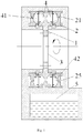
Fig. 1 is a schematic structural view of the hydraulic damper according to an embodiment of the present application; -
Fig. 2 is a schematic structural view of the stator according to an embodiment of the present application. - The present invention will be described in further details with following specific embodiments in conjunction with the accompanying drawings.
- The present application involves the Bernoulli's principle which was first proposed by Daniel Bernoulli in 1726. The content of the principle is: if the velocity of flowing liquid or gas is small, the local static pressure is high; if the velocity is large, the local static pressure is low.
- As shown in
Fig. 1 , the hydraulic damper provided in this embodiment comprises arotor 1, astator 2 and a drive shaft 3. The drive shaft 3 drives therotor 1. Therotor 1 and thestator 2, provided with a certain space therebetween, mutually form a working chamber 4 in which liquid medium is accommodated when the hydraulic damper works. - The
rotor 1 and thestator 2 are respectively provided with vanes which are designed in accordance with hydrodynamics. To fill the working chamber 4 with liquid medium, the hydraulic damper provided in this embodiment further comprises astorage tank 5. Thestorage tank 5, communicated with the working chamber 4, is loaded with a large amount of liquid medium which is entered into the working chamber 4 via a pipe as needed. When the hydraulic damper works, the liquid medium in the working chamber 4 is absorbed and accelerated by the vane of therotor 1, and finally impacted towards thestator 2 from the side where the radius of the working chamber 4 is relatively larger; the velocity of the liquid medium is greatly reduced or even reverse through the vane of thestator 2, then the liquid medium is sent back to therotor 1 by thestator 2 at the side where the radius of the working chamber 4 is relatively smaller; and so forth, during such process, therotor 1 constantly transmits its own kinetic energy to the liquid medium which in turn converts the kinetic energy into heat through the great pressure received when thestator 2 makes a sharp change of direction (including the direction change inside the rotor), thus achieving dissipation of the kinetic energy of the rotor in the form of heat as well as the damping action of therotor 1. - In the hydraulic damper provided in this embodiment, the liquid medium in the working chamber 4 is liquid water; while in other embodiments, the liquid medium in the working chamber 4 may be other liquid substances instead of liquid water.
- During the operation of the hydraulic damper provided in this embodiment, the kinetic energy of the
rotor 1 is converted by liquid water into heat, and due to high temperature, the liquid water will be changed into water vapor which is needed to be discharged from the working chamber 4. When the water vapor is discharged, part of the liquid water will also be discharged. In order to reduce the loss of the liquid water in the working chamber 4, thestator 2 of the hydraulic damper has mainly been improved in this embodiment. As shown inFig. 2 , thestator 2 is provided in turn with anoutlet 21, anozzle 22, anexhaust channel 23, anejector channel 24 and aninlet 25; theoutlet 21, theexhaust channel 23 and theinlet 25 are communicated with the working chamber 4 respectively; theejector channel 24 is in communication with theoutlet 21, theexhaust channel 23 and theinlet 25 respectively; thenozzle 22 is arranged at the junction where theoutlet 21 is connected with theexhaust channel 23 and theejector channel 24; thenozzle 22 is extended along the lead-out direction of theoutlet 21 to the junction where theexhaust channel 23 is connected with theejector channel 24, and the channel width of thenozzle 22 at the extension is smaller than that of theoutlet 21 and that of theejector channel 24 respectively. - With the special structure of the
stator 2 of the hydraulic damper provided in this embodiment, the liquid medium discharged from theexhaust channel 23 can be effectively recycled to prevent loss of the liquid medium in the working chamber 4. A kind of special ways that the liquid medium discharged from theexhaust channel 23 is recycled by thestator 2 is: when the hydraulic damper works, the liquid medium in the working chamber 4 is led out of theoutlet 21 of thestator 2 and entered into theejector channel 24 via thenozzle 22, because the channel width of thenozzle 22 at the extension is smaller than that of theoutlet 21 and that of theejector channel 24 respectively, the liquid medium is in a high speed when passed through thenozzle 22, according to the Bernoulli's principle, since the dynamic pressure of high-speed liquid medium increases and the static pressure decreases at the proximity to the junction of theexhaust channel 23 and theejector channel 24, there exists adsorption, so that the small amount of liquid medium discharged from theexhaust channel 23 can be absorbed and returned to the working chamber 4 via theejector channel 24 and theinlet 25, thus avoiding the loss of the liquid medium in the working chamber 4. - In this embodiment, since the liquid medium in the working chamber 4 is drawn through the
outlet 21 and the liquid medium in theejector channel 24 is returned to the working chamber 4 through theinlet 25, the angle between the lead-out direction of theoutlet 21 and velocity direction of the adjacent liquid medium in the working chamber 4 is less than 90°, and the angle between the lead-in direction of theinlet 25 and the velocity direction of the adjacent liquid medium in the working chamber 4 is less than 90°. Specially, theoutlet 21 is designed to be able to lead out the energy of the liquid medium in the working chamber 4 as much as possible, theinlet 25 is designed to be able to minimize the energy of the liquid medium required to return to the working chamber 4. In this embodiment, there is a plurality ofoutlet 21 and a plurality ofinlet 25; theexhaust channel 23, used for discharging the air in the working chamber 4 to the outside, is provided with a plurality of exhaust ports, apparently, the exhaust port of theexhaust channel 23 is in communication with outside air. - In this embodiment, the working chamber 4 of the hydraulic damper comprises a
front working chamber 41 and arear working chamber 42, in particular, thestator 2 in this embodiment comprises a front stator and a rear stator, the front stator is arranged at the front side of therotor 1, the rear stator is arranged at the rear side of therotor 1, thefront working chamber 41 is formed mutually by the front stator and the front side of therotor 1, and therear working chamber 42 is formed mutually by the rear stator and the rear side of therotor 1. Through the joint action on therotor 1 made by the front stator and the rear stator, the damping effort of therotor 1 can be effectively improved, which further enhances the damping effort of the hydraulic damper. According to actual needs, only thefront working chamber 41 or therear working chamber 42 is provided in the hydraulic damper in other embodiments. - What is described above is a further detailed explanation of the present invention in combination with specific embodiments; however, it cannot be considered that the specific embodiments of the present invention are only limited to the explanation. For those of ordinary skill in the art, some simple deductions or replacements can also be made under the premise of the concept of the present invention.
Claims (6)
- A hydraulic damper, comprising a rotor (1), a stator (2) and a drive shaft (3) for driving the rotor (1), the rotor (1) and the stator (2) being mutually forming a working chamber (4) in which liquid medium is accommodated, wherein the stator (2) is provided in turn with an outlet (21), a nozzle (22), an exhaust channel (23), an ejector channel (24) and an inlet (25);
the outlet (21), the exhaust channel (23) and the inlet (25) are communicated with the working chamber (4) respectively;
the ejector channel (24) is in communication with the outlet (21),the
exhaust channel (23) and the inlet (25) respectively;
the nozzle (22) is arranged at the junction where the outlet (21) is connected with the exhaust channel (23) and the ejector channel (24);
the nozzle (22) is extended along the lead-out direction of the outlet (21) to the junction where the exhaust channel (23) is connected with the ejector channel (24), and the channel width of the nozzle (22) at the extension is smaller than that of the outlet (21) and that of the ejector channel (24) respectively. - The hydraulic damper according to claim 1, wherein the angle between the lead-out direction of the outlet (21) and velocity direction of the adjacent liquid medium in the working chamber (4) is less than 90°, the angle between the lead-in direction of the inlet (25) and the velocity direction of the adjacent liquid medium in the working chamber (4) is less than 90°.
- The hydraulic damper according to claim 2, wherein the stator (2) comprises a front stator and a rear stator, the working chamber (4) comprises a front working chamber (41) and a rear working chamber (42);
the front stator is arranged at the front side of the rotor (1), and the front working chamber (41) is formed mutually by the front stator and the front side of the rotor (1);
the rear stator is arranged at the rear side of the rotor (1), and the rear working chamber (42) is formed mutually by the rear stator and the rear side of the rotor (1). - The hydraulic damper according to claim 1, wherein the exhaust port of the exhaust channel (23) is in communication with outside air.
- The hydraulic damper according to claim 1, further comprising a storage tank (5) for storing the liquid medium;
the storage tank (5) is in communication with the working chamber (4). - The hydraulic damper according to any one of claims 1-5, wherein the liquid medium is liquid water.
Applications Claiming Priority (2)
| Application Number | Priority Date | Filing Date | Title |
|---|---|---|---|
| CN201410153074.9A CN103967972B (en) | 2014-04-16 | 2014-04-16 | A kind of hydraulic retarder |
| PCT/CN2014/086649 WO2015158104A1 (en) | 2014-04-16 | 2014-09-16 | Hydraulic damper |
Publications (3)
| Publication Number | Publication Date |
|---|---|
| EP3132153A1 EP3132153A1 (en) | 2017-02-22 |
| EP3132153A4 EP3132153A4 (en) | 2017-12-27 |
| EP3132153B1 true EP3132153B1 (en) | 2019-10-02 |
Family
ID=51237849
Family Applications (1)
| Application Number | Title | Priority Date | Filing Date |
|---|---|---|---|
| EP14889203.7A Active EP3132153B1 (en) | 2014-04-16 | 2014-09-16 | Hydraulic damper |
Country Status (11)
| Country | Link |
|---|---|
| US (1) | US10138959B2 (en) |
| EP (1) | EP3132153B1 (en) |
| JP (1) | JP6607858B2 (en) |
| KR (1) | KR101846505B1 (en) |
| CN (1) | CN103967972B (en) |
| AU (1) | AU2014390837B2 (en) |
| CA (1) | CA2930196C (en) |
| ES (1) | ES2759982T3 (en) |
| FR (1) | FR3020105B1 (en) |
| RU (1) | RU2643123C1 (en) |
| WO (1) | WO2015158104A1 (en) |
Families Citing this family (3)
| Publication number | Priority date | Publication date | Assignee | Title |
|---|---|---|---|---|
| CN103967972B (en) | 2014-04-16 | 2016-04-27 | 李天维 | A kind of hydraulic retarder |
| CN113323973B (en) * | 2021-06-29 | 2022-01-28 | 吉林大学 | A hydraulic retarder with a rotor with a device for reducing no-load loss |
| CN114704564B (en) * | 2022-03-31 | 2024-06-14 | 贵阳丽天苍泰科技有限公司 | Hydraulic retarder |
Family Cites Families (26)
| Publication number | Priority date | Publication date | Assignee | Title |
|---|---|---|---|---|
| US2287130A (en) * | 1941-02-26 | 1942-06-23 | Parkersburg Rig & Reed Company | Hydrodynamic brake mechanism |
| US2768711A (en) * | 1951-10-12 | 1956-10-30 | Clayton Manufacturing Co | Hydro-kinetic apparatus |
| US3476218A (en) * | 1967-01-07 | 1969-11-04 | Maybach Mercedes Benz Motorenb | Hydrodynamic brake and regulating means therefor |
| SU399653A1 (en) * | 1971-06-30 | 1973-10-03 | HYDRAULIC BRAKE | |
| JPS4865975U (en) * | 1971-11-30 | 1973-08-21 | ||
| US4164994A (en) * | 1975-08-19 | 1979-08-21 | Firma Carl Schenck Ag | Hydraulic eddy brake |
| SU804941A1 (en) * | 1979-02-16 | 1981-02-15 | Курганский машиностроительный институт | Hydrodynamic decelerating brake |
| DE3545660C1 (en) * | 1985-12-21 | 1987-06-25 | Voith Turbo Kg | Hydrodynamic flow circuit with a device for reducing the air ventilation capacity |
| DE4442219A1 (en) | 1994-11-26 | 1995-06-01 | Voith Turbo Kg | Vehicle braking system with hydrodynamic retarder |
| DE10017688A1 (en) * | 2000-04-08 | 2001-10-11 | Rohs Voigt Patentverwertungsge | Spring element, especially for torsional vibration dampers |
| SE516896C2 (en) * | 2000-07-07 | 2002-03-19 | Scania Cv Ab | Hydrodynamic brake with two media |
| JP2002087222A (en) * | 2000-09-18 | 2002-03-27 | Exedy Corp | Fluid retarder |
| CN100348870C (en) * | 2004-05-20 | 2007-11-14 | 李天维 | A seam-type air-flow lead-jetting device |
| CN100491746C (en) * | 2006-09-04 | 2009-05-27 | 汪京涛 | Gas jet negative pressure suction device |
| DE102010004835A1 (en) * | 2010-01-15 | 2011-07-21 | Voith Patent GmbH, 89522 | Hydrodynamic machine and method for minimizing the drag power of such |
| DE102011115033B3 (en) * | 2011-10-07 | 2012-12-06 | Voith Patent Gmbh | Hydrodynamic machine such as hydrodynamic retarder used in power train of vehicle, has deformable diaphragm membrane that is placed in one of the branch lines or in the region of branch from common working medium supply channel |
| DE102011120644A1 (en) * | 2011-12-09 | 2013-06-13 | Voith Patent Gmbh | Motor vehicle drive train with a decoupled hydrodynamic retarder and control method therefor |
| DE102011120620B4 (en) * | 2011-12-09 | 2013-09-19 | Voith Patent Gmbh | Hydrodynamic retarder and method of actuating such |
| DE102012004332A1 (en) * | 2012-03-07 | 2013-09-12 | Voith Patent Gmbh | Hydrodynamic retarder and method for controlling the power transmission of such |
| CN103573901B (en) * | 2012-08-04 | 2015-11-25 | 李天维 | Self cooled damper |
| CN203130856U (en) | 2013-02-25 | 2013-08-14 | 陕西法士特齿轮有限责任公司 | Oil separating and noise reduction device for hydraulic retarder |
| CN203308972U (en) * | 2013-06-24 | 2013-11-27 | 宁波华盛汽车部件有限公司 | Oil-gas separation structure of hydraulic retarder |
| CN103335035B (en) | 2013-06-24 | 2015-07-08 | 宁波华盛汽车部件有限公司 | Oil and gas separation structure of a hydraulic retarder |
| DE102013219786A1 (en) * | 2013-09-30 | 2015-04-02 | Voith Patent Gmbh | Hydraulic system for a hydrodynamic machine |
| CN103967972B (en) | 2014-04-16 | 2016-04-27 | 李天维 | A kind of hydraulic retarder |
| CN203836033U (en) * | 2014-04-16 | 2014-09-17 | 李天维 | Hydraulic damper |
-
2014
- 2014-04-16 CN CN201410153074.9A patent/CN103967972B/en active Active
- 2014-09-16 JP JP2016536929A patent/JP6607858B2/en not_active Expired - Fee Related
- 2014-09-16 RU RU2016122624A patent/RU2643123C1/en active
- 2014-09-16 AU AU2014390837A patent/AU2014390837B2/en not_active Ceased
- 2014-09-16 US US15/103,752 patent/US10138959B2/en active Active
- 2014-09-16 ES ES14889203T patent/ES2759982T3/en active Active
- 2014-09-16 EP EP14889203.7A patent/EP3132153B1/en active Active
- 2014-09-16 KR KR1020167018515A patent/KR101846505B1/en not_active Expired - Fee Related
- 2014-09-16 WO PCT/CN2014/086649 patent/WO2015158104A1/en not_active Ceased
- 2014-09-16 CA CA2930196A patent/CA2930196C/en active Active
-
2015
- 2015-02-24 FR FR1551559A patent/FR3020105B1/en not_active Expired - Fee Related
Non-Patent Citations (1)
| Title |
|---|
| None * |
Also Published As
| Publication number | Publication date |
|---|---|
| CA2930196C (en) | 2017-10-24 |
| ES2759982T3 (en) | 2020-05-12 |
| CA2930196A1 (en) | 2015-10-22 |
| WO2015158104A1 (en) | 2015-10-22 |
| RU2643123C1 (en) | 2018-01-30 |
| FR3020105A1 (en) | 2015-10-23 |
| CN103967972A (en) | 2014-08-06 |
| US20160327103A1 (en) | 2016-11-10 |
| JP2017505886A (en) | 2017-02-23 |
| AU2014390837A1 (en) | 2016-06-02 |
| CN103967972B (en) | 2016-04-27 |
| JP6607858B2 (en) | 2019-11-20 |
| AU2014390837B2 (en) | 2017-04-06 |
| KR20160096179A (en) | 2016-08-12 |
| KR101846505B1 (en) | 2018-04-06 |
| EP3132153A1 (en) | 2017-02-22 |
| US10138959B2 (en) | 2018-11-27 |
| EP3132153A4 (en) | 2017-12-27 |
| FR3020105B1 (en) | 2018-01-26 |
Similar Documents
| Publication | Publication Date | Title |
|---|---|---|
| AU2014299133B2 (en) | Spiral flow constant pressure pump | |
| CN209557538U (en) | A Simple Blade Hydraulic Retarder | |
| EP3107778B1 (en) | Hydrodynamic retarder device, method for its use and vehicle | |
| CN203783890U (en) | Double-rotor rotary positive displacement pump | |
| CA2930196C (en) | Hydraulic damper | |
| CN110725876B (en) | Centrifugal speed-increasing liquid inlet system for hydrodynamic retarder | |
| CN104246274A (en) | Hydraulic reducer | |
| CN205806787U (en) | A kind of filling slurry pipeline drag device | |
| CN221145104U (en) | High-reliability hydraulic speed reducer | |
| CN205639524U (en) | Hydraulic retarder | |
| CN203836033U (en) | Hydraulic damper | |
| CN104632641B (en) | A transient hydraulic system that can be adjusted in multiple working conditions | |
| KR20120111916A (en) | Hydrodynamic machine and method for minimizing the tugging power thereof | |
| EP2466142A2 (en) | Concentric multi-stage centrifugal pump with start stage | |
| KR101671004B1 (en) | Supercharging Method Using Fluid Type Retarder | |
| CN203548345U (en) | Water pump | |
| CN202381643U (en) | Overload protection device of mixer | |
| CN208040695U (en) | A kind of damping single-screw (single screw) pump | |
| CN116696770B (en) | Vacuum pump | |
| CN205064653U (en) | Automobile -used retarber of liquid vortex | |
| CN202597629U (en) | Reversing shaft oil pump speed-regulating type liquid coupling | |
| CN201141413Y (en) | Oil return structure of hydraulic retarder | |
| CN109026737A (en) | A kind of centrifugal water pump | |
| CN209033788U (en) | A kind of vacuum distillation tower charging diversion reduced pressure device | |
| TWM474077U (en) | Fan blade device of water pump |
Legal Events
| Date | Code | Title | Description |
|---|---|---|---|
| PUAI | Public reference made under article 153(3) epc to a published international application that has entered the european phase |
Free format text: ORIGINAL CODE: 0009012 |
|
| STAA | Information on the status of an ep patent application or granted ep patent |
Free format text: STATUS: REQUEST FOR EXAMINATION WAS MADE |
|
| 17P | Request for examination filed |
Effective date: 20160523 |
|
| AK | Designated contracting states |
Kind code of ref document: A1 Designated state(s): AL AT BE BG CH CY CZ DE DK EE ES FI FR GB GR HR HU IE IS IT LI LT LU LV MC MK MT NL NO PL PT RO RS SE SI SK SM TR |
|
| AX | Request for extension of the european patent |
Extension state: BA ME |
|
| DAX | Request for extension of the european patent (deleted) | ||
| A4 | Supplementary search report drawn up and despatched |
Effective date: 20171124 |
|
| RIC1 | Information provided on ipc code assigned before grant |
Ipc: B60T 1/087 20060101ALI20171120BHEP Ipc: F16D 57/02 20060101AFI20171120BHEP |
|
| RAP1 | Party data changed (applicant data changed or rights of an application transferred) |
Owner name: SHENZHEN CYCLONE FLUID TECHNOLOGY CO., LTD. |
|
| RIN1 | Information on inventor provided before grant (corrected) |
Inventor name: LI, TIANWEI Inventor name: LI, HANGYUE |
|
| GRAP | Despatch of communication of intention to grant a patent |
Free format text: ORIGINAL CODE: EPIDOSNIGR1 |
|
| STAA | Information on the status of an ep patent application or granted ep patent |
Free format text: STATUS: GRANT OF PATENT IS INTENDED |
|
| INTG | Intention to grant announced |
Effective date: 20181017 |
|
| GRAJ | Information related to disapproval of communication of intention to grant by the applicant or resumption of examination proceedings by the epo deleted |
Free format text: ORIGINAL CODE: EPIDOSDIGR1 |
|
| STAA | Information on the status of an ep patent application or granted ep patent |
Free format text: STATUS: REQUEST FOR EXAMINATION WAS MADE |
|
| INTC | Intention to grant announced (deleted) | ||
| GRAP | Despatch of communication of intention to grant a patent |
Free format text: ORIGINAL CODE: EPIDOSNIGR1 |
|
| STAA | Information on the status of an ep patent application or granted ep patent |
Free format text: STATUS: GRANT OF PATENT IS INTENDED |
|
| INTG | Intention to grant announced |
Effective date: 20190416 |
|
| GRAS | Grant fee paid |
Free format text: ORIGINAL CODE: EPIDOSNIGR3 |
|
| GRAA | (expected) grant |
Free format text: ORIGINAL CODE: 0009210 |
|
| STAA | Information on the status of an ep patent application or granted ep patent |
Free format text: STATUS: THE PATENT HAS BEEN GRANTED |
|
| AK | Designated contracting states |
Kind code of ref document: B1 Designated state(s): AL AT BE BG CH CY CZ DE DK EE ES FI FR GB GR HR HU IE IS IT LI LT LU LV MC MK MT NL NO PL PT RO RS SE SI SK SM TR |
|
| REG | Reference to a national code |
Ref country code: GB Ref legal event code: FG4D |
|
| REG | Reference to a national code |
Ref country code: CH Ref legal event code: EP Ref country code: AT Ref legal event code: REF Ref document number: 1186522 Country of ref document: AT Kind code of ref document: T Effective date: 20191015 |
|
| REG | Reference to a national code |
Ref country code: DE Ref legal event code: R096 Ref document number: 602014054766 Country of ref document: DE |
|
| REG | Reference to a national code |
Ref country code: IE Ref legal event code: FG4D |
|
| REG | Reference to a national code |
Ref country code: NL Ref legal event code: MP Effective date: 20191002 |
|
| REG | Reference to a national code |
Ref country code: LT Ref legal event code: MG4D |
|
| REG | Reference to a national code |
Ref country code: AT Ref legal event code: MK05 Ref document number: 1186522 Country of ref document: AT Kind code of ref document: T Effective date: 20191002 |
|
| PG25 | Lapsed in a contracting state [announced via postgrant information from national office to epo] |
Ref country code: LT Free format text: LAPSE BECAUSE OF FAILURE TO SUBMIT A TRANSLATION OF THE DESCRIPTION OR TO PAY THE FEE WITHIN THE PRESCRIBED TIME-LIMIT Effective date: 20191002 Ref country code: AT Free format text: LAPSE BECAUSE OF FAILURE TO SUBMIT A TRANSLATION OF THE DESCRIPTION OR TO PAY THE FEE WITHIN THE PRESCRIBED TIME-LIMIT Effective date: 20191002 Ref country code: NO Free format text: LAPSE BECAUSE OF FAILURE TO SUBMIT A TRANSLATION OF THE DESCRIPTION OR TO PAY THE FEE WITHIN THE PRESCRIBED TIME-LIMIT Effective date: 20200102 Ref country code: GR Free format text: LAPSE BECAUSE OF FAILURE TO SUBMIT A TRANSLATION OF THE DESCRIPTION OR TO PAY THE FEE WITHIN THE PRESCRIBED TIME-LIMIT Effective date: 20200103 Ref country code: PL Free format text: LAPSE BECAUSE OF FAILURE TO SUBMIT A TRANSLATION OF THE DESCRIPTION OR TO PAY THE FEE WITHIN THE PRESCRIBED TIME-LIMIT Effective date: 20191002 Ref country code: PT Free format text: LAPSE BECAUSE OF FAILURE TO SUBMIT A TRANSLATION OF THE DESCRIPTION OR TO PAY THE FEE WITHIN THE PRESCRIBED TIME-LIMIT Effective date: 20200203 Ref country code: LV Free format text: LAPSE BECAUSE OF FAILURE TO SUBMIT A TRANSLATION OF THE DESCRIPTION OR TO PAY THE FEE WITHIN THE PRESCRIBED TIME-LIMIT Effective date: 20191002 Ref country code: FI Free format text: LAPSE BECAUSE OF FAILURE TO SUBMIT A TRANSLATION OF THE DESCRIPTION OR TO PAY THE FEE WITHIN THE PRESCRIBED TIME-LIMIT Effective date: 20191002 Ref country code: BG Free format text: LAPSE BECAUSE OF FAILURE TO SUBMIT A TRANSLATION OF THE DESCRIPTION OR TO PAY THE FEE WITHIN THE PRESCRIBED TIME-LIMIT Effective date: 20200102 Ref country code: SE Free format text: LAPSE BECAUSE OF FAILURE TO SUBMIT A TRANSLATION OF THE DESCRIPTION OR TO PAY THE FEE WITHIN THE PRESCRIBED TIME-LIMIT Effective date: 20191002 Ref country code: NL Free format text: LAPSE BECAUSE OF FAILURE TO SUBMIT A TRANSLATION OF THE DESCRIPTION OR TO PAY THE FEE WITHIN THE PRESCRIBED TIME-LIMIT Effective date: 20191002 |
|
| REG | Reference to a national code |
Ref country code: ES Ref legal event code: FG2A Ref document number: 2759982 Country of ref document: ES Kind code of ref document: T3 Effective date: 20200512 |
|
| PG25 | Lapsed in a contracting state [announced via postgrant information from national office to epo] |
Ref country code: IS Free format text: LAPSE BECAUSE OF FAILURE TO SUBMIT A TRANSLATION OF THE DESCRIPTION OR TO PAY THE FEE WITHIN THE PRESCRIBED TIME-LIMIT Effective date: 20200224 Ref country code: CZ Free format text: LAPSE BECAUSE OF FAILURE TO SUBMIT A TRANSLATION OF THE DESCRIPTION OR TO PAY THE FEE WITHIN THE PRESCRIBED TIME-LIMIT Effective date: 20191002 Ref country code: HR Free format text: LAPSE BECAUSE OF FAILURE TO SUBMIT A TRANSLATION OF THE DESCRIPTION OR TO PAY THE FEE WITHIN THE PRESCRIBED TIME-LIMIT Effective date: 20191002 Ref country code: RS Free format text: LAPSE BECAUSE OF FAILURE TO SUBMIT A TRANSLATION OF THE DESCRIPTION OR TO PAY THE FEE WITHIN THE PRESCRIBED TIME-LIMIT Effective date: 20191002 |
|
| PG25 | Lapsed in a contracting state [announced via postgrant information from national office to epo] |
Ref country code: AL Free format text: LAPSE BECAUSE OF FAILURE TO SUBMIT A TRANSLATION OF THE DESCRIPTION OR TO PAY THE FEE WITHIN THE PRESCRIBED TIME-LIMIT Effective date: 20191002 |
|
| REG | Reference to a national code |
Ref country code: DE Ref legal event code: R097 Ref document number: 602014054766 Country of ref document: DE |
|
| PG2D | Information on lapse in contracting state deleted |
Ref country code: IS |
|
| PG25 | Lapsed in a contracting state [announced via postgrant information from national office to epo] |
Ref country code: RO Free format text: LAPSE BECAUSE OF FAILURE TO SUBMIT A TRANSLATION OF THE DESCRIPTION OR TO PAY THE FEE WITHIN THE PRESCRIBED TIME-LIMIT Effective date: 20191002 Ref country code: EE Free format text: LAPSE BECAUSE OF FAILURE TO SUBMIT A TRANSLATION OF THE DESCRIPTION OR TO PAY THE FEE WITHIN THE PRESCRIBED TIME-LIMIT Effective date: 20191002 Ref country code: DK Free format text: LAPSE BECAUSE OF FAILURE TO SUBMIT A TRANSLATION OF THE DESCRIPTION OR TO PAY THE FEE WITHIN THE PRESCRIBED TIME-LIMIT Effective date: 20191002 Ref country code: IS Free format text: LAPSE BECAUSE OF FAILURE TO SUBMIT A TRANSLATION OF THE DESCRIPTION OR TO PAY THE FEE WITHIN THE PRESCRIBED TIME-LIMIT Effective date: 20200202 |
|
| PLBE | No opposition filed within time limit |
Free format text: ORIGINAL CODE: 0009261 |
|
| STAA | Information on the status of an ep patent application or granted ep patent |
Free format text: STATUS: NO OPPOSITION FILED WITHIN TIME LIMIT |
|
| PG25 | Lapsed in a contracting state [announced via postgrant information from national office to epo] |
Ref country code: SM Free format text: LAPSE BECAUSE OF FAILURE TO SUBMIT A TRANSLATION OF THE DESCRIPTION OR TO PAY THE FEE WITHIN THE PRESCRIBED TIME-LIMIT Effective date: 20191002 Ref country code: SK Free format text: LAPSE BECAUSE OF FAILURE TO SUBMIT A TRANSLATION OF THE DESCRIPTION OR TO PAY THE FEE WITHIN THE PRESCRIBED TIME-LIMIT Effective date: 20191002 |
|
| 26N | No opposition filed |
Effective date: 20200703 |
|
| PG25 | Lapsed in a contracting state [announced via postgrant information from national office to epo] |
Ref country code: SI Free format text: LAPSE BECAUSE OF FAILURE TO SUBMIT A TRANSLATION OF THE DESCRIPTION OR TO PAY THE FEE WITHIN THE PRESCRIBED TIME-LIMIT Effective date: 20191002 |
|
| PG25 | Lapsed in a contracting state [announced via postgrant information from national office to epo] |
Ref country code: MC Free format text: LAPSE BECAUSE OF FAILURE TO SUBMIT A TRANSLATION OF THE DESCRIPTION OR TO PAY THE FEE WITHIN THE PRESCRIBED TIME-LIMIT Effective date: 20191002 |
|
| REG | Reference to a national code |
Ref country code: CH Ref legal event code: PL |
|
| REG | Reference to a national code |
Ref country code: BE Ref legal event code: MM Effective date: 20200930 |
|
| PG25 | Lapsed in a contracting state [announced via postgrant information from national office to epo] |
Ref country code: LU Free format text: LAPSE BECAUSE OF NON-PAYMENT OF DUE FEES Effective date: 20200916 |
|
| PG25 | Lapsed in a contracting state [announced via postgrant information from national office to epo] |
Ref country code: FR Free format text: LAPSE BECAUSE OF NON-PAYMENT OF DUE FEES Effective date: 20200930 |
|
| PG25 | Lapsed in a contracting state [announced via postgrant information from national office to epo] |
Ref country code: BE Free format text: LAPSE BECAUSE OF NON-PAYMENT OF DUE FEES Effective date: 20200930 Ref country code: CH Free format text: LAPSE BECAUSE OF NON-PAYMENT OF DUE FEES Effective date: 20200930 Ref country code: LI Free format text: LAPSE BECAUSE OF NON-PAYMENT OF DUE FEES Effective date: 20200930 Ref country code: IE Free format text: LAPSE BECAUSE OF NON-PAYMENT OF DUE FEES Effective date: 20200916 |
|
| PG25 | Lapsed in a contracting state [announced via postgrant information from national office to epo] |
Ref country code: TR Free format text: LAPSE BECAUSE OF FAILURE TO SUBMIT A TRANSLATION OF THE DESCRIPTION OR TO PAY THE FEE WITHIN THE PRESCRIBED TIME-LIMIT Effective date: 20191002 Ref country code: MT Free format text: LAPSE BECAUSE OF FAILURE TO SUBMIT A TRANSLATION OF THE DESCRIPTION OR TO PAY THE FEE WITHIN THE PRESCRIBED TIME-LIMIT Effective date: 20191002 Ref country code: CY Free format text: LAPSE BECAUSE OF FAILURE TO SUBMIT A TRANSLATION OF THE DESCRIPTION OR TO PAY THE FEE WITHIN THE PRESCRIBED TIME-LIMIT Effective date: 20191002 |
|
| PG25 | Lapsed in a contracting state [announced via postgrant information from national office to epo] |
Ref country code: MK Free format text: LAPSE BECAUSE OF FAILURE TO SUBMIT A TRANSLATION OF THE DESCRIPTION OR TO PAY THE FEE WITHIN THE PRESCRIBED TIME-LIMIT Effective date: 20191002 |
|
| PGFP | Annual fee paid to national office [announced via postgrant information from national office to epo] |
Ref country code: IT Payment date: 20230911 Year of fee payment: 10 Ref country code: GB Payment date: 20230920 Year of fee payment: 10 |
|
| PGFP | Annual fee paid to national office [announced via postgrant information from national office to epo] |
Ref country code: DE Payment date: 20230911 Year of fee payment: 10 |
|
| PGFP | Annual fee paid to national office [announced via postgrant information from national office to epo] |
Ref country code: ES Payment date: 20231006 Year of fee payment: 10 |
|
| REG | Reference to a national code |
Ref country code: DE Ref legal event code: R119 Ref document number: 602014054766 Country of ref document: DE |
|
| GBPC | Gb: european patent ceased through non-payment of renewal fee |
Effective date: 20240916 |
|
| PG25 | Lapsed in a contracting state [announced via postgrant information from national office to epo] |
Ref country code: DE Free format text: LAPSE BECAUSE OF NON-PAYMENT OF DUE FEES Effective date: 20250401 |
|
| PG25 | Lapsed in a contracting state [announced via postgrant information from national office to epo] |
Ref country code: GB Free format text: LAPSE BECAUSE OF NON-PAYMENT OF DUE FEES Effective date: 20240916 |
|
| PG25 | Lapsed in a contracting state [announced via postgrant information from national office to epo] |
Ref country code: IT Free format text: LAPSE BECAUSE OF NON-PAYMENT OF DUE FEES Effective date: 20240916 |
|
| REG | Reference to a national code |
Ref country code: ES Ref legal event code: FD2A Effective date: 20251031 |
|
| PG25 | Lapsed in a contracting state [announced via postgrant information from national office to epo] |
Ref country code: ES Free format text: LAPSE BECAUSE OF NON-PAYMENT OF DUE FEES Effective date: 20240917 |