EP3131833B2 - Portionskapsel und verfahren zur herstellung eines getränks mit einer portionskapsel - Google Patents
Portionskapsel und verfahren zur herstellung eines getränks mit einer portionskapsel Download PDFInfo
- Publication number
- EP3131833B2 EP3131833B2 EP15717861.7A EP15717861A EP3131833B2 EP 3131833 B2 EP3131833 B2 EP 3131833B2 EP 15717861 A EP15717861 A EP 15717861A EP 3131833 B2 EP3131833 B2 EP 3131833B2
- Authority
- EP
- European Patent Office
- Prior art keywords
- capsule
- filter element
- base
- beverage
- portion capsule
- Prior art date
- Legal status (The legal status is an assumption and is not a legal conclusion. Google has not performed a legal analysis and makes no representation as to the accuracy of the status listed.)
- Active
Links
Images
Classifications
-
- B—PERFORMING OPERATIONS; TRANSPORTING
- B65—CONVEYING; PACKING; STORING; HANDLING THIN OR FILAMENTARY MATERIAL
- B65D—CONTAINERS FOR STORAGE OR TRANSPORT OF ARTICLES OR MATERIALS, e.g. BAGS, BARRELS, BOTTLES, BOXES, CANS, CARTONS, CRATES, DRUMS, JARS, TANKS, HOPPERS, FORWARDING CONTAINERS; ACCESSORIES, CLOSURES, OR FITTINGS THEREFOR; PACKAGING ELEMENTS; PACKAGES
- B65D85/00—Containers, packaging elements or packages, specially adapted for particular articles or materials
- B65D85/70—Containers, packaging elements or packages, specially adapted for particular articles or materials for materials not otherwise provided for
- B65D85/804—Disposable containers or packages with contents which are mixed, infused or dissolved in situ, i.e. without having been previously removed from the package
- B65D85/8043—Packages adapted to allow liquid to pass through the contents
- B65D85/8061—Filters
-
- A—HUMAN NECESSITIES
- A47—FURNITURE; DOMESTIC ARTICLES OR APPLIANCES; COFFEE MILLS; SPICE MILLS; SUCTION CLEANERS IN GENERAL
- A47J—KITCHEN EQUIPMENT; COFFEE MILLS; SPICE MILLS; APPARATUS FOR MAKING BEVERAGES
- A47J31/00—Apparatus for making beverages
- A47J31/40—Beverage-making apparatus with dispensing means for adding a measured quantity of ingredients, e.g. coffee, water, sugar, cocoa, milk, tea
- A47J31/407—Beverage-making apparatus with dispensing means for adding a measured quantity of ingredients, e.g. coffee, water, sugar, cocoa, milk, tea with ingredient-containing cartridges; Cartridge-perforating means
-
- B—PERFORMING OPERATIONS; TRANSPORTING
- B29—WORKING OF PLASTICS; WORKING OF SUBSTANCES IN A PLASTIC STATE IN GENERAL
- B29C—SHAPING OR JOINING OF PLASTICS; SHAPING OF MATERIAL IN A PLASTIC STATE, NOT OTHERWISE PROVIDED FOR; AFTER-TREATMENT OF THE SHAPED PRODUCTS, e.g. REPAIRING
- B29C65/00—Joining or sealing of preformed parts, e.g. welding of plastics materials; Apparatus therefor
- B29C65/02—Joining or sealing of preformed parts, e.g. welding of plastics materials; Apparatus therefor by heating, with or without pressure
- B29C65/08—Joining or sealing of preformed parts, e.g. welding of plastics materials; Apparatus therefor by heating, with or without pressure using ultrasonic vibrations
-
- B—PERFORMING OPERATIONS; TRANSPORTING
- B65—CONVEYING; PACKING; STORING; HANDLING THIN OR FILAMENTARY MATERIAL
- B65D—CONTAINERS FOR STORAGE OR TRANSPORT OF ARTICLES OR MATERIALS, e.g. BAGS, BARRELS, BOTTLES, BOXES, CANS, CARTONS, CRATES, DRUMS, JARS, TANKS, HOPPERS, FORWARDING CONTAINERS; ACCESSORIES, CLOSURES, OR FITTINGS THEREFOR; PACKAGING ELEMENTS; PACKAGES
- B65D77/00—Packages formed by enclosing articles or materials in preformed containers, e.g. boxes, cartons, sacks or bags
- B65D77/10—Container closures formed after filling
- B65D77/20—Container closures formed after filling by applying separate lids or covers, i.e. flexible membrane or foil-like covers
-
- B—PERFORMING OPERATIONS; TRANSPORTING
- B65—CONVEYING; PACKING; STORING; HANDLING THIN OR FILAMENTARY MATERIAL
- B65D—CONTAINERS FOR STORAGE OR TRANSPORT OF ARTICLES OR MATERIALS, e.g. BAGS, BARRELS, BOTTLES, BOXES, CANS, CARTONS, CRATES, DRUMS, JARS, TANKS, HOPPERS, FORWARDING CONTAINERS; ACCESSORIES, CLOSURES, OR FITTINGS THEREFOR; PACKAGING ELEMENTS; PACKAGES
- B65D85/00—Containers, packaging elements or packages, specially adapted for particular articles or materials
- B65D85/70—Containers, packaging elements or packages, specially adapted for particular articles or materials for materials not otherwise provided for
- B65D85/804—Disposable containers or packages with contents which are mixed, infused or dissolved in situ, i.e. without having been previously removed from the package
-
- B—PERFORMING OPERATIONS; TRANSPORTING
- B29—WORKING OF PLASTICS; WORKING OF SUBSTANCES IN A PLASTIC STATE IN GENERAL
- B29K—INDEXING SCHEME ASSOCIATED WITH SUBCLASSES B29B, B29C OR B29D, RELATING TO MOULDING MATERIALS OR TO MATERIALS FOR MOULDS, REINFORCEMENTS, FILLERS OR PREFORMED PARTS, e.g. INSERTS
- B29K2067/00—Use of polyesters or derivatives thereof, as moulding material
-
- B—PERFORMING OPERATIONS; TRANSPORTING
- B29—WORKING OF PLASTICS; WORKING OF SUBSTANCES IN A PLASTIC STATE IN GENERAL
- B29K—INDEXING SCHEME ASSOCIATED WITH SUBCLASSES B29B, B29C OR B29D, RELATING TO MOULDING MATERIALS OR TO MATERIALS FOR MOULDS, REINFORCEMENTS, FILLERS OR PREFORMED PARTS, e.g. INSERTS
- B29K2105/00—Condition, form or state of moulded material or of the material to be shaped
- B29K2105/25—Solid
- B29K2105/253—Preform
-
- B—PERFORMING OPERATIONS; TRANSPORTING
- B29—WORKING OF PLASTICS; WORKING OF SUBSTANCES IN A PLASTIC STATE IN GENERAL
- B29K—INDEXING SCHEME ASSOCIATED WITH SUBCLASSES B29B, B29C OR B29D, RELATING TO MOULDING MATERIALS OR TO MATERIALS FOR MOULDS, REINFORCEMENTS, FILLERS OR PREFORMED PARTS, e.g. INSERTS
- B29K2995/00—Properties of moulding materials, reinforcements, fillers, preformed parts or moulds
- B29K2995/0037—Other properties
- B29K2995/0068—Permeability to liquids; Adsorption
-
- B—PERFORMING OPERATIONS; TRANSPORTING
- B29—WORKING OF PLASTICS; WORKING OF SUBSTANCES IN A PLASTIC STATE IN GENERAL
- B29L—INDEXING SCHEME ASSOCIATED WITH SUBCLASS B29C, RELATING TO PARTICULAR ARTICLES
- B29L2031/00—Other particular articles
- B29L2031/712—Containers; Packaging elements or accessories, Packages
-
- B—PERFORMING OPERATIONS; TRANSPORTING
- B65—CONVEYING; PACKING; STORING; HANDLING THIN OR FILAMENTARY MATERIAL
- B65D—CONTAINERS FOR STORAGE OR TRANSPORT OF ARTICLES OR MATERIALS, e.g. BAGS, BARRELS, BOTTLES, BOXES, CANS, CARTONS, CRATES, DRUMS, JARS, TANKS, HOPPERS, FORWARDING CONTAINERS; ACCESSORIES, CLOSURES, OR FITTINGS THEREFOR; PACKAGING ELEMENTS; PACKAGES
- B65D65/00—Wrappers or flexible covers; Packaging materials of special type or form
- B65D65/38—Packaging materials of special type or form
- B65D65/46—Applications of disintegrable, dissolvable or edible materials
- B65D65/466—Bio- or photodegradable packaging materials
Definitions
- the present invention relates to a portion capsule for producing a beverage, comprising a capsule body with a capsule base and a filling side, wherein a cavity for receiving a powdered or liquid beverage substrate is formed between the capsule base and the filling side and wherein a filter element is arranged between the beverage substrate and the capsule base.
- portion capsules are generally known from the prior art.
- EP 1792850 B1 EP 1344722 A1
- US 2003/0172813 A1 generic portion capsules for coffee and espresso preparation.
- Such portion capsules for producing a beverage are preferably frustoconical or cylindrical in shape and are manufactured, for example, from a deep-drawn plastic film or by plastic injection molding. They typically have an open filling side with a collar edge to which a lidding film is sealed or glued, and a closed capsule base. A particle sieve is arranged between the beverage substrate and the capsule base, supporting the capsule base. These sieves are either injection-molded from a thermoplastic material or deep-drawn or embossed from a plastic film.
- the portion capsule is placed into a brewing chamber of a preparation device. After or during the closing process of the brewing chamber, the capsule is opened, preferably on its closed base, using an opening pin arranged in the brewing chamber. After the brewing chamber is sealed, the filling side of the portion capsule, which is closed with a sealing film, is pierced using a piercing device. Preparation liquid, preferably hot water, is then pumped into the portion capsule under pressure. The preparation liquid flows through the beverage substrate and extracts and/or dissolves the substances required for beverage production from the beverage substrate.
- a brewing water pressure of up to 20 bar acts on the coffee powder to extract the essential oils. This pressure also acts on the particle sieve located between the coffee powder and the capsule base and in front of the pierced capsule outlet.
- a disadvantage of sieves manufactured using plastic injection molding, deep-drawing, or embossing processes is that the openings of the sieve holes must be smaller than the smallest coffee particles in order to retain the coffee particles. Since a certain amount of dust is inevitably generated during the coffee grinding process, if the sieve holes are too large, coffee particles will pass through, while if the sieve holes are too small, the sieves will become clogged, particularly at high pressures. Furthermore, corresponding support elements acting against the capsule base are required beneath the sieves to absorb the brewing water pressures of up to 20 bar and to prevent deformation of the sieves as a result of the high brewing water pressure (together with a high brewing water temperature). A disadvantage is that these support elements require additional material, particularly in sieve arrangements manufactured using injection molding, which increases manufacturing costs.
- portion capsules with sieve arrangements are therefore known, which are intended to avoid these disadvantages.
- US 2778739 , the EP 1710173 A1 and the US 5352765 Portion capsules with sieve arrangements are disclosed, which consist of a portafilter with relatively large openings, these openings being covered with a filter material.
- the disadvantage of these arrangements is that additional material and manufacturing costs arise for the implementation of such sieve arrangements, since they consist of a stable portafilter and the filter material arranged on the portafilter.
- the portion capsule according to the invention has the advantage that a A simple and cost-effective filter fleece or felt is used as the filter sieve. This eliminates the need for complex plastic injection molding or deep-drawing or embossing processes to produce the sieves. This significantly reduces manufacturing costs. Furthermore, no support structure is required, as the fleece rests directly on the capsule base. Compared to prior art plastic filters, a filter fleece also has the advantage of having a significantly larger liquid inlet surface. Furthermore, transverse liquid flow (parallel to the main extension plane of the filter plane) is enabled, resulting in better mixing and drainage. Furthermore, it has been shown that the use of a filter fleece significantly reduces or virtually eliminates the risk of sieve clogging.
- the filter fleece proves to be resistant to clogging both when preparing a beverage with a preparation liquid under comparatively low pressure and when preparing a beverage with a preparation liquid under comparatively high pressure. Furthermore, a reliable cross-flow of liquid is always maintained within the filter fleece, ensuring that any liquid entering the filter fleece flows through to a drainage opening. Nevertheless, a so-called “crema,” or foam, forms on the beverage, especially espresso. Due to the two-layer design of the filter element, one layer can be pierced by a perforation element without any significant amount of granules entering the beverage being produced.
- the two layers are preferably initially separated and are joined together during the manufacturing process of the portion capsule, in particular when they are joined to the base of the portion capsule.
- the portion capsule according to the present invention comprises a preferably hermetically sealed portion capsule.
- the beverage or food powder contained in the portion capsule for example, coffee powder, soup powder, or tea
- the portion capsule does not have to be hermetically sealed; rather, it can also be provided in a hermetically sealed package prior to use, which is then opened, for example, manually.
- a nonwoven fabric within the meaning of the invention is a random, nonwoven structure made of fibers, particularly synthetic fibers.
- a nonwoven fabric within the meaning of the invention can be made of synthetic and/or natural fibers.
- a nonwoven fabric can, for example, consist of paper or paper-like materials.
- both layers are made of a nonwoven material.
- both nonwoven layers are identical in terms of material, thickness, and/or diameter.
- the two layers are preferably bonded to one another, in particular by welding, preferably ultrasonic welding.
- the bonding preferably takes place along a circular ring, which is particularly preferably located in or near the edge region of the filter.
- the nonwoven comprises a nonwoven fabric made of plastic fine fibers, for example polyester fine fibers, which is in particular a random fiber and/or fiber-oriented nonwoven fabric.
- the nonwoven preferably has a mass loading (also referred to as grammage or basis weight) of between 40 and 250 grams per square meter, more preferably between 80 and 120 grams per square meter, and most preferably of substantially 100 grams per square meter.
- a layer of the filter element preferably has a thickness of between 0.2 and 2.0 millimeters, more preferably between 0.25 and 0.39 millimeters, and most preferably of substantially 0.32 millimeters.
- the fleece is designed such that its air permeability at 100 Pascal is preferably between 1000 and 3000 l/(m 2 s), particularly preferably between 1500 and 2500 (l/m 2 s), and most preferably essentially 2000 l/(m 2 s).
- air permeability at 100 Pascal is preferably between 1000 and 3000 l/(m 2 s), particularly preferably between 1500 and 2500 (l/m 2 s), and most preferably essentially 2000 l/(m 2 s).
- the fleece is positioned on the base of the capsule so that it adheres to the largest possible surface area.
- the fleece is sealed to the base, particularly using ultrasound.
- the fleece is preferably stretched before being attached to the capsule, particularly the base, to improve its adhesion to the base.
- the filter element covers the capsule base completely or only partially.
- the perforating means moves the fleece away from the capsule base, thereby tensioning or additionally tensioning it.
- the perforating means can penetrate at least one layer of the fleece and/or penetrate at least one layer of the fleece.
- the filter element comprises a nonwoven layer and a felt layer.
- this is a needle-felt structure.
- the felt layer preferably consists of at least one felt structure and a support structure, in particular a woven structure, wherein, particularly preferably, the felt structure encompasses at least a portion of the volume of the support structure.
- the felt structure preferably extends over the entire cross-section of the support structure.
- the felt structure is connected to the support structure by form-fitting force and/or material bonding.
- the surface of the felt structure or fleece is treated, for example heat-treated, in order to fix loose fibers.
- the layer having the felt structure is connected to the nonwoven layer, in particular by means of a material bond.
- a filter element comprising a support structure, in particular a woven structure, and a felt structure is produced, for example, by providing a woven structure consisting of longitudinal and transverse threads.
- a felt in particular a needle felt, fiber units of 0.8 - 7 dtex are preferably selected.
- the bonding of the individual fibers to form a felt and/or its anchoring in the support structure preferably takes place through the needling production process. In this process, needles with inverted barbs are inserted into the provided fiber package at high speed and withdrawn again. The barbs entangle the fibers with one another and/or with the support fabric via a multitude of loops that are created.
- the carrier structure comprising one or more felt structures preferably has a mass density (also referred to as grammage or basis weight) of between 100 and 1500 grams per square meter, more preferably between 200 and 650 grams per square meter, and most preferably essentially 150-250 grams per square meter, in particular for the production of tea, but also for coffee, espresso, and the like, and 600-700 grams per square meter for the production of coffee, espresso, or the like, but also for tea. Most preferably, the grammage is 1000-1300 grams per square meter for the production of coffee, espresso, or the like, but also for tea.
- the layer with the felt structure preferably has a thickness of between 0.4 and 5.0 millimeters, more preferably between 1.1 and 3.0 millimeters, and most preferably 1.2-1.4 millimeters for the production of tea, and 2.6-3.0 for the production of coffee.
- the filter element is preferably inserted into the capsule body and is then connected to it and/or the side wall of the capsule, in particular by welding, for example with ultrasound, before the beverage substrate is filled into the capsule body.
- the capsule body is preferably frustoconical or cylindrical in shape and is manufactured, for example, from plastic, a natural substance and/or a biodegradable material from a deep-drawn plastic film or by plastic injection molding.
- the capsule body preferably has a collar edge on the filling side, to which a lid film is sealed or glued.
- the capsule body and a capsule lid can be connected to one another by a mechanical process.
- the base of the portion capsule is preferably closed and is preferably only perforated in the brewing chamber by means of a perforation means acting from the outside on the portion capsule base to create an outlet opening.
- the base of the portion capsule prefferably be provided with an outlet opening at the factory, which is preferably closed by means of a sealing film.
- the sealing film can then be perforated, for example, using the perforation means or removed from the capsule base by hand.
- the filter element is preferably tear-resistant.
- the sealing film is preferably a plastic film with at least one barrier layer, for example, a metal layer, in particular an aluminum layer.
- the plastic film preferably has a peel layer on its side facing the capsule, allowing the plastic film to be relatively easily removed from the capsule base.
- the outlet opening is preferably designed to be large enough to accommodate any perforation means present without contact. Particularly preferably, the outlet opening is designed to be large enough that no significant pressure loss occurs at it when the finished beverage flows out, in particular that no significant turbulence of the finished beverage occurs, which could lead to gas entrainment in the beverage and thus to foam formation.
- the portion capsule has a liquid distributor which deflects the inflowing liquid and distributes it over the cross section of the portion capsule.
- the filter element is preferably elastic and is arranged and/or fastened at least in its edge region in the region of the capsule base. If the capsule base is pierced by an external perforation means, the filter element can yield or stretch upon contact with the perforation means due to its elasticity in such a way that perforation of the filter element is at least reduced. This eliminates the risk of the filter element being completely perforated by the perforation means and beverage substance being flushed out of the portion capsule unfiltered. A fixed spacing between the filter element and the capsule base, as is known from the prior art, is not necessary since this spacing is automatically brought about by the perforation means. In this way, a collecting basin is also created below the filter element for the beverage liquid passing through the filter element.
- At least one layer of the filter element is stretched, pierced and/or punctured by the perforating means.
- the filter element completely or only partially covers the capsule base.
- the filter element is arranged exclusively in the area of the perforation or in the area of an outlet opening in the capsule base.
- the filter element is attached to the capsule base, wherein the filter element is firmly secured to the capsule base by sealing. This advantageously prevents the filter element from slipping.
- This attachment is preferably achieved by ultrasonic welding.
- the filter element is attached to the capsule base in an edge region of the capsule base. This advantageously prevents the filter element from slipping and increases the sealing effect between the capsule body and the filter element, while simultaneously still allowing the filter element to be lifted in its central region.
- the filter element is preferably designed to be elastic.
- the capsule base has a bulge in a direction opposite the filling side.
- the bulge serves to accommodate the perforating means, so that when the perforating means is pierced into the capsule base, the capsule base is perforated in the region of the bulge, but the perforating means subsequently remains in the cavity of the bulge.
- at least one layer of the filter element is pierced and/or penetrated.
- the bulge at least partially accommodates the felt element.
- the filter element is only lifted from the capsule base in a central region and is further secured to the capsule base in the edge region of the capsule base. This advantageously prevents the filter element from slipping and increases the sealing effect between the capsule body and the filter element, while simultaneously still allowing the filter element to be lifted in its central region.
- the filter element is preferably designed to be elastic.
- the capsule base permanently has an outlet opening, which is preferably sealed with a film, wherein the film particularly preferably has a pull-off tab for manually removing the film.
- Perforation of the capsule base using an external perforating means is advantageously not required.
- the film is simply pulled off the capsule base using the pull-off tab, and the brewing process can begin.
- the combination of a prefabricated and thus comparatively large outlet opening with a filter element made of one or more nonwoven layers and/or a layer with a felt structure, in particular needle felt has the advantage that the beverage liquid does not flow out of the outlet opening under high pressure, thus preventing foam formation ("crema"), particularly when making American coffee or tea.
- the filter element is connected to the base and the layers are connected by welding, particularly ultrasonic welding.
- welding particularly ultrasonic welding.
- a bond between the two layers is created essentially simultaneously, preferably using the same sonotrode.
- a further subject of the present invention is a method for producing a beverage with the portion capsule according to the invention, in which the portion capsule is provided in a first method step, the capsule base is perforated by means of an external perforation means in a second method step, and in a third method step at least one layer of the filter element is at least partially spaced from the capsule base and/or the distance between the layers is increased.
- the filter element is at least partially stretched when the central region is spaced apart from the capsule base. This enables a materially bonded attachment of the edge region of the filter element to the capsule base, while the filter element can still lift off the capsule base in the central region. This combines the advantages of a maximum sealing effect with the advantages of the lifting filter element. Alternatively or additionally, the distance between the two layers is increased locally, particularly in the central region.
- a further object of the present invention is the use of a portion capsule for producing a beverage, preferably for producing a coffee, cocoa, tea and/or milk beverage.
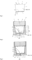
- the portion capsule 1 comprises a frustoconical capsule body 2 with a closed capsule base 3 and with a collar edge 5 arranged on its filling side 4, to which a lidding film 6 is welded or glued. Between the capsule base 3 and the lidding film 6, a cavity 100 is thus formed, preferably airtight and aroma-tight, which is filled with a powdered and granular beverage substance 101.
- the beverage substance 101 comprises, for example, coffee, cocoa, tea and/or milk powder (or granules).
- a filter element 7 is arranged, which is explained in more detail with reference to the following figures.
- the filter element 7 rests on the inner side 3a of the capsule base 3 and is firmly, i.e., materially connected, to the inner side 3a of the capsule body base 3.
- the filter element 7 is materially attached to the capsule base 3 along a circular ring only in an edge region 3' of the capsule base 3.
- the filter element comprises at least one layer of nonwoven fabric, in particular a nonwoven fabric made of fine polyester fibers.
- the fibers are particularly preferably thermally bonded to one another by means of a calender; for example, a plurality of extruded polyester fibers are arranged on top of and next to one another and then consolidated (flat calendered) by means of heated rollers.
- the nonwoven fabric comprises a random-fiber and/or fiber-oriented nonwoven fabric.
- FIG 2 is a portion capsule 1 according to the Figure 1 illustrated first embodiment of the present invention, wherein the portion capsule 1 in the Figure 2 is arranged in a closed brewing chamber 8.
- the brewing chamber 8 consists of a first brewing chamber element 9 and a second brewing chamber element 10, wherein the first brewing chamber element 9 is provided so as to be movable relative to the second brewing chamber element 10 or vice versa for the introduction of the portion capsule 1.
- a seal 11 is arranged between the two brewing chamber elements 9, 10.
- the first brewing chamber element 9 essentially consists of a closing piston 12 with piercing elements 13a, 13b for opening the lid film 6 of the portion capsule 1, a preparation liquid supply 14 and the seal 11.
- the second brewing chamber element 10 essentially consists of a brewing chamber bell 15 partially enclosing the portion capsule 1, with an opening pin 16 arranged on the bottom of the brewing chamber bell 15, which is provided with drainage grooves 17, and a beverage outlet 18.
- the brewing chamber 8 is in an open state (not shown), in which the first and second brewing chamber elements 9, 10 are spaced apart from one another to ensure that the portion capsule 1 is supplied, and the closed state shown, in which a preparation process for producing a beverage can be carried out using the portion capsule 1. In the closed state, the brewing chamber 8 is pressure-tight.
- the lid film 6 When transferring the brewing chamber 8 from the open state to the illustrated closed state, the lid film 6 is pierced by the piercing elements 13a, 13b, so that preparation liquid, in particular hot brewing water, is fed through the preparation liquid supply 14 under pressure into the cavity 100 of the portion capsule 1. Furthermore, when the brewing chamber 8 is closed, the capsule base 3 is perforated by the perforation means designed as an opening pin 16, so that an outlet opening 107 is created in the portion capsule 1, through which the produced beverage liquid can emerge from the portion capsule 1 in the direction of the beverage outlet 18. To assist in the drainage of the beverage liquid, the opening pin 16 preferably has the drainage grooves 17 on its outer surface.
- the base 3 of the portion capsule 1 located in the brewing chamber 9, 10 is pierced by the opening pin 16 of the second brewing comb element, but the filter element 7 located above the puncture point is slightly raised by the piercing tip 19 of the opening pin 16, but not pierced.
- This is achieved in particular in that the central region 7" is not materially connected to the capsule base 3, but the filter element 7 is materially connected to the capsule base 3 only in the edge region 3' of the capsule base 3, so that as a result of the mechanical contact with the tip of the opening mandrel 16 it is only lifted by the capsule base 3 and thus remains unperforated (i.e. is not perforated by the opening mandrel 16).
- the capsule base 3 and the filter element 7 remain in contact with one another and in particular are materially connected to one another, so that no beverage substance 101 gets around the filter element 7 into the beverage outlet 18.
- the opening mandrel 16 it is also possible for the opening mandrel 16 to pierce and/or pierce at least one layer of the filter element 7.
- FIG 3 a portion capsule 1 according to a second embodiment of the present invention is shown, wherein the second embodiment essentially corresponds to the one shown in Figure 2 illustrated first embodiment and the portion capsule 1 is also shown in a closed brewing chamber 8.
- the portion capsule base 3 has, in the piercing area of the opening mandrel 16, a bulge 21 directed towards an indentation 20 in the brewing chamber base 3a (the bulge 21 is thus directed in a direction opposite to the filling side 4), into which the opening mandrel 16 pierces without piercing the filter element 7. Lifting the filter element 7 from the capsule base 3 is therefore not necessary.
- the brewing chamber 8 is closed again after the portion capsule 1 has been introduced into the brewing chamber 8.
- the lidding film 6 of the portion capsule 1 is perforated by means of the piercing means 13a, 13b, and after the first and second brewing chamber elements 9, 10 have been brought together and sealed (by means of the seal 11), brewing water is made available via the liquid inlet 6.
- the opening mandrel 16 pierces an opening in the base 3 of the portion capsule 1.
- the filter element 7 located above the puncture point is matched in terms of its thickness and tear resistance to the penetration depth of the piercing tip 19 of the opening mandrel 16, so that the filter element 7 is not punctured.
- the filter element 7 lies above the bulge 21 of the capsule base 3, which lies in the indentation of the brewing bell base 23, and the opening pin 16 merely pierces the bulge 21 of the capsule base 3 and does not reach the filter element 7.
- the liquid for example, hot water when making coffee, then flows into the capsule 1. In the capsule, this liquid flows through the beverage substrate 101 and extracts and/or dissolves the substances required for beverage production from the beverage substrate 101.
- the flow of the liquid in the beverage substrate 101 is illustrated by the reference numeral 22.
- the resulting beverage then flows through the filter element 7 arranged between the beverage substrate 101 and the filter element 7 on the capsule base 3, which prevents components of the beverage substrate 101 from entering the resulting beverage in particle form and from passing through the opening pierced in the capsule base 3 by the opening mandrel 16 and through the drainage grooves 17 of the opening mandrel 16 into a collecting vessel, for example a cup or jug.
- a collecting vessel for example a cup or jug.
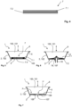
- Figure 4 shows a first embodiment of the filter element 7.
- This has, according to the invention, a first layer 7.1 and a second layer 7.2, which in the present case are each made of a fleece, i.e. a non-woven material.
- Both layers 7.1, 7.2 are connected to one another in a material-to-material manner, in particular by welding, preferably by ultrasonic welding. Both layers are provided here as circular disks.
- the connection is preferably made along a circular ring, which particularly preferably extends concentrically around the axis of rotation of the portion capsule.
- the two layers are preferably provided to be identical, but can also differ in terms of material, thickness and/or diameter.
- the two layers are first placed into the portion capsule, preferably as separate parts, and then the lower layer 7.2 is connected to the base 3 of the portion capsule.
- Filter element 7 is connected to the base 3 of the portion capsule by welding, in particular ultrasonic welding.
- the two layers 7.1 and 7.2 are connected to one another.
- the connection both between the filter element 7 and the capsule base 3 and between the two layers 7.1, 7.2 of the filter element to one another takes place along a circular ring.
- a sonotrode presses the two layers, preferably together, against the base of the portion capsule.
- the welding of the two layers to one another and the connection of the lower layer to the base of the portion capsule takes place at least essentially simultaneously.
- Figure 6 shows the piercing of the portion capsule by means of an opening pin 16, which first pierces the capsule base 3 and thereby provides an outlet for the beverage to be produced.
- the opening mandrel preferably pierces at least the lower layer of the filter element and at least partially pierces the upper layer 7.2. In particular, the distance between the two layers is increased locally, here in the central area of the filter element.
- Figure 7 shows another embodiment of the portion capsule according to the invention.
- a permanent opening is provided in the capsule base, which is closed here by a pull-off tab 109.
- This pull-off tab can be pierced by the opening mandrel or removed manually, for example by pulling it off, before the beverage is prepared.
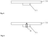
- Figure 8 shows a further embodiment of the filter 7, which is again provided in two layers, wherein the filter element in the present case has a first layer 7.2 consisting of a nonwoven fabric and a second layer 7.1 consisting of a felted material.
- the two layers are preferably bonded to one another, and most preferably, the flow-exposed area or the diameter of layer 7.1 is smaller than that of layer 7.2.
- the thickness of both layers can be the same or different.
- Figure 9 This diagram schematically shows the piercing of a portion capsule containing filter element 7. It is clearly visible that layer 7.1 is pierced, while layer 7.2 is only partially pierced. This ensures that no granules, for example, enter a beverage being produced.
Landscapes
- Engineering & Computer Science (AREA)
- Mechanical Engineering (AREA)
- Life Sciences & Earth Sciences (AREA)
- Biodiversity & Conservation Biology (AREA)
- Food Science & Technology (AREA)
- Apparatus For Making Beverages (AREA)
- Packging For Living Organisms, Food Or Medicinal Products That Are Sensitive To Environmental Conditiond (AREA)
- Non-Alcoholic Beverages (AREA)
- Tea And Coffee (AREA)
Description
- Die vorliegende Erfindung betrifft eine Portionskapsel zur Herstellung eines Getränks, aufweisend einen Kapselkörper mit einem Kapselboden und einer Einfüllseite, wobei zwischen dem Kapselboden und der Einfüllseite ein Hohlraum zur Aufnahme eines pulverförmigen oder flüssigen Getränkesubstrats ausgebildet ist und wobei zwischen dem Getränkesubstrat und dem Kapselboden ein Filterelement angeordnet ist.
- Solche Portionskapseln sind aus dem Stand der Technik allgemein bekannt. Beispielsweise sind in den Druckschiften
WO 2013/053757 A1 ,EP 1792850 B1 ,EP 1344722 A1 undUS 2003/0172813 A1 gattungsgemäße Portionskapseln zur Kaffee- und Espressozubereitung offenbart. - Derartige Portionskapseln zur Herstellung eines Getränkes sind bevorzugt kegelstumpfförmig oder zylindrisch geformt und werden beispielsweise aus einer tiefgezogenen Kunststofffolie oder im Kunststoffspritzverfahren hergestellt. Sie haben üblicherweise eine offene Einfüllseite mit einem Kragenrand, auf den eine Deckelfolie gesiegelt oder aufgeklebt wird, einen geschlossenen Kapselboden, wobei zwischen dem Getränkesubstrat und dem Kapselboden ein sich gegen den Kapselboden abstützendes Partikelsieb angeordnet ist. Diese Siebe sind entweder aus einem thermoplastischen Kunststoff gespritzt oder aus einer Kunstofffolie tiefgezogen oder geprägt.
- Für die Zubereitung eines Kaffeegetränkes wird die Portionskapsel in eine Brühkammer eines Zubereitungsgerätes eingebracht. Nach oder während des Schließvorganges der Brühkammer wird die Kapsel bevorzugt auf ihrer geschlossenen Bodenseite mittels eines in der Brühkammer angeordneten Öffnungsdornes geöffnet und nach dem Abdichten der Brühkammer wird die mit einer Verschlussfolie verschlossene Einfüllseite der Portionskapsel mittels Einstechmitteln angestochen. Anschließend wird Zubereitungsflüssigkeit, vorzugsweise heißes Wasser, unter Druck in die Portionskapsel gefördert. Die Zubereitungsflüssigkeit durchströmt das Getränkesubstrat und extrahiert und/oder löst die für die Getränkeherstellung benötigten Stoffe aus dem Getränkesubstrat aus. Für die Zubereitung eines Espresso wirkt zum Extrahieren der ätherischen Öle beispielsweise ein Brühwasserdruck von bis zu 20 bar auf das Kaffepulver. Dieser Druck wirkt ferner auch auf das zwischen dem Kaffeepulver und dem Kapselboden und vor dem eingestochenen Kapselauslauf liegende Partikelsieb ein.
- Nachteilig an den im Kunststoffspritzverfahren oder im Tiefzieh- oder Prägeverfahren hergestellten Sieben ist jedoch, dass für die Rückhaltung der Kaffeepartikel die Öffnung der Sieblöcher kleiner als die kleinsten Kaffeepartikel sein müssen. Da im Kaffeemahlverfahren zwangsläufig auch ein gewisser Staubanteil anfällt, ergibt sich bei zu großen Sieblöchern ein Kaffeepartikeldurchgang oder bei zu kleinen Sieblöchern, insbesondere bei hohen Drücken, ein Verstopfen der Siebe. Ferner sind unter den Sieben entsprechende, gegen den Kapselboden wirkende Abstützelemente erforderlich, um die Brühwasserdrücke von bis zu 20 bar aufzunehmen und eine Verformung der Siebe in Folge des hohen Brühwasserdrucks (zusammen mit einer hohen Brühwassertemperatur) zu verhindern. In nachteiliger Weise, erfordern diese Abstützelement insbesondere bei im Spritzgussverfahren hergestellten Siebanordnungen einen zusätzlichen Materialeinsatz, wodurch die Herstellungskosten steigen.
- Im Stand der Technik sind deshalb Portionskapseln mit Siebanordnungen bekannt, die diese Nachteile vermeiden sollen. In der
US 2778739 , derEP 1710173 A1 und derUS 5352765 sind Portionskapseln mit Siebanordnungen offenbart, die aus einem Siebträger mit relativ großen Durchgangsöffnungen bestehen, wobei diese Öffnungen mit einem Filtermaterial abgedeckt sind. Nachteil dieser Anordnungen ist, dass zur Darstellung derartiger Siebanordnungen Zusatzkosten für Material und die Fertigung entstehen, da sie aus einem stabilen Siebträger und dem auf dem Siebträger angeordneten Filtermaterial bestehen. - Sowohl bei Sieben mit Sieblöchern als auch bei Siebanordnungen mit einem zusätzlichen Filtermaterial muss sichergestellt werden, dass das durch die Siebanordnung tretende fertige Getränk zu einer Kapselausflussöffnung fließen kann, d.h. zwischen dem Kapselboden und der Siebanordnung muss ein Freiraum für den Getränkeablauf vorgesehen werden. Außerdem beanspruchen derartige Siebanordnungen einen eigenen Raumanteil in der Portionskapsel, was zu einer Vergrößerung des Kapselvolumens und damit zwangsläufig ebenfalls zu einem zusätzlichen Materialeinsatz führt.
- Aus dem Stand der Technik, beispielsweise der
WO2012/010317 sind außerdem ein Filter bekannt, die aus einem nicht gewebten Fasermaterial bekannt. Dieser Filter ist jedoch nicht für alle Kaffeeautomaten einsetzbar. - Es war deshalb die Aufgabe der vorliegenden Erfindung, eine Portionskapsel mit einer Filteranordnung zur Verfügung zu stellen, welche im Vergleich zum Stand der Technik kostengünstiger zu fertigen ist und bei welcher gleichzeitig die im Zusammenhang mit dem Stand der Technik aufgezeigten Nachteile vermieden werden.
- Gelöst wird diese Aufgabe mit einer Portionskapsel gemäß Patentanspruch 1.
- Im Vergleich zum Stand der Technik hat die erfindungsgemäße Portionskapsel den Vorteil, dass ein einfaches und kostengünstiges Filtervlies oder Filz als Filtersieb Verwendung findet. Ein aufwändiger Kunststoffspritzvorgang oder ein Tiefzieh- bzw. Prägeverfahren zur Herstellung der Siebe ist somit einsparbar. Die Herstellungskosten werden somit erheblich gesenkt. Zudem wird keine Stützstruktur benötigt, da sich das Vlies unmittelbar am Kapselboden abstützt. Im Vergleich zu den aus dem Stand der Technik bekannten Kunststofffiltern hat ein Filtervlies zudem den Vorteil, dass es eine deutlich größere Flüssigkeitseintrittsoberfläche aufweist. Ferner wird ein Flüssigkeitsquerfluss (parallel zur Haupterstreckungsebene der Filterebene) ermöglicht, wodurch ein besseres Durchmisch- und Abfließverhalten erzielt wird. Darüber hinaus hat sich gezeigt, dass sich bei der Verwendung eines Filtervlieses die Gefahr von Siebverstopfungen deutlich reduziert bzw. nahezu ausgeräumt ist. Überraschenderweise zeigt sich das Filtervlies sowohl bei einer Getränkezubereitung mit einer unter vergleichsweise niedrigen Druck stehenden Zubereitungsflüssigkeit, als auch bei einer Getränkezubereitung mit einer unter vergleichsweise hohen Druck stehenden Zubereitungsflüssigkeit als verstopfungsresistent. Ferner wird zuverlässig stets einen Flüssigkeitsquerfluss im Filtervlies aufrechterhalten und ein Abfluss der in das Filtervlies eintretenden Flüssigkeiten zu einer Abflussöffnung gewährleistet. Trotzdem bildet sich eine sogenannte "Crema", d.h. Schaum, auf dem Getränk, insbesondere dem Espresso, aus. Durch die Zweilagigkeit des Filterelements, kann eine Lage von einem Perforationselement durchstochen werden, ohne das nennenswerte Mengen an Granulat in das herzustellende Getränk gelangen.
- Die beiden Lagen sind vorzugsweise zunächst getrennt und werden bei dem Herstellungsprozess der Portionskapsel miteinander verbunden, insbesondere wenn sie mit dem Boden der Portionskapsel verbunden werden.
- Die Portionskapsel im Sinne der vorliegenden Erfindung umfasst eine vorzugsweise hermetisch dichte Portionskapsel. Dies bedeutet, dass das in der Portionskapsel befindliche Getränke- oder Lebensmittelpulver, beispielsweise Kaffeepulver, Suppenpulver oder Tee, vor dem Extraktionsvorgang im Wesentlichen aromadicht gegenüber der Umwelt verschlossen ist. Die Portionskapsel muss aber nicht hermetisch dicht sein, sondern kann auch, vor deren Verwendung in einer hermetisch dichten Verpackung vorgesehen sein, die dann, beispielsweise manuell geöffnet wird.
- Ein Vlies im Sinne der Erfindung ist eine ungeordnete, nicht gewebte Struktur aus Fasern, insbesondere Kunststofffasern. Ein Vlies im Sinne der Erfindung kann aus Kunststoff und/oder Naturfasern gefertigt sein. Ein Vlies kann beispielsweise aus Papier oder Papierähnliche Stoffen bestehen.
- Vorzugsweise sind beide Lagen aus einem Vliesmaterial hergestellt. Vorzugsweise sind beide Vlieslagen in Bezug auf Material, Dicke und/oder Durchmesser identisch. Die beiden Lagen sind vorzugsweise miteinander verbunden, insbesondere durch Schweißen, vorzugsweise Ultraschallschweißen miteinander verbunden. Vorzugsweise erfolgt der Verbund entlang eines Kreisrings, der sich besonders bevorzugt im oder in der Nähe des Randbereichs des Filters befindet.
- Gemäß einer bevorzugten Ausführungsform der vorliegenden Erfindung ist vorgesehen, dass das Vlies einen aus Kunststoff-Feinfasern, beispielsweise Polyester-Feinfasern, hergestellten Vliesstoff umfasst, welcher insbesondere ein Wirrfaser- und/oder faserorientierter-Vliesstoff ist. Das Vlies umfasst bevorzugt eine Massenbelegung (auch als Grammatur oder Flächengewicht bezeichnet) zwischen 40 und 250 Gramm pro Quadratmeter, besonders bevorzugt zwischen 80 und 120 Gramm pro Quadratmeter, und ganz besonders bevorzugt, von im Wesentlichen 100 Gramm pro Quadratmeter. Eine Lage des Filterelements weist bevorzugt eine Dicke zwischen 0,2 und 2,0 Millimetern, besonders bevorzugt zwischen 0,25 und 0,39 Millimetern, und ganz besonders bevorzugt, von im Wesentlichen 0,32 Millimetern auf. Das Vlies ist derart ausgebildet, dass die Luftdurchlässigkeit des Vlieses bei 100 Pascal bevorzugt zwischen 1000 und 3000 l/(m2s), besonders bevorzugt zwischen 1500 und 2500 (l/m2s) und ganz besonders bevorzugt, im Wesentlichen bei 2000 l/(m2s) liegt. Es hat sich in überraschender und nicht vorhersehbarer Weise gezeigt, dass mit derartigen Vliesstoffen optimale Ergebnisse hinsichtlich Extraktionseffizienz, Durchmisch- und Abfließverhalten, sowie Verstopfungsresistenz zu erzielen sind und sich trotzdem die "Crema" bildet. Trotzdem wird das Getränkesubstrat gut zurückgehalten auch wenn der Aufstechdorn das Filterelement an- und/oder durchsticht.
- Vorzugsweise wird das Vlies so auf dem Boden der Kapsel angeordnet dass es möglichst großflächig anliegt. Das Vlies an den Boden gesiegelt, insbesondere durch Ultraschall. Weiterhin bevorzugt wird das Vlies vor dessen Befestigung an der Kapsel, insbesondere dem Kapselboden, gespannt, um die Anlage an den Boden zu verbessern.
- Vorzugsweise überdeckt das Filterelement den Kapselboden vollständig oder nur teilweise.
- Beim Öffnen der Kapsel durch ein Perforationsmittel ist es vorteilhaft, wenn dieses das Vlies von dem Kapselboden wegbewegt und dabei spannt oder zusätzlich spannt. Dabei kann das Perforationsmittel in mindestens eine Lage des Vlieses eindringen und/oder mindestens eine Lage des Vlieses durchdringen.
- Gemäß einer weiteren Ausführungsform der vorliegenden Erfindung weist das Filterelement eine Lage Vlies und eine Lage mit einer Filzstruktur auf. Insbesondere handelt es sich dabei um eine Nadelfilzstruktur. Vorzugsweise besteht die Filzlage aus mindestens einer Filzstruktur und einer Trägerstruktur, insbesondere einer Gewebestruktur, wobei, besonders bevorzugt die Filzstruktur, zumindest einen Teilabschnitt des Volumens, die Trägerstruktur umfasst. Vorzugsweise erstreckt sich die Filzstruktur über der gesamten Querschnitt der Trägerstruktur. Vorzugsweise ist die Filzstruktur form- kraft und/oder stoffschlüssig mit der Trägerstruktur verbunden.
- Vorzugsweise wird die Oberfläche der Filzstruktur oder des Vlies behandelt, beispielsweise wärmebehandelt, um beispielsweise lose Fasern zu fixieren.
- Vorzugsweise wird die Lage, die die Filzstruktur aufweist mit der Vlieslage, insbesondere durch Stoffschluss, verbunden.
- Ein eine Trägerstruktur, insbesondere eine Gewebestruktur, und eine Filzstruktur aufweisendes Filterelement wird beispielsweise dadurch hergestellt, dass eine Gewebestruktur bestehend aus Längs- und Querfäden zur Verfügung gestellt wird. Für die Konstruktion eines Filzes, insbesondere eines Nadelfilzes, werden vorzugsweise Fasereinheiten ausgewählt von 0.8 - 7 dtex. Die Verbindung der Einzelfasern miteinander zu einem Filz und/oder dessen Verankerung in der Trägerstruktur findet vorzugsweise durch den Produktionsprozess des Vernadelns statt. Dabei werden Nadeln mit umgekehrten Widerhaken in das vorgelegte Faserpaket mit hoher Geschwindigkeit eingestochen und wieder herausgezogen. Durch die Widerhaken werden die Fasern über eine Vielzahl entstehender Schlaufen miteinander und/oder mit dem Trägergewebe verschlungen.
- Die Trägerstruktur aufweisend eine oder mehrere Filzstrukturen umfasst bevorzugt eine Massenbelegung (auch als Grammatur oder Flächengewicht bezeichnet) zwischen 100 und 1500 Gramm pro Quadratmeter, besonders bevorzugt zwischen 200 und 650 Gramm pro Quadratmeter, und ganz besonders bevorzugt, von im Wesentlichen 150 - 250 Gramm pro Quadratmeter insbesondere für die Herstellung von Tee aber auch für Kaffee, Espresso und dergleichen und 600 - 700 Gramm pro Quadratmeter für die Herstellung von Kaffee, Espresso oder dergleichen aber auch für Tee. Ganz besonders bevorzugt beträgt die Grammatur 1000 - 1300 Gramm pro Quadratmeter für die Herstellung von Kaffee, Espresso oder dergleichen aber auch für Tee. Die Lage mit der Filzstruktur weist bevorzugt eine Dicke zwischen 0,4 und 5,0 Millimetern, besonders bevorzugt zwischen 1,1 und 3,0 Millimetern, und ganz besonders bevorzugt, 1,2 - 1,4 Millimeter für die Herstellung von Tee und 2,6 - 3,0 für die Herstellung von Kaffee auf.
- Das Filterelement wird vorzugsweise in den Kapselkörper eingelegt und wird anschließend mit diesem und/oder der Seitenwand der Kapsel, insbesondere durch Schweißen, beispielsweise mit Ultraschall, verbunden, bevor das Getränkesubstrat in den Kapselkörper eingefüllt wird.
- Der Kapselkörper ist bevorzugt kegelstumpfförmig oder zylindrisch geformt und wird beispielsweise aus Kunststoff, einem Naturstoff und/oder einem biologisch abbaubaren Werkstoff aus einer tiefgezogenen Kunststofffolie oder im Kunststoffspritzverfahren hergestellt. Der Kapselkörper weist vorzugsweise auf der Einfüllseite einen Kragenrand auf, auf den eine Deckelfolie gesiegelt oder aufgeklebt ist. Alternativ ist denkbar, dass der Kapselkörper und ein Kapseldeckel mittels eines mechanischen Verfahrens miteinander verbunden sind. Der Boden der Portionskapsel ist vorzugsweise geschlossen und wird vorzugsweise erst in der Brühkammer mittels eines von außen auf den Portionskapselboden wirkenden Perforationsmittels zur Erzeugung einer Auslauföffnung perforiert. Alternativ wäre aber ebenso denkbar, dass der Boden der Portionskapsel bereits werksseitig mit einer Auslauföffnung versehen ist, welche mittels einer Dichtfolie vorzugsweise verschlossen ist. Die Dichtfolie ist dann beispielsweise mittels des Perforationsmittels perforierbar oder von Hand vom Kapselboden abziehbar. Das Filterelement ist vorzugsweise reißfest ausgebildet. Bei der Dichtfolie handelt es sich vorzugsweise um eine Kunststofffolie, die mindestens eine Barriereschicht, beispielsweise eine Metallschicht, insbesondere eine Aliminium-Schicht aufweist. Die Kunststofffolie weist vorzugsweise auf ihrer der Kapsel zugewandten Seite eine "Peel-Schicht" auf, um die Kunststofffolie vergleichsweise leicht von dem Kapselboden lösen zu können.
- Die Auslauföffnung ist vorzugsweise so groß vorgesehen, dass sie ein gegebenenfalls vorhandenes Perforationsmittel berührungsfrei aufnehmen kann. Besonders bevorzugt ist die Auslauföffnung so groß vorgesehen, dass an ihr, beim Ausströmen des fertiggestellten Getränkes kein nennenswerter Druckverlust entsteht, insbesondere dass es zu keiner nennenswerten Verwirbelung des fertiggestellten Getränkes kommt, der zu einem Gaseintrag in das Getränk und damit zur Schaumbildung führen könnte.
- Vorzugsweise weist die Portionskapsel einen Flüssigkeitsverteiler auf, der die einströmende Flüssigkeit umlenkt und über den Querschnitt der Portionskapsel verteilt.
- Vorzugsweise ist das Filterelement elastisch ausgebildet ist und zumindest in seinem Randbereich im Bereich des Kapselbodens angeordnet und/oder befestigt ist. Wenn der Kapselboden von einem äußeren Perforationsmittel durchstochen wird, kann das Filterelement bei einem Kontakt mit dem Perforationsmittel aufgrund seiner Elastizität derart nachgeben bzw. gedehnt werden, dass eine Perforation des Filterelements zumindest vermindert wird. Somit wird die Gefahr ausgeräumt, dass das Filterelement durch das Perforationsmittel vollständig perforiert wird und Getränkesubstanz ungefiltert aus der Portionskapsel gespült wird. Eine feste Beabstandung zwischen dem Filterelement und dem Kapselboden, wie sie aus dem Stand der Technik bekannt ist, ist nicht notwendig, da dieser Abstand durch das Perforationsmittel automatisch herbeigeführt wird. Auf diese Weise entsteht unterhalb des Filterelements ferner ein Sammelbecken für die durch das Filterelement hindurchtretende Getränkeflüssigkeit.
- Vorzugsweise wird mindestens eine Lage des Filterelements von dem Perforationsmittel gespannt, angestochen und/oder durchstochen.
- Gemäß einer weiteren Ausführungsform der vorliegenden Erfindung ist vorgesehen, dass das Filterelement den Kapselboden vollständig oder nur teilweise überdeckt. Insbesondere ist es ausreichend, wenn das Filterelement ausschließlich im Bereich der Perforierung bzw. im Bereich einer Auslassöffnung im Kapselboden angeordnet ist.
- Gemäß einer weiteren Ausführungsform der vorliegenden Erfindung ist vorgesehen, dass das Filterelement am Kapselboden befestigt ist, wobei das Filterelement stoffschlüssig am Kapselboden durch Siegeln befestigt ist. Vorteilhafterweise wird somit ein Verrutschen des Filterelements verhindert. Diese Befestigung erfolgt vorzugsweise durch Ultraschallschweißen.
- Gemäß einer weiteren Ausführungsform der vorliegenden Erfindung ist vorgesehen, dass das Filterelement in einem Randbereich des Kapselbodens am Kapselboden befestigt ist. Vorteilhafterweise wird somit ein Verrutschen des Filterelements verhindert und die Dichtwirkung zwischen Kapselkörper und Filterelement vergrößert, wobei aber gleichzeitig ein Anheben des Filterelements in seinem Zentralbereich weiterhin ermöglicht wird. Das Filterelement ist dabei vorzugsweise elastisch ausgebildet.
- Gemäß einer weiteren Ausführungsform der vorliegenden Erfindung ist vorgesehen, dass der Kapselboden eine Ausbuchtung in eine der Einfüllseite entgegengesetzte Richtung aufweist. Vorteilhafterweise dient die Ausbuchtung zur Aufnahme des Perforierungsmittels, so dass beim Einstechen des Perforierungsmittels in den Kapselboden der Kapselboden im Bereich der Ausbuchtung zwar perforiert wird, das Perforierungsmittel aber anschließend im Hohlraum der Ausbuchtung verbleibt. Vorzugsweise wird dabei zumindest eine Lage des Filterelements an- und/oder durchstochen. Vorzugsweise nimmt die Ausbuchtung das Filzelement zumindest teilweise auf.
- Gemäß einer weiteren Ausführungsform der vorliegenden Erfindung ist vorgesehen, dass das Filterelement sich nur in einem Zentralbereich vom Kapselboden abhebt und im Randbereich des Kapselbodens weiter am Kapselboden befestigt ist. Vorteilhafterweise wird somit ein Verrutschen des Filterelements verhindert und die Dichtwirkung zwischen Kapselkörper und Filterelement vergrößert, wobei aber gleichzeitig ein Anheben des Filterelements in seinem Zentralbereich weiterhin ermöglicht wird. Das Filterelement ist dabei vorzugsweise elastisch ausgebildet.
- Gemäß einer weiteren Ausführungsform weist der Kapselboden permanent eine Ausgangsöffnung auf, welche vorzugsweise mit einer Folie abgedichtet ist, wobei die Folie besonders bevorzugt eine Abziehlasche zum Abziehen der Folie von Hand aufweist. Eine Perforation des Kapselbodens mittels eines äußeren Perforationsmittel ist hierbei vorteilhafterweise nicht erforderlich. Vor dem Einlegen der Portionskapsel in die Brühkammer wird die Folie mittels der Abziehlasche einfach vom Kapselboden abgezogen und der Brühvorgang kann gestartet werden. Die Kombination einer vorgefertigten und somit vergleichsweise großen Ausgangsöffnung mit einem Filterelement aus einer oder mehreren Vlieslagen und/oder einer Lage mit einer Filzstruktur, insbesondere Nadelfilz hat den Vorteil, dass die Getränkeflüssigkeit nicht unter hohem Druck aus der Ausgangsöffnung herausfließt und somit die Schaumbildung ("Crema"), insbesondere bei der Herstellung von amerikanischem Kaffee oder Tee, verhindert wird.
- Vorzugsweise erfolgt die Verbindung des Filterelements mit dem Boden und die Verbindung zwischen den Lagen durch Schweißen, insbesondere Ultraschall-schweißen. Während der Verbindung der unteren, den Boden berührenden Lage mit dem Boden wird im Wesentlichen gleichzeitig auch ein Verbund der beiden Lagen untereinander erzeugt, vorzugsweise mit derselben Sonotrode.
- Ein weiterer Gegenstand der vorliegenden Erfindung ist ein Verfahren zur Herstellung eines Getränks mit der erfindungsgemäßen Portionskapsel, bei dem in einem ersten Verfahrensschritt die Portionskapsel bereitgestellt wird, in einem zweiten Verfahrensschritt der Kapselboden mittels eines äußeren Perforationsmittels perforiert wird, und in einem dritten Verfahrensschritt zumindest eine Lage des Filterelements zumindest teilweise vom Kapselboden beabstandet wird und/oder der Abstand zwischen den Lagen vergrößert wird.
- Die zu einem Gegenstand der vorliegenden Erfindung gemachten Ausführungen gelten für die anderen Gegenstände gleichermaßen und umgekehrt.
- Gemäß einer weiteren Ausführungsform der vorliegenden Erfindung ist vorgesehen, dass das Filterelement bei der Beabstandung des Zentralbereichs vom Kapselboden zumindest teilweise gedehnt wird. Auf diese Weise wird eine stoffschlüssige Befestigung des Randbereichs des Filterelements am Kapselboden ermöglicht, wobei sich trotzdem das Filterelement im Zentralbereich vom Kapselboden abheben kann. Hierdurch werden die Vorteile einer maximalen Dichtwirkung mit den Vorteilen des sich anhebenden Filterelements verknüpft. Alternativ oder zusätzlich wird der Abstand der beiden Lagen lokal, insbesondere im Zentralbereich vergrößert
- Ein weiterer Gegenstand der vorliegenden Erfindung ist die Verwendung einer Portionskapsel zur Herstellung eines Getränks, vorzugsweise zur Herstellung eines Kaffee-, Kakao-, Tee- und/oder Milchgetränks.
- Die zu einem Gegenstand der vorliegenden Erfindung gemachten Ausführungen gelten für die anderen Gegenstände gleichermaßen und umgekehrt.
- Ausführungsbeispiele der Erfindung sind in den Figuren dargestellt und in der nachfolgenden Beschreibung näher erläutert. Die Figuren sind lediglich beispielhaft beschrieben und schränken den allgemeinen Erfindungsgedanken nicht ein. Die Beschreibung gilt für alle Gegenstände der vorliegenden Erfindung gleichermaßen.
- Figur 1
- zeigt einen Längsschnitt durch eine Portionskapsel gemäß einer ersten Ausführungsform der vorliegenden Erfindung, die für die Zubereitung von Espresso eingerichtet ist.
- Figur 2
- zeigt einen Längsschnitt durch eine in einer geschlossenen Brühkammer liegende Portionskapsel gemäß der ersten Ausführungsform der vorliegenden Erfindung
- Figur 3
- zeigt einen Längsschnitt durch eine in einer geschlossenen Brühkammer liegende Portionskapsel gemäß einer zweiten Ausführungsform der vorliegenden Erfindung.
- Figuren 4
- zeigt eine erste Ausführungsform des Filterelements.
- Figuren 5
- zeigen schematisch die Herstellung der Portionskapsel
- Figuren 6
- zeigen schematische das Anstechen einer Portionskapsel.
- Figuren 7
- zeigen eine Portionskapsel mit einer verschlossenen Bodenöffnung.
- Figuren 8
- zeigt eine weitere Ausführungsform des Filters.
- Figur 9
- zeigt die Perforation des Filters gemäß
Figur 8 . - In den verschiedenen Figuren sind gleiche Teile stets mit den gleichen Bezugszeichen versehen und werden daher in der Regel auch jeweils nur einmal benannt bzw. erwähnt.
- In
Figur 1 ist eine erste Ausführungsform der erfindungsgemäßen Portionskapsel 1 dargestellt. Die Portionskapsel 1 umfasst einen kegelstumpfförmigen Kapselkörper 2 mit einem geschlossenen Kapselboden 3 und mit einem an seiner Einfüllseite 4 angeordneten Kragenrand 5, auf den eine Deckelfolie 6 aufgeschweißt oder geklebt ist. Zwischen dem Kapselboden 3 und der Deckelfolie 6 ist somit ein, vorzugsweise luft- und aromadicht verschlossener Hohlraum 100, ausgebildet, welcher mit einer pulver- und granulatförmigen Getränkesubstanz 101 gefüllt ist. Die Getränkesubstanz 101 umfasst dabei beispielsweise ein Kaffee-, Kakao-, Tee- und/oder Milchpulver (bzw. -granulat). Auf der Innenseite 3a des geschlossenen Kapselkörperbodens 3, d.h. innerhalb des Hohlraums 100, ist ein Filterelement 7angeordnet, das näher anhand der nachfolgenden Figuren erläutert wird. Das Filterelement 7 liegt auf der Innenseite 3a des Kapselbodens 3 auf und ist fest, d.h. stoffschlüssig, mit der Innenseite 3a des Kapselkörperbodens 3 verbunden. Das Filterelement 7 nur in einem Randbereich 3' des Kapselbodens 3 am Kapselboden 3 stoffschlüssig entlang eines Kreisrings befestigt. Das Filterelement umfasst mindestens eine Lage aus Vliesstoff, insbesondere ein aus Polyester-Feinfasern hergestellten Vliesstoff. Die Fasern werden besonders bevorzugt mittels eines Kalanders thermisch miteinander verbunden, beispielsweise werden eine Vielzahl von extrudierten Polyesterfasern aufeinander und nebeneinander angeordnet und anschließend mittels beheizten Walzen verfestigt (flach kalandriert). Der Vliesstoff umfasst einen Wirrfaser- und/oder faserorientierten-Vliesstoff. - In
Figur 2 ist eine Portionskapsel 1 gemäß der inFigur 1 illustrierten ersten Ausführungsform der vorliegenden Erfindung dargestellt, wobei die Portionskapsel 1 in derFigur 2 in einer geschlossenen Brühkammer 8 angeordnet ist. Die Brühkammer 8 besteht aus einem ersten Brühkammerelement 9 und einem zweiten Brühkammerelement 10, wobei das erste Brühkammerelement 9 zur Einführung der Portionskapsel 1 beweglich gegenüber dem zweiten Brühkammerelement 10 oder umgekehrt vorgesehen ist. Zwischen den beiden Brühkammerelementen 9, 10 ist eine Dichtung 11 angeordnet. Das erste Brühkammerelement 9 besteht im Wesentlichen aus einem Schließkolben 12 mit Einstechelementen 13a, 13b zur Öffnung der Deckelfolie 6 der Portionskapsel 1, einer Zubereitungsflüssigkeitszuführung 14 und der Dichtung 11. Das zweite Brühkammerelement 10 besteht im Wesentlichen aus einer die Portionskapsel 1 teilweise umschließenden Brühkammerglocke 15 mit einem am Boden der Brühkammerglocke 15 angeordneten Öffnungsdorn 16, der mit Ablaufrillen 17 versehen ist, und einem Getränkeablauf 18. Zur Aufnahme der Portionskapsel 1 befindet sich die Brühkammer 8 in einem nicht dargestellten geöffneten Zustand, in welchem das erste und das zweite Brühkammerelement 9, 10 voneinander beabstandet sind, um eine Zuführung der Portionskapsel 1 zu gewährleisten, und dem dargestellten geschlossenen Zustand, in welchem ein Zubereitungsvorgang zur Herstellung eines Getränks mittels der Portionskapsel 1 durchführbar ist. Im geschlossenen Zustand ist die Brühkammer 8 druckdicht verschlossen. Beim Überführen der Brühkammer 8 vom geöffneten Zustand in den abgebildeten geschlossenen Zustand wird die Deckelfolie 6 von den Einstechelementen 13a, 13b durchstochen, so dass Zubereitungsflüssigkeit, insbesondere heißes Brühwasser, durch die Zubereitungsflüssigkeitszuführung 14 unter Druck in den Hohlraum 100 der Portionskapsel 1 gelangt. Ferner wird beim Schließen der Brühkammer 8 der Kapselboden 3 von dem als Öffnungsdorn 16 ausgebildeten Perforationsmittel perforiert, so dass eine Ausgangsöffnung 107 in der Portionskapsel 1 erzeugt wird, durch welche die hergestellte Getränkeflüssigkeit aus der Portionskapsel 1 in Richtung des Getränkeablaufs 18 heraustreten kann. Zur Unterstützung der Ableitung der Getränkeflüssigkeit weist der Öffnungsdorn 16 auf seiner Mantelfläche vorzugsweise die Ablaufrillen 17 auf. In der Darstellung ist der Boden 3 der in der Brühkammer 9, 10 befindlichen Portionskapsel 1 von dem Öffnungsdorn 16 des zweiten Brühkammelementes durchstochen, aber das über der Einstichstelle liegende Filterelement 7 ist von der Einstechspitze 19 des Öffnungsdornes 16 leicht angehoben, jedoch nicht durchstochen. Dies wird insbesondere dadurch erreicht, dass der Zentralbereich 7" nicht stoffschlüssig mit dem Kapselboden 3 verbunden ist, sondern das Filterelement 7 lediglich im Randbereich 3' des Kapselbodens 3 stoffschlüssig mit dem Kapselboden 3 verbunden ist, so dass es in Folge des mechanischen Kontaktes mit der Spitze des Öffnungsdorns 16 lediglich vom Kapselboden 3 angehoben wird und somit unperforiert bleibt (d.h. nicht vom Öffnungsdorn 16 perforiert wird). Im Randbereich 3' des Kapselbodens 3 bzw. im Randbereich 7' des Filterelements 7 bleiben der Kapselboden 3 und das Filterelement 7 miteinander in Kontakt und insbesondere stoffschlüssig miteinander verbunden, so dass keine Getränkesubstanz 101 um das Filterelement 7 herum in den Getränkeablauf 18 gelangt. Es ist aber auch möglich, dass der Öffnungsdorn 16 mindestens eine Lage des Filterelements 7 an- und/oder durchsticht. - In
Figur 3 ist eine Portionskapsel 1 gemäß einer zweiten Ausführungsform der vorliegenden Erfindung dargestellt, wobei die zweite Ausführungsform im Wesentlichen der inFigur 2 illustrierten ersten Ausführungsform gleicht und die Portionskapsel 1 ebenfalls in einer geschlossenen Brühkammer 8 dargestellt ist. Im Unterschied zur ersten Ausführungsform weist der Portionskapselboden 3 im Einstechbereich des Öffnungsdornes 16 jedoch eine gegen eine Einbuchtung 20 im Brühkammerboden 3a gerichtete Ausbuchtung 21 auf (die Ausbuchtung 21 ist somit in eine der Einfüllseite 4 entgegengesetzte Richtung gerichtet), in die der Öffnungsdorn 16 einsticht, ohne dabei das Filterelement 7 zu durchstechen. Ein Abheben des Filterelements 7 vom Kapselboden 3 ist somit insbesondere nicht erforderlich. Zur Herstellung des Getränkes wird wiederum nach dem Einbringen der Portionskapsel 1 in die Brühkammer 8, die Brühkammer 8 geschlossen. Während des Schließvorganges wird die Deckelfolie 6 der Portionskapsel 1 mittels der Einstechmittel 13a, 13b perforiert und nach erfolgtem Zusammenführen und Abdichten des ersten und des zweiten Brühkammerelementes 9, 10 (mittels der Dichtung 11) wird Brühwasser über den Flüssigkeitseinlass 6 zur Verfügung gestellt. Ebenso sticht während des Schließvorganges der Brühkammer der Öffnungsdorn 16 eine Öffnung in den Boden 3 der Portionskapsel 1. Das über der Einstichstelle liegende Filterelement 7 ist in seiner Dicke und Reißfestigkeit auf die Eindringtiefe der Einstechspitze 19 des Öffnungsdornes 16 abgestimmt, so dass das Filterelement 7 nicht durchstoßen wird. Alternativ liegt das Filterelement 7 über der Ausbuchtung 21 des Kapselbodens 3, die in der Einbuchtung des Brühglockenbodens 23 liegt, und der Öffnungsdorn 16 sticht lediglich in die Ausbuchtung 21 des Kapselbodens 3 und gelangt nicht bis zum Filterelement 7. Sodann strömt die Flüssigkeit, bei der Herstellung von Kaffee beispielsweise heißes Wasser, in die Kapsel 1 ein. In der Kapsel durchströmt diese Flüssigkeit das Getränkesubstrat 101 und extrahiert und/oder löst die für die Getränkeherstellung benötigten Substanzen aus dem Getränkesubstrat 101 aus. Die Strömung der Flüssigkeit in dem Getränkesubstrat 101 ist durch das Bezugszeichen 22 illustriert. Danach strömt das resultierende Getränk durch das zwischen dem Getränkesubstrat 101 und das auf dem Kapselboden 3 angeordnete Filterelement 7, welches verhindert, dass Bestandteile des Getränkesubstrates 101 partikelförmig in das resultierende Getränk gelangen und über die von dem Öffnungsdorn 16 in den Kapselboden 3 gestochene Öffnung und über die Ablaufrillen 17 des Öffnungsdornes 16 weiter in ein Auffanggefäß, beispielsweise eine Tasse oder Kanne, gelangen. -
Figur 4 zeigt eine erste Ausführungsform des Filterelements 7. Dieses weist erfindungsgemäß eine erste Lage 7.1 und eine zweite Lage 7.2 auf, die in dem vorliegenden Fall jeweils aus einem Vlies, d.h. einem nicht gewebten Material gefertigt sind. Beide Lagen 7.1, 7.2 sind hier stoffschlüssig, insbesondere durch Schweißen, vorzugsweise durch Ultraschall-Schweißen miteinander verbunden. Beide Lagen sind hier als Kreisscheiben vorgesehen. Die Verbindung erfolgt vorzugsweise entlang eines Kreisrings, der sich besonders bevorzugt konzentrisch um die Rotationsachse der Portionskapsel erstreckt. Die beiden Lagen sind vorzugsweise identisch vorgesehen, können sich aber auch hinsichtlich dem Material, der Dicke und oder dem Durchmesser unterscheiden. - Wie insbesondere
Figur 5 entnommen werden kann, werden die beiden Lagen zunächst vorzugsweise als separate Teile in die Portionskapsel eingelegt und dann wird die untere Lage 7.2 mit dem Boden 3 der Portionskapsel verbunden Filterelement 7 am Boden 3 der Portionskapsel durch Schweißen, insbesondere Ultraschall-Schweißen verbunden. Gleichzeitig werden die beiden Lagen 7.1 und 7.2 dabei miteinander verbunden. Die Verbindung sowohl zwischen dem Filterelement 7 und dem Kapselboden 3 als auch zwischen den beiden Lagen 7.1, 7.2 des Filterelements untereinander erfolgt entlang eines Kreisrings. Eine Sonotrode drückt die beiden Lagen vorzugsweise zusammen und dabei gegen den Boden der Portionskapsel. Dabei erfolgt die Verschweißung der beiden Lagen untereinander und die Verbindung der unteren Lage mit dem Boden der Portionskapsel zumindest im Wesentlichen gleichzeitig. -
Figur 6 zeigt das Anstechen der Portionskapsel mittels eines Öffnungsdorns 16, der zunächst den Kapselboden 3 durchsticht und dadurch einen Ablauf für das herzustellende Getränk zur Verfügung stellt. Wie der Darstellung gemäßFigur 6 entnommen werden kann, durchsticht der Öffnungsdorn vorzugsweise zumindest die untere Lage des Filterelements und sticht die obere Lage 7.2 zumindest an. Insbesondere wird der Abstand zwischen den beiden Lagen lokal, hier im Zentralbereich des Filterelements, vergrößert. -
Figur 7 zeigt eine weitere Ausführungsform der erfindungsgemäßen Portionskapsel. In dem vorliegenden Fall ist in dem Kapselboden eine permanente Öffnung vorgesehen, die hier durch eine Abziehlasche 109 verschlossen ist. Diese Abziehlasche kann von dem Öffnungsdorn durchstochen oder vor der Herstellung des Getränks manuell, beispielsweise durch Abziehen, entfernt werden. -
Figur 8 zeigt eine weitere Ausführungsform des Filters 7, der wiederum zweilagig vorgesehen ist, wobei das Filterelement in dem vorliegenden Fall eine erste Lage 7.2, bestehend aus einem Vliesstoff, und eine zweite Lage 7.1, bestehend aus einem gefilzten Material, aufweist. Die beiden Lagen sind vorzugsweise stoffschlüssig miteinander verbunden und ganz besonders bevorzugt ist die angeströmte Fläche oder der Durchmesser der Lage 7.1 kleiner im Vergleich zu der Lage 7.2. Die Dicke beider Lagen kann gleich oder unterschiedlich sein.Figur 9 zeigt schematisch das Anstechen einer Portionskapsel, in der sich das Filterelement 7 befindet. Es ist deutlich zu erkennen, dass die Lage 7.1 durch- und die Lage 7.2 nur angestochen wird. Dadurch ist sichergestellt, dass kein Granulat beispielsweise in ein herzustellendes Getränk gelangt. -
- 1
- Portionskapsel
- 2
- Kapselkörper
- 3
- Kapselboden
- 3a
- Kapselboden-Innenseite
- 3'
- Randbereich des Kapselbodens
- 4
- Einfüllseite
- 5
- Kragenrand
- 6
- Deckelfolie
- 7
- Filterelement
- 7'
- Randbereich des Filterelements
- 7"
- Zentralbereich des Filterelements
- 7.1
- Filzstruktur, Nadelfilzstruktur
- 7.2
- Trägerstruktur
- 7.3
- Filzstruktur, Nadelfilzstruktur
- 8
- Brühkammer
- 9
- Erstes Brühkammerelement
- 10
- Zweites Brühkammerelement
- 11
- Dichtung
- 12
- Schließkolben
- 13a
- Einstechelement
- 13b
- Einstechelement
- 14
- Zubereitungsflüssigkeitszufuhr
- 15
- Brühglocke
- 16
- Öffnungsdorn
- 17
- Auslaufrillen
- 18
- Ablauf
- 19
- Einstechspitze
- 20
- Einbuchtung
- 21
- Ausbuchtung
- 22
- Zubereitungsflüssigkeitsfluss
- 23
- Brühglockenboden
- 100
- Hohlraum
- 101
- Getränkesubstrat
- 102
- Seitenwandbereich
- 103
- Befestigung des Filters 7, Scheißung
- 103'
- Gewellter oder gefalteter Bereich
- 104
- Sollbruchstelle
- 105
- Schwächungslinien
- 106
- Zentraler Punkt
- 107
- Ausgangsöffnung
- 108
- Folie
- 109
- Abziehlasche
Claims (14)
- Portionskapsel (1) zur Herstellung eines Getränks aufweisend einen Kapselkörper (2) mit einem Kapselboden (3) und einer Einfüllseite (4), wobei zwischen dem Kapselboden (3) und der Einfüllseite (4) ein Hohlraum (100) zur Aufnahme eines pulverförmigen oder flüssigen Getränkesubstrats (101) ausgebildet ist und wobei zwischen dem Getränkesubstrat (101) und dem Kapselboden (3) ein Filterelement (7) angeordnet ist, das als Filtersieb Verwendung findet, wobei das Filterelement (7) aus einem nicht gewebtem Material vorgesehen ist, welches im Bereich des Kapselbodens (3) angeordnet und an den Kapselboden gesiegelt ist, wobei das Filterelement aus zwei Lagen (7.1, 7.2) und davon mindestens eine Lage aus Vlies vorgesehen ist, dadurch gekennzeichnet, dass die beiden Lagen (7.1, 7.2) durch eine Siegelung miteinander verbunden sind und die Siegelung lokal als Kreisring vorgesehen ist.
- Portionskapsel (1) nach Anspruch 1, dadurch gekennzeichnet, dass beide Lagen (7.1, 7.2) aus einem Vlies vorgesehen sind.
- Portionskapsel (1) nach Anspruch 1, dadurch gekennzeichnet, dass das Filterelement (7) aus einer Vlies- (7.1) und einer Filzlage (7.2) vorgesehen ist.
- Portionskapsel (1) nach Anspruch 3, dadurch gekennzeichnet, dass die Filzlage (7.2) eine geringere angeströmte Fläche aufweist als die Vlieslage (7.1).
- Portionskapsel (1) nach einem der Ansprüche 1 - 4, dadurch gekennzeichnet, dass das Vlies einen aus Polyester-Feinfasern hergestellten Vliesstoff umfasst und/oder dass das Vlies eine Massenbelegung zwischen 50 und 150 Gramm pro Quadratmeter, bevorzugt zwischen 80 und 120 Gramm pro Quadratmeter und besonders bevorzugt 100 Gramm pro Quadratmeter aufweist und/oder dass das Vlies eine Dicke zwischen 0,2 und 0,8 Millimetern, bevorzugt zwischen 0,25 und 0,39 Millimetern und besonders bevorzugt von im Wesentlichen 0,32 Millimetern aufweist und/oder dass das Vlies eine Luftdurchlässigkeit bei einem Druck von 100 Pascal zwischen 1000 und 3000 I/(m 2 s), bevorzugt zwischen 1500 und 2500 (I/m 2 s) und besonders bevorzugt im Wesentlichen bei 2000 I/(m 2 s) aufweist.
- Portionskapsel (1) nach einem der vorhergehenden Ansprüche, dadurch gekennzeichnet, dass das Filterelement (7) an den Boden der Kapsel ultraschallgesiegelt und vorzugsweise gespannt ist.
- Portionskapsel (1) nach einem der vorhergehenden Ansprüche, dadurch gekennzeichnet, dass das Filterelement (7) den Kapselboden (3) vollständig oder nur teilweise überdeckt.
- Portionskapsel (1) nach einem der vorhergehenden Ansprüche, dadurch gekennzeichnet, dass der Kapselboden (3) eine Ausbuchtung (21) in eine der Einfüllseite (4) entgegengesetzte Richtung (103) aufweist.
- Portionskapsel (1) nach einem der vorhergehenden Ansprüche, dadurch gekennzeichnet, dass das Filterelement (7) derart ausgebildet ist, dass bei einer Perforation des Kapselbodens (3) durch ein äußeres Perforationsmittel (16) zumindest teilweise ein Abheben des Filterelements (7) vom Kapselboden (3) erfolgt und/oder dass das Perforationsmittel zumindest eine Lage (7.1, 7.2) des Filters (7) perforiert.
- Portionskapsel (1) nach Anspruch 9, dadurch gekennzeichnet, dass das Filterelement (7) sich nur in einem Zentralbereich (7") vom Kapselboden (3) abhebt und im Randbereich (3') des Kapselbodens (3) weiter auf dem Kapselboden (3) aufliegt oder am Kapselboden (3) befestigt ist.
- Portionskapsel (1) nach Anspruch 9 oder 10, dadurch gekennzeichnet, dass das Perforationsmittel beide Lagen (7.1, 7.2) durch- und/oder ansticht.
- Portionskapsel (1) nach einem der voranstehenden Ansprüche, dadurch gekennzeichnet, dass das Filterelement (7) derart ausgebildet ist, dass bei einer Perforation des Kapselbodens (3) durch ein äußeres Perforationsmittel (16) das Filterelement (7) sich in seinem Zentralbereich (7") vom Kapselboden (3) abhebt und/oder sich der Abstand zwischen den Lagen (7.1., 7.2) verändert.
- Portionskapsel (1) nach einem der vorhergehenden Ansprüche, dadurch gekennzeichnet, dass der Kapselboden (3) eine Ausgangsöffnung (107) aufweist, welche vorzugsweise mit einer Folie (108) abgedichtet ist, wobei die Folie (108) besonders bevorzugt eine Abziehlasche (109) zum Abziehen der Folie von Hand aufweist.
- Verfahren zur Herstellung eines Getränks mit einer Portionskapsel (1) nach einem der Ansprüche 1-13, dadurch gekennzeichnet, dass in einem ersten Verfahrensschritt die Portionskapsel (1) bereitgestellt wird, dass in einem zweiten Verfahrensschritt der Kapselboden (3) mittels eines äußeren Perforationsmittels (16) perforiert wird, und dass in einem dritten Verfahrensschritt der Abstand zwischen den Lagen (7.1, 7.2) lokal vergrößert wird.
Applications Claiming Priority (2)
| Application Number | Priority Date | Filing Date | Title |
|---|---|---|---|
| DE102014105486 | 2014-04-17 | ||
| PCT/EP2015/058289 WO2015158838A1 (de) | 2014-04-17 | 2015-04-16 | Portionskapsel und verfahren zur herstellung eines getränks mit einer portionskapsel |
Publications (3)
| Publication Number | Publication Date |
|---|---|
| EP3131833A1 EP3131833A1 (de) | 2017-02-22 |
| EP3131833B1 EP3131833B1 (de) | 2018-06-27 |
| EP3131833B2 true EP3131833B2 (de) | 2025-06-11 |
Family
ID=52997424
Family Applications (1)
| Application Number | Title | Priority Date | Filing Date |
|---|---|---|---|
| EP15717861.7A Active EP3131833B2 (de) | 2014-04-17 | 2015-04-16 | Portionskapsel und verfahren zur herstellung eines getränks mit einer portionskapsel |
Country Status (17)
| Country | Link |
|---|---|
| US (1) | US20170036857A1 (de) |
| EP (1) | EP3131833B2 (de) |
| JP (1) | JP6349457B2 (de) |
| KR (1) | KR20160146859A (de) |
| CN (1) | CN106232502A (de) |
| AR (1) | AR100100A1 (de) |
| AU (1) | AU2015248756B2 (de) |
| BR (1) | BR112016024081A2 (de) |
| CA (1) | CA2945550A1 (de) |
| IL (1) | IL248289A0 (de) |
| MX (1) | MX2016013407A (de) |
| PH (1) | PH12016502020A1 (de) |
| RU (1) | RU2657689C9 (de) |
| SG (1) | SG11201608479SA (de) |
| TW (1) | TW201545957A (de) |
| WO (1) | WO2015158838A1 (de) |
| ZA (1) | ZA201607021B (de) |
Families Citing this family (25)
| Publication number | Priority date | Publication date | Assignee | Title |
|---|---|---|---|---|
| US10722066B2 (en) * | 2010-12-04 | 2020-07-28 | Adrian Rivera | Windowed single serving brewing material holder |
| US11832755B2 (en) * | 2007-07-13 | 2023-12-05 | Adrian Rivera | Brewing material container for a beverage brewer |
| US10071851B2 (en) | 2010-07-12 | 2018-09-11 | Robert Bao Vu | Apparatus and products for producing beverages, and methods for making and using same |
| CN105996782A (zh) * | 2010-07-22 | 2016-10-12 | K-Fee系统股份有限公司 | 具有标识符的分配胶囊 |
| DE102012105282A1 (de) * | 2012-06-18 | 2013-12-19 | K-Fee System Gmbh | Portionskapsel und Verfahren zur Herstellung eines Getränks mit einer Portionskapsel |
| NL2014628B1 (nl) * | 2015-01-08 | 2017-12-22 | Stas I P B V | Houder met daarin een te extraheren product, alsmede werkwijze voor het vervaardigen van de houder. |
| DK3368447T3 (da) | 2015-10-27 | 2020-05-04 | Douwe Egberts Bv | Kapsel, system og fremgangsmåde til tilberedning af en drikkevare |
| DE102016201498B4 (de) * | 2016-02-01 | 2017-08-17 | Norbert Kuhl | Sauerstoffdichter lebensmittelbehälter |
| NL2017277B1 (en) | 2016-08-03 | 2018-02-14 | Douwe Egberts Bv | Apparatus and method for preparing a beverage and system comprising the apparatus and an exchangeable capsule |
| NL2017280B1 (en) | 2016-08-03 | 2018-02-14 | Douwe Egberts Bv | System for preparing a beverage |
| NL2017278B1 (en) | 2016-08-03 | 2018-02-14 | Douwe Egberts Bv | System, apparatus, method, capsule and kit of capsules for preparing a beverage |
| NL2017283B1 (en) | 2016-08-03 | 2018-02-14 | Douwe Egberts Bv | System and apparatus for preparing a beverage |
| NL2017282B1 (en) | 2016-08-03 | 2018-02-14 | Douwe Egberts Bv | System for preparing a beverage |
| NL2017281B1 (en) | 2016-08-03 | 2018-02-14 | Douwe Egberts Bv | System for preparing a beverage |
| NL2017285B1 (en) | 2016-08-03 | 2018-02-14 | Douwe Egberts Bv | System, apparatus, method, capsule and kit of capsules for preparing a beverage |
| NL2019218B1 (en) | 2016-08-03 | 2018-07-06 | Douwe Egberts Bv | Capsule, system and use of the system for preparing double beverages like a double espresso, a double lungo and a double ristretto |
| NL2017284B1 (en) | 2016-08-03 | 2018-02-14 | Douwe Egberts Bv | System and method for preparing a beverage field and background |
| NL2017279B1 (en) | 2016-08-03 | 2018-02-14 | Douwe Egberts Bv | System for preparing a beverage |
| IT201600082459A1 (it) * | 2016-08-04 | 2018-02-04 | Bisio Progetti Spa | Capsula per la preparazione di bevande ad infusione e solubili |
| CN109077617A (zh) * | 2018-04-06 | 2018-12-25 | 彩盛咖啡茶(北京)有限公司 | 封闭容器和利用封闭容器萃取饮品的方法 |
| US20240140047A1 (en) * | 2018-11-12 | 2024-05-02 | Opem S.P.A. | Method and device for manufacturing containers adapted to contain a food substance for the preparation of beverages |
| NL2022190B1 (en) | 2018-12-12 | 2020-07-03 | Douwe Egberts Bv | Air purge groove |
| US11805934B1 (en) * | 2020-10-21 | 2023-11-07 | Adrian Rivera | Brewing material lid and container for a beverage brewer |
| WO2022192783A1 (en) * | 2021-03-12 | 2022-09-15 | Nexe Innovations Inc. | Beverage pod |
| KR102780961B1 (ko) * | 2021-11-30 | 2025-03-12 | 김병규 | 나선형 구조를 갖는 커피캡슐 |
Citations (2)
| Publication number | Priority date | Publication date | Assignee | Title |
|---|---|---|---|---|
| EP1344724A1 (de) † | 2002-03-14 | 2003-09-17 | Robert Hale | Kartusche für Getränke und Filter dafür |
| WO2010112353A1 (en) † | 2009-03-31 | 2010-10-07 | Nestec S.A. | Capsule with filter for preparing a liquid nutritional or food composition and related beverage production system |
Family Cites Families (17)
| Publication number | Priority date | Publication date | Assignee | Title |
|---|---|---|---|---|
| US2778739A (en) | 1954-07-16 | 1957-01-22 | Sealpak Corp | Package for beverage infusion material |
| TW305850B (de) | 1992-11-17 | 1997-05-21 | Shell Int Research | |
| DE20100166U1 (de) * | 2001-01-05 | 2001-03-29 | Melitta Haushaltsprodukte GmbH & Co. KG, 32427 Minden | Portionspackung zur Herstellung eines Brühgetränkes |
| DE10211327B4 (de) | 2002-03-14 | 2015-09-24 | Caffitaly System S.P.A. | Portionenkapsel mit einer partikelförmigen mittels Wasser extrahierbaren Substanz zur Herstellung eines Getränks |
| US20040045443A1 (en) * | 2002-06-19 | 2004-03-11 | Lazaris Nicholas G. | Disposable beverage filter package |
| US7444926B2 (en) * | 2003-09-09 | 2008-11-04 | Nottingham John R | Apparatus for brewing and method for making the same |
| DE102005016297A1 (de) * | 2005-04-08 | 2006-10-12 | Tchibo Gmbh | Portionskapsel |
| DE102005058336A1 (de) | 2005-12-02 | 2007-06-06 | Tchibo Gmbh | Portionskapsel |
| US9750370B2 (en) * | 2009-05-29 | 2017-09-05 | Keurig Green Mountain, Inc. | Cartridge with filter guard |
| CN105996782A (zh) | 2010-07-22 | 2016-10-12 | K-Fee系统股份有限公司 | 具有标识符的分配胶囊 |
| DE102011012881A1 (de) * | 2010-09-22 | 2012-03-22 | Krüger Gmbh & Co. Kg | Portionskapsel und Verfahren zur Herstellung eines Getränks mit einer Portionskapsel |
| US8895090B2 (en) * | 2010-09-22 | 2014-11-25 | K-Fee System Gmbh | Portion capsule and method for producing the same |
| DE102011115833A1 (de) * | 2011-10-13 | 2013-04-18 | K-Fee System Gmbh | Portionskapsel zur Herstellung eines Getränks mit einer Portionskapsel |
| DE102012105282A1 (de) * | 2012-06-18 | 2013-12-19 | K-Fee System Gmbh | Portionskapsel und Verfahren zur Herstellung eines Getränks mit einer Portionskapsel |
| CN104379470A (zh) * | 2012-06-29 | 2015-02-25 | K-Fee系统股份有限公司 | 包含可提供机械、可读标示塑料薄膜的单杯胶囊 |
| PT2867143T (pt) * | 2012-06-29 | 2018-10-16 | K Fee System Gmbh | Cápsula de dose individual com uma identificação na face interna de uma membrana de fecho |
| DE102012109186A1 (de) * | 2012-09-27 | 2014-03-27 | K-Fee System Gmbh | Portionskapsel mit einem durch Siegeln verbundenen Filterelement |
-
2015
- 2015-04-16 MX MX2016013407A patent/MX2016013407A/es unknown
- 2015-04-16 CN CN201580019739.XA patent/CN106232502A/zh active Pending
- 2015-04-16 TW TW104112198A patent/TW201545957A/zh unknown
- 2015-04-16 KR KR1020167032099A patent/KR20160146859A/ko not_active Withdrawn
- 2015-04-16 RU RU2016144965A patent/RU2657689C9/ru not_active IP Right Cessation
- 2015-04-16 CA CA2945550A patent/CA2945550A1/en not_active Abandoned
- 2015-04-16 BR BR112016024081A patent/BR112016024081A2/pt not_active Application Discontinuation
- 2015-04-16 US US15/303,859 patent/US20170036857A1/en not_active Abandoned
- 2015-04-16 EP EP15717861.7A patent/EP3131833B2/de active Active
- 2015-04-16 SG SG11201608479SA patent/SG11201608479SA/en unknown
- 2015-04-16 WO PCT/EP2015/058289 patent/WO2015158838A1/de not_active Ceased
- 2015-04-16 AR ARP150101153A patent/AR100100A1/es unknown
- 2015-04-16 JP JP2017504271A patent/JP6349457B2/ja active Active
- 2015-04-16 AU AU2015248756A patent/AU2015248756B2/en not_active Ceased
-
2016
- 2016-10-10 IL IL248289A patent/IL248289A0/en unknown
- 2016-10-11 PH PH12016502020A patent/PH12016502020A1/en unknown
- 2016-10-12 ZA ZA2016/07021A patent/ZA201607021B/en unknown
Patent Citations (2)
| Publication number | Priority date | Publication date | Assignee | Title |
|---|---|---|---|---|
| EP1344724A1 (de) † | 2002-03-14 | 2003-09-17 | Robert Hale | Kartusche für Getränke und Filter dafür |
| WO2010112353A1 (en) † | 2009-03-31 | 2010-10-07 | Nestec S.A. | Capsule with filter for preparing a liquid nutritional or food composition and related beverage production system |
Also Published As
| Publication number | Publication date |
|---|---|
| TW201545957A (zh) | 2015-12-16 |
| US20170036857A1 (en) | 2017-02-09 |
| KR20160146859A (ko) | 2016-12-21 |
| EP3131833B1 (de) | 2018-06-27 |
| JP6349457B2 (ja) | 2018-06-27 |
| RU2657689C2 (ru) | 2018-06-14 |
| CA2945550A1 (en) | 2015-10-22 |
| AU2015248756A1 (en) | 2016-11-03 |
| SG11201608479SA (en) | 2016-11-29 |
| JP2017517357A (ja) | 2017-06-29 |
| RU2016144965A (ru) | 2018-05-17 |
| WO2015158838A1 (de) | 2015-10-22 |
| AR100100A1 (es) | 2016-09-07 |
| RU2016144965A3 (de) | 2018-05-17 |
| CN106232502A (zh) | 2016-12-14 |
| BR112016024081A2 (pt) | 2017-08-15 |
| MX2016013407A (es) | 2017-02-15 |
| EP3131833A1 (de) | 2017-02-22 |
| ZA201607021B (en) | 2018-11-28 |
| PH12016502020A1 (en) | 2017-01-09 |
| RU2657689C9 (ru) | 2018-07-16 |
| AU2015248756B2 (en) | 2018-01-18 |
| IL248289A0 (en) | 2016-11-30 |
Similar Documents
| Publication | Publication Date | Title |
|---|---|---|
| EP3131833B2 (de) | Portionskapsel und verfahren zur herstellung eines getränks mit einer portionskapsel | |
| EP3336013B1 (de) | Portionskapsel und verfahren zur herstellung eines getränks mit einer portionskapsel | |
| EP2861508B9 (de) | Portionskapsel und verfahren zur herstellung eines getränks mit einer portionskapsel | |
| EP2961671B1 (de) | Portionskapsel und verfahren zur herstellung eines getränks mit einer portionskapsel | |
| EP3418215B1 (de) | Portionskapsel mit einem kalandrierten faserartigem material | |
| EP2625120B1 (de) | Portionskapsel zur herstellung eines getränks mit einer portionskapsel | |
| EP3261957B1 (de) | Portionskapsel mit einem durch siegeln verbundenen filterelement | |
| WO2014090567A1 (de) | Portionskapsel und verfahren zur herstellung eines getränks mit einer portionskapsel | |
| EP3307647B1 (de) | Portionskapsel mit einem dreilagigen vlies | |
| EP3157844A1 (de) | System zur herstellung eines teegetränks | |
| EP3310693B1 (de) | Portionskapsel und verfahren zur herstellung eines getränks mit einer portionskapsel |
Legal Events
| Date | Code | Title | Description |
|---|---|---|---|
| STAA | Information on the status of an ep patent application or granted ep patent |
Free format text: STATUS: THE INTERNATIONAL PUBLICATION HAS BEEN MADE |
|
| PUAI | Public reference made under article 153(3) epc to a published international application that has entered the european phase |
Free format text: ORIGINAL CODE: 0009012 |
|
| STAA | Information on the status of an ep patent application or granted ep patent |
Free format text: STATUS: REQUEST FOR EXAMINATION WAS MADE |
|
| 17P | Request for examination filed |
Effective date: 20161117 |
|
| AK | Designated contracting states |
Kind code of ref document: A1 Designated state(s): AL AT BE BG CH CY CZ DE DK EE ES FI FR GB GR HR HU IE IS IT LI LT LU LV MC MK MT NL NO PL PT RO RS SE SI SK SM TR |
|
| AX | Request for extension of the european patent |
Extension state: BA ME |
|
| DAV | Request for validation of the european patent (deleted) | ||
| DAX | Request for extension of the european patent (deleted) | ||
| GRAP | Despatch of communication of intention to grant a patent |
Free format text: ORIGINAL CODE: EPIDOSNIGR1 |
|
| STAA | Information on the status of an ep patent application or granted ep patent |
Free format text: STATUS: GRANT OF PATENT IS INTENDED |
|
| INTG | Intention to grant announced |
Effective date: 20180313 |
|
| GRAS | Grant fee paid |
Free format text: ORIGINAL CODE: EPIDOSNIGR3 |
|
| GRAA | (expected) grant |
Free format text: ORIGINAL CODE: 0009210 |
|
| STAA | Information on the status of an ep patent application or granted ep patent |
Free format text: STATUS: THE PATENT HAS BEEN GRANTED |
|
| AK | Designated contracting states |
Kind code of ref document: B1 Designated state(s): AL AT BE BG CH CY CZ DE DK EE ES FI FR GB GR HR HU IE IS IT LI LT LU LV MC MK MT NL NO PL PT RO RS SE SI SK SM TR |
|
| REG | Reference to a national code |
Ref country code: GB Ref legal event code: FG4D Free format text: NOT ENGLISH |
|
| REG | Reference to a national code |
Ref country code: AT Ref legal event code: REF Ref document number: 1012105 Country of ref document: AT Kind code of ref document: T Effective date: 20180715 |
|
| REG | Reference to a national code |
Ref country code: IE Ref legal event code: FG4D Free format text: LANGUAGE OF EP DOCUMENT: GERMAN |
|
| REG | Reference to a national code |
Ref country code: DE Ref legal event code: R096 Ref document number: 502015004839 Country of ref document: DE |
|
| REG | Reference to a national code |
Ref country code: NL Ref legal event code: FP |
|
| PG25 | Lapsed in a contracting state [announced via postgrant information from national office to epo] |
Ref country code: BG Free format text: LAPSE BECAUSE OF FAILURE TO SUBMIT A TRANSLATION OF THE DESCRIPTION OR TO PAY THE FEE WITHIN THE PRESCRIBED TIME-LIMIT Effective date: 20180927 Ref country code: LT Free format text: LAPSE BECAUSE OF FAILURE TO SUBMIT A TRANSLATION OF THE DESCRIPTION OR TO PAY THE FEE WITHIN THE PRESCRIBED TIME-LIMIT Effective date: 20180627 Ref country code: NO Free format text: LAPSE BECAUSE OF FAILURE TO SUBMIT A TRANSLATION OF THE DESCRIPTION OR TO PAY THE FEE WITHIN THE PRESCRIBED TIME-LIMIT Effective date: 20180927 Ref country code: SE Free format text: LAPSE BECAUSE OF FAILURE TO SUBMIT A TRANSLATION OF THE DESCRIPTION OR TO PAY THE FEE WITHIN THE PRESCRIBED TIME-LIMIT Effective date: 20180627 |
|
| REG | Reference to a national code |
Ref country code: LT Ref legal event code: MG4D |
|
| PG25 | Lapsed in a contracting state [announced via postgrant information from national office to epo] |
Ref country code: GR Free format text: LAPSE BECAUSE OF FAILURE TO SUBMIT A TRANSLATION OF THE DESCRIPTION OR TO PAY THE FEE WITHIN THE PRESCRIBED TIME-LIMIT Effective date: 20180928 Ref country code: LV Free format text: LAPSE BECAUSE OF FAILURE TO SUBMIT A TRANSLATION OF THE DESCRIPTION OR TO PAY THE FEE WITHIN THE PRESCRIBED TIME-LIMIT Effective date: 20180627 Ref country code: HR Free format text: LAPSE BECAUSE OF FAILURE TO SUBMIT A TRANSLATION OF THE DESCRIPTION OR TO PAY THE FEE WITHIN THE PRESCRIBED TIME-LIMIT Effective date: 20180627 Ref country code: RS Free format text: LAPSE BECAUSE OF FAILURE TO SUBMIT A TRANSLATION OF THE DESCRIPTION OR TO PAY THE FEE WITHIN THE PRESCRIBED TIME-LIMIT Effective date: 20180627 |
|
| PG25 | Lapsed in a contracting state [announced via postgrant information from national office to epo] |
Ref country code: RO Free format text: LAPSE BECAUSE OF FAILURE TO SUBMIT A TRANSLATION OF THE DESCRIPTION OR TO PAY THE FEE WITHIN THE PRESCRIBED TIME-LIMIT Effective date: 20180627 Ref country code: SK Free format text: LAPSE BECAUSE OF FAILURE TO SUBMIT A TRANSLATION OF THE DESCRIPTION OR TO PAY THE FEE WITHIN THE PRESCRIBED TIME-LIMIT Effective date: 20180627 Ref country code: CZ Free format text: LAPSE BECAUSE OF FAILURE TO SUBMIT A TRANSLATION OF THE DESCRIPTION OR TO PAY THE FEE WITHIN THE PRESCRIBED TIME-LIMIT Effective date: 20180627 Ref country code: PL Free format text: LAPSE BECAUSE OF FAILURE TO SUBMIT A TRANSLATION OF THE DESCRIPTION OR TO PAY THE FEE WITHIN THE PRESCRIBED TIME-LIMIT Effective date: 20180627 Ref country code: IS Free format text: LAPSE BECAUSE OF FAILURE TO SUBMIT A TRANSLATION OF THE DESCRIPTION OR TO PAY THE FEE WITHIN THE PRESCRIBED TIME-LIMIT Effective date: 20181027 Ref country code: EE Free format text: LAPSE BECAUSE OF FAILURE TO SUBMIT A TRANSLATION OF THE DESCRIPTION OR TO PAY THE FEE WITHIN THE PRESCRIBED TIME-LIMIT Effective date: 20180627 |
|
| PG25 | Lapsed in a contracting state [announced via postgrant information from national office to epo] |
Ref country code: IT Free format text: LAPSE BECAUSE OF FAILURE TO SUBMIT A TRANSLATION OF THE DESCRIPTION OR TO PAY THE FEE WITHIN THE PRESCRIBED TIME-LIMIT Effective date: 20180627 Ref country code: SM Free format text: LAPSE BECAUSE OF FAILURE TO SUBMIT A TRANSLATION OF THE DESCRIPTION OR TO PAY THE FEE WITHIN THE PRESCRIBED TIME-LIMIT Effective date: 20180627 Ref country code: ES Free format text: LAPSE BECAUSE OF FAILURE TO SUBMIT A TRANSLATION OF THE DESCRIPTION OR TO PAY THE FEE WITHIN THE PRESCRIBED TIME-LIMIT Effective date: 20180627 |
|
| REG | Reference to a national code |
Ref country code: DE Ref legal event code: R026 Ref document number: 502015004839 Country of ref document: DE |
|
| PLBI | Opposition filed |
Free format text: ORIGINAL CODE: 0009260 |
|
| PLAX | Notice of opposition and request to file observation + time limit sent |
Free format text: ORIGINAL CODE: EPIDOSNOBS2 |
|
| 26 | Opposition filed |
Opponent name: DELICA AG Effective date: 20190326 |
|
| PG25 | Lapsed in a contracting state [announced via postgrant information from national office to epo] |
Ref country code: DK Free format text: LAPSE BECAUSE OF FAILURE TO SUBMIT A TRANSLATION OF THE DESCRIPTION OR TO PAY THE FEE WITHIN THE PRESCRIBED TIME-LIMIT Effective date: 20180627 |
|
| PLBB | Reply of patent proprietor to notice(s) of opposition received |
Free format text: ORIGINAL CODE: EPIDOSNOBS3 |
|
| PG25 | Lapsed in a contracting state [announced via postgrant information from national office to epo] |
Ref country code: SI Free format text: LAPSE BECAUSE OF FAILURE TO SUBMIT A TRANSLATION OF THE DESCRIPTION OR TO PAY THE FEE WITHIN THE PRESCRIBED TIME-LIMIT Effective date: 20180627 |
|
| PG25 | Lapsed in a contracting state [announced via postgrant information from national office to epo] |
Ref country code: AL Free format text: LAPSE BECAUSE OF FAILURE TO SUBMIT A TRANSLATION OF THE DESCRIPTION OR TO PAY THE FEE WITHIN THE PRESCRIBED TIME-LIMIT Effective date: 20180627 |
|
| REG | Reference to a national code |
Ref country code: BE Ref legal event code: MM Effective date: 20190430 |
|
| PG25 | Lapsed in a contracting state [announced via postgrant information from national office to epo] |
Ref country code: LU Free format text: LAPSE BECAUSE OF NON-PAYMENT OF DUE FEES Effective date: 20190416 Ref country code: MC Free format text: LAPSE BECAUSE OF FAILURE TO SUBMIT A TRANSLATION OF THE DESCRIPTION OR TO PAY THE FEE WITHIN THE PRESCRIBED TIME-LIMIT Effective date: 20180627 |
|
| PG25 | Lapsed in a contracting state [announced via postgrant information from national office to epo] |
Ref country code: BE Free format text: LAPSE BECAUSE OF NON-PAYMENT OF DUE FEES Effective date: 20190430 |
|
| PG25 | Lapsed in a contracting state [announced via postgrant information from national office to epo] |
Ref country code: TR Free format text: LAPSE BECAUSE OF FAILURE TO SUBMIT A TRANSLATION OF THE DESCRIPTION OR TO PAY THE FEE WITHIN THE PRESCRIBED TIME-LIMIT Effective date: 20180627 |
|
| PG25 | Lapsed in a contracting state [announced via postgrant information from national office to epo] |
Ref country code: IE Free format text: LAPSE BECAUSE OF NON-PAYMENT OF DUE FEES Effective date: 20190416 |
|
| PG25 | Lapsed in a contracting state [announced via postgrant information from national office to epo] |
Ref country code: PT Free format text: LAPSE BECAUSE OF FAILURE TO SUBMIT A TRANSLATION OF THE DESCRIPTION OR TO PAY THE FEE WITHIN THE PRESCRIBED TIME-LIMIT Effective date: 20181029 |
|
| PG25 | Lapsed in a contracting state [announced via postgrant information from national office to epo] |
Ref country code: CY Free format text: LAPSE BECAUSE OF FAILURE TO SUBMIT A TRANSLATION OF THE DESCRIPTION OR TO PAY THE FEE WITHIN THE PRESCRIBED TIME-LIMIT Effective date: 20180627 |
|
| PG25 | Lapsed in a contracting state [announced via postgrant information from national office to epo] |
Ref country code: HU Free format text: LAPSE BECAUSE OF FAILURE TO SUBMIT A TRANSLATION OF THE DESCRIPTION OR TO PAY THE FEE WITHIN THE PRESCRIBED TIME-LIMIT; INVALID AB INITIO Effective date: 20150416 Ref country code: MT Free format text: LAPSE BECAUSE OF FAILURE TO SUBMIT A TRANSLATION OF THE DESCRIPTION OR TO PAY THE FEE WITHIN THE PRESCRIBED TIME-LIMIT Effective date: 20180627 |
|
| APBM | Appeal reference recorded |
Free format text: ORIGINAL CODE: EPIDOSNREFNO |
|
| APBP | Date of receipt of notice of appeal recorded |
Free format text: ORIGINAL CODE: EPIDOSNNOA2O |
|
| PLAB | Opposition data, opponent's data or that of the opponent's representative modified |
Free format text: ORIGINAL CODE: 0009299OPPO |
|
| R26 | Opposition filed (corrected) |
Opponent name: DELICA AG Effective date: 20190326 |
|
| APAH | Appeal reference modified |
Free format text: ORIGINAL CODE: EPIDOSCREFNO |
|
| APBQ | Date of receipt of statement of grounds of appeal recorded |
Free format text: ORIGINAL CODE: EPIDOSNNOA3O |
|
| PG25 | Lapsed in a contracting state [announced via postgrant information from national office to epo] |
Ref country code: MK Free format text: LAPSE BECAUSE OF FAILURE TO SUBMIT A TRANSLATION OF THE DESCRIPTION OR TO PAY THE FEE WITHIN THE PRESCRIBED TIME-LIMIT Effective date: 20180627 |
|
| APBU | Appeal procedure closed |
Free format text: ORIGINAL CODE: EPIDOSNNOA9O |
|
| P01 | Opt-out of the competence of the unified patent court (upc) registered |
Effective date: 20230521 |
|
| PLAY | Examination report in opposition despatched + time limit |
Free format text: ORIGINAL CODE: EPIDOSNORE2 |
|
| PLBC | Reply to examination report in opposition received |
Free format text: ORIGINAL CODE: EPIDOSNORE3 |
|
| PLAY | Examination report in opposition despatched + time limit |
Free format text: ORIGINAL CODE: EPIDOSNORE2 |
|
| PLBC | Reply to examination report in opposition received |
Free format text: ORIGINAL CODE: EPIDOSNORE3 |
|
| PUAH | Patent maintained in amended form |
Free format text: ORIGINAL CODE: 0009272 |
|
| STAA | Information on the status of an ep patent application or granted ep patent |
Free format text: STATUS: PATENT MAINTAINED AS AMENDED |
|
| PGFP | Annual fee paid to national office [announced via postgrant information from national office to epo] |
Ref country code: NL Payment date: 20250422 Year of fee payment: 11 |
|
| 27A | Patent maintained in amended form |
Effective date: 20250611 |
|
| AK | Designated contracting states |
Kind code of ref document: B2 Designated state(s): AL AT BE BG CH CY CZ DE DK EE ES FI FR GB GR HR HU IE IS IT LI LT LU LV MC MK MT NL NO PL PT RO RS SE SI SK SM TR |
|
| REG | Reference to a national code |
Ref country code: DE Ref legal event code: R102 Ref document number: 502015004839 Country of ref document: DE |
|
| PGFP | Annual fee paid to national office [announced via postgrant information from national office to epo] |
Ref country code: FI Payment date: 20250417 Year of fee payment: 11 |
|
| PGFP | Annual fee paid to national office [announced via postgrant information from national office to epo] |
Ref country code: DE Payment date: 20250417 Year of fee payment: 11 |
|
| PGFP | Annual fee paid to national office [announced via postgrant information from national office to epo] |
Ref country code: GB Payment date: 20250423 Year of fee payment: 11 |
|
| PGFP | Annual fee paid to national office [announced via postgrant information from national office to epo] |
Ref country code: FR Payment date: 20250424 Year of fee payment: 11 |
|
| PGFP | Annual fee paid to national office [announced via postgrant information from national office to epo] |
Ref country code: CH Payment date: 20250501 Year of fee payment: 11 |
|
| PGFP | Annual fee paid to national office [announced via postgrant information from national office to epo] |
Ref country code: AT Payment date: 20250416 Year of fee payment: 11 |
|
| PG25 | Lapsed in a contracting state [announced via postgrant information from national office to epo] |
Ref country code: NL Free format text: LAPSE BECAUSE OF FAILURE TO SUBMIT A TRANSLATION OF THE DESCRIPTION OR TO PAY THE FEE WITHIN THE PRESCRIBED TIME-LIMIT Effective date: 20180627 |