EP3131793B1 - Method and apparatus for disconnecting at least one ignition output stage for a firing cap of a pyrotechnic protection means for a vehicle - Google Patents
Method and apparatus for disconnecting at least one ignition output stage for a firing cap of a pyrotechnic protection means for a vehicle Download PDFInfo
- Publication number
- EP3131793B1 EP3131793B1 EP15713440.4A EP15713440A EP3131793B1 EP 3131793 B1 EP3131793 B1 EP 3131793B1 EP 15713440 A EP15713440 A EP 15713440A EP 3131793 B1 EP3131793 B1 EP 3131793B1
- Authority
- EP
- European Patent Office
- Prior art keywords
- current
- output stage
- signal
- ignition output
- activation
- Prior art date
- Legal status (The legal status is an assumption and is not a legal conclusion. Google has not performed a legal analysis and makes no representation as to the accuracy of the status listed.)
- Active
Links
- 238000000034 method Methods 0.000 title claims description 25
- 238000010304 firing Methods 0.000 title description 3
- 230000004913 activation Effects 0.000 claims description 38
- 230000004044 response Effects 0.000 claims description 13
- 238000004590 computer program Methods 0.000 claims description 6
- 239000003223 protective agent Substances 0.000 description 8
- 238000010586 diagram Methods 0.000 description 6
- 238000013459 approach Methods 0.000 description 4
- 238000013461 design Methods 0.000 description 4
- 230000006870 function Effects 0.000 description 4
- 230000001419 dependent effect Effects 0.000 description 2
- 239000002360 explosive Substances 0.000 description 2
- 230000001960 triggered effect Effects 0.000 description 2
- 230000003213 activating effect Effects 0.000 description 1
- 230000008901 benefit Effects 0.000 description 1
- 230000008859 change Effects 0.000 description 1
- 230000009849 deactivation Effects 0.000 description 1
- 230000003111 delayed effect Effects 0.000 description 1
- 230000002349 favourable effect Effects 0.000 description 1
- 238000005259 measurement Methods 0.000 description 1
- 230000003287 optical effect Effects 0.000 description 1
- 230000008569 process Effects 0.000 description 1
- 230000001681 protective effect Effects 0.000 description 1
- 230000009467 reduction Effects 0.000 description 1
- 239000004065 semiconductor Substances 0.000 description 1
Images


Classifications
-
- B—PERFORMING OPERATIONS; TRANSPORTING
- B60—VEHICLES IN GENERAL
- B60R—VEHICLES, VEHICLE FITTINGS, OR VEHICLE PARTS, NOT OTHERWISE PROVIDED FOR
- B60R21/00—Arrangements or fittings on vehicles for protecting or preventing injuries to occupants or pedestrians in case of accidents or other traffic risks
- B60R21/01—Electrical circuits for triggering passive safety arrangements, e.g. airbags, safety belt tighteners, in case of vehicle accidents or impending vehicle accidents
- B60R21/017—Electrical circuits for triggering passive safety arrangements, e.g. airbags, safety belt tighteners, in case of vehicle accidents or impending vehicle accidents including arrangements for providing electric power to safety arrangements or their actuating means, e.g. to pyrotechnic fuses or electro-mechanic valves
-
- B—PERFORMING OPERATIONS; TRANSPORTING
- B60—VEHICLES IN GENERAL
- B60R—VEHICLES, VEHICLE FITTINGS, OR VEHICLE PARTS, NOT OTHERWISE PROVIDED FOR
- B60R21/00—Arrangements or fittings on vehicles for protecting or preventing injuries to occupants or pedestrians in case of accidents or other traffic risks
- B60R21/02—Occupant safety arrangements or fittings, e.g. crash pads
- B60R21/16—Inflatable occupant restraints or confinements designed to inflate upon impact or impending impact, e.g. air bags
- B60R21/26—Inflatable occupant restraints or confinements designed to inflate upon impact or impending impact, e.g. air bags characterised by the inflation fluid source or means to control inflation fluid flow
- B60R21/264—Inflatable occupant restraints or confinements designed to inflate upon impact or impending impact, e.g. air bags characterised by the inflation fluid source or means to control inflation fluid flow using instantaneous generation of gas, e.g. pyrotechnic
-
- G—PHYSICS
- G05—CONTROLLING; REGULATING
- G05F—SYSTEMS FOR REGULATING ELECTRIC OR MAGNETIC VARIABLES
- G05F1/00—Automatic systems in which deviations of an electric quantity from one or more predetermined values are detected at the output of the system and fed back to a device within the system to restore the detected quantity to its predetermined value or values, i.e. retroactive systems
- G05F1/10—Regulating voltage or current
-
- H—ELECTRICITY
- H03—ELECTRONIC CIRCUITRY
- H03K—PULSE TECHNIQUE
- H03K3/00—Circuits for generating electric pulses; Monostable, bistable or multistable circuits
- H03K3/64—Generators producing trains of pulses, i.e. finite sequences of pulses
-
- B—PERFORMING OPERATIONS; TRANSPORTING
- B60—VEHICLES IN GENERAL
- B60R—VEHICLES, VEHICLE FITTINGS, OR VEHICLE PARTS, NOT OTHERWISE PROVIDED FOR
- B60R21/00—Arrangements or fittings on vehicles for protecting or preventing injuries to occupants or pedestrians in case of accidents or other traffic risks
- B60R21/01—Electrical circuits for triggering passive safety arrangements, e.g. airbags, safety belt tighteners, in case of vehicle accidents or impending vehicle accidents
- B60R2021/01286—Electronic control units
-
- B—PERFORMING OPERATIONS; TRANSPORTING
- B60—VEHICLES IN GENERAL
- B60R—VEHICLES, VEHICLE FITTINGS, OR VEHICLE PARTS, NOT OTHERWISE PROVIDED FOR
- B60R21/00—Arrangements or fittings on vehicles for protecting or preventing injuries to occupants or pedestrians in case of accidents or other traffic risks
- B60R21/02—Occupant safety arrangements or fittings, e.g. crash pads
- B60R21/16—Inflatable occupant restraints or confinements designed to inflate upon impact or impending impact, e.g. air bags
- B60R21/26—Inflatable occupant restraints or confinements designed to inflate upon impact or impending impact, e.g. air bags characterised by the inflation fluid source or means to control inflation fluid flow
- B60R2021/26029—Ignitors
Definitions
- the device 102 may be an embodiment of a in Fig. 1 shown apparatus 102 for switching off a Zündendshake 104 for a squib 106 of a pyrotechnic protection means for a vehicle act.
- the device 102 comprises a setting device 232, a determining device 234 and an interface 236.
- the setting device 232 is configured to set an activation signal 238 to an activation level if a current intensity of the starting current drive current 110 exceeds a predefined current threshold value 240.
- the setting device 232 comprises a current measurement or an ammeter (not shown here).
- the embodiment of a device 102 presented here allows for the design of the ignition output stages 104 and their activation, by the reliable fulfillment of the minimum requirement of Zündpillen everywheres, an optimal design of the output stages 104 and thus a cost savings.
- one aspect of the presented exemplary embodiment is that the time duration in which the required minimum current flows is measured or determined, and the power output stages 104 are switched off independently when the required minimum current flow time is reached.
- the power loss over these modules is much smaller.
- the assembly can be made smaller in terms of area, resulting in a cost reduction.
Landscapes
- Engineering & Computer Science (AREA)
- Mechanical Engineering (AREA)
- Physics & Mathematics (AREA)
- Fluid Mechanics (AREA)
- Electromagnetism (AREA)
- General Physics & Mathematics (AREA)
- Radar, Positioning & Navigation (AREA)
- Automation & Control Theory (AREA)
- Air Bags (AREA)
- Ignition Installations For Internal Combustion Engines (AREA)
Description
Die vorliegende Erfindung bezieht sich auf ein Verfahren zum Abschalten zumindest einer Zündendstufe für eine Zündpille eines pyrotechnischen Schutzmittels für ein Fahrzeug, auf eine entsprechende Vorrichtung zum Abschalten zumindest einer Zündendstufe für eine Zündpille eines pyrotechnischen Schutzmittels für ein Fahrzeug, auf eine Zündendstufenvorrichtung mit einer entsprechenden Vorrichtung sowie auf ein entsprechendes Computerprogrammprodukt.The present invention relates to a method for switching off at least one ignition output stage for a squib of a pyrotechnic protective agent for a vehicle, to a corresponding device for switching off at least one ignition output stage for a squib of a pyrotechnic protective agent for a vehicle, to a Zündendstufenvorrichtung with a corresponding device and to a corresponding computer program product.
Aus der
- Erkennen des Endes eines Betriebszustandes des Verkehrsmittels oder Fahrzeugs, und
- automatisches Entschärfen der Zündung nach einer zeitlichen Verzögerung in Reaktion auf das Erkennen des Endes des Betriebszustandes des Verkehrsmittels oder Fahrzeugs;
- Detecting the end of an operating condition of the means of transport or vehicle, and
- automatically deactivating the ignition after a time delay in response to detecting the end of the operating state of the vehicle or vehicle;
Zur Aktivierung der Zündpillen in pyrotechnischen Rückhaltesystemen wird vom Hersteller der Zündmittel zur Gewährleistung einer sicheren und zeitgenauen Zündung ein minimaler Stromfluss über eine bestimmte Zeitdauer gefordert. Um diesen Anforderungen gerecht zu werden, wird das Design der Schaltung so ausgelegt, dass sie unter Berücksichtigung aller Toleranzen die Forderungen erfüllt. Dies führt dazu, dass sowohl die Zeitdauer als auch der Strom wesentlich höher als gefordert gewählt wird. Daher werden beispielsweise die Leistungsendstufen, die die Bestromung der Zündmittel ermöglichen, wesentlich größer ausgelegt, als den Anforderungen entsprechend.To activate the squibs in pyrotechnic restraint systems, the manufacturer of the ignition means to ensure safe and timely Ignition required a minimum current flow over a certain period of time. To meet these requirements, the design of the circuit is designed so that it meets the requirements, taking into account all tolerances. This results in both the time duration and the current being chosen to be much higher than required. Therefore, for example, the power stages, which allow the energization of the ignition, designed much larger than the requirements.
Vor diesem Hintergrund werden mit dem hier vorgestellten Ansatz ein Verfahren zum Abschalten zumindest einer Zündendstufe für eine Zündpille eines pyrotechnischen Schutzmittels für ein Fahrzeug, weiterhin eine Vorrichtung zum Abschalten zumindest einer Zündendstufe für eine Zündpille eines pyrotechnischen Schutzmittels für ein Fahrzeug, wobei die Vorrichtung dieses Verfahren verwendet, eine Zündendstufenvorrichtung mit einer Vorrichtung zum Abschalten zumindest einer Zündendstufe für eine Zündpille eines pyrotechnischen Schutzmittels für ein Fahrzeug sowie schließlich ein entsprechendes Computerprogrammprodukt gemäß den Hauptansprüchen vorgestellt. Vorteilhafte Ausgestaltungen ergeben sich aus den jeweiligen Unteransprüchen und der nachfolgenden Beschreibung.Against this background, with the approach presented here, a method for switching off at least one ignition stage for a squib of a pyrotechnic protective agent for a vehicle, further a device for switching off at least one ignition stage for a squib of a pyrotechnic protective agent for a vehicle, the device uses this method , a Zündendstufenvorrichtung with a device for switching off at least one ignition stage for a squib of a pyrotechnic protective agent for a vehicle and finally presented a corresponding computer program product according to the main claims. Advantageous embodiments emerge from the respective subclaims and the following description.
Elektrische und elektronische Bauelemente unterliegen Toleranzen. Eine Zündendstufe für eine Zündpille kann vorteilhaft kleiner ausgelegt werden, wenn trotz Toleranzen der eingesetzten Bauelemente auch ohne eine Überdimensionierung der Bauelemente beziehungsweise einer Schaltung zum Ansteuern der Zündpille ein minimaler Stromfluss, oder ein Stromfluss in einer Mindestgröße, über eine bestimmte Zeitdauer erzielt wird. So kann der geforderte minimale Stromfluss und die vorbestimmte Zeitdauer überwacht werden, und so eine Überlastung einzelner Bauelemente indirekt abgewendet werden.Electrical and electronic components are subject to tolerances. An ignition output stage for a squib can advantageously be made smaller if, despite tolerances of the components used even without oversizing of the components or a circuit for driving the squib minimal current flow, or a current flow in a minimum size, over a certain period of time is achieved. Thus, the required minimum current flow and the predetermined period of time can be monitored, and thus an overload of individual components are indirectly averted.
Es wird ein Verfahren vorgestellt zum Abschalten zumindest einer Zündendstufe für eine Zündpille für ein pyrotechnisches Schutzmittel für ein Fahrzeug, wobei das Verfahren die folgenden Schritte aufweist:
- Setzen eines Aktivierungssignals auf einen Aktivierungspegel, wenn eine Stromstärke eines Ansteuerstroms für die Zündendstufe einen vorabdefinierten Stromschwellenwert übersteigt;
- Bestimmen einer Zeitdauer, in der das Aktivierungssignal auf den Aktivierungspegel gesetzt ist; und
- Bereitstellen eines Schaltsignals zum Abschalten der Zündendstufe, abhängig von einem Vergleich der Zeitdauer mit einer vorabdefinierten Mindeststromflussdauer.
- Setting an activation signal to an activation level when an amperage of a drive current for the firing output exceeds a predefined current threshold;
- Determining a time duration in which the activation signal is set to the activation level; and
- Providing a switching signal for switching off the ignition output stage, dependent on a comparison of the time duration with a predefined minimum current flow duration.
Unter einem pyrotechnischen Schutzmittel für ein Fahrzeug kann ein Rückhaltemittel wie beispielsweise ein Airbag oder ein Anschnallgurt, verstanden werden. Unter einer Zündendstufe kann eine Leistungsendstufe mit zumindest einem Transistor verstanden werden. Dabei kann zum Ansteuern des pyrotechnischen Schutzmittels eine Zündendstufe vorgesehen sein. Das Aktivierungssignal kann zwei Signalpegel vorsehen. Der vordefinierte Stromschwellenwert kann einen durch die Zündpille definierten minimalen Stromfluss repräsentieren. Dabei kann der minimale Stromfluss eine Minimalanforderung für eine Stromstärke darstellen, die zum Auslösen oder zum korrekten Ansteuern der Zündpille notwendig ist. Die vorabdefinierte Mindeststromflussdauer kann eine Minimalanforderung für eine Zeitdauer zum korrekten Ansteuern der Zündpille repräsentieren. Vorteilhaft kann durch das vorgestellte Verfahren die Zündendstufe abgeschaltet werden, sobald durch die Zündstufe ein geforderter Mindeststrom für eine geforderte Mindeststromflussdauer zum Ansteuern der Zündpille bereitgestellt wurde. Vorteilhaft kann eine optimale Auslegung der Endstufe erzielt bzw. umgesetzt werden und somit eine Kostenersparnis erzielt werden.A pyrotechnic protection means for a vehicle may be understood to mean a retaining means such as, for example, an airbag or a seatbelt. An ignition output stage can be understood to mean a power output stage having at least one transistor. In this case, an ignition output stage can be provided for driving the pyrotechnic protection means. The activation signal can provide two signal levels. The predefined current threshold may represent a minimum current flow defined by the squib. In this case, the minimum current flow can represent a minimum requirement for a current that is necessary for triggering or for correct activation of the squib. The pre-defined minimum current flow duration may represent a minimum requirement for a period of time to properly drive the squib. Advantageously, the ignition output can be switched off by the presented method, as soon as a required minimum current for a required minimum current flow duration for driving the squib was provided by the ignition stage. Advantageously, an optimal design of the final stage can be achieved or implemented and thus a cost savings can be achieved.
Ferner kann im Schritt des Bestimmens die Zeitdauer unter Verwendung eines Zählers bestimmt werden. Dabei kann ein Zählerstand des Zählers die Zeitdauer repräsentieren. Der Zähler kann ansprechend auf das Aktivierungssignal den Zählerstand inkrementieren. Im Schritt des Bestimmens kann die Zeitdauer unter Verwendung eines Zeitgebers bestimmt werden. Der Zeitgeber kann ausgebildet sein, ansprechend auf das Aktivierungssignal in einem vorab definierten Zeitintervall den Zähler zu implementieren. Auch durch diese Ausführungsform kann kostengünstig die Zeitdauer bestimmt werden, in der die Stromstärke des Ansteuerstroms größer dem Stromschwellenwert ist.Further, in the step of determining, the time duration may be determined using a counter. In this case, a counter reading of the counter can represent the time duration. The counter may increment the count in response to the enable signal. In the step of determining, the time duration may be determined using a timer. The timer can be trained be to implement the counter in response to the activation signal in a pre-defined time interval. Also by this embodiment, the time duration can be determined at low cost, in which the current strength of the drive current is greater than the current threshold value.
Im Schritt des Bereitstellens kann die Zeitdauer und ergänzend oder alternativ der Zählerstand mit einem vorabdefinierten Schwellenwert verglichen werden. Der Schwellenwert kann die Mindeststromflussdauer repräsentieren. Zum Ansteuern der Zündpille kann eine Mindeststromflussdauer definiert sein. Der Zählerstand kann zum Bestimmen der Mindeststromflussdauer mit einem Schwellenwert verglichen werden. So kann einfach und kostengünstig ein Einhalten der Mindeststromflussdauer überwacht werden.In the step of providing, the time duration and additionally or alternatively the counter reading can be compared with a predefined threshold value. The threshold may represent the minimum current flow duration. To control the squib, a minimum current flow duration can be defined. The count can be compared to determine the minimum current flow duration with a threshold. Thus, compliance with the minimum current flow duration can be monitored simply and inexpensively.
Im Schritt des Setzens kann die Stromstärke unter Verwendung eines Stromwandlers bestimmt werden. Die Stromstärke des Ansteuerstroms kann mit einem Stromwandler bzw. einem Strommesser erfasst oder bestimmt werden. Vorteilhaft kann die Stromstärke ohne eine Veränderung des Ansteuerstroms bestimmt werden.In the setting step, the current can be determined using a current transformer. The current intensity of the drive current can be detected or determined with a current transformer or an ammeter. Advantageously, the current intensity can be determined without a change in the drive current.
Ferner kann im Schritt des Setzens die Stromstärke mit einem den Stromschwellenwert repräsentierenden Schwellenstrom unter Verwendung eines Komparators verglichen werden. Um zu bestimmen, dass der Ansteuerstrom einen geforderten Mindeststrom bzw. zumindest den Stromschwellenwert zum Ansteuern der Zündpille aufweist, kann kostengünstig mit einem Komparator die Stromstärke mit dem Stromschwellenwert verglichen werden.Further, in the step of setting, the current may be compared to a threshold current representing the current threshold using a comparator. In order to determine that the drive current has a required minimum current or at least the current threshold for driving the squib, the current value can be comparatively compared with the current threshold value with a comparator.
Optional kann mit einem dem Schritt des Setzens vorausgehenden Schritt des Erfassens die Stromstärke erfasst werden. Insbesondere kann die Stromstärke unter Verwendung eines Stromwandlers erfasst werden. So kann die Stromstärke in dem Schritt des Erfassens mit einem Stromwandler erfasst werden.Optionally, the current level may be detected with a step of detecting preceding the setting step. In particular, the current intensity can be detected using a current transformer. Thus, the current can be detected in the step of detecting with a current transformer.
Das Verfahren kann einen Schritt des Ansteuerns einer Zündendstufe ansprechend auf das Schaltsignal umfassen. Dabei kann die Zündendstufe zumindest einen Transistor, insbesondere einen MOSFET-Transistor umfassen.The method may include a step of driving an ignition output stage in response to the switching signal. In this case, the ignition output stage may comprise at least one transistor, in particular a MOSFET transistor.
In dem Schritt des Ansteuerns kann die Zündendstufe ansprechend auf das Schaltsignal angesteuert werden. Die Zündendstufe kann einen Schalter umfassen. In einer Ausführungsform kann die Zündendstufe einen High-Side-Schalter und einen Low-Side-Schalter zum Steuern des Ansteuerstroms aufweisen.
Es wird eine Vorrichtung zum Abschalten zumindest einer Zündendstufe für eine Zündpille eines pyrotechnischen Schutzmittels für ein Fahrzeug vorgestellt, wobei die Vorrichtung die folgenden Merkmale aufweist:
- eine Setzeinrichtung zum Setzen eines Aktivierungssignals auf einen Aktivierungspegel, wenn eine Stromstärke eines Ansteuerstroms für die Zündendstufe einen vorabdefinierten Stromschwellenwert übersteigt, wobei die Setzeinrichtung einen Stromwandler und einen Komparator umfasst; eine Bestimmeinrichtung zum Bestimmen einer Zeitdauer, in der das Aktivierungssignal auf den Aktivierungspegel gesetzt ist, wobei die Bestimmungseinrichtung einen Zähler und einen Zeitimpulsgeber umfasst; und
- eine Schnittstelle zum Bereitstellen eines Schaltsignals zum Abschalten der Zündendstufe, abhängig von einem Vergleich der Zeitdauer mit einer vorabdefinierten Mindeststromflussdauer, wobei die Schnittstelle eine Vergleichseinrichtung umfasst, wobei der Stromwandler ausgebildet ist, den Ansteuerstrom zu erfassen und ein den Ansteuerstrom repräsentierendes Stromstärkesignal bereitzustellen, wobei der Komparator ausgebildet ist, das Aktivierungssignal auf den Aktivierungspegel zu setzen, wenn das Stromstärkesignal ein Stromschwellenwertsignal übersteigt, wobei ein Zählerstand des Zählers ansprechend auf das Aktivierungssignal und ein Signal des Zeitimpulsgebers inkrementiert wird und wobei die Vergleichseinrichtung ausgebildet ist, das Schaltsignal bereitzustellen, wenn der Zählerstand den Schwellenwert überschreitet.
Unter einer Vorrichtung kann vorliegend ein elektrisches Gerät verstanden werden, das Sensorsignale verarbeitet und in Abhängigkeit davon Steuer- und/oder Datensignale ausgibt. Die Vorrichtung kann eine Schnittstelle aufweisen, die hard- und/oder softwaremäßig ausgebildet sein kann. Bei einer hardwaremäßigen Ausbildung können die Schnittstellen beispielsweise Teil eines sogenannten System-ASICs sein, der verschiedenste Funktionen der Vorrichtung beinhaltet. Es ist jedoch auch möglich, dass die Schnittstellen eigene, integrierte Schaltkreise sind oder zumindest teilweise aus diskreten Bauelementen bestehen. Bei einer softwaremäßigen Ausbildung können die Schnittstellen Softwaremodule sein, die beispielsweise auf einem Mikrocontroller neben anderen Softwaremodulen vorhanden sind.In the step of driving, the ignition output stage can be triggered in response to the switching signal. The ignition output stage may include a switch. In one embodiment, the ignition output stage may include a high-side switch and a low-side switch for controlling the drive current.
A device for switching off at least one ignition output stage for a squib of a pyrotechnic protective agent for a vehicle is presented, the device having the following features:
- a setting device for setting an activation signal to an activation level when a current intensity of a drive current for the ignition output stage exceeds a predefined current threshold value, wherein the setting device comprises a current transformer and a comparator; determining means for determining a period of time in which the activation signal is set to the activation level, the determination means comprising a counter and a timer; and
- an interface for providing a switching signal for switching off the ignition output stage, dependent on a comparison of the time duration with a predefined minimum current flow duration, wherein the interface comprises a comparison device, wherein the current transformer is designed to detect the drive current and to provide a current signal representing the drive current, wherein the comparator is configured to set the activation signal to the activation level when the current signal exceeds a current threshold signal, wherein a count of the counter is incremented in response to the activation signal and a signal of the timer, and wherein the comparison means is adapted to provide the switching signal when the count is the threshold exceeds.
In the present case, a device can be understood as meaning an electrical device which processes sensor signals and outputs control and / or data signals in dependence thereon. The device may have an interface, which may be formed in hardware and / or software. At a In terms of hardware, the interfaces can be part of a so-called system ASIC, for example, which can be used to perform a wide variety of functions of the device includes. However, it is also possible that the interfaces are their own integrated circuits or at least partially consist of discrete components. In a software training, the interfaces may be software modules that are present, for example, on a microcontroller in addition to other software modules.
Der hier vorgestellte Ansatz schafft eine Zündendstufenvorrichtung mit einer Zündendstufe und einer Variante einer hier vorgestellten Vorrichtung zum Abschalten zumindest einer Zündendstufe für eine Zündpille eines pyrotechnischen Schutzmittels für ein Fahrzeug. Die Zündendstufe umfasst einen High-Side-Schalter und einen Low-Side-Schalter zum Steuern eines Ansteuerstroms und umfasst weiterhin eine Schnittstelle zum Bereitstellen des Ansteuerstroms an die Zündpille für das pyrotechnische Schutzmittel. Die Schnittstelle der Vorrichtung ist ausgebildet, um das Schaltsignal als Steuersignal für zumindest einen der Schalter bereitzustellen.
Von Vorteil ist auch ein Computerprogrammprodukt oder Computerprogramm mit Programmcode, der auf einem maschinenlesbaren Träger oder Speichermedium wie einem Halbleiterspeicher, einem Festplattenspeicher oder einem optischen Speicher gespeichert sein kann und zur Durchführung, Umsetzung und/oder Ansteuerung der Schritte des Verfahrens nach einer der vorstehend beschriebenen Ausführungsformen verwendet wird, insbesondere wenn das Programmprodukt oder Programm auf einem Computer oder einer Vorrichtung ausgeführt wird.The approach presented here provides a Zündendstufenvorrichtung with a detonator and a variant of a device presented here for switching off at least one ignition output for a squib of a pyrotechnic protection means for a vehicle. The ignition output stage includes a high-side switch and a low-side switch for controlling a drive current and further comprises an interface for providing the drive current to the firing cap for the pyrotechnic protection means. The interface of the device is designed to provide the switching signal as a control signal for at least one of the switches.
Also of advantage is a computer program product or computer program with program code which can be stored on a machine-readable carrier or storage medium such as a semiconductor memory, a hard disk memory or an optical memory and for carrying out, implementing and / or controlling the steps of the method according to one of the embodiments described above is used, especially if the Program product or program is executed on a computer or a device.
Der hier vorgestellte Ansatz wird nachstehend anhand der beigefügten Zeichnungen beispielhaft näher erläutert. Es zeigen:
-
Fig. 1 ein Fahrzeug mit einer Vorrichtung zum Abschalten zumindest einer Zündendstufe gemäß einem Ausführungsbeispiel der vorliegenden Erfindung. -
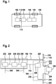
Fig. 2 ein Blockschaltbild einer Vorrichtung zum Abschalten zumindest einer Zündendstufe für eine Zündpille eines pyrotechnischen Schutzmittels für ein Fahrzeug gemäß einem Ausführungsbeispiel der vorliegenden Erfindung; -
Fig. 3 ein Blockschaltbild einer Vorrichtung zum Abschalten zumindest einer Zündendstufe für eine Zündpille gemäß einem Ausführungsbeispiel der vorliegenden Erfindung; -
Fig. 4 einen Schaltplan einer Zündendstufenvorrichtung mit einer Zündendstufe für eine Zündpille und mit einer Vorrichtung zum Abschalten der Zündendstufe gemäß einem Ausführungsbeispiel der vorliegenden Erfindung; und -
Fig. 5 ein Ablaufdiagramm eines Verfahrens zum Abschalten zumindest einer Zündendstufe für eine Zündpille eines pyrotechnischen Schutzmittels für ein Fahrzeug gemäß einem Ausführungsbeispiel der vorliegenden Erfindung.
-
Fig. 1 a vehicle with a device for switching off at least one ignition output stage according to an embodiment of the present invention. -
Fig. 2 a block diagram of an apparatus for switching off at least one ignition output stage for a squib of a pyrotechnic protection means for a vehicle according to an embodiment of the present invention; -
Fig. 3 a block diagram of an apparatus for switching off at least one ignition stage for a squib according to an embodiment of the present invention; -
Fig. 4 a circuit diagram of a Zündendstufenvorrichtung with a detonator for a squib and with a device for switching off the ignition output stage according to an embodiment of the present invention; and -
Fig. 5 a flowchart of a method for switching off at least one ignition output stage for a squib of a pyrotechnic protective means for a vehicle according to an embodiment of the present invention.
In der nachfolgenden Beschreibung günstiger Ausführungsbeispiele der vorliegenden Erfindung werden für die in den verschiedenen Figuren dargestellten und ähnlich wirkenden Elemente gleiche oder ähnliche Bezugszeichen verwendet, wobei auf eine wiederholte Beschreibung dieser Elemente verzichtet wird.In the following description of favorable embodiments of the present invention, the same or similar reference numerals are used for the elements shown in the various figures and similar acting, with a repeated description of these elements is omitted.
Die Vorrichtung 102 ist ausgebildet, den Ansteuerstrom 110 zu überwachen und ein Schaltsignal 112 bereitzustellen, um die Zündendstufe 104 abzuschalten, wenn die Minimalanforderungen an den Ansteuerstrom zum Zünden der Zündpille 106 erfüllt sind.The
Ein Aspekt des vorlegenden Ausführungsbeispiels ist eine Abschaltung von Zündendstufen 104 in Airbagsteuergeräten in Abhängigkeit der Stromflussdauer durch die Zündpille 106. In dem in
Die Zündendstufe 104 umfasst gemäß diesem Ausführungsbeispiel einen ersten Schalter 214, einen zweiten Schalter 216 sowie zwei Anschlüsse 222, 224 zum Anschließen der Zündpille 106. Die zwei Schalter 214, 216 sind in einer Serienschaltung zwischen einem ersten Potenzialanschluss 218, beispielsweise einer Spannungsquelle, und einem zweiten Potenzialanschluss 220, beispielsweise einem Masseanschluss, geschaltet. Wenn die Schalter 214, 216 geschlossen sind, kann der Ansteuerstrom 110 über die Schalter 214, 216 sowie die an den Anschlüssen 222, 224 angeschlossene Zündpille 106 fließen und dadurch ein Zünden der Zündpille 106 bewirken.The
In dem gezeigten Ausführungsbeispiel umfasst die Zündendstufe 104 eine Ansteuereinrichtung 226 zum Ansteuern der beiden Schalter 214, 216 ansprechend auf das Schaltsignal 112. Dabei ist die Ansteuereinrichtung 226 ausgebildet, das Schaltsignal 112 zu empfangen und in entsprechende Steuersignale 228, 230 umzusetzen. Dabei steuert das Steuersignal 228 den ersten Schalter 214 und das Steuersignal 230 den zweiten Schalter 216.In the exemplary embodiment shown, the
In einem nicht gezeigten Ausführungsbeispiel weist die Zündendstufe 104 nur einen Schalter auf, beispielsweise den ersten Schalter 214 oder alternativ den zweiten Schalter 216. In einem Ausführungsbeispiel wird das Schaltsignal 112 direkt an den Schalter 214, den Schalter 216 oder alternativ die beiden Schalter 214, 216 geleitet. In dem Fall umfasst die Zündendstufe 104 keine Ansteuereinrichtung 226.In one embodiment, not shown, the
Auch bei der Vorrichtung 102 kann es sich um ein Ausführungsbeispiel einer in
Das hier vorgestellte Ausführungsbeispiel einer Vorrichtung 102 erlaubt beim Design der Zündendstufen 104 und ihrer Ansteuerung, durch die sichere Erfüllung der Minimalanforderung des Zündpillenherstellers, eine optimale Auslegung der Endstufen 104 und damit eine Kostenersparnis. Dabei ist ein Aspekt des vorgestellten Ausführungsbeispiels, dass die Zeitdauer, in der der geforderte Mindeststrom fließt, gemessen oder bestimmt wird und bei Erreichen der geforderten Mindeststromflussdauer die Leistungsendstufen 104 eigenständig ausgeschalten werden. Durch die Minimierung der Aktivierungszeit der Endstufen ist die Verlustleistung über diesen Baugruppen wesentlich kleiner. Dadurch wiederum kann die Baugruppe auch flächenmäßig kleiner ausgeführt werden, was zu einer Kostenreduzierung führt.The embodiment of a
In dem gezeigten Ausführungsbeispiel weist die Setzeinrichtung 232 einen Stromwandler 350 und einen Komparator 352 auf. Der Stromwandler 350 ist ausgebildet, eine Stromstärke des Ansteuerstroms 110 zu bestimmen. Dabei handelt es sich in einem Ausführungsbeispiel bei dem Stromwandler 350 um einen Strommesser 350 oder ein anderes geeignetes Messgerät zum Erfassen der Stromstärke des Ansteuerstroms 110. Der Komparator 352 ist ausgebildet, die von dem Stromwandler 350 erfasste Stromstärke mit einem einen Stromschwellenwert repräsentierenden Schwellenstrom 354 oder Stromschwellenwertsignal 354 unter Verwendung des Komparators 352 zu vergleichen.In the exemplary embodiment shown, the
Die Bestimmeinrichtung 234 umfasst einen Zähler 356, der ausgebildet ist, die Zeitdauer zu bestimmen, in der das Aktivierungssignal 238 auf den Aktivierungspegel gesetzt ist. Dabei repräsentiert ein Zählerstand 358 des Zählers 356 die Zeitdauer 242.The determining means 234 comprises a
Weiterhin ist die Schnittstelle 236 ausgebildet, die Zeitdauer 242 bzw. den die Zeitdauer 242 repräsentierenden Zählerstand 358 mit einem vorabdefinierten Schwellenwert 360 zu vergleichen. Dabei repräsentiert der Schwellenwert 360 eine Mindeststromflussdauer zum Zünden der Zündpille. Die Schnittstelle 236 ist ausgebildet, das Schaltsignal 112 bereitzustellen, wenn die Zeitdauer 242 zumindest den Wert der Mindeststromflussdauer aufweist.Furthermore, the
In einem nicht gezeigten Ausführungsbeispiel umfasst die Vorrichtung 102 eine Ansteuereinrichtung zum Ansteuern zumindest einer Zündendstufe ansprechend auf das Schaltsignal 112. Eine Variante der Ansteuereinrichtung ist in
In einem Ausführungsbeispiel umfasst die Zündendstufe zumindest einen MOSFET-Transistor, insbesondere einen MOSFET-Transistor zum Einschalten und Ausschalten des Ansteuerstroms 110.In one exemplary embodiment, the ignition output stage comprises at least one MOSFET transistor, in particular a MOSFET transistor for switching on and off the drive current 110.
Bei der Vorrichtung 102 kann es sich um ein Ausführungsbeispiel einer in
Ein Zählerstand 358 des Zählers 356 wird ansprechend auf das Aktivierungssignal 238 und ein Signal 466 des Zeitimpulsgebers 462 inkrementiert. Die Vergleichseinrichtung der Schnittstelle 236 ist ausgebildet, das Schaltsignal 112 bereitzustellen, wenn der Zählerstand 358 den Schwellenwert 360 überschreitet.A
An einem Anschluss der Vorrichtung 102 ist ein Ansteuerstrom 110 einleitbar oder messbar. Der Anschluss der Vorrichtung 102 ist gemäß diesem Ausführungsbeispiel über einen Messwiderstand 468 des Stromwandlers 350 bzw. des Strommessers 350 mit einer Leitung zum Leiten des Ansteuerstroms 110 durch die Zündendstufe 104 gekoppelt. Der Messwiderstand 468 ist dabei an einer geeigneten Position innerhalb der Leitung zum Leiten des Ansteuerstroms 110 angeordnet. In einem nicht gezeigten Ausführungsbeispiel ist der Anschluss der Vorrichtung 102 über eine Messspule des Strommessers 350 mit der Leitung zum Leiten des Ansteuerstroms 110 durch die Zündendstufe 104 gekoppelt. Die Messspule ist dabei an einer geeigneten Position innerhalb der Leitung zum Leiten des Ansteuerstroms 110 angeordnet.At a terminal of the
Der Anschluss 218 wird auch als "High_out" bezeichnet, der Anschluss 220 wird auch als "Low_out" bezeichnet.
Der erste Schalter 214 wird auch als Highside-Schalter oder T1 bezeichnet. Der zweite Schalter 216 wird auch als Lowside-Schalter oder T2 bezeichnet. In einem Ausführungsbeispiel sind die beiden Schalter 214, 216 als Transistoren, insbesondere als MOSFET Transistoren, beispielsweise als N-Kanal MOSFET, ausgeführt. Der erste Schalter 214 ist beispielhaft zwischen dem Anschluss 218, auch als High_out" bezeichnet, und dem Anschluss der Vorrichtung 102 zum Erfassen des Ansteuerstroms 110 angeordnet. Der zweite Schalter 216 ist zwischen dem auch als "Low_out" bezeichneten Anschluss 220 und einem Masseanschluss angeordnet.The
Die Zündendstufe 104 weist in dem in
Ein Ausgang des Stromwandlers 350, an dem das Stromstärkesignal 464 anliegt, ist mit einem Eingang des Komparators 352 verbunden. Ein weiterer Eingang des Komparators 352 ist über einen ersten Komparatorwiderstand mit einem Anschluss für das Stromschwellenwertsignal 354 und über einen zweiten Komparatorwiderstand mit Masse verbunden. Am Ausgang des Komparators 352 liegt das Aktivierungssignal 238 an. Der Ausgang des Komparators 352 ist mit einem Eingang des Zählers 356 verbunden. Ein Impulsgeber 462 stellt ein Signal 466 bereit. Der Zähler 356 ist ausgebildet, unter Verwendung des Signals 466 des Impulsgebers 462 und dem Aktivierungssignal 238 einen Zählerstand 358 zu inkrementieren. Der Zähler 356 ist mit der Schnittstelle 236 verbunden. Die Schnittstelle 236 ist ausgebildet, das Schaltsignal 112 bereitzustellen, wobei das Schaltsignal 112 ausgegeben wird, wenn der Zählerstand 358 den Schwellenwert 360 erreicht oder alternativ übersteigt. Die Schnittstelle 236 ist mit der Ansteuereinrichtung 226 verbunden. Die Ansteuereinrichtung 226 ist ausgebildet, die Zündendstufe 104 ansprechend auf das Schaltsignal 112 anzusteuern. Die Ansteuereinrichtung 226 ist über einen Anschluss der Zündstufe 104 mit dem ersten Schalter 214 sowie zusätzlich oder alternativ mit dem zweiten Schalter 216 verbunden.An output of the
Der Strom 110, der über den ersten Schalter 214 (Transistor 1; T1), die Zündpille 106 und den zweiten Schalter 216 (Transistor 2; T2) nach Masse fließt, wird unter Verwendung der Vorrichtung 102 gemessen und der Wert dieses Ansteuerstroms 110 wird an den Komparator 352 geführt. Die Schwelle des Komparators 352 wird in Abhängigkeit des geforderten Zündstrom-Niveaus festgelegt. Solange der durch das Stromstärkesignal 464 angezeigte gemessene Strom 110 über der geforderten Schwelle 354 liegt, wird ein Zeitgeber 462 freigeschaltet, der in einem festgelegten Zeitintervall einen Zähler 356 inkrementiert. Hat dieser Zähler 356 den Zählerstand 358, der der geforderten Aktivierungszeit entspricht, erreicht, werden die beiden Schalter 214, 216 oder Endstufen (T1 und T2) ausgeschalten.The current 110 flowing to ground through the first switch 214 (transistor 1; T1),
In einem Ausführungsbeispiel umfasst das Verfahren einen optionalen, hier nicht gezeigten, Schritt des Ansteuerns zumindest einer Zündendstufe und ergänzend oder alternativ einer weiteren Zündendstufe ansprechend auf das Schaltsignal.In one exemplary embodiment, the method includes an optional step, not shown here, of activating at least one ignition output stage and additionally or alternatively a further ignition output stage in response to the switching signal.
Die beschriebenen und in den Figuren gezeigten Ausführungsbeispiele sind nur beispielhaft gewählt. Unterschiedliche Ausführungsbeispiele können vollständig oder in Bezug auf einzelne Merkmale miteinander kombiniert werden. Auch kann ein Ausführungsbeispiel durch Merkmale eines weiteren Ausführungsbeispiels ergänzt werden.The embodiments described and shown in the figures are chosen only by way of example. Different embodiments may be combined together or in relation to individual features. Also, an embodiment can be supplemented by features of another embodiment.
Ferner können die hier vorgestellten Verfahrensschritte wiederholt sowie in einer anderen als in der beschriebenen Reihenfolge ausgeführt werden.Furthermore, the method steps presented here can be repeated as well as executed in a sequence other than that described.
Umfasst ein Ausführungsbeispiel eine "und/oder"-Verknüpfung zwischen einem ersten Merkmal und einem zweiten Merkmal, so ist dies so zu lesen, dass das Ausführungsbeispiel gemäß einer Ausführungsform sowohl das erste Merkmal als auch das zweite Merkmal und gemäß einer weiteren Ausführungsform entweder nur das erste Merkmal oder nur das zweite Merkmal aufweist.If an exemplary embodiment comprises a "and / or" link between a first feature and a second feature, then this is to be read so that the embodiment according to one embodiment, both the first feature and the second feature and according to another embodiment either only first feature or only the second feature.
Claims (10)
- Method (580) for shutting down at least one ignition output stage (104) for an igniter (106) for a pyrotechnic protection means (108) for a vehicle (100), wherein the method (580) has the following steps:setting (582) an activation signal (238) to an activation level if a current intensity (464) of an actuation current (110) for the ignition output stage (104) exceeds a previously defined current threshold value (354);determining (584) a period (242) in which the activation signal (238) is set to the activation level; andproviding (586) a switching signal (112) for shutting down the ignition output stage (104), on the basis of a comparison of the period (242) with a previously defined minimum current flow time (244).
- Method (580) according to Claim 1, in which the determination step (584) entails the period (242) being determined by using a counter (356), wherein a count (358) of the counter (356) represents the period (242).
- Method (580) according to either of the preceding claims, in which the provision step (586) entails the period (242) and/or the count (358) being compared with a previously defined threshold value (360), wherein the threshold value (360) represents the minimum current flow time (244).
- Method (580) according to one of the preceding claims, in which the setting step (582) entails the current intensity (464) being determined by using a current transformer (350).
- Method (580) according to one of the preceding claims, in which the setting step (582) entails the current intensity (464) being compared with a threshold current (354) representing the current threshold value (354) by using a comparator (352).
- Method (580) according to one of the preceding claims, having a step of actuating an ignition output stage (104) in response to the switching signal (112).
- Apparatus (102) for shutting down at least one ignition output stage (104) for an igniter (106) of a pyrotechnic protection means (108) for a vehicle (100), wherein the apparatus (102) has the following features:a setting device (232) for setting an activation signal (238) to an activation level if a current intensity (464) of an actuation current (110) for the ignition output stage (104) exceeds a previously defined current threshold value (354), wherein the setting device (232) comprises a current transformer (350) and a comparator (352) ;a determining device (234) for determining a period (242) in which the activation signal (238) is set to the activation level, wherein the determining device (234) comprises a counter (356) and a time pulse transmitter (462); andan interface (236) for providing a switching signal (112) for shutting down the ignition output stage (104), on the basis of a comparison of the period (242) with a previously defined minimum current flow time (244), wherein the interface (236) comprises a comparison device, wherein the current transformer (350) is configured to capture the actuation current (110) and to provide a current intensity signal (464) representing the actuation current (110), wherein the comparator (352) is configured to set the activation signal (238) to the activation level if the current intensity signal (464) exceeds a current threshold value signal (354), wherein a count (358) of the counter (356) is incremented in response to the activation signal (238) and a signal (466) from the time pulse transmitter (462) and wherein the comparison device is configured to provide the switching signal (112) if the count (358) exceeds the threshold value (360).
- Ignition output stage apparatus having the following features:an ignition output stage (104) having a high-side switch (214) and a low-side switch (216) for controlling an actuation current (110) and having an interface for providing the actuation current (110) to an igniter (106) for a pyrotechnic protection means (108) for a vehicle (100); andan apparatus (102) according to Claim 7, wherein the interface (236) of the apparatus (102) is configured to provide the switching signal (112) as a control signal for at least one of the switches (214, 216).
- Computer program set up to perform all the steps of a method (580) according to one of Claims 1 to 6.
- Machine-readable storage medium having a computer program according to Claim 9 stored thereon.
Applications Claiming Priority (2)
| Application Number | Priority Date | Filing Date | Title |
|---|---|---|---|
| DE102014207302.2A DE102014207302A1 (en) | 2014-04-16 | 2014-04-16 | Method and device for switching off at least one ignition output stage for a squib of a pyrotechnic protective agent for a vehicle |
| PCT/EP2015/056568 WO2015158519A1 (en) | 2014-04-16 | 2015-03-26 | Method and apparatus for disconnecting at least one ignition output stage for a firing cap of a pyrotechnic protection means for a vehicle |
Publications (2)
| Publication Number | Publication Date |
|---|---|
| EP3131793A1 EP3131793A1 (en) | 2017-02-22 |
| EP3131793B1 true EP3131793B1 (en) | 2018-08-22 |
Family
ID=52781068
Family Applications (1)
| Application Number | Title | Priority Date | Filing Date |
|---|---|---|---|
| EP15713440.4A Active EP3131793B1 (en) | 2014-04-16 | 2015-03-26 | Method and apparatus for disconnecting at least one ignition output stage for a firing cap of a pyrotechnic protection means for a vehicle |
Country Status (7)
| Country | Link |
|---|---|
| US (1) | US10179560B2 (en) |
| EP (1) | EP3131793B1 (en) |
| JP (1) | JP6875858B2 (en) |
| KR (1) | KR102307034B1 (en) |
| CN (1) | CN106170419B (en) |
| DE (1) | DE102014207302A1 (en) |
| WO (1) | WO2015158519A1 (en) |
Families Citing this family (3)
| Publication number | Priority date | Publication date | Assignee | Title |
|---|---|---|---|---|
| DE102014207302A1 (en) | 2014-04-16 | 2015-10-22 | Robert Bosch Gmbh | Method and device for switching off at least one ignition output stage for a squib of a pyrotechnic protective agent for a vehicle |
| US10833499B2 (en) | 2017-10-25 | 2020-11-10 | Texas Instruments Incorporated | Pyro-fuse circuit |
| DE102019211727A1 (en) * | 2019-08-05 | 2021-02-11 | Audi Ag | Method for operating an electrically drivable motor vehicle and a device for this purpose |
Family Cites Families (14)
| Publication number | Priority date | Publication date | Assignee | Title |
|---|---|---|---|---|
| CA2106603C (en) * | 1992-09-21 | 1997-09-16 | Masahiro Miyamori | Crash/non-crash discrimination using frequency components of acceleration uniquely generated upon crash impact |
| JPH07228215A (en) * | 1994-02-17 | 1995-08-29 | Mitsubishi Electric Corp | Control circuit for vehicular safety device |
| FR2732286B1 (en) * | 1995-03-31 | 1997-06-13 | Davey Bickford | VEHICLE SECURITY DEVICE |
| FR2744862B1 (en) * | 1996-02-12 | 1998-04-30 | Motorola Semiconducteurs | CIRCUIT FOR CONTROLLING THE ELECTRICAL SUPPLY OF AN IGNITOR ELEMENT |
| US5666065A (en) * | 1996-05-22 | 1997-09-09 | Delco Electronics Corp. | Fast acting FET test circuit for SIR diagnostics |
| US5872460A (en) * | 1996-10-04 | 1999-02-16 | Delco Electronics Corp. | Fast acting FET test circuit with current detection for SIR diagnostics |
| NL1019796C2 (en) * | 2002-01-21 | 2003-07-23 | Eduard Ronald Mari Plantinga | A security system for automatically switching off airbags and the like in a vehicle or vessel. |
| JP2009067289A (en) * | 2007-09-14 | 2009-04-02 | Fujitsu Ten Ltd | Ignition control circuit of inflater, semiconductor integrated circuit, and occupant crash protection control device |
| ES1067069Y (en) * | 2008-01-18 | 2008-07-16 | Vilalta Antonio Soriano | TIMED OPENING DEVICE FOR VEHICLE SAFETY BELT HITCHES |
| US8229630B2 (en) * | 2008-02-11 | 2012-07-24 | Infineon Technologies Ag | Electronic airbag control unit having an autonomous event data recorder |
| JP2009196541A (en) * | 2008-02-22 | 2009-09-03 | Fujitsu Ten Ltd | Airbag ignition circuit and airbag ignition unit |
| DE102012210874A1 (en) * | 2012-06-26 | 2014-01-23 | Robert Bosch Gmbh | Method for detecting, for diagnosing and triggering a triggering device for a passenger protection device for a vehicle and device for detecting and triggering a triggering device for a personal protection device |
| US20140188347A1 (en) * | 2012-12-31 | 2014-07-03 | Joseph Akwo Tabe | Smart supplemental restraint and occupant classification system |
| DE102014207302A1 (en) | 2014-04-16 | 2015-10-22 | Robert Bosch Gmbh | Method and device for switching off at least one ignition output stage for a squib of a pyrotechnic protective agent for a vehicle |
-
2014
- 2014-04-16 DE DE102014207302.2A patent/DE102014207302A1/en not_active Withdrawn
-
2015
- 2015-03-26 CN CN201580019669.8A patent/CN106170419B/en active Active
- 2015-03-26 US US15/301,993 patent/US10179560B2/en active Active
- 2015-03-26 EP EP15713440.4A patent/EP3131793B1/en active Active
- 2015-03-26 JP JP2016562826A patent/JP6875858B2/en active Active
- 2015-03-26 KR KR1020167031613A patent/KR102307034B1/en active IP Right Grant
- 2015-03-26 WO PCT/EP2015/056568 patent/WO2015158519A1/en active Application Filing
Also Published As
| Publication number | Publication date |
|---|---|
| US10179560B2 (en) | 2019-01-15 |
| KR20160146813A (en) | 2016-12-21 |
| KR102307034B1 (en) | 2021-10-01 |
| JP2017513757A (en) | 2017-06-01 |
| EP3131793A1 (en) | 2017-02-22 |
| WO2015158519A1 (en) | 2015-10-22 |
| DE102014207302A1 (en) | 2015-10-22 |
| JP6875858B2 (en) | 2021-05-26 |
| CN106170419B (en) | 2019-04-12 |
| CN106170419A (en) | 2016-11-30 |
| US20170106825A1 (en) | 2017-04-20 |
Similar Documents
| Publication | Publication Date | Title |
|---|---|---|
| DE102012216529B4 (en) | Method for triggering at least one personal protection device as well as system and computer program product for carrying out the method | |
| EP0400002B1 (en) | Process for operating a safety device for vehicle passengers | |
| EP2997388B1 (en) | Method and apparatus for identifying a polarity of a freewheeling diode, actuator circuit and safety apparatus for a vehicle | |
| DE102010043882B4 (en) | Clocked safety switch | |
| DE102012221794B4 (en) | A method of testing a power supply controller and integrated circuit with a power supply controller | |
| DE3925594A1 (en) | ELECTRONIC DEVICE AND OPERATING METHOD | |
| EP3131793B1 (en) | Method and apparatus for disconnecting at least one ignition output stage for a firing cap of a pyrotechnic protection means for a vehicle | |
| DE102011089147B4 (en) | Method and device for operating a triggering device for occupant protection means | |
| DE102012210874A1 (en) | Method for detecting, for diagnosing and triggering a triggering device for a passenger protection device for a vehicle and device for detecting and triggering a triggering device for a personal protection device | |
| EP1062131B1 (en) | Method for operating an occupant safety device, and a control unit | |
| DE19837167A1 (en) | Function and switch checking process for ignition circuit of vehicle occupant protection device | |
| DE102013211421B4 (en) | Device for operating a cold gas generator, safety device for a vehicle and method for controlling a device for operating a cold gas generator | |
| DE19752622C1 (en) | Motor vehicle occupant protection system with a plurality of squibs, and method for actuating an ignition circuit of such an occupant protection system | |
| DE8816606U1 (en) | Electronic device | |
| DE19702899C1 (en) | Pyrotechnical ignition device control method for motor vehicle airbag gas generator | |
| DE19532628A1 (en) | Method for checking an ignition element and suitable electronic device | |
| EP2394865B1 (en) | Method and device for diagnosing the functioning of an energy supply device | |
| DE102004020681B4 (en) | Device for controlling personal protective equipment | |
| DE102014219048A1 (en) | Apparatus and method for determining a short circuit across a load | |
| DE10109637B4 (en) | Method for operating an occupant safety device | |
| DE10125812B4 (en) | Actuating device for safety devices, in particular on motor vehicles | |
| EP2807056B1 (en) | Method and arrangement for actuating at least one triggering element for a personal protection means | |
| DE102006047379B4 (en) | Device and method for energizing a Zündkreisschaltung for personal protection | |
| DE19850868C1 (en) | Detonator capsule detonation circuit | |
| EP2703231B1 (en) | Sensor system for a person protection system of a vehicle and person protection system for a vehicle |
Legal Events
| Date | Code | Title | Description |
|---|---|---|---|
| STAA | Information on the status of an ep patent application or granted ep patent |
Free format text: STATUS: THE INTERNATIONAL PUBLICATION HAS BEEN MADE |
|
| PUAI | Public reference made under article 153(3) epc to a published international application that has entered the european phase |
Free format text: ORIGINAL CODE: 0009012 |
|
| STAA | Information on the status of an ep patent application or granted ep patent |
Free format text: STATUS: REQUEST FOR EXAMINATION WAS MADE |
|
| 17P | Request for examination filed |
Effective date: 20161116 |
|
| AK | Designated contracting states |
Kind code of ref document: A1 Designated state(s): AL AT BE BG CH CY CZ DE DK EE ES FI FR GB GR HR HU IE IS IT LI LT LU LV MC MK MT NL NO PL PT RO RS SE SI SK SM TR |
|
| AX | Request for extension of the european patent |
Extension state: BA ME |
|
| DAV | Request for validation of the european patent (deleted) | ||
| DAX | Request for extension of the european patent (deleted) | ||
| GRAP | Despatch of communication of intention to grant a patent |
Free format text: ORIGINAL CODE: EPIDOSNIGR1 |
|
| STAA | Information on the status of an ep patent application or granted ep patent |
Free format text: STATUS: GRANT OF PATENT IS INTENDED |
|
| INTG | Intention to grant announced |
Effective date: 20180507 |
|
| GRAS | Grant fee paid |
Free format text: ORIGINAL CODE: EPIDOSNIGR3 |
|
| GRAA | (expected) grant |
Free format text: ORIGINAL CODE: 0009210 |
|
| STAA | Information on the status of an ep patent application or granted ep patent |
Free format text: STATUS: THE PATENT HAS BEEN GRANTED |
|
| AK | Designated contracting states |
Kind code of ref document: B1 Designated state(s): AL AT BE BG CH CY CZ DE DK EE ES FI FR GB GR HR HU IE IS IT LI LT LU LV MC MK MT NL NO PL PT RO RS SE SI SK SM TR |
|
| REG | Reference to a national code |
Ref country code: GB Ref legal event code: FG4D Free format text: NOT ENGLISH |
|
| REG | Reference to a national code |
Ref country code: CH Ref legal event code: EP |
|
| REG | Reference to a national code |
Ref country code: AT Ref legal event code: REF Ref document number: 1032076 Country of ref document: AT Kind code of ref document: T Effective date: 20180915 |
|
| REG | Reference to a national code |
Ref country code: IE Ref legal event code: FG4D Free format text: LANGUAGE OF EP DOCUMENT: GERMAN |
|
| REG | Reference to a national code |
Ref country code: DE Ref legal event code: R096 Ref document number: 502015005551 Country of ref document: DE |
|
| REG | Reference to a national code |
Ref country code: SE Ref legal event code: TRGR |
|
| REG | Reference to a national code |
Ref country code: NL Ref legal event code: MP Effective date: 20180822 |
|
| REG | Reference to a national code |
Ref country code: LT Ref legal event code: MG4D |
|
| PG25 | Lapsed in a contracting state [announced via postgrant information from national office to epo] |
Ref country code: NO Free format text: LAPSE BECAUSE OF FAILURE TO SUBMIT A TRANSLATION OF THE DESCRIPTION OR TO PAY THE FEE WITHIN THE PRESCRIBED TIME-LIMIT Effective date: 20181122 Ref country code: BG Free format text: LAPSE BECAUSE OF FAILURE TO SUBMIT A TRANSLATION OF THE DESCRIPTION OR TO PAY THE FEE WITHIN THE PRESCRIBED TIME-LIMIT Effective date: 20181122 Ref country code: IS Free format text: LAPSE BECAUSE OF FAILURE TO SUBMIT A TRANSLATION OF THE DESCRIPTION OR TO PAY THE FEE WITHIN THE PRESCRIBED TIME-LIMIT Effective date: 20181222 Ref country code: RS Free format text: LAPSE BECAUSE OF FAILURE TO SUBMIT A TRANSLATION OF THE DESCRIPTION OR TO PAY THE FEE WITHIN THE PRESCRIBED TIME-LIMIT Effective date: 20180822 Ref country code: GR Free format text: LAPSE BECAUSE OF FAILURE TO SUBMIT A TRANSLATION OF THE DESCRIPTION OR TO PAY THE FEE WITHIN THE PRESCRIBED TIME-LIMIT Effective date: 20181123 Ref country code: FI Free format text: LAPSE BECAUSE OF FAILURE TO SUBMIT A TRANSLATION OF THE DESCRIPTION OR TO PAY THE FEE WITHIN THE PRESCRIBED TIME-LIMIT Effective date: 20180822 Ref country code: NL Free format text: LAPSE BECAUSE OF FAILURE TO SUBMIT A TRANSLATION OF THE DESCRIPTION OR TO PAY THE FEE WITHIN THE PRESCRIBED TIME-LIMIT Effective date: 20180822 Ref country code: LT Free format text: LAPSE BECAUSE OF FAILURE TO SUBMIT A TRANSLATION OF THE DESCRIPTION OR TO PAY THE FEE WITHIN THE PRESCRIBED TIME-LIMIT Effective date: 20180822 |
|
| PG25 | Lapsed in a contracting state [announced via postgrant information from national office to epo] |
Ref country code: AL Free format text: LAPSE BECAUSE OF FAILURE TO SUBMIT A TRANSLATION OF THE DESCRIPTION OR TO PAY THE FEE WITHIN THE PRESCRIBED TIME-LIMIT Effective date: 20180822 Ref country code: HR Free format text: LAPSE BECAUSE OF FAILURE TO SUBMIT A TRANSLATION OF THE DESCRIPTION OR TO PAY THE FEE WITHIN THE PRESCRIBED TIME-LIMIT Effective date: 20180822 Ref country code: LV Free format text: LAPSE BECAUSE OF FAILURE TO SUBMIT A TRANSLATION OF THE DESCRIPTION OR TO PAY THE FEE WITHIN THE PRESCRIBED TIME-LIMIT Effective date: 20180822 |
|
| PG25 | Lapsed in a contracting state [announced via postgrant information from national office to epo] |
Ref country code: EE Free format text: LAPSE BECAUSE OF FAILURE TO SUBMIT A TRANSLATION OF THE DESCRIPTION OR TO PAY THE FEE WITHIN THE PRESCRIBED TIME-LIMIT Effective date: 20180822 Ref country code: RO Free format text: LAPSE BECAUSE OF FAILURE TO SUBMIT A TRANSLATION OF THE DESCRIPTION OR TO PAY THE FEE WITHIN THE PRESCRIBED TIME-LIMIT Effective date: 20180822 Ref country code: CZ Free format text: LAPSE BECAUSE OF FAILURE TO SUBMIT A TRANSLATION OF THE DESCRIPTION OR TO PAY THE FEE WITHIN THE PRESCRIBED TIME-LIMIT Effective date: 20180822 Ref country code: PL Free format text: LAPSE BECAUSE OF FAILURE TO SUBMIT A TRANSLATION OF THE DESCRIPTION OR TO PAY THE FEE WITHIN THE PRESCRIBED TIME-LIMIT Effective date: 20180822 Ref country code: ES Free format text: LAPSE BECAUSE OF FAILURE TO SUBMIT A TRANSLATION OF THE DESCRIPTION OR TO PAY THE FEE WITHIN THE PRESCRIBED TIME-LIMIT Effective date: 20180822 |
|
| REG | Reference to a national code |
Ref country code: DE Ref legal event code: R097 Ref document number: 502015005551 Country of ref document: DE |
|
| PG25 | Lapsed in a contracting state [announced via postgrant information from national office to epo] |
Ref country code: SK Free format text: LAPSE BECAUSE OF FAILURE TO SUBMIT A TRANSLATION OF THE DESCRIPTION OR TO PAY THE FEE WITHIN THE PRESCRIBED TIME-LIMIT Effective date: 20180822 Ref country code: SM Free format text: LAPSE BECAUSE OF FAILURE TO SUBMIT A TRANSLATION OF THE DESCRIPTION OR TO PAY THE FEE WITHIN THE PRESCRIBED TIME-LIMIT Effective date: 20180822 Ref country code: DK Free format text: LAPSE BECAUSE OF FAILURE TO SUBMIT A TRANSLATION OF THE DESCRIPTION OR TO PAY THE FEE WITHIN THE PRESCRIBED TIME-LIMIT Effective date: 20180822 |
|
| PLBE | No opposition filed within time limit |
Free format text: ORIGINAL CODE: 0009261 |
|
| STAA | Information on the status of an ep patent application or granted ep patent |
Free format text: STATUS: NO OPPOSITION FILED WITHIN TIME LIMIT |
|
| 26N | No opposition filed |
Effective date: 20190523 |
|
| PG25 | Lapsed in a contracting state [announced via postgrant information from national office to epo] |
Ref country code: SI Free format text: LAPSE BECAUSE OF FAILURE TO SUBMIT A TRANSLATION OF THE DESCRIPTION OR TO PAY THE FEE WITHIN THE PRESCRIBED TIME-LIMIT Effective date: 20180822 |
|
| PG25 | Lapsed in a contracting state [announced via postgrant information from national office to epo] |
Ref country code: MC Free format text: LAPSE BECAUSE OF FAILURE TO SUBMIT A TRANSLATION OF THE DESCRIPTION OR TO PAY THE FEE WITHIN THE PRESCRIBED TIME-LIMIT Effective date: 20180822 |
|
| REG | Reference to a national code |
Ref country code: CH Ref legal event code: PL |
|
| GBPC | Gb: european patent ceased through non-payment of renewal fee |
Effective date: 20190326 |
|
| PG25 | Lapsed in a contracting state [announced via postgrant information from national office to epo] |
Ref country code: LU Free format text: LAPSE BECAUSE OF NON-PAYMENT OF DUE FEES Effective date: 20190326 |
|
| REG | Reference to a national code |
Ref country code: BE Ref legal event code: MM Effective date: 20190331 |
|
| PG25 | Lapsed in a contracting state [announced via postgrant information from national office to epo] |
Ref country code: GB Free format text: LAPSE BECAUSE OF NON-PAYMENT OF DUE FEES Effective date: 20190326 Ref country code: LI Free format text: LAPSE BECAUSE OF NON-PAYMENT OF DUE FEES Effective date: 20190331 Ref country code: IE Free format text: LAPSE BECAUSE OF NON-PAYMENT OF DUE FEES Effective date: 20190326 Ref country code: CH Free format text: LAPSE BECAUSE OF NON-PAYMENT OF DUE FEES Effective date: 20190331 |
|
| PG25 | Lapsed in a contracting state [announced via postgrant information from national office to epo] |
Ref country code: BE Free format text: LAPSE BECAUSE OF NON-PAYMENT OF DUE FEES Effective date: 20190331 |
|
| PG25 | Lapsed in a contracting state [announced via postgrant information from national office to epo] |
Ref country code: TR Free format text: LAPSE BECAUSE OF FAILURE TO SUBMIT A TRANSLATION OF THE DESCRIPTION OR TO PAY THE FEE WITHIN THE PRESCRIBED TIME-LIMIT Effective date: 20180822 |
|
| PG25 | Lapsed in a contracting state [announced via postgrant information from national office to epo] |
Ref country code: PT Free format text: LAPSE BECAUSE OF FAILURE TO SUBMIT A TRANSLATION OF THE DESCRIPTION OR TO PAY THE FEE WITHIN THE PRESCRIBED TIME-LIMIT Effective date: 20181222 Ref country code: MT Free format text: LAPSE BECAUSE OF FAILURE TO SUBMIT A TRANSLATION OF THE DESCRIPTION OR TO PAY THE FEE WITHIN THE PRESCRIBED TIME-LIMIT Effective date: 20180822 |
|
| REG | Reference to a national code |
Ref country code: AT Ref legal event code: MM01 Ref document number: 1032076 Country of ref document: AT Kind code of ref document: T Effective date: 20200326 |
|
| PG25 | Lapsed in a contracting state [announced via postgrant information from national office to epo] |
Ref country code: CY Free format text: LAPSE BECAUSE OF FAILURE TO SUBMIT A TRANSLATION OF THE DESCRIPTION OR TO PAY THE FEE WITHIN THE PRESCRIBED TIME-LIMIT Effective date: 20180822 |
|
| PG25 | Lapsed in a contracting state [announced via postgrant information from national office to epo] |
Ref country code: HU Free format text: LAPSE BECAUSE OF FAILURE TO SUBMIT A TRANSLATION OF THE DESCRIPTION OR TO PAY THE FEE WITHIN THE PRESCRIBED TIME-LIMIT; INVALID AB INITIO Effective date: 20150326 |
|
| PG25 | Lapsed in a contracting state [announced via postgrant information from national office to epo] |
Ref country code: AT Free format text: LAPSE BECAUSE OF NON-PAYMENT OF DUE FEES Effective date: 20200326 |
|
| PG25 | Lapsed in a contracting state [announced via postgrant information from national office to epo] |
Ref country code: MK Free format text: LAPSE BECAUSE OF FAILURE TO SUBMIT A TRANSLATION OF THE DESCRIPTION OR TO PAY THE FEE WITHIN THE PRESCRIBED TIME-LIMIT Effective date: 20180822 |
|
| PGFP | Annual fee paid to national office [announced via postgrant information from national office to epo] |
Ref country code: DE Payment date: 20230524 Year of fee payment: 9 |
|
| PGFP | Annual fee paid to national office [announced via postgrant information from national office to epo] |
Ref country code: SE Payment date: 20240321 Year of fee payment: 10 Ref country code: IT Payment date: 20240329 Year of fee payment: 10 Ref country code: FR Payment date: 20240319 Year of fee payment: 10 |