EP3131746B1 - Polygonal part having cavities for a panel core, in particular of a satellite antenna reflector - Google Patents
Polygonal part having cavities for a panel core, in particular of a satellite antenna reflector Download PDFInfo
- Publication number
- EP3131746B1 EP3131746B1 EP15719260.0A EP15719260A EP3131746B1 EP 3131746 B1 EP3131746 B1 EP 3131746B1 EP 15719260 A EP15719260 A EP 15719260A EP 3131746 B1 EP3131746 B1 EP 3131746B1
- Authority
- EP
- European Patent Office
- Prior art keywords
- core
- recesses
- lugs
- parts
- trapezium
- Prior art date
- Legal status (The legal status is an assumption and is not a legal conclusion. Google has not performed a legal analysis and makes no representation as to the accuracy of the status listed.)
- Not-in-force
Links
- 241000826860 Trapezium Species 0.000 claims description 20
- 230000000295 complement effect Effects 0.000 claims description 11
- 238000004519 manufacturing process Methods 0.000 claims description 9
- 238000000034 method Methods 0.000 claims description 7
- VAOCPAMSLUNLGC-UHFFFAOYSA-N metronidazole Chemical group CC1=NC=C([N+]([O-])=O)N1CCO VAOCPAMSLUNLGC-UHFFFAOYSA-N 0.000 description 6
- 241001080024 Telles Species 0.000 description 5
- 208000003464 asthenopia Diseases 0.000 description 3
- 239000002131 composite material Substances 0.000 description 3
- 229920000049 Carbon (fiber) Polymers 0.000 description 2
- 239000004917 carbon fiber Substances 0.000 description 2
- 238000012423 maintenance Methods 0.000 description 2
- 239000000463 material Substances 0.000 description 2
- 230000002093 peripheral effect Effects 0.000 description 2
- 241000256815 Apocrita Species 0.000 description 1
- 241000219504 Caryophyllales Species 0.000 description 1
- 239000004593 Epoxy Substances 0.000 description 1
- 238000003780 insertion Methods 0.000 description 1
- 230000037431 insertion Effects 0.000 description 1
- 239000011159 matrix material Substances 0.000 description 1
- 238000006116 polymerization reaction Methods 0.000 description 1
- 230000002787 reinforcement Effects 0.000 description 1
- 230000003014 reinforcing effect Effects 0.000 description 1
- 239000011347 resin Substances 0.000 description 1
- 229920005989 resin Polymers 0.000 description 1
- 238000011282 treatment Methods 0.000 description 1
Images


Classifications
-
- B—PERFORMING OPERATIONS; TRANSPORTING
- B32—LAYERED PRODUCTS
- B32B—LAYERED PRODUCTS, i.e. PRODUCTS BUILT-UP OF STRATA OF FLAT OR NON-FLAT, e.g. CELLULAR OR HONEYCOMB, FORM
- B32B3/00—Layered products comprising a layer with external or internal discontinuities or unevennesses, or a layer of non-planar form; Layered products having particular features of form
- B32B3/10—Layered products comprising a layer with external or internal discontinuities or unevennesses, or a layer of non-planar form; Layered products having particular features of form characterised by a discontinuous layer, i.e. formed of separate pieces of material
- B32B3/12—Layered products comprising a layer with external or internal discontinuities or unevennesses, or a layer of non-planar form; Layered products having particular features of form characterised by a discontinuous layer, i.e. formed of separate pieces of material characterised by a layer of regularly- arranged cells, e.g. a honeycomb structure
-
- B—PERFORMING OPERATIONS; TRANSPORTING
- B29—WORKING OF PLASTICS; WORKING OF SUBSTANCES IN A PLASTIC STATE IN GENERAL
- B29C—SHAPING OR JOINING OF PLASTICS; SHAPING OF MATERIAL IN A PLASTIC STATE, NOT OTHERWISE PROVIDED FOR; AFTER-TREATMENT OF THE SHAPED PRODUCTS, e.g. REPAIRING
- B29C65/00—Joining or sealing of preformed parts, e.g. welding of plastics materials; Apparatus therefor
- B29C65/56—Joining or sealing of preformed parts, e.g. welding of plastics materials; Apparatus therefor using mechanical means or mechanical connections, e.g. form-fits
- B29C65/565—Joining or sealing of preformed parts, e.g. welding of plastics materials; Apparatus therefor using mechanical means or mechanical connections, e.g. form-fits involving interference fits, e.g. force-fits or press-fits
-
- B—PERFORMING OPERATIONS; TRANSPORTING
- B29—WORKING OF PLASTICS; WORKING OF SUBSTANCES IN A PLASTIC STATE IN GENERAL
- B29C—SHAPING OR JOINING OF PLASTICS; SHAPING OF MATERIAL IN A PLASTIC STATE, NOT OTHERWISE PROVIDED FOR; AFTER-TREATMENT OF THE SHAPED PRODUCTS, e.g. REPAIRING
- B29C66/00—General aspects of processes or apparatus for joining preformed parts
- B29C66/01—General aspects dealing with the joint area or with the area to be joined
- B29C66/05—Particular design of joint configurations
- B29C66/20—Particular design of joint configurations particular design of the joint lines, e.g. of the weld lines
- B29C66/22—Particular design of joint configurations particular design of the joint lines, e.g. of the weld lines said joint lines being in the form of recurring patterns
- B29C66/227—Particular design of joint configurations particular design of the joint lines, e.g. of the weld lines said joint lines being in the form of recurring patterns being in the form of repetitive interlocking undercuts, e.g. in the form of puzzle cuts
- B29C66/2274—Dovetailed interlocking undercuts
-
- B—PERFORMING OPERATIONS; TRANSPORTING
- B29—WORKING OF PLASTICS; WORKING OF SUBSTANCES IN A PLASTIC STATE IN GENERAL
- B29C—SHAPING OR JOINING OF PLASTICS; SHAPING OF MATERIAL IN A PLASTIC STATE, NOT OTHERWISE PROVIDED FOR; AFTER-TREATMENT OF THE SHAPED PRODUCTS, e.g. REPAIRING
- B29C66/00—General aspects of processes or apparatus for joining preformed parts
- B29C66/70—General aspects of processes or apparatus for joining preformed parts characterised by the composition, physical properties or the structure of the material of the parts to be joined; Joining with non-plastics material
- B29C66/72—General aspects of processes or apparatus for joining preformed parts characterised by the composition, physical properties or the structure of the material of the parts to be joined; Joining with non-plastics material characterised by the structure of the material of the parts to be joined
- B29C66/725—General aspects of processes or apparatus for joining preformed parts characterised by the composition, physical properties or the structure of the material of the parts to be joined; Joining with non-plastics material characterised by the structure of the material of the parts to be joined being hollow-walled or honeycombs
- B29C66/7254—General aspects of processes or apparatus for joining preformed parts characterised by the composition, physical properties or the structure of the material of the parts to be joined; Joining with non-plastics material characterised by the structure of the material of the parts to be joined being hollow-walled or honeycombs honeycomb structures
-
- B—PERFORMING OPERATIONS; TRANSPORTING
- B29—WORKING OF PLASTICS; WORKING OF SUBSTANCES IN A PLASTIC STATE IN GENERAL
- B29D—PRODUCING PARTICULAR ARTICLES FROM PLASTICS OR FROM SUBSTANCES IN A PLASTIC STATE
- B29D99/00—Subject matter not provided for in other groups of this subclass
- B29D99/0089—Producing honeycomb structures
-
- B—PERFORMING OPERATIONS; TRANSPORTING
- B32—LAYERED PRODUCTS
- B32B—LAYERED PRODUCTS, i.e. PRODUCTS BUILT-UP OF STRATA OF FLAT OR NON-FLAT, e.g. CELLULAR OR HONEYCOMB, FORM
- B32B27/00—Layered products comprising a layer of synthetic resin
- B32B27/38—Layered products comprising a layer of synthetic resin comprising epoxy resins
-
- B—PERFORMING OPERATIONS; TRANSPORTING
- B32—LAYERED PRODUCTS
- B32B—LAYERED PRODUCTS, i.e. PRODUCTS BUILT-UP OF STRATA OF FLAT OR NON-FLAT, e.g. CELLULAR OR HONEYCOMB, FORM
- B32B3/00—Layered products comprising a layer with external or internal discontinuities or unevennesses, or a layer of non-planar form; Layered products having particular features of form
- B32B3/02—Layered products comprising a layer with external or internal discontinuities or unevennesses, or a layer of non-planar form; Layered products having particular features of form characterised by features of form at particular places, e.g. in edge regions
- B32B3/06—Layered products comprising a layer with external or internal discontinuities or unevennesses, or a layer of non-planar form; Layered products having particular features of form characterised by features of form at particular places, e.g. in edge regions for securing layers together; for attaching the product to another member, e.g. to a support, or to another product, e.g. groove/tongue, interlocking
-
- B—PERFORMING OPERATIONS; TRANSPORTING
- B32—LAYERED PRODUCTS
- B32B—LAYERED PRODUCTS, i.e. PRODUCTS BUILT-UP OF STRATA OF FLAT OR NON-FLAT, e.g. CELLULAR OR HONEYCOMB, FORM
- B32B5/00—Layered products characterised by the non- homogeneity or physical structure, i.e. comprising a fibrous, filamentary, particulate or foam layer; Layered products characterised by having a layer differing constitutionally or physically in different parts
- B32B5/02—Layered products characterised by the non- homogeneity or physical structure, i.e. comprising a fibrous, filamentary, particulate or foam layer; Layered products characterised by having a layer differing constitutionally or physically in different parts characterised by structural features of a fibrous or filamentary layer
-
- H—ELECTRICITY
- H01—ELECTRIC ELEMENTS
- H01Q—ANTENNAS, i.e. RADIO AERIALS
- H01Q1/00—Details of, or arrangements associated with, antennas
- H01Q1/27—Adaptation for use in or on movable bodies
- H01Q1/28—Adaptation for use in or on aircraft, missiles, satellites, or balloons
- H01Q1/288—Satellite antennas
-
- H—ELECTRICITY
- H01—ELECTRIC ELEMENTS
- H01Q—ANTENNAS, i.e. RADIO AERIALS
- H01Q15/00—Devices for reflection, refraction, diffraction or polarisation of waves radiated from an antenna, e.g. quasi-optical devices
- H01Q15/14—Reflecting surfaces; Equivalent structures
- H01Q15/141—Apparatus or processes specially adapted for manufacturing reflecting surfaces
-
- B—PERFORMING OPERATIONS; TRANSPORTING
- B29—WORKING OF PLASTICS; WORKING OF SUBSTANCES IN A PLASTIC STATE IN GENERAL
- B29C—SHAPING OR JOINING OF PLASTICS; SHAPING OF MATERIAL IN A PLASTIC STATE, NOT OTHERWISE PROVIDED FOR; AFTER-TREATMENT OF THE SHAPED PRODUCTS, e.g. REPAIRING
- B29C65/00—Joining or sealing of preformed parts, e.g. welding of plastics materials; Apparatus therefor
- B29C65/56—Joining or sealing of preformed parts, e.g. welding of plastics materials; Apparatus therefor using mechanical means or mechanical connections, e.g. form-fits
-
- B—PERFORMING OPERATIONS; TRANSPORTING
- B29—WORKING OF PLASTICS; WORKING OF SUBSTANCES IN A PLASTIC STATE IN GENERAL
- B29C—SHAPING OR JOINING OF PLASTICS; SHAPING OF MATERIAL IN A PLASTIC STATE, NOT OTHERWISE PROVIDED FOR; AFTER-TREATMENT OF THE SHAPED PRODUCTS, e.g. REPAIRING
- B29C66/00—General aspects of processes or apparatus for joining preformed parts
- B29C66/01—General aspects dealing with the joint area or with the area to be joined
- B29C66/05—Particular design of joint configurations
- B29C66/10—Particular design of joint configurations particular design of the joint cross-sections
- B29C66/11—Joint cross-sections comprising a single joint-segment, i.e. one of the parts to be joined comprising a single joint-segment in the joint cross-section
- B29C66/112—Single lapped joints
- B29C66/1122—Single lap to lap joints, i.e. overlap joints
-
- B—PERFORMING OPERATIONS; TRANSPORTING
- B29—WORKING OF PLASTICS; WORKING OF SUBSTANCES IN A PLASTIC STATE IN GENERAL
- B29C—SHAPING OR JOINING OF PLASTICS; SHAPING OF MATERIAL IN A PLASTIC STATE, NOT OTHERWISE PROVIDED FOR; AFTER-TREATMENT OF THE SHAPED PRODUCTS, e.g. REPAIRING
- B29C66/00—General aspects of processes or apparatus for joining preformed parts
- B29C66/50—General aspects of joining tubular articles; General aspects of joining long products, i.e. bars or profiled elements; General aspects of joining single elements to tubular articles, hollow articles or bars; General aspects of joining several hollow-preforms to form hollow or tubular articles
- B29C66/51—Joining tubular articles, profiled elements or bars; Joining single elements to tubular articles, hollow articles or bars; Joining several hollow-preforms to form hollow or tubular articles
- B29C66/53—Joining single elements to tubular articles, hollow articles or bars
- B29C66/534—Joining single elements to open ends of tubular or hollow articles or to the ends of bars
- B29C66/5346—Joining single elements to open ends of tubular or hollow articles or to the ends of bars said single elements being substantially flat
- B29C66/53461—Joining single elements to open ends of tubular or hollow articles or to the ends of bars said single elements being substantially flat joining substantially flat covers and/or substantially flat bottoms to open ends of container bodies
- B29C66/53462—Joining single elements to open ends of tubular or hollow articles or to the ends of bars said single elements being substantially flat joining substantially flat covers and/or substantially flat bottoms to open ends of container bodies joining substantially flat covers and substantially flat bottoms to open ends of container bodies
-
- B—PERFORMING OPERATIONS; TRANSPORTING
- B29—WORKING OF PLASTICS; WORKING OF SUBSTANCES IN A PLASTIC STATE IN GENERAL
- B29C—SHAPING OR JOINING OF PLASTICS; SHAPING OF MATERIAL IN A PLASTIC STATE, NOT OTHERWISE PROVIDED FOR; AFTER-TREATMENT OF THE SHAPED PRODUCTS, e.g. REPAIRING
- B29C66/00—General aspects of processes or apparatus for joining preformed parts
- B29C66/70—General aspects of processes or apparatus for joining preformed parts characterised by the composition, physical properties or the structure of the material of the parts to be joined; Joining with non-plastics material
- B29C66/71—General aspects of processes or apparatus for joining preformed parts characterised by the composition, physical properties or the structure of the material of the parts to be joined; Joining with non-plastics material characterised by the composition of the plastics material of the parts to be joined
-
- B—PERFORMING OPERATIONS; TRANSPORTING
- B29—WORKING OF PLASTICS; WORKING OF SUBSTANCES IN A PLASTIC STATE IN GENERAL
- B29C—SHAPING OR JOINING OF PLASTICS; SHAPING OF MATERIAL IN A PLASTIC STATE, NOT OTHERWISE PROVIDED FOR; AFTER-TREATMENT OF THE SHAPED PRODUCTS, e.g. REPAIRING
- B29C66/00—General aspects of processes or apparatus for joining preformed parts
- B29C66/70—General aspects of processes or apparatus for joining preformed parts characterised by the composition, physical properties or the structure of the material of the parts to be joined; Joining with non-plastics material
- B29C66/72—General aspects of processes or apparatus for joining preformed parts characterised by the composition, physical properties or the structure of the material of the parts to be joined; Joining with non-plastics material characterised by the structure of the material of the parts to be joined
- B29C66/721—Fibre-reinforced materials
- B29C66/7212—Fibre-reinforced materials characterised by the composition of the fibres
-
- B—PERFORMING OPERATIONS; TRANSPORTING
- B29—WORKING OF PLASTICS; WORKING OF SUBSTANCES IN A PLASTIC STATE IN GENERAL
- B29L—INDEXING SCHEME ASSOCIATED WITH SUBCLASS B29C, RELATING TO PARTICULAR ARTICLES
- B29L2031/00—Other particular articles
- B29L2031/34—Electrical apparatus, e.g. sparking plugs or parts thereof
- B29L2031/3456—Antennas, e.g. radomes
-
- B—PERFORMING OPERATIONS; TRANSPORTING
- B29—WORKING OF PLASTICS; WORKING OF SUBSTANCES IN A PLASTIC STATE IN GENERAL
- B29L—INDEXING SCHEME ASSOCIATED WITH SUBCLASS B29C, RELATING TO PARTICULAR ARTICLES
- B29L2031/00—Other particular articles
- B29L2031/60—Multitubular or multicompartmented articles, e.g. honeycomb
- B29L2031/608—Honeycomb structures
-
- B—PERFORMING OPERATIONS; TRANSPORTING
- B32—LAYERED PRODUCTS
- B32B—LAYERED PRODUCTS, i.e. PRODUCTS BUILT-UP OF STRATA OF FLAT OR NON-FLAT, e.g. CELLULAR OR HONEYCOMB, FORM
- B32B2262/00—Composition or structural features of fibres which form a fibrous or filamentary layer or are present as additives
- B32B2262/10—Inorganic fibres
- B32B2262/106—Carbon fibres, e.g. graphite fibres
-
- B—PERFORMING OPERATIONS; TRANSPORTING
- B32—LAYERED PRODUCTS
- B32B—LAYERED PRODUCTS, i.e. PRODUCTS BUILT-UP OF STRATA OF FLAT OR NON-FLAT, e.g. CELLULAR OR HONEYCOMB, FORM
- B32B2363/00—Epoxy resins
-
- B—PERFORMING OPERATIONS; TRANSPORTING
- B32—LAYERED PRODUCTS
- B32B—LAYERED PRODUCTS, i.e. PRODUCTS BUILT-UP OF STRATA OF FLAT OR NON-FLAT, e.g. CELLULAR OR HONEYCOMB, FORM
- B32B2457/00—Electrical equipment
-
- F—MECHANICAL ENGINEERING; LIGHTING; HEATING; WEAPONS; BLASTING
- F16—ENGINEERING ELEMENTS AND UNITS; GENERAL MEASURES FOR PRODUCING AND MAINTAINING EFFECTIVE FUNCTIONING OF MACHINES OR INSTALLATIONS; THERMAL INSULATION IN GENERAL
- F16B—DEVICES FOR FASTENING OR SECURING CONSTRUCTIONAL ELEMENTS OR MACHINE PARTS TOGETHER, e.g. NAILS, BOLTS, CIRCLIPS, CLAMPS, CLIPS OR WEDGES; JOINTS OR JOINTING
- F16B3/00—Key-type connections; Keys
-
- F—MECHANICAL ENGINEERING; LIGHTING; HEATING; WEAPONS; BLASTING
- F16—ENGINEERING ELEMENTS AND UNITS; GENERAL MEASURES FOR PRODUCING AND MAINTAINING EFFECTIVE FUNCTIONING OF MACHINES OR INSTALLATIONS; THERMAL INSULATION IN GENERAL
- F16B—DEVICES FOR FASTENING OR SECURING CONSTRUCTIONAL ELEMENTS OR MACHINE PARTS TOGETHER, e.g. NAILS, BOLTS, CIRCLIPS, CLAMPS, CLIPS OR WEDGES; JOINTS OR JOINTING
- F16B5/00—Joining sheets or plates, e.g. panels, to one another or to strips or bars parallel to them
- F16B5/0004—Joining sheets, plates or panels in abutting relationship
- F16B5/0056—Joining sheets, plates or panels in abutting relationship by moving the sheets, plates or panels or the interlocking key perpendicular to the main plane
-
- F—MECHANICAL ENGINEERING; LIGHTING; HEATING; WEAPONS; BLASTING
- F16—ENGINEERING ELEMENTS AND UNITS; GENERAL MEASURES FOR PRODUCING AND MAINTAINING EFFECTIVE FUNCTIONING OF MACHINES OR INSTALLATIONS; THERMAL INSULATION IN GENERAL
- F16B—DEVICES FOR FASTENING OR SECURING CONSTRUCTIONAL ELEMENTS OR MACHINE PARTS TOGETHER, e.g. NAILS, BOLTS, CIRCLIPS, CLAMPS, CLIPS OR WEDGES; JOINTS OR JOINTING
- F16B5/00—Joining sheets or plates, e.g. panels, to one another or to strips or bars parallel to them
- F16B5/01—Joining sheets or plates, e.g. panels, to one another or to strips or bars parallel to them by means of fastening elements specially adapted for honeycomb panels
-
- F—MECHANICAL ENGINEERING; LIGHTING; HEATING; WEAPONS; BLASTING
- F16—ENGINEERING ELEMENTS AND UNITS; GENERAL MEASURES FOR PRODUCING AND MAINTAINING EFFECTIVE FUNCTIONING OF MACHINES OR INSTALLATIONS; THERMAL INSULATION IN GENERAL
- F16B—DEVICES FOR FASTENING OR SECURING CONSTRUCTIONAL ELEMENTS OR MACHINE PARTS TOGETHER, e.g. NAILS, BOLTS, CIRCLIPS, CLAMPS, CLIPS OR WEDGES; JOINTS OR JOINTING
- F16B5/00—Joining sheets or plates, e.g. panels, to one another or to strips or bars parallel to them
- F16B5/07—Joining sheets or plates, e.g. panels, to one another or to strips or bars parallel to them by means of multiple interengaging protrusions on the surfaces, e.g. hooks, coils
Definitions
- the present invention relates to a polygonal piece with cells for a panel core, in particular a satellite antenna reflector.
- an antenna reflector generally comprises a rigid structure or panel (called a shell) provided with a reflective surface and reinforcement means at the rear of this surface, which participate in the maintenance of the shell and the connection with the satellite.
- the hulls of satellite reflectors are, in general, constituted by a composite sandwich structure comprising a honeycomb core (structural and transparent to radio waves) reinforced by two skins pre-impregnated with carbon fibers and of resin.
- the honeycomb core (or NIDA core) helps strengthen the strength of the shell while ensuring maximum lightness.
- the core NIDA which for example has a diameter of the order of two to three meters, is made manually by an operator, assembling together a plurality of hexagonal parts of the NIDA type, whose dimensions usually vary according to the profile of the hull. These hexagonal pieces include hexagonal shaped cells.
- the assembly of the different parts is achieved by opening the cells (or cells) peripherals, and by interleaving the open cells of two adjacent parts to be assembled together.
- the present invention aims to overcome this disadvantage. It relates to a part intended for a panel core, in particular for a satellite antenna reflector, said part being substantially flat and having a polygonal shape with cells.
- each side of the polygonal piece comprises at least one of the following assembly elements: at least one tenon, at least one recess, each of said tenons and each of said recesses of the part have forms of trapezium, respectively complementary shapes, the trapezium of each of said tenons widening outwardly of the workpiece and the trapezium of each of said recesses widening towards the inside of the workpiece, and each of said tenons has a transversely defined width to a mediator of the corresponding trapezium, which is greater than or equal to the width of each of said recesses.
- a trapezium is a quadrilateral, having two parallel opposite sides, called bases, and an isosceles trapezoid is such that the two bases of the trapezium have the same mediator, which is an axis of symmetry of the trapezium.
- step b) for each pair of cooperating sides of two adjacent core pieces, the set of tenons of the side of one of said parts in the set of recesses of complementary shape of the cooperating side of the other of said parts.
- This method of assembly of the manufacturing process provides economic gains over a conventional assembly process requiring opening of the cells. It allows in particular to reduce the assembly time. In parallel, it reduces the effort on the workstation and has a positive impact on the ergonomics of the workstation: reduced visual fatigue to simplify nesting.
- the piece 1, illustrating the invention and schematically represented on the figure 1 in particular, is a web piece intended to be used to form a panel core 10 ( figure 5 ), in particular for a satellite antenna reflector, as specified below.
- This piece 1 is substantially planar and has a generally polygonal shape, in this case a hexagonal general shape of sides C1 to C6 defined, respectively, between vertices A1 to A6, as shown in FIG. figure 2 .
- This piece 1 is made of a material having a certain flexibility.
- This part 1 comprises a structure NIDA (that is to say honeycomb) provided with a plurality of cells 2 of hexagonal shape. These hexagonal cells, although still present in the piece 1, were not represented on the examples of the figures 2 , 5 and 7 not to overload these figures.
- NIDA that is to say honeycomb
- Each side C1 to C6 of the piece 1 of polygonal shape comprises at least one of the following assembly elements: at least one pin 3, at least one recess 4.
- Each of said pins 3 and each of said recesses 4 of the piece 1 are made in the form of trapezes, respectively complementary forms.
- complementary shapes are understood to mean that the tenons 3 and the recesses 4 have respective shapes making it possible to insert a peg 3 of a part into a recess 4 of another part.
- the complementary shape, the locations of the pins 3 and recesses 4 on the part 1 are also complementary to achieve an assembly for forming a panel core 10 such as that shown on the figure 5 . It is the same for their sizes to obtain a hold of the pin 3 in the recess 4, as specified below.
- Each trapezium 5A of a tenon 3 widens towards the outside of the part 1, in a direction EA, as represented on the figure 3 .
- each trapezium 5B of a recess 4 widens towards the inside of the workpiece, in a direction EB, as shown in FIG. figure 4 .
- a trapezium is a quadrilateral, having two parallel opposite sides, called bases, and an isosceles trapezium 5A, 5B is such that the two bases of the trapezium 5A, 5B have the same mediator 6A, 6B, which is an axis of symmetry of the trapezium 5A, 5B.
- each stud 3 has a first width l1A (size of the shortest base) and a second width lA2 (size of the longest base), transversely to the common mediator 6A (or axis of symmetry), and a length LA along the axis of symmetry 6A.
- each recess 4 has a first width IB1 (size of the shortest base) and a second width IB2 (size of the longest base), transversely to the common median 6B (or axis of symmetry), and a length LB along the axis of symmetry 6B.
- the width IA1, for example 16 mm is greater than the width lB1, for example 10 mm, and the width lA2, for example 31 mm, is greater than the width IB2, for example 25 mm, so as to allow stability when a post 3 (wider) is inserted in a recess 4 (narrower).
- the piece 1 is made of a material having a certain flexibility.
- the width of the tenons 3 (over the entire pin 3 of similar shape to a recess 4 along the axis of symmetry) is within a range of widths defined between 100% and 150% of the width of the recesses 4.
- the length LA of the pins 3 is in a range of lengths defined between 75% and 100% of the length LB of the recesses 4.
- Each side C1 to C6 of the part 1 may comprise a pin 3 or a recess 4.
- it is also conceivable to provide on the same side Ci (i 1, ..., 6), at least one stud 3 and at least one recess 4.
- each side C1 to C6 of the part 1 is provided with a single type (pin 3 or recess 4) of the connecting element.
- the adjacent sides comprise alternately, and successively around the piece 1, one type of connecting element and another and so on, namely recesses 4 on C1, pins 3 on the side C2, recesses 4 on the C3 side, pins 3 on the C4 side, ...
- each side C1 to C6 of the part 1 comprises a plurality (two, three, ...) and preferably two identical tenons 3 or a plurality (two, three, ...) and preferably two identical recesses 4.
- Two pins 3 or two recesses 4 per side C1 to C6 provide a stable connection, while limiting the number of connecting elements, which facilitates the manufacture of the part 1, and its assembly.
- the present invention further relates to a method of manufacturing using core pieces such as the aforesaid piece 1 of a panel core 10, as shown in FIG. figure 5 .
- This panel core 10 is intended in particular for a satellite antenna reflector.
- Such an antenna reflector generally comprises a rigid structure or panel (called a shell) provided with a reflecting surface and reinforcing means at the rear of the antenna. this surface, which participate in the maintenance of the hull and the connection with the satellite.
- Such a satellite reflector shell is, in general, constituted by a composite sandwich structure 11 comprising a core 10 of the NIDA type (structural and transparent to radio waves) reinforced by two skins 12 and 13 pre-impregnated with carbon fibers. epoxy matrix, as shown on the figure 6 .
- the core 10 and the structure 11 are represented in a generally rectangular shape on the Figures 5 and 6 .
- these elements have a generally circular shape, for example with a diameter of the order of two to three meters.
- step b) for each pair of cooperating sides of two adjacent core pieces, as shown in FIG. figure 7 for two parts 1 referenced respectively by 1A and 1B, the pins 3 are inserted for example on the C2 side of the part 1A in the recesses 4 of complementary shape of the cooperating side C5 of the part 1B.
- This step b) is implemented for all the pieces 1 of the core 10.
- This method of assembly provides economic gains over a conventional assembly process requiring opening of the cells. It allows in particular to halve the assembly time. In parallel, it reduces the effort on the workstation and has a positive impact on the ergonomics of the workstation: reduced visual fatigue to simplify nesting.
- the structure 10 honeycomb (or NIDA) allows in particular to strengthen the strength of a panel 11 in which it is integrated while ensuring maximum lightness.
Description
La présente invention concerne une pièce de forme polygonale à alvéoles pour une âme de panneau, en particulier de réflecteur d'antenne de satellite.The present invention relates to a polygonal piece with cells for a panel core, in particular a satellite antenna reflector.
Bien que non exclusivement, la présente invention s'applique plus particulièrement à une structure d'un réflecteur d'antenne de satellite de télécommunication, en particulier d'un réflecteur d'antenne de grande dimension. Un tel réflecteur d'antenne comprend, généralement, une structure ou panneau rigide (appelé coque) pourvue d'une surface réfléchissante et des moyens de renfort à l'arrière de cette surface, qui participent au maintien de la coque et à la liaison avec le satellite.Although not exclusively, the present invention applies more particularly to a structure of a telecommunication satellite antenna reflector, in particular a large antenna reflector. Such an antenna reflector generally comprises a rigid structure or panel (called a shell) provided with a reflective surface and reinforcement means at the rear of this surface, which participate in the maintenance of the shell and the connection with the satellite.
On sait que les coques de réflecteurs de satellite sont, en général, constituées d'une structure sandwich composite comprenant une âme en nid-d'abeilles (structurale et transparente aux ondes radioélectriques) renforcée par deux peaux pré-imprégnées de fibres de carbone et de résine. L'âme en nid-d'abeilles (ou âme NIDA) permet de renforcer la résistance de la coque tout en garantissant une légèreté maximale.It is known that the hulls of satellite reflectors are, in general, constituted by a composite sandwich structure comprising a honeycomb core (structural and transparent to radio waves) reinforced by two skins pre-impregnated with carbon fibers and of resin. The honeycomb core (or NIDA core) helps strengthen the strength of the shell while ensuring maximum lightness.
Lors de la fabrication de la coque, l'âme NIDA, qui présente par exemple un diamètre de l'ordre de deux à trois mètres, est réalisée manuellement par un opérateur, en assemblant ensemble une pluralité de pièces hexagonales de type NIDA, dont les dimensions varient généralement suivant le profil de la coque. Ces pièces hexagonales comprennent des alvéoles de forme hexagonale. L'assemblage des différentes pièces est réalisé en ouvrant les cellules (ou alvéoles) périphériques, et en imbriquant les cellules ouvertes de deux pièces adjacentes devant être assemblées ensemble.During manufacture of the shell, the core NIDA, which for example has a diameter of the order of two to three meters, is made manually by an operator, assembling together a plurality of hexagonal parts of the NIDA type, whose dimensions usually vary according to the profile of the hull. These hexagonal pieces include hexagonal shaped cells. The assembly of the different parts is achieved by opening the cells (or cells) peripherals, and by interleaving the open cells of two adjacent parts to be assembled together.
Un assemblage manuel des pièces hexagonales comprenant des alvéoles de forme hexagonale, suppose donc notamment :
- une ouverture manuelle par un opérateur des cellules ou alvéoles périphériques des pièces ; et
- une imbrication manuelle par l'opérateur des alvéoles ouvertes de deux pièces adjacentes.
- a manual opening by an operator of the cells or peripheral cells of the parts; and
- a manual interlocking by the operator of the open cells of two adjacent rooms.
En raison du nombre élevé de pièces et de la taille réduite des alvéoles (à ouvrir et à imbriquer), un tel assemblage est long, et il nécessite un effort important pour l'opérateur, générant notamment une fatigue visuelle importante.Due to the large number of parts and the small size of the cells (to open and to nest), such an assembly is long, and it requires a significant effort for the operator, generating in particular significant visual fatigue.
La présente invention a pour objet de remédier à cet inconvénient. Elle concerne une pièce destinée à une âme de panneau, en particulier pour un réflecteur d'antenne de satellite, ladite pièce étant sensiblement plane et présentant une forme polygonale à alvéoles.The present invention aims to overcome this disadvantage. It relates to a part intended for a panel core, in particular for a satellite antenna reflector, said part being substantially flat and having a polygonal shape with cells.
Selon l'invention, chaque côté de la pièce de forme polygonale comporte au moins l'un des éléments d'assemblage suivants : au moins un tenon, au moins un évidement, chacun desdits tenons et chacun desdits évidements de la pièce présentent des formes de trapèze, respectivement de formes complémentaires, le trapèze de chacun desdits tenons s'élargissant vers l'extérieur de la pièce et le trapèze de chacun desdits évidements s'élargissant vers l'intérieur de la pièce, et chacun desdits tenons présente une largeur définie transversalement à une médiatrice du trapèze correspondant, qui est supérieure ou égale à la largeur de chacun desdits évidements.According to the invention, each side of the polygonal piece comprises at least one of the following assembly elements: at least one tenon, at least one recess, each of said tenons and each of said recesses of the part have forms of trapezium, respectively complementary shapes, the trapezium of each of said tenons widening outwardly of the workpiece and the trapezium of each of said recesses widening towards the inside of the workpiece, and each of said tenons has a transversely defined width to a mediator of the corresponding trapezium, which is greater than or equal to the width of each of said recesses.
Ainsi, grâce à l'agencement de tenons et d'évidements complémentaires sur les pièces, on est en mesure de réaliser un assemblage manuel facile et rapide des pièces, sans ouverture d'alvéoles, comme précisé ci-dessous. On obtient ainsi notamment un gain très important en termes de coût et de temps d'assemblage, comme également précisé ci-après.Thus, thanks to the arrangement of tenons and complementary recesses on the parts, one is able to achieve an easy manual assembly and fast parts, without opening of cells, as specified below. This gives a particularly significant gain in terms of cost and assembly time, as also specified below.
De préférence :
- les différents tenons de la pièce sont identiques, et les différents évidements de la pièce sont également identiques ; et
- chacun desdits tenons et chacun desdits évidements de la pièce présentent une forme de trapèze isocèle.
- the different tenons of the part are identical, and the different recesses of the part are also identical; and
- each of said tenons and each of said recesses of the part have an isosceles trapezium shape.
De façon usuelle, un trapèze est un quadrilatère, possédant deux côtés opposés parallèles, appelés bases, et un trapèze isocèle est tel que les deux bases du trapèze ont une même médiatrice, qui est un axe de symétrie du trapèze.Usually, a trapezium is a quadrilateral, having two parallel opposite sides, called bases, and an isosceles trapezoid is such that the two bases of the trapezium have the same mediator, which is an axis of symmetry of the trapezium.
Par ailleurs, ladite pièce présente au moins certaines des caractéristiques suivantes, prises individuellement ou en combinaison :
- la largeur desdits tenons est comprise dans un domaine de largeurs défini entre 100% et 150% de la largeur desdits évidements ;
- lesdits tenons présentent une longueur définie le long d'une médiatrice du trapèze correspondant, qui est inférieure ou égale à la longueur desdits évidements ;
- chaque côté de la pièce comporte au moins deux éléments d'assemblage, de préférence au moins deux tenons identiques ou au moins deux évidements identiques. Avantageusement, chaque côté de la pièce comporte de mêmes éléments d'assemblage (à savoir soit des tenons, soit des évidements) ; et
- la pièce présente une forme générale hexagonale.
- the width of said pins is within a range of widths defined between 100% and 150% of the width of said recesses;
- said tenons have a defined length along a mediator of the corresponding trapezium, which is less than or equal to the length of said recesses;
- each side of the part comprises at least two connecting elements, preferably at least two identical pins or at least two identical recesses. Advantageously, each side of the part has the same assembly elements (namely either tenons or recesses); and
- the piece has a hexagonal general shape.
La présente invention concerne également :
- une âme de panneau comprenant une pluralité de pièces telles que celle précitée, qui sont assemblées ensemble ;
- un réflecteur d'antenne de satellite, comprenant une telle âme (de panneau) et deux peaux agencées de part et d'autre de l'âme ; et
- un satellite, comportant un tel réflecteur d'antenne.
- a panel core comprising a plurality of parts such as the one above, which are assembled together;
- a satellite antenna reflector comprising such a core (panel) and two skins arranged on either side of the core; and
- a satellite, including such an antenna reflector.
La présente invention concerne, en outre, un procédé de fabrication d'une âme de panneau, en particulier pour un réflecteur d'antenne de satellite, à l'aide de pièces d'âme telles que la pièce précitée, ledit procédé consistant au moins :
- a) à réaliser une pluralité de pièces d'âme ; et
- b) à assembler ensemble lesdites pièces d'âme de manière à former un élément de structure représentant ladite âme de panneau, l'assemblage consistant à lier ensemble des pièces d'âme adjacentes au niveau de côtés coopérants.
- a) producing a plurality of core pieces; and
- b) assembling said core pieces together to form a structural member representing said panel core, wherein the assembly is to bond adjacent core members together at cooperating sides.
Selon l'invention, à l'étape b), pour chaque couple de côtés coopérants de deux pièces d'âme adjacentes, on insère l'ensemble des tenons du côté d'une desdites pièces dans l'ensemble des évidements de forme complémentaire du côté coopérant de l'autre desdites pièces.According to the invention, in step b), for each pair of cooperating sides of two adjacent core pieces, the set of tenons of the side of one of said parts in the set of recesses of complementary shape of the cooperating side of the other of said parts.
Ce mode d'assemblage du procédé de fabrication permet d'obtenir des gains économiques par rapport à un procédé d'assemblage usuel nécessitant une ouverture des alvéoles. Il permet notamment de réduire le temps d'assemblage. En parallèle, il permet de réduire l'effort sur le poste de travail et a un impact positif sur l'ergonomie du poste de travail : fatigue visuelle diminuée par simplification de l'imbrication.This method of assembly of the manufacturing process provides economic gains over a conventional assembly process requiring opening of the cells. It allows in particular to reduce the assembly time. In parallel, it reduces the effort on the workstation and has a positive impact on the ergonomics of the workstation: reduced visual fatigue to simplify nesting.
Les figures du dessin annexé feront bien comprendre comment l'invention peut être réalisée. Sur ces figures, des références identiques désignent des éléments semblables.
- La
figure 1 est une vue schématique en plan d'une pièce hexagonale à alvéoles illustrant l'invention. - La
figure 2 est une vue schématique similaire à celle de lafigure 1 , sans alvéoles pour bien mettre en évidence des caractéristiques de la pièce. - Les
figures 3 et 4 sont des vues en coupe, respectivement d'un tenon et d'un évidement, d'une pièce polygonale. - La
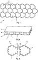
figure 5 est une vue schématique, en plan, d'une âme de structure formée d'une pluralité de pièces telles que celle représentée sur lafigure 2 . - La
figure 6 est une vue schématique, en perspective, d'une structure sandwich comprenant une âme telle que celle représentée sur lafigure 5 . - La
figure 7 illustre schématiquement un assemblage de deux pièces.
- The
figure 1 is a schematic plan view of a hexagonal piece with cells illustrating the invention. - The
figure 2 is a schematic view similar to that of thefigure 1 , without cells to highlight the characteristics of the room. - The
Figures 3 and 4 are sectional views, respectively of a tenon and a recess, of a polygonal piece. - The
figure 5 is a schematic plan view of a structural core formed of a plurality of parts such as that shown in FIG.figure 2 . - The
figure 6 is a schematic perspective view of a sandwich structure comprising a core such as that shown in FIG.figure 5 . - The
figure 7 schematically illustrates an assembly of two pieces.
La pièce 1, illustrant l'invention et représentée schématiquement sur la
Cette pièce 1 est sensiblement plane et présente une forme générale polygonale, en l'occurrence une forme générale hexagonale de côtés C1 à C6 définies, respectivement, entre des sommets A1 à A6, comme représenté sur la
Cette pièce 1 comporte une structure NIDA (c'est-à-dire en nid-d'abeilles) pourvue d'une pluralité d'alvéoles 2 de forme hexagonale. Ces alvéoles hexagonales, bien que toujours présentes dans la pièce 1, n'ont pas été représentées sur les exemples des
Chaque côté C1 à C6 de la pièce 1 de forme polygonale comporte au moins l'un des éléments d'assemblage suivants : au moins un tenon 3, au moins un évidement 4. Chacun desdits tenons 3 et chacun desdits évidements 4 de la pièce 1 sont réalisés sous forme de trapèzes, de formes respectivement complémentaires.Each side C1 to C6 of the
Dans le cadre de la présente invention, on entend par formes complémentaires le fait que les tenons 3 et les évidements 4 présentent des formes respectives permettant d'insérer un tenon 3 d'une pièce dans un évidement 4 d'une autre pièce.In the context of the present invention, complementary shapes are understood to mean that the
En plus, de la forme complémentaire, les emplacements des tenons 3 et évidements 4 sur la pièce 1 sont également complémentaires pour pouvoir réaliser un assemblage permettant de former une âme de panneau 10 telle que celle représentée sur la
Chaque trapèze 5A d'un tenon 3 s'élargit vers l'extérieur de la pièce 1, selon un sens EA, comme représenté sur la
En outre :
- les différents tenons 3 de la pièce 1 sont tous identiques, et les différents évidements 4 de la pièce 1 sont également tous identiques ; et
- chacun desdits tenons 3 et chacun desdits évidements 4 de la pièce présentent une forme de trapèze 5A, 5B isocèle.
- the
different pins 3 of thepart 1 are all identical, and thedifferent recesses 4 of thepart 1 are all all identical; and - each of said
pins 3 and each of saidrecesses 4 of the part have anisosceles trapezoid shape
De façon usuelle, un trapèze est un quadrilatère, possédant deux côtés opposés parallèles, appelés bases, et un trapèze isocèle 5A, 5B est tel que les deux bases du trapèze 5A, 5B ont une même médiatrice 6A, 6B, qui est un axe de symétrie du trapèze 5A, 5B.Usually, a trapezium is a quadrilateral, having two parallel opposite sides, called bases, and an
Ainsi, grâce à une réalisation de la forme (prédécoupée) de la pièce 1, en tenons 3 et évidements 4 complémentaires (ou en queues d'aronde positives et négatives), on peut réaliser un assemblage manuel facile et rapide de telles pièces 1, en préservant notamment les orientations de la structure NI-DA, sans ouverture des alvéoles 2, comme précisé ci-dessous. On obtient ainsi un gain très important en termes de coût et de temps d'assemblage (et donc de production). On obtient également un gain en termes d'ergonomie de poste et d'en-cours de production.Thus, thanks to an embodiment of the (pre-cut) shape of the
Comme représenté sur la
De façon similaire, comme représenté sur la
Dans un mode de réalisation préféré, la largeur IA1, par exemple 16 mm, est supérieure à la largeur lB1, par exemple 10 mm, et la largeur lA2, par exemple 31 mm, est supérieure à la largeur IB2, par exemple 25 mm, de manière à permettre une stabilité lorsqu'un tenon 3 (plus large) est inséré dans un évidement 4 (moins large). Pour permettre l'insertion, la pièce 1 est réalisée en un matériau présentant une certaine flexibilité.In a preferred embodiment, the width IA1, for example 16 mm, is greater than the width lB1, for example 10 mm, and the width lA2, for example 31 mm, is greater than the width IB2, for example 25 mm, so as to allow stability when a post 3 (wider) is inserted in a recess 4 (narrower). To allow insertion, the
Dans un mode de réalisation particulier, la largeur des tenons 3 (sur tout le tenon 3 de forme similaire à un évidement 4 le long de l'axe de symétrie) est comprise dans un domaine de largeurs défini entre 100% et 150% de la largeur des évidements 4.In a particular embodiment, the width of the tenons 3 (over the
De plus, dans un mode de réalisation préféré, la longueur LA (suivant l'axe de symétrie 6A) d'un tenon 3, par exemple 20 mm, est inférieure à la longueur LB (suivant l'axe de symétrie 6B) d'un évidement 4, par exemple 22 mm, ce qui permet d'éviter des déformations longitudinales (selon l'axe de symétrie) lorsqu'un tenon 3 est inséré dans un évidement 4.In addition, in a preferred embodiment, the length LA (along the axis of
Dans un mode de réalisation particulier, la longueur LA des tenons 3 est comprise dans un domaine de longueurs défini entre 75% et 100% de la longueur LB des évidements 4.In a particular embodiment, the length LA of the
Chaque côté C1 à C6 de la pièce 1 peut comporter un tenon 3 ou un évidement 4. Dans le cadre de la présente invention, il est également envisageable de prévoir sur un même côté Ci (i = 1,..., 6), à la fois au moins un tenon 3 et au moins un évidement 4.Each side C1 to C6 of the
Toutefois, de préférence, en particulier pour des raisons de facilité d'assemblage, chaque côté C1 à C6 de la pièce 1 est pourvu d'un seul type (tenon 3 ou évidement 4) d'élément d'assemblage. Dans ce cas, de préférence, comme représenté sur les
Dans un mode de réalisation préféré, chaque côté C1 à C6 de la pièce 1 comporte une pluralité (deux, trois,...) et de préférence deux tenons 3 identiques ou bien une pluralité (deux, trois,...) et de préférence deux évidements 4 identiques. Deux tenons 3 ou deux évidements 4 par côté C1 à C6 permettent d'obtenir une liaison stable, tout en limitant le nombre d'éléments d'assemblage, ce qui facilite la fabrication de la pièce 1, ainsi que son assemblage.In a preferred embodiment, each side C1 to C6 of the
La présente invention concerne, en outre, un procédé de fabrication à l'aide de pièces d'âme telles que la pièce précitée 1 d'une âme de panneau 10, comme représenté sur la
Une telle coque de réflecteur de satellite est, en général, constituée d'une structure sandwich composite 11 comprenant une âme 10 de type NIDA (structurale et transparente aux ondes radioélectriques) renforcée par deux peaux 12 et 13 pré-imprégnées de fibres de carbone/matrice époxy, comme représenté sur la
Pour des raisons de simplification du dessin, l'âme 10 et la structure 11 sont représentées sous forme générale rectangulaire sur les
Le procédé de fabrication de l'âme 10 comprend notamment les étapes suivantes consistant :
- a) à fabriquer, de façon usuelle, une pluralité de pièces 1 telles que la pièce 1 décrite ci-dessus, de préférence en réalisant un découpage dans une structure en nid-d'abeilles ; et
- b) pour un opérateur à assembler ensemble manuellement lesdites pièces d'âme de manière à former un élément de
structure représentant l'âme 10, l'assemblage consistant à lier ensemble des pièces d'âme adjacentes au niveau de côtés coopérants.
- a) to manufacture, in the usual manner, a plurality of
parts 1 such as thepart 1 described above, preferably by cutting into a honeycomb structure; and - b) for an operator to manually assemble said web pieces together to form a structural member representing the
web 10, the assembly of binding together adjacent web pieces at cooperating sides.
Selon l'invention, à l'étape b), pour chaque couple de côtés coopérants de deux pièces d'âme adjacentes, comme illustré sur la
L'étape b) consiste pour un opérateur :
- b1) à approcher
un tenon 3 de l'évidement 4 coopérant ; - b2) à comprimer le tenon 3 (qui est plus large que l'évidement 4) à l'aide d'une pince ;
- b3) à insérer le tenon 3 comprimé dans l'évidement 4 coopérant ; et
- b4) à réaliser un ajustage, pour bien positionner les pièces 1A et 1B l'une par rapport à l'autre.
- b1) to approach a
peg 3 of the cooperatingrecess 4; - b2) compressing the post 3 (which is wider than the recess 4) using a clamp;
- b3) inserting the
post 3 compressed in therecess 4 cooperating; and - b4) to make an adjustment, to properly position the
parts
Cette étape b) est mise en oeuvre pour l'ensemble des pièces 1 de l'âme 10.This step b) is implemented for all the
Ce mode d'assemblage permet d'obtenir des gains économiques par rapport à un procédé d'assemblage usuel nécessitant une ouverture des alvéoles. Il permet notamment de diviser par deux le temps d'assemblage. En parallèle, il permet de réduire l'effort sur le poste de travail et a un impact positif sur l'ergonomie du poste de travail : fatigue visuelle diminuée par simplification de l'imbrication.This method of assembly provides economic gains over a conventional assembly process requiring opening of the cells. It allows in particular to halve the assembly time. In parallel, it reduces the effort on the workstation and has a positive impact on the ergonomics of the workstation: reduced visual fatigue to simplify nesting.
La structure 10 en nid-d'abeilles (ou NIDA) permet notamment de renforcer la résistance d'un panneau 11 dans lequel elle est intégrée tout en garantissant une légèreté maximale.The
Après on réalise bien entendu des traitements usuels, et notamment une polymérisation, pour obtenir la structure sandwich composite définitive, en particulier une coque de réflecteur de satellite.Subsequently, of course, conventional treatments, and in particular polymerization, are carried out to obtain the final composite sandwich structure, in particular a satellite reflector shell.
Claims (12)
- Part intended for a panel core, in particular for a satellite antenna reflector, said part (1) being substantially plane and having a polygonal shape with cavities, the polygonal part (1) featuring at least one of the following assembly elements: at least one lug (3), at least one recess (4), characterised in that each side (C1 to C6) of the polygonal part (1) includes a least one of said assembly elements, in that each of said lugs (3) and each of said recesses (4) of the part (1) has a trapezoidal shape (5A, 5B), with in each case complementary shapes, the trapezium (5A) of each of said lugs (3) widening towards the outside of the part (1) and the trapezium (5B) of each of said recesses (4) widening towards the inside of the part (1), and in that each of said lugs (3) has a width defined transversely to a perpendicular bisector (6A) of the corresponding trapezium (5A), which is greater than the width of each of said recesses (4).
- Part according to claim 1, characterised in that the different lugs (3) of the part (1) are identical, and in that the different recesses (4) of the part (1) are also identical.
- Part according to any of claims 1 and 2, characterised in that each of said lugs (3) and each of said recesses (4) of the part (1) has the shape of an isosceles trapezium.
- Part according to any of claims 1 to 3, characterised in that the width of said lugs (3) is included in a defined range of widths between 100% and 150% of the width of said recesses (4).
- Part according to any of the preceding claims, characterised in that said lugs (3) have a length defined along a perpendicular bisector (6A) of the corresponding trapezium (5A), which is less than or equal to the length of said recesses (4).
- Part according to any of the preceding claims, characterised in that each side (C1 to C6) of the part (1) features at least two assembly elements (3, 4).
- Part according to claim 6, characterised in that each side (C1 to C6) of the part (1) features the same assembly elements.
- Part according to any of the preceding claims, characterised in that it has a generally hexagonal shape.
- Panel core comprising a plurality of core parts assembled together, characterised in that said core parts are like the part (1) specified in any of claims 1 to 8.
- Satellite antenna reflector, comprising a core and two skins arranged either side of the core, characterised in that said core is like the panel core (10) specified in claim 9.
- Satellite, characterised in that it features an antenna reflector like that specified in claim 10.
- Method for manufacturing a panel core, in particular for a satellite antenna reflector, using core parts such as the part (1) specified in any of claims 1 to 8, said method consisting at least of:a) producing a plurality of core parts; andb) assembling said core parts together so as to form a structural element representing said panel core (10), the assembly involving connecting together adjacent parts of the core at interacting sides, characterised in that at step b), for each pair of interacting sides of two adjacent core parts, all the lugs (3) of the side of one of said parts is inserted into all the complementary recesses (4) of the interacting side of the other of said parts.
Applications Claiming Priority (2)
| Application Number | Priority Date | Filing Date | Title |
|---|---|---|---|
| FR1400890A FR3019774A1 (en) | 2014-04-14 | 2014-04-14 | POLYGONAL PIECE WITH ALVEOLES FOR A PANEL WAVE, PARTICULARLY A SATELLITE ANTENNA REFLECTOR |
| PCT/FR2015/000074 WO2015158966A1 (en) | 2014-04-14 | 2015-04-07 | Polygonal part having cavities for a panel core, in particular of a satellite antenna reflector |
Publications (2)
| Publication Number | Publication Date |
|---|---|
| EP3131746A1 EP3131746A1 (en) | 2017-02-22 |
| EP3131746B1 true EP3131746B1 (en) | 2018-08-22 |
Family
ID=50976742
Family Applications (1)
| Application Number | Title | Priority Date | Filing Date |
|---|---|---|---|
| EP15719260.0A Not-in-force EP3131746B1 (en) | 2014-04-14 | 2015-04-07 | Polygonal part having cavities for a panel core, in particular of a satellite antenna reflector |
Country Status (5)
| Country | Link |
|---|---|
| US (1) | US10112363B2 (en) |
| EP (1) | EP3131746B1 (en) |
| CA (1) | CA2945209A1 (en) |
| FR (1) | FR3019774A1 (en) |
| WO (1) | WO2015158966A1 (en) |
Cited By (1)
| Publication number | Priority date | Publication date | Assignee | Title |
|---|---|---|---|---|
| EP4275877A1 (en) * | 2022-05-09 | 2023-11-15 | EconCore N.V. | Honeycomb with improved cell walls, their production process and equipment |
Families Citing this family (11)
| Publication number | Priority date | Publication date | Assignee | Title |
|---|---|---|---|---|
| DE102017131472A1 (en) * | 2017-09-19 | 2019-03-21 | SWAP (Sachsen) GmbH Verbundwerkstoffe | Composite panel system |
| US11192316B2 (en) * | 2018-02-16 | 2021-12-07 | Econcore N.V. | Hierarchical honeycomb core with sandwich cell walls |
| USD927222S1 (en) * | 2018-02-27 | 2021-08-10 | Cha Yau Sponge Enterprise Co., Ltd. | Hexagonal mat |
| US11059559B2 (en) | 2018-03-05 | 2021-07-13 | General Electric Company | Acoustic liners with oblique cellular structures |
| JP2021529920A (en) * | 2018-07-24 | 2021-11-04 | シュエソン ドン | Assembly configuration |
| US11047304B2 (en) | 2018-08-08 | 2021-06-29 | General Electric Company | Acoustic cores with sound-attenuating protuberances |
| US10823059B2 (en) * | 2018-10-03 | 2020-11-03 | General Electric Company | Acoustic core assemblies with mechanically joined acoustic core segments, and methods of mechanically joining acoustic core segments |
| US11434819B2 (en) | 2019-03-29 | 2022-09-06 | General Electric Company | Acoustic liners with enhanced acoustic absorption and reduced drag characteristics |
| US11668236B2 (en) | 2020-07-24 | 2023-06-06 | General Electric Company | Acoustic liners with low-frequency sound wave attenuating features |
| US11728574B2 (en) * | 2021-08-11 | 2023-08-15 | Honeywell Federal Manufacturing & Technologies, Llc | Modular base for an antenna array |
| US11965425B2 (en) | 2022-05-31 | 2024-04-23 | General Electric Company | Airfoil for a turbofan engine |
Family Cites Families (6)
| Publication number | Priority date | Publication date | Assignee | Title |
|---|---|---|---|---|
| US4287693A (en) * | 1980-03-26 | 1981-09-08 | Pawling Rubber Corporation | Interlocking rubber mat |
| US7324066B2 (en) * | 2003-07-29 | 2008-01-29 | Hitec Luxembourg S.A. | Antenna reflector |
| WO2007002442A1 (en) * | 2005-06-22 | 2007-01-04 | Kruschke Neil E | Modular surfacing system |
| DE102007026296A1 (en) * | 2007-06-06 | 2008-12-18 | Airbus Deutschland Gmbh | Honeycomb core, in particular for a sandwich component, of at least two interconnected honeycomb core parts and method for its production |
| AT510089B1 (en) * | 2010-07-13 | 2012-09-15 | Tuechler Buehnen & Textiltechnik Gmbh | FLOORING |
| US8961059B2 (en) * | 2012-09-06 | 2015-02-24 | The Boeing Company | Self-locking joints for panel structures and methods of fabricating the same |
-
2014
- 2014-04-14 FR FR1400890A patent/FR3019774A1/en not_active Withdrawn
-
2015
- 2015-04-07 US US15/303,493 patent/US10112363B2/en not_active Expired - Fee Related
- 2015-04-07 EP EP15719260.0A patent/EP3131746B1/en not_active Not-in-force
- 2015-04-07 WO PCT/FR2015/000074 patent/WO2015158966A1/en active Application Filing
- 2015-04-07 CA CA2945209A patent/CA2945209A1/en not_active Abandoned
Non-Patent Citations (1)
| Title |
|---|
| None * |
Cited By (2)
| Publication number | Priority date | Publication date | Assignee | Title |
|---|---|---|---|---|
| EP4275877A1 (en) * | 2022-05-09 | 2023-11-15 | EconCore N.V. | Honeycomb with improved cell walls, their production process and equipment |
| WO2023217688A1 (en) * | 2022-05-09 | 2023-11-16 | Econcore N.V. | Thermoplastic honeycomb with improved cell walls, production process and equipment |
Also Published As
| Publication number | Publication date |
|---|---|
| US20170043550A1 (en) | 2017-02-16 |
| CA2945209A1 (en) | 2015-10-22 |
| FR3019774A1 (en) | 2015-10-16 |
| WO2015158966A1 (en) | 2015-10-22 |
| US10112363B2 (en) | 2018-10-30 |
| EP3131746A1 (en) | 2017-02-22 |
Similar Documents
| Publication | Publication Date | Title |
|---|---|---|
| EP3131746B1 (en) | Polygonal part having cavities for a panel core, in particular of a satellite antenna reflector | |
| EP1564141B1 (en) | Aircraft seat rail and its production method | |
| EP2665597B1 (en) | Multi-branch fitting made of composite material and method of manufacturing such a multi-branch fitting | |
| EP3175283B1 (en) | Modular pair of spectacles | |
| WO2006079705A1 (en) | Arrangement of elements for producing a panel | |
| EP0887093A1 (en) | Puzzle comprising a multitude of pieces to be assembled | |
| FR2923772A1 (en) | LATERAL FRAME PART OF A VEHICLE SEAT | |
| EP2723558B1 (en) | Core of sheet structural material and assembly process | |
| WO2014032873A1 (en) | Ring for attaching a bolt to a support and assembly obtained | |
| EP3699092B1 (en) | Set of pieces assembled by a through-shaft mountable when the pieces are approximately lined up | |
| EP2767499A1 (en) | Splinting device for connecting two strut members and assembly comprising two strut members and such splinting devices | |
| CA3068214C (en) | Wind turbine mast section, wind turbine mast and assembly method | |
| FR3040053A1 (en) | DYNAMIC ANCHOR FOR LIFTING A BUILDING ELEMENT, REINFORCED | |
| FR3044723A1 (en) | MOUNTING ASSEMBLY WITH INCLINED GROOVES | |
| EP3611013B1 (en) | Method for producing spectacle arms | |
| FR3052566A1 (en) | HINGE FOR EYEWEAR MOUNT COMPRISING AT LEAST ONE INTERNAL FASTENING | |
| EP2950677B1 (en) | Decorative element comprising a number of stones which are assembled within a closed frame, comprising two decorative faces | |
| EP0914790B1 (en) | Corner connection element and multiple letter box cabinet comprising such an element | |
| FR3091493A1 (en) | Chain link | |
| CH539406A (en) | Bracelet, in particular watch bracelet, and method of manufacturing the same | |
| FR2697058A1 (en) | System for assuring assembly of furniture - comprises projecting part and hollow part which are complementary with one another which together form assembly | |
| FR2961075A3 (en) | PREFABRICATED WALL ULTRALEGERE | |
| FR2943367A1 (en) | LAMINATION-TYPE CONSTRUCTION ELEMENT AND METHOD OF MAKING SAME | |
| CA3035512A1 (en) | Reinforced dynamic lifting anchor for lifting, turning over a building element. | |
| FR3019059A1 (en) | ELEMENTARY PIECE FOR CONSTRUCTION SYSTEM BY ASSEMBLY OF SIMILAR ELEMENTARY PIECES |
Legal Events
| Date | Code | Title | Description |
|---|---|---|---|
| STAA | Information on the status of an ep patent application or granted ep patent |
Free format text: STATUS: THE INTERNATIONAL PUBLICATION HAS BEEN MADE |
|
| PUAI | Public reference made under article 153(3) epc to a published international application that has entered the european phase |
Free format text: ORIGINAL CODE: 0009012 |
|
| STAA | Information on the status of an ep patent application or granted ep patent |
Free format text: STATUS: REQUEST FOR EXAMINATION WAS MADE |
|
| 17P | Request for examination filed |
Effective date: 20161021 |
|
| AK | Designated contracting states |
Kind code of ref document: A1 Designated state(s): AL AT BE BG CH CY CZ DE DK EE ES FI FR GB GR HR HU IE IS IT LI LT LU LV MC MK MT NL NO PL PT RO RS SE SI SK SM TR |
|
| AX | Request for extension of the european patent |
Extension state: BA ME |
|
| DAV | Request for validation of the european patent (deleted) | ||
| DAX | Request for extension of the european patent (deleted) | ||
| STAA | Information on the status of an ep patent application or granted ep patent |
Free format text: STATUS: EXAMINATION IS IN PROGRESS |
|
| 17Q | First examination report despatched |
Effective date: 20170724 |
|
| GRAP | Despatch of communication of intention to grant a patent |
Free format text: ORIGINAL CODE: EPIDOSNIGR1 |
|
| STAA | Information on the status of an ep patent application or granted ep patent |
Free format text: STATUS: GRANT OF PATENT IS INTENDED |
|
| RAP1 | Party data changed (applicant data changed or rights of an application transferred) |
Owner name: ARIANEGROUP SAS |
|
| INTG | Intention to grant announced |
Effective date: 20180508 |
|
| GRAS | Grant fee paid |
Free format text: ORIGINAL CODE: EPIDOSNIGR3 |
|
| GRAA | (expected) grant |
Free format text: ORIGINAL CODE: 0009210 |
|
| STAA | Information on the status of an ep patent application or granted ep patent |
Free format text: STATUS: THE PATENT HAS BEEN GRANTED |
|
| AK | Designated contracting states |
Kind code of ref document: B1 Designated state(s): AL AT BE BG CH CY CZ DE DK EE ES FI FR GB GR HR HU IE IS IT LI LT LU LV MC MK MT NL NO PL PT RO RS SE SI SK SM TR |
|
| REG | Reference to a national code |
Ref country code: GB Ref legal event code: FG4D Free format text: NOT ENGLISH |
|
| REG | Reference to a national code |
Ref country code: CH Ref legal event code: EP |
|
| REG | Reference to a national code |
Ref country code: AT Ref legal event code: REF Ref document number: 1031962 Country of ref document: AT Kind code of ref document: T Effective date: 20180915 |
|
| REG | Reference to a national code |
Ref country code: IE Ref legal event code: FG4D Free format text: LANGUAGE OF EP DOCUMENT: FRENCH |
|
| REG | Reference to a national code |
Ref country code: DE Ref legal event code: R096 Ref document number: 602015015106 Country of ref document: DE |
|
| REG | Reference to a national code |
Ref country code: NL Ref legal event code: MP Effective date: 20180822 |
|
| REG | Reference to a national code |
Ref country code: LT Ref legal event code: MG4D |
|
| PG25 | Lapsed in a contracting state [announced via postgrant information from national office to epo] |
Ref country code: FI Free format text: LAPSE BECAUSE OF FAILURE TO SUBMIT A TRANSLATION OF THE DESCRIPTION OR TO PAY THE FEE WITHIN THE PRESCRIBED TIME-LIMIT Effective date: 20180822 Ref country code: NO Free format text: LAPSE BECAUSE OF FAILURE TO SUBMIT A TRANSLATION OF THE DESCRIPTION OR TO PAY THE FEE WITHIN THE PRESCRIBED TIME-LIMIT Effective date: 20181122 Ref country code: IS Free format text: LAPSE BECAUSE OF FAILURE TO SUBMIT A TRANSLATION OF THE DESCRIPTION OR TO PAY THE FEE WITHIN THE PRESCRIBED TIME-LIMIT Effective date: 20181222 Ref country code: NL Free format text: LAPSE BECAUSE OF FAILURE TO SUBMIT A TRANSLATION OF THE DESCRIPTION OR TO PAY THE FEE WITHIN THE PRESCRIBED TIME-LIMIT Effective date: 20180822 Ref country code: SE Free format text: LAPSE BECAUSE OF FAILURE TO SUBMIT A TRANSLATION OF THE DESCRIPTION OR TO PAY THE FEE WITHIN THE PRESCRIBED TIME-LIMIT Effective date: 20180822 Ref country code: RS Free format text: LAPSE BECAUSE OF FAILURE TO SUBMIT A TRANSLATION OF THE DESCRIPTION OR TO PAY THE FEE WITHIN THE PRESCRIBED TIME-LIMIT Effective date: 20180822 Ref country code: GR Free format text: LAPSE BECAUSE OF FAILURE TO SUBMIT A TRANSLATION OF THE DESCRIPTION OR TO PAY THE FEE WITHIN THE PRESCRIBED TIME-LIMIT Effective date: 20181123 Ref country code: LT Free format text: LAPSE BECAUSE OF FAILURE TO SUBMIT A TRANSLATION OF THE DESCRIPTION OR TO PAY THE FEE WITHIN THE PRESCRIBED TIME-LIMIT Effective date: 20180822 Ref country code: BG Free format text: LAPSE BECAUSE OF FAILURE TO SUBMIT A TRANSLATION OF THE DESCRIPTION OR TO PAY THE FEE WITHIN THE PRESCRIBED TIME-LIMIT Effective date: 20181122 |
|
| REG | Reference to a national code |
Ref country code: AT Ref legal event code: MK05 Ref document number: 1031962 Country of ref document: AT Kind code of ref document: T Effective date: 20180822 |
|
| PG25 | Lapsed in a contracting state [announced via postgrant information from national office to epo] |
Ref country code: AL Free format text: LAPSE BECAUSE OF FAILURE TO SUBMIT A TRANSLATION OF THE DESCRIPTION OR TO PAY THE FEE WITHIN THE PRESCRIBED TIME-LIMIT Effective date: 20180822 Ref country code: LV Free format text: LAPSE BECAUSE OF FAILURE TO SUBMIT A TRANSLATION OF THE DESCRIPTION OR TO PAY THE FEE WITHIN THE PRESCRIBED TIME-LIMIT Effective date: 20180822 Ref country code: HR Free format text: LAPSE BECAUSE OF FAILURE TO SUBMIT A TRANSLATION OF THE DESCRIPTION OR TO PAY THE FEE WITHIN THE PRESCRIBED TIME-LIMIT Effective date: 20180822 |
|
| PG25 | Lapsed in a contracting state [announced via postgrant information from national office to epo] |
Ref country code: ES Free format text: LAPSE BECAUSE OF FAILURE TO SUBMIT A TRANSLATION OF THE DESCRIPTION OR TO PAY THE FEE WITHIN THE PRESCRIBED TIME-LIMIT Effective date: 20180822 Ref country code: PL Free format text: LAPSE BECAUSE OF FAILURE TO SUBMIT A TRANSLATION OF THE DESCRIPTION OR TO PAY THE FEE WITHIN THE PRESCRIBED TIME-LIMIT Effective date: 20180822 Ref country code: RO Free format text: LAPSE BECAUSE OF FAILURE TO SUBMIT A TRANSLATION OF THE DESCRIPTION OR TO PAY THE FEE WITHIN THE PRESCRIBED TIME-LIMIT Effective date: 20180822 Ref country code: IT Free format text: LAPSE BECAUSE OF FAILURE TO SUBMIT A TRANSLATION OF THE DESCRIPTION OR TO PAY THE FEE WITHIN THE PRESCRIBED TIME-LIMIT Effective date: 20180822 Ref country code: CZ Free format text: LAPSE BECAUSE OF FAILURE TO SUBMIT A TRANSLATION OF THE DESCRIPTION OR TO PAY THE FEE WITHIN THE PRESCRIBED TIME-LIMIT Effective date: 20180822 Ref country code: EE Free format text: LAPSE BECAUSE OF FAILURE TO SUBMIT A TRANSLATION OF THE DESCRIPTION OR TO PAY THE FEE WITHIN THE PRESCRIBED TIME-LIMIT Effective date: 20180822 Ref country code: AT Free format text: LAPSE BECAUSE OF FAILURE TO SUBMIT A TRANSLATION OF THE DESCRIPTION OR TO PAY THE FEE WITHIN THE PRESCRIBED TIME-LIMIT Effective date: 20180822 |
|
| REG | Reference to a national code |
Ref country code: DE Ref legal event code: R097 Ref document number: 602015015106 Country of ref document: DE |
|
| PG25 | Lapsed in a contracting state [announced via postgrant information from national office to epo] |
Ref country code: DK Free format text: LAPSE BECAUSE OF FAILURE TO SUBMIT A TRANSLATION OF THE DESCRIPTION OR TO PAY THE FEE WITHIN THE PRESCRIBED TIME-LIMIT Effective date: 20180822 Ref country code: SM Free format text: LAPSE BECAUSE OF FAILURE TO SUBMIT A TRANSLATION OF THE DESCRIPTION OR TO PAY THE FEE WITHIN THE PRESCRIBED TIME-LIMIT Effective date: 20180822 Ref country code: SK Free format text: LAPSE BECAUSE OF FAILURE TO SUBMIT A TRANSLATION OF THE DESCRIPTION OR TO PAY THE FEE WITHIN THE PRESCRIBED TIME-LIMIT Effective date: 20180822 |
|
| PLBE | No opposition filed within time limit |
Free format text: ORIGINAL CODE: 0009261 |
|
| STAA | Information on the status of an ep patent application or granted ep patent |
Free format text: STATUS: NO OPPOSITION FILED WITHIN TIME LIMIT |
|
| 26N | No opposition filed |
Effective date: 20190523 |
|
| PG25 | Lapsed in a contracting state [announced via postgrant information from national office to epo] |
Ref country code: SI Free format text: LAPSE BECAUSE OF FAILURE TO SUBMIT A TRANSLATION OF THE DESCRIPTION OR TO PAY THE FEE WITHIN THE PRESCRIBED TIME-LIMIT Effective date: 20180822 |
|
| REG | Reference to a national code |
Ref country code: DE Ref legal event code: R119 Ref document number: 602015015106 Country of ref document: DE |
|
| REG | Reference to a national code |
Ref country code: CH Ref legal event code: PL |
|
| REG | Reference to a national code |
Ref country code: BE Ref legal event code: MM Effective date: 20190430 |
|
| GBPC | Gb: european patent ceased through non-payment of renewal fee |
Effective date: 20190407 |
|
| PG25 | Lapsed in a contracting state [announced via postgrant information from national office to epo] |
Ref country code: MC Free format text: LAPSE BECAUSE OF FAILURE TO SUBMIT A TRANSLATION OF THE DESCRIPTION OR TO PAY THE FEE WITHIN THE PRESCRIBED TIME-LIMIT Effective date: 20180822 Ref country code: LU Free format text: LAPSE BECAUSE OF NON-PAYMENT OF DUE FEES Effective date: 20190407 |
|
| PG25 | Lapsed in a contracting state [announced via postgrant information from national office to epo] |
Ref country code: GB Free format text: LAPSE BECAUSE OF NON-PAYMENT OF DUE FEES Effective date: 20190407 Ref country code: DE Free format text: LAPSE BECAUSE OF NON-PAYMENT OF DUE FEES Effective date: 20191101 Ref country code: CH Free format text: LAPSE BECAUSE OF NON-PAYMENT OF DUE FEES Effective date: 20190430 Ref country code: LI Free format text: LAPSE BECAUSE OF NON-PAYMENT OF DUE FEES Effective date: 20190430 |
|
| PG25 | Lapsed in a contracting state [announced via postgrant information from national office to epo] |
Ref country code: BE Free format text: LAPSE BECAUSE OF NON-PAYMENT OF DUE FEES Effective date: 20190430 Ref country code: FR Free format text: LAPSE BECAUSE OF NON-PAYMENT OF DUE FEES Effective date: 20190430 |
|
| PG25 | Lapsed in a contracting state [announced via postgrant information from national office to epo] |
Ref country code: TR Free format text: LAPSE BECAUSE OF FAILURE TO SUBMIT A TRANSLATION OF THE DESCRIPTION OR TO PAY THE FEE WITHIN THE PRESCRIBED TIME-LIMIT Effective date: 20180822 |
|
| PG25 | Lapsed in a contracting state [announced via postgrant information from national office to epo] |
Ref country code: IE Free format text: LAPSE BECAUSE OF NON-PAYMENT OF DUE FEES Effective date: 20190407 |
|
| PG25 | Lapsed in a contracting state [announced via postgrant information from national office to epo] |
Ref country code: PT Free format text: LAPSE BECAUSE OF FAILURE TO SUBMIT A TRANSLATION OF THE DESCRIPTION OR TO PAY THE FEE WITHIN THE PRESCRIBED TIME-LIMIT Effective date: 20181222 |
|
| PG25 | Lapsed in a contracting state [announced via postgrant information from national office to epo] |
Ref country code: CY Free format text: LAPSE BECAUSE OF FAILURE TO SUBMIT A TRANSLATION OF THE DESCRIPTION OR TO PAY THE FEE WITHIN THE PRESCRIBED TIME-LIMIT Effective date: 20180822 |
|
| PG25 | Lapsed in a contracting state [announced via postgrant information from national office to epo] |
Ref country code: MT Free format text: LAPSE BECAUSE OF FAILURE TO SUBMIT A TRANSLATION OF THE DESCRIPTION OR TO PAY THE FEE WITHIN THE PRESCRIBED TIME-LIMIT Effective date: 20180822 Ref country code: HU Free format text: LAPSE BECAUSE OF FAILURE TO SUBMIT A TRANSLATION OF THE DESCRIPTION OR TO PAY THE FEE WITHIN THE PRESCRIBED TIME-LIMIT; INVALID AB INITIO Effective date: 20150407 |
|
| PG25 | Lapsed in a contracting state [announced via postgrant information from national office to epo] |
Ref country code: MK Free format text: LAPSE BECAUSE OF FAILURE TO SUBMIT A TRANSLATION OF THE DESCRIPTION OR TO PAY THE FEE WITHIN THE PRESCRIBED TIME-LIMIT Effective date: 20180822 |