EP3131177B1 - Wireless power transfer system and object power supply device - Google Patents
Wireless power transfer system and object power supply device Download PDFInfo
- Publication number
- EP3131177B1 EP3131177B1 EP15768779.9A EP15768779A EP3131177B1 EP 3131177 B1 EP3131177 B1 EP 3131177B1 EP 15768779 A EP15768779 A EP 15768779A EP 3131177 B1 EP3131177 B1 EP 3131177B1
- Authority
- EP
- European Patent Office
- Prior art keywords
- power supply
- secondary coil
- primary coil
- coil
- wireless power
- Prior art date
- Legal status (The legal status is an assumption and is not a legal conclusion. Google has not performed a legal analysis and makes no representation as to the accuracy of the status listed.)
- Active
Links
- 230000005484 gravity Effects 0.000 claims description 10
- 238000010586 diagram Methods 0.000 description 25
- 230000000694 effects Effects 0.000 description 7
- 239000011800 void material Substances 0.000 description 6
- 239000003990 capacitor Substances 0.000 description 3
- 230000006698 induction Effects 0.000 description 2
- 238000005096 rolling process Methods 0.000 description 2
- 230000001419 dependent effect Effects 0.000 description 1
- 230000005684 electric field Effects 0.000 description 1
- 230000005674 electromagnetic induction Effects 0.000 description 1
- 239000000463 material Substances 0.000 description 1
- 230000000149 penetrating effect Effects 0.000 description 1
Images


Classifications
-
- B—PERFORMING OPERATIONS; TRANSPORTING
- B60—VEHICLES IN GENERAL
- B60L—PROPULSION OF ELECTRICALLY-PROPELLED VEHICLES; SUPPLYING ELECTRIC POWER FOR AUXILIARY EQUIPMENT OF ELECTRICALLY-PROPELLED VEHICLES; ELECTRODYNAMIC BRAKE SYSTEMS FOR VEHICLES IN GENERAL; MAGNETIC SUSPENSION OR LEVITATION FOR VEHICLES; MONITORING OPERATING VARIABLES OF ELECTRICALLY-PROPELLED VEHICLES; ELECTRIC SAFETY DEVICES FOR ELECTRICALLY-PROPELLED VEHICLES
- B60L53/00—Methods of charging batteries, specially adapted for electric vehicles; Charging stations or on-board charging equipment therefor; Exchange of energy storage elements in electric vehicles
- B60L53/10—Methods of charging batteries, specially adapted for electric vehicles; Charging stations or on-board charging equipment therefor; Exchange of energy storage elements in electric vehicles characterised by the energy transfer between the charging station and the vehicle
- B60L53/12—Inductive energy transfer
- B60L53/122—Circuits or methods for driving the primary coil, e.g. supplying electric power to the coil
-
- B—PERFORMING OPERATIONS; TRANSPORTING
- B60—VEHICLES IN GENERAL
- B60L—PROPULSION OF ELECTRICALLY-PROPELLED VEHICLES; SUPPLYING ELECTRIC POWER FOR AUXILIARY EQUIPMENT OF ELECTRICALLY-PROPELLED VEHICLES; ELECTRODYNAMIC BRAKE SYSTEMS FOR VEHICLES IN GENERAL; MAGNETIC SUSPENSION OR LEVITATION FOR VEHICLES; MONITORING OPERATING VARIABLES OF ELECTRICALLY-PROPELLED VEHICLES; ELECTRIC SAFETY DEVICES FOR ELECTRICALLY-PROPELLED VEHICLES
- B60L53/00—Methods of charging batteries, specially adapted for electric vehicles; Charging stations or on-board charging equipment therefor; Exchange of energy storage elements in electric vehicles
- B60L53/10—Methods of charging batteries, specially adapted for electric vehicles; Charging stations or on-board charging equipment therefor; Exchange of energy storage elements in electric vehicles characterised by the energy transfer between the charging station and the vehicle
- B60L53/14—Conductive energy transfer
- B60L53/18—Cables specially adapted for charging electric vehicles
-
- B—PERFORMING OPERATIONS; TRANSPORTING
- B60—VEHICLES IN GENERAL
- B60L—PROPULSION OF ELECTRICALLY-PROPELLED VEHICLES; SUPPLYING ELECTRIC POWER FOR AUXILIARY EQUIPMENT OF ELECTRICALLY-PROPELLED VEHICLES; ELECTRODYNAMIC BRAKE SYSTEMS FOR VEHICLES IN GENERAL; MAGNETIC SUSPENSION OR LEVITATION FOR VEHICLES; MONITORING OPERATING VARIABLES OF ELECTRICALLY-PROPELLED VEHICLES; ELECTRIC SAFETY DEVICES FOR ELECTRICALLY-PROPELLED VEHICLES
- B60L53/00—Methods of charging batteries, specially adapted for electric vehicles; Charging stations or on-board charging equipment therefor; Exchange of energy storage elements in electric vehicles
- B60L53/20—Methods of charging batteries, specially adapted for electric vehicles; Charging stations or on-board charging equipment therefor; Exchange of energy storage elements in electric vehicles characterised by converters located in the vehicle
-
- B—PERFORMING OPERATIONS; TRANSPORTING
- B60—VEHICLES IN GENERAL
- B60L—PROPULSION OF ELECTRICALLY-PROPELLED VEHICLES; SUPPLYING ELECTRIC POWER FOR AUXILIARY EQUIPMENT OF ELECTRICALLY-PROPELLED VEHICLES; ELECTRODYNAMIC BRAKE SYSTEMS FOR VEHICLES IN GENERAL; MAGNETIC SUSPENSION OR LEVITATION FOR VEHICLES; MONITORING OPERATING VARIABLES OF ELECTRICALLY-PROPELLED VEHICLES; ELECTRIC SAFETY DEVICES FOR ELECTRICALLY-PROPELLED VEHICLES
- B60L53/00—Methods of charging batteries, specially adapted for electric vehicles; Charging stations or on-board charging equipment therefor; Exchange of energy storage elements in electric vehicles
- B60L53/30—Constructional details of charging stations
- B60L53/34—Plug-like or socket-like devices specially adapted for contactless inductive charging of electric vehicles
-
- H—ELECTRICITY
- H02—GENERATION; CONVERSION OR DISTRIBUTION OF ELECTRIC POWER
- H02J—CIRCUIT ARRANGEMENTS OR SYSTEMS FOR SUPPLYING OR DISTRIBUTING ELECTRIC POWER; SYSTEMS FOR STORING ELECTRIC ENERGY
- H02J50/00—Circuit arrangements or systems for wireless supply or distribution of electric power
- H02J50/005—Mechanical details of housing or structure aiming to accommodate the power transfer means, e.g. mechanical integration of coils, antennas or transducers into emitting or receiving devices
-
- H—ELECTRICITY
- H02—GENERATION; CONVERSION OR DISTRIBUTION OF ELECTRIC POWER
- H02J—CIRCUIT ARRANGEMENTS OR SYSTEMS FOR SUPPLYING OR DISTRIBUTING ELECTRIC POWER; SYSTEMS FOR STORING ELECTRIC ENERGY
- H02J50/00—Circuit arrangements or systems for wireless supply or distribution of electric power
- H02J50/10—Circuit arrangements or systems for wireless supply or distribution of electric power using inductive coupling
-
- H—ELECTRICITY
- H02—GENERATION; CONVERSION OR DISTRIBUTION OF ELECTRIC POWER
- H02J—CIRCUIT ARRANGEMENTS OR SYSTEMS FOR SUPPLYING OR DISTRIBUTING ELECTRIC POWER; SYSTEMS FOR STORING ELECTRIC ENERGY
- H02J50/00—Circuit arrangements or systems for wireless supply or distribution of electric power
- H02J50/90—Circuit arrangements or systems for wireless supply or distribution of electric power involving detection or optimisation of position, e.g. alignment
-
- H—ELECTRICITY
- H02—GENERATION; CONVERSION OR DISTRIBUTION OF ELECTRIC POWER
- H02J—CIRCUIT ARRANGEMENTS OR SYSTEMS FOR SUPPLYING OR DISTRIBUTING ELECTRIC POWER; SYSTEMS FOR STORING ELECTRIC ENERGY
- H02J7/00—Circuit arrangements for charging or depolarising batteries or for supplying loads from batteries
- H02J7/0042—Circuit arrangements for charging or depolarising batteries or for supplying loads from batteries characterised by the mechanical construction
-
- B—PERFORMING OPERATIONS; TRANSPORTING
- B60—VEHICLES IN GENERAL
- B60L—PROPULSION OF ELECTRICALLY-PROPELLED VEHICLES; SUPPLYING ELECTRIC POWER FOR AUXILIARY EQUIPMENT OF ELECTRICALLY-PROPELLED VEHICLES; ELECTRODYNAMIC BRAKE SYSTEMS FOR VEHICLES IN GENERAL; MAGNETIC SUSPENSION OR LEVITATION FOR VEHICLES; MONITORING OPERATING VARIABLES OF ELECTRICALLY-PROPELLED VEHICLES; ELECTRIC SAFETY DEVICES FOR ELECTRICALLY-PROPELLED VEHICLES
- B60L2210/00—Converter types
- B60L2210/30—AC to DC converters
-
- B—PERFORMING OPERATIONS; TRANSPORTING
- B60—VEHICLES IN GENERAL
- B60L—PROPULSION OF ELECTRICALLY-PROPELLED VEHICLES; SUPPLYING ELECTRIC POWER FOR AUXILIARY EQUIPMENT OF ELECTRICALLY-PROPELLED VEHICLES; ELECTRODYNAMIC BRAKE SYSTEMS FOR VEHICLES IN GENERAL; MAGNETIC SUSPENSION OR LEVITATION FOR VEHICLES; MONITORING OPERATING VARIABLES OF ELECTRICALLY-PROPELLED VEHICLES; ELECTRIC SAFETY DEVICES FOR ELECTRICALLY-PROPELLED VEHICLES
- B60L2250/00—Driver interactions
- B60L2250/16—Driver interactions by display
-
- B—PERFORMING OPERATIONS; TRANSPORTING
- B60—VEHICLES IN GENERAL
- B60L—PROPULSION OF ELECTRICALLY-PROPELLED VEHICLES; SUPPLYING ELECTRIC POWER FOR AUXILIARY EQUIPMENT OF ELECTRICALLY-PROPELLED VEHICLES; ELECTRODYNAMIC BRAKE SYSTEMS FOR VEHICLES IN GENERAL; MAGNETIC SUSPENSION OR LEVITATION FOR VEHICLES; MONITORING OPERATING VARIABLES OF ELECTRICALLY-PROPELLED VEHICLES; ELECTRIC SAFETY DEVICES FOR ELECTRICALLY-PROPELLED VEHICLES
- B60L2270/00—Problem solutions or means not otherwise provided for
- B60L2270/10—Emission reduction
- B60L2270/14—Emission reduction of noise
- B60L2270/147—Emission reduction of noise electro magnetic [EMI]
-
- Y—GENERAL TAGGING OF NEW TECHNOLOGICAL DEVELOPMENTS; GENERAL TAGGING OF CROSS-SECTIONAL TECHNOLOGIES SPANNING OVER SEVERAL SECTIONS OF THE IPC; TECHNICAL SUBJECTS COVERED BY FORMER USPC CROSS-REFERENCE ART COLLECTIONS [XRACs] AND DIGESTS
- Y02—TECHNOLOGIES OR APPLICATIONS FOR MITIGATION OR ADAPTATION AGAINST CLIMATE CHANGE
- Y02T—CLIMATE CHANGE MITIGATION TECHNOLOGIES RELATED TO TRANSPORTATION
- Y02T10/00—Road transport of goods or passengers
- Y02T10/60—Other road transportation technologies with climate change mitigation effect
- Y02T10/70—Energy storage systems for electromobility, e.g. batteries
-
- Y—GENERAL TAGGING OF NEW TECHNOLOGICAL DEVELOPMENTS; GENERAL TAGGING OF CROSS-SECTIONAL TECHNOLOGIES SPANNING OVER SEVERAL SECTIONS OF THE IPC; TECHNICAL SUBJECTS COVERED BY FORMER USPC CROSS-REFERENCE ART COLLECTIONS [XRACs] AND DIGESTS
- Y02—TECHNOLOGIES OR APPLICATIONS FOR MITIGATION OR ADAPTATION AGAINST CLIMATE CHANGE
- Y02T—CLIMATE CHANGE MITIGATION TECHNOLOGIES RELATED TO TRANSPORTATION
- Y02T10/00—Road transport of goods or passengers
- Y02T10/60—Other road transportation technologies with climate change mitigation effect
- Y02T10/7072—Electromobility specific charging systems or methods for batteries, ultracapacitors, supercapacitors or double-layer capacitors
-
- Y—GENERAL TAGGING OF NEW TECHNOLOGICAL DEVELOPMENTS; GENERAL TAGGING OF CROSS-SECTIONAL TECHNOLOGIES SPANNING OVER SEVERAL SECTIONS OF THE IPC; TECHNICAL SUBJECTS COVERED BY FORMER USPC CROSS-REFERENCE ART COLLECTIONS [XRACs] AND DIGESTS
- Y02—TECHNOLOGIES OR APPLICATIONS FOR MITIGATION OR ADAPTATION AGAINST CLIMATE CHANGE
- Y02T—CLIMATE CHANGE MITIGATION TECHNOLOGIES RELATED TO TRANSPORTATION
- Y02T10/00—Road transport of goods or passengers
- Y02T10/60—Other road transportation technologies with climate change mitigation effect
- Y02T10/72—Electric energy management in electromobility
-
- Y—GENERAL TAGGING OF NEW TECHNOLOGICAL DEVELOPMENTS; GENERAL TAGGING OF CROSS-SECTIONAL TECHNOLOGIES SPANNING OVER SEVERAL SECTIONS OF THE IPC; TECHNICAL SUBJECTS COVERED BY FORMER USPC CROSS-REFERENCE ART COLLECTIONS [XRACs] AND DIGESTS
- Y02—TECHNOLOGIES OR APPLICATIONS FOR MITIGATION OR ADAPTATION AGAINST CLIMATE CHANGE
- Y02T—CLIMATE CHANGE MITIGATION TECHNOLOGIES RELATED TO TRANSPORTATION
- Y02T90/00—Enabling technologies or technologies with a potential or indirect contribution to GHG emissions mitigation
- Y02T90/10—Technologies relating to charging of electric vehicles
- Y02T90/12—Electric charging stations
-
- Y—GENERAL TAGGING OF NEW TECHNOLOGICAL DEVELOPMENTS; GENERAL TAGGING OF CROSS-SECTIONAL TECHNOLOGIES SPANNING OVER SEVERAL SECTIONS OF THE IPC; TECHNICAL SUBJECTS COVERED BY FORMER USPC CROSS-REFERENCE ART COLLECTIONS [XRACs] AND DIGESTS
- Y02—TECHNOLOGIES OR APPLICATIONS FOR MITIGATION OR ADAPTATION AGAINST CLIMATE CHANGE
- Y02T—CLIMATE CHANGE MITIGATION TECHNOLOGIES RELATED TO TRANSPORTATION
- Y02T90/00—Enabling technologies or technologies with a potential or indirect contribution to GHG emissions mitigation
- Y02T90/10—Technologies relating to charging of electric vehicles
- Y02T90/14—Plug-in electric vehicles
Definitions
- the present invention relates to a wireless power transfer system and an object power supply device that supplies electric power to an object capable of receiving power supply. This application is based on and claims priority to Japanese Patent Application No. 2014-064848 filed March 26, 2014 .
- a power supply apparatus is capable of supplying electric power to an object in a wireless manner.
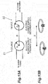
- FIGS. 13A and 13B are diagrams illustrating a concept of a wireless power transfer system.
- FIGS. 13A and 13B The concept illustrated in FIGS. 13A and 13B has been disclosed in US Patent No. 8035255 .
- electric power is supplied to a parked vehicle from a power supply apparatus.
- a vehicle has a wireless type power supply secondary coil on a bottom part thereof, and a power supply primary coil is provided below the vehicle to supply electric power to the vehicle.
- Japanese Unexamined Patent Publication No. 2012-085472 proposes to provide a vehicular charge apparatus that can implement an efficient contactless charge dispensing with a strict vehicle stop.
- the vehicular charge apparatus includes: a receiving section including a secondary coil connected to a rechargeable battery of a vehicle; a feeding section including a primary coil, installed on a ground side and configured to move toward the receiving section to fit the receiving section when opposed to the receiving section of the vehicle; positioning means for positioning the feeding section relative to the receiving section when the feeding section fits the receiving section; and feeding section power supply means disposed on the feeding section to supply power to the primary coil.
- the positioning means is inclined surface portions formed on both the receiving section and the feeding section and configured to fit each other.
- a wireless power transfer system according to the preamble of independent claim 1 is known from European Patent Application 0 874 378 A2 .
- the present disclosure describes an object power supply device capable of performing easily available power supply with a small energy loss using a simple structure.
- a wireless power transfer system of the present invention is defined in independent claim 1. Preferred embodiments are set out in the dependent claims.
- the present disclosure describes a wireless power transfer system that performs wireless power transfer, the wireless power transfer system including: a power supply primary coil capable of performing the wireless power transfer; and a power supply secondary coil capable of performing the wireless power transfer between the power supply primary coil and the power supply secondary coil, wherein the power supply secondary coil contains a secondary coil wire for the wireless power transfer and forms a secondary outer shape having a projecting surface on at least a part of the secondary outer shape, and the power supply primary coil and the power supply secondary coil are capable of performing the wireless power transfer, with the projecting surface of the secondary outer shape directed to the power supply primary coil.
- the power supply primary coil is capable of performing the wireless power transfer.
- the power supply secondary coil is capable of performing the wireless power transfer between the power supply primary coil and the power supply secondary coil.
- the power supply secondary coil contains the secondary coil wire for the wireless power transfer and forms the secondary outer shape having the projecting surface on at least a part of the secondary outer shape.
- the power supply primary coil and the power supply secondary coil are capable of performing the wireless power transfer, with the projecting surface of the secondary outer shape directed to the power supply primary coil.
- the wireless power transfer can be performed, with a relative posture between the power supply primary coil and the power supply secondary coil set to a desired posture.
- the wireless power transfer system is configured such that the secondary outer shape has a projecting curved surface on at least a part of the secondary outer shape, and the power supply primary coil and the power supply secondary coil are capable of performing the wireless power transfer, with the projecting curved surface of the secondary outer shape directed to the power supply primary coil.
- the secondary outer shape has the projecting curved surface on at least a part of the secondary outer shape.
- the power supply primary coil and the power supply secondary coil are capable of performing the wireless power transfer, with the projecting curved surface of the secondary outer shape directed to the power supply primary coil.
- the wireless power transfer can be performed, with the relative posture between the power supply primary coil and the power supply secondary coil set to the desired posture.
- the wireless power transfer system is further configured such that the secondary outer shape has a projecting curved surface on at least a part of the secondary outer shape, and a gravity center point of the power supply secondary coil is offset from a curvature center of the projecting curved surface and located on a side of the projecting curved surface.
- the secondary outer shape has the projecting curved surface on at least a part of the secondary outer shape.
- the gravity center point of the power supply secondary coil is offset from the curvature center of the projecting curved surface and located on the side of the projecting curved surface.
- the wireless power transfer can be performed, with a relative posture between the power supply primary coil and the power supply secondary coil set to a desired posture.
- the wireless power transfer system is further configured such that the power supply primary coil contains a primary coil wire for the wireless power transfer and forms a primary outer shape having a depression in at least a part of the primary outer shape, and the power supply primary coil and the power supply secondary coil are capable of performing the wireless power transfer, with the projecting surface of the secondary outer shape fit into the depression of the primary outer shape.
- the power supply primary coil contains the primary coil wire for the wireless power transfer and forms the primary outer shape having the depression in at least a part of the primary outer shape.
- the power supply primary coil and the power supply secondary coil are capable of performing the wireless power transfer, with the projecting surface of the secondary outer shape fit into the depression of the primary outer shape.
- the wireless power transfer can be performed, with a relative posture between the power supply primary coil and the power supply secondary coil set to a desired posture.
- the wireless power transfer system is further configured such that the power supply primary coil contains the primary coil wire for the wireless power transfer and forms the primary outer shape having the depression in at least the part of the primary outer shape, the depression includes a first depression and a second depression located at a center of the first depression and smaller than the first depression, and the power supply primary coil and the power supply secondary coil are capable of performing the wireless power transfer, with the projecting surface of the secondary outer shape fit into the second depression of the primary outer shape.
- the power supply primary coil contains the primary coil wire for the wireless power transfer and forms the primary outer shape having the depression in at least a part of the primary outer shape.
- the depression includes the first depression and the second depression located at the center of the first depression and smaller than the first depression.
- the power supply primary coil and the power supply secondary coil are capable of performing the wireless power transfer, with the projecting surface of the secondary outer shape fit into the second depression of the primary outer shape.
- the wireless power transfer can be performed, with a relative posture between the power supply primary coil and the power supply secondary coil set to a desired posture.
- the wireless power transfer system may include an intermediate case that supports the power supply secondary coil, wherein the secondary outer shape has a projecting curved surface with a constant radius of curvature on at least a part of the secondary outer shape, the intermediate case has an inner wall forming a recessed curved surface with a constant radius of curvature that covers the projecting curved surface of the secondary outer shape, and the power supply primary coil and the power supply secondary coil are capable of performing the wireless power transfer, with the projecting curved surface of the secondary outer shape guided by the recessed curved surface of the intermediate case and swingable.
- the intermediate case supports the power supply secondary coil.
- the secondary outer shape has the projecting curved surface with the constant radius of curvature on at least a part of the secondary outer shape.
- the intermediate case has the inner wall forming the recessed curved surface with the constant radius of curvature that covers the projecting curved surface of the secondary outer shape.
- the power supply primary coil and the power supply secondary coil are capable of performing the wireless power transfer, with the projecting curved surface of the secondary outer shape guided by the recessed curved surface of the intermediate case and swingable.
- the wireless power transfer can be performed, with a relative posture between the power supply primary coil and the power supply secondary coil set to a desired posture.
- the wireless power transfer system may include an intermediate case that supports the power supply secondary coil, wherein the secondary outer shape has a projecting curved surface with a constant radius of curvature on at least a part of the secondary outer shape, the intermediate case has an inner wall forming a recessed curved surface with a constant radius of curvature that covers the projecting curved surface of the secondary outer shape, the intermediate case contains an intermediate coil wire, and the power supply primary coil and the power supply secondary coil are capable of performing the wireless power transfer relayed by the intermediate coil wire, with the projecting curved surface of the secondary outer shape guided by the recessed curved surface of the intermediate case and swingable.
- the intermediate case supports the power supply secondary coil.
- the secondary outer shape has the projecting curved surface with the constant radius of curvature on at least a part of the secondary outer shape.
- the intermediate case has the inner wall forming the recessed curved surface with the constant radius of curvature that covers the projecting curved surface of the secondary outer shape.
- the intermediate case contains the intermediate coil wire.
- the power supply primary coil and the power supply secondary coil are capable of performing the wireless power transfer relayed by the intermediate coil wire, with the projecting curved surface of the secondary outer shape guided by the recessed curved surface of the intermediate case and swingable.
- the wireless power transfer can be performed, with a relative posture between the power supply primary coil and the power supply secondary coil set to a desired posture.
- the wireless power transfer system may be configured such that the power supply secondary coil contains a first secondary coil wire and a second secondary coil wire that are a pair of secondary coil wires, the first secondary coil wire is wound along a first virtual surface, the second secondary coil wire is wound along a second virtual surface, and the first virtual surface and the second virtual surface intersect.
- the power supply secondary coil contains the first secondary coil wire and the second secondary coil wire that are the pair of secondary coil wires.
- the first secondary coil wire is wound along the first virtual surface.
- the second secondary coil wire is wound along the second virtual surface. The first virtual surface and the second virtual surface intersect.
- the wireless power transfer can be performed, with a relative posture between the power supply primary coil and the power supply secondary coil set to a desired posture.
- An aspect of the present invention is an object power supply device that includes the above described wireless power transfer system and is capable of supplying electric power to an object in which a power receiving circuit is provided, the object power supply device also including a charging cable having an electric circuit that is electrically connectable to the power receiving circuit of the object, wherein the power supply primary coil is provided at a storage space capable of storing the object.
- the power supply primary coil is provided at the storage space capable of storing the object, and capable of performing the wireless power transfer to the power supply secondary coil.
- the charging cable has the electric circuit that is electrically connectable to the power receiving circuit of the object, and the power supply secondary coil electrically connected to the electric circuit and capable of receiving the wireless power transfer from the power supply primary coil.
- the power supply secondary coil contains the secondary coil wire for the wireless power transfer and forms the secondary outer shape having the projecting surface on at least a part of the secondary outer shape.
- the power supply primary coil and the power supply secondary coil are capable of performing the wireless power transfer, with the projecting surface of the secondary outer shape directed to the power supply primary coil.
- the wireless power transfer can be performed, with a relative posture between the power supply primary coil and the power supply secondary coil set to a desired posture.
- An aspect of the present invention is an object power supply device that includes the above described wireless power transfer system and is capable of supplying electric power to an object in which a power receiving circuit is provided, the object power supply device also including: an object support structure capable of supporting the object; and a charging cable having an electric circuit that is electrically connectable to the power receiving circuit of the object.
- the object support structure is capable of supporting the object.
- the power supply primary coil is provided at the object support structure and capable of performing the wireless power transfer to the power supply secondary coil.
- the charging cable has the electric circuit that is electrically connectable to the power receiving circuit of the object, and the power supply secondary coil electrically connected to the electric circuit and capable of receiving the wireless power transfer from the power supply primary coil.
- the power supply secondary coil contains the secondary coil wire for the wireless power transfer and forms the secondary outer shape having the projecting surface on at least a part of the secondary outer shape.
- the power supply primary coil and the power supply secondary coil are capable of performing the wireless power transfer, with the projecting surface of the secondary outer shape directed to the power supply primary coil.
- the wireless power transfer can be performed, with a relative posture between the power supply primary coil and the power supply secondary coil set to a desired posture.
- the wireless power transfer system has the following effects owing to its configuration.
- the wireless power transfer is performed, with the projecting surface formed on a part of the power supply secondary coil containing the secondary coil wire for the wireless power transfer directed to the power supply primary coil. Therefore, the wireless power transfer can be performed, with the relative posture between the power supply primary coil and the power supply secondary coil set to the desired posture.
- the wireless power transfer is performed, with the projecting curved surface formed on a part of the power supply secondary coil containing the secondary coil wire for the wireless power transfer directed to the power supply primary coil. Therefore, the wireless power transfer can be performed, with the relative posture between the power supply primary coil and the power supply secondary coil set to the desired posture.
- the wireless power transfer is performed, with the gravity center point of the power supply secondary coil offset from the curvature center of the curved surface and located on the side of the curved surface, and with the projecting curved surface formed on a part of the power supply secondary coil containing the secondary coil wire for the wireless power transfer directed to the power supply primary coil. Therefore, the wireless power transfer can be performed, with the relative posture between the power supply primary coil and the power supply secondary coil set to the desired posture.
- the wireless power transfer is performed, with the projecting surface formed on a part of the power supply secondary coil containing the secondary coil wire for the wireless power transfer directed to the power supply primary coil and fit into the depression of the power supply primary coil. Therefore, the wireless power transfer can be performed, with the relative posture between the power supply primary coil and the power supply secondary coil set to the desired posture.
- the wireless power transfer is performed, with the projecting surface formed on a part of the power supply secondary coil containing the secondary coil wire for the wireless power transfer directed to the power supply primary coil and fit into the second depression located at the center of the first depression of the power supply primary coil. Therefore, the wireless power transfer can be performed, with the relative posture between the power supply primary coil and the power supply secondary coil set to the desired posture.
- the wireless power transfer is performed, with the projecting curved surface with the constant radius of curvature formed on a part of the power supply secondary coil containing the secondary coil wire for the wireless power transfer covered by the intermediate case, and with the curved surface directed to the power supply primary coil. Therefore, the wireless power transfer can be performed, with the relative posture between the power supply primary coil and the power supply secondary coil set to the desired posture.
- the wireless power transfer is performed, with the intermediate case containing the intermediate coil wire covering the projecting curved surface with the constant radius of curvature formed on a part of the power supply secondary coil containing the secondary coil wire for the wireless power transfer, and with the curved surface directed to the power supply primary coil. Therefore, the wireless power transfer can be performed, with the relative posture between the power supply primary coil and the power supply secondary coil set to the desired posture.
- the wireless power transfer is performed, with the projecting surface formed on a part of the power supply secondary coil containing the first secondary coil wire and the second secondary coil respectively wound along the intersecting first virtual surface and second virtual surface directed to the power supply primary coil. Therefore, the wireless power transfer can be performed, with the relative posture between the power supply primary coil and the power supply secondary coil set to the desired posture.
- the object power supply device has the following effects owing to its configuration.
- the wireless power transfer is performed, with the projecting surface formed on a part of the power supply secondary coil containing the secondary coil wire for the wireless power transfer directed to the power supply primary coil provided at the storage space. Therefore, the wireless power transfer can be performed, with the relative posture between the power supply primary coil and the power supply secondary coil set to the desired posture.
- the object power supply device has the following effects owing to its configuration.
- the wireless power transfer is performed, with the projecting surface formed on a part of the power supply secondary coil containing the secondary coil wire for the wireless power transfer directed to the power supply primary coil provided at the object support structure. Therefore, the wireless power transfer can be performed, with the relative posture between the power supply primary coil and the power supply secondary coil set to the desired posture.
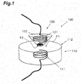
- FIG. 1 is a diagram of a wireless power transfer system according to a first example which is not claimed but is useful for understanding the present invention.
- FIG. 2 is a diagram of a wireless power transfer system according to a second example which is not claimed but is useful for understanding the present invention.
- FIG. 3 is a diagram of a wireless power transfer system according to a third example which is not claimed but is useful for understanding the present invention.
- FIG. 4 is a diagram of a wireless power transfer system according to an embodiment of the present invention.
- FIG. 5 is a diagram of a wireless power transfer system according to a fourth example which is not claimed but is useful for understanding the present invention.
- FIG. 6 is a diagram of a wireless power transfer system according to a fifth example which is not claimed but is useful for understanding the present invention.
- FIG. 7 is a diagram of a wireless power transfer system according to a sixth example which is not claimed but is useful for understanding the present invention.
- the wireless power transfer system according to the first example is a system that performs wireless power transfer.
- FIG. 1 the diagram of the wireless power transfer system according to the first example is illustrated.
- the wireless power transfer system 100 includes a power supply primary coil 110 and a power supply secondary coil 120.
- the wireless power transfer can be performed between the power supply primary coil 110 and the power supply secondary coil 120.
- the wireless power transfer can be performed from the power supply primary coil 110 to the power supply secondary coil 120.
- the wireless power transfer can be performed from the power supply secondary coil 120 to the power supply primary coil 110.
- the power supply primary coil 110 is capable of performing the wireless power transfer.
- the power supply primary coil 110 contains a primary coil wire 111 for the wireless power transfer, and forms a primary outer shape (primary shape) F1.
- the power supply primary coil 110 includes the primary coil wire 111 and a primary coil case 112.
- the primary coil wire 111 is an electric magnetic circuit in which a DC current or an AC current flows to generate a magnetic field.
- the primary coil case 112 contains the primary coil wire 111.
- the primary coil case 112 forms the primary outer shape F1.
- the primary outer shape F1 has a surface.
- the primary outer shape F1 may have a planar surface on a part of the primary outer shape F1.
- the power supply secondary coil 120 is capable of performing the wireless power transfer between the power supply primary coil 110 and the power supply secondary coil 120.
- the power supply secondary coil 120 contains a secondary coil wire 121 for the wireless power transfer, and forms a secondary outer shape (secondary shape) F2.
- the secondary outer shape F2 has a surface.
- the secondary outer shape F2 has a projecting surface on at least a part of the secondary outer shape F2.
- the power supply primary coil 110 and the power supply secondary coil 120 are capable of performing the wireless power transfer, with the projecting surface of the secondary outer shape F2 directed to the power supply primary coil 110.
- the power supply primary coil 110 and the power supply secondary coil 120 are capable of performing the wireless power transfer, with the projecting surface held by the secondary outer shape F2 directed to the planar surface held by the primary outer shape F1.
- Electric power supplied in a wireless manner from the power supply primary coil 110 can be supplied to the power supply secondary coil 120.
- FIG. 2 the diagram of the wireless power transfer system according to the second example is illustrated.
- the wireless power transfer system 100 includes a power supply primary coil 110 and a power supply secondary coil 120.
- Wireless power transfer can be performed between the power supply primary coil 110 and the power supply secondary coil 120.
- the wireless power transfer can be performed from the power supply primary coil 110 to the power supply secondary coil 120.
- the wireless power transfer can be performed from the power supply secondary coil 120 to the power supply primary coil 110.
- the power supply primary coil 110 is capable of performing the wireless power transfer.
- the power supply primary coil 110 contains a primary coil wire 111 for the wireless power transfer, and forms a primary outer shape F1.
- the power supply primary coil 110 includes the primary coil wire 111 and a primary coil case 112.
- the primary coil wire 111 is an electric magnetic circuit in which a DC current or an AC current flows to generate a magnetic field.
- the primary coil case 112 contains the primary coil wire 111.
- the primary coil case 112 forms the primary outer shape F1.
- the primary outer shape F1 has a surface.
- the primary outer shape F1 may have a planar surface on a part of the primary outer shape F1.
- the power supply secondary coil 120 is capable of performing the wireless power transfer between the power supply primary coil 110 and the power supply secondary coil 120.
- the power supply secondary coil 120 contains a secondary coil wire for the wireless power transfer, and forms a secondary outer shape F2.
- the power supply secondary coil 120 includes the secondary coil wire 121 and a secondary coil case 122.
- the secondary coil wire 121 is an electric magnetic circuit in which a DC current or an AC current flows to generate a magnetic field.
- the secondary coil case 122 contains the secondary coil wire 121.
- the secondary coil case 122 forms the secondary outer shape F2.
- the primary outer shape F1 has a surface.
- the secondary outer shape F2 has a surface.
- the secondary outer shape F2 has a projecting surface on at least a part of the secondary outer shape F2.
- the secondary outer shape F2 has a projecting curved surface on at least a part of the secondary outer shape F2.
- the secondary outer shape F2 has a spherical curved surface.
- the power supply primary coil 110 and the power supply secondary coil may be capable of performing the wireless power transfer, with the projecting curved surface of the secondary outer shape F2 directed to the power supply primary coil 110.
- the power supply primary coil 110 and the power supply secondary coil may be capable of performing the wireless power transfer, with the projecting curved surface held by the secondary outer shape F2 directed to the planar surface held by the primary outer shape F1.
- a gravity center point of the power supply secondary coil may be offset from a curvature center of the projecting curved surface and located on a side of the projecting curved surface.
- the gravity center point of the power supply secondary coil may be located between the curvature center of the projecting curved surface and the projecting curved surface.
- the power supply primary coil 110 and the power supply secondary coil 120 may be capable of performing the wireless power transfer, with the projecting curved surface of the secondary outer shape directed to the power supply primary coil 110.
- the power supply primary coil 110 and the power supply secondary coil 120 may be capable of performing the wireless power transfer, with the projecting curved surface held by the secondary outer shape F2 directed to the planar surface of the primary outer shape F1.
- the power supply secondary coil 120 has a weight on the offset position.
- the gravity center point of the power supply secondary coil 120 is located between the curvature center of the projecting curved surface and the projecting curved surface.
- Electric power supplied in a wireless manner from the power supply primary coil 110 can be supplied to the power supply secondary coil 120.
- FIG. 3 is the diagram illustrating the concept of the wireless power transfer system according to the third embodiment of the present invention.
- the wireless power transfer system 100 includes a power supply primary coil 110 and a power supply secondary coil 120.
- the wireless power transfer can be performed between the power supply primary coil 110 and the power supply secondary coil 120.
- the wireless power transfer can be performed from the power supply primary coil 110 to the power supply secondary coil 120.
- the wireless power transfer can be performed from the power supply secondary coil 120 to the power supply primary coil 110.
- the power supply primary coil 110 is capable of performing the wireless power transfer.
- the power supply primary coil 110 contains a primary coil wire 111 for the wireless power transfer, and forms a primary outer shape F1.
- the power supply primary coil 110 includes the primary coil wire 111 and a primary coil case 112.
- the primary coil wire 111 is an electric magnetic circuit in which a DC current or an AC current flows to generate a magnetic field.
- the primary coil case 112 contains the primary coil wire 111.
- the primary coil case 112 forms the primary outer shape F1.
- the primary outer shape F1 has a depression in a part of the primary outer shape F1.
- the depression may be a recessed curved surface.
- the recessed curved surface may have a radius of curvature equal to or slightly greater than a radius of curvature of a projecting curved surface held by a secondary outer shape F2 of the power supply secondary coil 120.
- the configuration of the power supply secondary coil 120 is the same as those of the wireless power transfer systems according to the first to second embodiments, the description will be omitted.
- the power supply primary coil 110 and the power supply secondary coil 120 are capable of performing the wireless power transfer, with the projecting surface held by the secondary outer shape F2 fit into the depression of the primary outer shape F1.
- Electric power supplied in a wireless manner from the power supply primary coil 110 can be supplied to the power supply secondary coil 120.
- FIG. 4 is the diagram illustrating the concept of the wireless power transfer system according to the embodiment of the present invention.
- the wireless power transfer system 100 includes a power supply primary coil 110 and a power supply secondary coil 120.
- the wireless power transfer can be performed between the power supply primary coil 110 and the power supply secondary coil 120.
- the wireless power transfer can be performed from the power supply primary coil 110 to the power supply secondary coil 120.
- the wireless power transfer can be performed from the power supply secondary coil 120 to the power supply primary coil 110.
- the power supply primary coil 110 is capable of performing the wireless power transfer.
- the power supply primary coil 110 contains a primary coil wire 111 for the wireless power transfer, and forms a primary outer shape.
- the power supply primary coil 110 includes the primary coil wire 111 and a primary coil case 112.
- the primary coil wire 111 is an electric magnetic circuit in which a DC current or an AC current flows to generate a magnetic field.
- the primary coil case 112 contains the primary coil wire 111.
- the primary coil case 112 forms the primary outer shape F1.
- the primary outer shape F1 has a depression in a part of the primary outer shape F1.
- the depression includes a first depression and a second depression.
- the second depression is located at a center of the first depression and smaller than the first depression.
- the first depression may be a recessed curved surface.
- the second depression may be a recessed curved surface.
- the recessed curved surface of the second depression may have a radius of curvature equal to or slightly greater than a radius of curvature of a projecting curved surface held by a secondary outer shape F2 of the power supply secondary coil.
- the configuration of the power supply secondary coil 120 is the same as those of the wireless power transfer systems according to the first to second embodiments, the description will be omitted.
- the power supply primary coil 110 and the power supply secondary coil 120 are capable of performing the wireless power transfer, with the projecting surface of the secondary outer shape F2 fit into the second depression of the primary outer shape F1.
- Electric power supplied in a wireless manner from the power supply primary coil 110 can be supplied to the power supply secondary coil 120.
- FIG. 5 is the diagram illustrating the concept of the wireless power transfer system according to the fifth embodiment of the present invention.
- the wireless power transfer system 100 includes a power supply primary coil 110, a power supply secondary coil 120, and an intermediate case 130.
- the wireless power transfer can be performed between the power supply primary coil 110 and the power supply secondary coil 120.
- the wireless power transfer can be performed from the power supply primary coil 110 to the power supply secondary coil 120.
- the wireless power transfer can be performed from the power supply secondary coil 120 to the power supply primary coil 110.
- the configuration of the power supply primary coil 110 is the same as those of the wireless power transfer systems according to the first to fourth embodiments, the description will be omitted.
- the configuration of the power supply secondary coil 120 is the same as that of the wireless power transfer system according to the second embodiment, the description will be omitted.
- the intermediate case 130 is a case that supports the power supply secondary coil 120.
- the intermediate case 130 has an inner wall forming a recessed curved surface with a constant radius of curvature that covers the projecting curved surface of the secondary outer shape F2.
- the intermediate case 130 forms an intermediate outer shape F3.
- the intermediate outer shape F3 may form a projecting surface on a part of the intermediate outer shape F3.
- the intermediate outer shape F3 may form a projecting curved surface on a part of the intermediate outer shape F3.
- the intermediate outer shape F3 may form a projecting curved surface with a constant radius of curvature on a part of the intermediate outer shape F3.
- the intermediate outer shape F3 may form a plane on a part of the intermediate outer shape F3.
- the power supply primary coil 110 and the power supply secondary coil 120 are capable of performing the wireless power transfer, with the projecting curved surface of the secondary outer shape F2 guided by the recessed curved surface of the intermediate case 130 and swingable.
- the power supply primary coil 110 and the power supply secondary coil 120 may be capable of performing the wireless power transfer, with the projecting surface held by the intermediate outer shape F3 directed to the power supply primary coil 110, and with the projecting curved surface of the secondary outer shape F2 guided by the recessed curved surface of the intermediate case 130 and swingable.
- the power supply primary coil 110 and the power supply secondary coil 120 may be capable of performing the wireless power transfer, with the projecting surface held by the intermediate outer shape F3 directed to the power supply primary coil 110, and with the projecting curved surface of the secondary outer shape F2 guided by the recessed curved surface of the intermediate case 130 and swingable.
- the power supply primary coil 110 and the power supply secondary coil 120 may be capable of performing the wireless power transfer, with the plane held by the intermediate outer shape F3 directed to the power supply primary coil 110, and with the projecting curved surface of the secondary outer shape F2 guided by the recessed curved surface of the intermediate case 130 and swingable.
- the power supply primary coil 110 and the power supply secondary coil 120 may be capable of performing the wireless power transfer, with the plane held by the intermediate outer shape F3 directed to a plane of the primary outer shape F1, and with the projecting curved surface of the secondary outer shape F2 guided by the recessed curved surface of the intermediate case 130 and swingable.
- Electric power supplied in a wireless manner from the power supply primary coil 110 can be supplied to the power supply secondary coil 120.
- FIG. 6 is the diagram illustrating the concept of the wireless power transfer system according to the sixth embodiment of the present invention.
- the wireless power transfer system 100 includes a power supply primary coil 110, a power supply secondary coil 120, and an intermediate case 130.
- the wireless power transfer can be performed between the power supply primary coil 110 and the power supply secondary coil 120.
- the wireless power transfer can be performed from the power supply primary coil 110 to the power supply secondary coil 120.
- the wireless power transfer can be performed from the power supply secondary coil 120 to the power supply primary coil 110.
- the configuration of the power supply primary coil 110 is the same as those of the wireless power transfer systems according to the first to fourth embodiments, the description will be omitted.
- the configuration of the power supply secondary coil 120 is the same as that of the wireless power transfer system according to the second embodiment, the description will be omitted.
- the intermediate case 130 is a case that supports the power supply secondary coil.
- the intermediate case 130 contains an intermediate coil wire 131.
- the intermediate case 130 has an inner wall forming a recessed curved surface with a constant radius of curvature that covers the projecting curved surface of the secondary outer shape.
- the intermediate case 130 forms an intermediate outer shape F3.
- the intermediate outer shape F3 may form a projecting surface on a part of the intermediate outer shape F3.
- the intermediate outer shape F3 may form a projecting curved surface on a part of the intermediate outer shape F3.
- the intermediate outer shape F3 may form a projecting curved surface with a constant radius of curvature on a part of the intermediate outer shape F3.
- the intermediate outer shape F3 may form a plane on a part of the intermediate outer shape F3.
- the power supply primary coil 110 and the power supply secondary coil 120 are capable of performing the wireless power transfer relayed by the intermediate coil wire 131.
- the power supply primary coil and the power supply secondary coil are capable of performing the wireless power transfer relayed by the intermediate coil wire, with the projecting curved surface of the secondary outer shape F2 guided by the recessed curved surface of the intermediate case 130 and swingable.
- Electric power supplied in a wireless manner from the power supply primary coil 110 can be supplied to the power supply secondary coil 120.
- the wireless power transfer system according to the sixth example is a system that performs wireless power transfer.
- FIG. 7 the diagram of the wireless power transfer system according to the sixth example is illustrated.
- the wireless power transfer system 100 includes a power supply primary coil 110 and a power supply secondary coil 120.
- the wireless power transfer can be performed between the power supply primary coil 110 and the power supply secondary coil 120.
- the wireless power transfer can be performed from the power supply primary coil 110 to the power supply secondary coil 120.
- the wireless power transfer can be performed from the power supply secondary coil 120 to the power supply primary coil 110.
- the configuration of the power supply primary coil 110 is the same as those of the wireless power transfer systems according to the first to fourth embodiments, the description will be omitted.
- the power supply secondary coil 120 is capable of performing the wireless power transfer between the power supply primary coil 110 and the power supply secondary coil 120.
- the power supply secondary coil 120 contains a pair of secondary coil wires 121 for the wireless power transfer, and forms a secondary outer shape.
- the pair of secondary coil wires 121 includes a first secondary coil wire 121a and a second secondary coil wire 121b.
- the first secondary coil wire 121a is wound along a first virtual surface A.
- the second secondary coil wire 121b is wound along a second virtual surface B.
- the first virtual surface A and the second virtual surface B intersect.
- the first virtual surface A and the second virtual surface B may be orthogonal to each other.
- the secondary outer shape F2 has a projecting surface on at least a part of the secondary outer shape F2.
- Electric power supplied in a wireless manner from the power supply primary coil 110 can be supplied to the power supply secondary coil 120.
- FIGS. 8A and 8B are diagrams of the object power supply device according to the first example.
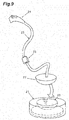
- FIG. 9 is a partial view of the object power supply device according to the third example.
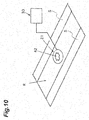
- FIG. 10 is a perspective view of the object power supply device according to the first embodiment of the present invention.
- the object power supply device is a device that can supply electric power to an object.
- the object is driven by electric power, examples of which include electric apparatuses, vehicles, movable bodies, and ships or the like.
- the object power supply device includes a charging cable 20.
- the object power supply device may include the charging cable 20 and a power supply primary coil 21.
- the object power supply device may include the charging cable 20, the power supply primary coil 21, and a drive circuit 30.
- the vehicle 10 is a movable body capable of receiving power supply.
- the vehicle 10 is a car capable of receiving power supply.
- the vehicle 10 includes a vehicle main body 11 and a power receiving circuit 12.
- the vehicle 10 may include the vehicle main body 11, the power receiving circuit 12, and a power supply plug receiver 13.
- the vehicle main body 11 is the vehicle itself.
- the vehicle is an electric car and a hybrid car or the like.
- the power receiving circuit 12 is an electric apparatus that receives electric power supplied from the outside.
- the power receiving circuit 12 charges an incorporated battery of the vehicle main body 11 with electric power supplied from the outside.
- the power supply plug receiver 13 is an electric element that is joined to a power supply plug 24 mechanically, electrically, detachably, and attachably.
- the charging cable 20 is a cable that conducts electric power to the vehicle for power supply.
- the charging cable 20 includes a power supply secondary coil 22 and an electric circuit 23.
- the charging cable 20 may include the power supply secondary coil 22, the electric circuit 23, and the power supply plug 24.
- the charging cable 20 may include the power supply secondary coil 22, the electric circuit 23, the power supply plug 24, and a converter unit 25.
- the power supply secondary coil 22 is an electric element electrically connected to the electric circuit 23 which will be described later, and capable of receiving wireless power transfer from the power supply primary coil 21.
- the power supply secondary coil can be separated from the vehicle, with the electric circuit electrically connected to the power receiving circuit.
- the power supply secondary coil can be separated from the vehicle by a distance by which the electric circuit 23 extends, with the electric circuit electrically connected to the power receiving circuit.
- electric power may be supplied in a wireless manner from the power supply primary coil 21 placed below the power supply secondary coil 22.
- electric power is supplied in a wireless manner using a magnetic field resonance type from the power supply primary coil 21 placed below the power supply secondary coil 22.
- electric power is supplied in a wireless manner using an electric field resonance type from the power supply primary coil 21 placed below the power supply secondary coil 22.
- electric power is supplied in a wireless manner using an electromagnetic induction type from the power supply primary coil 21 placed below the power supply secondary coil 22.
- the electric circuit 23 is an electric element that is electrically connectable to the power receiving circuit 12 of the vehicle 10.
- the electric circuit 23 conducts, to the power receiving circuit 12 of the vehicle 10, electric power supplied in a wireless manner to the power supply secondary coil 22.
- the electric circuit 23 is an electric cable, one end of which may be directly and electrically connected to the power receiving circuit 12 of the vehicle 10, and the other end may be electrically connected to the power supply secondary coil 22.
- the electric circuit 23 is an electric cable housed inside the vehicle 10. The electric cable is pulled to be drawn out of the vehicle 10.
- FIG. 8A it is illustrated that the electric circuit is drawn out of the vehicle 10.
- the electric circuit 23 is an electric cable, one end of which may be electrically coupled to the power receiving circuit 12 of the vehicle 10 via the power supply plug 24, and the other end may be electrically connected to the power supply secondary coil 22.
- the power supply plug 24 is an electric element that is connected to the power supply plug receiver 13 of the vehicle 10 detachably, attachably, electrically, and mechanically.
- FIG. 8B it is illustrated that the power supply plug 24 is connected to the power supply plug receiver 13 of the vehicle.
- the converter unit 25 is an electric element that converts an electrical specification of electric power supplied in a wireless manner to the power supply secondary coil 22 to an electrical specification of electric power of the power receiving circuit 12 of the vehicle 10.
- the converter unit 25 may convert a frequency, a voltage, and a phase of electric power supplied in a wireless manner to the power supply secondary coil 22 to a frequency, a voltage, and a phase of electric power of the power receiving circuit 12 of the vehicle 10.
- the converter unit 25 may rectify and convert a voltage and a phase of electric power supplied in a wireless manner to the power supply secondary coil 22 to a DC current of a predetermined voltage of electric power of the power receiving circuit 12 of the vehicle 10.
- the power supply primary coil 21 is capable of performing the wireless power transfer to the power supply secondary coil 22.
- the power supply primary coil 21 is provided at a storage space R that is a space in which the vehicle is stored, and capable of performing the wireless power transfer to the power supply secondary coil 22.
- the drive circuit 30 is a circuit that drives the power supply primary coil 21.
- the drive circuit 30 is a circuit that supplies electric power to the power supply primary coil 21 to drive the power supply primary coil 21.
- the drive circuit 30 supplies electric power to the power supply primary coil 21 to drive the power supply primary coil 21, the power supply primary coil generates a magnetic field.
- the drive circuit 30 When the drive circuit 30 appropriately drives the power supply primary coil 21, the wireless power transfer can be efficiently performed.
- the storage space R is a space for storing the vehicle 10.
- a mark 42 may be drawn at a position where the power supply primary coil 21 is provided.
- the wireless power transfer can be performed from the power supply primary coil 21 to the power supply secondary coil 22.
- FIG. 10 it is illustrated that the cross mark 42 is drawn at the position of the storage space R where the power supply primary coil 21 is provided.
- a depression 43 may be formed in a position where the power supply primary coil 21 is provided.
- the wireless power transfer can be performed from the power supply primary coil 21 to the power supply secondary coil 22.
- the depression 43 may be a hole into which a part of the secondary outer shape of the power supply secondary coil 22 is fit.
- the depression 43 may be a cone-shaped hole, a central part of which is deepened when viewed from above.
- FIG. 9 it is illustrated that the bowl-shaped depression 43 is formed in an upper part of the power supply primary coil 21.
- a predetermined signal may be output.
- a sensor provided at the storage space detects that the vehicle 10 is stored at the storage space.
- the drive circuit 30 determines that a load acting on the power supply primary coil 21 is small, it is determined that the wireless power transfer cannot be performed from the power supply primary coil 21 to the power supply secondary coil 22.
- the predetermined signal When the predetermined signal is output, a driver or an occupant of the vehicle 10 is notified of that fact by sound or display.
- the vehicle 10 enters the storage space R and stops.
- the charging cable 20 is drawn out, and the power supply secondary coil 22 is placed near the power supply primary coil 21.
- the power supply secondary coil 22 is placed in accordance with the mark 42.
- the power supply secondary coil 22 is placed in the depression 43.
- the power supply plug 24 is inserted into the power supply plug receiver 13.
- the drive circuit 30 performs driving so that the wireless power transfer is performed from the power supply primary coil 21 to the power supply secondary coil 22.
- Electric power supplied in a wireless manner from the power supply primary coil 21 to the power supply secondary coil 22 is supplied to the power receiving circuit 12 via the charging cable 20.
- an AC current having a predetermined frequency and a predetermined voltage may be supplied to the power receiving circuit 12 via the charging cable 20.
- a DC current having a predetermined voltage may be supplied to the power receiving circuit 12 via the charging cable 20.
- the charging cable 20 is tidied up.
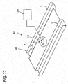
- FIG. 11 is a perspective view of the object power supply device according to the second embodiment of the present invention.
- the object power supply device is a device that can supply electric power to an object.
- the object is driven by electric power, examples of which include electric apparatuses, vehicles, movable bodies, and ships or the like.
- the object power supply device includes a charging cable 20 and an object support structure 40.
- the object power supply device may include the charging cable 20, a power supply primary coil 21, and the object support structure 40.
- the object power supply device may include the charging cable 20, the power supply primary coil 21, a drive circuit 30, and the object support structure 40.
- the configurations of the vehicle 10, the charging cable 20, the power supply primary coil 21, and the drive circuit 30 are the same as those of the object power supply device according to the first embodiment, the description will be omitted.
- the object support structure 40 is a structure that supports the vehicle 10.
- the object support structure 40 includes an object support structure main body 41.
- the object support structure 40 includes the object support structure main body 41 and a mark 42.
- the object support structure 40 includes the object support structure main body 41 and a depression 43.
- the object support structure 40 includes the object support structure main body 41, the mark 42, and the depression 43.
- FIG. 11 an example of the object support structure main body 41 is illustrated.
- the object support structure main body 41 forms a pair of left and right running surfaces S.
- the vehicle rolls wheels to the running surfaces S to load onto the object support structure 40.
- a wheel stopper is provided on the running surface S so as to prevent the wheels from rolling.
- the pair of left and right running surfaces S is a part that supports each of a pair of front and rear wheels of the vehicle 10.
- the pair of left and right running surfaces S integrally supports the vehicle 10.
- the power supply secondary coil 22 is the same as one of those of the wireless power transfer systems according to the first to seventh embodiments, the description will be omitted.
- the shape of the depression 43 is the same as the shapes of the depressions of the wireless power transfer systems according to the third to seventh embodiments, the description will be omitted.
- a predetermined signal may be output.
- a sensor provided at the object support structure 40 detects that the vehicle 10 is stored at a storage space.
- the drive circuit 30 determines that a load acting on the power supply primary coil 21 is small, it is determined that the wireless power transfer cannot be performed from the power supply primary coil 21 to the power supply secondary coil 22.
- the predetermined signal When the predetermined signal is output, a driver or an occupant of the vehicle 10 is notified of that fact by sound or display.
- FIG. 12 is a perspective view of the object power supply device according to the third example.
- the object power supply device is a device that can supply electric power to an object.
- the object is driven by electric power, examples of which include electric apparatuses, vehicles, movable bodies, and ships or the like.
- the object power supply device includes a charging cable 20 and an object support structure 40.
- the object power supply device may include the charging cable 20, a power supply primary coil 21, and the object support structure 40.
- the object power supply device may include the charging cable 20, the power supply primary coil 21, a drive circuit 30, and the object support structure 40.
- the configurations of the vehicle 10, the charging cable 20, the power supply primary coil 21, and the drive circuit 30 are the same as those of the object power supply device according to the first embodiment, the description will be omitted.
- the object support structure 40 is a structure that supports the vehicle 10.
- the object support structure 40 includes an object support structure main body 41.
- the object support structure 40 includes the object support structure main body 41 and a mark 42.
- the object support structure 40 includes the object support structure main body 41 and a depression 43.
- the object support structure 40 includes the object support structure main body 41, the mark 42, and the depression 43.
- the object support structure main body 41 may be a structure having a substantially quadrilateral shape when viewed from above that holds wheels of the vehicle 10 to support the vehicle, and may be provided with a void Q having a predetermined contour K and penetrating in a vertical direction.
- the vehicle support structure main body 41 is a so-called pallet, and provided with the void Q in a central part of the pallet when viewed from above.
- the void Q is surrounded by the contour K.
- the pallet rolls the wheels provided at a lower part thereof, and can move between a carrying device of the pallet and a parking space.
- the power supply primary coil 21 performs the wireless power transfer to the power supply secondary coil 22 via the void Q surrounded by the contour K.
- the power supply primary coil 21 may be surrounded by the contour K.
- FIG. 12 an example of the object support structure main body 41 is illustrated.
- the object support structure main body 41 forms a pair of left and right running surfaces S.
- the vehicle rolls the wheels to the running surfaces S to load onto the object support structure 40.
- a wheel stopper is provided on the running surface S so as to prevent the wheels from rolling.
- the pair of left and right running surfaces S is a part that supports each of a pair of front and rear wheels of the vehicle 10.
- the pair of left and right running surfaces S integrally supports the vehicle 10.
- the wireless power transfer system according to the embodiment of the present invention has the following effects owing to its configuration.
- the wireless power transfer is performed, with the projecting surface formed on a part of the power supply secondary coil 120 containing the secondary coil wire 121 for the wireless power transfer directed to the power supply primary coil 110. Therefore, the wireless power transfer can be performed, with a relative posture between the power supply primary coil 110 and the power supply secondary coil 120 set to a desired posture.
- the wireless power transfer is performed, with the projecting curved surface formed on a part of the power supply secondary coil 120 containing the secondary coil wire 121 for the wireless power transfer directed to the power supply primary coil 110. Therefore, the wireless power transfer can be performed, with the relative posture between the power supply primary coil 110 and the power supply secondary coil 120 set to the desired posture.
- the wireless power transfer is performed, with the gravity center point of the power supply secondary coil 120 located between the curvature center of the curved surface and the curved surface, and with the projecting curved surface formed on a part of the power supply secondary coil 120 containing the secondary coil wire 121 for the wireless power transfer directed to the power supply primary coil 110. Therefore, the wireless power transfer can be performed, with the relative posture between the power supply primary coil 110 and the power supply secondary coil 120 set to the desired posture.
- the wireless power transfer is performed, with the projecting surface formed on a part of the power supply secondary coil 120 containing the secondary coil wire 121 for the wireless power transfer directed to the power supply primary coil 110 and fit into the depression of the power supply primary coil 110. Therefore, the wireless power transfer can be performed, with the relative posture between the power supply primary coil 110 and the power supply secondary coil 120 set to the desired posture.
- the wireless power transfer is performed, with the projecting surface formed on a part of the power supply secondary coil 120 containing the secondary coil wire 121 for the wireless power transfer directed to the power supply primary coil 110 and fit into the second depression located at the center of the first depression of the power supply primary coil 110. Therefore, the wireless power transfer can be performed, with the relative posture between the power supply primary coil 110 and the power supply secondary coil 120 set to the desired posture.
- the wireless power transfer is performed, with the projecting curved surface with the constant radius of curvature formed on a part of the power supply secondary coil 120 containing the secondary coil wire 121 for the wireless power transfer covered by the intermediate case, and with the curved surface directed to the power supply primary coil 110. Therefore, the wireless power transfer can be performed, with the relative posture between the power supply primary coil 110 and the power supply secondary coil 120 set to the desired posture.
- the wireless power transfer is performed, with the intermediate case 130 containing the intermediate coil wire covering the projecting curved surface with the constant radius of curvature formed on a part of the power supply secondary coil 120 containing the secondary coil wire 121 for the wireless power transfer, and with the curved surface directed to the power supply primary coil 110. Therefore, the wireless power transfer can be performed, with the relative posture between the power supply primary coil 110 and the power supply secondary coil 120 set to the desired posture.
- the wireless power transfer is performed, with the projecting surface formed on a part of the power supply secondary coil 120 containing the first secondary coil wire 121a and the second secondary coil 121b respectively wound along the intersecting first virtual surface A and second virtual surface B directed to the power supply primary coil 110. Therefore, the wireless power transfer can be performed, with the relative posture between the power supply primary coil 110 and the power supply secondary coil 120 set to the desired posture.
- the object power supply device in which the storage space is provided according to the embodiment of the present invention has the following effects owing to its configuration.
- the wireless power transfer is performed, with the projecting surface formed on a part of the power supply secondary coil 22 containing the secondary coil wire for the wireless power transfer directed to the power supply primary coil 21 provided at the storage space R. Therefore, the wireless power transfer can be performed, with a relative posture between the power supply primary coil 21 and the power supply secondary coil 22 set to a desired posture.
- the wireless power transfer is performed, with the projecting curved surface formed on a part of the power supply secondary coil 22 containing the secondary coil wire for the wireless power transfer directed to the power supply primary coil 21 provided at the storage space R. Therefore, the wireless power transfer can be performed, with the relative posture between the power supply primary coil 21 and the power supply secondary coil 22 set to the desired posture.
- the wireless power transfer is performed, with the gravity center point of the power supply secondary coil 22 located between the curvature center of the curved surface and the curved surface, and with the projecting curved surface formed on a part of the power supply secondary coil 22 containing the secondary coil wire for the wireless power transfer directed to the power supply primary coil 21 provided at the storage space R. Therefore, the wireless power transfer can be performed, with the relative posture between the power supply primary coil 21 and the power supply secondary coil 22 set to the desired posture.
- the wireless power transfer is performed, with the projecting surface formed on a part of the power supply secondary coil 22 containing the secondary coil wire for the wireless power transfer directed to the power supply primary coil 21 provided at the storage space and fit into the depression 43 of the storage space. Therefore, the wireless power transfer can be performed, with the relative posture between the power supply primary coil 21 and the power supply secondary coil 22 set to the desired posture.
- the wireless power transfer is performed, with the projecting surface formed on a part of the power supply secondary coil 22 containing the secondary coil wire for the wireless power transfer directed to the power supply primary coil 21 provided at the storage space and fit into the second depression located at the center of the first depression of the storage space R. Therefore, the wireless power transfer can be performed, with the relative posture between the power supply primary coil 21 and the power supply secondary coil 22 set to the desired posture.
- the wireless power transfer is performed, with the projecting curved surface with the constant radius of curvature formed on a part of the power supply secondary coil 22 containing the secondary coil wire for the wireless power transfer covered by the intermediate case, and with the curved surface directed to the power supply primary coil 21 provided at the storage space R. Therefore, the wireless power transfer can be performed, with the relative posture between the power supply primary coil 21 and the power supply secondary coil 22 set to the desired posture.
- the wireless power transfer is performed, with the intermediate case containing the intermediate coil wire covering the projecting curved surface with the constant radius of curvature formed on a part of the power supply secondary coil 22 containing the secondary coil wire for the wireless power transfer, and with the curved surface directed to the power supply primary coil 21. Therefore, the wireless power transfer can be performed, with the relative posture between the power supply primary coil 21 and the power supply secondary coil 22 set to the desired posture.
- the wireless power transfer is performed, with the projecting surface formed on a part of the power supply secondary coil 22 containing the first secondary coil wire and the second secondary coil respectively wound along the intersecting first virtual surface and second virtual surface directed to the power supply primary coil 21 provided at the storage space. Therefore, the wireless power transfer can be performed, with the relative posture between the power supply primary coil 21 and the power supply secondary coil 22 set to the desired posture.
- the signal is output in a case where the wireless power transfer cannot be performed from when the vehicle 10 is stored until a predetermined period of time has elapsed. Therefore, it is possible to notify that the power supply secondary coil 22 is forgotten to be placed or that the power supply secondary coil 22 has been placed at an inappropriate place.
- the object power supply device in which the object support structure is provided according to the embodiment of the present invention has the following effects owing to its configuration.
- the wireless power transfer is performed, with the projecting surface formed on a part of the power supply secondary coil 22 containing the secondary coil wire for the wireless power transfer directed to the power supply primary coil 21 provided at the object support structure 40. Therefore, the wireless power transfer can be performed, with the relative posture between the power supply primary coil 21 and the power supply secondary coil 22 set to the desired posture.
- the wireless power transfer is performed, with the projecting curved surface formed on a part of the power supply secondary coil 22 containing the secondary coil wire for the wireless power transfer directed to the power supply primary coil 21 provided at the object support structure 40. Therefore, the wireless power transfer can be performed, with the relative posture between the power supply primary coil 21 and the power supply secondary coil 22 set to the desired posture.
- the wireless power transfer is performed, with the gravity center point of the power supply secondary coil 22 located between the curvature center of the curved surface and the curved surface, and with the projecting curved surface formed on a part of the power supply secondary coil 22 containing the secondary coil wire for the wireless power transfer directed to the power supply primary coil 21 provided at the object support structure 40. Therefore, the wireless power transfer can be performed, with the relative posture between the power supply primary coil 21 and the power supply secondary coil 22 set to the desired posture.
- the wireless power transfer is performed, with the projecting surface formed on a part of the power supply secondary coil 22 containing the secondary coil wire for the wireless power transfer directed to the power supply primary coil 21 provided at the object support structure 40 and fit into the depression 43 of the object support structure 40. Therefore, the wireless power transfer can be performed, with the relative posture between the power supply primary coil 21 and the power supply secondary coil 22 set to the desired posture.
- the wireless power transfer is performed, with the projecting surface formed on a part of the power supply secondary coil 22 containing the secondary coil wire for the wireless power transfer directed to the power supply primary coil 21 provided at the object support structure 40 and fit into the second depression located at the center of the first depression of the object support structure. Therefore, the wireless power transfer can be performed, with the relative posture between the power supply primary coil 21 and the power supply secondary coil 22 set to the desired posture.
- the wireless power transfer is performed, with the projecting curved surface with the constant radius of curvature formed on a part of the power supply secondary coil 22 containing the secondary coil wire for the wireless power transfer covered by the intermediate case, and with the curved surface directed to the power supply primary coil provided at the object support structure 40. Therefore, the wireless power transfer can be performed, with the relative posture between the power supply primary coil 21 and the power supply secondary coil 22 set to the desired posture.
- the wireless power transfer is performed, with the intermediate case containing the intermediate coil wire covering the projecting curved surface with the constant radius of curvature formed on a part of the power supply secondary coil 22 containing the secondary coil wire for the wireless power transfer, and with the curved surface directed to the power supply primary coil. Therefore, the wireless power transfer can be performed, with the relative posture between the power supply primary coil 21 and the power supply secondary coil 22 set to the desired posture.
- the wireless power transfer is performed, with the projecting surface formed on a part of the power supply secondary coil 22 containing the first secondary coil wire and the second secondary coil respectively wound along the intersecting first virtual surface and second virtual surface directed to the power supply primary coil 21 provided at the object support structure 40. Therefore, the wireless power transfer can be performed, with the relative posture between the power supply primary coil 21 and the power supply secondary coil 22 set to the desired posture.
- the signal is output in a case where the wireless power transfer cannot be performed from when the vehicle 10 is stored until a predetermined period of time has elapsed. Therefore, it is possible to notify that the power supply secondary coil 22 is forgotten to be placed or that the power supply secondary coil 22 has been placed at an inappropriate place.
- the present invention is not limited to the above-mentioned embodiments, and can be variously changed in a range not deviating from the gist of the invention.
- the present invention is not limited to this exemplary case.
- the object is electric apparatuses, vehicles, movable bodies, and ships or the like.
- the storage space is a parking space
- the object support structure is a pallet.
- the storage space is a berth
- the object support structure is a shipway.
- the storage space is a wet place
- the object support structure is a stand for the electric apparatus.
- a plate made of a material that does not affect a magnetic field may cover the void Q.
- the present invention is not limited to this exemplary case.
- the moving mechanism may include a circulation mechanism such as a box circulation parking device, a horizontal circulation parking device, a merry-go-round parking device, an elevator sliding parking device, a plane reciprocating parking device, a transporting storage parking device, and a two-stage or multiple-stage parking device.
Landscapes
- Engineering & Computer Science (AREA)
- Power Engineering (AREA)
- Transportation (AREA)
- Mechanical Engineering (AREA)
- Computer Networks & Wireless Communication (AREA)
- Charge And Discharge Circuits For Batteries Or The Like (AREA)
- Life Sciences & Earth Sciences (AREA)
- Sustainable Development (AREA)
- Sustainable Energy (AREA)
- Current-Collector Devices For Electrically Propelled Vehicles (AREA)
Description
- The present invention relates to a wireless power transfer system and an object power supply device that supplies electric power to an object capable of receiving power supply. This application is based on and claims priority to Japanese Patent Application No.
2014-064848 filed March 26, 2014 - As an object that is driven by electric power, electric apparatuses, vehicles, movable bodies, and ships or the like are used.
- It is necessary to supply electric power to an object.
- A power supply apparatus is capable of supplying electric power to an object in a wireless manner.
-
FIGS. 13A and 13B are diagrams illustrating a concept of a wireless power transfer system. - The concept illustrated in
FIGS. 13A and 13B has been disclosed inUS Patent No. 8035255 . - For example, electric power is supplied to a parked vehicle from a power supply apparatus.
- For example, such an idea has been studied that a vehicle has a wireless type power supply secondary coil on a bottom part thereof, and a power supply primary coil is provided below the vehicle to supply electric power to the vehicle.
- Japanese Unexamined Patent Publication No.
2012-085472 - A wireless power transfer system according to the preamble of independent claim 1 is known from European Patent Application
0 874 378 A2 . - When a wireless type power transfer is employed, it is desired that the electric power is supplied with a small energy loss from the power supply primary coil to the power supply secondary coil.
- When supplying electric power from the power supply primary coil to the power supply secondary coil in a wireless manner, it is also desired that usage is easy.
-
- Patent Literature 1: Japanese Unexamined Patent Publication No.
2011-60260 - Patent Literature 2: Japanese Unexamined Patent Publication No.
2011-97814 - Patent Literature 3:
US Patent No. 8035255 - Patent Literature 4:
US Patent No. 8106539 - Patent Literature 5: Japanese Unexamined Patent Publication No.
2012-085472 A - Patent Literature 6: European Patent Application
EP 0 874 378 A2 - The present disclosure describes an object power supply device capable of performing easily available power supply with a small energy loss using a simple structure.
- In order to achieve the above-mentioned purpose, a wireless power transfer system of the present invention is defined in independent claim 1. Preferred embodiments are set out in the dependent claims. The present disclosure describes a wireless power transfer system that performs wireless power transfer, the wireless power transfer system including: a power supply primary coil capable of performing the wireless power transfer; and a power supply secondary coil capable of performing the wireless power transfer between the power supply primary coil and the power supply secondary coil, wherein the power supply secondary coil contains a secondary coil wire for the wireless power transfer and forms a secondary outer shape having a projecting surface on at least a part of the secondary outer shape, and the power supply primary coil and the power supply secondary coil are capable of performing the wireless power transfer, with the projecting surface of the secondary outer shape directed to the power supply primary coil.
- Owing to the above-mentioned configuration, the power supply primary coil is capable of performing the wireless power transfer. The power supply secondary coil is capable of performing the wireless power transfer between the power supply primary coil and the power supply secondary coil. The power supply secondary coil contains the secondary coil wire for the wireless power transfer and forms the secondary outer shape having the projecting surface on at least a part of the secondary outer shape. The power supply primary coil and the power supply secondary coil are capable of performing the wireless power transfer, with the projecting surface of the secondary outer shape directed to the power supply primary coil.
- As a result, the wireless power transfer can be performed, with a relative posture between the power supply primary coil and the power supply secondary coil set to a desired posture.
- Hereinafter, a wireless power transfer system according to an embodiment of the present invention will be described.
- The wireless power transfer system according to the embodiment of the present invention is configured such that the secondary outer shape has a projecting curved surface on at least a part of the secondary outer shape, and the power supply primary coil and the power supply secondary coil are capable of performing the wireless power transfer, with the projecting curved surface of the secondary outer shape directed to the power supply primary coil.
- Owing to the above-mentioned configuration of the embodiment, the secondary outer shape has the projecting curved surface on at least a part of the secondary outer shape. The power supply primary coil and the power supply secondary coil are capable of performing the wireless power transfer, with the projecting curved surface of the secondary outer shape directed to the power supply primary coil.
- As a result, the wireless power transfer can be performed, with the relative posture between the power supply primary coil and the power supply secondary coil set to the desired posture.
- The wireless power transfer system according to the embodiment of the present invention is further configured such that the secondary outer shape has a projecting curved surface on at least a part of the secondary outer shape, and a gravity center point of the power supply secondary coil is offset from a curvature center of the projecting curved surface and located on a side of the projecting curved surface.
- Owing to the above-mentioned configuration of the embodiment, the secondary outer shape has the projecting curved surface on at least a part of the secondary outer shape.
- The gravity center point of the power supply secondary coil is offset from the curvature center of the projecting curved surface and located on the side of the projecting curved surface.
- As a result, the wireless power transfer can be performed, with a relative posture between the power supply primary coil and the power supply secondary coil set to a desired posture.
- The wireless power transfer system according to the embodiment of the present invention is further configured such that the power supply primary coil contains a primary coil wire for the wireless power transfer and forms a primary outer shape having a depression in at least a part of the primary outer shape, and the power supply primary coil and the power supply secondary coil are capable of performing the wireless power transfer, with the projecting surface of the secondary outer shape fit into the depression of the primary outer shape.
- Owing to the above-mentioned configuration of the embodiment, the power supply primary coil contains the primary coil wire for the wireless power transfer and forms the primary outer shape having the depression in at least a part of the primary outer shape. The power supply primary coil and the power supply secondary coil are capable of performing the wireless power transfer, with the projecting surface of the secondary outer shape fit into the depression of the primary outer shape.
- As a result, the wireless power transfer can be performed, with a relative posture between the power supply primary coil and the power supply secondary coil set to a desired posture.
- The wireless power transfer system according to the embodiment of the present invention is further configured such that the power supply primary coil contains the primary coil wire for the wireless power transfer and forms the primary outer shape having the depression in at least the part of the primary outer shape, the depression includes a first depression and a second depression located at a center of the first depression and smaller than the first depression, and the power supply primary coil and the power supply secondary coil are capable of performing the wireless power transfer, with the projecting surface of the secondary outer shape fit into the second depression of the primary outer shape.
- Owing to the above-mentioned configuration of the embodiment, the power supply primary coil contains the primary coil wire for the wireless power transfer and forms the primary outer shape having the depression in at least a part of the primary outer shape. The depression includes the first depression and the second depression located at the center of the first depression and smaller than the first depression. The power supply primary coil and the power supply secondary coil are capable of performing the wireless power transfer, with the projecting surface of the secondary outer shape fit into the second depression of the primary outer shape.
- As a result, the wireless power transfer can be performed, with a relative posture between the power supply primary coil and the power supply secondary coil set to a desired posture.
- The wireless power transfer system according to the embodiment of the present invention may include an intermediate case that supports the power supply secondary coil, wherein the secondary outer shape has a projecting curved surface with a constant radius of curvature on at least a part of the secondary outer shape, the intermediate case has an inner wall forming a recessed curved surface with a constant radius of curvature that covers the projecting curved surface of the secondary outer shape, and the power supply primary coil and the power supply secondary coil are capable of performing the wireless power transfer, with the projecting curved surface of the secondary outer shape guided by the recessed curved surface of the intermediate case and swingable.
- Owing to the above-mentioned configuration of the embodiment, the intermediate case supports the power supply secondary coil. The secondary outer shape has the projecting curved surface with the constant radius of curvature on at least a part of the secondary outer shape. The intermediate case has the inner wall forming the recessed curved surface with the constant radius of curvature that covers the projecting curved surface of the secondary outer shape. The power supply primary coil and the power supply secondary coil are capable of performing the wireless power transfer, with the projecting curved surface of the secondary outer shape guided by the recessed curved surface of the intermediate case and swingable.
- As a result, the wireless power transfer can be performed, with a relative posture between the power supply primary coil and the power supply secondary coil set to a desired posture.
- The wireless power transfer system according to the embodiment of the present invention may include an intermediate case that supports the power supply secondary coil, wherein the secondary outer shape has a projecting curved surface with a constant radius of curvature on at least a part of the secondary outer shape, the intermediate case has an inner wall forming a recessed curved surface with a constant radius of curvature that covers the projecting curved surface of the secondary outer shape, the intermediate case contains an intermediate coil wire, and the power supply primary coil and the power supply secondary coil are capable of performing the wireless power transfer relayed by the intermediate coil wire, with the projecting curved surface of the secondary outer shape guided by the recessed curved surface of the intermediate case and swingable.
- Owing to the above-mentioned configuration of the embodiment, the intermediate case supports the power supply secondary coil. The secondary outer shape has the projecting curved surface with the constant radius of curvature on at least a part of the secondary outer shape. The intermediate case has the inner wall forming the recessed curved surface with the constant radius of curvature that covers the projecting curved surface of the secondary outer shape. The intermediate case contains the intermediate coil wire. The power supply primary coil and the power supply secondary coil are capable of performing the wireless power transfer relayed by the intermediate coil wire, with the projecting curved surface of the secondary outer shape guided by the recessed curved surface of the intermediate case and swingable.
- As a result, the wireless power transfer can be performed, with a relative posture between the power supply primary coil and the power supply secondary coil set to a desired posture.
- The wireless power transfer system according to the embodiment of the present invention may be configured such that the power supply secondary coil contains a first secondary coil wire and a second secondary coil wire that are a pair of secondary coil wires, the first secondary coil wire is wound along a first virtual surface, the second secondary coil wire is wound along a second virtual surface, and the first virtual surface and the second virtual surface intersect.
- Owing to the above-mentioned configuration of the embodiment, the power supply secondary coil contains the first secondary coil wire and the second secondary coil wire that are the pair of secondary coil wires. The first secondary coil wire is wound along the first virtual surface. The second secondary coil wire is wound along the second virtual surface. The first virtual surface and the second virtual surface intersect.
- As a result, the wireless power transfer can be performed, with a relative posture between the power supply primary coil and the power supply secondary coil set to a desired posture.
- An aspect of the present invention is an object power supply device that includes the above described wireless power transfer system and is capable of supplying electric power to an object in which a power receiving circuit is provided, the object power supply device also including a charging cable having an electric circuit that is electrically connectable to the power receiving circuit of the object, wherein the power supply primary coil is provided at a storage space capable of storing the object.
- Owing to the above-mentioned configuration, the power supply primary coil is provided at the storage space capable of storing the object, and capable of performing the wireless power transfer to the power supply secondary coil. The charging cable has the electric circuit that is electrically connectable to the power receiving circuit of the object, and the power supply secondary coil electrically connected to the electric circuit and capable of receiving the wireless power transfer from the power supply primary coil. The power supply secondary coil contains the secondary coil wire for the wireless power transfer and forms the secondary outer shape having the projecting surface on at least a part of the secondary outer shape. The power supply primary coil and the power supply secondary coil are capable of performing the wireless power transfer, with the projecting surface of the secondary outer shape directed to the power supply primary coil.
- As a result, the wireless power transfer can be performed, with a relative posture between the power supply primary coil and the power supply secondary coil set to a desired posture.
- An aspect of the present invention is an object power supply device that includes the above described wireless power transfer system and is capable of supplying electric power to an object in which a power receiving circuit is provided, the object power supply device also including: an object support structure capable of supporting the object; and a charging cable having an electric circuit that is electrically connectable to the power receiving circuit of the object.
- Owing to the above-mentioned configuration, the object support structure is capable of supporting the object. The power supply primary coil is provided at the object support structure and capable of performing the wireless power transfer to the power supply secondary coil. The charging cable has the electric circuit that is electrically connectable to the power receiving circuit of the object, and the power supply secondary coil electrically connected to the electric circuit and capable of receiving the wireless power transfer from the power supply primary coil. The power supply secondary coil contains the secondary coil wire for the wireless power transfer and forms the secondary outer shape having the projecting surface on at least a part of the secondary outer shape. The power supply primary coil and the power supply secondary coil are capable of performing the wireless power transfer, with the projecting surface of the secondary outer shape directed to the power supply primary coil.
- As a result, the wireless power transfer can be performed, with a relative posture between the power supply primary coil and the power supply secondary coil set to a desired posture.
- As described above, the wireless power transfer system according to an aspect of the present invention has the following effects owing to its configuration.
- The wireless power transfer is performed, with the projecting surface formed on a part of the power supply secondary coil containing the secondary coil wire for the wireless power transfer directed to the power supply primary coil. Therefore, the wireless power transfer can be performed, with the relative posture between the power supply primary coil and the power supply secondary coil set to the desired posture.
- The wireless power transfer is performed, with the projecting curved surface formed on a part of the power supply secondary coil containing the secondary coil wire for the wireless power transfer directed to the power supply primary coil. Therefore, the wireless power transfer can be performed, with the relative posture between the power supply primary coil and the power supply secondary coil set to the desired posture.
- The wireless power transfer is performed, with the gravity center point of the power supply secondary coil offset from the curvature center of the curved surface and located on the side of the curved surface, and with the projecting curved surface formed on a part of the power supply secondary coil containing the secondary coil wire for the wireless power transfer directed to the power supply primary coil. Therefore, the wireless power transfer can be performed, with the relative posture between the power supply primary coil and the power supply secondary coil set to the desired posture.
- The wireless power transfer is performed, with the projecting surface formed on a part of the power supply secondary coil containing the secondary coil wire for the wireless power transfer directed to the power supply primary coil and fit into the depression of the power supply primary coil. Therefore, the wireless power transfer can be performed, with the relative posture between the power supply primary coil and the power supply secondary coil set to the desired posture.
- The wireless power transfer is performed, with the projecting surface formed on a part of the power supply secondary coil containing the secondary coil wire for the wireless power transfer directed to the power supply primary coil and fit into the second depression located at the center of the first depression of the power supply primary coil. Therefore, the wireless power transfer can be performed, with the relative posture between the power supply primary coil and the power supply secondary coil set to the desired posture.
- The wireless power transfer is performed, with the projecting curved surface with the constant radius of curvature formed on a part of the power supply secondary coil containing the secondary coil wire for the wireless power transfer covered by the intermediate case, and with the curved surface directed to the power supply primary coil. Therefore, the wireless power transfer can be performed, with the relative posture between the power supply primary coil and the power supply secondary coil set to the desired posture.
- The wireless power transfer is performed, with the intermediate case containing the intermediate coil wire covering the projecting curved surface with the constant radius of curvature formed on a part of the power supply secondary coil containing the secondary coil wire for the wireless power transfer, and with the curved surface directed to the power supply primary coil. Therefore, the wireless power transfer can be performed, with the relative posture between the power supply primary coil and the power supply secondary coil set to the desired posture.
- The wireless power transfer is performed, with the projecting surface formed on a part of the power supply secondary coil containing the first secondary coil wire and the second secondary coil respectively wound along the intersecting first virtual surface and second virtual surface directed to the power supply primary coil. Therefore, the wireless power transfer can be performed, with the relative posture between the power supply primary coil and the power supply secondary coil set to the desired posture.
- As described above, the object power supply device according to an aspect of the present invention has the following effects owing to its configuration.
- The wireless power transfer is performed, with the projecting surface formed on a part of the power supply secondary coil containing the secondary coil wire for the wireless power transfer directed to the power supply primary coil provided at the storage space. Therefore, the wireless power transfer can be performed, with the relative posture between the power supply primary coil and the power supply secondary coil set to the desired posture.
- As described above, the object power supply device according to an aspect of the present invention has the following effects owing to its configuration.
- The wireless power transfer is performed, with the projecting surface formed on a part of the power supply secondary coil containing the secondary coil wire for the wireless power transfer directed to the power supply primary coil provided at the object support structure. Therefore, the wireless power transfer can be performed, with the relative posture between the power supply primary coil and the power supply secondary coil set to the desired posture.
- Thus, it is possible to provide the wireless power transfer system and the object power supply device that are easily available with a small energy loss using a simple structure.
-
-
FIG. 1 is a diagram of a wireless power transfer system according to a first example which is not claimed but is useful for understanding the present invention. -
FIG. 2 is a diagram of a wireless power transfer system according to a second example which is not claimed but is useful for understanding the present invention. -
FIG. 3 is a diagram of a wireless power transfer system according to a third example which is not claimed but is useful for understanding the present invention. -
FIG. 4 is a diagram of a wireless power transfer system according to an embodiment of the present invention. -
FIG. 5 is a diagram of a wireless power transfer system according to a fourth example which is not claimed but is useful for understanding the present invention. -
FIG. 6 is a diagram of a wireless power transfer system according to a fifth example which is not claimed but is useful for understanding of the present invention. -
FIG. 7 is a diagram of a wireless power transfer system according to a sixth example which is not claimed but is useful for understanding the present invention. -
FIGS. 8A and 8B are diagrams of an object power supply device according to the first example. -
FIG. 9 is a partial view of the object power supply device according to the third example. -
FIG. 10 is a perspective view of the object power supply device according to the first example . -
FIG. 11 is a perspective view of an object power supply device according to the second example. -
FIG. 12 is a perspective view of an object power supply device according to the third example. -
FIGS. 13A and 13B are diagrams illustrating a concept of a wireless power transfer system. - To begin with, embodiments for practicing the present invention will be described with reference to the drawings.
-
FIG. 1 is a diagram of a wireless power transfer system according to a first example which is not claimed but is useful for understanding the present invention.FIG. 2 is a diagram of a wireless power transfer system according to a second example which is not claimed but is useful for understanding the present invention.FIG. 3 is a diagram of a wireless power transfer system according to a third example which is not claimed but is useful for understanding the present invention.FIG. 4 is a diagram of a wireless power transfer system according to an embodiment of the present invention.FIG. 5 is a diagram of a wireless power transfer system according to a fourth example which is not claimed but is useful for understanding the present invention.FIG. 6 is a diagram of a wireless power transfer system according to a fifth example which is not claimed but is useful for understanding the present invention.FIG. 7 is a diagram of a wireless power transfer system according to a sixth example which is not claimed but is useful for understanding the present invention. - The wireless power transfer system according to the first example is a system that performs wireless power transfer.
- In
FIG. 1 , the diagram of the wireless power transfer system according to the first example is illustrated. - The wireless
power transfer system 100 according to the first example includes a power supplyprimary coil 110 and a power supplysecondary coil 120. - The wireless power transfer can be performed between the power supply
primary coil 110 and the power supplysecondary coil 120. - For example, the wireless power transfer can be performed from the power supply
primary coil 110 to the power supplysecondary coil 120. - For example, the wireless power transfer can be performed from the power supply
secondary coil 120 to the power supplyprimary coil 110. - For convenience of explanation, hereinafter, an exemplary case where the wireless power transfer is performed from the power supply
primary coil 110 to the power supplysecondary coil 120 will be described. - The power supply
primary coil 110 is capable of performing the wireless power transfer. - The power supply
primary coil 110 contains aprimary coil wire 111 for the wireless power transfer, and forms a primary outer shape (primary shape) F1. - The power supply
primary coil 110 includes theprimary coil wire 111 and aprimary coil case 112. - The
primary coil wire 111 is an electric magnetic circuit in which a DC current or an AC current flows to generate a magnetic field. - The
primary coil case 112 contains theprimary coil wire 111. - The
primary coil case 112 forms the primary outer shape F1. - The primary outer shape F1 has a surface.
- The primary outer shape F1 may have a planar surface on a part of the primary outer shape F1.
- The power supply
secondary coil 120 is capable of performing the wireless power transfer between the power supplyprimary coil 110 and the power supplysecondary coil 120. - The power supply
secondary coil 120 contains asecondary coil wire 121 for the wireless power transfer, and forms a secondary outer shape (secondary shape) F2. - The secondary outer shape F2 has a surface.
- The secondary outer shape F2 has a projecting surface on at least a part of the secondary outer shape F2.
- The power supply
primary coil 110 and the power supplysecondary coil 120 are capable of performing the wireless power transfer, with the projecting surface of the secondary outer shape F2 directed to the power supplyprimary coil 110. - The power supply
primary coil 110 and the power supplysecondary coil 120 are capable of performing the wireless power transfer, with the projecting surface held by the secondary outer shape F2 directed to the planar surface held by the primary outer shape F1. - Electric power supplied in a wireless manner from the power supply
primary coil 110 can be supplied to the power supplysecondary coil 120. - When an electric current flows in the
primary coil wire 111, a magnetic field is generated in a space sandwiched between theprimary coil wire 111 and thesecondary coil wire 121, and the generated magnetic field causes an electric current to flow in thesecondary coil wire 121. - When a relative posture or position between the power supply
primary coil 110 and the power supplysecondary coil 120 is set to a predetermined posture or position, electric power can be efficiently supplied in a wireless manner from the power supplyprimary coil 110 to the power supplysecondary coil 120 with a small energy loss. - Next, the wireless power transfer system according to the second example will be described based on the drawings.
- In
FIG. 2 , the diagram of the wireless power transfer system according to the second example is illustrated. - The wireless
power transfer system 100 according to the second example includes a power supplyprimary coil 110 and a power supplysecondary coil 120. - Wireless power transfer can be performed between the power supply
primary coil 110 and the power supplysecondary coil 120. - For example, the wireless power transfer can be performed from the power supply
primary coil 110 to the power supplysecondary coil 120. - For example, the wireless power transfer can be performed from the power supply
secondary coil 120 to the power supplyprimary coil 110. - For convenience of explanation, hereinafter, the description will be provided based on the premise that the wireless power transfer is performed from the power supply
primary coil 110 to the power supplysecondary coil 120. - The power supply
primary coil 110 is capable of performing the wireless power transfer. - The power supply
primary coil 110 contains aprimary coil wire 111 for the wireless power transfer, and forms a primary outer shape F1. - The power supply
primary coil 110 includes theprimary coil wire 111 and aprimary coil case 112. - The
primary coil wire 111 is an electric magnetic circuit in which a DC current or an AC current flows to generate a magnetic field. - The
primary coil case 112 contains theprimary coil wire 111. - The
primary coil case 112 forms the primary outer shape F1. - The primary outer shape F1 has a surface.
- The primary outer shape F1 may have a planar surface on a part of the primary outer shape F1.
- The power supply
secondary coil 120 is capable of performing the wireless power transfer between the power supplyprimary coil 110 and the power supplysecondary coil 120. - The power supply
secondary coil 120 contains a secondary coil wire for the wireless power transfer, and forms a secondary outer shape F2. - The power supply
secondary coil 120 includes thesecondary coil wire 121 and asecondary coil case 122. - The
secondary coil wire 121 is an electric magnetic circuit in which a DC current or an AC current flows to generate a magnetic field. - The
secondary coil case 122 contains thesecondary coil wire 121. - The
secondary coil case 122 forms the secondary outer shape F2. - The primary outer shape F1 has a surface.
- The secondary outer shape F2 has a surface.
- The secondary outer shape F2 has a projecting surface on at least a part of the secondary outer shape F2.
- The secondary outer shape F2 has a projecting curved surface on at least a part of the secondary outer shape F2.
- In
FIG. 2 , it is illustrated that the secondary outer shape F2 has a spherical curved surface. - The power supply
primary coil 110 and the power supply secondary coil may be capable of performing the wireless power transfer, with the projecting curved surface of the secondary outer shape F2 directed to the power supplyprimary coil 110. - The power supply
primary coil 110 and the power supply secondary coil may be capable of performing the wireless power transfer, with the projecting curved surface held by the secondary outer shape F2 directed to the planar surface held by the primary outer shape F1. - A gravity center point of the power supply secondary coil may be offset from a curvature center of the projecting curved surface and located on a side of the projecting curved surface.
- As a result, the gravity center point of the power supply secondary coil may be located between the curvature center of the projecting curved surface and the projecting curved surface.
- The power supply
primary coil 110 and the power supplysecondary coil 120 may be capable of performing the wireless power transfer, with the projecting curved surface of the secondary outer shape directed to the power supplyprimary coil 110. - The power supply
primary coil 110 and the power supplysecondary coil 120 may be capable of performing the wireless power transfer, with the projecting curved surface held by the secondary outer shape F2 directed to the planar surface of the primary outer shape F1. - In
FIG. 2 , it is illustrated that the power supplysecondary coil 120 has a weight on the offset position. As a result, the gravity center point of the power supplysecondary coil 120 is located between the curvature center of the projecting curved surface and the projecting curved surface. - Electric power supplied in a wireless manner from the power supply
primary coil 110 can be supplied to the power supplysecondary coil 120. - When an electric current flows in the
primary coil wire 111, a magnetic field is generated in a space sandwiched between theprimary coil wire 111 and thesecondary coil wire 121, and the generated magnetic field causes an electric current to flow in thesecondary coil wire 121. - When a relative posture or position between the power supply
primary coil 110 and the power supplysecondary coil 120 is set to a predetermined posture or position, electric power can be efficiently supplied in a wireless manner from the power supplyprimary coil 110 to the power supplysecondary coil 120 with a small energy loss. - Next, the wireless power transfer system according to the third example will be described based on the drawings.
-
FIG. 3 is the diagram illustrating the concept of the wireless power transfer system according to the third embodiment of the present invention. - The wireless
power transfer system 100 according to the third example includes a power supplyprimary coil 110 and a power supplysecondary coil 120. - The wireless power transfer can be performed between the power supply
primary coil 110 and the power supplysecondary coil 120. - For example, the wireless power transfer can be performed from the power supply
primary coil 110 to the power supplysecondary coil 120. - For example, the wireless power transfer can be performed from the power supply
secondary coil 120 to the power supplyprimary coil 110. - For convenience of explanation, hereinafter, the description will be provided based on the premise that the wireless power transfer is performed from the power supply
primary coil 110 to the power supplysecondary coil 120. - The power supply
primary coil 110 is capable of performing the wireless power transfer. - The power supply
primary coil 110 contains aprimary coil wire 111 for the wireless power transfer, and forms a primary outer shape F1. - The power supply
primary coil 110 includes theprimary coil wire 111 and aprimary coil case 112. - The
primary coil wire 111 is an electric magnetic circuit in which a DC current or an AC current flows to generate a magnetic field. - The
primary coil case 112 contains theprimary coil wire 111. - The
primary coil case 112 forms the primary outer shape F1. - The primary outer shape F1 has a depression in a part of the primary outer shape F1.
- The depression may be a recessed curved surface.
- The recessed curved surface may have a radius of curvature equal to or slightly greater than a radius of curvature of a projecting curved surface held by a secondary outer shape F2 of the power supply
secondary coil 120. - Since the configuration of the power supply
secondary coil 120 is the same as those of the wireless power transfer systems according to the first to second embodiments, the description will be omitted. - The power supply
primary coil 110 and the power supplysecondary coil 120 are capable of performing the wireless power transfer, with the projecting surface held by the secondary outer shape F2 fit into the depression of the primary outer shape F1. - Electric power supplied in a wireless manner from the power supply
primary coil 110 can be supplied to the power supplysecondary coil 120. - When an electric current flows in the
primary coil wire 111, a magnetic field is generated in a space sandwiched between theprimary coil wire 111 and thesecondary coil wire 121, and the generated magnetic field causes an electric current to flow in thesecondary coil wire 121. - When a relative posture or position between the power supply
primary coil 110 and the power supplysecondary coil 120 is set to a predetermined posture or position, electric power can be efficiently supplied in a wireless manner from the power supplyprimary coil 110 to the power supplysecondary coil 120 with a small energy loss. - Next, the wireless power transfer system according to the embodiment of the present invention will be described based on the drawings.
-
FIG. 4 is the diagram illustrating the concept of the wireless power transfer system according to the embodiment of the present invention. - The wireless
power transfer system 100 according to the embodiment of the present invention includes a power supplyprimary coil 110 and a power supplysecondary coil 120. - The wireless power transfer can be performed between the power supply
primary coil 110 and the power supplysecondary coil 120. - For example, the wireless power transfer can be performed from the power supply
primary coil 110 to the power supplysecondary coil 120. - For example, the wireless power transfer can be performed from the power supply
secondary coil 120 to the power supplyprimary coil 110. - For convenience of explanation, hereinafter, the description will be provided based on the premise that the wireless power transfer is performed from the power supply
primary coil 110 to the power supplysecondary coil 120. - The power supply
primary coil 110 is capable of performing the wireless power transfer. - The power supply
primary coil 110 contains aprimary coil wire 111 for the wireless power transfer, and forms a primary outer shape. - The power supply
primary coil 110 includes theprimary coil wire 111 and aprimary coil case 112. - The
primary coil wire 111 is an electric magnetic circuit in which a DC current or an AC current flows to generate a magnetic field. - The
primary coil case 112 contains theprimary coil wire 111. - The
primary coil case 112 forms the primary outer shape F1. - The primary outer shape F1 has a depression in a part of the primary outer shape F1.
- The depression includes a first depression and a second depression.
- The second depression is located at a center of the first depression and smaller than the first depression.
- The first depression may be a recessed curved surface.
- The second depression may be a recessed curved surface.
- The recessed curved surface of the second depression may have a radius of curvature equal to or slightly greater than a radius of curvature of a projecting curved surface held by a secondary outer shape F2 of the power supply secondary coil.
- Since the configuration of the power supply
secondary coil 120 is the same as those of the wireless power transfer systems according to the first to second embodiments, the description will be omitted. - The power supply
primary coil 110 and the power supplysecondary coil 120 are capable of performing the wireless power transfer, with the projecting surface of the secondary outer shape F2 fit into the second depression of the primary outer shape F1. - Electric power supplied in a wireless manner from the power supply
primary coil 110 can be supplied to the power supplysecondary coil 120. - When an electric current flows in the
primary coil wire 111, a magnetic field is generated in a space sandwiched between theprimary coil wire 111 and thesecondary coil wire 121, and the generated magnetic field causes an electric current to flow in thesecondary coil wire 121. - When a relative posture or position between the power supply
primary coil 110 and the power supplysecondary coil 120 is set to a predetermined posture or position, electric power can be efficiently supplied in a wireless manner from the power supplyprimary coil 110 to the power supplysecondary coil 120 with a small energy loss. - Next, the wireless power transfer system according to the fourth example will be described based on the drawings.
-
FIG. 5 is the diagram illustrating the concept of the wireless power transfer system according to the fifth embodiment of the present invention. - The wireless
power transfer system 100 according to the fourth example includes a power supplyprimary coil 110, a power supplysecondary coil 120, and anintermediate case 130. - The wireless power transfer can be performed between the power supply
primary coil 110 and the power supplysecondary coil 120. - For example, the wireless power transfer can be performed from the power supply
primary coil 110 to the power supplysecondary coil 120. - For example, the wireless power transfer can be performed from the power supply
secondary coil 120 to the power supplyprimary coil 110. - For convenience of explanation, hereinafter, the description will be provided based on the premise that the wireless power transfer is performed from the power supply
primary coil 110 to the power supplysecondary coil 120. - Since the configuration of the power supply
primary coil 110 is the same as those of the wireless power transfer systems according to the first to fourth embodiments, the description will be omitted. - Since the configuration of the power supply
secondary coil 120 is the same as that of the wireless power transfer system according to the second embodiment, the description will be omitted. - The
intermediate case 130 is a case that supports the power supplysecondary coil 120. - The
intermediate case 130 has an inner wall forming a recessed curved surface with a constant radius of curvature that covers the projecting curved surface of the secondary outer shape F2. - The
intermediate case 130 forms an intermediate outer shape F3. - The intermediate outer shape F3 may form a projecting surface on a part of the intermediate outer shape F3.
- The intermediate outer shape F3 may form a projecting curved surface on a part of the intermediate outer shape F3.
- The intermediate outer shape F3 may form a projecting curved surface with a constant radius of curvature on a part of the intermediate outer shape F3.
- The intermediate outer shape F3 may form a plane on a part of the intermediate outer shape F3.
- The power supply
primary coil 110 and the power supplysecondary coil 120 are capable of performing the wireless power transfer, with the projecting curved surface of the secondary outer shape F2 guided by the recessed curved surface of theintermediate case 130 and swingable. - The power supply
primary coil 110 and the power supplysecondary coil 120 may be capable of performing the wireless power transfer, with the projecting surface held by the intermediate outer shape F3 directed to the power supplyprimary coil 110, and with the projecting curved surface of the secondary outer shape F2 guided by the recessed curved surface of theintermediate case 130 and swingable. - The power supply
primary coil 110 and the power supplysecondary coil 120 may be capable of performing the wireless power transfer, with the projecting surface held by the intermediate outer shape F3 directed to the power supplyprimary coil 110, and with the projecting curved surface of the secondary outer shape F2 guided by the recessed curved surface of theintermediate case 130 and swingable. - The power supply
primary coil 110 and the power supplysecondary coil 120 may be capable of performing the wireless power transfer, with the plane held by the intermediate outer shape F3 directed to the power supplyprimary coil 110, and with the projecting curved surface of the secondary outer shape F2 guided by the recessed curved surface of theintermediate case 130 and swingable. - The power supply
primary coil 110 and the power supplysecondary coil 120 may be capable of performing the wireless power transfer, with the plane held by the intermediate outer shape F3 directed to a plane of the primary outer shape F1, and with the projecting curved surface of the secondary outer shape F2 guided by the recessed curved surface of theintermediate case 130 and swingable. - Electric power supplied in a wireless manner from the power supply
primary coil 110 can be supplied to the power supplysecondary coil 120. - When an electric current flows in the
primary coil wire 111, a magnetic field is generated in a space sandwiched between theprimary coil wire 111 and thesecondary coil wire 121, and the generated magnetic field causes an electric current to flow in thesecondary coil wire 121. - When a relative posture or position between the power supply
primary coil 110 and the power supplysecondary coil 120 is set to a predetermined posture or position, electric power can be efficiently supplied in a wireless manner from the power supplyprimary coil 110 to the power supplysecondary coil 120 with a small energy loss. - Next, the wireless power transfer system according to the fifth example will be described based on the drawings.
-
FIG. 6 is the diagram illustrating the concept of the wireless power transfer system according to the sixth embodiment of the present invention. - The wireless
power transfer system 100 according to the sixth example includes a power supplyprimary coil 110, a power supplysecondary coil 120, and anintermediate case 130. - The wireless power transfer can be performed between the power supply
primary coil 110 and the power supplysecondary coil 120. - For example, the wireless power transfer can be performed from the power supply
primary coil 110 to the power supplysecondary coil 120. - For example, the wireless power transfer can be performed from the power supply
secondary coil 120 to the power supplyprimary coil 110. - For convenience of explanation, hereinafter, the description will be provided based on the premise that the wireless power transfer is performed from the power supply
primary coil 110 to the power supplysecondary coil 120. - Since the configuration of the power supply
primary coil 110 is the same as those of the wireless power transfer systems according to the first to fourth embodiments, the description will be omitted. - Since the configuration of the power supply
secondary coil 120 is the same as that of the wireless power transfer system according to the second embodiment, the description will be omitted. - The
intermediate case 130 is a case that supports the power supply secondary coil. - The
intermediate case 130 contains anintermediate coil wire 131. - The
intermediate case 130 has an inner wall forming a recessed curved surface with a constant radius of curvature that covers the projecting curved surface of the secondary outer shape. - The
intermediate case 130 forms an intermediate outer shape F3. - The intermediate outer shape F3 may form a projecting surface on a part of the intermediate outer shape F3.
- The intermediate outer shape F3 may form a projecting curved surface on a part of the intermediate outer shape F3.
- The intermediate outer shape F3 may form a projecting curved surface with a constant radius of curvature on a part of the intermediate outer shape F3.
- The intermediate outer shape F3 may form a plane on a part of the intermediate outer shape F3.
- The power supply
primary coil 110 and the power supplysecondary coil 120 are capable of performing the wireless power transfer relayed by theintermediate coil wire 131. - The power supply primary coil and the power supply secondary coil are capable of performing the wireless power transfer relayed by the intermediate coil wire, with the projecting curved surface of the secondary outer shape F2 guided by the recessed curved surface of the
intermediate case 130 and swingable. - Electric power supplied in a wireless manner from the power supply
primary coil 110 can be supplied to the power supplysecondary coil 120. - When an electric current flows in the
primary coil wire 111, a magnetic field is generated in a space sandwiched between theprimary coil wire 111, thesecondary coil wire 121, and theintermediate coil wire 131, and the generated magnetic field causes an electric current to flow in thesecondary coil wire 121. - When a relative posture or position between the power supply
primary coil 110 and the power supplysecondary coil 120 is set to a predetermined posture or position, electric power can be efficiently supplied in a wireless manner from the power supplyprimary coil 110 to the power supplysecondary coil 120 with a small energy loss. - The wireless power transfer system according to the sixth example is a system that performs wireless power transfer.
- In
FIG. 7 , the diagram of the wireless power transfer system according to the sixth example is illustrated. - The wireless
power transfer system 100 according to the sixth example includes a power supplyprimary coil 110 and a power supplysecondary coil 120. - The wireless power transfer can be performed between the power supply
primary coil 110 and the power supplysecondary coil 120. - For example, the wireless power transfer can be performed from the power supply
primary coil 110 to the power supplysecondary coil 120. - For example, the wireless power transfer can be performed from the power supply
secondary coil 120 to the power supplyprimary coil 110. - For convenience of explanation, hereinafter, the description will be provided based on the premise that the wireless power transfer is performed from the power supply
primary coil 110 to the power supplysecondary coil 120. - Since the configuration of the power supply
primary coil 110 is the same as those of the wireless power transfer systems according to the first to fourth embodiments, the description will be omitted. - The power supply
secondary coil 120 is capable of performing the wireless power transfer between the power supplyprimary coil 110 and the power supplysecondary coil 120. - The power supply
secondary coil 120 contains a pair ofsecondary coil wires 121 for the wireless power transfer, and forms a secondary outer shape. - The pair of
secondary coil wires 121 includes a firstsecondary coil wire 121a and a secondsecondary coil wire 121b. - The first
secondary coil wire 121a is wound along a first virtual surface A. - The second
secondary coil wire 121b is wound along a second virtual surface B. - The first virtual surface A and the second virtual surface B intersect.
- The first virtual surface A and the second virtual surface B may be orthogonal to each other.
- The secondary outer shape F2 has a projecting surface on at least a part of the secondary outer shape F2.
- Since the configuration of the secondary outer shape F2 is the same as those of the wireless power transfer systems according to the first to sixth embodiments, the description will be omitted.
- Electric power supplied in a wireless manner from the power supply
primary coil 110 can be supplied to the power supplysecondary coil 120. - When an electric current flows in the
primary coil wire 111, a magnetic field is generated in a space sandwiched between theprimary coil wire 111 and thesecondary coil wire 121, and the generated magnetic field causes an electric current to flow in the firstsecondary coil wire 121a and the secondsecondary coil wire 121b. - When a relative posture or position between the power supply
primary coil 110 and the power supplysecondary coil 120 is set to a predetermined posture or position, electric power can be efficiently supplied in a wireless manner from the power supplyprimary coil 110 to the power supplysecondary coil 120 with a small energy loss. - Next, an object power supply device for practicing the present invention will be described with reference to the drawings.
- First, an object power supply device according to the first example useful for understanding the present invention will be described based on the drawings.
-
FIGS. 8A and 8B are diagrams of the object power supply device according to the first example.FIG. 9 is a partial view of the object power supply device according to the third example.FIG. 10 is a perspective view of the object power supply device according to the first embodiment of the present invention. - The object power supply device according to the first example is a device that can supply electric power to an object.
- The object is driven by electric power, examples of which include electric apparatuses, vehicles, movable bodies, and ships or the like.
- For convenience of explanation, hereinafter, the description will be provided based on the assumption that the object is a vehicle.
- The object power supply device according to the first example includes a charging
cable 20. - The object power supply device according to the first example may include the charging
cable 20 and a power supplyprimary coil 21. - The object power supply device according to the first example may include the charging
cable 20, the power supplyprimary coil 21, and adrive circuit 30. - The
vehicle 10 is a movable body capable of receiving power supply. - For example, the
vehicle 10 is a car capable of receiving power supply. - The
vehicle 10 includes a vehicle main body 11 and apower receiving circuit 12. - The
vehicle 10 may include the vehicle main body 11, thepower receiving circuit 12, and a powersupply plug receiver 13. - The vehicle main body 11 is the vehicle itself.
- For example, the vehicle is an electric car and a hybrid car or the like.
- The
power receiving circuit 12 is an electric apparatus that receives electric power supplied from the outside. - For example, the
power receiving circuit 12 charges an incorporated battery of the vehicle main body 11 with electric power supplied from the outside. - The power
supply plug receiver 13 is an electric element that is joined to apower supply plug 24 mechanically, electrically, detachably, and attachably. - The charging
cable 20 is a cable that conducts electric power to the vehicle for power supply. - The charging
cable 20 includes a power supplysecondary coil 22 and anelectric circuit 23. - The charging
cable 20 may include the power supplysecondary coil 22, theelectric circuit 23, and thepower supply plug 24. - The charging
cable 20 may include the power supplysecondary coil 22, theelectric circuit 23, thepower supply plug 24, and aconverter unit 25. - The power supply
secondary coil 22 is an electric element electrically connected to theelectric circuit 23 which will be described later, and capable of receiving wireless power transfer from the power supplyprimary coil 21. - The power supply secondary coil can be separated from the vehicle, with the electric circuit electrically connected to the power receiving circuit.
- The power supply secondary coil can be separated from the vehicle by a distance by which the
electric circuit 23 extends, with the electric circuit electrically connected to the power receiving circuit. - To the power supply
secondary coil 22, electric power may be supplied in a wireless manner from the power supplyprimary coil 21 placed below the power supplysecondary coil 22. - For example, to the power supply
secondary coil 22, electric power is supplied in a wireless manner using a magnetic field resonance type from the power supplyprimary coil 21 placed below the power supplysecondary coil 22. - For example, to the power supply
secondary coil 22, electric power is supplied in a wireless manner using an electric field resonance type from the power supplyprimary coil 21 placed below the power supplysecondary coil 22. - For example, to the power supply
secondary coil 22, electric power is supplied in a wireless manner using an electromagnetic induction type from the power supplyprimary coil 21 placed below the power supplysecondary coil 22. - Since the configurations of the power supply
primary coil 21 and the power supplysecondary coil 22 are the same as one of those of the wirelesspower transfer systems 100 according to the first to seventh embodiments, the description will be omitted. - The
electric circuit 23 is an electric element that is electrically connectable to thepower receiving circuit 12 of thevehicle 10. - The
electric circuit 23 conducts, to thepower receiving circuit 12 of thevehicle 10, electric power supplied in a wireless manner to the power supplysecondary coil 22. - The
electric circuit 23 is an electric cable, one end of which may be directly and electrically connected to thepower receiving circuit 12 of thevehicle 10, and the other end may be electrically connected to the power supplysecondary coil 22. - For example, the
electric circuit 23 is an electric cable housed inside thevehicle 10. The electric cable is pulled to be drawn out of thevehicle 10. - In
FIG. 8A , it is illustrated that the electric circuit is drawn out of thevehicle 10. - The
electric circuit 23 is an electric cable, one end of which may be electrically coupled to thepower receiving circuit 12 of thevehicle 10 via thepower supply plug 24, and the other end may be electrically connected to the power supplysecondary coil 22. - The
power supply plug 24 is an electric element that is connected to the powersupply plug receiver 13 of thevehicle 10 detachably, attachably, electrically, and mechanically. - In
FIG. 8B , it is illustrated that thepower supply plug 24 is connected to the powersupply plug receiver 13 of the vehicle. - The
converter unit 25 is an electric element that converts an electrical specification of electric power supplied in a wireless manner to the power supplysecondary coil 22 to an electrical specification of electric power of thepower receiving circuit 12 of thevehicle 10. - The
converter unit 25 may convert a frequency, a voltage, and a phase of electric power supplied in a wireless manner to the power supplysecondary coil 22 to a frequency, a voltage, and a phase of electric power of thepower receiving circuit 12 of thevehicle 10. - The
converter unit 25 may rectify and convert a voltage and a phase of electric power supplied in a wireless manner to the power supplysecondary coil 22 to a DC current of a predetermined voltage of electric power of thepower receiving circuit 12 of thevehicle 10. - The power supply
primary coil 21 is capable of performing the wireless power transfer to the power supplysecondary coil 22. - The power supply
primary coil 21 is provided at a storage space R that is a space in which the vehicle is stored, and capable of performing the wireless power transfer to the power supplysecondary coil 22. - When an electric current flows in the power supply
primary coil 21, a magnetic field is generated in the space, and an induction current by the magnetic field is generated in the power supplysecondary coil 22 that exists in the magnetic field. - For example, when an alternating current flows in the power supply
primary coil 21, a magnetic field is generated in the space, and an induction current by the magnetic field is generated in the power supplysecondary coil 22 that exists in the magnetic field. - The
drive circuit 30 is a circuit that drives the power supplyprimary coil 21. - For example, the
drive circuit 30 is a circuit that supplies electric power to the power supplyprimary coil 21 to drive the power supplyprimary coil 21. - When the
drive circuit 30 supplies electric power to the power supplyprimary coil 21 to drive the power supplyprimary coil 21, the power supply primary coil generates a magnetic field. - When the
drive circuit 30 appropriately drives the power supplyprimary coil 21, the wireless power transfer can be efficiently performed. - The storage space R is a space for storing the
vehicle 10. - At the storage space R, a
mark 42 may be drawn at a position where the power supplyprimary coil 21 is provided. - When the power supply
secondary coil 22 is placed in accordance with the mark, the wireless power transfer can be performed from the power supplyprimary coil 21 to the power supplysecondary coil 22. - In
FIG. 10 , it is illustrated that thecross mark 42 is drawn at the position of the storage space R where the power supplyprimary coil 21 is provided. - At the storage space R, a
depression 43 may be formed in a position where the power supplyprimary coil 21 is provided. - When the power supply
secondary coil 22 is placed in thedepression 43, the wireless power transfer can be performed from the power supplyprimary coil 21 to the power supplysecondary coil 22. - The
depression 43 may be a hole into which a part of the secondary outer shape of the power supplysecondary coil 22 is fit. - The
depression 43 may be a cone-shaped hole, a central part of which is deepened when viewed from above. - In
FIG. 9 , it is illustrated that the bowl-shapeddepression 43 is formed in an upper part of the power supplyprimary coil 21. - In a case where the wireless power transfer cannot be performed from the power supply
primary coil 21 to the power supplysecondary coil 22 from when thevehicle 10 is stored at the storage space until a predetermined time has elapsed, a predetermined signal may be output. - For example, a sensor provided at the storage space detects that the
vehicle 10 is stored at the storage space. - For example, when a communication apparatus of the vehicle and a communication apparatus of the storage space start to communicate with each other, it is determined that the
vehicle 10 is stored at the storage space. - For example, when the
drive circuit 30 determines that a load acting on the power supplyprimary coil 21 is small, it is determined that the wireless power transfer cannot be performed from the power supplyprimary coil 21 to the power supplysecondary coil 22. - For example, when a sensor provided at a place where the power supply
primary coil 21 is placed detects that the power supply secondary coil is not at an appropriate position, it is determined that the wireless power transfer cannot be performed from the power supplyprimary coil 21 to the power supplysecondary coil 22. - When the predetermined signal is output, a driver or an occupant of the
vehicle 10 is notified of that fact by sound or display. - When a capacitor of the
vehicle 10 is fully charged after thevehicle 10 is stored at the storage space, it may be determined that the wireless power transfer is not to be performed from the power supplyprimary coil 21 to the power supplysecondary coil 22. - When it is determined that the wireless power transfer is not to be performed from the power supply
primary coil 21 to the power supplysecondary coil 22, a driver or an occupant of thevehicle 10 is notified of that fact by sound or display. - Hereinafter, operation of the object power supply device according to the first example will be described.
- The
vehicle 10 enters the storage space R and stops. - The charging
cable 20 is drawn out, and the power supplysecondary coil 22 is placed near the power supplyprimary coil 21. - For example, the power supply
secondary coil 22 is placed in accordance with themark 42. - For example, the power supply
secondary coil 22 is placed in thedepression 43. - When the charging
cable 20 has thepower supply plug 24, thepower supply plug 24 is inserted into the powersupply plug receiver 13. - The
drive circuit 30 performs driving so that the wireless power transfer is performed from the power supplyprimary coil 21 to the power supplysecondary coil 22. - Electric power supplied in a wireless manner from the power supply
primary coil 21 to the power supplysecondary coil 22 is supplied to thepower receiving circuit 12 via the chargingcable 20. - When the charging
cable 20 includes theconverter unit 25, an AC current having a predetermined frequency and a predetermined voltage may be supplied to thepower receiving circuit 12 via the chargingcable 20. - When the charging
cable 20 includes theconverter unit 25, a DC current having a predetermined voltage may be supplied to thepower receiving circuit 12 via the chargingcable 20. - When the
power receiving circuit 12 notifies that it has finished receiving electric power, the chargingcable 20 is tidied up. - Next, an object power supply device according to the second example will be described based on the drawings.
-
FIG. 11 is a perspective view of the object power supply device according to the second embodiment of the present invention. - The object power supply device according to the second example is a device that can supply electric power to an object.
- The object is driven by electric power, examples of which include electric apparatuses, vehicles, movable bodies, and ships or the like.
- For convenience of explanation, hereinafter, the description will be provided based on the assumption that the object is a vehicle.
- The object power supply device according to the second example includes a charging
cable 20 and anobject support structure 40. - The object power supply device according to the second example may include the charging
cable 20, a power supplyprimary coil 21, and theobject support structure 40. - The object power supply device according to the second example may include the charging
cable 20, the power supplyprimary coil 21, adrive circuit 30, and theobject support structure 40. - Since the configurations of the
vehicle 10, the chargingcable 20, the power supplyprimary coil 21, and thedrive circuit 30 are the same as those of the object power supply device according to the first embodiment, the description will be omitted. - The
object support structure 40 is a structure that supports thevehicle 10. - The
object support structure 40 includes an object support structuremain body 41. - The
object support structure 40 includes the object support structuremain body 41 and amark 42. - The
object support structure 40 includes the object support structuremain body 41 and adepression 43. - The
object support structure 40 includes the object support structuremain body 41, themark 42, and thedepression 43. - In
FIG. 11 , an example of the object support structuremain body 41 is illustrated. - The object support structure
main body 41 forms a pair of left and right running surfaces S. - The vehicle rolls wheels to the running surfaces S to load onto the
object support structure 40. - A wheel stopper is provided on the running surface S so as to prevent the wheels from rolling.
- The pair of left and right running surfaces S is a part that supports each of a pair of front and rear wheels of the
vehicle 10. - The pair of left and right running surfaces S integrally supports the
vehicle 10. - Since the configurations of the
mark 42 and thedepression 43 are the same as those of the objectpower supply device 100 according to the first embodiment except that they are provided at the object support structuremain body 41, the description will be omitted. - Since the power supply
secondary coil 22 is the same as one of those of the wireless power transfer systems according to the first to seventh embodiments, the description will be omitted. - Since the shape of the
depression 43 is the same as the shapes of the depressions of the wireless power transfer systems according to the third to seventh embodiments, the description will be omitted. - In a case where the wireless power transfer cannot be performed from the power supply
primary coil 21 to the power supplysecondary coil 22 from when thevehicle 10 is supported by theobject support structure 40 until a predetermined time has elapsed, a predetermined signal may be output. - For example, a sensor provided at the
object support structure 40 detects that thevehicle 10 is stored at a storage space. - For example, when a communication apparatus of the vehicle and a communication apparatus of the storage space start to communicate with each other, it is determined that the
vehicle 10 is stored at the storage space. - For example, when the
drive circuit 30 determines that a load acting on the power supplyprimary coil 21 is small, it is determined that the wireless power transfer cannot be performed from the power supplyprimary coil 21 to the power supplysecondary coil 22. - For example, when a sensor provided at a place where the power supply
primary coil 21 is placed detects that the power supply secondary coil is not at an appropriate position, it is determined that the wireless power transfer cannot be performed from the power supplyprimary coil 21 to the power supplysecondary coil 22. - When the predetermined signal is output, a driver or an occupant of the
vehicle 10 is notified of that fact by sound or display. - When a capacitor of the
vehicle 10 is fully charged after thevehicle 10 is supported by theobject support structure 40, it may be determined that the wireless power transfer is not to be performed from the power supplyprimary coil 21 to the power supplysecondary coil 22. - For example, by communicating with the communication apparatus of the
vehicle 10, it is detected that the capacitor of thevehicle 10 is fully charged. - When it is determined that the wireless power transfer is not to be performed from the power supply
primary coil 21 to the power supplysecondary coil 22, a driver or an occupant of thevehicle 10 is notified of that fact by sound or display. - Since operation of the object power supply device according to the second embodiment is the same as that of the object power supply device according to the first embodiment, the description will be omitted.
- Next, an object power supply device according to the third example will be described based on the drawings.
-
FIG. 12 is a perspective view of the object power supply device according to the third example. - The object power supply device according to the third example is a device that can supply electric power to an object.
- The object is driven by electric power, examples of which include electric apparatuses, vehicles, movable bodies, and ships or the like.
- For convenience of explanation, hereinafter, the description will be provided based on the assumption that the object is a vehicle.
- The object power supply device according to the third example includes a charging
cable 20 and anobject support structure 40. - The object power supply device according to the third example may include the charging
cable 20, a power supplyprimary coil 21, and theobject support structure 40. - The object power supply device according to the third example may include the charging
cable 20, the power supplyprimary coil 21, adrive circuit 30, and theobject support structure 40. - Since the configurations of the
vehicle 10, the chargingcable 20, the power supplyprimary coil 21, and thedrive circuit 30 are the same as those of the object power supply device according to the first embodiment, the description will be omitted. - The
object support structure 40 is a structure that supports thevehicle 10. - The
object support structure 40 includes an object support structuremain body 41. - The
object support structure 40 includes the object support structuremain body 41 and amark 42. - The
object support structure 40 includes the object support structuremain body 41 and adepression 43. - The
object support structure 40 includes the object support structuremain body 41, themark 42, and thedepression 43. - For example, the object support structure
main body 41 may be a structure having a substantially quadrilateral shape when viewed from above that holds wheels of thevehicle 10 to support the vehicle, and may be provided with a void Q having a predetermined contour K and penetrating in a vertical direction. - For example, the vehicle support structure
main body 41 is a so-called pallet, and provided with the void Q in a central part of the pallet when viewed from above. - The void Q is surrounded by the contour K.
- For example, the pallet rolls the wheels provided at a lower part thereof, and can move between a carrying device of the pallet and a parking space.
- The power supply
primary coil 21 performs the wireless power transfer to the power supplysecondary coil 22 via the void Q surrounded by the contour K. - When viewed from above, the power supply
primary coil 21 may be surrounded by the contour K. - In
FIG. 12 , an example of the object support structuremain body 41 is illustrated. - The object support structure
main body 41 forms a pair of left and right running surfaces S. - The vehicle rolls the wheels to the running surfaces S to load onto the
object support structure 40. - A wheel stopper is provided on the running surface S so as to prevent the wheels from rolling.
- The pair of left and right running surfaces S is a part that supports each of a pair of front and rear wheels of the
vehicle 10. - The pair of left and right running surfaces S integrally supports the
vehicle 10. - Since the other configurations of the wireless power transfer system according to the third example are the same as those of the object power supply device according to the second example, the description will be omitted
- The wireless power transfer system according to the embodiment of the present invention has the following effects owing to its configuration.
- The wireless power transfer is performed, with the projecting surface formed on a part of the power supply
secondary coil 120 containing thesecondary coil wire 121 for the wireless power transfer directed to the power supplyprimary coil 110. Therefore, the wireless power transfer can be performed, with a relative posture between the power supplyprimary coil 110 and the power supplysecondary coil 120 set to a desired posture. - The wireless power transfer is performed, with the projecting curved surface formed on a part of the power supply
secondary coil 120 containing thesecondary coil wire 121 for the wireless power transfer directed to the power supplyprimary coil 110. Therefore, the wireless power transfer can be performed, with the relative posture between the power supplyprimary coil 110 and the power supplysecondary coil 120 set to the desired posture. - The wireless power transfer is performed, with the gravity center point of the power supply
secondary coil 120 located between the curvature center of the curved surface and the curved surface, and with the projecting curved surface formed on a part of the power supplysecondary coil 120 containing thesecondary coil wire 121 for the wireless power transfer directed to the power supplyprimary coil 110. Therefore, the wireless power transfer can be performed, with the relative posture between the power supplyprimary coil 110 and the power supplysecondary coil 120 set to the desired posture. - The wireless power transfer is performed, with the projecting surface formed on a part of the power supply
secondary coil 120 containing thesecondary coil wire 121 for the wireless power transfer directed to the power supplyprimary coil 110 and fit into the depression of the power supplyprimary coil 110. Therefore, the wireless power transfer can be performed, with the relative posture between the power supplyprimary coil 110 and the power supplysecondary coil 120 set to the desired posture. - The wireless power transfer is performed, with the projecting surface formed on a part of the power supply
secondary coil 120 containing thesecondary coil wire 121 for the wireless power transfer directed to the power supplyprimary coil 110 and fit into the second depression located at the center of the first depression of the power supplyprimary coil 110. Therefore, the wireless power transfer can be performed, with the relative posture between the power supplyprimary coil 110 and the power supplysecondary coil 120 set to the desired posture. - The wireless power transfer is performed, with the projecting curved surface with the constant radius of curvature formed on a part of the power supply
secondary coil 120 containing thesecondary coil wire 121 for the wireless power transfer covered by the intermediate case, and with the curved surface directed to the power supplyprimary coil 110. Therefore, the wireless power transfer can be performed, with the relative posture between the power supplyprimary coil 110 and the power supplysecondary coil 120 set to the desired posture. - The wireless power transfer is performed, with the
intermediate case 130 containing the intermediate coil wire covering the projecting curved surface with the constant radius of curvature formed on a part of the power supplysecondary coil 120 containing thesecondary coil wire 121 for the wireless power transfer, and with the curved surface directed to the power supplyprimary coil 110. Therefore, the wireless power transfer can be performed, with the relative posture between the power supplyprimary coil 110 and the power supplysecondary coil 120 set to the desired posture. - The wireless power transfer is performed, with the projecting surface formed on a part of the power supply
secondary coil 120 containing the firstsecondary coil wire 121a and the secondsecondary coil 121b respectively wound along the intersecting first virtual surface A and second virtual surface B directed to the power supplyprimary coil 110. Therefore, the wireless power transfer can be performed, with the relative posture between the power supplyprimary coil 110 and the power supplysecondary coil 120 set to the desired posture. - The object power supply device in which the storage space is provided according to the embodiment of the present invention has the following effects owing to its configuration.
- The wireless power transfer is performed, with the projecting surface formed on a part of the power supply
secondary coil 22 containing the secondary coil wire for the wireless power transfer directed to the power supplyprimary coil 21 provided at the storage space R. Therefore, the wireless power transfer can be performed, with a relative posture between the power supplyprimary coil 21 and the power supplysecondary coil 22 set to a desired posture. - The wireless power transfer is performed, with the projecting curved surface formed on a part of the power supply
secondary coil 22 containing the secondary coil wire for the wireless power transfer directed to the power supplyprimary coil 21 provided at the storage space R. Therefore, the wireless power transfer can be performed, with the relative posture between the power supplyprimary coil 21 and the power supplysecondary coil 22 set to the desired posture. - The wireless power transfer is performed, with the gravity center point of the power supply
secondary coil 22 located between the curvature center of the curved surface and the curved surface, and with the projecting curved surface formed on a part of the power supplysecondary coil 22 containing the secondary coil wire for the wireless power transfer directed to the power supplyprimary coil 21 provided at the storage space R. Therefore, the wireless power transfer can be performed, with the relative posture between the power supplyprimary coil 21 and the power supplysecondary coil 22 set to the desired posture. - The wireless power transfer is performed, with the projecting surface formed on a part of the power supply
secondary coil 22 containing the secondary coil wire for the wireless power transfer directed to the power supplyprimary coil 21 provided at the storage space and fit into thedepression 43 of the storage space. Therefore, the wireless power transfer can be performed, with the relative posture between the power supplyprimary coil 21 and the power supplysecondary coil 22 set to the desired posture. - The wireless power transfer is performed, with the projecting surface formed on a part of the power supply
secondary coil 22 containing the secondary coil wire for the wireless power transfer directed to the power supplyprimary coil 21 provided at the storage space and fit into the second depression located at the center of the first depression of the storage space R. Therefore, the wireless power transfer can be performed, with the relative posture between the power supplyprimary coil 21 and the power supplysecondary coil 22 set to the desired posture. - The wireless power transfer is performed, with the projecting curved surface with the constant radius of curvature formed on a part of the power supply
secondary coil 22 containing the secondary coil wire for the wireless power transfer covered by the intermediate case, and with the curved surface directed to the power supplyprimary coil 21 provided at the storage space R. Therefore, the wireless power transfer can be performed, with the relative posture between the power supplyprimary coil 21 and the power supplysecondary coil 22 set to the desired posture. - The wireless power transfer is performed, with the intermediate case containing the intermediate coil wire covering the projecting curved surface with the constant radius of curvature formed on a part of the power supply
secondary coil 22 containing the secondary coil wire for the wireless power transfer, and with the curved surface directed to the power supplyprimary coil 21. Therefore, the wireless power transfer can be performed, with the relative posture between the power supplyprimary coil 21 and the power supplysecondary coil 22 set to the desired posture. - The wireless power transfer is performed, with the projecting surface formed on a part of the power supply
secondary coil 22 containing the first secondary coil wire and the second secondary coil respectively wound along the intersecting first virtual surface and second virtual surface directed to the power supplyprimary coil 21 provided at the storage space. Therefore, the wireless power transfer can be performed, with the relative posture between the power supplyprimary coil 21 and the power supplysecondary coil 22 set to the desired posture. - The signal is output in a case where the wireless power transfer cannot be performed from when the
vehicle 10 is stored until a predetermined period of time has elapsed. Therefore, it is possible to notify that the power supplysecondary coil 22 is forgotten to be placed or that the power supplysecondary coil 22 has been placed at an inappropriate place. - The object power supply device in which the object support structure is provided according to the embodiment of the present invention has the following effects owing to its configuration.
- The wireless power transfer is performed, with the projecting surface formed on a part of the power supply
secondary coil 22 containing the secondary coil wire for the wireless power transfer directed to the power supplyprimary coil 21 provided at theobject support structure 40. Therefore, the wireless power transfer can be performed, with the relative posture between the power supplyprimary coil 21 and the power supplysecondary coil 22 set to the desired posture. - The wireless power transfer is performed, with the projecting curved surface formed on a part of the power supply
secondary coil 22 containing the secondary coil wire for the wireless power transfer directed to the power supplyprimary coil 21 provided at theobject support structure 40. Therefore, the wireless power transfer can be performed, with the relative posture between the power supplyprimary coil 21 and the power supplysecondary coil 22 set to the desired posture. - The wireless power transfer is performed, with the gravity center point of the power supply
secondary coil 22 located between the curvature center of the curved surface and the curved surface, and with the projecting curved surface formed on a part of the power supplysecondary coil 22 containing the secondary coil wire for the wireless power transfer directed to the power supplyprimary coil 21 provided at theobject support structure 40. Therefore, the wireless power transfer can be performed, with the relative posture between the power supplyprimary coil 21 and the power supplysecondary coil 22 set to the desired posture. - The wireless power transfer is performed, with the projecting surface formed on a part of the power supply
secondary coil 22 containing the secondary coil wire for the wireless power transfer directed to the power supplyprimary coil 21 provided at theobject support structure 40 and fit into thedepression 43 of theobject support structure 40. Therefore, the wireless power transfer can be performed, with the relative posture between the power supplyprimary coil 21 and the power supplysecondary coil 22 set to the desired posture. - The wireless power transfer is performed, with the projecting surface formed on a part of the power supply
secondary coil 22 containing the secondary coil wire for the wireless power transfer directed to the power supplyprimary coil 21 provided at theobject support structure 40 and fit into the second depression located at the center of the first depression of the object support structure. Therefore, the wireless power transfer can be performed, with the relative posture between the power supplyprimary coil 21 and the power supplysecondary coil 22 set to the desired posture. - The wireless power transfer is performed, with the projecting curved surface with the constant radius of curvature formed on a part of the power supply
secondary coil 22 containing the secondary coil wire for the wireless power transfer covered by the intermediate case, and with the curved surface directed to the power supply primary coil provided at theobject support structure 40. Therefore, the wireless power transfer can be performed, with the relative posture between the power supplyprimary coil 21 and the power supplysecondary coil 22 set to the desired posture. - The wireless power transfer is performed, with the intermediate case containing the intermediate coil wire covering the projecting curved surface with the constant radius of curvature formed on a part of the power supply
secondary coil 22 containing the secondary coil wire for the wireless power transfer, and with the curved surface directed to the power supply primary coil. Therefore, the wireless power transfer can be performed, with the relative posture between the power supplyprimary coil 21 and the power supplysecondary coil 22 set to the desired posture. - The wireless power transfer is performed, with the projecting surface formed on a part of the power supply
secondary coil 22 containing the first secondary coil wire and the second secondary coil respectively wound along the intersecting first virtual surface and second virtual surface directed to the power supplyprimary coil 21 provided at theobject support structure 40. Therefore, the wireless power transfer can be performed, with the relative posture between the power supplyprimary coil 21 and the power supplysecondary coil 22 set to the desired posture. - The signal is output in a case where the wireless power transfer cannot be performed from when the
vehicle 10 is stored until a predetermined period of time has elapsed. Therefore, it is possible to notify that the power supplysecondary coil 22 is forgotten to be placed or that the power supplysecondary coil 22 has been placed at an inappropriate place. - The present invention is not limited to the above-mentioned embodiments, and can be variously changed in a range not deviating from the gist of the invention.
- Although an exemplary case where the object is the vehicle has been described, the present invention is not limited to this exemplary case.
- For example, the object is electric apparatuses, vehicles, movable bodies, and ships or the like.
- When the object is a vehicle, for example, the storage space is a parking space, and the object support structure is a pallet.
- When the object is a ship, for example, the storage space is a berth, and the object support structure is a shipway.
- When the object is an electric apparatus, for example, the storage space is a wet place, and the object support structure is a stand for the electric apparatus.
- A plate made of a material that does not affect a magnetic field may cover the void Q.
- Although an exemplary case where a moving mechanism of a parking device is configured to be an elevator parking device has been described, the present invention is not limited to this exemplary case. Examples of the moving mechanism may include a circulation mechanism such as a box circulation parking device, a horizontal circulation parking device, a merry-go-round parking device, an elevator sliding parking device, a plane reciprocating parking device, a transporting storage parking device, and a two-stage or multiple-stage parking device.
- According to some aspects of the present invention, it is possible to perform easily available power supply with a small energy loss using a simple structure.
-
- A
- first virtual surface
- B
- second virtual surface
- S
- running surface
- R
- storage space
- Q
- void
- K
- contour
- F1
- primary outer shape
- F2
- secondary outer shape
- 10
- vehicle
- 11
- vehicle main body
- 12
- power receiving circuit
- 13
- power supply plug receiver
- 20
- charging cable
- 21
- power supply primary coil
- 22
- power supply secondary coil
- 22a
- first power supply secondary coil
- 22b
- second power supply secondary coil
- 23
- electric circuit
- 24
- power supply plug
- 25
- converter unit
- 30
- drive circuit
- 40
- object support structure
- 41
- object support structure main body
- 42
- mark
- 43
- depression
- 100
- wireless power transfer system
- 110
- power supply primary coil
- 111
- primary coil wire
- 112
- primary coil case
- 120
- power supply secondary coil
- 121
- secondary coil wire
- 122
- secondary coil case
- 130
- intermediate case
- 131
- intermediate coil wire
Claims (7)
- A wireless power transfer system (100) that performs wireless power transfer, the wireless power transfer system (100) comprising:a power supply primary coil (110) capable of performing the wireless power transfer; anda power supply secondary coil (120) capable of performing the wireless power transfer between the power supply primary coil (110) and the power supply secondary coil (120), whereinthe power supply secondary coil (120) contains a secondary coil wire (121) for the wireless power transfer and forms a secondary outer shape (F2) having a projecting surface on at least a part of the secondary outer shape (F2), andthe power supply primary coil (110) and the power supply secondary coil (120) are capable of performing the wireless power transfer, with the projecting surface of the secondary outer shape (F2) directed to the power supply primary coil (110),characterized in thatthe projecting surface is a projecting curved surface,a gravity center point of the power supply secondary coil (120) is offset from a curvature center of the projecting curved surface and located on a side of the projecting curved surface,the power supply primary coil (110) contains a primary coil wire for the wireless power transfer and forms a primary outer shape (F1) having a depression (43) in at least a part of the primary outer shape (F1),the depression (43) includes a first depression and a second depression located at a center of the first depression and smaller than the first depression, andthe power supply primary coil (110) and the power supply secondary coil (120) are capable of performing the wireless power transfer, with the projecting surface of the secondary outer shape (F2) fit into the second depression of the primary outer shape (F1).
- The wireless power transfer system (100) according to claim 1, comprising an intermediate case (130) that supports the power supply secondary coil (120), wherein
the secondary outer shape (F2) has a projecting curved surface with a constant radius of curvature on at least a part of the secondary outer shape (F2),
the intermediate case (130) has an inner wall forming a recessed curved surface with a constant radius of curvature that covers the projecting curved surface of the secondary outer shape (F2), and
the power supply primary coil (110) and the power supply secondary coil (120) are capable of performing the wireless power transfer, with the projecting curved surface of the secondary outer shape (F2) swingably guided by the recessed curved surface of the intermediate case (130). - The wireless power transfer system (100) according to claim 2, wherein
the intermediate case (130) contains an intermediate coil wire (131), and
the power supply primary coil (110) and the power supply secondary coil (120) are capable of performing the wireless power transfer relayed by the intermediate coil wire (131). - The wireless power transfer system (100) according to claim 3, wherein
the power supply secondary coil (120) contains a first secondary coil wire (121a) and a second secondary coil wire (121b) that are a pair of secondary coil wires (121),
the first secondary coil wire (121a) is wound along a first virtual surface (A),
the second secondary coil wire (121b) is wound along a second virtual surface (B), and the first virtual surface (A) and the second virtual surface (B) intersect. - An object power supply device comprising the wireless power transfer system (100) according to claim 1 and capable of supplying electric power to an object in which a power receiving circuit (12) is provided, the object power supply device further comprising:a charging cable (20) having an electric circuit (23) that is electrically connectable to the power receiving circuit (12) of the object, and the power supply secondary coil (22,120) electrically connected to the electric circuit (23) and capable of receiving the wireless power transfer from the power supply primary coil (21,110), whereinthe power supply primary coil (21,110) is provided at a storage space (R) capable of storing the object.
- The object power supply device according to claim 5, wherein
the storage space (R) forms the primary outer shape (F1) having the depression (43) in at least the part of the position where the power supply primary coil (110) is provided. - An object power supply device comprising the wireless power transfer system (100) according to claim 1 and capable of supplying electric power to an object in which a power receiving circuit (12) is provided, the object power supply device further comprising:an object support structure (40) capable of supporting the object;a charging cable (20) having an electric circuit (23) that is electrically connectable to the power receiving circuit (12) of the object, and the power supply secondary coil (22,120) electrically connected to the electric circuit (23) and capable of receiving the wireless power transfer from the power supply primary coil (21,110), whereinthe power supply primary coil (21,110) is provided at the object support structure.
Applications Claiming Priority (2)
| Application Number | Priority Date | Filing Date | Title |
|---|---|---|---|
| JP2014064848A JP6236193B2 (en) | 2014-03-26 | 2014-03-26 | Non-contact power supply system and object power supply device |
| PCT/JP2015/059224 WO2015147094A1 (en) | 2014-03-26 | 2015-03-25 | Non-contact power supply system and object power supply device |
Publications (3)
| Publication Number | Publication Date |
|---|---|
| EP3131177A1 EP3131177A1 (en) | 2017-02-15 |
| EP3131177A4 EP3131177A4 (en) | 2018-01-03 |
| EP3131177B1 true EP3131177B1 (en) | 2019-06-19 |
Family
ID=54195604
Family Applications (1)
| Application Number | Title | Priority Date | Filing Date |
|---|---|---|---|
| EP15768779.9A Active EP3131177B1 (en) | 2014-03-26 | 2015-03-25 | Wireless power transfer system and object power supply device |
Country Status (5)
| Country | Link |
|---|---|
| US (1) | US10348118B2 (en) |
| EP (1) | EP3131177B1 (en) |
| JP (1) | JP6236193B2 (en) |
| CN (1) | CN106103181B (en) |
| WO (1) | WO2015147094A1 (en) |
Families Citing this family (7)
| Publication number | Priority date | Publication date | Assignee | Title |
|---|---|---|---|---|
| JP6043462B2 (en) * | 2012-09-27 | 2016-12-14 | Ihi運搬機械株式会社 | Vehicle power supply device |
| EP3401154A1 (en) * | 2017-05-11 | 2018-11-14 | MAGNA STEYR Fahrzeugtechnik AG & Co KG | Vehicle-side inductive charging device |
| DE102017117418A1 (en) * | 2017-08-01 | 2019-02-07 | Feaam Gmbh | Primary-side charging device, secondary-side charging device and method for charging a battery for a vehicle with an electric drive |
| CN109536482B (en) * | 2018-12-19 | 2021-05-28 | 江南大学 | Microzyme-based microbial conductive ceramic and preparation method and application thereof |
| IT201900002979A1 (en) * | 2019-03-01 | 2020-09-01 | Fca Italy Spa | "Electric vehicle equipped with a removable terminal connector, with retractable cable, for charging the vehicle battery" |
| CN117203085A (en) * | 2021-04-01 | 2023-12-08 | 维图雷股份有限公司 | Plug-in module for wireless charging |
| TWI819902B (en) * | 2022-11-21 | 2023-10-21 | 國立成功大學 | Wireless power transfer device and system |
Family Cites Families (17)
| Publication number | Priority date | Publication date | Assignee | Title |
|---|---|---|---|---|
| US5506489A (en) * | 1994-04-29 | 1996-04-09 | Hughes Aircraft Company | Inductive coupler having a tactile feel |
| JPH10304583A (en) * | 1997-04-25 | 1998-11-13 | Sumitomo Wiring Syst Ltd | Connector for charging electric vehicle |
| JP2002305121A (en) | 2000-11-06 | 2002-10-18 | Nec Tokin Corp | Non-contact power transmission device |
| CA2718901C (en) * | 2008-03-17 | 2018-10-16 | Powermat Ltd. | Inductive transmission system |
| CN107093997B (en) | 2008-09-27 | 2022-03-08 | 韦特里西提公司 | Wireless energy transfer system |
| JP5349069B2 (en) * | 2009-02-09 | 2013-11-20 | 株式会社豊田自動織機 | Non-contact power transmission device |
| KR101091515B1 (en) | 2009-09-14 | 2011-12-08 | 대성전기공업 주식회사 | Remote touch pad device of vehicle and control method of the same |
| JP5480573B2 (en) * | 2009-09-25 | 2014-04-23 | パナソニック株式会社 | Contactless charging system |
| CN101673962A (en) * | 2009-10-14 | 2010-03-17 | 奇瑞汽车股份有限公司 | Wireless charging system for electric automobile |
| JP5559518B2 (en) | 2009-10-30 | 2014-07-23 | 富士変速機株式会社 | Three-dimensional parking device and non-contact charging device for electric vehicle |
| JP5139469B2 (en) * | 2010-04-27 | 2013-02-06 | 株式会社日本自動車部品総合研究所 | Coil unit and wireless power supply system |
| JP5574107B2 (en) * | 2010-10-13 | 2014-08-20 | 三菱自動車工業株式会社 | Vehicle charging device |
| US9184633B2 (en) * | 2011-02-03 | 2015-11-10 | Denso Corporation | Non-contact power supply control device, non-contact power supply system, and non-contact power charge system |
| JP2012223027A (en) * | 2011-04-12 | 2012-11-12 | Sanyo Electric Co Ltd | Non-contact type charging adaptor |
| CN202210703U (en) * | 2011-08-18 | 2012-05-02 | 北汽福田汽车股份有限公司 | Induction charging device, non-contact charging system and electric automobile |
| JP5852873B2 (en) | 2011-12-16 | 2016-02-03 | Udトラックス株式会社 | Contactless power supply system |
| JP5938288B2 (en) * | 2012-07-19 | 2016-06-22 | 株式会社日立パワーソリューションズ | Wireless power feeder |
-
2014
- 2014-03-26 JP JP2014064848A patent/JP6236193B2/en active Active
-
2015
- 2015-03-25 CN CN201580014795.4A patent/CN106103181B/en active Active
- 2015-03-25 WO PCT/JP2015/059224 patent/WO2015147094A1/en active Application Filing
- 2015-03-25 EP EP15768779.9A patent/EP3131177B1/en active Active
-
2016
- 2016-09-21 US US15/271,910 patent/US10348118B2/en active Active
Non-Patent Citations (1)
| Title |
|---|
| None * |
Also Published As
| Publication number | Publication date |
|---|---|
| CN106103181B (en) | 2018-01-30 |
| EP3131177A4 (en) | 2018-01-03 |
| US10348118B2 (en) | 2019-07-09 |
| US20170012459A1 (en) | 2017-01-12 |
| CN106103181A (en) | 2016-11-09 |
| WO2015147094A1 (en) | 2015-10-01 |
| JP6236193B2 (en) | 2017-11-22 |
| EP3131177A1 (en) | 2017-02-15 |
| JP2015188282A (en) | 2015-10-29 |
Similar Documents
| Publication | Publication Date | Title |
|---|---|---|
| EP3131177B1 (en) | Wireless power transfer system and object power supply device | |
| US9096177B2 (en) | Apparatus for securing a rechargeable electronic device with respect to a surface of a wireless battery charging apparatus of a vehicle | |
| EP2985163B1 (en) | Contactless power supply device | |
| US9884561B2 (en) | Charging system | |
| KR101586133B1 (en) | Vehicle and power transmission/reception system | |
| US8482161B2 (en) | Inductive power supply system with overlapping coils | |
| KR101614597B1 (en) | Contactless charging of an electrical energy store of a motor vehicle | |
| US9415697B2 (en) | Contactless power supply system | |
| WO2011116394A1 (en) | Wireless charging device for electric and plug-in hybrid vehicles | |
| JP5906691B2 (en) | Non-contact power transmission device and mobile vehicle | |
| JP6149499B2 (en) | Contactless power supply system | |
| US20180370386A1 (en) | Rail Vehicle Having a Dedicated Area for Recharging Light Electric Vehicles | |
| EP2833510B1 (en) | Power supply apparatus | |
| AU2017219118A1 (en) | Vehicle | |
| US20220024328A1 (en) | Robotic electromagnetic electric vehicle charging system | |
| KR20150033305A (en) | System for Cup Holder of Vehicle with Wireless Electric Power Charge Function | |
| EP3057113A1 (en) | Contactless power transmission device | |
| KR20150125991A (en) | Contactless power-supply device | |
| WO2013001812A1 (en) | Power supply device and power-receiving device used for non-contact electric power transmission | |
| JP5118776B1 (en) | Power supply device | |
| KR102218319B1 (en) | Wireless apparatus for vehicle to charge personal mobilities | |
| JP2011176961A (en) | Charging cable | |
| JP2014072915A (en) | Device for feeding power to object | |
| US10569795B2 (en) | Auxiliary transport vehicle, auxiliary transport system and method for operating an auxiliary transport vehicle | |
| KR20150001976U (en) | System for Cup Holder of Vehicle with Wireless Electric Power Charge Function |
Legal Events
| Date | Code | Title | Description |
|---|---|---|---|
| STAA | Information on the status of an ep patent application or granted ep patent |
Free format text: STATUS: THE INTERNATIONAL PUBLICATION HAS BEEN MADE |
|
| PUAI | Public reference made under article 153(3) epc to a published international application that has entered the european phase |
Free format text: ORIGINAL CODE: 0009012 |
|
| STAA | Information on the status of an ep patent application or granted ep patent |
Free format text: STATUS: REQUEST FOR EXAMINATION WAS MADE |
|
| 17P | Request for examination filed |
Effective date: 20161026 |
|
| AK | Designated contracting states |
Kind code of ref document: A1 Designated state(s): AL AT BE BG CH CY CZ DE DK EE ES FI FR GB GR HR HU IE IS IT LI LT LU LV MC MK MT NL NO PL PT RO RS SE SI SK SM TR |
|
| AX | Request for extension of the european patent |
Extension state: BA ME |
|
| DAV | Request for validation of the european patent (deleted) | ||
| DAX | Request for extension of the european patent (deleted) | ||
| A4 | Supplementary search report drawn up and despatched |
Effective date: 20171204 |
|
| RIC1 | Information provided on ipc code assigned before grant |
Ipc: H02J 7/00 20060101ALI20171127BHEP Ipc: H02J 50/10 20160101ALI20171127BHEP Ipc: H02J 7/02 20160101ALI20171127BHEP Ipc: H02J 50/80 20160101ALI20171127BHEP Ipc: H02J 50/00 20160101AFI20171127BHEP Ipc: H02J 50/90 20160101ALI20171127BHEP Ipc: H02J 50/12 20160101ALI20171127BHEP Ipc: B60L 11/18 20060101ALI20171127BHEP Ipc: H02J 50/40 20160101ALI20171127BHEP |
|
| RIC1 | Information provided on ipc code assigned before grant |
Ipc: B60L 11/18 20060101ALI20180802BHEP Ipc: H02J 50/12 20160101ALI20180802BHEP Ipc: H02J 50/40 20160101ALI20180802BHEP Ipc: H02J 7/00 20060101ALI20180802BHEP Ipc: H02J 50/00 20160101AFI20180802BHEP Ipc: H02J 50/90 20160101ALI20180802BHEP Ipc: H02J 50/10 20160101ALI20180802BHEP Ipc: H02J 50/80 20160101ALI20180802BHEP Ipc: H02J 7/02 20160101ALI20180802BHEP |
|
| GRAP | Despatch of communication of intention to grant a patent |
Free format text: ORIGINAL CODE: EPIDOSNIGR1 |
|
| STAA | Information on the status of an ep patent application or granted ep patent |
Free format text: STATUS: GRANT OF PATENT IS INTENDED |
|
| INTG | Intention to grant announced |
Effective date: 20181002 |
|
| GRAJ | Information related to disapproval of communication of intention to grant by the applicant or resumption of examination proceedings by the epo deleted |
Free format text: ORIGINAL CODE: EPIDOSDIGR1 |
|
| STAA | Information on the status of an ep patent application or granted ep patent |
Free format text: STATUS: REQUEST FOR EXAMINATION WAS MADE |
|
| INTC | Intention to grant announced (deleted) | ||
| GRAP | Despatch of communication of intention to grant a patent |
Free format text: ORIGINAL CODE: EPIDOSNIGR1 |
|
| STAA | Information on the status of an ep patent application or granted ep patent |
Free format text: STATUS: GRANT OF PATENT IS INTENDED |
|
| RIC1 | Information provided on ipc code assigned before grant |
Ipc: H02J 50/90 20160101ALI20190124BHEP Ipc: H02J 50/00 20160101AFI20190124BHEP Ipc: H02J 50/10 20160101ALI20190124BHEP Ipc: H02J 50/80 20160101ALI20190124BHEP Ipc: H02J 7/02 20160101ALI20190124BHEP Ipc: H02J 50/40 20160101ALI20190124BHEP Ipc: H02J 7/00 20060101ALI20190124BHEP Ipc: H02J 50/12 20160101ALI20190124BHEP |
|
| INTG | Intention to grant announced |
Effective date: 20190225 |
|
| GRAS | Grant fee paid |
Free format text: ORIGINAL CODE: EPIDOSNIGR3 |
|
| GRAA | (expected) grant |
Free format text: ORIGINAL CODE: 0009210 |
|
| STAA | Information on the status of an ep patent application or granted ep patent |
Free format text: STATUS: THE PATENT HAS BEEN GRANTED |
|
| AK | Designated contracting states |
Kind code of ref document: B1 Designated state(s): AL AT BE BG CH CY CZ DE DK EE ES FI FR GB GR HR HU IE IS IT LI LT LU LV MC MK MT NL NO PL PT RO RS SE SI SK SM TR |
|
| REG | Reference to a national code |
Ref country code: GB Ref legal event code: FG4D |
|
| REG | Reference to a national code |
Ref country code: CH Ref legal event code: EP |
|
| REG | Reference to a national code |
Ref country code: IE Ref legal event code: FG4D |
|
| REG | Reference to a national code |
Ref country code: DE Ref legal event code: R096 Ref document number: 602015032324 Country of ref document: DE |
|
| REG | Reference to a national code |
Ref country code: AT Ref legal event code: REF Ref document number: 1146724 Country of ref document: AT Kind code of ref document: T Effective date: 20190715 |
|
| REG | Reference to a national code |
Ref country code: NL Ref legal event code: MP Effective date: 20190619 |
|
| PG25 | Lapsed in a contracting state [announced via postgrant information from national office to epo] |
Ref country code: SE Free format text: LAPSE BECAUSE OF FAILURE TO SUBMIT A TRANSLATION OF THE DESCRIPTION OR TO PAY THE FEE WITHIN THE PRESCRIBED TIME-LIMIT Effective date: 20190619 Ref country code: HR Free format text: LAPSE BECAUSE OF FAILURE TO SUBMIT A TRANSLATION OF THE DESCRIPTION OR TO PAY THE FEE WITHIN THE PRESCRIBED TIME-LIMIT Effective date: 20190619 Ref country code: LT Free format text: LAPSE BECAUSE OF FAILURE TO SUBMIT A TRANSLATION OF THE DESCRIPTION OR TO PAY THE FEE WITHIN THE PRESCRIBED TIME-LIMIT Effective date: 20190619 Ref country code: NO Free format text: LAPSE BECAUSE OF FAILURE TO SUBMIT A TRANSLATION OF THE DESCRIPTION OR TO PAY THE FEE WITHIN THE PRESCRIBED TIME-LIMIT Effective date: 20190919 Ref country code: AL Free format text: LAPSE BECAUSE OF FAILURE TO SUBMIT A TRANSLATION OF THE DESCRIPTION OR TO PAY THE FEE WITHIN THE PRESCRIBED TIME-LIMIT Effective date: 20190619 Ref country code: FI Free format text: LAPSE BECAUSE OF FAILURE TO SUBMIT A TRANSLATION OF THE DESCRIPTION OR TO PAY THE FEE WITHIN THE PRESCRIBED TIME-LIMIT Effective date: 20190619 |
|
| REG | Reference to a national code |
Ref country code: LT Ref legal event code: MG4D |
|
| PG25 | Lapsed in a contracting state [announced via postgrant information from national office to epo] |
Ref country code: BG Free format text: LAPSE BECAUSE OF FAILURE TO SUBMIT A TRANSLATION OF THE DESCRIPTION OR TO PAY THE FEE WITHIN THE PRESCRIBED TIME-LIMIT Effective date: 20190919 Ref country code: RS Free format text: LAPSE BECAUSE OF FAILURE TO SUBMIT A TRANSLATION OF THE DESCRIPTION OR TO PAY THE FEE WITHIN THE PRESCRIBED TIME-LIMIT Effective date: 20190619 Ref country code: LV Free format text: LAPSE BECAUSE OF FAILURE TO SUBMIT A TRANSLATION OF THE DESCRIPTION OR TO PAY THE FEE WITHIN THE PRESCRIBED TIME-LIMIT Effective date: 20190619 Ref country code: GR Free format text: LAPSE BECAUSE OF FAILURE TO SUBMIT A TRANSLATION OF THE DESCRIPTION OR TO PAY THE FEE WITHIN THE PRESCRIBED TIME-LIMIT Effective date: 20190920 |
|
| REG | Reference to a national code |
Ref country code: AT Ref legal event code: MK05 Ref document number: 1146724 Country of ref document: AT Kind code of ref document: T Effective date: 20190619 |
|
| PG25 | Lapsed in a contracting state [announced via postgrant information from national office to epo] |
Ref country code: NL Free format text: LAPSE BECAUSE OF FAILURE TO SUBMIT A TRANSLATION OF THE DESCRIPTION OR TO PAY THE FEE WITHIN THE PRESCRIBED TIME-LIMIT Effective date: 20190619 Ref country code: SK Free format text: LAPSE BECAUSE OF FAILURE TO SUBMIT A TRANSLATION OF THE DESCRIPTION OR TO PAY THE FEE WITHIN THE PRESCRIBED TIME-LIMIT Effective date: 20190619 Ref country code: RO Free format text: LAPSE BECAUSE OF FAILURE TO SUBMIT A TRANSLATION OF THE DESCRIPTION OR TO PAY THE FEE WITHIN THE PRESCRIBED TIME-LIMIT Effective date: 20190619 Ref country code: CZ Free format text: LAPSE BECAUSE OF FAILURE TO SUBMIT A TRANSLATION OF THE DESCRIPTION OR TO PAY THE FEE WITHIN THE PRESCRIBED TIME-LIMIT Effective date: 20190619 Ref country code: PT Free format text: LAPSE BECAUSE OF FAILURE TO SUBMIT A TRANSLATION OF THE DESCRIPTION OR TO PAY THE FEE WITHIN THE PRESCRIBED TIME-LIMIT Effective date: 20191021 Ref country code: AT Free format text: LAPSE BECAUSE OF FAILURE TO SUBMIT A TRANSLATION OF THE DESCRIPTION OR TO PAY THE FEE WITHIN THE PRESCRIBED TIME-LIMIT Effective date: 20190619 Ref country code: EE Free format text: LAPSE BECAUSE OF FAILURE TO SUBMIT A TRANSLATION OF THE DESCRIPTION OR TO PAY THE FEE WITHIN THE PRESCRIBED TIME-LIMIT Effective date: 20190619 |
|
| PG25 | Lapsed in a contracting state [announced via postgrant information from national office to epo] |
Ref country code: IS Free format text: LAPSE BECAUSE OF FAILURE TO SUBMIT A TRANSLATION OF THE DESCRIPTION OR TO PAY THE FEE WITHIN THE PRESCRIBED TIME-LIMIT Effective date: 20191019 Ref country code: ES Free format text: LAPSE BECAUSE OF FAILURE TO SUBMIT A TRANSLATION OF THE DESCRIPTION OR TO PAY THE FEE WITHIN THE PRESCRIBED TIME-LIMIT Effective date: 20190619 Ref country code: IT Free format text: LAPSE BECAUSE OF FAILURE TO SUBMIT A TRANSLATION OF THE DESCRIPTION OR TO PAY THE FEE WITHIN THE PRESCRIBED TIME-LIMIT Effective date: 20190619 Ref country code: SM Free format text: LAPSE BECAUSE OF FAILURE TO SUBMIT A TRANSLATION OF THE DESCRIPTION OR TO PAY THE FEE WITHIN THE PRESCRIBED TIME-LIMIT Effective date: 20190619 |
|
| PG25 | Lapsed in a contracting state [announced via postgrant information from national office to epo] |
Ref country code: TR Free format text: LAPSE BECAUSE OF FAILURE TO SUBMIT A TRANSLATION OF THE DESCRIPTION OR TO PAY THE FEE WITHIN THE PRESCRIBED TIME-LIMIT Effective date: 20190619 |
|
| PG25 | Lapsed in a contracting state [announced via postgrant information from national office to epo] |
Ref country code: DK Free format text: LAPSE BECAUSE OF FAILURE TO SUBMIT A TRANSLATION OF THE DESCRIPTION OR TO PAY THE FEE WITHIN THE PRESCRIBED TIME-LIMIT Effective date: 20190619 Ref country code: PL Free format text: LAPSE BECAUSE OF FAILURE TO SUBMIT A TRANSLATION OF THE DESCRIPTION OR TO PAY THE FEE WITHIN THE PRESCRIBED TIME-LIMIT Effective date: 20190619 |
|
| PG25 | Lapsed in a contracting state [announced via postgrant information from national office to epo] |
Ref country code: IS Free format text: LAPSE BECAUSE OF FAILURE TO SUBMIT A TRANSLATION OF THE DESCRIPTION OR TO PAY THE FEE WITHIN THE PRESCRIBED TIME-LIMIT Effective date: 20200224 |
|
| REG | Reference to a national code |
Ref country code: DE Ref legal event code: R097 Ref document number: 602015032324 Country of ref document: DE |
|
| PLBE | No opposition filed within time limit |
Free format text: ORIGINAL CODE: 0009261 |
|
| STAA | Information on the status of an ep patent application or granted ep patent |
Free format text: STATUS: NO OPPOSITION FILED WITHIN TIME LIMIT |
|
| PG2D | Information on lapse in contracting state deleted |
Ref country code: IS |
|
| 26N | No opposition filed |
Effective date: 20200603 |
|
| PG25 | Lapsed in a contracting state [announced via postgrant information from national office to epo] |
Ref country code: SI Free format text: LAPSE BECAUSE OF FAILURE TO SUBMIT A TRANSLATION OF THE DESCRIPTION OR TO PAY THE FEE WITHIN THE PRESCRIBED TIME-LIMIT Effective date: 20190619 |
|
| PG25 | Lapsed in a contracting state [announced via postgrant information from national office to epo] |
Ref country code: MC Free format text: LAPSE BECAUSE OF FAILURE TO SUBMIT A TRANSLATION OF THE DESCRIPTION OR TO PAY THE FEE WITHIN THE PRESCRIBED TIME-LIMIT Effective date: 20190619 |
|
| REG | Reference to a national code |
Ref country code: CH Ref legal event code: PL |
|
| REG | Reference to a national code |
Ref country code: BE Ref legal event code: MM Effective date: 20200331 |
|
| PG25 | Lapsed in a contracting state [announced via postgrant information from national office to epo] |
Ref country code: LU Free format text: LAPSE BECAUSE OF NON-PAYMENT OF DUE FEES Effective date: 20200325 |
|
| PG25 | Lapsed in a contracting state [announced via postgrant information from national office to epo] |
Ref country code: CH Free format text: LAPSE BECAUSE OF NON-PAYMENT OF DUE FEES Effective date: 20200331 Ref country code: FR Free format text: LAPSE BECAUSE OF NON-PAYMENT OF DUE FEES Effective date: 20200331 Ref country code: LI Free format text: LAPSE BECAUSE OF NON-PAYMENT OF DUE FEES Effective date: 20200331 Ref country code: IE Free format text: LAPSE BECAUSE OF NON-PAYMENT OF DUE FEES Effective date: 20200325 |
|
| PG25 | Lapsed in a contracting state [announced via postgrant information from national office to epo] |
Ref country code: BE Free format text: LAPSE BECAUSE OF NON-PAYMENT OF DUE FEES Effective date: 20200331 |
|
| GBPC | Gb: european patent ceased through non-payment of renewal fee |
Effective date: 20200325 |
|
| PG25 | Lapsed in a contracting state [announced via postgrant information from national office to epo] |
Ref country code: GB Free format text: LAPSE BECAUSE OF NON-PAYMENT OF DUE FEES Effective date: 20200325 |
|
| PG25 | Lapsed in a contracting state [announced via postgrant information from national office to epo] |
Ref country code: MT Free format text: LAPSE BECAUSE OF FAILURE TO SUBMIT A TRANSLATION OF THE DESCRIPTION OR TO PAY THE FEE WITHIN THE PRESCRIBED TIME-LIMIT Effective date: 20190619 Ref country code: CY Free format text: LAPSE BECAUSE OF FAILURE TO SUBMIT A TRANSLATION OF THE DESCRIPTION OR TO PAY THE FEE WITHIN THE PRESCRIBED TIME-LIMIT Effective date: 20190619 |
|
| PG25 | Lapsed in a contracting state [announced via postgrant information from national office to epo] |
Ref country code: MK Free format text: LAPSE BECAUSE OF FAILURE TO SUBMIT A TRANSLATION OF THE DESCRIPTION OR TO PAY THE FEE WITHIN THE PRESCRIBED TIME-LIMIT Effective date: 20190619 |
|
| PGFP | Annual fee paid to national office [announced via postgrant information from national office to epo] |
Ref country code: DE Payment date: 20240220 Year of fee payment: 10 |