EP3131084A1 - Bildverarbeitungsvorrichtung mit bildkompensationsfunktion und bildverarbeitungsverfahren dafür - Google Patents
Bildverarbeitungsvorrichtung mit bildkompensationsfunktion und bildverarbeitungsverfahren dafür Download PDFInfo
- Publication number
- EP3131084A1 EP3131084A1 EP15198127.1A EP15198127A EP3131084A1 EP 3131084 A1 EP3131084 A1 EP 3131084A1 EP 15198127 A EP15198127 A EP 15198127A EP 3131084 A1 EP3131084 A1 EP 3131084A1
- Authority
- EP
- European Patent Office
- Prior art keywords
- unit
- sampling points
- reference values
- image
- color space
- Prior art date
- Legal status (The legal status is an assumption and is not a legal conclusion. Google has not performed a legal analysis and makes no representation as to the accuracy of the status listed.)
- Withdrawn
Links
- 238000012545 processing Methods 0.000 title claims abstract description 29
- 238000003672 processing method Methods 0.000 title 1
- 230000009466 transformation Effects 0.000 claims abstract description 68
- 238000005070 sampling Methods 0.000 claims description 104
- 230000001131 transforming effect Effects 0.000 claims description 18
- 238000000034 method Methods 0.000 claims description 16
- 238000012417 linear regression Methods 0.000 claims description 5
- 238000010586 diagram Methods 0.000 description 14
- 239000004973 liquid crystal related substance Substances 0.000 description 5
- 230000008569 process Effects 0.000 description 4
- 238000013459 approach Methods 0.000 description 3
- 238000012986 modification Methods 0.000 description 2
- 230000004048 modification Effects 0.000 description 2
- 230000009467 reduction Effects 0.000 description 2
- 238000006243 chemical reaction Methods 0.000 description 1
- 230000007423 decrease Effects 0.000 description 1
- 238000011161 development Methods 0.000 description 1
- 238000005457 optimization Methods 0.000 description 1
Images

Classifications
-
- H—ELECTRICITY
- H04—ELECTRIC COMMUNICATION TECHNIQUE
- H04N—PICTORIAL COMMUNICATION, e.g. TELEVISION
- H04N13/00—Stereoscopic video systems; Multi-view video systems; Details thereof
- H04N13/30—Image reproducers
- H04N13/324—Colour aspects
-
- G—PHYSICS
- G09—EDUCATION; CRYPTOGRAPHY; DISPLAY; ADVERTISING; SEALS
- G09G—ARRANGEMENTS OR CIRCUITS FOR CONTROL OF INDICATING DEVICES USING STATIC MEANS TO PRESENT VARIABLE INFORMATION
- G09G5/00—Control arrangements or circuits for visual indicators common to cathode-ray tube indicators and other visual indicators
- G09G5/02—Control arrangements or circuits for visual indicators common to cathode-ray tube indicators and other visual indicators characterised by the way in which colour is displayed
-
- G—PHYSICS
- G09—EDUCATION; CRYPTOGRAPHY; DISPLAY; ADVERTISING; SEALS
- G09G—ARRANGEMENTS OR CIRCUITS FOR CONTROL OF INDICATING DEVICES USING STATIC MEANS TO PRESENT VARIABLE INFORMATION
- G09G3/00—Control arrangements or circuits, of interest only in connection with visual indicators other than cathode-ray tubes
- G09G3/20—Control arrangements or circuits, of interest only in connection with visual indicators other than cathode-ray tubes for presentation of an assembly of a number of characters, e.g. a page, by composing the assembly by combination of individual elements arranged in a matrix no fixed position being assigned to or needed to be assigned to the individual characters or partial characters
- G09G3/2003—Display of colours
-
- H—ELECTRICITY
- H04—ELECTRIC COMMUNICATION TECHNIQUE
- H04N—PICTORIAL COMMUNICATION, e.g. TELEVISION
- H04N9/00—Details of colour television systems
- H04N9/64—Circuits for processing colour signals
- H04N9/67—Circuits for processing colour signals for matrixing
-
- H—ELECTRICITY
- H04—ELECTRIC COMMUNICATION TECHNIQUE
- H04N—PICTORIAL COMMUNICATION, e.g. TELEVISION
- H04N9/00—Details of colour television systems
- H04N9/64—Circuits for processing colour signals
- H04N9/68—Circuits for processing colour signals for controlling the amplitude of colour signals, e.g. automatic chroma control circuits
-
- H—ELECTRICITY
- H04—ELECTRIC COMMUNICATION TECHNIQUE
- H04N—PICTORIAL COMMUNICATION, e.g. TELEVISION
- H04N9/00—Details of colour television systems
- H04N9/64—Circuits for processing colour signals
- H04N9/73—Colour balance circuits, e.g. white balance circuits or colour temperature control
-
- G—PHYSICS
- G09—EDUCATION; CRYPTOGRAPHY; DISPLAY; ADVERTISING; SEALS
- G09G—ARRANGEMENTS OR CIRCUITS FOR CONTROL OF INDICATING DEVICES USING STATIC MEANS TO PRESENT VARIABLE INFORMATION
- G09G2320/00—Control of display operating conditions
- G09G2320/02—Improving the quality of display appearance
- G09G2320/0242—Compensation of deficiencies in the appearance of colours
-
- G—PHYSICS
- G09—EDUCATION; CRYPTOGRAPHY; DISPLAY; ADVERTISING; SEALS
- G09G—ARRANGEMENTS OR CIRCUITS FOR CONTROL OF INDICATING DEVICES USING STATIC MEANS TO PRESENT VARIABLE INFORMATION
- G09G2320/00—Control of display operating conditions
- G09G2320/02—Improving the quality of display appearance
- G09G2320/0271—Adjustment of the gradation levels within the range of the gradation scale, e.g. by redistribution or clipping
- G09G2320/0276—Adjustment of the gradation levels within the range of the gradation scale, e.g. by redistribution or clipping for the purpose of adaptation to the characteristics of a display device, i.e. gamma correction
-
- G—PHYSICS
- G09—EDUCATION; CRYPTOGRAPHY; DISPLAY; ADVERTISING; SEALS
- G09G—ARRANGEMENTS OR CIRCUITS FOR CONTROL OF INDICATING DEVICES USING STATIC MEANS TO PRESENT VARIABLE INFORMATION
- G09G2320/00—Control of display operating conditions
- G09G2320/02—Improving the quality of display appearance
- G09G2320/0285—Improving the quality of display appearance using tables for spatial correction of display data
-
- G—PHYSICS
- G09—EDUCATION; CRYPTOGRAPHY; DISPLAY; ADVERTISING; SEALS
- G09G—ARRANGEMENTS OR CIRCUITS FOR CONTROL OF INDICATING DEVICES USING STATIC MEANS TO PRESENT VARIABLE INFORMATION
- G09G2320/00—Control of display operating conditions
- G09G2320/02—Improving the quality of display appearance
- G09G2320/029—Improving the quality of display appearance by monitoring one or more pixels in the display panel, e.g. by monitoring a fixed reference pixel
- G09G2320/0295—Improving the quality of display appearance by monitoring one or more pixels in the display panel, e.g. by monitoring a fixed reference pixel by monitoring each display pixel
-
- G—PHYSICS
- G09—EDUCATION; CRYPTOGRAPHY; DISPLAY; ADVERTISING; SEALS
- G09G—ARRANGEMENTS OR CIRCUITS FOR CONTROL OF INDICATING DEVICES USING STATIC MEANS TO PRESENT VARIABLE INFORMATION
- G09G2320/00—Control of display operating conditions
- G09G2320/06—Adjustment of display parameters
- G09G2320/0626—Adjustment of display parameters for control of overall brightness
-
- G—PHYSICS
- G09—EDUCATION; CRYPTOGRAPHY; DISPLAY; ADVERTISING; SEALS
- G09G—ARRANGEMENTS OR CIRCUITS FOR CONTROL OF INDICATING DEVICES USING STATIC MEANS TO PRESENT VARIABLE INFORMATION
- G09G2320/00—Control of display operating conditions
- G09G2320/06—Adjustment of display parameters
- G09G2320/0666—Adjustment of display parameters for control of colour parameters, e.g. colour temperature
-
- G—PHYSICS
- G09—EDUCATION; CRYPTOGRAPHY; DISPLAY; ADVERTISING; SEALS
- G09G—ARRANGEMENTS OR CIRCUITS FOR CONTROL OF INDICATING DEVICES USING STATIC MEANS TO PRESENT VARIABLE INFORMATION
- G09G2320/00—Control of display operating conditions
- G09G2320/06—Adjustment of display parameters
- G09G2320/0693—Calibration of display systems
-
- G—PHYSICS
- G09—EDUCATION; CRYPTOGRAPHY; DISPLAY; ADVERTISING; SEALS
- G09G—ARRANGEMENTS OR CIRCUITS FOR CONTROL OF INDICATING DEVICES USING STATIC MEANS TO PRESENT VARIABLE INFORMATION
- G09G2340/00—Aspects of display data processing
- G09G2340/06—Colour space transformation
-
- G—PHYSICS
- G09—EDUCATION; CRYPTOGRAPHY; DISPLAY; ADVERTISING; SEALS
- G09G—ARRANGEMENTS OR CIRCUITS FOR CONTROL OF INDICATING DEVICES USING STATIC MEANS TO PRESENT VARIABLE INFORMATION
- G09G3/00—Control arrangements or circuits, of interest only in connection with visual indicators other than cathode-ray tubes
- G09G3/20—Control arrangements or circuits, of interest only in connection with visual indicators other than cathode-ray tubes for presentation of an assembly of a number of characters, e.g. a page, by composing the assembly by combination of individual elements arranged in a matrix no fixed position being assigned to or needed to be assigned to the individual characters or partial characters
- G09G3/34—Control arrangements or circuits, of interest only in connection with visual indicators other than cathode-ray tubes for presentation of an assembly of a number of characters, e.g. a page, by composing the assembly by combination of individual elements arranged in a matrix no fixed position being assigned to or needed to be assigned to the individual characters or partial characters by control of light from an independent source
- G09G3/36—Control arrangements or circuits, of interest only in connection with visual indicators other than cathode-ray tubes for presentation of an assembly of a number of characters, e.g. a page, by composing the assembly by combination of individual elements arranged in a matrix no fixed position being assigned to or needed to be assigned to the individual characters or partial characters by control of light from an independent source using liquid crystals
- G09G3/3607—Control arrangements or circuits, of interest only in connection with visual indicators other than cathode-ray tubes for presentation of an assembly of a number of characters, e.g. a page, by composing the assembly by combination of individual elements arranged in a matrix no fixed position being assigned to or needed to be assigned to the individual characters or partial characters by control of light from an independent source using liquid crystals for displaying colours or for displaying grey scales with a specific pixel layout, e.g. using sub-pixels
Definitions
- the present invention relates to an image processing device and the method thereof, particularly relates to an image processing device with image compensation function and the method thereof.
- images shown on display screen are optimized by compensating image parameters of display screen.
- liquid crystal display is popular on desktop display, personal mobile device, outdoor or indoor huge display for exhibition, and so on.
- requirement of image performance has been higher and higher by user of liquid crystal display.
- standards that image parameters, such as resolution, gamma curve, uniformity, color temperature and chromaticity of liquid crystal display are required to meet are gradually higher and higher.
- General adjustment methods of the image parameters for liquid crystal display are to adjust individually each of the different image parameters by different adjusting circuit or algorithm.
- 2.2 gamma curve is generally used as a main basis to adjust one gamma voltage corresponding to gray levels, while for adjusting uniformity, brightness of pixels shown on display screen is measured and compared with a default brightness so as to be adjusted according to the comparison results.
- present adjustment method of the image parameters may cause one of the image parameters to be varied along with changing other image parameters, which further raise optimization time for whole image performance.
- one of objectives is to provide an image processing device with image compensation function.
- a color space transformation equation plus a compensation value in advance, color temperature values of gray levels for an image are also compensated with the compensation value to prevent the color temperature values between dark levels and light levels from varying greatly and enhance display performance.
- a 3D lookup table is further acquired by using the compensated color space transformation equation, and image parameters of pixels shown on a display screen are compensated by using the 3D lookup table. That is, each image parameter may be fine tuned based on the 3D lookup table, so that the approach saves time for adjustment on the image parameters and optimizes the image shown on the display screen.
- an image processing device with image compensation function includes: an equation establishing unit having one input terminal to receive an image signal of a display screen captured by an image capturing device, the image signal comprising a plurality of pixels and each of the pixels having chromaticity coordinates and a brightness, the equation establishing unit establishing a color space transformation equation according to the chromaticity coordinates and the brightness of the pixels, the color space transformation equation comprising transforming equations of X, Y and Z chromaticity coordinates and each of the transforming equations of X, Y and Z chromaticity coordinates respectively comprising a fixed compensation value, and the fixed compensation value for each gray level of the image signal being same; a calculating unit having one input terminal to receive the color space transformation equation from the equation establishing unit and using a fixed number of gray levels as an interval to divide the total number of gray levels of the image signal into i number of first sampling points, and reference values of the first sampling points being acquired by calculating with the color space transformation equation; a determining unit
- an image processing device with image compensation function includes: an equation establishing unit having one input terminal to receive an image signal of a display screen captured by an image capturing device, the image signal comprising a plurality of pixels and each of the pixels having a chromaticity coordinate and a brightness, the equation establishing unit establishing a color space transformation equation according to the pixels, the color space transformation equation comprising transforming equations of X, Y and Z chromaticity coordinates and each of the transforming equations of X, Y and Z chromaticity coordinates respectively comprising a fixed compensation value, and the fixed compensation value for each gray level of the image signal being same; a calculating unit having one input terminal to receive the color space transformation equation from the equation establishing unit and using a fixed number of gray levels as an interval to divide the total number of gray levels of the image signal into i number of first sampling points, and reference values of the first sampling points being acquired by calculating with the color space transformation equation; a determining unit having one input terminal to receive the reference values of
- a method of image processing with image compensation function includes: capturing an image signal of a display screen, the image signal comprising a plurality of pixels and each of the pixels having a chromaticity coordinate and a brightness; establishing a color space transformation equation according to the pixels, the color space transformation equation comprising transforming equations of X, Y and Z chromaticity coordinates and each of the transforming equations of X, Y and Z chromaticity coordinates respectively comprising a fixed compensation value, and the fixed compensation value for each gray level of the image signal being same; dividing the total number of gray levels of the image signal into i number of first sampling points by using a fixed number of gray levels as an interval and acquiring the reference values of the first sampling points by calculating with the color space transformation equation; determining whether the reference values of the first sampling points are within an error range or not; transforming each of the reference values of the first sampling points into a reference value of a second sampling point described with red(R), green (G) and blue (B
- color temperature values of gray levels for an image are also compensated with the compensation value to prevent the color temperature values between dark levels and light levels from varying greatly and enhance display performance.
- a 3D lookup table is further acquired by using the compensated color space transformation equation, and image parameters of pixels shown on a display screen are compensated by using the 3D lookup table. That is, each image parameter may be fine tuned based on the 3D lookup table, so that the approach saves time for adjustment on the image parameters and optimizes the image shown on the display screen.
- the present invention relates to an image processing device with image compensation function.
- the fundamental meanings of algorithm, for example, linear regression method or interpolation method, used in the present invention are known for one having general knowledge in the art, so they will not be detailed described in following paragraphs.
- the presently described embodiments will be understood by reference to the drawings, and the drawings are not necessarily to scale, and the size and relative sizes of the structures and functions may have been exaggerated for clarity.
- the present invention relates to an image processing device with image compensation function, and particularly relates to the one including an equation establishing unit, a calculating unit, a determining unit, a color space transformation unit, a first adjusting unit, a 3D lookup table establishing unit, a second adjusting unit and a compensating unit.
- an equation establishing unit a calculating unit, a determining unit, a color space transformation unit, a first adjusting unit, a 3D lookup table establishing unit, a second adjusting unit and a compensating unit.
- a color space transformation equation plus a compensation value color temperature values of gray levels for an image are compensated with the compensation value to prevent the color temperature values between dark gray levels and bright gray levels from varying greatly and enhance display performance.
- a 3D lookup table is further acquired by using the compensated color space transformation equation, and image parameters of pixels shown on a display screen are compensated by using the 3D lookup table. That is, each image parameter may be fine tuned based on the 3D lookup table, so
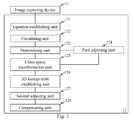
- FIG.1 is a schematic diagram illustrating an exemplary image processing device according to the present invention.
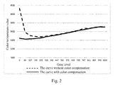
- FIG.2 is an exemplary diagram illustrating color temperature curve comparison between one example processed with color space transformation equation and another one without color temperature compensation according to the present invention.
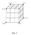
- FIG.3 is a schematic diagram illustrating a 3D LUT (LookUp Table, LUT) of one embodiment according to the present invention.
- an image processing device 12 includes an equation establishing unit 121, a calculating unit 122, a determining unit 123, a first adjusting unit 124, a color space transformation unit 125, a 3D LUT establishing unit 126, a second adjusting unit 127, and a compensating unit 128.
- An image capturing device 11 captures image signal from a displaying screen, and one input terminal of the equation establishing unit 121 receives the image signal including multiple pixels, and each of pixels has chromaticity coordinates and brightness.
- the equation establishing unit 121 may establish a color space transformation equation according to the chromaticity coordinates and brightness of pixels.
- the color space transformation equation includes conversion equations of X, Y and Z chromaticity coordinates as following equations (1):
- X n , Y n and Z n are respectively the reference values
- Each of the fixed compensation values C x , C y and C z is the same for each gray level of the image signal. Take an example of 10 bit to drive, the fixed compensation value C x is the same for 0 to 1023 gray levels, as well as the fixed compensation values C y and C z . Furthermore, the equation establishing unit 121 establishes the color space transformation equation by using a linear regression method.
- the equation establishing unit 121 outputs the color space transformation equation to the calculating unit 122, and one input terminal of the calculating unit 122 may receive the color space transformation equation from the equation establishing unit 121.
- the calculating unit 122 divides the total number of gray levels of the image signal into "i" number of first sampling points. For example, provided that the fixed number of gray levels as the interval is 64, when using 10 bit to drive is to acquire total 1024 gray levels, the total 1024 gray levels are divided into 17 first sampling points where item "i" is a positive number of 1-17 in this case.
- the number of gray levels includes 0 to 63 th levels for the item "i" of 1 ⁇ 2; the number of gray levels includes 64 th to 127 th levels for the item "i" of 2 ⁇ 3; and the like; the number of gray levels includes 960 th to 1023 th levels for the item "i" of 16 ⁇ 17.
- the item "i" is substituted into the equation (1) to obtain the reference values of X, Y and Z chromaticity coordinates for each of the first sampling points, and the reference values of X, Y and Z chromaticity coordinates would be transformed into color temperature values.
- the color temperature of dark gray level is much greater than that of the bright gray level without adding the fixed compensation values C x , C y and C z so as to result in distinct color temperature differences between the dark levels and the bright levels, and such distinct color temperature differences shown on a display screen would be seen by human eyes.
- both the dark gray levels and the bright gray levels are compensated with same compensation value to greatly reduce the color temperature values of the dark gray levels, and such compensation process decreases the color temperature differences between the dark gray levels and the bright gray levels and makes a solid-line color temperature curve of total gray levels more smooth shown on FIG.2 . Consequently, the display screen with smooth changes of the color temperature of total gray levels to be seen by human eyes is more nature, color excursion can be prevented, and display performance can be enhanced.
- the reference values of the first sampling points may be acquired by utilizing the established color space transformation equation.
- the calculating unit 122 outputs the reference values of the first sampling points to the determining unit 123.
- the determining unit 123 receives these reference values of the first sampling points with one input terminal and then determines whether these reference values of the first sampling points are within an error range or not. Provided that any one of the reference values of the first sampling point is out of the error range, the determining unit 123 outputs the reference value of the first sampling point to the first adjusting unit 124 for adjustment. After adjusting the reference value of the first sampling point, the first adjusting unit 124 outputs the adjusted reference value of the first sampling point to the color space transformation unit 125.
- the first adjusting unit 124 will adjust the reference value of the first sampling point to make ⁇ E be equal to or less than 2.0. If the difference ⁇ E between one of the reference values of the first sampling points and the default value is determined by the determining unit 123 to be within the error range, the determined reference value of the first sampling point would be directly outputted to the color space transformation unit 125.
- the determining unit 123 may be a light sensor.
- the color space transformation unit 125 receives the reference values of the first sampling points with one input terminal and transforms them into multitude reference values of second sampling points that are described with red (R), green (G) and blue (B) chromaticity coordinates.
- the second sampling points are then outputted to the 3D LUT establishing unit 126.
- the 3D LUT establishing unit 126 will establish a 3D lookup table (LUT) according to the second sampling points. Shown in FIG.3 , the red (R), green (G) and blue (B) chromaticity coordinates are divided to acquire four nodes, respectively, and the total nodes of the 3D lookup table is 64 (4 3 equals to 64). Next, the 3D lookup table is outputted to the second adjusting unit 127, and the second adjusting unit 127 would adjust the 3D lookup table for user's request and then outputs the adjusted 3D lookup table to the compensating unit 128.
- the red (R), green (G) and blue (B) chromaticity coordinates are divided to acquire four nodes, respectively, and the total nodes of the 3D lookup table is 64 (4 3 equals to 64).
- the 3D lookup table is outputted to the second adjusting unit 127, and the second adjusting unit 127 would adjust the 3D lookup table for user's request and then outputs the adjusted 3D lookup table
- the compensating unit 128 may acquire a compensation value of image parameter for each pixel by using the 3D lookup table and optimize the images to be shown on the display screen.
- the image parameter may be, but not limited to, brightness, gamma, uniformity, color temperature or other image parameters.
- the image processing device with image compensation function and its method herein provides the establishment of the 3D lookup table and the adjustment of the 3D lookup table for user's request, as well as the adjustment of the image parameters for the each pixel according to the adjusted 3D lookup table. Such a device and its method can reduce time of adjusting the image parameters.
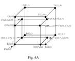
- FIG.4A is a schematic diagram illustrating the 3D LUT of one embodiment after brightness adjustment according to the present invention.
- the 3D lookup table in FIG.3 is as a basis and adjusted once more. It is noted the red (R), green (G) and blue (B) chromaticity coordinates of the 3D lookup table are reduced in equal scale in this embodiment. For example, from the original 3D lookup table, the coordinates of eight second sampling points at ends are: C(0,1,1), W(1,1,1), M(1,0,1), R(1,0,0), K(0,0,0), G(0,1,0), Y(1,1,0) and B(0,0,1).
- the original 3D lookup table is reduced in 75% scale to acquire the adjusted eight second sampling points: C'(0,0.75,0.75),W'(0.75,0.75,0.75), M'(0.75,0,0.75), R'(0.75,0,0), K'(0,0,0), G'(0,0.75,0), Y'(0.75,0.75,0) and B'(0,0,0.75) and then the adjusted 3D lookup table is acquired.
- each compensation value in respect of the brightness of each original pixel shown on the display screen can be acquired by using the scaled-down 3D lookup table. Both the whole brightness and the uniformity of the display screen would be adjusted by compensating the original pixels with the compensation values from the scaled-down 3D lookup table.
- FIG.4B is a schematic diagram illustrating the 3D LUT of one embodiment with reduction on color saturation according to the present invention.
- R, G, and B are transformed into L*, a*, and b* as follow:
- X Y Z 0.412453 0.357580 0.180423 0.212671 0.715160 0.072169 0.019334 0.119193 0.950227
- the coordinates of eight second sampling points at ends are: C(0,1,1), W(1,1,1), M(1,0,1), R(1,0,0), K(0,0,0), G(0,1,0), Y(1,1,0) and B(0,0,1).
- the red (R), green (G) and blue (B) chromaticity coordinates of the eight second sampling points are transformed into L*, a*, and b* by the equations (2), (3), (4) and (5).
- the coordinates of the transformed eight second sampling points are C'(0.376, 0.898, 0.890), W'(1.0, 1.0, 1.0), M'(0.604, 0.161, 0.576), R'(0.584, 0.118, 0.063), K'(0.0 ,0.0 ,0.0), G'(0.349, 0.871, 0.225), Y'(1.0, 0.961, 0.322) and B'(0.091, 0.039, 0.365), respectively, and the adjustment of the 3D lookup table is achieved.
- each compensation value in respect of the chromaticity of each original pixel shown on the display screen can be acquired by using the color-saturation-reduced 3D lookup table.
- the whole color saturation of the display screen would be adjusted by compensating the original pixels with the compensation values from the color-saturation-reduced 3D lookup table.
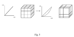
- FIG.5 is a schematic diagram illustrating a Gamma curve of one embodiment according to the present invention.
- the whole 3D lookup table is a cubic of 1024*1024*1024, and item "m" is equal to 1023.
- Coordinates R', G' and B' from the 3D lookup table are inputted in sequence into the aforementioned equations to acquire the coordinates of one pixel corresponding to the original 3D lookup table.
- the coordinates of the one pixel corresponding to the original 3D lookup table are applied onto a new 3D lookup table to obtain an adjusted gamma curve.
- the left part of FIG.5 represents the original gamma curve and the original 3D lookup table
- the right part of FIG.5 represents the adjusted gamma curve and the adjusted 3D lookup table that is compared with the original 3D lookup table.
- the original gamma curve is an inclined straight line
- the adjusted gamma curve is a quadratic curve.
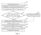
- FIG.6 is a schematic diagram illustrating a flow chart of an exemplary image process according to the present invention, and the flow chart includes steps as follows.
- Step S1 the image capturing device 11 captures the image signal of the display screen to be adjusted.
- the image signal includes a plurality of pixels, and each of that has chromaticity coordinates and brightness. Next, go to Step S2.
- Step S2 the equation establishing unit 121 establishes a color space transformation equation in respect of the pixels.
- the color space transformation equation includes transformation equations of X, Y and Z chromaticity coordinates.
- Each of the transformation equations of X, Y and Z chromaticity coordinates includes a fixed compensation value that is the same for each gray level of the image signal.
- Step S3 by using a fixed number of gray levels as an interval, the total number of gray levels of the image signal are divided into "i" number of first sampling points, and reference values of the first sampling points are acquired by calculating with the color space transformation equation. Next, go to Step S4.
- Step S4 the determining unit 123 determines whether these reference values of the first sampling points are within an error range or not. Provided that the determining unit 123 determines any one of the reference values of the first sampling point out of the error range, go to Step S5 to adjust the reference value of the first sampling point by the first adjusting unit 124. After adjusting the reference value of the first sampling point, go to Step S6. On the other hand, provided that the determining unit 123 determines any one of the reference values of the first sampling point within the error range, go to Step S6.
- Step S6 the color space transformation unit 125 transforms each of the reference values of the first sampling points into the reference values of the second sampling points that are described with the red (R), green (G) and blue (B) coordinates.
- Step S7 the 3D LUT establishing unit 126 establishes a 3D lookup table according to the reference values of these second sampling points, and then go to Step S8.
- Step S8 the second adjusting unit 127 adjusts the 3D lookup table for user's request, and then go to Step S9.
- Step S9 the compensating unit 128 generates compensation values of image parameters for the each pixel according to the adjusted 3D lookup table.
- the image processing device with image compensation and the method thereof of the present invention may further provide the display screen with equipping brightness sensor or temperature sensor to capture the image signal by the image capturing device, determine whether great differences exist between the image parameters of the image signal and the one of the adjusted image signal or not, and re-establish 3D lookup table by executing the process mentioned in the embodiments for adjustment of the image parameters if the great differences exist.
Landscapes
- Engineering & Computer Science (AREA)
- Multimedia (AREA)
- Signal Processing (AREA)
- General Physics & Mathematics (AREA)
- Theoretical Computer Science (AREA)
- Physics & Mathematics (AREA)
- Computer Hardware Design (AREA)
- Facsimile Image Signal Circuits (AREA)
- Color Image Communication Systems (AREA)
- Processing Of Color Television Signals (AREA)
- Image Processing (AREA)
- Chemical & Material Sciences (AREA)
- Crystallography & Structural Chemistry (AREA)
Applications Claiming Priority (1)
| Application Number | Priority Date | Filing Date | Title |
|---|---|---|---|
| TW104114547A TWI553622B (zh) | 2015-05-07 | 2015-05-07 | 具有影像補償功能之影像處理裝置及其影像處理方法 |
Publications (1)
| Publication Number | Publication Date |
|---|---|
| EP3131084A1 true EP3131084A1 (de) | 2017-02-15 |
Family
ID=54843680
Family Applications (1)
| Application Number | Title | Priority Date | Filing Date |
|---|---|---|---|
| EP15198127.1A Withdrawn EP3131084A1 (de) | 2015-05-07 | 2015-12-04 | Bildverarbeitungsvorrichtung mit bildkompensationsfunktion und bildverarbeitungsverfahren dafür |
Country Status (4)
| Country | Link |
|---|---|
| US (1) | US9743073B2 (de) |
| EP (1) | EP3131084A1 (de) |
| CN (1) | CN106128373B (de) |
| TW (1) | TWI553622B (de) |
Families Citing this family (18)
| Publication number | Priority date | Publication date | Assignee | Title |
|---|---|---|---|---|
| US10262605B2 (en) * | 2017-09-08 | 2019-04-16 | Apple Inc. | Electronic display color accuracy compensation |
| KR102531616B1 (ko) * | 2018-07-31 | 2023-05-12 | 삼성디스플레이 주식회사 | 색 보상 장치, 이를 갖는 전자 장치 및 전자 장치의 색 보상 방법 |
| CN110827734A (zh) * | 2018-08-07 | 2020-02-21 | 钰纬科技开发股份有限公司 | 显示器的自动Gamma曲线设置方法 |
| TWI676164B (zh) * | 2018-08-31 | 2019-11-01 | 友達光電股份有限公司 | 色度調整系統、方法以及顯示面板驅動器 |
| CN109286802A (zh) | 2018-10-22 | 2019-01-29 | 深圳Tcl新技术有限公司 | 色域匹配方法、装置、显示终端及可读存储介质 |
| CN109584768B (zh) * | 2018-11-30 | 2020-09-01 | 深圳市华星光电半导体显示技术有限公司 | 影像色温的获取方法 |
| CN109859702A (zh) * | 2018-12-28 | 2019-06-07 | 南京奥视威电子科技股份有限公司 | 一种3d查找表生成方法、显示器校色方法、显示器校色系统 |
| CN109729333B (zh) | 2018-12-28 | 2021-02-05 | 深圳Tcl新技术有限公司 | 色彩空间映射方法、装置、计算机可读存储介质及系统 |
| TWI696992B (zh) * | 2019-03-25 | 2020-06-21 | 和碩聯合科技股份有限公司 | 面板均勻性校正方法 |
| TWI687899B (zh) * | 2019-06-27 | 2020-03-11 | 鈺緯科技開發股份有限公司 | 應用於內視鏡的顯示校正系統及其校正方法 |
| US11327713B2 (en) * | 2019-10-01 | 2022-05-10 | SambaNova Systems, Inc. | Computation units for functions based on lookup tables |
| CN113744689B (zh) * | 2020-05-29 | 2022-11-22 | 北京小米移动软件有限公司 | 显示屏色域校准方法、装置和电子设备 |
| US11495177B2 (en) * | 2020-07-12 | 2022-11-08 | Novatek Microelectronics Corp. | Image processing circuit and method for compensating for IR drop on display panel |
| CN111916017A (zh) * | 2020-08-18 | 2020-11-10 | 紫旸升光电科技(苏州)有限公司 | 双显示屏色彩校正方法及校正系统 |
| CN113613007B (zh) * | 2021-07-19 | 2024-03-05 | 青岛信芯微电子科技股份有限公司 | 一种三维色彩查找表的生成方法及显示设备 |
| CN115914600A (zh) * | 2021-09-30 | 2023-04-04 | 京东方科技集团股份有限公司 | 一种色彩校正方法、系统、显示设备及芯片 |
| CN119948550A (zh) * | 2023-05-01 | 2025-05-06 | 昆山云英谷电子科技有限公司 | 用于校准显示面板的系统和方法 |
| CN120976074A (zh) * | 2025-10-20 | 2025-11-18 | 昇显微电子(苏州)股份有限公司 | 一种基于三维查找表迭代的显示面板Demura补偿方法及系统 |
Citations (4)
| Publication number | Priority date | Publication date | Assignee | Title |
|---|---|---|---|---|
| US20070211298A1 (en) * | 2006-03-08 | 2007-09-13 | Masatoshi Ishii | Image processing method and apparatus |
| US20130286040A1 (en) * | 2012-04-27 | 2013-10-31 | Renesas Electronics Corporation | Semiconductor device, image processing system, and program |
| US20140176743A1 (en) * | 2012-12-20 | 2014-06-26 | Thomson Licensing | Method, apparatus and system for publishing creative looks as three-dimensional lookup tables |
| US20150086111A1 (en) * | 2012-05-30 | 2015-03-26 | Fujifilm Corporation | Image processing method, image processing apparatus, and image processing program |
Family Cites Families (11)
| Publication number | Priority date | Publication date | Assignee | Title |
|---|---|---|---|---|
| US6177946B1 (en) * | 1997-11-14 | 2001-01-23 | Ati Technologies, Inc. | Method and apparatus for processing video data and graphics data by a graphic controller |
| US6671067B1 (en) * | 2000-01-05 | 2003-12-30 | Monaco Systems, Inc. | Scanner and printer profiling system |
| TWI222331B (en) * | 2003-08-08 | 2004-10-11 | Delta Electronics Inc | Method to display the chromatic aberration component of video signal and display device to support the chromatic aberration components with plural timings sequences |
| CN100397477C (zh) * | 2005-01-17 | 2008-06-25 | 胜华科技股份有限公司 | 一种提高显示面板亮度与影像品质的影像处理装置与方法 |
| TW200701176A (en) * | 2005-06-28 | 2007-01-01 | Etron Technology Inc | Video signal displaying system |
| JP4791233B2 (ja) * | 2006-04-10 | 2011-10-12 | 三菱電機株式会社 | 画像処理装置、画像処理方法、画像出力装置、画像処理システム |
| US20070247647A1 (en) * | 2006-04-21 | 2007-10-25 | Daniel Pettigrew | 3D lut techniques for color correcting images |
| CN101562753B (zh) * | 2008-04-18 | 2011-06-08 | 中华映管股份有限公司 | 影像处理电路和方法 |
| CN101996612A (zh) * | 2009-08-12 | 2011-03-30 | 联咏科技股份有限公司 | 增进显示装置的亮度均匀性的校正方法及相关装置 |
| US20110075043A1 (en) * | 2009-09-28 | 2011-03-31 | Au Optronics | Color shift solution for dynamic contrast ratio in a liquid crystal display |
| KR101282957B1 (ko) * | 2010-10-29 | 2013-07-08 | 엘지디스플레이 주식회사 | 입체 디스플레이의 광학 측정 장치 및 방법 |
-
2015
- 2015-05-07 TW TW104114547A patent/TWI553622B/zh active
- 2015-09-07 CN CN201510563244.5A patent/CN106128373B/zh active Active
- 2015-11-18 US US14/944,963 patent/US9743073B2/en active Active
- 2015-12-04 EP EP15198127.1A patent/EP3131084A1/de not_active Withdrawn
Patent Citations (4)
| Publication number | Priority date | Publication date | Assignee | Title |
|---|---|---|---|---|
| US20070211298A1 (en) * | 2006-03-08 | 2007-09-13 | Masatoshi Ishii | Image processing method and apparatus |
| US20130286040A1 (en) * | 2012-04-27 | 2013-10-31 | Renesas Electronics Corporation | Semiconductor device, image processing system, and program |
| US20150086111A1 (en) * | 2012-05-30 | 2015-03-26 | Fujifilm Corporation | Image processing method, image processing apparatus, and image processing program |
| US20140176743A1 (en) * | 2012-12-20 | 2014-06-26 | Thomson Licensing | Method, apparatus and system for publishing creative looks as three-dimensional lookup tables |
Also Published As
| Publication number | Publication date |
|---|---|
| TWI553622B (zh) | 2016-10-11 |
| US20160329027A1 (en) | 2016-11-10 |
| CN106128373A (zh) | 2016-11-16 |
| US9743073B2 (en) | 2017-08-22 |
| TW201640482A (zh) | 2016-11-16 |
| CN106128373B (zh) | 2018-07-10 |
Similar Documents
| Publication | Publication Date | Title |
|---|---|---|
| US9743073B2 (en) | Image processing device with image compensation function and image processing method thereof | |
| US10839731B2 (en) | Mura correction system | |
| US8890884B2 (en) | Image processing device converting a color represented by inputted data into a color within a color reproduction range of a predetermined output device and image processing method thereof | |
| CN101690161B (zh) | 用于自动地计算伽马校正曲线的设备和方法 | |
| JP4566953B2 (ja) | 液晶表示装置の駆動装置及び駆動方法 | |
| US8411936B2 (en) | Apparatus and method for color reproduction | |
| US8237753B2 (en) | Display device with gradation conversion, and method thereof | |
| US8189941B2 (en) | Image processing device, display device, image processing method, and program | |
| US8111301B2 (en) | Method of performing auto white balance in YCbCr color space | |
| US6297801B1 (en) | Edge-adaptive chroma up-conversion | |
| JP2010199659A (ja) | 画像処理装置、及び画像処理方法 | |
| EP3136379B1 (de) | Bildverarbeitungsvorrichtung und anzeigebestimmungsverfahren | |
| JP5002348B2 (ja) | 画像処理装置、映像受信装置および画像処理方法 | |
| US20150235618A1 (en) | Image processing apparatus capable of inputting image data | |
| US7443453B2 (en) | Dynamic image saturation enhancement apparatus | |
| US8284316B2 (en) | Real-time image processing circuit capable of enhancing brightness contrast and color saturation | |
| US8269804B2 (en) | Image display apparatus and method for correcting color signals based on a sub-pixel location and a position of a viewer | |
| US20140327695A1 (en) | Image processing apparatus and control method therefor | |
| US20100245226A1 (en) | Image signal processing device | |
| KR20120054458A (ko) | 색역 확장 방법 및 유닛과, 그를 이용한 광색역 표시 장치 | |
| KR101441380B1 (ko) | 선호색 검출 방법 및 장치와, 그를 이용한 액정 표시 장치 | |
| Thomas et al. | Additivity based LC display color characterization | |
| CN100539634C (zh) | 一种画面显示装置及其显示方法 | |
| JP6537401B2 (ja) | 映像信号の画面輝度を調整する表示装置及び調整回路 | |
| US20230147884A1 (en) | Display data processing device, image display system, and display data processing method |
Legal Events
| Date | Code | Title | Description |
|---|---|---|---|
| PUAI | Public reference made under article 153(3) epc to a published international application that has entered the european phase |
Free format text: ORIGINAL CODE: 0009012 |
|
| 17P | Request for examination filed |
Effective date: 20160606 |
|
| AK | Designated contracting states |
Kind code of ref document: A1 Designated state(s): AL AT BE BG CH CY CZ DE DK EE ES FI FR GB GR HR HU IE IS IT LI LT LU LV MC MK MT NL NO PL PT RO RS SE SI SK SM TR |
|
| AX | Request for extension of the european patent |
Extension state: BA ME |
|
| RBV | Designated contracting states (corrected) |
Designated state(s): AL AT BE BG CH CY CZ DE DK EE ES FI FR GB GR HR HU IE IS IT LI LT LU LV MC MK MT NL NO PL PT RO RS SE SI SK SM TR |
|
| 17Q | First examination report despatched |
Effective date: 20190313 |
|
| STAA | Information on the status of an ep patent application or granted ep patent |
Free format text: STATUS: THE APPLICATION IS DEEMED TO BE WITHDRAWN |
|
| 18D | Application deemed to be withdrawn |
Effective date: 20190524 |