EP3130782A2 - Turbomachine fluid valve comprising a cooled solenoid - Google Patents
Turbomachine fluid valve comprising a cooled solenoid Download PDFInfo
- Publication number
- EP3130782A2 EP3130782A2 EP16183764.6A EP16183764A EP3130782A2 EP 3130782 A2 EP3130782 A2 EP 3130782A2 EP 16183764 A EP16183764 A EP 16183764A EP 3130782 A2 EP3130782 A2 EP 3130782A2
- Authority
- EP
- European Patent Office
- Prior art keywords
- valve
- fluid
- solenoid
- casing
- orientation
- Prior art date
- Legal status (The legal status is an assumption and is not a legal conclusion. Google has not performed a legal analysis and makes no representation as to the accuracy of the status listed.)
- Granted
Links
Images


Classifications
-
- F—MECHANICAL ENGINEERING; LIGHTING; HEATING; WEAPONS; BLASTING
- F16—ENGINEERING ELEMENTS AND UNITS; GENERAL MEASURES FOR PRODUCING AND MAINTAINING EFFECTIVE FUNCTIONING OF MACHINES OR INSTALLATIONS; THERMAL INSULATION IN GENERAL
- F16K—VALVES; TAPS; COCKS; ACTUATING-FLOATS; DEVICES FOR VENTING OR AERATING
- F16K31/00—Actuating devices; Operating means; Releasing devices
- F16K31/002—Actuating devices; Operating means; Releasing devices actuated by temperature variation
-
- F—MECHANICAL ENGINEERING; LIGHTING; HEATING; WEAPONS; BLASTING
- F02—COMBUSTION ENGINES; HOT-GAS OR COMBUSTION-PRODUCT ENGINE PLANTS
- F02C—GAS-TURBINE PLANTS; AIR INTAKES FOR JET-PROPULSION PLANTS; CONTROLLING FUEL SUPPLY IN AIR-BREATHING JET-PROPULSION PLANTS
- F02C7/00—Features, components parts, details or accessories, not provided for in, or of interest apart form groups F02C1/00 - F02C6/00; Air intakes for jet-propulsion plants
- F02C7/22—Fuel supply systems
- F02C7/232—Fuel valves; Draining valves or systems
-
- F—MECHANICAL ENGINEERING; LIGHTING; HEATING; WEAPONS; BLASTING
- F16—ENGINEERING ELEMENTS AND UNITS; GENERAL MEASURES FOR PRODUCING AND MAINTAINING EFFECTIVE FUNCTIONING OF MACHINES OR INSTALLATIONS; THERMAL INSULATION IN GENERAL
- F16K—VALVES; TAPS; COCKS; ACTUATING-FLOATS; DEVICES FOR VENTING OR AERATING
- F16K27/00—Construction of housing; Use of materials therefor
- F16K27/02—Construction of housing; Use of materials therefor of lift valves
- F16K27/029—Electromagnetically actuated valves
-
- F—MECHANICAL ENGINEERING; LIGHTING; HEATING; WEAPONS; BLASTING
- F16—ENGINEERING ELEMENTS AND UNITS; GENERAL MEASURES FOR PRODUCING AND MAINTAINING EFFECTIVE FUNCTIONING OF MACHINES OR INSTALLATIONS; THERMAL INSULATION IN GENERAL
- F16K—VALVES; TAPS; COCKS; ACTUATING-FLOATS; DEVICES FOR VENTING OR AERATING
- F16K31/00—Actuating devices; Operating means; Releasing devices
- F16K31/02—Actuating devices; Operating means; Releasing devices electric; magnetic
- F16K31/06—Actuating devices; Operating means; Releasing devices electric; magnetic using a magnet, e.g. diaphragm valves, cutting off by means of a liquid
- F16K31/0644—One-way valve
- F16K31/0655—Lift valves
- F16K31/0665—Lift valves with valve member being at least partially ball-shaped
-
- F—MECHANICAL ENGINEERING; LIGHTING; HEATING; WEAPONS; BLASTING
- F16—ENGINEERING ELEMENTS AND UNITS; GENERAL MEASURES FOR PRODUCING AND MAINTAINING EFFECTIVE FUNCTIONING OF MACHINES OR INSTALLATIONS; THERMAL INSULATION IN GENERAL
- F16K—VALVES; TAPS; COCKS; ACTUATING-FLOATS; DEVICES FOR VENTING OR AERATING
- F16K49/00—Means in or on valves for heating or cooling
- F16K49/005—Circulation means for a separate heat transfer fluid
-
- F—MECHANICAL ENGINEERING; LIGHTING; HEATING; WEAPONS; BLASTING
- F05—INDEXING SCHEMES RELATING TO ENGINES OR PUMPS IN VARIOUS SUBCLASSES OF CLASSES F01-F04
- F05D—INDEXING SCHEME FOR ASPECTS RELATING TO NON-POSITIVE-DISPLACEMENT MACHINES OR ENGINES, GAS-TURBINES OR JET-PROPULSION PLANTS
- F05D2260/00—Function
- F05D2260/20—Heat transfer, e.g. cooling
Definitions
- the present disclosure relates to valves, more specifically to fuel valves (e.g., for use with turbomachines).
- Fuel control for a gas turbine engine is traditionally accomplished by a fuel metering valve and a flow dividing function upstream of the fuel nozzles.
- Such systems have multiple manifolds supplying fuel to the fuel nozzles at differing flow rates.
- traditional turbomachine systems do not use electronic fuel valves (e.g., solenoid valves) due to the thermal conditions that the valves are exposed to and since there has yet to be a solution for thermally regulating such electronic fuel valves.
- a fluid valve use in a turbomachine in a high temperature location includes a fluid inlet, a fluid outlet, a fluid circuit defined between the fluid inlet and the fluid outlet, and a solenoid including a solenoid casing.
- the solenoid is disposed between the fluid inlet and fluid outlet.
- the solenoid is configured to move a valve member between a closed position, at least one partially open position (e.g., any number of suitable positions), and a fully open position to selectively meter fluid flow through the fluid circuit.
- the fluid valve can include a valve casing, wherein the solenoid and valve member are disposed in the valve casing.
- the fluid circuit can include at least one thermal regulation portion to thermally regulate the solenoid temperature.
- the thermal regulation portion of the fluid circuit can be defined around at least a portion of the circumference of the solenoid to thermally regulate the solenoid. In certain embodiments, the fluid circuit can be defined more than about 330 degrees around the solenoid or any other suitable amount around the solenoid.
- the thermal regulation portion of the fluid circuit can be defined by an inner wall of the valve casing and an outer wall of the solenoid casing.
- the solenoid casing can include a blocking feature protruding therefrom and contacting the inner wall of the valve casing adjacent to the fluid inlet such that the fluid flows around the solenoid before entering a valve chamber housing the valve member.
- the valve can include at least one thermal isolation pocket defined between a valve casing and an internal valve component.
- the internal valve component can be a spacer skirt.
- the at least one thermal isolation pocket can be defined downstream of the valve member.
- the valve casing can include a body portion and a cap portion configured to be connected to the body portion.
- the solenoid can include an orientation feature extending from the solenoid casing, wherein the cap portion includes an orientation aperture configured to receive the orientation feature and orient the solenoid relative to the fluid inlet such that fluid must flow around the solenoid before entering the a valve chamber.
- the cap portion can be configured to connect to the body portion in a predetermined orientation to orient the solenoid.
- the cap portion and body portion can include a plurality of corresponding flanges that are asymmetrically spaced about a circumference thereof such that the cap portion mounts to the body portion in a single orientation.
- the orientation feature can house electrical wiring for the solenoid.
- a fuel nozzle for a turbomachine can include a fluid valve as described above and a nozzle tip extending from the fluid valve downstream from the valve member, wherein the nozzle tip is configured to supply fluid to a turbomachine combustor.
- a method of assembling a fluid valve can include assembling inner valve components, inserting the inner valve components into a valve casing body portion, orienting the inner valve components relative to a fluid inlet in the valve casing body portion, and securing the inner valve components within the valve casing body with a valve casing cap portion such that the valve casing cap portion receives an orientation feature to fix the orientation of the inner valve components relative to the fluid inlet.
- FIG. 1 an illustrative view of an embodiment of a fuel nozzle in accordance with the disclosure is shown in Fig. 1 and is designated generally by reference character 100.
- FIGs. 2-6H Other embodiments and/or aspects of this disclosure are shown in Figs. 2-6H .
- the systems and methods described herein can be used to meter fluid using electrical flow metering devices while thermally regulating the electrical components of the valve.
- a fuel nozzle 100 includes a fluid valve 101 that has a fluid inlet 103 and a fluid outlet 105.
- a fluid circuit is defined between the fluid inlet 103 and the fluid outlet 105. While the fluid valve 101 is described as operating with a fuel nozzle 100, it is contemplated that fluid valve can be configured for use with any suitable fluid (e.g., coolant, air, fuel).
- Flow arrows in Fig. 2 show portions of an embodiment of a fluid circuit.
- the fluid valve 101 includes a solenoid 107 which has a solenoid casing 107a and is disposed between the fluid inlet 103 and fluid outlet 105.
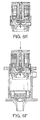
- the solenoid 107 is configured to move a valve member 109 between a closed position (e.g., as shown in Fig. 5A ), at least one partially open position (e.g., as shown in Fig. 5B ). and a fully open position (e.g., as shown in Fig. 5C ) to selectively meter fluid flow through the fluid circuit.
- the valve member 109 can be configured to be moved and held in any suitable position (e.g., discreetly defined or not) between the closed position and the fully opened position.
- valve member 109 can include a ball valve assembly having any suitable design known in the art (e.g., mounted to flexures 113 configured to provide cloture force bias). Any other suitable valve assembly for valve member 109 is contemplated herein.
- the fluid valve 101 can include a valve casing 111 that holds the internal components of the valve 101 (e.g., the solenoid 107, valve member 109, and any other suitable valve components associated therewith).
- the valve casing 111 can include a body portion 111a and a cap portion 111b that is configured to be connected to the body portion 111a in any suitable manner (e.g., via fasteners 111c as shown).
- the fluid circuit can include at least one thermal regulation portion 115 to thermally regulate the solenoid 107 temperature.
- the thermal regulation portion 115 of the fluid circuit can be defined around at least a portion of the circumference of the solenoid 107 to thermally regulate the solenoid 107.
- the thermal regulation portion 115 of the fluid circuit can be defined more than about 330 degrees around the solenoid or any other suitable amount around the solenoid (e.g., up to but not including 360 degrees, several rotations around solenoid 107 defined by one or more spiral channels in the solenoid casing 107a).
- the thermal regulation portion 115 of the fluid circuit can be defined by an inner wall of the valve casing 111 and an outer wall of the solenoid casing 107a.
- the solenoid casing 107a can include a blocking feature 117 protruding therefrom and contacting the inner wall of the valve casing 111 adjacent to the fluid inlet 103 such that the fluid flows around the solenoid 107 before entering a valve chamber 119 housing the valve member 109.
- the blocking feature 117 can block fluid that is entering the fluid circuit from the inlet 103 from traveling directly to the valve chamber 119 which will cause the fluid to travel around the solenoid 107 (e.g., to absorb heat from the solenoid 107).
- the valve 101 can include at least one thermal isolation pocket 121 defined between a valve casing 111 and a suitable internal valve component.
- the internal valve component that creates one or more isolation pockets 121 can be a spacer skirt 123.
- the at least one thermal isolation pocket 121 can be defined downstream of the valve member 109 (e.g., toward a heat source) and/or in any other suitable location.
- the solenoid 107 can include an orientation feature 107b extending from the solenoid casing 107a.
- the cap portion 111f includes an orientation aperture 125 configured to receive the orientation feature 107b and orient the solenoid 107 relative to the fluid inlet 103 such that fluid must flow around the solenoid 107 before entering the valve chamber 119.
- the orientation feature 107b can house electrical wiring for the solenoid 107.
- the cap portion 111b can be configured to connect to the body portion I I a in a predetermined orientation to orient the solenoid 107.
- the cap portion 111b and body portion 111a can include a plurality of corresponding flanges 127a, 127b that are asymmetrically spaced about a circumference thereof such that the cap portion 111b mounts to the body portion 111a in a single orientation.
- the cap portion 111b can be sealed to the solenoid 107 and/or the body portion 111a of the valve casing 111 in any suitable manner (e.g., o-rings 110). Additionally or alternatively, one or more shims 112 can be disposed between the cap portion 111b and the body portion 111c to control the compressive stress imparted to the solenoid 107 and/or other internal valve components.
- the fuel nozzle 100 can include a nozzle tip 102 extending from the fluid valve 101 downstream from the valve member 109.
- the nozzle tip 102 can have any suitable shape and can be configured to supply fuel to a turbomachine combustor.
- a method of assembling a fluid valve 101 can include assembling inner valve components, inserting the inner valve components into a valve casing body portion 111a, orienting the inner valve components relative to a fluid inlet 103 in the valve casing body portion 111a, and securing the inner valve components within the valve casing body portion 111a with a valve casing cap portion 111b such that the valve casing cap 111b portion receives an orientation feature 107b to fix the orientation of the inner valve components relative to the fluid inlet 103.
- a snap lock cup 131 can be inserted over the valve member 109 and associated components to snap lock with a flange in the solenoid casing 107a.
- the snap lock cup 131 can retain to the valve member 109 (and/or other suitable associated components) and the solenoid 107 in any suitable manner (e.g., via threaded lock nut 133 and lock ring 135).
- the inner valve components can be inserted into the valve casing body portion 103, oriented to cause the fluid to flow around the solenoid 107, and locked into place by the cap portion 111b.
- a single proportional electronic fluid metering valve can be integrated in a fuel nozzle 100 (e.g., for a turbomachine). Where heat would usually prevent the use of a solenoid so close to a combustor, the fluid valve 101 has the thermal regulation portion 115 of the fluid circuit that cools the solenoid 107 (and/or other electronics).
- the valve 101 can be configured as a removable component from the fuel nozzle 100 (e.g., for calibration, repair, and/or replacement).
Landscapes
- Engineering & Computer Science (AREA)
- General Engineering & Computer Science (AREA)
- Mechanical Engineering (AREA)
- Chemical & Material Sciences (AREA)
- Combustion & Propulsion (AREA)
- Physics & Mathematics (AREA)
- Thermal Sciences (AREA)
- Electromagnetism (AREA)
- Magnetically Actuated Valves (AREA)
- Temperature-Responsive Valves (AREA)
- Details Of Valves (AREA)
Abstract
Description
- The present disclosure relates to valves, more specifically to fuel valves (e.g., for use with turbomachines).
- Fuel control for a gas turbine engine is traditionally accomplished by a fuel metering valve and a flow dividing function upstream of the fuel nozzles. Such systems have multiple manifolds supplying fuel to the fuel nozzles at differing flow rates. However, traditional turbomachine systems do not use electronic fuel valves (e.g., solenoid valves) due to the thermal conditions that the valves are exposed to and since there has yet to be a solution for thermally regulating such electronic fuel valves.
- Such conventional methods and systems have generally been considered satisfactory for their intended purpose. However, there is still a need in the art for improved fuel valves (e.g., for turbomachines). The present disclosure provides a solution for this need.
- In accordance with at least one aspect of this disclosure, a fluid valve use in a turbomachine in a high temperature location includes a fluid inlet, a fluid outlet, a fluid circuit defined between the fluid inlet and the fluid outlet, and a solenoid including a solenoid casing. The solenoid is disposed between the fluid inlet and fluid outlet. The solenoid is configured to move a valve member between a closed position, at least one partially open position (e.g., any number of suitable positions), and a fully open position to selectively meter fluid flow through the fluid circuit. The fluid valve can include a valve casing, wherein the solenoid and valve member are disposed in the valve casing.
- The fluid circuit can include at least one thermal regulation portion to thermally regulate the solenoid temperature. The thermal regulation portion of the fluid circuit can be defined around at least a portion of the circumference of the solenoid to thermally regulate the solenoid. In certain embodiments, the fluid circuit can be defined more than about 330 degrees around the solenoid or any other suitable amount around the solenoid.
- The thermal regulation portion of the fluid circuit can be defined by an inner wall of the valve casing and an outer wall of the solenoid casing. The solenoid casing can include a blocking feature protruding therefrom and contacting the inner wall of the valve casing adjacent to the fluid inlet such that the fluid flows around the solenoid before entering a valve chamber housing the valve member.
- The valve can include at least one thermal isolation pocket defined between a valve casing and an internal valve component. The internal valve component can be a spacer skirt. The at least one thermal isolation pocket can be defined downstream of the valve member.
- The valve casing can include a body portion and a cap portion configured to be connected to the body portion. The solenoid can include an orientation feature extending from the solenoid casing, wherein the cap portion includes an orientation aperture configured to receive the orientation feature and orient the solenoid relative to the fluid inlet such that fluid must flow around the solenoid before entering the a valve chamber.
- The cap portion can be configured to connect to the body portion in a predetermined orientation to orient the solenoid. For example, in certain embodiments, the cap portion and body portion can include a plurality of corresponding flanges that are asymmetrically spaced about a circumference thereof such that the cap portion mounts to the body portion in a single orientation. In certain embodiments, the orientation feature can house electrical wiring for the solenoid.
- In accordance with at least one aspect of this disclosure, a fuel nozzle for a turbomachine can include a fluid valve as described above and a nozzle tip extending from the fluid valve downstream from the valve member, wherein the nozzle tip is configured to supply fluid to a turbomachine combustor.
- In accordance with at least one aspect of this disclosure, a method of assembling a fluid valve can include assembling inner valve components, inserting the inner valve components into a valve casing body portion, orienting the inner valve components relative to a fluid inlet in the valve casing body portion, and securing the inner valve components within the valve casing body with a valve casing cap portion such that the valve casing cap portion receives an orientation feature to fix the orientation of the inner valve components relative to the fluid inlet.
- These and other features of the systems and methods of the subject disclosure will become more readily apparent to those skilled in the art from the following detailed description taken in conjunction with the drawings.
- So that those skilled in the art to which the subject disclosure appertains will readily understand how to make and use the devices and methods of the subject disclosure without undue experimentation, embodiments thereof will be described in detail herein below with reference to certain figures, wherein:
-
Fig. 1 is a cross-sectional elevation view of an embodiment of a fuel nozzle in accordance with this disclosure; -
Fig. 2 is a perspective partial cross-sectional view of an embodiment of a fluid valve of the fuel nozzle ofFig. 1 , shown in an open position wherein the fluid flow is shown schematically wrapping around a solenoid of the fluid valve; -
Fig. 3 is a cross-sectional elevation view of a lower portion of the fluid valve ofFig. 2 , showing thermal isolation pockets defined by a spacer skirt; -
Fig. 4A is partial cross-sectional perspective view of an upper portion of the fluid valve ofFig. 2 , showing a cap portion of the valve casing having an orientation aperture and secured to a body portion of the valve casing; -
Fig. 4B is a perspective view of the upper portion of the fluid valve ofFig. 4 ; -
Fig. 4C is an exploded perspective view of the upper portion of the fluid valve ofFig 4 , showing the cap portion removed from the body portion of the valve casing:-
Figs. 5A-5C are cross-sectional elevation views of the valve member of the fluid valve shown in a closed position, a partially opened position, and a fully opened position, respectively; and -
Figs. 6A-6H illustrate an embodiment of an assembly process of a fluid valve and/or fuel nozzle in accordance with this disclosure.
-
- Reference will now be made to the drawings wherein like reference numerals identify similar structural features or aspects of the subject disclosure. For purposes of explanation and illustration, and not limitation, an illustrative view of an embodiment of a fuel nozzle in accordance with the disclosure is shown in
Fig. 1 and is designated generally byreference character 100. Other embodiments and/or aspects of this disclosure are shown inFigs. 2-6H . The systems and methods described herein can be used to meter fluid using electrical flow metering devices while thermally regulating the electrical components of the valve. - Referring to
Figs. 1 ,2 , and3 , afuel nozzle 100 includes afluid valve 101 that has afluid inlet 103 and afluid outlet 105. A fluid circuit is defined between thefluid inlet 103 and thefluid outlet 105. While thefluid valve 101 is described as operating with afuel nozzle 100, it is contemplated that fluid valve can be configured for use with any suitable fluid (e.g., coolant, air, fuel). Flow arrows inFig. 2 show portions of an embodiment of a fluid circuit. Thefluid valve 101 includes asolenoid 107 which has asolenoid casing 107a and is disposed between thefluid inlet 103 andfluid outlet 105. - The
solenoid 107 is configured to move avalve member 109 between a closed position (e.g., as shown inFig. 5A ), at least one partially open position (e.g., as shown inFig. 5B ). and a fully open position (e.g., as shown inFig. 5C ) to selectively meter fluid flow through the fluid circuit. For example, thevalve member 109 can be configured to be moved and held in any suitable position (e.g., discreetly defined or not) between the closed position and the fully opened position. - As shown, the
valve member 109 can include a ball valve assembly having any suitable design known in the art (e.g., mounted toflexures 113 configured to provide cloture force bias). Any other suitable valve assembly forvalve member 109 is contemplated herein. - The
fluid valve 101 can include avalve casing 111 that holds the internal components of the valve 101 (e.g., thesolenoid 107,valve member 109, and any other suitable valve components associated therewith). Thevalve casing 111 can include abody portion 111a and acap portion 111b that is configured to be connected to thebody portion 111a in any suitable manner (e.g., viafasteners 111c as shown). - The fluid circuit can include at least one
thermal regulation portion 115 to thermally regulate thesolenoid 107 temperature. Thethermal regulation portion 115 of the fluid circuit can be defined around at least a portion of the circumference of thesolenoid 107 to thermally regulate thesolenoid 107. In certain embodiments, thethermal regulation portion 115 of the fluid circuit can be defined more than about 330 degrees around the solenoid or any other suitable amount around the solenoid (e.g., up to but not including 360 degrees, several rotations aroundsolenoid 107 defined by one or more spiral channels in thesolenoid casing 107a). - The
thermal regulation portion 115 of the fluid circuit can be defined by an inner wall of thevalve casing 111 and an outer wall of thesolenoid casing 107a. As shown, thesolenoid casing 107a can include ablocking feature 117 protruding therefrom and contacting the inner wall of thevalve casing 111 adjacent to thefluid inlet 103 such that the fluid flows around thesolenoid 107 before entering avalve chamber 119 housing thevalve member 109. Restated, the blockingfeature 117 can block fluid that is entering the fluid circuit from theinlet 103 from traveling directly to thevalve chamber 119 which will cause the fluid to travel around the solenoid 107 (e.g., to absorb heat from the solenoid 107). - Alternatively and/or in addition to the
thermal regulation portion 115 of the fluid circuit, thevalve 101 can include at least onethermal isolation pocket 121 defined between avalve casing 111 and a suitable internal valve component. As shown, the internal valve component that creates one or more isolation pockets 121 can be aspacer skirt 123. The at least onethermal isolation pocket 121 can be defined downstream of the valve member 109 (e.g., toward a heat source) and/or in any other suitable location. - Referring additionally to
Figs. 4A-4C , thesolenoid 107 can include anorientation feature 107b extending from thesolenoid casing 107a. The cap portion 111f includes anorientation aperture 125 configured to receive theorientation feature 107b and orient thesolenoid 107 relative to thefluid inlet 103 such that fluid must flow around thesolenoid 107 before entering thevalve chamber 119. In certain embodiments, theorientation feature 107b can house electrical wiring for thesolenoid 107. - The
cap portion 111b can be configured to connect to the body portion I I a in a predetermined orientation to orient thesolenoid 107. For example, in certain embodiments, thecap portion 111b andbody portion 111a can include a plurality ofcorresponding flanges cap portion 111b mounts to thebody portion 111a in a single orientation. - The
cap portion 111b can be sealed to thesolenoid 107 and/or thebody portion 111a of thevalve casing 111 in any suitable manner (e.g., o-rings 110). Additionally or alternatively, one ormore shims 112 can be disposed between thecap portion 111b and thebody portion 111c to control the compressive stress imparted to thesolenoid 107 and/or other internal valve components. - The
fuel nozzle 100 can include anozzle tip 102 extending from thefluid valve 101 downstream from thevalve member 109. Thenozzle tip 102 can have any suitable shape and can be configured to supply fuel to a turbomachine combustor. - In accordance with at least one aspect of this disclosure, referring additionally to
Figs. 6A-6H a method of assembling afluid valve 101 can include assembling inner valve components, inserting the inner valve components into a valvecasing body portion 111a, orienting the inner valve components relative to afluid inlet 103 in the valvecasing body portion 111a, and securing the inner valve components within the valvecasing body portion 111a with a valvecasing cap portion 111b such that thevalve casing cap 111b portion receives anorientation feature 107b to fix the orientation of the inner valve components relative to thefluid inlet 103. - As shown in
Figs. 6A-6C , asnap lock cup 131 can be inserted over thevalve member 109 and associated components to snap lock with a flange in thesolenoid casing 107a. Referring toFigs. 6C and6D , thesnap lock cup 131 can retain to the valve member 109 (and/or other suitable associated components) and thesolenoid 107 in any suitable manner (e.g., via threadedlock nut 133 and lock ring 135). - Referring to
Fig. 6E-6H , after assembly of the inner valve components as described above, the inner valve components can be inserted into the valvecasing body portion 103, oriented to cause the fluid to flow around thesolenoid 107, and locked into place by thecap portion 111b. - Utilizing the above, a single proportional electronic fluid metering valve can be integrated in a fuel nozzle 100 (e.g., for a turbomachine). Where heat would usually prevent the use of a solenoid so close to a combustor, the
fluid valve 101 has thethermal regulation portion 115 of the fluid circuit that cools the solenoid 107 (and/or other electronics). Thevalve 101 can be configured as a removable component from the fuel nozzle 100 (e.g., for calibration, repair, and/or replacement). - The methods and systems of the present disclosure, as described above and shown in the drawings, provide for fuel nozzles and valves with superior properties including thermal regulation. While the apparatus and methods of the subject disclosure have been shown and described with reference to embodiments, those skilled in the art will readily appreciate that changes and/or modifications may be made thereto without departing from the spirit and scope of the subject disclosure.
Claims (15)
- A fluid valve (101) for use in a turbomachine in a high temperature location, comprising:a fluid inlet (103);a fluid outlet (105);a fluid circuit defined between the fluid inlet (103) and the fluid outlet (105); anda solenoid (107) including a solenoid casing (107a) and disposed between the fluid inlet (103) and fluid outlet (105), the solenoid (107) configured to move a valve member (109) between a closed position, at least one partially open position, and a fully open position to selectively meter fluid flow through the fluid circuit.
- The fluid valve of claim 1, further including a valve casing (111), wherein the solenoid (107) and valve member (109) are disposed in the valve casing (111).
- The fluid valve of claim 2, wherein a thermal regulation portion (115) of the fluid circuit is defined around at least a portion of the circumference of the solenoid (107) to thermally regulate the solenoid (107).
- The fluid valve of claim 3, wherein the fluid circuit is defined more than about 330 degrees around the solenoid (107).
- The fluid valve of claim 3, wherein the thermal regulation portion (115) of the fluid circuit is defined by an inner wall of the valve casing (111) and an outer wall of the solenoid casing (107).
- The fluid valve of claim 5, wherein the solenoid casing (107a) includes a blocking feature protruding therefrom and contacting the inner wall of the valve casing (111) adjacent to the fluid inlet (103) such that the fluid flows around the solenoid (107) before entering a valve chamber housing the valve member (109).
- The fluid valve of any preceding claim, further comprising at least one thermal isolation pocket (121) defined between a valve casing (111) and an internal valve component.
- The fluid valve of claim 7, wherein the internal valve component is a spacer skirt, and preferably wherein the at least one thermal isolation pocket (121) is defined downstream of the valve member (109).
- The fluid valve of claim 2, wherein the valve casing (111) includes a body portion (111a) and a cap (111b) portion configured to be connected to the body portion (111a).
- The fluid valve of claim 9, wherein the solenoid (107) includes an orientation features (107b) extending from the solenoid casing (107a), wherein the cap portion (111b) includes an orientation aperture (125) configured to receive the orientation feature (107b) and orient the solenoid (107) relative to the fluid inlet (103) such that fluid must flow around the solenoid (107) before entering the a valve chamber.
- The fluid valve of claim 10, wherein the cap portion (111b) is configured to connect to the body portion (111a) in a predetermined orientation to orient the solenoid (107).
- The fluid valve of claim 11, wherein the cap portion (111b) and body portion (111a) include a plurality of corresponding flanges that are asymmetrically spaced about a circumference thereof such that the cap portion (111 b) mounts to the body portion (111a) in a single orientation.
- The fluid valve of claim 10, wherein the orientation feature (107a) houses electrical wiring for the solenoid (107).
- A fuel nozzle (100) for a turbomachine, comprising: the fluid valve (101) of any preceding claim, and further comprising;
a nozzle tip extending from the fluid valve downstream from the valve member, wherein the nozzle tip is configured to supply fluid to a turbomachine combustor - A method of assembling a fluid valve (101), comprising:assembling inner valve components;inserting the inner valve components into a valve casing body portion (111a):orienting the inner valve components relative to a fluid inlet (103) in the valve casing body portion (111a); andsecuring the inner valve components within the valve casing body (111a) with a valve casing cap portion (111b) such that the valve casing cap portion (111b) receives an orientation feature (107b) to fix the orientation of the inner valve components relative to the fluid inlet (103).
Applications Claiming Priority (1)
| Application Number | Priority Date | Filing Date | Title |
|---|---|---|---|
| US14/825,474 US10487957B2 (en) | 2015-08-13 | 2015-08-13 | Fluid valves |
Publications (3)
| Publication Number | Publication Date |
|---|---|
| EP3130782A2 true EP3130782A2 (en) | 2017-02-15 |
| EP3130782A3 EP3130782A3 (en) | 2017-05-10 |
| EP3130782B1 EP3130782B1 (en) | 2020-09-30 |
Family
ID=56851384
Family Applications (1)
| Application Number | Title | Priority Date | Filing Date |
|---|---|---|---|
| EP16183764.6A Active EP3130782B1 (en) | 2015-08-13 | 2016-08-11 | Turbomachine fluid valve comprising a cooled solenoid |
Country Status (2)
| Country | Link |
|---|---|
| US (2) | US10487957B2 (en) |
| EP (1) | EP3130782B1 (en) |
Cited By (2)
| Publication number | Priority date | Publication date | Assignee | Title |
|---|---|---|---|---|
| EP3460334A1 (en) * | 2017-09-25 | 2019-03-27 | Delavan, Inc. | Electronic fuel control for gas turbine engines |
| FR3103522A1 (en) * | 2019-11-25 | 2021-05-28 | Safran Aircraft Engines | FUEL INJECTION DEVICE |
Families Citing this family (12)
| Publication number | Priority date | Publication date | Assignee | Title |
|---|---|---|---|---|
| JP6378980B2 (en) * | 2014-09-04 | 2018-08-22 | Kyb株式会社 | Solenoid valve |
| DE102017222638A1 (en) * | 2017-12-13 | 2019-06-13 | Robert Bosch Gmbh | Solenoid valve and method for producing a solenoid valve |
| US11913381B1 (en) | 2022-08-26 | 2024-02-27 | Hamilton Sundstrand Corporation | Force modification of passive spool for control of secondary nozzle circuits |
| US12313004B2 (en) | 2022-08-26 | 2025-05-27 | Collins Engine Nozzles, Inc. | Proportional force modification of passive spool for control of secondary nozzle circuits |
| US12270343B2 (en) | 2022-08-26 | 2025-04-08 | Collins Engine Nozzles, Inc. | Proportional restriction of fuel nozzle with an auxiliary circuit |
| US11970977B2 (en) | 2022-08-26 | 2024-04-30 | Hamilton Sundstrand Corporation | Variable restriction of a secondary circuit of a fuel injector |
| US12305581B2 (en) | 2022-08-26 | 2025-05-20 | Collins Engine Nozzles, Inc. | Proportional restriction of a secondary circuit of a fuel injector |
| US20240068412A1 (en) * | 2022-08-26 | 2024-02-29 | Hamilton Sundstrand Corporation | Force modification of passive spool for control of simplex circuit of fuel nozzles |
| US12286931B2 (en) | 2022-08-26 | 2025-04-29 | Collins Engine Nozzles, Inc. | Variable restriction of a fuel circuit of a fuel nozzle |
| US12454915B2 (en) | 2022-08-26 | 2025-10-28 | Hamilton Sundstrand Corporation | Force modification of passive valve spools for control of nozzles |
| US11970976B2 (en) | 2022-08-26 | 2024-04-30 | Hamilton Sundstrand Corporation | Variable restriction of fuel nozzle with an auxiliary circuit |
| US11913382B1 (en) | 2022-08-26 | 2024-02-27 | Hamilton Sundstrand Corporation | Variable restriction of a fuel circuit of a fuel nozzle |
Family Cites Families (27)
| Publication number | Priority date | Publication date | Assignee | Title |
|---|---|---|---|---|
| US1239537A (en) * | 1916-06-14 | 1917-09-11 | Jesse J Shuman | Mixing-machine. |
| DE1239537B (en) | 1961-12-20 | 1967-04-27 | Parker Hannifin Corp | Electromagnetically operated valve with an armature which plunges into a solenoid and forms the locking piece |
| US3695037A (en) | 1970-09-08 | 1972-10-03 | Teledyne Ind | Shaft mounted fuel control |
| US4180022A (en) * | 1977-10-31 | 1979-12-25 | Chrysler Corporation | Fuel injection system and control valve for multi-cylinder engines |
| US4191061A (en) | 1978-06-12 | 1980-03-04 | Deere & Company | Solenoid-operated fuel flow control for fuel injection system |
| JPS5923951Y2 (en) | 1978-06-26 | 1984-07-16 | 株式会社同和 | Air supply adjustment device for combustion air for burners |
| JPS5726813U (en) | 1980-07-21 | 1982-02-12 | ||
| JPS58128588A (en) | 1982-01-25 | 1983-08-01 | Agency Of Ind Science & Technol | Electromagnetic hydrogen gas injection valve |
| JPS5954873A (en) * | 1982-09-21 | 1984-03-29 | Aisin Seiki Co Ltd | Motor-driven flow proportional-control valve |
| JPS59187179A (en) | 1983-04-04 | 1984-10-24 | Nec Corp | Actuator for adjusting flow amount of fluid |
| JPH0331895Y2 (en) | 1986-04-17 | 1991-07-05 | ||
| JPS62172873U (en) | 1986-04-22 | 1987-11-02 | ||
| US4708160A (en) * | 1986-08-25 | 1987-11-24 | Amsted Industries Incorporated | Post assembly for buried valve having an above ground actuator |
| US4926629A (en) | 1988-10-28 | 1990-05-22 | Allied-Signal Inc. | Low cost fuel supply system for gas turbine engines |
| US5345757A (en) | 1993-09-20 | 1994-09-13 | General Electric Company | Combustor apparatus for use in a gas turbine engine |
| US6453930B1 (en) * | 2000-09-09 | 2002-09-24 | Kelsey-Hayes Company | Control valves for a hydraulic control unit and method of assembly |
| US6786049B2 (en) | 2002-05-22 | 2004-09-07 | Hamilton Sundstrand | Fuel supply control for a gas turbine including multiple solenoid valves |
| JP2005114105A (en) | 2003-10-09 | 2005-04-28 | Alps Electric Co Ltd | Solenoid valve device |
| US7188465B2 (en) | 2003-11-10 | 2007-03-13 | General Electric Company | Method and apparatus for actuating fuel trim valves in a gas turbine |
| FR2887951A1 (en) | 2005-05-02 | 2007-01-05 | Valco Cincinnati Inc | SOLENOODE CONTROLLED VALVE, ADHESIVE DISPENSER, AND DISTRIBUTION METHOD |
| US7739873B2 (en) | 2005-10-24 | 2010-06-22 | General Electric Company | Gas turbine engine combustor hot streak control |
| US9568197B2 (en) | 2007-07-09 | 2017-02-14 | United Technologies Corporation | Integrated fuel nozzle with feedback control for a gas turbine engine |
| US8200410B2 (en) | 2008-03-12 | 2012-06-12 | Delavan Inc | Active pattern factor control for gas turbine engines |
| DE102008032565A1 (en) | 2008-07-11 | 2010-01-14 | Rolls-Royce Deutschland Ltd & Co Kg | Fuel supply system for a gas turbine engine |
| US8141368B2 (en) | 2008-11-11 | 2012-03-27 | Delavan Inc | Thermal management for fuel injectors |
| US8636263B2 (en) | 2009-08-20 | 2014-01-28 | Delavan Inc | System and method for locking retention of valve components |
| DE102013205309A1 (en) * | 2013-03-26 | 2014-10-02 | Robert Bosch Gmbh | Device for metering fluid |
-
2015
- 2015-08-13 US US14/825,474 patent/US10487957B2/en active Active
-
2016
- 2016-08-11 EP EP16183764.6A patent/EP3130782B1/en active Active
-
2019
- 2019-11-25 US US16/694,742 patent/US11255454B2/en active Active
Non-Patent Citations (1)
| Title |
|---|
| None |
Cited By (3)
| Publication number | Priority date | Publication date | Assignee | Title |
|---|---|---|---|---|
| EP3460334A1 (en) * | 2017-09-25 | 2019-03-27 | Delavan, Inc. | Electronic fuel control for gas turbine engines |
| US11053862B2 (en) | 2017-09-25 | 2021-07-06 | Delavan Inc. | Electronic fuel control for gas turbine engines |
| FR3103522A1 (en) * | 2019-11-25 | 2021-05-28 | Safran Aircraft Engines | FUEL INJECTION DEVICE |
Also Published As
| Publication number | Publication date |
|---|---|
| US20200088313A1 (en) | 2020-03-19 |
| EP3130782B1 (en) | 2020-09-30 |
| US11255454B2 (en) | 2022-02-22 |
| US10487957B2 (en) | 2019-11-26 |
| US20170045152A1 (en) | 2017-02-16 |
| EP3130782A3 (en) | 2017-05-10 |
Similar Documents
| Publication | Publication Date | Title |
|---|---|---|
| US11255454B2 (en) | Fluid valves | |
| EP3092388B1 (en) | Cross-stream heat exchanger | |
| JP6195581B2 (en) | Turbine engine fuel injector | |
| JP5210560B2 (en) | Centrifugal compressor impeller cooling system | |
| CN105840847B (en) | Thermally Compensated Trim Components | |
| US11168583B2 (en) | Systems and methods for cooling components within a gas turbine engine | |
| CN101818690B (en) | Gas turbine combustion system cooling arrangement | |
| JP2010008038A (en) | Variable orifice plug for turbine fuel nozzle | |
| BR112012004470B1 (en) | turbomachinery compressor, and, turbomachinery. | |
| US20140255145A1 (en) | Systems and Methods for Providing a Flow of Purge Air and an Adjustable Flow of Cooling Air in a Gas Turbine Application | |
| CH700990B1 (en) | Turbine System. | |
| US20170184026A1 (en) | System and method of soakback mitigation through passive cooling | |
| US10598139B2 (en) | Variable fluid flow apparatus with integrated filter | |
| US11041445B2 (en) | Metering valve assembly and method of assembly thereof | |
| US20180171826A1 (en) | Instrumentation boss for fan containment case | |
| US20170248030A1 (en) | Encapsulated Cooling for Turbine Shrouds | |
| CN106661953A (en) | System for supplying pressurised air installed in an aircraft turbine engine including sealing means | |
| CN105209723A (en) | Heat shield manifold system for a midframe case of a gas turbine engine | |
| US20150372214A1 (en) | Cooled cooling air system having thermoelectric generator | |
| JP2021536551A (en) | Devices and methods for controlling gas flow temperature or rate of temperature change | |
| US20190093491A1 (en) | Borescope plug | |
| US20160100503A1 (en) | Systems and methods for cooling a probe disposed about a hot gas path | |
| US20150308754A1 (en) | Coolant-supplying flange for a component to be cooled and component provided with such a flange | |
| US9303784B2 (en) | Minimum pressure and shutoff valve | |
| US10767864B2 (en) | Turbine cooled cooling air by tubular arrangement |
Legal Events
| Date | Code | Title | Description |
|---|---|---|---|
| PUAI | Public reference made under article 153(3) epc to a published international application that has entered the european phase |
Free format text: ORIGINAL CODE: 0009012 |
|
| STAA | Information on the status of an ep patent application or granted ep patent |
Free format text: STATUS: THE APPLICATION HAS BEEN PUBLISHED |
|
| AK | Designated contracting states |
Kind code of ref document: A2 Designated state(s): AL AT BE BG CH CY CZ DE DK EE ES FI FR GB GR HR HU IE IS IT LI LT LU LV MC MK MT NL NO PL PT RO RS SE SI SK SM TR |
|
| AX | Request for extension of the european patent |
Extension state: BA ME |
|
| PUAL | Search report despatched |
Free format text: ORIGINAL CODE: 0009013 |
|
| AK | Designated contracting states |
Kind code of ref document: A3 Designated state(s): AL AT BE BG CH CY CZ DE DK EE ES FI FR GB GR HR HU IE IS IT LI LT LU LV MC MK MT NL NO PL PT RO RS SE SI SK SM TR |
|
| AX | Request for extension of the european patent |
Extension state: BA ME |
|
| RIC1 | Information provided on ipc code assigned before grant |
Ipc: F16K 31/06 20060101ALI20170405BHEP Ipc: F16K 49/00 20060101ALI20170405BHEP Ipc: F02C 7/232 20060101AFI20170405BHEP |
|
| STAA | Information on the status of an ep patent application or granted ep patent |
Free format text: STATUS: REQUEST FOR EXAMINATION WAS MADE |
|
| 17P | Request for examination filed |
Effective date: 20171109 |
|
| RBV | Designated contracting states (corrected) |
Designated state(s): AL AT BE BG CH CY CZ DE DK EE ES FI FR GB GR HR HU IE IS IT LI LT LU LV MC MK MT NL NO PL PT RO RS SE SI SK SM TR |
|
| STAA | Information on the status of an ep patent application or granted ep patent |
Free format text: STATUS: EXAMINATION IS IN PROGRESS |
|
| 17Q | First examination report despatched |
Effective date: 20190604 |
|
| GRAP | Despatch of communication of intention to grant a patent |
Free format text: ORIGINAL CODE: EPIDOSNIGR1 |
|
| STAA | Information on the status of an ep patent application or granted ep patent |
Free format text: STATUS: GRANT OF PATENT IS INTENDED |
|
| INTG | Intention to grant announced |
Effective date: 20200402 |
|
| GRAS | Grant fee paid |
Free format text: ORIGINAL CODE: EPIDOSNIGR3 |
|
| GRAA | (expected) grant |
Free format text: ORIGINAL CODE: 0009210 |
|
| STAA | Information on the status of an ep patent application or granted ep patent |
Free format text: STATUS: THE PATENT HAS BEEN GRANTED |
|
| AK | Designated contracting states |
Kind code of ref document: B1 Designated state(s): AL AT BE BG CH CY CZ DE DK EE ES FI FR GB GR HR HU IE IS IT LI LT LU LV MC MK MT NL NO PL PT RO RS SE SI SK SM TR |
|
| REG | Reference to a national code |
Ref country code: CH Ref legal event code: EP Ref country code: GB Ref legal event code: FG4D |
|
| REG | Reference to a national code |
Ref country code: AT Ref legal event code: REF Ref document number: 1319017 Country of ref document: AT Kind code of ref document: T Effective date: 20201015 |
|
| REG | Reference to a national code |
Ref country code: DE Ref legal event code: R096 Ref document number: 602016044847 Country of ref document: DE |
|
| REG | Reference to a national code |
Ref country code: IE Ref legal event code: FG4D |
|
| PG25 | Lapsed in a contracting state [announced via postgrant information from national office to epo] |
Ref country code: NO Free format text: LAPSE BECAUSE OF FAILURE TO SUBMIT A TRANSLATION OF THE DESCRIPTION OR TO PAY THE FEE WITHIN THE PRESCRIBED TIME-LIMIT Effective date: 20201230 Ref country code: HR Free format text: LAPSE BECAUSE OF FAILURE TO SUBMIT A TRANSLATION OF THE DESCRIPTION OR TO PAY THE FEE WITHIN THE PRESCRIBED TIME-LIMIT Effective date: 20200930 Ref country code: BG Free format text: LAPSE BECAUSE OF FAILURE TO SUBMIT A TRANSLATION OF THE DESCRIPTION OR TO PAY THE FEE WITHIN THE PRESCRIBED TIME-LIMIT Effective date: 20201230 Ref country code: FI Free format text: LAPSE BECAUSE OF FAILURE TO SUBMIT A TRANSLATION OF THE DESCRIPTION OR TO PAY THE FEE WITHIN THE PRESCRIBED TIME-LIMIT Effective date: 20200930 Ref country code: GR Free format text: LAPSE BECAUSE OF FAILURE TO SUBMIT A TRANSLATION OF THE DESCRIPTION OR TO PAY THE FEE WITHIN THE PRESCRIBED TIME-LIMIT Effective date: 20201231 Ref country code: SE Free format text: LAPSE BECAUSE OF FAILURE TO SUBMIT A TRANSLATION OF THE DESCRIPTION OR TO PAY THE FEE WITHIN THE PRESCRIBED TIME-LIMIT Effective date: 20200930 |
|
| REG | Reference to a national code |
Ref country code: AT Ref legal event code: MK05 Ref document number: 1319017 Country of ref document: AT Kind code of ref document: T Effective date: 20200930 |
|
| PG25 | Lapsed in a contracting state [announced via postgrant information from national office to epo] |
Ref country code: LV Free format text: LAPSE BECAUSE OF FAILURE TO SUBMIT A TRANSLATION OF THE DESCRIPTION OR TO PAY THE FEE WITHIN THE PRESCRIBED TIME-LIMIT Effective date: 20200930 Ref country code: RS Free format text: LAPSE BECAUSE OF FAILURE TO SUBMIT A TRANSLATION OF THE DESCRIPTION OR TO PAY THE FEE WITHIN THE PRESCRIBED TIME-LIMIT Effective date: 20200930 |
|
| REG | Reference to a national code |
Ref country code: NL Ref legal event code: MP Effective date: 20200930 |
|
| REG | Reference to a national code |
Ref country code: LT Ref legal event code: MG4D |
|
| PG25 | Lapsed in a contracting state [announced via postgrant information from national office to epo] |
Ref country code: NL Free format text: LAPSE BECAUSE OF FAILURE TO SUBMIT A TRANSLATION OF THE DESCRIPTION OR TO PAY THE FEE WITHIN THE PRESCRIBED TIME-LIMIT Effective date: 20200930 Ref country code: LT Free format text: LAPSE BECAUSE OF FAILURE TO SUBMIT A TRANSLATION OF THE DESCRIPTION OR TO PAY THE FEE WITHIN THE PRESCRIBED TIME-LIMIT Effective date: 20200930 Ref country code: CZ Free format text: LAPSE BECAUSE OF FAILURE TO SUBMIT A TRANSLATION OF THE DESCRIPTION OR TO PAY THE FEE WITHIN THE PRESCRIBED TIME-LIMIT Effective date: 20200930 Ref country code: RO Free format text: LAPSE BECAUSE OF FAILURE TO SUBMIT A TRANSLATION OF THE DESCRIPTION OR TO PAY THE FEE WITHIN THE PRESCRIBED TIME-LIMIT Effective date: 20200930 Ref country code: SM Free format text: LAPSE BECAUSE OF FAILURE TO SUBMIT A TRANSLATION OF THE DESCRIPTION OR TO PAY THE FEE WITHIN THE PRESCRIBED TIME-LIMIT Effective date: 20200930 Ref country code: PT Free format text: LAPSE BECAUSE OF FAILURE TO SUBMIT A TRANSLATION OF THE DESCRIPTION OR TO PAY THE FEE WITHIN THE PRESCRIBED TIME-LIMIT Effective date: 20210201 Ref country code: EE Free format text: LAPSE BECAUSE OF FAILURE TO SUBMIT A TRANSLATION OF THE DESCRIPTION OR TO PAY THE FEE WITHIN THE PRESCRIBED TIME-LIMIT Effective date: 20200930 |
|
| PG25 | Lapsed in a contracting state [announced via postgrant information from national office to epo] |
Ref country code: ES Free format text: LAPSE BECAUSE OF FAILURE TO SUBMIT A TRANSLATION OF THE DESCRIPTION OR TO PAY THE FEE WITHIN THE PRESCRIBED TIME-LIMIT Effective date: 20200930 Ref country code: AL Free format text: LAPSE BECAUSE OF FAILURE TO SUBMIT A TRANSLATION OF THE DESCRIPTION OR TO PAY THE FEE WITHIN THE PRESCRIBED TIME-LIMIT Effective date: 20200930 Ref country code: AT Free format text: LAPSE BECAUSE OF FAILURE TO SUBMIT A TRANSLATION OF THE DESCRIPTION OR TO PAY THE FEE WITHIN THE PRESCRIBED TIME-LIMIT Effective date: 20200930 Ref country code: PL Free format text: LAPSE BECAUSE OF FAILURE TO SUBMIT A TRANSLATION OF THE DESCRIPTION OR TO PAY THE FEE WITHIN THE PRESCRIBED TIME-LIMIT Effective date: 20200930 Ref country code: IS Free format text: LAPSE BECAUSE OF FAILURE TO SUBMIT A TRANSLATION OF THE DESCRIPTION OR TO PAY THE FEE WITHIN THE PRESCRIBED TIME-LIMIT Effective date: 20210130 |
|
| PG25 | Lapsed in a contracting state [announced via postgrant information from national office to epo] |
Ref country code: SK Free format text: LAPSE BECAUSE OF FAILURE TO SUBMIT A TRANSLATION OF THE DESCRIPTION OR TO PAY THE FEE WITHIN THE PRESCRIBED TIME-LIMIT Effective date: 20200930 |
|
| REG | Reference to a national code |
Ref country code: DE Ref legal event code: R097 Ref document number: 602016044847 Country of ref document: DE |
|
| PLBE | No opposition filed within time limit |
Free format text: ORIGINAL CODE: 0009261 |
|
| STAA | Information on the status of an ep patent application or granted ep patent |
Free format text: STATUS: NO OPPOSITION FILED WITHIN TIME LIMIT |
|
| PG25 | Lapsed in a contracting state [announced via postgrant information from national office to epo] |
Ref country code: DK Free format text: LAPSE BECAUSE OF FAILURE TO SUBMIT A TRANSLATION OF THE DESCRIPTION OR TO PAY THE FEE WITHIN THE PRESCRIBED TIME-LIMIT Effective date: 20200930 |
|
| 26N | No opposition filed |
Effective date: 20210701 |
|
| PG25 | Lapsed in a contracting state [announced via postgrant information from national office to epo] |
Ref country code: IT Free format text: LAPSE BECAUSE OF FAILURE TO SUBMIT A TRANSLATION OF THE DESCRIPTION OR TO PAY THE FEE WITHIN THE PRESCRIBED TIME-LIMIT Effective date: 20200930 |
|
| PG25 | Lapsed in a contracting state [announced via postgrant information from national office to epo] |
Ref country code: SI Free format text: LAPSE BECAUSE OF FAILURE TO SUBMIT A TRANSLATION OF THE DESCRIPTION OR TO PAY THE FEE WITHIN THE PRESCRIBED TIME-LIMIT Effective date: 20200930 |
|
| REG | Reference to a national code |
Ref country code: CH Ref legal event code: PL |
|
| PG25 | Lapsed in a contracting state [announced via postgrant information from national office to epo] |
Ref country code: MC Free format text: LAPSE BECAUSE OF FAILURE TO SUBMIT A TRANSLATION OF THE DESCRIPTION OR TO PAY THE FEE WITHIN THE PRESCRIBED TIME-LIMIT Effective date: 20200930 |
|
| REG | Reference to a national code |
Ref country code: BE Ref legal event code: MM Effective date: 20210831 |
|
| PG25 | Lapsed in a contracting state [announced via postgrant information from national office to epo] |
Ref country code: LI Free format text: LAPSE BECAUSE OF NON-PAYMENT OF DUE FEES Effective date: 20210831 Ref country code: CH Free format text: LAPSE BECAUSE OF NON-PAYMENT OF DUE FEES Effective date: 20210831 |
|
| PG25 | Lapsed in a contracting state [announced via postgrant information from national office to epo] |
Ref country code: IS Free format text: LAPSE BECAUSE OF FAILURE TO SUBMIT A TRANSLATION OF THE DESCRIPTION OR TO PAY THE FEE WITHIN THE PRESCRIBED TIME-LIMIT Effective date: 20210130 Ref country code: LU Free format text: LAPSE BECAUSE OF NON-PAYMENT OF DUE FEES Effective date: 20210811 |
|
| PG25 | Lapsed in a contracting state [announced via postgrant information from national office to epo] |
Ref country code: IE Free format text: LAPSE BECAUSE OF NON-PAYMENT OF DUE FEES Effective date: 20210811 Ref country code: BE Free format text: LAPSE BECAUSE OF NON-PAYMENT OF DUE FEES Effective date: 20210831 |
|
| PG25 | Lapsed in a contracting state [announced via postgrant information from national office to epo] |
Ref country code: HU Free format text: LAPSE BECAUSE OF FAILURE TO SUBMIT A TRANSLATION OF THE DESCRIPTION OR TO PAY THE FEE WITHIN THE PRESCRIBED TIME-LIMIT; INVALID AB INITIO Effective date: 20160811 |
|
| PG25 | Lapsed in a contracting state [announced via postgrant information from national office to epo] |
Ref country code: CY Free format text: LAPSE BECAUSE OF FAILURE TO SUBMIT A TRANSLATION OF THE DESCRIPTION OR TO PAY THE FEE WITHIN THE PRESCRIBED TIME-LIMIT Effective date: 20200930 |
|
| P01 | Opt-out of the competence of the unified patent court (upc) registered |
Effective date: 20230530 |
|
| PG25 | Lapsed in a contracting state [announced via postgrant information from national office to epo] |
Ref country code: MK Free format text: LAPSE BECAUSE OF FAILURE TO SUBMIT A TRANSLATION OF THE DESCRIPTION OR TO PAY THE FEE WITHIN THE PRESCRIBED TIME-LIMIT Effective date: 20200930 |
|
| PG25 | Lapsed in a contracting state [announced via postgrant information from national office to epo] |
Ref country code: MT Free format text: LAPSE BECAUSE OF FAILURE TO SUBMIT A TRANSLATION OF THE DESCRIPTION OR TO PAY THE FEE WITHIN THE PRESCRIBED TIME-LIMIT Effective date: 20200930 |
|
| PGFP | Annual fee paid to national office [announced via postgrant information from national office to epo] |
Ref country code: DE Payment date: 20250724 Year of fee payment: 10 |
|
| PGFP | Annual fee paid to national office [announced via postgrant information from national office to epo] |
Ref country code: GB Payment date: 20250725 Year of fee payment: 10 |
|
| PGFP | Annual fee paid to national office [announced via postgrant information from national office to epo] |
Ref country code: FR Payment date: 20250725 Year of fee payment: 10 |
|
| PG25 | Lapsed in a contracting state [announced via postgrant information from national office to epo] |
Ref country code: TR Free format text: LAPSE BECAUSE OF FAILURE TO SUBMIT A TRANSLATION OF THE DESCRIPTION OR TO PAY THE FEE WITHIN THE PRESCRIBED TIME-LIMIT Effective date: 20200930 |