EP3130701A1 - Clothes dryer with a drum seal - Google Patents
Clothes dryer with a drum seal Download PDFInfo
- Publication number
- EP3130701A1 EP3130701A1 EP16182226.7A EP16182226A EP3130701A1 EP 3130701 A1 EP3130701 A1 EP 3130701A1 EP 16182226 A EP16182226 A EP 16182226A EP 3130701 A1 EP3130701 A1 EP 3130701A1
- Authority
- EP
- European Patent Office
- Prior art keywords
- seal
- clothes dryer
- lip
- bulkhead
- drum
- Prior art date
- Legal status (The legal status is an assumption and is not a legal conclusion. Google has not performed a legal analysis and makes no representation as to the accuracy of the status listed.)
- Granted
Links
Images



Classifications
-
- D—TEXTILES; PAPER
- D06—TREATMENT OF TEXTILES OR THE LIKE; LAUNDERING; FLEXIBLE MATERIALS NOT OTHERWISE PROVIDED FOR
- D06F—LAUNDERING, DRYING, IRONING, PRESSING OR FOLDING TEXTILE ARTICLES
- D06F58/00—Domestic laundry dryers
- D06F58/02—Domestic laundry dryers having dryer drums rotating about a horizontal axis
- D06F58/04—Details
Definitions
- Contemporary laundry treating appliances include clothes dryers that utilize a heating element, such as a gas or electric heater or a heat pump, to heat air forced through the clothes dryer to dry a load of washed clothes.
- Contemporary laundry treating appliances can also include condensing dryers.
- clothes dryers can include a cylindrical drum held between opposing bulkheads with a felt seal along the interface between the drum and to bulkheads to retain the heated air during the drying cycle. The loss of heated air through the interface can negatively impact the drying time and lead to resource waste.
- the invention relates to a clothes dryer having at least one bulkhead, and a drum with a peripheral wall terminating in an edge having a circumferential lip defining an open end and proximate the at least one bulkhead.
- a seal having opposing ends and a wing, wherein the seal is mounted about the circumferential lip to define a gap between the opposing ends and the wing abuts the bulkhead to seal the drum relative to the bulkhead.
- a variable shape spacer located within the gap.
- the body is made of thermally expanding material such that the gap varies in length depending on the thermal expansion of the seal and the spacer varies in shape in response to the gap varying to occlude the intervening gap.
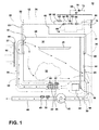
- FIG. 1 is a schematic view of a household appliance in the form of a clothes dryer 10 according to a first embodiment.
- the clothes dryer 10 of the illustrated embodiment may include a cabinet 12 defined by a front wall 18, a rear wall 20, and a pair of side walls 22 and 28 supporting a top wall 24.
- a door 26 may be hingedly mounted to the front wall 18 and may be selectively moveable between opened and closed positions to close an opening in the front wall 18, which provides access to the interior of the cabinet.
- a control panel or user interface 16 may include one or more knobs, switches, displays, and the like for communicating with the user, such as to receive input and provide output.
- the laundry treating appliance of FIG. 1 illustrated as a clothes dryer 10 is described and shown for illustrative purposes and is not intended to be limiting.
- the methods described herein may be used with any suitable laundry treating appliance and are not limited to use with clothes dryers.
- the laundry treating appliance may be any machine that treats fabrics, and examples of the laundry treating appliance may include, but are not limited to, a washing machine, including top-loading, front-loading, vertical axis, and horizontal axis washing machines; a dryer, such as a tumble dryer or a stationary dryer, including top-loading dryers and front-loading dryers; a combination washing machine and dryer; a tumbling or stationary refreshing/revitalizing machine; an extractor; a non-aqueous washing apparatus; and a revitalizing machine.
- a washing machine including top-loading, front-loading, vertical axis, and horizontal axis washing machines
- a dryer such as a tumble dryer or a stationary dryer, including top-loading dryers and front-loading
- laundry treating appliance and a method will be described with respect to a clothes dryer with the fabric being a laundry load, with it being understood that the invention may be adapted for use with other types of laundry treating appliance for treating fabric.
- laundry include, but are not limited to, a hat, a scarf, a glove, a sweater, a blouse, a shirt, a pair of shorts, a dress, a sock, a pair of pants, a shoe, an undergarment, and a jacket.
- textile fabrics in other products such as draperies, sheets, towels, pillows, and stuffed fabric articles (e.g., toys), may be dried in the clothes dryer 10.
- a rotatable drum 28 comprising a cylindrical wall terminating in a front edge and rear edge may be disposed within the interior of the cabinet 12 between opposing stationary rear and front bulkheads 30 and 32, which collectively define a drying chamber 34, for drying laundry.
- the drum 28 and bulkheads configuration may be of a different type, some non-limiting examples are: a closed end drum (for example, closed rear end), a non-stationary rear bulkhead or a non-stationary inlet grill type.
- the front bulkhead 30 may have an opening that aligns with the open face of the front wall 18.
- the drum 28 may have a circumference larger than that of the door 26 such that part of the front bulkhead 30 covers a portion of the front face of the drum 28.
- the door 26 may be in a closed position, it closes the face of the cabinet 12 and not the entire face of the drum 28.
- the drum 28 may be considered to be closed when the door 26 is in the closed position.
- the drum 28 may further optionally have one or more lifters or baffles 29.
- baffles 29 may be located along the inner surface of the drum 28 defining an interior circumference of the drum 28 and may be oriented generally parallel to a rotational axis of the drum 28.
- the baffles 29 facilitate the tumbling action of the fabric load within the drum 28 as the drum 28 rotates about the rotational axis.
- a textured surface may be used in place of or in addition to the baffles 29.
- An air flow system may be of any conventional type and is provided to draw air into and exhaust air from the treating chamber 34.
- the air flow system has a supply conduit 38 coupled to the treating chamber 34 by an inlet 40 in the rear bulkhead 32 and an exhaust conduit 44 coupled to the treating chamber 34 by a lint filter 45.
- a blower 46 is provided to first draw air through the inlet duct, into the heating chamber, and exhausting air from the heating chamber through the outlet duct.
- a heating element 42 may be provided within the inlet duct to heat the air as it passes through on the way to the treating chamber 34.
- a motor 54 may be coupled to the drum 28 through a belt 56 (or any other means for indirect drive such as a gearbox) and a drive shaft may rotate the drum 28.
- indirect drive are: three-phase induction motor drives, various types of single phase induction motors such as a permanent split capacitor (PSC), a shaded pole and a split-phase motor.
- the motor 54 may be a direct drive motor, as is known in the art.
- an applicable direct drive motor are: a brushless permanent magnet (BPM or BLDC) motor, an induction motor, etc.
- a dispensing system 57 may be provided to the clothes dryer 10 to dispense one or more treating chemistries to the treating chamber 34 according to a cycle of operation. As illustrated, the dispensing system 57 may be located in the interior of the cabinet 12 although other locations are also possible. The dispensing system 57 may be fluidly coupled to a water supply 68. The dispensing system 57 may be further coupled to the treating chamber 34 through one or more nozzles 69. As illustrated, nozzles 69 are provided to the front and rear of the treating chamber 34 to provide the treating chemistry or liquid to the interior of the treating chamber 34, although other configurations are also possible.
- the dispensing system 57 may include a reservoir 60, which may be a cartridge, for a treating chemistry that is releasably coupled to the dispensing system 57, which dispenses the treating chemistry from the reservoir 60 to the treating chamber 34.
- the reservoir 60 may include one or more cartridges configured to store one or more treating chemistries in the interior of cartridges.
- a suitable cartridge system may be found in U.S. Pub. No. 2010/0000022 to Hendrickson et al., filed July 1, 2008 , entitled "Household Cleaning Appliance with a Dispensing System Operable Between a Single Use Dispensing System and a Bulk Dispensing System".
- a mixing chamber 62 may be provided to couple the reservoir 60 to the treating chamber 34 through a supply conduit 63.
- Pumps such as a metering pump 64 and delivery pump 66 may be provided to the dispensing system 57 to selectively supply a treating chemistry and/or liquid to the treating chamber 34 according to a cycle of operation.
- the water supply 68 may be fluidly coupled to the mixing chamber 62 to provide water from the water source to the mixing chamber 62.
- the water supply 68 may include an inlet valve 70 and a water supply conduit 72. It is noted that, instead of water, a different treating chemistry may be provided from the exterior of the clothes dryer 10 to the mixing chamber 62.
- the treating chemistry may be any type of aid for treating laundry, non-limiting examples of which include, but are not limited to, water, fabric softeners, sanitizing agents, de-wrinkling or anti-wrinkling agents, and chemicals for imparting desired properties to the laundry, including stain resistance, fragrance (e.g., perfumes), insect repellency, and UV protection.
- aid for treating laundry non-limiting examples of which include, but are not limited to, water, fabric softeners, sanitizing agents, de-wrinkling or anti-wrinkling agents, and chemicals for imparting desired properties to the laundry, including stain resistance, fragrance (e.g., perfumes), insect repellency, and UV protection.
- the dryer 10 may also be provided with a steam generating system 80 which may be separate from the dispensing system 57 or integrated with portions of the dispensing system 57 for dispensing steam and/or liquid to the treating chamber 34 according to a cycle of operation.
- the steam generating system 80 may include a steam generator 82 fluidly coupled with the water supply 68 through a steam inlet conduit 84.
- a fluid control valve 85 may be used to control the flow of water from the water supply conduit 72 between the steam generating system 80 and the dispensing system 57.
- the steam generator 82 may further be fluidly coupled with the one or more supply conduits 63 through a steam supply conduit 86 to deliver steam to the treating chamber 34 through the nozzles 69.
- the steam generator 82 may be coupled with the treating chamber 34 through one or more conduits and nozzles independently of the dispensing system 57.
- the steam generator 82 may be any type of device that converts the supplied liquid to steam.
- the steam generator 82 may be a tank-type steam generator that stores a volume of liquid and heats the volume of liquid to convert the liquid to steam.
- the steam generator 82 may be an in-line steam generator that converts the liquid to steam as the liquid flows through the steam generator 82.
- any suitable dispensing system and/or steam generating system may be used with the dryer 10. It is also within the scope of the invention for the dryer 10 to not include a dispensing system or a steam generating system.
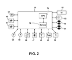
- FIG. 2 is a schematic view of the controller 14 coupled to the various components of the dryer 10.
- the controller 14 may be communicably coupled to components of the clothes dryer 10 such as the heating element 42, blower 46, thermistor 47, thermostat 48, thermal fuse 49, thermistor 51, moisture sensor 50, motor 54, inlet valve 70, pumps 64, 66, steam generator 82 and fluid control valve 85 to either control these components and/or receive their input for use in controlling the components.
- the controller 14 is also operably coupled to the user interface 16 to receive input from the user through the user interface 16 for the implementation of the drying cycle and provide the user with information regarding the drying cycle.
- the user interface 16 may be provided having operational controls such as dials, lights, knobs, levers, buttons, switches, and displays enabling the user to input commands to a controller 14 and receive information about a treatment cycle from components in the clothes dryer 10 or via input by the user through the user interface 16.
- the user may enter many different types of information, including, without limitation, cycle selection and cycle parameters, such as cycle options. Any suitable cycle may be used. Non-limiting examples include: Casual, Delicate, Super Delicate, Heavy Duty, Normal Dry, Damp Dry, Sanitize, Quick Dry, Timed Dry, and Jeans.
- the controller 14 may implement a treatment cycle selected by the user according to any options selected by the user and provide related information to the user.
- the controller 14 may also comprise a central processing unit (CPU) 74 and an associated memory 76 where various treatment cycles and associated data, such as look-up tables, may be stored.
- One or more software applications such as an arrangement of executable commands/instructions may be stored in the memory and executed by the CPU 74 to implement the one or more treatment cycles.
- the controller 14 will effect a cycle of operation to effect a treating of the laundry in the treating chamber 34, which may or may not include drying.
- the controller 14 may actuate the blower 46 to draw an inlet air flow 58 into the supply conduit 38 through the rear vent 37 when air flow is needed for a selected treating cycle.
- the controller 14 may activate the heating element 42 to heat the inlet air flow 58 as it passes over the heating element 42, with the heated air 59 being supplied to the treating chamber 34.
- the heated air 59 may be in contact with a laundry load 36 as it passes through the treating chamber 34 on its way to the exhaust conduit 44 to effect a moisture removal of the laundry.
- the heated air 59 may exit the treating chamber 34, and flow through the blower 46 and the exhaust conduit 44 to the outside of the clothes dryer 10.
- the controller 14 continues the cycle of operation until completed. If the cycle of operation includes drying, the controller 14 determines when the laundry is dry. The determination of a "dry" load may be made in different ways, but is often based on the moisture content of the laundry, which is typically set by the user based on the selected cycle, an option to the selected cycle, or a user-defined preference.
- FIG. 3 is an exploded view of the clothes dryer 10 including the front bulkhead 30, a front seal 100, the dryer drum 28, a rear seal 100, and the rear bulkhead 32 respectively.
- a half channel 31, 33 is formed in each of the front and rear bulkheads 30, 32, respectively.
- the dryer drum 28 terminates in opposing front and rear lips 103 to which the seals 100 are mounted, such as in an interference fit, like a slide-on, press-fit or snap-fit connection.
- the lip 103 within the seal 100 is then correspondingly received within the half channels 31, where the seal 100 abuts the corresponding bulkhead 32 to seal the drum 28 relative to the bulkhead 32.
- the seals 100 as illustrated, do not form a continuous loop and terminate in opposing ends having a confronting relationship with each other which leaves an intervening gap 101.
- a spacer 102 is located within the gap 101.
- the seals 100 do not form a complete loop because the seals 100 are made from a material that thermally expands/contracts. Depending on the size of the clothes dryer 10, the seals 100 may have a length of 1,83 m to 2,44 m (6 to 8 feet), which can lead to a length extension of up to 2,54 cm (1 inch) when the seal thermally expands under the temperatures encountered in the clothes dryer 10. This amount of thermal expansion renders impractical a continuous loop configuration for the thermal seals 100. Thus, a linear configuration is contemplated for the seals 100, with the spacer 102 filling in the gap between the ends.
- a coupler illustrated in one example as a pin 109, is provided to couple the opposing ends of the seal 100 and provide a support for mounting the spacer 102.
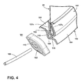
- the seal 100 comprises a body 105 in which is formed an aperture 108.
- the seal 100 includes an attachment 107 in the form of fingers 107a, 107b extending from the body 105 and defining an intervening recess 106, which is sized to match the profile of the lip 103.
- the fingers 107a, 107b are shaped such that they have to be deflected when the lip 103 is received within the annular recess 106 resulting in a compression force between fingers 107a and 107b.
- the lip 103 is enlarged near the tip, the addition of the compression force will aid in retaining the seal 100 to the lip 103.
- the seal 100 further includes flexible wings 104 which extend out from the body 105, which are used to form a seal relative to the corresponding bulkhead 30, 32. While two wings 104 are illustrated, fewer or more wings can be used. The wings 104 can be arranged such that they form an axial and/or radial seal between the corresponding pairs of bulkhead 30, 32 and lip 103.
- the spacer 102 has a passageway 110, which is sized to receive the pin 109.
- the spacer 102 can have any variable shape that allows for the filling of the gap 101 in response to the changing size of the space 101 caused by the thermal expansion/contraction of the seal 100.
- the spacer 102 is made from a sheet of folded material, folded on itself and sewn or in an accordion fold, that provides the spacer with the ability to vary its shape in response to a change in the gap 101. In the folded-body configuration, the spacer 102 can be made out of felt or any other material capable of being folded.
- the pin 109 is sized to be received within the apertures 108 of the opposing ends of the seal 100 and passing through the passageway 110 of the spacer.
- the pin 109 can be made of steel, plastic, or any suitable material capable of being bent to follow the same radius as the dryer drum 28.
- the pin 109 only needs to be long enough to span the gap 101 formed when the seal 100 terminates in opposing ends while remaining fixed in the apertures 108.
- the relationship between the pin 109, the apertures 108, and passageway 110 is such that the pin does not deleteriously interfere with the thermal expansion/contraction of the seal 100 or the changing of shape of the spacer 102.
- FIG. 5 is an assembled view of the coupler, as a pin 109, holding the spacer 102, along with the seal 100 mounted to the lip 103.
- the pin 109 spans the gap 101 by coupling one end of the seal 100 to the opposing end. While not shown in FIG. 5 , the other opposing end is a mirror image of the opposing end that is shown and includes a corresponding aperture 108 in which the pin 109 is received.
- the spacer 102 When assembled, the spacer 102 is provided between the opposing ends of the seal 100 and is mounted to the pin 109.
- the pin 109 slides through the passageway 110 of the spacer 102 and is fixed in the aperture 108 of the seal 100 so that the pin 109 holds the spacer 102 in place between the opposing ends of the seal 100.
- a person or machine presses the seal 100 over the lip 103 such that the recess 106 of the attachment 107 receives the lip 103, with the fingers 107a, 107 b applying a compression force to the lip 103 to aid in retaining the seal 100 to the lip 103.
- the spacer 102 and pin 109 can be mounted to the seal before or after the seal 100 is mounted to the lip lip 103. In either case, the pin 109 is inserted into the apertures 108 of the opposing ends of the seal 100 and inserted through the passageway 110 of the spacer 102.
- the spacer 102 can be mounted to the pin 109 before either end of the pin 109 is inserted into the aperture 108 of the seal 100 or after one end of the pin 109 is inserted into one of the apertures 108.
- the spacer 102 and pin 109 will be mounted to the seal 100 prior to the mounting of the seal 100 to the lip 103.
- the drum 28 and bulkheads 30, 32 are known to have some relative movement or "play", which can lead to a relative shift in the position of the drum 28 to one or more of the bulkheads 30, 32.
- a common scenario where such a shift can occur is during the initial rotation of the drum 28 with a wet clothes load.
- the clothes load has its greatest mass, which, alone, is sufficient to cause the drum 28 to move both radially along axis R (see FIG. 3 ) and axially along axis A (see FIG. 3 ).
- the drum 28 is rotated while heated air is passed through the drum 28 to tumble dry the clothes load.
- the tumbling of the clothes load results in a repeated release and application of a force on the drum 28, which can also relatively move the drum 28 radially and axially relative to the bulkhead 30, 32.
- the seal 100 can accommodate the relative movement of the drum 28 and the bulkhead 30, 32 through flexible wings 104, which are configured and shaped in such a way that they can flex to accommodate the relative change in position of the drum 28 and bulkhead 30, 32.
- FIG. 7 illustrates a scenario where the drum 28 is radially shifted toward the bulkhead 30, 32. In this position, one of the wings 104 forming the radial seal in a pinched, flexed position while still maintaining a continuous seal along the bulkhead 30, 32.
- FIG. 8 illustrates a scenario wherein the drum 28 is radially shifted away from the bulkhead 30, 32 and the same radial wing from FIG. 7 is in an extended, more relaxed position, while still maintaining a continuous seal along the bulkhead 30, 32.
- FIGS. 7 and 8 together illustrate how with movement of the drum 28, the wings 104 are allowed to flex and extend while still maintaining a continuous seal along the bulkhead 30, 32.
- the seal is also allowed to slide along the bulkhead 30, 32 shown in that side 104a is not visible in FIG. 7 but becomes visible in FIG. 8 due to sliding.
- the seal 100 can be coated with a low friction surface along the side 104a or it can be co-extruded during production to include two different materials, one being a low friction surface for the side in contact with the bulkhead 30, 32.
Landscapes
- Engineering & Computer Science (AREA)
- Textile Engineering (AREA)
- Detail Structures Of Washing Machines And Dryers (AREA)
Abstract
Description
- Contemporary laundry treating appliances include clothes dryers that utilize a heating element, such as a gas or electric heater or a heat pump, to heat air forced through the clothes dryer to dry a load of washed clothes. Contemporary laundry treating appliances can also include condensing dryers. Traditionally, clothes dryers can include a cylindrical drum held between opposing bulkheads with a felt seal along the interface between the drum and to bulkheads to retain the heated air during the drying cycle. The loss of heated air through the interface can negatively impact the drying time and lead to resource waste.
- In one embodiment, the invention relates to a clothes dryer having at least one bulkhead, and a drum with a peripheral wall terminating in an edge having a circumferential lip defining an open end and proximate the at least one bulkhead. A seal having opposing ends and a wing, wherein the seal is mounted about the circumferential lip to define a gap between the opposing ends and the wing abuts the bulkhead to seal the drum relative to the bulkhead. A variable shape spacer located within the gap. The body is made of thermally expanding material such that the gap varies in length depending on the thermal expansion of the seal and the spacer varies in shape in response to the gap varying to occlude the intervening gap.
- In the drawings:
-
FIG. 1 is a schematic view of a clothes dryer. -
FIG. 2 is a schematic of a control system for the dryer ofFIG. 1 . -
FIG. 3 is an exploded view of a front bulkhead, front seal, dryer drum, rear seal, and rear bulkhead for the household appliance ofFIG 1 . -
FIG. 4 is an exploded view of a partial and enlarged cross section of the dryer drum and bulkhead with a profile of the seal shown in place including the connector pin which spans the gap created when the seal is in place and the spacer that the pin holds in place to fill the gap. -
FIG. 5 is a partial and enlarged cross section of the dryer drum and bulkhead with a profile of the seal, connector pin, and spacer shown assembled. -
FIG.6 is a first orientation of the seal with the flexible wings pinched against the bulkhead in the radial direction. -
FIG. 7 is a second orientation of the seal with the flexible wings shown extended and still abutting up against the bulkhead in the radial direction. -
FIG. 1 is a schematic view of a household appliance in the form of aclothes dryer 10 according to a first embodiment. Theclothes dryer 10 of the illustrated embodiment may include acabinet 12 defined by afront wall 18, arear wall 20, and a pair ofside walls top wall 24. Adoor 26 may be hingedly mounted to thefront wall 18 and may be selectively moveable between opened and closed positions to close an opening in thefront wall 18, which provides access to the interior of the cabinet. A control panel oruser interface 16 may include one or more knobs, switches, displays, and the like for communicating with the user, such as to receive input and provide output. - The laundry treating appliance of
FIG. 1 illustrated as aclothes dryer 10 is described and shown for illustrative purposes and is not intended to be limiting. The methods described herein may be used with any suitable laundry treating appliance and are not limited to use with clothes dryers. The laundry treating appliance may be any machine that treats fabrics, and examples of the laundry treating appliance may include, but are not limited to, a washing machine, including top-loading, front-loading, vertical axis, and horizontal axis washing machines; a dryer, such as a tumble dryer or a stationary dryer, including top-loading dryers and front-loading dryers; a combination washing machine and dryer; a tumbling or stationary refreshing/revitalizing machine; an extractor; a non-aqueous washing apparatus; and a revitalizing machine. For illustrative purposes, the laundry treating appliance and a method will be described with respect to a clothes dryer with the fabric being a laundry load, with it being understood that the invention may be adapted for use with other types of laundry treating appliance for treating fabric. Examples of laundry include, but are not limited to, a hat, a scarf, a glove, a sweater, a blouse, a shirt, a pair of shorts, a dress, a sock, a pair of pants, a shoe, an undergarment, and a jacket. Furthermore, textile fabrics in other products, such as draperies, sheets, towels, pillows, and stuffed fabric articles (e.g., toys), may be dried in theclothes dryer 10. - A
rotatable drum 28 comprising a cylindrical wall terminating in a front edge and rear edge may be disposed within the interior of thecabinet 12 between opposing stationary rear andfront bulkheads drying chamber 34, for drying laundry. Alternatively, thedrum 28 and bulkheads configuration may be of a different type, some non-limiting examples are: a closed end drum (for example, closed rear end), a non-stationary rear bulkhead or a non-stationary inlet grill type. - The
front bulkhead 30 may have an opening that aligns with the open face of thefront wall 18. Thedrum 28 may have a circumference larger than that of thedoor 26 such that part of thefront bulkhead 30 covers a portion of the front face of thedrum 28. Thus, when thedoor 26 may be in a closed position, it closes the face of thecabinet 12 and not the entire face of thedrum 28. However, thedrum 28 may be considered to be closed when thedoor 26 is in the closed position. - The
drum 28 may further optionally have one or more lifters orbaffles 29. In most dryers, there are multiple baffles. Thebaffles 29 may be located along the inner surface of thedrum 28 defining an interior circumference of thedrum 28 and may be oriented generally parallel to a rotational axis of thedrum 28. Thebaffles 29 facilitate the tumbling action of the fabric load within thedrum 28 as thedrum 28 rotates about the rotational axis. Alternatively, a textured surface may be used in place of or in addition to thebaffles 29. - An air flow system may be of any conventional type and is provided to draw air into and exhaust air from the treating
chamber 34. As illustrated, the air flow system has asupply conduit 38 coupled to the treatingchamber 34 by aninlet 40 in therear bulkhead 32 and anexhaust conduit 44 coupled to the treatingchamber 34 by alint filter 45. Ablower 46 is provided to first draw air through the inlet duct, into the heating chamber, and exhausting air from the heating chamber through the outlet duct. Aheating element 42 may be provided within the inlet duct to heat the air as it passes through on the way to the treatingchamber 34. - A
motor 54 may be coupled to thedrum 28 through a belt 56 (or any other means for indirect drive such as a gearbox) and a drive shaft may rotate thedrum 28. Some non-limiting examples of indirect drive are: three-phase induction motor drives, various types of single phase induction motors such as a permanent split capacitor (PSC), a shaded pole and a split-phase motor. Alternately, themotor 54 may be a direct drive motor, as is known in the art. Some non-limiting examples of an applicable direct drive motor are: a brushless permanent magnet (BPM or BLDC) motor, an induction motor, etc. - A
dispensing system 57 may be provided to theclothes dryer 10 to dispense one or more treating chemistries to the treatingchamber 34 according to a cycle of operation. As illustrated, thedispensing system 57 may be located in the interior of thecabinet 12 although other locations are also possible. Thedispensing system 57 may be fluidly coupled to awater supply 68. Thedispensing system 57 may be further coupled to the treatingchamber 34 through one ormore nozzles 69. As illustrated,nozzles 69 are provided to the front and rear of the treatingchamber 34 to provide the treating chemistry or liquid to the interior of the treatingchamber 34, although other configurations are also possible. - As illustrated, the
dispensing system 57 may include areservoir 60, which may be a cartridge, for a treating chemistry that is releasably coupled to thedispensing system 57, which dispenses the treating chemistry from thereservoir 60 to the treatingchamber 34. Thereservoir 60 may include one or more cartridges configured to store one or more treating chemistries in the interior of cartridges. A suitable cartridge system may be found inU.S. Pub. No. 2010/0000022 to Hendrickson et al., filed July 1, 2008 , entitled "Household Cleaning Appliance with a Dispensing System Operable Between a Single Use Dispensing System and a Bulk Dispensing System". - A
mixing chamber 62 may be provided to couple thereservoir 60 to the treatingchamber 34 through asupply conduit 63. Pumps such as ametering pump 64 anddelivery pump 66 may be provided to thedispensing system 57 to selectively supply a treating chemistry and/or liquid to the treatingchamber 34 according to a cycle of operation. Thewater supply 68 may be fluidly coupled to themixing chamber 62 to provide water from the water source to themixing chamber 62. Thewater supply 68 may include aninlet valve 70 and awater supply conduit 72. It is noted that, instead of water, a different treating chemistry may be provided from the exterior of theclothes dryer 10 to themixing chamber 62. - The treating chemistry may be any type of aid for treating laundry, non-limiting examples of which include, but are not limited to, water, fabric softeners, sanitizing agents, de-wrinkling or anti-wrinkling agents, and chemicals for imparting desired properties to the laundry, including stain resistance, fragrance (e.g., perfumes), insect repellency, and UV protection.
- The
dryer 10 may also be provided with asteam generating system 80 which may be separate from thedispensing system 57 or integrated with portions of thedispensing system 57 for dispensing steam and/or liquid to the treatingchamber 34 according to a cycle of operation. Thesteam generating system 80 may include asteam generator 82 fluidly coupled with thewater supply 68 through asteam inlet conduit 84. Afluid control valve 85 may be used to control the flow of water from thewater supply conduit 72 between thesteam generating system 80 and the dispensingsystem 57. Thesteam generator 82 may further be fluidly coupled with the one ormore supply conduits 63 through asteam supply conduit 86 to deliver steam to the treatingchamber 34 through thenozzles 69. Alternatively, thesteam generator 82 may be coupled with the treatingchamber 34 through one or more conduits and nozzles independently of the dispensingsystem 57. - The
steam generator 82 may be any type of device that converts the supplied liquid to steam. For example, thesteam generator 82 may be a tank-type steam generator that stores a volume of liquid and heats the volume of liquid to convert the liquid to steam. Alternatively, thesteam generator 82 may be an in-line steam generator that converts the liquid to steam as the liquid flows through thesteam generator 82. - It will be understood that any suitable dispensing system and/or steam generating system may be used with the
dryer 10. It is also within the scope of the invention for thedryer 10 to not include a dispensing system or a steam generating system. - Referring now to
FIG. 2 , which is a schematic view of thecontroller 14 coupled to the various components of thedryer 10. Thecontroller 14 may be communicably coupled to components of theclothes dryer 10 such as theheating element 42,blower 46,thermistor 47,thermostat 48,thermal fuse 49,thermistor 51,moisture sensor 50,motor 54,inlet valve 70, pumps 64, 66,steam generator 82 andfluid control valve 85 to either control these components and/or receive their input for use in controlling the components. Thecontroller 14 is also operably coupled to theuser interface 16 to receive input from the user through theuser interface 16 for the implementation of the drying cycle and provide the user with information regarding the drying cycle. - The
user interface 16 may be provided having operational controls such as dials, lights, knobs, levers, buttons, switches, and displays enabling the user to input commands to acontroller 14 and receive information about a treatment cycle from components in theclothes dryer 10 or via input by the user through theuser interface 16. The user may enter many different types of information, including, without limitation, cycle selection and cycle parameters, such as cycle options. Any suitable cycle may be used. Non-limiting examples include: Casual, Delicate, Super Delicate, Heavy Duty, Normal Dry, Damp Dry, Sanitize, Quick Dry, Timed Dry, and Jeans. - The
controller 14 may implement a treatment cycle selected by the user according to any options selected by the user and provide related information to the user. Thecontroller 14 may also comprise a central processing unit (CPU) 74 and an associatedmemory 76 where various treatment cycles and associated data, such as look-up tables, may be stored. One or more software applications, such as an arrangement of executable commands/instructions may be stored in the memory and executed by theCPU 74 to implement the one or more treatment cycles. - In general, the
controller 14 will effect a cycle of operation to effect a treating of the laundry in the treatingchamber 34, which may or may not include drying. Thecontroller 14 may actuate theblower 46 to draw aninlet air flow 58 into thesupply conduit 38 through therear vent 37 when air flow is needed for a selected treating cycle. Thecontroller 14 may activate theheating element 42 to heat theinlet air flow 58 as it passes over theheating element 42, with theheated air 59 being supplied to the treatingchamber 34. Theheated air 59 may be in contact with alaundry load 36 as it passes through the treatingchamber 34 on its way to theexhaust conduit 44 to effect a moisture removal of the laundry. Theheated air 59 may exit the treatingchamber 34, and flow through theblower 46 and theexhaust conduit 44 to the outside of theclothes dryer 10. Thecontroller 14 continues the cycle of operation until completed. If the cycle of operation includes drying, thecontroller 14 determines when the laundry is dry. The determination of a "dry" load may be made in different ways, but is often based on the moisture content of the laundry, which is typically set by the user based on the selected cycle, an option to the selected cycle, or a user-defined preference. -
FIG. 3 is an exploded view of theclothes dryer 10 including thefront bulkhead 30, afront seal 100, thedryer drum 28, arear seal 100, and therear bulkhead 32 respectively. Ahalf channel rear bulkheads dryer drum 28 terminates in opposing front andrear lips 103 to which theseals 100 are mounted, such as in an interference fit, like a slide-on, press-fit or snap-fit connection. Thelip 103 within theseal 100 is then correspondingly received within thehalf channels 31, where theseal 100 abuts the correspondingbulkhead 32 to seal thedrum 28 relative to thebulkhead 32. Theseals 100, as illustrated, do not form a continuous loop and terminate in opposing ends having a confronting relationship with each other which leaves an interveninggap 101. Aspacer 102 is located within thegap 101. - The
seals 100 do not form a complete loop because theseals 100 are made from a material that thermally expands/contracts. Depending on the size of theclothes dryer 10, theseals 100 may have a length of 1,83 m to 2,44 m (6 to 8 feet), which can lead to a length extension of up to 2,54 cm (1 inch) when the seal thermally expands under the temperatures encountered in theclothes dryer 10. This amount of thermal expansion renders impractical a continuous loop configuration for the thermal seals 100. Thus, a linear configuration is contemplated for theseals 100, with thespacer 102 filling in the gap between the ends. A coupler, illustrated in one example as apin 109, is provided to couple the opposing ends of theseal 100 and provide a support for mounting thespacer 102. - Referring to
FIG. 4 , the details of theseal 100,spacer 102 andpin 109 is better illustrated in the context of one of the opposing ends of the seal. Theseal 100 comprises abody 105 in which is formed anaperture 108. Theseal 100 includes anattachment 107 in the form offingers body 105 and defining anintervening recess 106, which is sized to match the profile of thelip 103. Thefingers lip 103 is received within theannular recess 106 resulting in a compression force betweenfingers lip 103 is enlarged near the tip, the addition of the compression force will aid in retaining theseal 100 to thelip 103. - The
seal 100 further includesflexible wings 104 which extend out from thebody 105, which are used to form a seal relative to the correspondingbulkhead wings 104 are illustrated, fewer or more wings can be used. Thewings 104 can be arranged such that they form an axial and/or radial seal between the corresponding pairs ofbulkhead lip 103. - The
spacer 102 has apassageway 110, which is sized to receive thepin 109. Thespacer 102 can have any variable shape that allows for the filling of thegap 101 in response to the changing size of thespace 101 caused by the thermal expansion/contraction of theseal 100. As illustrated, thespacer 102 is made from a sheet of folded material, folded on itself and sewn or in an accordion fold, that provides the spacer with the ability to vary its shape in response to a change in thegap 101. In the folded-body configuration, thespacer 102 can be made out of felt or any other material capable of being folded. - The
pin 109 is sized to be received within theapertures 108 of the opposing ends of theseal 100 and passing through thepassageway 110 of the spacer. Thepin 109 can be made of steel, plastic, or any suitable material capable of being bent to follow the same radius as thedryer drum 28. Thepin 109 only needs to be long enough to span thegap 101 formed when theseal 100 terminates in opposing ends while remaining fixed in theapertures 108. The relationship between thepin 109, theapertures 108, andpassageway 110 is such that the pin does not deleteriously interfere with the thermal expansion/contraction of theseal 100 or the changing of shape of thespacer 102. -
FIG. 5 is an assembled view of the coupler, as apin 109, holding thespacer 102, along with theseal 100 mounted to thelip 103. Thepin 109 spans thegap 101 by coupling one end of theseal 100 to the opposing end. While not shown inFIG. 5 , the other opposing end is a mirror image of the opposing end that is shown and includes acorresponding aperture 108 in which thepin 109 is received. - When assembled, the
spacer 102 is provided between the opposing ends of theseal 100 and is mounted to thepin 109. Thepin 109 slides through thepassageway 110 of thespacer 102 and is fixed in theaperture 108 of theseal 100 so that thepin 109 holds thespacer 102 in place between the opposing ends of theseal 100. - To install the
seal 100, a person or machine presses theseal 100 over thelip 103 such that therecess 106 of theattachment 107 receives thelip 103, with thefingers lip 103 to aid in retaining theseal 100 to thelip 103. - The
spacer 102 and pin 109 can be mounted to the seal before or after theseal 100 is mounted to thelip lip 103. In either case, thepin 109 is inserted into theapertures 108 of the opposing ends of theseal 100 and inserted through thepassageway 110 of thespacer 102. Thespacer 102 can be mounted to thepin 109 before either end of thepin 109 is inserted into theaperture 108 of theseal 100 or after one end of thepin 109 is inserted into one of theapertures 108. For ease of final assembly, it is contemplated that thespacer 102 and pin 109 will be mounted to theseal 100 prior to the mounting of theseal 100 to thelip 103. - The general sealing function of the
seal 100 will now be described with respect toFIGS. 6 and 7 . In the expected environment for theseal 100, thedrum 28 andbulkheads drum 28 to one or more of thebulkheads drum 28 with a wet clothes load. When the clothes are wet, the clothes load has its greatest mass, which, alone, is sufficient to cause thedrum 28 to move both radially along axis R (seeFIG. 3 ) and axially along axis A (seeFIG. 3 ). During drying, thedrum 28 is rotated while heated air is passed through thedrum 28 to tumble dry the clothes load. The tumbling of the clothes load results in a repeated release and application of a force on thedrum 28, which can also relatively move thedrum 28 radially and axially relative to thebulkhead - The
seal 100 can accommodate the relative movement of thedrum 28 and thebulkhead flexible wings 104, which are configured and shaped in such a way that they can flex to accommodate the relative change in position of thedrum 28 andbulkhead -
FIG. 7 illustrates a scenario where thedrum 28 is radially shifted toward thebulkhead wings 104 forming the radial seal in a pinched, flexed position while still maintaining a continuous seal along thebulkhead - FIG. 8 illustrates a scenario wherein the
drum 28 is radially shifted away from thebulkhead FIG. 7 is in an extended, more relaxed position, while still maintaining a continuous seal along thebulkhead -
FIGS. 7 and 8 together illustrate how with movement of thedrum 28, thewings 104 are allowed to flex and extend while still maintaining a continuous seal along thebulkhead bulkhead side 104a is not visible inFIG. 7 but becomes visible in FIG. 8 due to sliding. - Furthermore the axial and radial movement which causes sliding is facilitated by a low friction surface along the
wing side 104a which is in contact with thebulkhead seal 100 to slide with the movement and shifting of thedrum 28. Theseal 100 can be coated with a low friction surface along theside 104a or it can be co-extruded during production to include two different materials, one being a low friction surface for the side in contact with thebulkhead - Benefits of this invention will now be described which include ease of assembly and reduced airflow loss. While the prior art comprises seals made entirely of felt, requiring an adhesive such as glue to install them, the extruded
drum seal 100 is easily placed due to its design in which the annular recess of the seal is molded to receive the lip of thedrum 28. When in place pressure variations in the drum cause the wings of the extrudeddrum seal 100 to self-seal which reduces the airflow loss compared to the prior art. The prior art felt seals can lose up to 30% of the airflow within thedryer drum 28 due to their inefficient sealing technology while the extrudeddrum seal 100 of the invention allows only 3% loss through the small spacer. Since the present invention is easier to assemble and reduces airflow losses, it also saves consumers in energy costs and contributes to shorter drying times. - While the invention has been specifically described in connection with certain specific embodiments thereof, it is to be understood that this is by way of illustration and not of limitation, and the scope of the appended claims should be construed as broadly as the prior art will permit.
Claims (12)
- A clothes dryer (10) comprising:a front bulkhead (30) having a door opening;a rear bulkhead (32);a drum (28) comprising a cylindrical wall (28) terminating in a front edge (103) proximate the front bulkhead (30) and a rear edge proximate the rear bulkhead (32), with a least one of the front and rear edges having a lip (103);a seal (100) having a body (105) terminating in opposing ends, the body (105) having an attachment (107) defining a recess (106) sized to receive the lip (103) to mount the seal (100) about the lip (103) and a seal (100) element abutting the corresponding front or rear bulkhead (32), wherein the body (105) has a length such that, when the body (105) is mounted to the lip (103), the opposing ends are in confronting relationship and define an intervening gap (101); anda variable shape spacer (102) located within the intervening gap (101);wherein the body (105) is made of thermally expanding material and the gap (101) varies in shape depending on the thermal expansion of the body (105) and the spacer (102) varies in shape in response to the gap (101) varying to occlude the intervening gap (101).
- The clothes dryer (10) of claim 1 further comprising a coupler (109) connecting the opposing ends.
- The clothes dryer (10) of claim 2 wherein the opposing ends comprise corresponding apertures (108) and the coupler comprises a pin (109) received within the apertures (108).
- The clothes dryer of claim 3 wherein the pin (109) spans the gap (101).
- The clothes dryer (10) of claim 1 wherein the seal (100) further comprises at least one wing (104) extending from the body (105) and abutting the corresponding front or rear bulkhead (32).
- The clothes dryer (10) of claim 5 wherein the at least one wing (104) forms at least one of an axial seal (100) or radial seal (100) with the corresponding front or rear bulkhead (32).
- The clothes dryer (10) of claim 6 wherein the at least one wing (104) comprises two wings, with one of the two wings (104) forming the axial seal (100) and the other of the two wings (104) forming the radial seal (100).
- The clothes dryer (10) of claim 5 wherein the wing (104) comprises a low friction surface abutting the bulkhead (30, 32).
- The clothes dryer (10) of claim 8 wherein the wing is made of a first material and the low friction surface is a second material, which is different from the first material.
- The clothes dryer (10) of claim 1 wherein the spacer (102) comprises a sheet of folded material.
- The clothes dryer (10) of claim 10 wherein the sheet of folded material is accordion folded.
- The clothes dryer (10) of claim 1 wherein the each of the front and rear edges comprises a lip (103) to define a front lip and a rear lip, and the at least one seal (100) comprises a first seal (100) and a second seal (100), wherein the first seal (100) is mounted to the first lip and the second seal (100) is mounted to the second lip.
Applications Claiming Priority (1)
| Application Number | Priority Date | Filing Date | Title |
|---|---|---|---|
| US14/821,842 US9580856B1 (en) | 2015-08-10 | 2015-08-10 | Clothes dryer with a drum seal |
Publications (2)
| Publication Number | Publication Date |
|---|---|
| EP3130701A1 true EP3130701A1 (en) | 2017-02-15 |
| EP3130701B1 EP3130701B1 (en) | 2019-05-22 |
Family
ID=56557629
Family Applications (1)
| Application Number | Title | Priority Date | Filing Date |
|---|---|---|---|
| EP16182226.7A Not-in-force EP3130701B1 (en) | 2015-08-10 | 2016-08-01 | Clothes dryer with a drum seal |
Country Status (2)
| Country | Link |
|---|---|
| US (2) | US9580856B1 (en) |
| EP (1) | EP3130701B1 (en) |
Cited By (2)
| Publication number | Priority date | Publication date | Assignee | Title |
|---|---|---|---|---|
| US20170130388A1 (en) * | 2015-08-10 | 2017-05-11 | Whirlpool Corporation | Clothes dryer with a drum seal |
| IT201800010346A1 (en) * | 2018-11-15 | 2020-05-15 | Ilpea Ind Spa | GASKET FOR DRYER |
Families Citing this family (11)
| Publication number | Priority date | Publication date | Assignee | Title |
|---|---|---|---|---|
| US10458057B2 (en) * | 2017-06-27 | 2019-10-29 | Whirlpool Corporation | Clothes dryer with a foam seal |
| US11795601B2 (en) | 2020-11-10 | 2023-10-24 | Whirlpool Corporation | Maximizing the dry rate of clothes tumbling combination washer/dryer with a seal |
| US11846059B2 (en) | 2021-01-04 | 2023-12-19 | Whirlpool Corporation | Controlling process air bypass around the drum in combo wash-dry system |
| US20220282423A1 (en) * | 2021-03-04 | 2022-09-08 | Yit (Hk) Co., Limited | Clothes drying device |
| DE102021210225A1 (en) * | 2021-09-15 | 2023-03-16 | Dürr Systems Ag | Treatment station, treatment installation and method for treating workpieces |
| US11739465B2 (en) | 2021-12-13 | 2023-08-29 | Samsung Electronics Co., Ltd. | Combination washer-dryer with expandable drum |
| US12590394B2 (en) | 2022-09-19 | 2026-03-31 | Whirlpool Corporation | Air bypass seal with backer for improved drying performance in a combination washer/dryer |
| EP4686780A1 (en) * | 2024-07-30 | 2026-02-04 | BSH Hausgeräte GmbH | Laundry dryer comprising a sealing |
| WO2026081902A1 (en) * | 2024-10-15 | 2026-04-23 | 追觅创新科技(苏州)有限公司 | Clothes dryer |
| DE202024106858U1 (en) | 2024-11-26 | 2026-04-23 | BSH Hausgeräte GmbH | Laundry treatment machine with a profile arrangement |
| DE202024106857U1 (en) | 2024-11-26 | 2026-04-23 | BSH Hausgeräte GmbH | Profile arrangement for laundry treatment machines |
Citations (7)
| Publication number | Priority date | Publication date | Assignee | Title |
|---|---|---|---|---|
| US2970717A (en) * | 1959-01-14 | 1961-02-07 | Gen Electric | Door gasketing arrangement |
| US3816942A (en) * | 1972-07-24 | 1974-06-18 | Maytag Co | Bulkhead seal for clothes dryer |
| GB1454135A (en) * | 1973-03-26 | 1976-10-27 | Schlegel Mfg Co | Seal and sealing element for a clothes drier |
| US20040159010A1 (en) * | 2002-12-02 | 2004-08-19 | Hwang Sung Gi | Laundry dryer |
| US20100000022A1 (en) | 2008-07-01 | 2010-01-07 | Whirlpool Corporation | Household cleaning appliance with a dispensing system operable between a single use dispensing system and a bulk dispensing system |
| EP2385167A1 (en) * | 2010-05-05 | 2011-11-09 | Miele & Cie. KG | Drum laundry dryer |
| US20140327212A1 (en) * | 2013-04-01 | 2014-11-06 | Felters Of South Carolina, Llc | Fire retardant high temperature dryer seals and related methods |
Family Cites Families (37)
| Publication number | Priority date | Publication date | Assignee | Title |
|---|---|---|---|---|
| US3089327A (en) * | 1951-09-07 | 1963-05-14 | Murray Corp | Apparatus for the complete laundering of fabrics |
| BE660007A (en) * | 1964-02-25 | 1965-08-19 | ||
| US3270529A (en) * | 1964-02-25 | 1966-09-06 | Hupp Corp | Laundry equipment |
| US3409997A (en) | 1965-01-13 | 1968-11-12 | Whirlpool Co | Dryer with open end drum |
| US3570138A (en) * | 1968-11-12 | 1971-03-16 | Blackstone Corp | Clothes dryers |
| US3637224A (en) * | 1969-02-27 | 1972-01-25 | Fedders Corp | Annular sealing ring |
| US3875686A (en) * | 1974-01-28 | 1975-04-08 | Schlegel Mfg Co | Seal for clothes dryer |
| FR2454980B1 (en) * | 1979-04-24 | 1985-06-21 | Expandet Sa | PLASTIC HAIRDRESSER FOR FUT |
| IT8034002V0 (en) * | 1980-01-11 | 1980-01-11 | Zanussi Grandi Impianti Spa | DOOR FOR INDUSTRIAL TYPE WASHING MACHINES. |
| US4430809A (en) | 1981-11-24 | 1984-02-14 | Whirlpool Corporation | Front drum access and support for dryer |
| US4669200A (en) * | 1985-11-27 | 1987-06-02 | Whirlpool Corporation | Bulkhead seal for clothes dryer |
| US5127169A (en) * | 1991-01-25 | 1992-07-07 | Maytag Corporation | Clothes dryer |
| US5062219A (en) * | 1991-02-12 | 1991-11-05 | Speed Queen Company | Air flow apparatus for clothes dryer |
| US5216823A (en) * | 1992-03-17 | 1993-06-08 | White Consolidated Industries, Inc. | Bearing and seal assembly for clothes dryer drum |
| US5363569A (en) * | 1993-03-11 | 1994-11-15 | White Consolidated Industries, Inc. | Bearing and seal assembly for clothes dryer drum |
| DE19503367C2 (en) * | 1995-02-02 | 2002-04-25 | Bsh Bosch Siemens Hausgeraete | Sealing arrangement for a household clothes dryer |
| US5548908A (en) * | 1995-06-13 | 1996-08-27 | White Consolidated Industries, Inc. | Bulkhead and expanded drum without rollers |
| US5509669A (en) * | 1995-06-19 | 1996-04-23 | General Electric Company | Gas-path leakage seal for a gas turbine |
| SE508291C2 (en) * | 1997-01-20 | 1998-09-21 | Electrolux Ab | Washing machine with bottom valve and level sensing means |
| US5979195A (en) * | 1998-05-15 | 1999-11-09 | Maytag Corporation | Seal arrangement between inner and outer tubs of a horizontal axis washing machine |
| US6675496B1 (en) * | 2002-08-01 | 2004-01-13 | The Felters Company | Dryer drum bearing assembly |
| US7627960B2 (en) * | 2003-06-30 | 2009-12-08 | General Electric Company | Clothes dryer drum projections |
| US7007955B2 (en) * | 2003-07-25 | 2006-03-07 | The Felters Group | Dryer seal |
| KR101093878B1 (en) * | 2004-06-05 | 2011-12-13 | 엘지전자 주식회사 | Drum device of dryer |
| US20070044342A1 (en) | 2005-08-01 | 2007-03-01 | John Burns | Dryer seal |
| US20070074419A1 (en) | 2005-09-30 | 2007-04-05 | David Starrett | Multi-layer dryer seal |
| EP1957262A4 (en) * | 2005-11-21 | 2011-08-10 | Oshkosh Corp | Expandable joint |
| US8539694B2 (en) * | 2007-08-03 | 2013-09-24 | Lg Electronics Inc. | Clothes treatment apparatus |
| CA2604671A1 (en) * | 2007-09-28 | 2009-03-28 | Mabe Canada Inc. | Clothes dryer bearing gasket support |
| KR101308510B1 (en) * | 2007-11-05 | 2013-09-12 | 동부대우전자 주식회사 | Dryer having indrawn tube with heater |
| US8069582B2 (en) * | 2007-12-27 | 2011-12-06 | Daewoo Electronics Corporation | Dryer |
| US8127464B2 (en) * | 2009-07-31 | 2012-03-06 | Bsh Home Appliances Corporation | Front ring for a household appliance door |
| EP2423375B1 (en) * | 2010-08-24 | 2015-12-02 | Electrolux Home Products Corporation N.V. | Rotary-drum laundry dryer |
| BE1019306A5 (en) * | 2010-11-25 | 2012-05-08 | Medibeg N V | CUFF FOR WASHING MACHINE. |
| US8875416B2 (en) * | 2012-04-24 | 2014-11-04 | Whirlpool Corporation | Laundry treating appliance door with planar window element and projection |
| US9970705B2 (en) * | 2013-04-01 | 2018-05-15 | Felters Of South Carolina, Llc | High temperature dryer seals and related methods |
| US9580856B1 (en) * | 2015-08-10 | 2017-02-28 | Whirlpool Corporation | Clothes dryer with a drum seal |
-
2015
- 2015-08-10 US US14/821,842 patent/US9580856B1/en not_active Expired - Fee Related
-
2016
- 2016-08-01 EP EP16182226.7A patent/EP3130701B1/en not_active Not-in-force
-
2017
- 2017-01-20 US US15/411,089 patent/US10066336B2/en not_active Expired - Fee Related
Patent Citations (7)
| Publication number | Priority date | Publication date | Assignee | Title |
|---|---|---|---|---|
| US2970717A (en) * | 1959-01-14 | 1961-02-07 | Gen Electric | Door gasketing arrangement |
| US3816942A (en) * | 1972-07-24 | 1974-06-18 | Maytag Co | Bulkhead seal for clothes dryer |
| GB1454135A (en) * | 1973-03-26 | 1976-10-27 | Schlegel Mfg Co | Seal and sealing element for a clothes drier |
| US20040159010A1 (en) * | 2002-12-02 | 2004-08-19 | Hwang Sung Gi | Laundry dryer |
| US20100000022A1 (en) | 2008-07-01 | 2010-01-07 | Whirlpool Corporation | Household cleaning appliance with a dispensing system operable between a single use dispensing system and a bulk dispensing system |
| EP2385167A1 (en) * | 2010-05-05 | 2011-11-09 | Miele & Cie. KG | Drum laundry dryer |
| US20140327212A1 (en) * | 2013-04-01 | 2014-11-06 | Felters Of South Carolina, Llc | Fire retardant high temperature dryer seals and related methods |
Cited By (5)
| Publication number | Priority date | Publication date | Assignee | Title |
|---|---|---|---|---|
| US20170130388A1 (en) * | 2015-08-10 | 2017-05-11 | Whirlpool Corporation | Clothes dryer with a drum seal |
| US10066336B2 (en) * | 2015-08-10 | 2018-09-04 | Whirlpool Corporation | Clothes dryer with a drum seal |
| IT201800010346A1 (en) * | 2018-11-15 | 2020-05-15 | Ilpea Ind Spa | GASKET FOR DRYER |
| EP3653781A1 (en) * | 2018-11-15 | 2020-05-20 | Industrie Ilpea S.p.A. | Seal for a dryer |
| US11293135B2 (en) | 2018-11-15 | 2022-04-05 | Industrie Ilpea S.P.A. | Seal for a dryer |
Also Published As
| Publication number | Publication date |
|---|---|
| US20170044707A1 (en) | 2017-02-16 |
| US9580856B1 (en) | 2017-02-28 |
| EP3130701B1 (en) | 2019-05-22 |
| US10066336B2 (en) | 2018-09-04 |
| US20170130388A1 (en) | 2017-05-11 |
Similar Documents
| Publication | Publication Date | Title |
|---|---|---|
| US10066336B2 (en) | Clothes dryer with a drum seal | |
| US10774462B2 (en) | Laundry treating appliance with separate container | |
| US9957653B2 (en) | Laundry treating appliance with tumble pattern control | |
| CN108193464B (en) | laundry treatment device | |
| US8875416B2 (en) | Laundry treating appliance door with planar window element and projection | |
| EP2489776B1 (en) | Clothing dryer and washer dryer | |
| US10260194B2 (en) | Laundry treating appliance with a sensor | |
| US8776394B2 (en) | Blower for a laundry treating appliance | |
| US10640911B2 (en) | Laundry drying apparatus and method of controlling a drying cycle in a laundry drying apparatus | |
| EP2634301B1 (en) | Household laundry washing and drying machine with a condensing device and method of operating this machine | |
| CN102260990A (en) | Clothes dryer | |
| US20160215440A1 (en) | Clothes refreshing appliance | |
| US9322127B2 (en) | Method of operating a home appliance | |
| US9139951B2 (en) | Laundry treating appliance and method of controlling the heater thereof | |
| JP6716675B2 (en) | Washing and drying machine | |
| US9593442B2 (en) | Method to control a drying cycle of a laundry treating appliance | |
| EP2610400B1 (en) | Dryer and method to control a drying cycle | |
| US12157965B2 (en) | Combination washer/dryer with a double-seal closure arrangement | |
| US20260139427A1 (en) | Laundry appliance partition | |
| KR20110119934A (en) | Clothing processing device and control method thereof | |
| US9499934B2 (en) | Laundry treating appliances and methods of controlling the same to determine an end of-cycle condition |
Legal Events
| Date | Code | Title | Description |
|---|---|---|---|
| PUAI | Public reference made under article 153(3) epc to a published international application that has entered the european phase |
Free format text: ORIGINAL CODE: 0009012 |
|
| STAA | Information on the status of an ep patent application or granted ep patent |
Free format text: STATUS: THE APPLICATION HAS BEEN PUBLISHED |
|
| AK | Designated contracting states |
Kind code of ref document: A1 Designated state(s): AL AT BE BG CH CY CZ DE DK EE ES FI FR GB GR HR HU IE IS IT LI LT LU LV MC MK MT NL NO PL PT RO RS SE SI SK SM TR |
|
| AX | Request for extension of the european patent |
Extension state: BA ME |
|
| STAA | Information on the status of an ep patent application or granted ep patent |
Free format text: STATUS: REQUEST FOR EXAMINATION WAS MADE |
|
| 17P | Request for examination filed |
Effective date: 20170802 |
|
| RBV | Designated contracting states (corrected) |
Designated state(s): AL AT BE BG CH CY CZ DE DK EE ES FI FR GB GR HR HU IE IS IT LI LT LU LV MC MK MT NL NO PL PT RO RS SE SI SK SM TR |
|
| STAA | Information on the status of an ep patent application or granted ep patent |
Free format text: STATUS: EXAMINATION IS IN PROGRESS |
|
| 17Q | First examination report despatched |
Effective date: 20180816 |
|
| GRAP | Despatch of communication of intention to grant a patent |
Free format text: ORIGINAL CODE: EPIDOSNIGR1 |
|
| STAA | Information on the status of an ep patent application or granted ep patent |
Free format text: STATUS: GRANT OF PATENT IS INTENDED |
|
| GRAS | Grant fee paid |
Free format text: ORIGINAL CODE: EPIDOSNIGR3 |
|
| INTG | Intention to grant announced |
Effective date: 20190318 |
|
| GRAA | (expected) grant |
Free format text: ORIGINAL CODE: 0009210 |
|
| STAA | Information on the status of an ep patent application or granted ep patent |
Free format text: STATUS: THE PATENT HAS BEEN GRANTED |
|
| AK | Designated contracting states |
Kind code of ref document: B1 Designated state(s): AL AT BE BG CH CY CZ DE DK EE ES FI FR GB GR HR HU IE IS IT LI LT LU LV MC MK MT NL NO PL PT RO RS SE SI SK SM TR |
|
| REG | Reference to a national code |
Ref country code: GB Ref legal event code: FG4D |
|
| REG | Reference to a national code |
Ref country code: CH Ref legal event code: EP |
|
| REG | Reference to a national code |
Ref country code: IE Ref legal event code: FG4D |
|
| REG | Reference to a national code |
Ref country code: DE Ref legal event code: R096 Ref document number: 602016014196 Country of ref document: DE |
|
| REG | Reference to a national code |
Ref country code: AT Ref legal event code: REF Ref document number: 1136248 Country of ref document: AT Kind code of ref document: T Effective date: 20190615 |
|
| PGFP | Annual fee paid to national office [announced via postgrant information from national office to epo] |
Ref country code: FR Payment date: 20190619 Year of fee payment: 4 |
|
| REG | Reference to a national code |
Ref country code: NL Ref legal event code: MP Effective date: 20190522 |
|
| REG | Reference to a national code |
Ref country code: LT Ref legal event code: MG4D |
|
| PG25 | Lapsed in a contracting state [announced via postgrant information from national office to epo] |
Ref country code: ES Free format text: LAPSE BECAUSE OF FAILURE TO SUBMIT A TRANSLATION OF THE DESCRIPTION OR TO PAY THE FEE WITHIN THE PRESCRIBED TIME-LIMIT Effective date: 20190522 Ref country code: HR Free format text: LAPSE BECAUSE OF FAILURE TO SUBMIT A TRANSLATION OF THE DESCRIPTION OR TO PAY THE FEE WITHIN THE PRESCRIBED TIME-LIMIT Effective date: 20190522 Ref country code: LT Free format text: LAPSE BECAUSE OF FAILURE TO SUBMIT A TRANSLATION OF THE DESCRIPTION OR TO PAY THE FEE WITHIN THE PRESCRIBED TIME-LIMIT Effective date: 20190522 Ref country code: NL Free format text: LAPSE BECAUSE OF FAILURE TO SUBMIT A TRANSLATION OF THE DESCRIPTION OR TO PAY THE FEE WITHIN THE PRESCRIBED TIME-LIMIT Effective date: 20190522 Ref country code: FI Free format text: LAPSE BECAUSE OF FAILURE TO SUBMIT A TRANSLATION OF THE DESCRIPTION OR TO PAY THE FEE WITHIN THE PRESCRIBED TIME-LIMIT Effective date: 20190522 Ref country code: SE Free format text: LAPSE BECAUSE OF FAILURE TO SUBMIT A TRANSLATION OF THE DESCRIPTION OR TO PAY THE FEE WITHIN THE PRESCRIBED TIME-LIMIT Effective date: 20190522 Ref country code: AL Free format text: LAPSE BECAUSE OF FAILURE TO SUBMIT A TRANSLATION OF THE DESCRIPTION OR TO PAY THE FEE WITHIN THE PRESCRIBED TIME-LIMIT Effective date: 20190522 Ref country code: PT Free format text: LAPSE BECAUSE OF FAILURE TO SUBMIT A TRANSLATION OF THE DESCRIPTION OR TO PAY THE FEE WITHIN THE PRESCRIBED TIME-LIMIT Effective date: 20190922 Ref country code: NO Free format text: LAPSE BECAUSE OF FAILURE TO SUBMIT A TRANSLATION OF THE DESCRIPTION OR TO PAY THE FEE WITHIN THE PRESCRIBED TIME-LIMIT Effective date: 20190822 |
|
| PGFP | Annual fee paid to national office [announced via postgrant information from national office to epo] |
Ref country code: DE Payment date: 20190716 Year of fee payment: 4 Ref country code: IT Payment date: 20190831 Year of fee payment: 4 |
|
| PG25 | Lapsed in a contracting state [announced via postgrant information from national office to epo] |
Ref country code: LV Free format text: LAPSE BECAUSE OF FAILURE TO SUBMIT A TRANSLATION OF THE DESCRIPTION OR TO PAY THE FEE WITHIN THE PRESCRIBED TIME-LIMIT Effective date: 20190522 Ref country code: GR Free format text: LAPSE BECAUSE OF FAILURE TO SUBMIT A TRANSLATION OF THE DESCRIPTION OR TO PAY THE FEE WITHIN THE PRESCRIBED TIME-LIMIT Effective date: 20190823 Ref country code: RS Free format text: LAPSE BECAUSE OF FAILURE TO SUBMIT A TRANSLATION OF THE DESCRIPTION OR TO PAY THE FEE WITHIN THE PRESCRIBED TIME-LIMIT Effective date: 20190522 Ref country code: BG Free format text: LAPSE BECAUSE OF FAILURE TO SUBMIT A TRANSLATION OF THE DESCRIPTION OR TO PAY THE FEE WITHIN THE PRESCRIBED TIME-LIMIT Effective date: 20190822 |
|
| REG | Reference to a national code |
Ref country code: AT Ref legal event code: MK05 Ref document number: 1136248 Country of ref document: AT Kind code of ref document: T Effective date: 20190522 |
|
| PG25 | Lapsed in a contracting state [announced via postgrant information from national office to epo] |
Ref country code: RO Free format text: LAPSE BECAUSE OF FAILURE TO SUBMIT A TRANSLATION OF THE DESCRIPTION OR TO PAY THE FEE WITHIN THE PRESCRIBED TIME-LIMIT Effective date: 20190522 Ref country code: CZ Free format text: LAPSE BECAUSE OF FAILURE TO SUBMIT A TRANSLATION OF THE DESCRIPTION OR TO PAY THE FEE WITHIN THE PRESCRIBED TIME-LIMIT Effective date: 20190522 Ref country code: EE Free format text: LAPSE BECAUSE OF FAILURE TO SUBMIT A TRANSLATION OF THE DESCRIPTION OR TO PAY THE FEE WITHIN THE PRESCRIBED TIME-LIMIT Effective date: 20190522 Ref country code: AT Free format text: LAPSE BECAUSE OF FAILURE TO SUBMIT A TRANSLATION OF THE DESCRIPTION OR TO PAY THE FEE WITHIN THE PRESCRIBED TIME-LIMIT Effective date: 20190522 Ref country code: SK Free format text: LAPSE BECAUSE OF FAILURE TO SUBMIT A TRANSLATION OF THE DESCRIPTION OR TO PAY THE FEE WITHIN THE PRESCRIBED TIME-LIMIT Effective date: 20190522 Ref country code: DK Free format text: LAPSE BECAUSE OF FAILURE TO SUBMIT A TRANSLATION OF THE DESCRIPTION OR TO PAY THE FEE WITHIN THE PRESCRIBED TIME-LIMIT Effective date: 20190522 |
|
| REG | Reference to a national code |
Ref country code: DE Ref legal event code: R097 Ref document number: 602016014196 Country of ref document: DE |
|
| PG25 | Lapsed in a contracting state [announced via postgrant information from national office to epo] |
Ref country code: SM Free format text: LAPSE BECAUSE OF FAILURE TO SUBMIT A TRANSLATION OF THE DESCRIPTION OR TO PAY THE FEE WITHIN THE PRESCRIBED TIME-LIMIT Effective date: 20190522 |
|
| PLBE | No opposition filed within time limit |
Free format text: ORIGINAL CODE: 0009261 |
|
| STAA | Information on the status of an ep patent application or granted ep patent |
Free format text: STATUS: NO OPPOSITION FILED WITHIN TIME LIMIT |
|
| PG25 | Lapsed in a contracting state [announced via postgrant information from national office to epo] |
Ref country code: TR Free format text: LAPSE BECAUSE OF FAILURE TO SUBMIT A TRANSLATION OF THE DESCRIPTION OR TO PAY THE FEE WITHIN THE PRESCRIBED TIME-LIMIT Effective date: 20190522 |
|
| 26N | No opposition filed |
Effective date: 20200225 |
|
| PG25 | Lapsed in a contracting state [announced via postgrant information from national office to epo] |
Ref country code: PL Free format text: LAPSE BECAUSE OF FAILURE TO SUBMIT A TRANSLATION OF THE DESCRIPTION OR TO PAY THE FEE WITHIN THE PRESCRIBED TIME-LIMIT Effective date: 20190522 |
|
| PG25 | Lapsed in a contracting state [announced via postgrant information from national office to epo] |
Ref country code: SI Free format text: LAPSE BECAUSE OF FAILURE TO SUBMIT A TRANSLATION OF THE DESCRIPTION OR TO PAY THE FEE WITHIN THE PRESCRIBED TIME-LIMIT Effective date: 20190522 Ref country code: LU Free format text: LAPSE BECAUSE OF NON-PAYMENT OF DUE FEES Effective date: 20190801 Ref country code: LI Free format text: LAPSE BECAUSE OF NON-PAYMENT OF DUE FEES Effective date: 20190831 Ref country code: MC Free format text: LAPSE BECAUSE OF FAILURE TO SUBMIT A TRANSLATION OF THE DESCRIPTION OR TO PAY THE FEE WITHIN THE PRESCRIBED TIME-LIMIT Effective date: 20190522 Ref country code: CH Free format text: LAPSE BECAUSE OF NON-PAYMENT OF DUE FEES Effective date: 20190831 |
|
| REG | Reference to a national code |
Ref country code: BE Ref legal event code: MM Effective date: 20190831 |
|
| PG25 | Lapsed in a contracting state [announced via postgrant information from national office to epo] |
Ref country code: IE Free format text: LAPSE BECAUSE OF NON-PAYMENT OF DUE FEES Effective date: 20190801 |
|
| PG25 | Lapsed in a contracting state [announced via postgrant information from national office to epo] |
Ref country code: BE Free format text: LAPSE BECAUSE OF NON-PAYMENT OF DUE FEES Effective date: 20190831 |
|
| REG | Reference to a national code |
Ref country code: DE Ref legal event code: R119 Ref document number: 602016014196 Country of ref document: DE |
|
| GBPC | Gb: european patent ceased through non-payment of renewal fee |
Effective date: 20200801 |
|
| PG25 | Lapsed in a contracting state [announced via postgrant information from national office to epo] |
Ref country code: CY Free format text: LAPSE BECAUSE OF FAILURE TO SUBMIT A TRANSLATION OF THE DESCRIPTION OR TO PAY THE FEE WITHIN THE PRESCRIBED TIME-LIMIT Effective date: 20190522 |
|
| PG25 | Lapsed in a contracting state [announced via postgrant information from national office to epo] |
Ref country code: IS Free format text: LAPSE BECAUSE OF FAILURE TO SUBMIT A TRANSLATION OF THE DESCRIPTION OR TO PAY THE FEE WITHIN THE PRESCRIBED TIME-LIMIT Effective date: 20190922 |
|
| PG25 | Lapsed in a contracting state [announced via postgrant information from national office to epo] |
Ref country code: MT Free format text: LAPSE BECAUSE OF FAILURE TO SUBMIT A TRANSLATION OF THE DESCRIPTION OR TO PAY THE FEE WITHIN THE PRESCRIBED TIME-LIMIT Effective date: 20190522 Ref country code: DE Free format text: LAPSE BECAUSE OF NON-PAYMENT OF DUE FEES Effective date: 20210302 Ref country code: IT Free format text: LAPSE BECAUSE OF NON-PAYMENT OF DUE FEES Effective date: 20200801 Ref country code: HU Free format text: LAPSE BECAUSE OF FAILURE TO SUBMIT A TRANSLATION OF THE DESCRIPTION OR TO PAY THE FEE WITHIN THE PRESCRIBED TIME-LIMIT; INVALID AB INITIO Effective date: 20160801 Ref country code: FR Free format text: LAPSE BECAUSE OF NON-PAYMENT OF DUE FEES Effective date: 20200831 |
|
| PG25 | Lapsed in a contracting state [announced via postgrant information from national office to epo] |
Ref country code: GB Free format text: LAPSE BECAUSE OF NON-PAYMENT OF DUE FEES Effective date: 20200801 |
|
| PG25 | Lapsed in a contracting state [announced via postgrant information from national office to epo] |
Ref country code: MK Free format text: LAPSE BECAUSE OF FAILURE TO SUBMIT A TRANSLATION OF THE DESCRIPTION OR TO PAY THE FEE WITHIN THE PRESCRIBED TIME-LIMIT Effective date: 20190522 |