US6675496B1 - Dryer drum bearing assembly - Google Patents
Dryer drum bearing assembly Download PDFInfo
- Publication number
- US6675496B1 US6675496B1 US10/210,295 US21029502A US6675496B1 US 6675496 B1 US6675496 B1 US 6675496B1 US 21029502 A US21029502 A US 21029502A US 6675496 B1 US6675496 B1 US 6675496B1
- Authority
- US
- United States
- Prior art keywords
- fibers
- load bearing
- layer
- bearing assembly
- felted material
- Prior art date
- Legal status (The legal status is an assumption and is not a legal conclusion. Google has not performed a legal analysis and makes no representation as to the accuracy of the status listed.)
- Expired - Lifetime
Links
- 239000000470 constituent Substances 0.000 claims abstract description 15
- 210000002268 wool Anatomy 0.000 claims abstract description 14
- 239000002657 fibrous material Substances 0.000 claims abstract description 5
- 239000000463 material Substances 0.000 claims description 41
- 239000010410 layer Substances 0.000 claims description 38
- 239000000835 fiber Substances 0.000 claims description 27
- 239000002344 surface layer Substances 0.000 claims description 23
- 229920000728 polyester Polymers 0.000 claims description 16
- 238000002844 melting Methods 0.000 claims description 13
- 230000008018 melting Effects 0.000 claims description 13
- 239000000203 mixture Substances 0.000 claims description 7
- 239000012209 synthetic fiber Substances 0.000 claims description 5
- 229920002994 synthetic fiber Polymers 0.000 claims description 5
- 239000011159 matrix material Substances 0.000 claims description 4
- 239000004952 Polyamide Substances 0.000 claims description 3
- 239000004743 Polypropylene Substances 0.000 claims description 3
- NIXOWILDQLNWCW-UHFFFAOYSA-N acrylic acid group Chemical group C(C=C)(=O)O NIXOWILDQLNWCW-UHFFFAOYSA-N 0.000 claims description 3
- 239000004760 aramid Substances 0.000 claims description 3
- 239000002131 composite material Substances 0.000 claims description 3
- 229920002647 polyamide Polymers 0.000 claims description 3
- -1 polypropylene Polymers 0.000 claims description 3
- 229920001155 polypropylene Polymers 0.000 claims description 3
- 229920003235 aromatic polyamide Polymers 0.000 claims 2
- 238000001816 cooling Methods 0.000 claims 2
- 238000013016 damping Methods 0.000 abstract description 2
- 230000009467 reduction Effects 0.000 abstract description 2
- 238000010276 construction Methods 0.000 description 6
- 230000000712 assembly Effects 0.000 description 4
- 238000000429 assembly Methods 0.000 description 4
- 238000004519 manufacturing process Methods 0.000 description 4
- 238000000034 method Methods 0.000 description 4
- 238000000576 coating method Methods 0.000 description 3
- 230000004048 modification Effects 0.000 description 3
- 238000012986 modification Methods 0.000 description 3
- 230000008569 process Effects 0.000 description 3
- 230000007704 transition Effects 0.000 description 3
- 230000004913 activation Effects 0.000 description 2
- 230000015572 biosynthetic process Effects 0.000 description 2
- 239000011248 coating agent Substances 0.000 description 2
- 239000004835 fabric adhesive Substances 0.000 description 2
- 230000002028 premature Effects 0.000 description 2
- 239000000853 adhesive Substances 0.000 description 1
- 230000001070 adhesive effect Effects 0.000 description 1
- 239000012790 adhesive layer Substances 0.000 description 1
- 229920006231 aramid fiber Polymers 0.000 description 1
- 238000003490 calendering Methods 0.000 description 1
- 230000015556 catabolic process Effects 0.000 description 1
- 238000006731 degradation reaction Methods 0.000 description 1
- 238000001035 drying Methods 0.000 description 1
- 238000009434 installation Methods 0.000 description 1
- 239000002184 metal Substances 0.000 description 1
- 238000002156 mixing Methods 0.000 description 1
- 239000000843 powder Substances 0.000 description 1
- 238000003825 pressing Methods 0.000 description 1
- 238000004080 punching Methods 0.000 description 1
- 239000002356 single layer Substances 0.000 description 1
- 238000003466 welding Methods 0.000 description 1
Images


Classifications
-
- D—TEXTILES; PAPER
- D06—TREATMENT OF TEXTILES OR THE LIKE; LAUNDERING; FLEXIBLE MATERIALS NOT OTHERWISE PROVIDED FOR
- D06F—LAUNDERING, DRYING, IRONING, PRESSING OR FOLDING TEXTILE ARTICLES
- D06F58/00—Domestic laundry dryers
- D06F58/02—Domestic laundry dryers having dryer drums rotating about a horizontal axis
- D06F58/04—Details
-
- Y—GENERAL TAGGING OF NEW TECHNOLOGICAL DEVELOPMENTS; GENERAL TAGGING OF CROSS-SECTIONAL TECHNOLOGIES SPANNING OVER SEVERAL SECTIONS OF THE IPC; TECHNICAL SUBJECTS COVERED BY FORMER USPC CROSS-REFERENCE ART COLLECTIONS [XRACs] AND DIGESTS
- Y10—TECHNICAL SUBJECTS COVERED BY FORMER USPC
- Y10S—TECHNICAL SUBJECTS COVERED BY FORMER USPC CROSS-REFERENCE ART COLLECTIONS [XRACs] AND DIGESTS
- Y10S384/00—Bearings
- Y10S384/90—Cooling or heating
- Y10S384/911—Cooling or heating including fiber
Definitions
- the present invention relates generally to bearing structures and, more particularly, to a bearing assembly for rotatably mounting and supporting a drum in a clothes dryer
- Bearing and seal assemblies for use in supporting relation to rotating drums within clothes dryers are generally known.
- Such assemblies used in the past have included pliable ring structures incorporating materials such as surface pads of felt disposed at selected regions within the ring structure to dampen the vibration and noise associated with the rotation of the dryer drum.
- One prior assembly incorporating a felt seal with felt of different density disposed at different regions around a split ring bearing with a friction reducing powder coating across an upper wear surface is disclosed in U.S. Pat. No. 5,363,569 to Kadakia, the teachings of which are incorporated by reference herein.
- Another prior assembly is disclosed in U.S. Pat. No.
- the bearing is comprised of a ring of felt-like material having an upper portion of relatively dense felt and a lower portion of relatively less dense felt.
- the upper portion includes wear-resistant pads which bear the weight of the drum.
- bearing assemblies of the prior types may provide rotational support for the front end of the dryer drum
- wear resistant coatings or surface pads may add complexity to the manufacturing process.
- such assemblies may be prone to premature loss of friction resistance if a pad becomes displaced or if a section of the friction reducing coating is preferentially worn away. Since clothes dryers are typically used for a number of years, such premature degradation is generally undesirable.
- the present invention provides advantages and alternatives over the prior art by providing a bearing for supporting the drum of a clothes dryer which includes an interior structural layer of high coherency felted fibrous material and an exterior surface covering for contact with the dryer drum formed of fibrous material including a wool constituent.
- the felted interior provides support and noise damping character while the exterior surface covering provides friction reduction and enhanced flame retardancy.
- FIG. 1 is a front perspective view of a domestic clothes dryer
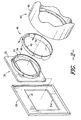
- FIG. 2 is an exploded perspective view of the clothes dryer of FIG. 1, illustrating a bearing assembly in accordance with the present invention.
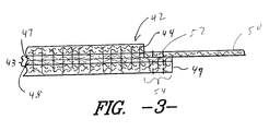
- FIG. 3 is a cut-away side view of a section of the bearing assembly of FIG. 2 .
- the clothes dryer 10 has a box-like cabinet formed from painted sheet metal, as is well known in the art.
- the dryer 10 includes a horizontal top panel 12 with a control console 14 extending along its rear edge.
- the control console allows the user to regulate the operation of the clothes dryer 10 to provide drying of clothes placed within the dryer in a predetermined manner.
- the dyer 10 further includes a pair of vertical side panels 16 and 18 , and a vertical rear panel (not shown).
- a vertical front panel 20 provides an access opening 22 which is normally closed by a door 24 that is hinged along its left edge, as shown, for movement about a vertical axis.
- a door 24 When the door 24 is open as shown in FIG. 1, a user can reach through the access opening 22 and into the interior of the clothes dryer 10 to insert clothing therein or remove clothing therefrom.
- the clothes dryer discussed with regard to FIG. 1 can be seen to include, in addition to the front panel 20 , a drum support panel 30 , a bearing assembly 40 in accordance with the present invention, and a dryer drum 60 that, in operation, rotates on a horizontal axis 70 .
- the front panel 20 provides an inner surface 21 having an inner periphery 21 a which defines, in part, the access opening 22 (see FIG. 1 ).
- the front panel 20 also provides a seat against which the door 24 seals during operation of the dryer 10 .
- a conventional switch (not shown) is provided adjacent the front panel to preclude operation of the dryer without closure of the door 24 against the front panel 20 .
- the drum support panel 30 has a generally planar, plate-like front portion 32 that is fixed by suitable mechanical means to the inner surface 21 of the front panel 20 .
- the drum support panel 30 includes, in addition to the plate-like front portion 32 , a transition ring 33 that is generally annular in shape.
- the transition ring 33 has extending horizontally from its outer circular periphery a circular drum support flange 34 which is inwardly spaced from the plate-like front portion 32 .
- the transition ring 33 extends inwardly from the plate-like portion 32 to support the circular drum support flange 34 at a relatively inwardly displaced position.
- the bearing assembly 40 rotatably supports the front end 62 of the dryer drum 60 , the rear end (not shown) of the drum 60 being supported by conventional means.
- the assembly 40 preferably includes an upper load bearing portion 42 of a interior felt material 43 (FIG.3) adjoined in needled relation to a fibrous surface layer 44 defining a low friction bearing surface 46 (FIG. 2.)
- the interior felt material 43 is of a density and coherency such that that it distributes applied loads and prevents substantial compacting of the load bearing portion 42 due to the load or weight of the front end 62 of the dryer drum 60 . It is contemplated that the interior felt material may be of either a single layer or a multi-layer construction.
- One exemplary multi-layer construction is illustrated in FIG. 3 wherein the interior felt material 43 is made up of a first layer 47 in substantially adjacent relation to the surface layer 44 with at least a second layer 48 extending away from the first layer 47 .
- One contemplated method for manufacture of a multi-layer construction is to incorporate a light weight heat activated fabric adhesive between layers of felted batting and to needle adjacent layers of felted batting across the fabric adhesive followed by heat activation of the adhesive to retain the coordinated structure.
- An exemplary process and resulting multi-layer high density felted materials suitable for use in the present invention is provided in commonly assigned pending U.S. patent application Ser. No. 09/576,720 the contents of which are incorporated herein in their entirety. Of course other production processes may also be utilized if desired.
- the interior felt material 43 is formed by needling long-staple synthetic fibers such as polyester or the like.
- long-staple synthetic fibers such as polyester or the like.
- other materials may include polypropylene, polyamide, acrylic, aramid fibers.
- blends of any of the foregoing may also be used.
- a percentage of natural fibers such as wool or the like may also be added.
- the use of long staple synthetic fibers is particularly preferred to enhance tensile strength and to reduce elongation.
- the interior felt material 43 may include a percentage of fibers including a low melting point constituent such as low melting point polyester fibers or bicomponent polyester fibers having a core of high melting point polyester and a sheath of low melting point polyester.
- Such low melting point constituent fibers may be added directly during blending of the fibers making up the interior felt material 43 and are entangled with the other fibers during needling of the interior felt material.
- the surface layer 44 which contacts the drum 60 is preferably of a nonwoven construction formed by needling or the like although other fibrous constructions including woven or knitted constructions may likewise be utilized if desired.
- the material forming the surface layer 44 is preferably wool or a blend of wool and synthetic fibers such as polyester or the like as described above. The use of a wool constituent in the surface layer 44 is believed to substantially reduce friction with the drum 60 while substantially improving flame retardancy. It is also contemplated that other friction reducing materials may be blended with the fibers forming the surface layer or may be applied after formation.
- an underlying containment layer 49 may be disposed across the side of the interior felted material 43 facing away from the surface layer 44 . However, it is also contemplated that the containment layer 49 may be eliminated if desired. If an underlying containment layer 49 is utilized, the material forming such containment layer is most preferably a wool or wool blend as used in the surface layer 44 . However, it is contemplated that virtually any material having adequate flame retardancy character may be utilized.
- the surface layer 44 and the containment layer 49 are preferably needled in juxtaposed relation to the interior felt material 43 to form a substantially coordinated sandwich structure. That is, during the formation process, fibers from the surface layer 44 and the containment layer are carried into and intermingle with the fibers of the high density felt material.
- an adhesive layer may be disposed between the surface layer 44 and the interior felt material 43 and/or between the containment layer 49 and the interior felt material to further enhance the attachment.
- the surface layer 44 , the interior felt material 43 and the containment layer 49 are each formed separately to have a substantially equivalent density.
- One potentially preferred density range is about 432 to about 576 pounds per cubic yard.
- one or more layers may have substantially higher or lower densities if desired.
- the individual layers are thereafter brought together at a needling station for final needling into a substantially coordinated composite structure. This needling operation may be either a single pass or a multiple pass needling operation.
- the interior felted material 43 is required to be extremely dense and/or extremely thick, it may be desirable to needle batts of material forming the surface layer 44 and containment layer 49 through opposing sides in separate operations.
- the resulting structure is preferably subjected to heat and pressure such as in a flat pressing or calendering operation.
- heat and pressure such as in a flat pressing or calendering operation.
- this process activates any low melting point constituents to further enhance coherency by causing the low melting point constituent to flow and thereby form a bonding matrix within the interior layer.
- This bonding matrix may also promote the ability of the interior layer to carry loads applied during use.
- the pressurized heat activation causes the interior layer to compress thereby increasing the overall density and strength of the interior layer 43 such that the density of the interior layer 43 in the resulting product is slightly higher than the density of the other layers.
- the application of heat and pressure imparts a smooth uniform contact area for contact by the dryer 60 .
- the bearing 40 includes a lower band portion 50 also referred to as a wiper of felted material such as wool or the like extending away from either end of the load bearing portion 42 for disposition in surrounding relation to the drum support flange 34 .
- the lower band portion has a width such that it may be folded upon itself during installation thereby forming a seal at the forward edge of the drum 60 .
- the ends of the lower band portion 50 may be adhered to the load bearing portion by the application of seams 52 such as sewn seams or the like between the lower band portion and an extended lip portion 54 of the load bearing portion 42 . A substantially stable ring-like structure is thereby formed.
Abstract
Description
Claims (13)
Priority Applications (1)
| Application Number | Priority Date | Filing Date | Title |
|---|---|---|---|
| US10/210,295 US6675496B1 (en) | 2002-08-01 | 2002-08-01 | Dryer drum bearing assembly |
Applications Claiming Priority (1)
| Application Number | Priority Date | Filing Date | Title |
|---|---|---|---|
| US10/210,295 US6675496B1 (en) | 2002-08-01 | 2002-08-01 | Dryer drum bearing assembly |
Publications (1)
| Publication Number | Publication Date |
|---|---|
| US6675496B1 true US6675496B1 (en) | 2004-01-13 |
Family
ID=29780265
Family Applications (1)
| Application Number | Title | Priority Date | Filing Date |
|---|---|---|---|
| US10/210,295 Expired - Lifetime US6675496B1 (en) | 2002-08-01 | 2002-08-01 | Dryer drum bearing assembly |
Country Status (1)
| Country | Link |
|---|---|
| US (1) | US6675496B1 (en) |
Cited By (10)
| Publication number | Priority date | Publication date | Assignee | Title |
|---|---|---|---|---|
| US20050017459A1 (en) * | 2003-07-25 | 2005-01-27 | William Cross | Dryer seal |
| US20060196076A1 (en) * | 2005-03-01 | 2006-09-07 | Justice James L Iii | Dryer seal |
| US20070044342A1 (en) * | 2005-08-01 | 2007-03-01 | John Burns | Dryer seal |
| US20070074419A1 (en) * | 2005-09-30 | 2007-04-05 | David Starrett | Multi-layer dryer seal |
| US20080157037A1 (en) * | 2006-12-29 | 2008-07-03 | Warren Stidham | Dryer seal assembly |
| US20090083991A1 (en) * | 2007-09-28 | 2009-04-02 | Mabe Canada Inc. | Clothes dryer bearing gasket support |
| US20130174435A1 (en) * | 2011-11-22 | 2013-07-11 | Owens Corning Intellectual Capital, Llc | Nonwoven material and dryer with nonwoven material |
| US20170044707A1 (en) * | 2015-08-10 | 2017-02-16 | Whirlpool Corporation | Clothes dryer with a drum seal |
| US11293135B2 (en) * | 2018-11-15 | 2022-04-05 | Industrie Ilpea S.P.A. | Seal for a dryer |
| US11821520B2 (en) * | 2017-03-10 | 2023-11-21 | Felters Of South Carolina, Llc | High temperature dryer seals for the rear portion of a dryer and related methods |
Citations (7)
| Publication number | Priority date | Publication date | Assignee | Title |
|---|---|---|---|---|
| US3828445A (en) * | 1973-03-26 | 1974-08-13 | Schlegel Mfg Co | Clothes dryer seal |
| US4669200A (en) * | 1985-11-27 | 1987-06-02 | Whirlpool Corporation | Bulkhead seal for clothes dryer |
| US5216823A (en) | 1992-03-17 | 1993-06-08 | White Consolidated Industries, Inc. | Bearing and seal assembly for clothes dryer drum |
| US5288354A (en) * | 1992-08-26 | 1994-02-22 | Rexnord Corporation | Method of bonding self-lubricating fibers to an external surface of a substratum |
| US5363569A (en) | 1993-03-11 | 1994-11-15 | White Consolidated Industries, Inc. | Bearing and seal assembly for clothes dryer drum |
| US5548908A (en) * | 1995-06-13 | 1996-08-27 | White Consolidated Industries, Inc. | Bulkhead and expanded drum without rollers |
| US6398415B1 (en) * | 1999-07-09 | 2002-06-04 | Asmo Co., Ltd. | Bearing device using felt member and method of manufacturing same |
-
2002
- 2002-08-01 US US10/210,295 patent/US6675496B1/en not_active Expired - Lifetime
Patent Citations (7)
| Publication number | Priority date | Publication date | Assignee | Title |
|---|---|---|---|---|
| US3828445A (en) * | 1973-03-26 | 1974-08-13 | Schlegel Mfg Co | Clothes dryer seal |
| US4669200A (en) * | 1985-11-27 | 1987-06-02 | Whirlpool Corporation | Bulkhead seal for clothes dryer |
| US5216823A (en) | 1992-03-17 | 1993-06-08 | White Consolidated Industries, Inc. | Bearing and seal assembly for clothes dryer drum |
| US5288354A (en) * | 1992-08-26 | 1994-02-22 | Rexnord Corporation | Method of bonding self-lubricating fibers to an external surface of a substratum |
| US5363569A (en) | 1993-03-11 | 1994-11-15 | White Consolidated Industries, Inc. | Bearing and seal assembly for clothes dryer drum |
| US5548908A (en) * | 1995-06-13 | 1996-08-27 | White Consolidated Industries, Inc. | Bulkhead and expanded drum without rollers |
| US6398415B1 (en) * | 1999-07-09 | 2002-06-04 | Asmo Co., Ltd. | Bearing device using felt member and method of manufacturing same |
Cited By (17)
| Publication number | Priority date | Publication date | Assignee | Title |
|---|---|---|---|---|
| US20050017459A1 (en) * | 2003-07-25 | 2005-01-27 | William Cross | Dryer seal |
| US7007955B2 (en) * | 2003-07-25 | 2006-03-07 | The Felters Group | Dryer seal |
| US20060145430A1 (en) * | 2003-07-25 | 2006-07-06 | The Felters Group | Dryer seal |
| US20060196076A1 (en) * | 2005-03-01 | 2006-09-07 | Justice James L Iii | Dryer seal |
| WO2006093888A2 (en) * | 2005-03-01 | 2006-09-08 | The Felters Company | Dryer seal |
| WO2006093888A3 (en) * | 2005-03-01 | 2007-04-26 | Felters Company | Dryer seal |
| US20070044342A1 (en) * | 2005-08-01 | 2007-03-01 | John Burns | Dryer seal |
| US20070074419A1 (en) * | 2005-09-30 | 2007-04-05 | David Starrett | Multi-layer dryer seal |
| US20080157037A1 (en) * | 2006-12-29 | 2008-07-03 | Warren Stidham | Dryer seal assembly |
| US20090083991A1 (en) * | 2007-09-28 | 2009-04-02 | Mabe Canada Inc. | Clothes dryer bearing gasket support |
| US8028439B2 (en) | 2007-09-28 | 2011-10-04 | Mabe Canada Inc. | Clothes dryer bearing gasket support |
| US20130174435A1 (en) * | 2011-11-22 | 2013-07-11 | Owens Corning Intellectual Capital, Llc | Nonwoven material and dryer with nonwoven material |
| US20170044707A1 (en) * | 2015-08-10 | 2017-02-16 | Whirlpool Corporation | Clothes dryer with a drum seal |
| US9580856B1 (en) * | 2015-08-10 | 2017-02-28 | Whirlpool Corporation | Clothes dryer with a drum seal |
| US10066336B2 (en) | 2015-08-10 | 2018-09-04 | Whirlpool Corporation | Clothes dryer with a drum seal |
| US11821520B2 (en) * | 2017-03-10 | 2023-11-21 | Felters Of South Carolina, Llc | High temperature dryer seals for the rear portion of a dryer and related methods |
| US11293135B2 (en) * | 2018-11-15 | 2022-04-05 | Industrie Ilpea S.P.A. | Seal for a dryer |
Similar Documents
| Publication | Publication Date | Title |
|---|---|---|
| US6675496B1 (en) | Dryer drum bearing assembly | |
| US7454817B2 (en) | Heat and flame shield | |
| US4522876A (en) | Integral textile composite fabric | |
| US7229938B2 (en) | Heat and flame shield | |
| US7709405B2 (en) | Non-woven composite | |
| US5770530A (en) | Protective layer, particularly anti-vandalism protective layer | |
| EP0763418B1 (en) | Method for producing a multilayered web for upholstery cover material for vehicles | |
| US5173355A (en) | Spun-bonded fabric consolidated by a hot-melt binder | |
| EP0896645A2 (en) | Durable spunlaced fabric structures | |
| US20070044342A1 (en) | Dryer seal | |
| JP4361202B2 (en) | Sound-absorbing material including meltblown nonwoven fabric | |
| US5236770A (en) | Nonwoven laminate | |
| US20030104749A1 (en) | Sound absorbing material | |
| JPH07268782A (en) | Improved membrane for roof meterial and its preparation | |
| USRE33023E (en) | Integral textile composite fabric | |
| KR20010031798A (en) | Durable, Absorbent Spunlaced Fabric Structures | |
| JPH08323903A (en) | Interior material for car and production thereof | |
| TWI241368B (en) | Insulating and footwear system | |
| CN213972981U (en) | Functional thermal bonding non-woven fabric | |
| US11738535B2 (en) | Metallized breathable composite textile | |
| US5656354A (en) | Root-resistant base layer | |
| US20040253891A1 (en) | Composite structure for protective garment | |
| GB2246097A (en) | Composite flame blocking fabric | |
| JPH07227488A (en) | Surface material for interior decoration of automobile | |
| JPH10273860A (en) | Needle-punched carpet |
Legal Events
| Date | Code | Title | Description |
|---|---|---|---|
| AS | Assignment |
Owner name: FELTERS COMPANY, THE, SOUTH CAROLINA Free format text: ASSIGNMENT OF ASSIGNORS INTEREST;ASSIGNORS:MOON, JOSEPH;BURNS, JOHN J.;OWENS JR., JERRY W.;REEL/FRAME:013444/0298 Effective date: 20021008 |
|
| STCF | Information on status: patent grant |
Free format text: PATENTED CASE |
|
| AS | Assignment |
Owner name: GENERAL ELECTRIC CAPITAL CORPORATION, AS AGENT, IL Free format text: SECURITY AGREEMENT;ASSIGNOR:THE FELTERS COMPANY;REEL/FRAME:017858/0867 Effective date: 20060629 |
|
| FPAY | Fee payment |
Year of fee payment: 4 |
|
| FEPP | Fee payment procedure |
Free format text: PAYOR NUMBER ASSIGNED (ORIGINAL EVENT CODE: ASPN); ENTITY STATUS OF PATENT OWNER: SMALL ENTITY |
|
| AS | Assignment |
Owner name: FELTERS OF SOUTH CAROLINA, LLC,SOUTH CAROLINA Free format text: ASSIGNMENT OF ASSIGNORS INTEREST;ASSIGNOR:THE FELTERS COMPANY;REEL/FRAME:024006/0695 Effective date: 20091221 |
|
| FEPP | Fee payment procedure |
Free format text: PAYOR NUMBER ASSIGNED (ORIGINAL EVENT CODE: ASPN); ENTITY STATUS OF PATENT OWNER: SMALL ENTITY Free format text: PAYER NUMBER DE-ASSIGNED (ORIGINAL EVENT CODE: RMPN); ENTITY STATUS OF PATENT OWNER: SMALL ENTITY |
|
| REMI | Maintenance fee reminder mailed | ||
| FPAY | Fee payment |
Year of fee payment: 8 |
|
| SULP | Surcharge for late payment |
Year of fee payment: 7 |
|
| FPAY | Fee payment |
Year of fee payment: 12 |
|
| SULP | Surcharge for late payment |
Year of fee payment: 11 |