EP3130185B1 - Bestimmung der position einer drahtlosen vorrichtung mit entfernten funkkopfvorrichtungen - Google Patents
Bestimmung der position einer drahtlosen vorrichtung mit entfernten funkkopfvorrichtungen Download PDFInfo
- Publication number
- EP3130185B1 EP3130185B1 EP14719387.4A EP14719387A EP3130185B1 EP 3130185 B1 EP3130185 B1 EP 3130185B1 EP 14719387 A EP14719387 A EP 14719387A EP 3130185 B1 EP3130185 B1 EP 3130185B1
- Authority
- EP
- European Patent Office
- Prior art keywords
- radio head
- remote radio
- frequency
- manipulation
- head devices
- Prior art date
- Legal status (The legal status is an assumption and is not a legal conclusion. Google has not performed a legal analysis and makes no representation as to the accuracy of the status listed.)
- Active
Links
Images

Classifications
-
- H—ELECTRICITY
- H04—ELECTRIC COMMUNICATION TECHNIQUE
- H04W—WIRELESS COMMUNICATION NETWORKS
- H04W4/00—Services specially adapted for wireless communication networks; Facilities therefor
- H04W4/02—Services making use of location information
- H04W4/025—Services making use of location information using location based information parameters
- H04W4/027—Services making use of location information using location based information parameters using movement velocity, acceleration information
-
- H—ELECTRICITY
- H04—ELECTRIC COMMUNICATION TECHNIQUE
- H04W—WIRELESS COMMUNICATION NETWORKS
- H04W64/00—Locating users or terminals or network equipment for network management purposes, e.g. mobility management
-
- H—ELECTRICITY
- H04—ELECTRIC COMMUNICATION TECHNIQUE
- H04W—WIRELESS COMMUNICATION NETWORKS
- H04W88/00—Devices specially adapted for wireless communication networks, e.g. terminals, base stations or access point devices
- H04W88/08—Access point devices
- H04W88/085—Access point devices with remote components
Definitions
- the invention relates to a method, network node, computer program, and computer program product for determining a position of a wireless device using remote radio head devices.
- One solution to this problem is to use remote radio head devices, where several remote radio head devices connected to the same radio base station share the same cell. In this way, a single radio base station can provide coverage in different parts of the building by placing the remote radio head devices appropriately. Moreover, the wireless device can move between the coverage of different remote radio head devices while staying within the same cell, thus avoiding causing handovers.
- a method for assisting the determining of a position of a wireless device the method being performed in a network node connected to a plurality of remote radio head devices via a combiner.
- the method comprises the steps of: receiving an uplink signal via the combiner; comparing a carrier frequency of the uplink signal with a set of manipulation schemes for a carrier frequency of uplink signals, wherein the manipulation schemes are different for at least some of the plurality of remote radio head devices; and providing a proximity indication that the position of the wireless device is in the vicinity of a remote radio head device the frequency manipulation scheme of which best matches the uplink signal.
- a position of the wireless device can at least be determined to be close to a one or more remote radio head devices. This is a significant improvement over the prior art, and can, depending on the spacing of the remote radio head devices with different manipulation schemes, allow compliance with increased location accuracy requirements. Moreover, this method allows the location to be determined regardless whether the remote radio head devices are deployed inside a building or outside. Furthermore, the remote radio heads may already perform a frequency conversion of the signal, whereby it is relatively easy to deploy this solution.
- the manipulation schemes may be different for each one of the plurality of remote radio head devices. In this way, a more accurate positioning is enabled, allowing positioning in the vicinity of a particular remote radio head device.
- the manipulation schemes may comprise a different fixed frequency offset for each one of the remote radio head devices. This is a pragmatic and relatively uncomplicated solution which in many cases is sufficient. No dynamic control is then required for the manipulation scheme.
- the manipulation schemes may comprise a different modulation using frequency shift keying for each one of the remote radio head devices. In this way, a greater number of different manipulation schemes can be deployed in a given frequency range.
- the manipulation schemes may comprise different magnitudes of alternating frequency offsets for each one of the remote radio head devices and the comparing may comprise comparing a difference between alternating frequency offsets of the carrier frequency with the difference between the alternating offsets for each one of the remote radio head devices.
- the frequency manipulation scheme may comprise a different frequency hopping scheme for each one of the remote radio head devices.
- the step of providing a proximity indication may comprise providing an indication of proximity of the wireless device to a plurality of remote radio head devices by considering contributions from of a plurality of manipulation schemes to the uplink signal. This allows an even greater accuracy of the determination of position.
- the method may further comprise the step of: providing a velocity indication, indicating a velocity of the wireless device based on a frequency offset of the uplink signal compared to the manipulation scheme for the radio head device whose frequency manipulation scheme best matches the uplink signal.
- the manipulation scheme may comprise different frequency manipulation for different diversity paths for each remote radio head device. This gives another dimension to use for differentiation, increasing the number of different manipulation schemes can be deployed in a given frequency range.
- the method may further comprise the step of: configuring each one of the plurality of remote radio head devices with a different manipulation scheme.
- the method may further comprise the step of: determining a position of the wireless device based on the proximity indication.
- the position determination can be determined within the network node.
- a network node for assisting the determining of a position of a wireless device.
- the network node is connectable to a plurality of remote radio head devices via a combiner.
- the network node comprises: a processor; and a memory storing instructions that, when executed by the processor, causes the network node to: receive an uplink signal via the combiner; compare a carrier frequency of the uplink signal with a set of manipulation scheme for a carrier frequency of uplink signals, wherein the manipulation schemes are different for at least some of the plurality of remote radio head devices; and provide a proximity indication that the position of the wireless device is in the vicinity of a remote radio head device the frequency manipulation scheme of which best matches the uplink signal.
- the instructions to compare may comprise instructions that, when executed by the processor, causes the network node to consider that the manipulation schemes are different for each one of the plurality of remote radio head devices.
- the instructions to compare may comprise instructions that, when executed by the processor, causes the network node to consider manipulation schemes comprising a different fixed frequency offset for each one of the remote radio head devices.
- the instructions to compare may comprise instructions that, when executed by the processor, causes the network node to consider manipulation schemes comprising a different modulation using frequency shift keying for each one of the remote radio head devices.
- the instructions to compare may comprise instructions that, when executed by the processor, causes the network node to consider manipulation schemes comprising different magnitudes of alternating frequency offsets for each one of the remote radio head devices and to perform the comparing by comparing a difference between alternating frequency offsets of the carrier frequency with the difference between the alternating offsets for each one of the remote radio head devices.
- the instructions to compare may comprise instructions that, when executed by the processor, causes the network node to consider manipulation schemes comprising a different frequency hopping scheme for each one of the remote radio head devices.
- the instructions to provide a proximity indication may comprise instructions that, when executed by the processor, causes the network node to provide an indication of proximity of the wireless device to a plurality of remote radio head devices by considering contributions from of a plurality of manipulation schemes to the uplink signal.
- the network node may further comprise instructions that, when executed by the processor, causes the network node to provide a velocity indication, indicating a velocity of the wireless device based on a frequency offset of the uplink signal compared to the manipulation scheme for the radio head device whose frequency manipulation scheme best matches the uplink signal.
- the instructions to compare may comprise instructions that, when executed by the processor, causes the network node to consider manipulation schemes comprising different frequency manipulations for different diversity paths for each remote radio head device.
- the network node may further comprise instructions that, when executed by the processor, causes the network node to configure each one of the plurality of remote radio head devices with a different manipulation scheme.
- the network node may further comprise instructions that, when executed by the processor, causes the network node to determine a position of the wireless device based on the proximity indication.
- a network node comprising: means for receiving an uplink signal via the combiner connected to a plurality of remote radio head devices; means for comparing a carrier frequency of the uplink signal with a set of manipulation scheme for a carrier frequency of uplink signals, wherein the manipulation schemes are different for at least some of the plurality of remote radio head devices; and means for providing a proximity indication that the position of the wireless device to be in the vicinity of a remote radio head device the frequency manipulation scheme of which best matches the uplink signal.
- the manipulation schemes may be different for each one of the plurality of remote radio head devices.
- the manipulation schemes may comprise a different fixed frequency offset for each one of the remote radio head devices.
- the manipulation schemes may comprise a different modulation using frequency shift keying for each one of the remote radio head devices.
- the manipulation schemes may comprise different magnitudes of alternating frequency offsets for each one of the remote radio head devices and the comparing may comprise comparing a difference between alternating frequency offsets of the carrier frequency with the difference between the alternating offsets for each one of the remote radio head devices.
- the frequency manipulation scheme may comprise a different frequency hopping scheme for each one of the remote radio head devices.
- the means for providing a proximity indication may comprise means for providing an indication of proximity of the wireless device to a plurality of remote radio head devices by considering contributions from of a plurality of manipulation schemes to the uplink signal.
- the network node may further comprise means for providing a velocity indication, indicating a velocity of the wireless device based on a frequency offset of the uplink signal compared to the manipulation scheme for the radio head device whose frequency manipulation scheme best matches the uplink signal.
- the manipulation scheme may comprise different frequency manipulation for different diversity paths for each remote radio head device.
- the network node may further comprise means for configuring each one of the plurality of remote radio head devices with a different manipulation scheme.
- the network node may further comprise means for determining a position of the wireless device based on the proximity indication.
- a computer program for a network node to assist the determining of a position of a wireless device, the network node being connectable to a plurality of remote radio head devices via a combiner.
- the computer program comprises computer program code which, when run on the network node causes the network node to: receive an uplink signal via the combine; compare a carrier frequency of the uplink signal with a set of manipulation scheme for a carrier frequency of uplink signals, wherein the manipulation schemes are different for at least some of the plurality of remote radio head devices; and provide a proximity indication that the position of the wireless device to be in the vicinity of a remote radio head device the frequency manipulation scheme of which best matches the uplink signal.
- a computer program product comprising a computer program according to the fourth aspect and a computer readable means on which the computer program is stored.
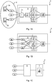
- Figs 1A-C are schematic architecture diagrams illustrating a wireless communication networks 3 being environments where embodiments presented herein can be applied.
- the wireless communication network 3 comprises a number of remote radio head devices 1a-c for installation in locations where traditional deployment with antennas being co-located with the radio base stations is not ideal.
- the wireless communication network 3 can be installed indoors, such as in an office, shopping centre, train station or airport.
- LTE Long Term Evolution
- any applicable communication standard may be used, such as any one or a combination of LTE-SAE (Long Term Evolution - System Architecture Evolution), W-CDMA (Wideband Code Division Multiplex), EDGE (Enhanced Data Rates for GSM (Global System for Mobile communication) Evolution), GPRS (General Packet Radio Service), CDMA2000 (Code Division Multiple Access 2000), or any other current or future wireless network, such as LTE-Advanced, as long as the principles described hereinafter are applicable.
- LTE-SAE Long Term Evolution - System Architecture Evolution
- W-CDMA Wideband Code Division Multiplex
- EDGE Enhanced Data Rates for GSM (Global System for Mobile communication) Evolution
- GPRS General Packet Radio Service
- CDMA2000 Code Division Multiple Access 2000
- any other current or future wireless network such as LTE-Advanced, as long as the principles described hereinafter are applicable.
- a radio base station 7 here comprises a baseband module 18 and an intermediate radio unit (IRU) 5, also known as indoor radio unit when deployed indoors.
- the IRU 5 is in turn connected to, and is a link for, a number (in this example three) remote radio head devices 1a-c via respective cables.
- the radio base station 7 is a link for uplink and downlink communication for the remote radio head devices connected to the IRU.
- the remote radio head devices 1a-c connected to the IRU 5 are part of a single cell 6 and thus share a cell identifier. Antennas do not need to be included in this embodiment of the radio base station 7 or the IRU 5, as the remote radio head devices 1a-c provide the antennas for the wireless link to one or more wireless devices 2a-b.
- the wireless link provided by the remote radio head devices 1a-c includes both downlink (DL) communication to the wireless devices 2a-b and uplink (UL) communication from the wireless devices 2a-b.
- wireless device is also known as mobile communication terminal, user equipment (UE), station (STA), mobile terminal, user terminal, user agent, machine-to-machine devices etc., and can be, for example, what today is commonly known as a mobile phone or a tablet/laptop with wireless connectivity or fixed mounted terminal.
- the data is transmitted and received over the air at a specific radio frequency- either the same for transmission and reception or on separate frequencies. This is often called the radio frequency (RF) or the carrier frequency.
- RF radio frequency
- IF Intermediate Frequency
- the remote radio head devices 1a-c downconvert a received (uplink) signal to IF and send it over its cable to the IRU 5.
- the received IF signals are combined in a combiner 15 and fed to an interface circuitry 4.
- the interface circuitry 4 extracts the received IF signal from the interface and forwards it to the RX (reception) back-end 11.
- the RX backend 11 comprises an analogue to digital (A/D) converter which samples the signal on IF and converts to a digital signal.
- the RX back-end 11 first downconverts the received signals from IF to an analogue BB (baseband) signal which is further filtered and converter to a digital signal in an analogue to digital converter.
- the RX back-end 11 sends the combined received signals in digital form to the baseband module 18 for further processing such as demodulation, decoding, etc. as known in the art per se.
- the remote radio head devices 1a-c are also powered over the respective cables.
- the process works in reverse to the uplink.
- the baseband module 18 sends a digital BB signal for transmission to a TX (transmission) back-end 10 of the IRU 5.
- the TX back-end 10 converts the digital BB signal to an analogue signal in IF directly in a digital to analogue (D/A) converter.
- the TX back-end 10 pulse first shapes the digital BB signal to an analogue transmission signal and upconverts the transmission signal to IF in the analogue domain.
- the transmission signal in IF is then inserted onto the interface by the interface circuitry 4, and provided to the combiner 15 which also functions as a splitter, providing the same transmission signal in IF to all connected remote radio head devices 1a-c over the respective cables.
- the remote radio head devices 1a-c then upconvert the IF signal to RF and transmit the RF signal over the air to the wireless devices 2a-b.
- the remote radio head devices 1a-c convert from IF to RF for downlink transmission and from RF to IF for uplink reception. Conversely, the IRU converts from digital BB to IF for downlink transmission and from IF to digital BB for uplink reception.
- control link between a processor 12 in the IRU 5 and each remote radio head device 1a-c.
- This control link can be used e.g. to set the RF frequency used for downconversion and upconversion in the remote radio head devices 1a-c.
- the transmission and reception is under the control of the MAC (Media Access Control) scheduler in the baseband module 18.
- the MAC scheduler informs what transmissions should be made and informs, via the downlink signaling, the wireless devices when to transmit and on which frequency and power.
- Fig 1A shows the baseband module 18 connected to one IRU 5
- each baseband module 18 can be connected to several IRUs.
- Each IRU may have its own cell or several IRUs may share a single cell.
- Fig 1A shows three remote radio head devices 1a-c, there may be fewer or more remote radio head devices connected to each IRU 5.
- Fig 1B The embodiment shown in Fig 1B is similar to the embodiment of Fig 1A , and only differences to the embodiment of Fig 1A will be described.
- interface circuitry 4a-c there are several instances of interface circuitry 4a-c, one for each remote radio head device. Transmission signals are sent in IF from the transmission back-end 10 to each one of the instances of interface circuitry 4a-c, either directly or via a splitter (not shown). Analogously, control signals are sent between the processor 12 and each one of the interface circuitry 4a-c, either directly or via a splitter (not shown). Received signals are sent in IF from the respective interface circuitry 4a-c to a combiner 15' which, may here be a pure combiner without splitting functionality.
- the TX back-end 10 may send the transmission signal using different IF frequencies to the different instances of interface circuitry 4a-c, and the RX back-end 11 downconverts from different IF frequencies for the different instances of interface circuitry 4a-c.
- Fig 1C is a schematic architecture diagram illustrating an alternative embodiment in terms of IRU and radio base station.
- the IRU 5 is separate, but connected to, the radio base station 7.
- the IRU 5 itself can be implemented e.g. as shown in Fig 1A or Fig 1B .
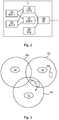
- Fig 2 is a schematic architecture diagram illustrating components of an embodiment of a remote radio head device of Figs 1-C , here represented by a single remote radio head device 1.
- the remote radio head device comprises an interface circuitry 39, a transmission front-end 36, a reception front-end 37, a digital unit 38, a first antenna device 25 and a second antenna device 26. It is to be noted that there may be more than two antennas, such as four, six, eight, etc. Furthermore, there may also be only one antenna, if MIMO (Multiple Input Multiple Output) is not employed.
- MIMO Multiple Input Multiple Output
- the RX Front End 37 downconverts received signals in RF to IF for transfer over the cable to the IRU 5. Moreover, the TX Front End 36 upconverts transmission signals from IF, as received over the cable from the IRU 5 to RF for transmission to wireless devices.
- the first antenna device 25 and second antenna device 26 maybe provided with separate streams for MIMO transmission and/or reception.
- the baseband module can provide a first MIMO stream for transmission on the first antenna device 25 and a second MIMO stream for transmission on the second antenna device 26.
- Each one of the first and second antenna devices 25, 26 may comprise one or more antenna elements.
- each antenna device 25, 26 can comprise one or more antenna elements in a first polarisation and one or more antenna elements in a second polarisation to achieve an additional dimension of orthogonality. The two polarisations maybe controlled separately.
- the antenna devices 25, 26 may also comprise appropriate filters to filter out unwanted signals.
- remote radio head device 1 comprising two antenna devices, there may be more antenna devices, e.g. four, eight, sixteen, etc.
- the interface circuitry 39 inserts and extracts (multiplexes and demultiplexes) the transmission IF signal, the received IF signal and the control signal onto/from the cable.
- the interface circuitry 39 may use different frequency bands for uplink signals, downlink signals and control signals to thereby multiplex all of these on a single cable.
- a digital unit 38 communicates with the processor 12 of the IRU.
- the digital unit 38 may be used to receive commands from the processor 12 to alter frequencies used by the TX Front End 36 and RX Front End 37 for upconversion and/or downconversion.
- the digital unit 38 can be implemented using software instructions such as a computer program executed by a processor and/or using only hardware, such as application specific integrated circuits, field programmable gate arrays, discrete logical components, etc.
- the remote radio head device is connected to the radio base station via digital transmissions (not shown).
- the remote radio head device performs analogue to digital conversion, and vice versa, as well as downconversion/upconversion of the analogue signals from/to RF for reception and transmission from/to the wireless devices.
- the digital signal between IRU and radio head maybe CPRI signal.
- the radio head performs the conversion between CPRI signal and RF signal.
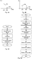
- Fig 3 is a schematic topological diagram illustrating cell coverage of the three remote radio head devices 1a-c of Figs 1A-C according to one embodiment.
- the first radio head device 1a provides coverage in a first coverage area 6a.
- the second radio head device 1b provides coverage in a second coverage area 6b.
- the third radio head device 1c provides coverage in a third coverage area 6c. There is here some overlap between the coverage areas.
- a first wireless device 2a is located in the first coverage area 6a.
- the first wireless device is essentially stationary.
- a second wireless device 2b is located in the second coverage area 6b.
- the second wireless device is moving, essentially in a direction from the second remote radio head device 1b towards the third remote radio head device 1c.
- Figs 4A-B are schematic graphs illustrating the use of frequency components to indicate position and velocity of a wireless device of Fig 3 according to one embodiment.
- the horizontal axis represents a frequency offset in Hertz from an expected carrier frequency for an uplink signal.
- the horizontal axis represents a magnitude of any frequency components of the uplink signal after combination (i.e. after the combiner 15, 15' of Fig 1A or Fig 1B .
- the graphs of Figs 4A-B will now be explained with additional reference to Fig 3 .
- All remote radio head device 1a-c apply a frequency manipulation scheme on any received uplink signal prior to forwarding the signals to a central node in the network. As explained further below, this assists in determining positions of wireless devices.
- the manipulation schemes in the remote radio head devices are different fixed frequency offsets, achieved in the reception front-end 37 where a frequency shift is applied anyway.
- the fixed frequency offset then implies that a slightly different frequency is used for the downconversion of the received RF signal to IF.
- the fixed frequency offset is 100 Hz
- the fixed frequency offset is 200 Hz
- the fixed frequency offset is 300 Hz.
- Fig 4A components of the uplink signal are shown for the first wireless device 2a.
- Fig 4B components of the uplink signal are shown for the second wireless device 2b.
- first frequency component 19a slightly below 200 Hz and a second frequency component 19b slightly above 300 Hz.
- the magnitude of the two frequency components 19a-b are about the same and both significant, reflecting the position of the second wireless device 2b in between the second remote radio head device 1b and the third remote radio head device 1c.
- the downshift of the first frequency component 19a relative to 200 Hz indicates a movement away from the second remote radio head device 1b and the upshift of the second frequency component 19b relative to 300 Hz indicates a movement towards from the third remote radio head device 1b. As explained below, this can be used to assist in determination of velocity of the second wireless device 2b.
- Figs 5A-B are flow charts illustrating methods performed in a network node of Fig 1 for assisting the determining of a position of a wireless device.
- the network node can be the radio base station 7 or the IRU 5 of Figs 1A-C .
- the network node is connected to a plurality of remote radio head devices as described above.
- the method can e.g. be started when a request for a position of a specific wireless device is received by the network node.
- the method can be performed in parallel for several wireless devices if needed.
- a receive uplink signal step 40 an uplink signal is received via the combiner.
- the uplink signals is thus a combination of uplink signals received by a plurality of remote radio head devices connected to the network node via the combiner.
- a compare step 42 the carrier frequency of the uplink signal is compared with a set of manipulation scheme for a carrier frequency of uplink signals, wherein the manipulation schemes are different for at least some of the plurality of remote radio head devices.
- the differentiation occurs between remote radio head devices having different manipulation schemes. Hence, there could be two (or more remote radio head devices) sharing a single manipulation scheme. This is particularly useful if the remote radio head devices are closer to each other than the desired granularity of positioning. In this way, the number of different manipulation schemes that are required is reduced.
- the manipulation schemes are different for each one of the plurality of remote radio head devices. In this way, a position can be determined to be in the proximity of a specific remote radio head device, enabling an increased accuracy of positioning.
- the manipulation schemes comprise a different fixed frequency offset for each one of the remote radio head devices.
- the wireless device With typical indoor velocities peaking somewhere around 11 m/s (corresponds to about 40 km/h), the wireless device introduces a maximum frequency offset due to Doppler shift of around ⁇ 150 Hz. Extreme frequency offset scenarios such as high speed train cases with speeds at 350 km/h mentioned, pushing frequency offset at 1.5 kHz or more, are assumed not to be applicable for indoor radio systems.
- the frequency inaccuracy in the eNodeB in LTE is specified to be less than 0.05 ppm which corresponds to ⁇ 100Hz at a carrier frequency of 2 GHz.
- the local oscillator of the wireless device in LTE is specified in 3GPP 25.101 version 12.3.0 to have a frequency inaccuracy of less than 100 ppb (parts per billion) which corresponds to ⁇ 200 Hz at a carrier frequency of 2 GHz.
- the accuracy of practical wireless devices in LTE is typically 10 ppb, which corresponds to ⁇ 20 Hz at the 2 GHz band.
- the offset frequency offset is selected to be large enough to be detectable, but small enough not to significantly deteriorate signal quality (SNR) and Doppler shift estimation reliability.
- any frequency shifts of the manipulation is kept within +-750 Hz of the carrier frequency.
- WCDMA Wideband Code Division Multiple Access
- One example of how to configure frequency offsets for eight different remote radio heads could hen be to use a set of the following fixed frequency offsets: +200 Hz, +300 Hz, +400 Hz, +500 Hz and -200 Hz, -300 Hz, -400 Hz, and - 500 Hz. With higher accuracy in the frequency offset estimation, more remote radio head devices can be provided within -500 Hz and +500Hz.
- the manipulation schemes comprise a different modulation using frequency shift keying for each one of the remote radio head devices.
- the frequency shift in time it is possible to distinguish between more remote radio head devices within a given frequency range. Also varying frequency shifts in time can be used to mitigate the impact of the clock inaccuracies in the wireless device.
- the manipulation schemes can comprise different magnitudes of alternating frequency offsets for each one of the remote radio head devices, e.g. +/-200 Hz for a first remote radio head device and +/-300 Hz for a second remote radio head device.
- the comparing then comprises comparing a difference between alternating frequency offsets over time of the carrier frequency with the difference between the alternating offsets for each one of the remote radio head devices. For instance, if the difference between the alternating frequency offsets of the carrier frequency is 400 Hz, then the uplink signal matches the first remote radio head device, while if the difference between the alternating frequency offsets of the carrier frequency is 600 Hz, then the uplink signal matches the second remote radio head device.
- any clock inaccuracies in the remote radio head devices are compensated for. Even effects from Doppler shifts from movement can be reduced or even eliminated using this embodiment.
- the frequency manipulation scheme comprises a different frequency hopping scheme for each one of the remote radio head devices.
- the hopping sequences applied to remote radio heads should be orthogonal.
- the manipulation scheme comprises different frequency manipulation for different diversity paths for each remote radio head device.
- Diversity paths are e.g. different MIMO (Multiple Input Multiple Output) streams.
- MIMO Multiple Input Multiple Output
- a frequency shift of +100 Hz may be applied to uplink signals on a first diversity path for a first remote radio head device and a frequency shift of +100 Hz may be applied to uplink signals on a second diversity path for a second remote radio head device.
- the frequency shifts are identical, since these are applied to different diversity paths, these are distinguishable from each other. This increases the ability to distinguish between remote radio head devices within a certain frequency range.
- a proximity indication is provided, where the proximity indication indicates that the position of the wireless device is in the vicinity of a remote radio head device the frequency manipulation scheme of which best matches the uplink signal.
- the proximity indication is provided to a positioning node which uses the proximity indication to determine the position of the wireless device.
- the positioning node can be the network node or it can be a separate node.
- the positioning node determines the position of the wireless device, e.g. by looking up the position of the indicated remote radio head device in a database mapping remote radio head devices to positions, e.g. in the form of latitude/longitude coordinated, optionally with an elevation value.
- the proximity indication would then be an indication of the second remote radio head device 1b.
- this comprises providing an indication of proximity of the wireless device to a plurality of remote radio head devices by considering contributions from of a plurality of manipulation schemes to the uplink signal.
- the proximity indication can comprise an indication of magnitude (see e.g. 19a and 19b of Figs 4A-B ) associated with each one of a plurality of remote radio head devices.
- the proximity indication could then include a magnitude indication of the first, second and third remote radio head devices 1a-c. This allows, e.g. by using triangulation, the position of the wireless device to be determined with even greater accuracy.
- Fig 5B is a flow chart illustrating a method similar to the method illustrated in Fig 5A . Only new steps or steps which are modified compared to the method illustrated in Fig 5A will be described below.
- each one of the plurality of remote radio head devices connected to the network node are configured with a different manipulation scheme, in accordance with any of the manipulation schemes described above.
- the frequency manipulation can be turned on dynamically when a position is to be determined, whereby the frequency manipulation does not need to be applied when position determination is not active.
- a velocity indication is provided.
- the velocity indication indicates a velocity of the wireless device based on a frequency offset of the uplink signal compared to the manipulation scheme for the radio head device whose frequency manipulation scheme best matches the uplink signal, as described with reference to Fig 4B above.
- the velocity indication can be calculated by considering the measured frequency offset FO relative the introduced frequency offset FO k of the remote radio head device k .
- multiple relative velocities can be estimated.
- the multiple relative velocities can then be accumulated (using vector addition of vectors determined using the position of the wireless device and the position of each remote radio head device) to yield an estimate of the absolute velocity of the wireless device.
- a time series of parameter estimates can be considered when estimating the position of the wireless device.
- the relative velocity may then be considered to assess how the wireless device can be assumed to have travelled from one time instant to another.
- velocity components with regard to multiple remote radio head devices can be utilized.
- a motion model can be considered to model the wireless device mobility pattern.
- One common example of such a linear system due to mobility of an object is a model based on random acceleration. This means that the acceleration in the x and y direction is not correlated between time steps and has a zero-mean Gaussian noise with variance ⁇ a 2 .
- the model also includes measurement noise assumptions, such that the measurement errors are uncorrelated between time steps, with a zero-mean Gaussian noise with covariance matrix R t .
- the measurement equation is nonlinear in the states ( h(x t ) ) .
- This can be handled by estimating a linear model locally around the current state estimate.
- x x t
- the Kalman filter can be seen as a filter in two phases, first a time update and then a measurement update
- the intermediate variables S, K and P of the Kalman filter can be seen as by-products, but for example P t
- the initial position assumption (first two elements of x ⁇ 0
- 0 could be set with respect to those crude estimates, for example reflecting the cell radius as well as how likely that the mobile is stationary.
- the position of the wireless device is determined based on the proximity indication. If this step is not performed in the network node, it can be performed in another node.
- the velocity of the wireless device is determined based on the velocity indication, when present. If this step is not performed in the network node, it can be performed in another node.
- any previously configured manipulation scheme in the configure step 39 can be removed. In this way, the manipulation schemes are only applied when needed.
- Fig 6 is a schematic diagram showing some components of the radio base station 7 of Figs 1A-C .
- a processor 60 is provided using any combination of one or more of a suitable central processing unit (CPU), multiprocessor, microcontroller, digital signal processor (DSP), application specific integrated circuit (ASIC) etc., capable of executing software instructions 66 stored in a memory 64, which can thus be a computer program product.
- the processor 60 can be configured to execute the methods described with reference to Figs 5A-B above.
- the memory 64 can be any combination of read and write memory (RAM) and read only memory (ROM).
- the memory 64 also comprises persistent storage, which, for example, can be any single one or combination of magnetic memory, optical memory, solid state memory or even remotely mounted memory.
- a data memory 65 can be any combination of read and write memory (RAM) and read only memory (ROM).
- the data memory 65 may also comprise persistent storage, which, for example, can be any single one or combination of magnetic memory, optical memory, solid state memory or even remotely mounted memory.
- the data memory 65 can e.g. store measurement reports received from wireless devices to be used for positioning of the wireless device as described above.
- the radio base station 7 further comprises an I/O interface 62 for communicating with a core network and optionally with other radio base stations.
- the radio base station 7 also comprises one or more transceivers 61, comprising analogue and digital components for radio communication with wireless devices within one or more radio cells, e.g. using remote radio head devices as described above.
- the processor 60 controls the general operation of the radio base station 7, e.g. by sending control signals to the transceiver 61 and receiving reports from the transceiver 61 of its operation.
- radio base station 7 Other components of the radio base station 7 are omitted in order not to obscure the concepts presented herein.
- Fig 7 is a schematic diagram showing some components of an embodiment of any one of the intermediate radio units 5 of Figs 1A-C , here represented by a single intermediate radio unit 5.
- a processor 12 is provided using any combination of one or more of a suitable central processing unit (CPU), multiprocessor, microcontroller, digital signal processor (DSP), application specific integrated circuit etc., capable of executing software instructions 56 stored in a memory 54, which can thus be a computer program product.
- the processor 12 can be configured to execute the methods described with reference to Figs 5A-B above.
- the memory 54 can be any combination of read and write memory (RAM) and read only memory (ROM).
- the memory 54 also comprises persistent storage, which, for example, can be any single one or combination of magnetic memory, optical memory, solid state memory or even remotely mounted memory.
- a data memory 55 can be any combination of read and write memory (RAM) and read only memory (ROM).
- the data memory 55 may also comprise persistent storage, which, for example, can be any single one or combination of magnetic memory, optical memory, solid state memory or even remotely mounted memory.
- the data memory 55 can e.g. store measurement reports received from wireless devices to be used for positioning of the wireless device as described above.
- the intermediate radio unit 5 further comprises an interface circuitry 4, a transmitter back-end 10 and receiver back-end 11 which operate as described with reference to Figs 1A-C above.
- the intermediate radio unit 5 may separate from and connected to a radio base station, or form part of a hosting radio base station.
- some or all of the components of Fig 7 may also be used for other purposes within the radio base station and may e.g. be the equivalent components shown in Fig 6 .
- intermediate radio unit 5 Other components of the intermediate radio unit 5 are omitted in order not to obscure the concepts presented herein.
- Fig 8 is a schematic diagram showing functional modules of the software instructions 66 of the radio base station 7 of Fig 6 and/or the software instructions 56 of the intermediate radio unit 5 of Fig 7 according to one embodiment.
- the modules are implemented using software instructions such as a computer program executing in the network node 1.
- the modules correspond to the steps in the methods illustrated in Figs 5A-B .
- a receiver 70 is arranged to receive an uplink signal via the combiner. This module corresponds to the receive uplink signal step 40 of Figs 5A-5B .
- a comparer 72 is arranged to compare the carrier frequency of the uplink signal with a set of manipulation schemes for a carrier frequency of uplink signals. This module corresponds to the compare step 42 of Figs 5A-5B .
- An indication provider 74 is arranged to provide a proximity indication that the position of the wireless device is in the vicinity of a remote radio head device for which the frequency manipulation scheme best matches the uplink signal. This module corresponds to the provide proximity indication step of Figs 5A-5B . This module also corresponds to the provide velocity indication step 46 of Fig 5B .
- a position determiner 77 is arranged to determine a position of the wireless device based on the proximity indication. This module corresponds to the determine position step 47 of Fig 5B .
- a configurer 78 is arranged to configure each one of the plurality of remote radio head devices with a different manipulation scheme. This module corresponds to the configure step 39 and the reset configuration step 48 of Fig 5B .
- a velocity determiner 79 is arranged to determine a velocity of the wireless device based on the velocity indication. This module corresponds to the determine velocity step 49 of Fig 5B .
- Fig 9 shows one example of a computer program product 90 comprising computer readable means.
- a computer program 91 can be stored, which computer program can cause a processor to execute a method according to embodiments described herein.
- the computer program product is an optical disc, such as a CD (compact disc) or a DVD (digital versatile disc) or a Blu-Ray disc.
- the computer program product could also be embodied in a memory of a device, such as the computer program product 66 of Fig 6 or the computer program product 56 of Fig 7 .
- While the computer program 91 is here schematically shown as a track on the depicted optical disk, the computer program can be stored in any way which is suitable for the computer program product, such as a removable solid state memory, e.g. a Universal Serial Bus (USB) drive.
- a removable solid state memory e.g. a Universal Serial Bus (USB) drive.
- USB Universal Serial Bus
- signatures of the different remote radio head devices could alternatively be achieved using amplitude modulation, phase modulation or even adding a digital signature (such as a digital fingerprint and/or watermark) to an uplink received signal in the remote radio head device.
- the digital signature is only possible when the link between the remote radio head devices and the intermediate radio unit is a digital link.
Landscapes
- Engineering & Computer Science (AREA)
- Computer Networks & Wireless Communication (AREA)
- Signal Processing (AREA)
- Mobile Radio Communication Systems (AREA)
Claims (15)
- Verfahren zur Unterstützung der Ermittlung einer Position einer drahtlosen Vorrichtung (2), wobei das Verfahren in einem Netzwerkknoten (5, 7) durchgeführt wird, der mit einer Vielzahl von Fernfunkkopfvorrichtungen (1, 1a-c) über einen Kombinator (15, 15°) verbunden ist, wobei das Verfahren die Schritte umfasst:Empfangen (40) eines Uplink-Signals über den Kombinator;gekennzeichnet durchVergleichen (42) einer Trägerfrequenz des Uplink-Signals mit einem Satz von Manipulationsschemata für eine Trägerfrequenz von Uplink-Signalen, wobei die Manipulationsschemata für zumindest einige der Vielzahl von Fernfunkkopfvorrichtungen (1, 1a-c) unterschiedlich sind; undBereitstellen (44) einer Nähenangabe, dass sich die Position der drahtlosen Vorrichtung (2) in der Nähe einer Fernfunkkopfvorrichtung befindet, deren Frequenzmanipulationsschema am besten mit dem Uplink-Signal übereinstimmt.
- Verfahren nach Anspruch 1, wobei die Manipulationsschemata für jede der Vielzahl von Fernfunkkopfvorrichtungen unterschiedlich sind.
- Verfahren nach Anspruch 1 oder 2, wobei in dem Schritt zum Vergleichen (42) die Manipulationsschemata einen unterschiedlichen festgesetzten Frequenzversatz für jede der Fernfunkkopfvorrichtungen (1, 1a-c) umfassen.
- Verfahren nach Anspruch 1 oder 2, wobei in dem Schritt zum Vergleichen (42) die Manipulationsschemata eine unterschiedliche Modulation unter Verwendung einer Frequenzumtastung für jede der Fernfunkkopfvorrichtungen (1, 1a-c) umfassen.
- Verfahren nach Anspruch 4, wobei in dem Schritt zum Vergleichen (42) die Manipulationsschemata unterschiedliche Größenordnungen alternierender Frequenzversätze für jede der Fernfunkkopfvorrichtungen (1, 1a-c) umfassen und das Vergleichen ein Vergleichen eines Unterschieds zwischen alternierenden Frequenzversätzen der Trägerfrequenz mit dem Unterschied zwischen den alternierenden Versätzen für jede der Fernfunkkopfvorrichtungen (1, 1a-c) umfasst.
- Verfahren nach Anspruch 1 oder 2, wobei in dem Schritt zum Vergleichen (42) die Frequenzmanipulationsschemata ein unterschiedliches Frequenzsprungschema für jede der Fernfunkkopfvorrichtungen (1, 1a-c) umfassen.
- Verfahren nach einem der vorstehenden Ansprüche, wobei der Schritt zum Bereitstellen (44) einer Nähenangabe ein Bereitstellen einer Angabe einer Nähe der drahtlosen Vorrichtung (2) zu einer Vielzahl von Fernfunkkopfvorrichtungen unter Berücksichtigung von Beiträgen von einer Vielzahl von Manipulationsschemata zum Uplink-Signal umfasst.
- Verfahren nach einem der vorstehenden Ansprüche, weiter umfassend den Schritt:Bereitstellen (46) einer Geschwindigkeitsangabe, die eine Geschwindigkeit der drahtlosen Vorrichtung (2) auf Grundlage eines Frequenzversatzes des Uplink-Signals verglichen mit dem Manipulationsschema für die Fernfunkkopfvorrichtung, deren Frequenzmanipulationsschema am besten mit dem Uplink-Signal übereinstimmt, angibt.
- Verfahren nach einem der vorstehenden Ansprüche, wobei in dem Schritt zum Vergleichen das Manipulationsschema eine unterschiedliche Frequenzmanipulation für unterschiedliche Diversity-Pfade für jede Fernfunkkopfvorrichtung umfasst.
- Verfahren nach einem der vorstehenden Ansprüche, weiter umfassend den Schritt:Konfigurieren (39) jede der Vielzahl von Fernfunkkopfvorrichtungen (1, 1a-c) mit einem unterschiedlichen Manipulationsschema.
- Verfahren nach einem der vorstehenden Ansprüche, weiter umfassend den Schritt:Ermitteln (47) einer Position der drahtlosen Vorrichtung auf Grundlage der Nähenangabe.
- Netzwerkknoten (5, 7) zur Unterstützung der Ermittlung einer Position einer drahtlosen Vorrichtung (2), wobei der Netzwerkknoten (5, 7) mit einer Vielzahl von Fernfunkkopfvorrichtungen (1, 1a-c) über einen Kombinator verbunden werden kann, wobei der Netzwerkknoten (5, 7) umfasst:einen Prozessor (60); undeinen Speicher (64), der Anweisungen (66, 91) speichert, die, wenn sie vom Prozessor ausgeführt werden, den Netzwerkknoten veranlassen zum:Empfangen eines Uplink-Signals über den Kombinator;gekennzeichnet durchVergleichen einer Trägerfrequenz des Uplink-Signals mit einem Satz von Manipulationsschemata für eine Trägerfrequenz von Uplink-Signalen, wobei die Manipulationsschemata für zumindest einige der Vielzahl von Fernfunkkopfvorrichtungen (1, 1a-c) unterschiedlich sind; undBereitstellen einer Nähenangabe, dass sich die Position der drahtlosen Vorrichtung (2) in der Nähe einer Fernfunkkopfvorrichtung befindet, deren Frequenzmanipulationsschema am besten mit dem Uplink-Signal übereinstimmt.
- Netzwerkknoten (5, 7), umfassend:Mittel zum Empfangen eines Uplink-Signals über den Kombinator, der mit einer Vielzahl von Fernfunkkopfvorrichtungen (1, 1a-c) verbunden ist;gekennzeichnet durch weiter umfassendMittel zum Vergleichen einer Trägerfrequenz des Uplink-Signals mit einem Satz von Manipulationsschemata für eine Trägerfrequenz von Uplink-Signalen, wobei die Manipulationsschemata für zumindest einige der Vielzahl von Fernfunkkopfvorrichtungen (1, 1a-c) unterschiedlich sind; undMittel zum Bereitstellen einer Nähenangabe, dass sich die Position der drahtlosen Vorrichtung (2) in der Nähe einer Fernfunkkopfvorrichtung befindet, deren Frequenzmanipulationsschema am besten mit dem Uplink-Signal übereinstimmt.
- Computerprogramm (56, 66, 91) für einen Netzwerkknoten (5, 7) zur Unterstützung der Ermittlung einer Position einer drahtlosen Vorrichtung (2), wobei der Netzwerkknoten (5, 7) mit einer Vielzahl von Fernfunkkopfvorrichtungen (1, 1a-c) über einen Kombinator verbunden werden kann, wobei das Computerprogramm einen Computerprogrammcode umfasst, der, wenn er auf dem Netzwerkknoten (5, 7) läuft, den Netzwerkknoten (5, 7) veranlasst zum:Empfangen eines Uplink-Signals über den Kombinator;gekennzeichnet durch weiter umfassend einen Code, der den Netzwerkknoten veranlasst zumVergleichen einer Trägerfrequenz des Uplink-Signals mit einem Satz von Manipulationsschemata für eine Trägerfrequenz von Uplink-Signalen, wobei die Manipulationsschemata für zumindest einige der Vielzahl von Fernfunkkopfvorrichtungen (1, 1a-c) unterschiedlich sind; undBereitstellen einer Nähenangabe, dass sich die Position der drahtlosen Vorrichtung (2) in der Nähe einer Fernfunkkopfvorrichtung befindet, deren Frequenzmanipulationsschema am besten mit dem Uplink-Signal übereinstimmt.
- Computerprogrammprodukt (54, 64, 90), umfassend ein Computerprogramm nach Anspruch 14, und ein computerlesbares Mittel, auf dem das Computerprogramm gespeichert ist.
Applications Claiming Priority (1)
| Application Number | Priority Date | Filing Date | Title |
|---|---|---|---|
| PCT/SE2014/050436 WO2015156714A1 (en) | 2014-04-09 | 2014-04-09 | Determining position of a wireless device using remote radio head devices |
Publications (2)
| Publication Number | Publication Date |
|---|---|
| EP3130185A1 EP3130185A1 (de) | 2017-02-15 |
| EP3130185B1 true EP3130185B1 (de) | 2018-01-17 |
Family
ID=50549390
Family Applications (1)
| Application Number | Title | Priority Date | Filing Date |
|---|---|---|---|
| EP14719387.4A Active EP3130185B1 (de) | 2014-04-09 | 2014-04-09 | Bestimmung der position einer drahtlosen vorrichtung mit entfernten funkkopfvorrichtungen |
Country Status (3)
| Country | Link |
|---|---|
| US (1) | US9686651B2 (de) |
| EP (1) | EP3130185B1 (de) |
| WO (1) | WO2015156714A1 (de) |
Families Citing this family (21)
| Publication number | Priority date | Publication date | Assignee | Title |
|---|---|---|---|---|
| US9780928B2 (en) | 2011-10-17 | 2017-10-03 | Golba Llc | Method and system for providing diversity in a network that utilizes distributed transceivers and array processing |
| US9197982B2 (en) | 2012-08-08 | 2015-11-24 | Golba Llc | Method and system for distributed transceivers for distributed access points connectivity |
| US9655039B2 (en) * | 2015-06-26 | 2017-05-16 | Qualcomm Incorporated | Dynamic cell reselection to improve device-to-device communications |
| WO2017003325A1 (en) * | 2015-06-28 | 2017-01-05 | Telefonaktiebolaget Lm Ericsson (Publ) | Determining position of a wireless device using remote radio heads |
| WO2017061915A1 (en) * | 2015-10-08 | 2017-04-13 | Telefonaktiebolaget Lm Ericsson (Publ) | Combining uplink radio signals |
| US10854995B2 (en) | 2016-09-02 | 2020-12-01 | Movandi Corporation | Wireless transceiver having receive antennas and transmit antennas with orthogonal polarizations in a phased array antenna panel |
| US10199717B2 (en) | 2016-11-18 | 2019-02-05 | Movandi Corporation | Phased array antenna panel having reduced passive loss of received signals |
| US10321332B2 (en) | 2017-05-30 | 2019-06-11 | Movandi Corporation | Non-line-of-sight (NLOS) coverage for millimeter wave communication |
| US10916861B2 (en) | 2017-05-30 | 2021-02-09 | Movandi Corporation | Three-dimensional antenna array module |
| US12368497B2 (en) | 2017-07-11 | 2025-07-22 | Movandi Corporation | Repeater device for 5G new radio communication |
| US10484078B2 (en) | 2017-07-11 | 2019-11-19 | Movandi Corporation | Reconfigurable and modular active repeater device |
| US11382173B2 (en) * | 2017-08-31 | 2022-07-05 | Telefonaktiebolaget Lm Ericsson (Publ) | Methods, intermediate radio units and radio heads of base station systems for transmission of antenna carriers |
| TWI650037B (zh) * | 2017-12-05 | 2019-02-01 | 財團法人工業技術研究院 | 一種集中式無線存取網路控制方法 |
| US10348371B2 (en) | 2017-12-07 | 2019-07-09 | Movandi Corporation | Optimized multi-beam antenna array network with an extended radio frequency range |
| US10090887B1 (en) | 2017-12-08 | 2018-10-02 | Movandi Corporation | Controlled power transmission in radio frequency (RF) device network |
| US10862559B2 (en) | 2017-12-08 | 2020-12-08 | Movandi Corporation | Signal cancellation in radio frequency (RF) device network |
| US10171115B1 (en) | 2017-12-19 | 2019-01-01 | Movandi Corporation | Outphasing calibration in a radio frequency (RF) transmitter device |
| US10637159B2 (en) | 2018-02-26 | 2020-04-28 | Movandi Corporation | Waveguide antenna element-based beam forming phased array antenna system for millimeter wave communication |
| US11088457B2 (en) | 2018-02-26 | 2021-08-10 | Silicon Valley Bank | Waveguide antenna element based beam forming phased array antenna system for millimeter wave communication |
| US11205855B2 (en) | 2018-12-26 | 2021-12-21 | Silicon Valley Bank | Lens-enhanced communication device |
| US11145986B2 (en) | 2018-12-26 | 2021-10-12 | Silicon Valley Bank | Lens-enhanced communication device |
Family Cites Families (12)
| Publication number | Priority date | Publication date | Assignee | Title |
|---|---|---|---|---|
| US20030008663A1 (en) * | 2001-04-24 | 2003-01-09 | Stein Jeremy M. | Method and apparatus for estimating the postion of a terminal based on identification codes for transmission sources |
| US7139580B2 (en) * | 2001-04-24 | 2006-11-21 | Qualcomm Incorporated | Method and apparatus for estimating the position of a terminal based on identification codes for transmission sources |
| EP1448008A1 (de) | 2003-02-13 | 2004-08-18 | Telefonaktiebolaget LM Ericsson (publ) | Innenraum Lokalisierung von Mobilengeräten |
| US7598910B2 (en) * | 2005-07-06 | 2009-10-06 | Herrick Technology Labs Inc. | Direction finding and mapping in multipath environments |
| ATE467996T1 (de) | 2008-03-04 | 2010-05-15 | Cit Alcatel | Lokalisierungsdienst für drahtlose mobile systeme in gebäuden |
| US8423043B2 (en) * | 2009-09-14 | 2013-04-16 | Telefonaktiebolaget Lm Ericsson (Publ) | Method and apparatus for location fingerprinting |
| CN105141513B (zh) * | 2010-09-14 | 2018-12-14 | 大力系统有限公司 | 操作分布式天线系统的方法和在该系统中进行通信的方法 |
| US9258718B2 (en) * | 2011-02-22 | 2016-02-09 | Qualcomm Incorporated | Positioning location for remote radio heads (RRH) with same physical cell identity (PCI) |
| US9185669B2 (en) * | 2011-09-08 | 2015-11-10 | Lg Electronics Inc. | Synchronization method for distributed antenna system and apparatus using the same |
| US8548497B2 (en) * | 2011-12-16 | 2013-10-01 | Microsoft Corporation | Indoor localization using commercial frequency-modulated signals |
| US9651653B2 (en) * | 2012-12-24 | 2017-05-16 | Qualcomm Incorporated | Positioning reference signal (PRS) generation for multiple transmit antenna systems |
| US9161299B2 (en) * | 2013-01-28 | 2015-10-13 | Transpacific Ip Management Group Ltd. | Remote radio header selection |
-
2014
- 2014-04-09 EP EP14719387.4A patent/EP3130185B1/de active Active
- 2014-04-09 US US14/360,009 patent/US9686651B2/en active Active
- 2014-04-09 WO PCT/SE2014/050436 patent/WO2015156714A1/en not_active Ceased
Also Published As
| Publication number | Publication date |
|---|---|
| US9686651B2 (en) | 2017-06-20 |
| EP3130185A1 (de) | 2017-02-15 |
| US20150296344A1 (en) | 2015-10-15 |
| WO2015156714A1 (en) | 2015-10-15 |
Similar Documents
| Publication | Publication Date | Title |
|---|---|---|
| EP3130185B1 (de) | Bestimmung der position einer drahtlosen vorrichtung mit entfernten funkkopfvorrichtungen | |
| US9537566B2 (en) | Realizing FDD capability by leveraging existing TDD technology | |
| US11812341B2 (en) | Hyper-precise positioning and communications system and network | |
| US10846961B2 (en) | RF communication for secure access | |
| US12563516B2 (en) | Methods and apparatus for round-trip-time measurement on a SL interface | |
| CN119547511A (zh) | 用于感测的动态功率控制 | |
| US9900132B2 (en) | Pilot signal transmission method, associated transmit-receive point, pilot signal reception method and associated user equipment | |
| US10277286B2 (en) | Determining position of a wireless device using remote radio head devices with multiple antenna devices | |
| WO2024005682A1 (en) | A method and a node for estimating travelling speed of a wireless device | |
| CN121002399A (zh) | 基于多普勒频谱打孔的增强型多普勒分复用(ddm)多输入多输出(mimo)感测 | |
| EP3314961B1 (de) | Bestimmung der position einer drahtlosen vorrichtung mittels entfernter funkköpfe | |
| EP4717020A1 (de) | Integrierte mess- und kommunikationswellenform mit orthogonalem frequenzmultiplexing (ofdm) und überlagerung von mess- und kommunikationskomponenten | |
| WO2025198714A1 (en) | Coexistence of uwb and other transmissions | |
| WO2024020850A1 (en) | Scheduling and/or processing multiplexed sensing and communication signals | |
| JP2014207598A (ja) | 無線通信システム、無線通信方法、無線基地局装置および無線端末装置 | |
| US10771916B2 (en) | Determining a position of a wireless device | |
| US20200099565A1 (en) | High Resolution Timing Advance Estimation Based on PRACH and Sparse IFFT Algorithm for LTE PRACH | |
| US9614559B2 (en) | Evaluation of interference affecting a cable | |
| CN105850198B (zh) | 用于确定无线装置的位置的方法和网络节点 | |
| WO2024065820A1 (en) | Improvement of accuracy of angle based positioning |
Legal Events
| Date | Code | Title | Description |
|---|---|---|---|
| PUAI | Public reference made under article 153(3) epc to a published international application that has entered the european phase |
Free format text: ORIGINAL CODE: 0009012 |
|
| 17P | Request for examination filed |
Effective date: 20161108 |
|
| AK | Designated contracting states |
Kind code of ref document: A1 Designated state(s): AL AT BE BG CH CY CZ DE DK EE ES FI FR GB GR HR HU IE IS IT LI LT LU LV MC MK MT NL NO PL PT RO RS SE SI SK SM TR |
|
| AX | Request for extension of the european patent |
Extension state: BA ME |
|
| DAX | Request for extension of the european patent (deleted) | ||
| RIC1 | Information provided on ipc code assigned before grant |
Ipc: H04W 4/02 20090101ALI20170803BHEP Ipc: H04W 64/00 20090101AFI20170803BHEP Ipc: H04W 88/08 20090101ALI20170803BHEP |
|
| GRAP | Despatch of communication of intention to grant a patent |
Free format text: ORIGINAL CODE: EPIDOSNIGR1 |
|
| GRAS | Grant fee paid |
Free format text: ORIGINAL CODE: EPIDOSNIGR3 |
|
| GRAJ | Information related to disapproval of communication of intention to grant by the applicant or resumption of examination proceedings by the epo deleted |
Free format text: ORIGINAL CODE: EPIDOSDIGR1 |
|
| GRAL | Information related to payment of fee for publishing/printing deleted |
Free format text: ORIGINAL CODE: EPIDOSDIGR3 |
|
| INTG | Intention to grant announced |
Effective date: 20171024 |
|
| GRAR | Information related to intention to grant a patent recorded |
Free format text: ORIGINAL CODE: EPIDOSNIGR71 |
|
| GRAA | (expected) grant |
Free format text: ORIGINAL CODE: 0009210 |
|
| INTC | Intention to grant announced (deleted) | ||
| AK | Designated contracting states |
Kind code of ref document: B1 Designated state(s): AL AT BE BG CH CY CZ DE DK EE ES FI FR GB GR HR HU IE IS IT LI LT LU LV MC MK MT NL NO PL PT RO RS SE SI SK SM TR |
|
| INTG | Intention to grant announced |
Effective date: 20171212 |
|
| REG | Reference to a national code |
Ref country code: GB Ref legal event code: FG4D |
|
| REG | Reference to a national code |
Ref country code: CH Ref legal event code: EP |
|
| REG | Reference to a national code |
Ref country code: IE Ref legal event code: FG4D |
|
| REG | Reference to a national code |
Ref country code: DE Ref legal event code: R096 Ref document number: 602014020030 Country of ref document: DE Ref country code: AT Ref legal event code: REF Ref document number: 965213 Country of ref document: AT Kind code of ref document: T Effective date: 20180215 |
|
| REG | Reference to a national code |
Ref country code: FR Ref legal event code: PLFP Year of fee payment: 5 |
|
| REG | Reference to a national code |
Ref country code: NL Ref legal event code: MP Effective date: 20180117 |
|
| REG | Reference to a national code |
Ref country code: LT Ref legal event code: MG4D |
|
| REG | Reference to a national code |
Ref country code: AT Ref legal event code: MK05 Ref document number: 965213 Country of ref document: AT Kind code of ref document: T Effective date: 20180117 |
|
| PG25 | Lapsed in a contracting state [announced via postgrant information from national office to epo] |
Ref country code: NL Free format text: LAPSE BECAUSE OF FAILURE TO SUBMIT A TRANSLATION OF THE DESCRIPTION OR TO PAY THE FEE WITHIN THE PRESCRIBED TIME-LIMIT Effective date: 20180117 |
|
| PG25 | Lapsed in a contracting state [announced via postgrant information from national office to epo] |
Ref country code: NO Free format text: LAPSE BECAUSE OF FAILURE TO SUBMIT A TRANSLATION OF THE DESCRIPTION OR TO PAY THE FEE WITHIN THE PRESCRIBED TIME-LIMIT Effective date: 20180417 Ref country code: FI Free format text: LAPSE BECAUSE OF FAILURE TO SUBMIT A TRANSLATION OF THE DESCRIPTION OR TO PAY THE FEE WITHIN THE PRESCRIBED TIME-LIMIT Effective date: 20180117 Ref country code: HR Free format text: LAPSE BECAUSE OF FAILURE TO SUBMIT A TRANSLATION OF THE DESCRIPTION OR TO PAY THE FEE WITHIN THE PRESCRIBED TIME-LIMIT Effective date: 20180117 Ref country code: ES Free format text: LAPSE BECAUSE OF FAILURE TO SUBMIT A TRANSLATION OF THE DESCRIPTION OR TO PAY THE FEE WITHIN THE PRESCRIBED TIME-LIMIT Effective date: 20180117 Ref country code: CY Free format text: LAPSE BECAUSE OF FAILURE TO SUBMIT A TRANSLATION OF THE DESCRIPTION OR TO PAY THE FEE WITHIN THE PRESCRIBED TIME-LIMIT Effective date: 20180117 Ref country code: LT Free format text: LAPSE BECAUSE OF FAILURE TO SUBMIT A TRANSLATION OF THE DESCRIPTION OR TO PAY THE FEE WITHIN THE PRESCRIBED TIME-LIMIT Effective date: 20180117 |
|
| PG25 | Lapsed in a contracting state [announced via postgrant information from national office to epo] |
Ref country code: GR Free format text: LAPSE BECAUSE OF FAILURE TO SUBMIT A TRANSLATION OF THE DESCRIPTION OR TO PAY THE FEE WITHIN THE PRESCRIBED TIME-LIMIT Effective date: 20180418 Ref country code: PL Free format text: LAPSE BECAUSE OF FAILURE TO SUBMIT A TRANSLATION OF THE DESCRIPTION OR TO PAY THE FEE WITHIN THE PRESCRIBED TIME-LIMIT Effective date: 20180117 Ref country code: RS Free format text: LAPSE BECAUSE OF FAILURE TO SUBMIT A TRANSLATION OF THE DESCRIPTION OR TO PAY THE FEE WITHIN THE PRESCRIBED TIME-LIMIT Effective date: 20180117 Ref country code: BG Free format text: LAPSE BECAUSE OF FAILURE TO SUBMIT A TRANSLATION OF THE DESCRIPTION OR TO PAY THE FEE WITHIN THE PRESCRIBED TIME-LIMIT Effective date: 20180417 Ref country code: SE Free format text: LAPSE BECAUSE OF FAILURE TO SUBMIT A TRANSLATION OF THE DESCRIPTION OR TO PAY THE FEE WITHIN THE PRESCRIBED TIME-LIMIT Effective date: 20180117 Ref country code: LV Free format text: LAPSE BECAUSE OF FAILURE TO SUBMIT A TRANSLATION OF THE DESCRIPTION OR TO PAY THE FEE WITHIN THE PRESCRIBED TIME-LIMIT Effective date: 20180117 Ref country code: IS Free format text: LAPSE BECAUSE OF FAILURE TO SUBMIT A TRANSLATION OF THE DESCRIPTION OR TO PAY THE FEE WITHIN THE PRESCRIBED TIME-LIMIT Effective date: 20180517 Ref country code: AT Free format text: LAPSE BECAUSE OF FAILURE TO SUBMIT A TRANSLATION OF THE DESCRIPTION OR TO PAY THE FEE WITHIN THE PRESCRIBED TIME-LIMIT Effective date: 20180117 |
|
| REG | Reference to a national code |
Ref country code: DE Ref legal event code: R097 Ref document number: 602014020030 Country of ref document: DE |
|
| PG25 | Lapsed in a contracting state [announced via postgrant information from national office to epo] |
Ref country code: AL Free format text: LAPSE BECAUSE OF FAILURE TO SUBMIT A TRANSLATION OF THE DESCRIPTION OR TO PAY THE FEE WITHIN THE PRESCRIBED TIME-LIMIT Effective date: 20180117 Ref country code: EE Free format text: LAPSE BECAUSE OF FAILURE TO SUBMIT A TRANSLATION OF THE DESCRIPTION OR TO PAY THE FEE WITHIN THE PRESCRIBED TIME-LIMIT Effective date: 20180117 Ref country code: IT Free format text: LAPSE BECAUSE OF FAILURE TO SUBMIT A TRANSLATION OF THE DESCRIPTION OR TO PAY THE FEE WITHIN THE PRESCRIBED TIME-LIMIT Effective date: 20180117 Ref country code: RO Free format text: LAPSE BECAUSE OF FAILURE TO SUBMIT A TRANSLATION OF THE DESCRIPTION OR TO PAY THE FEE WITHIN THE PRESCRIBED TIME-LIMIT Effective date: 20180117 |
|
| PLBE | No opposition filed within time limit |
Free format text: ORIGINAL CODE: 0009261 |
|
| STAA | Information on the status of an ep patent application or granted ep patent |
Free format text: STATUS: NO OPPOSITION FILED WITHIN TIME LIMIT |
|
| PG25 | Lapsed in a contracting state [announced via postgrant information from national office to epo] |
Ref country code: CZ Free format text: LAPSE BECAUSE OF FAILURE TO SUBMIT A TRANSLATION OF THE DESCRIPTION OR TO PAY THE FEE WITHIN THE PRESCRIBED TIME-LIMIT Effective date: 20180117 Ref country code: SK Free format text: LAPSE BECAUSE OF FAILURE TO SUBMIT A TRANSLATION OF THE DESCRIPTION OR TO PAY THE FEE WITHIN THE PRESCRIBED TIME-LIMIT Effective date: 20180117 Ref country code: MC Free format text: LAPSE BECAUSE OF FAILURE TO SUBMIT A TRANSLATION OF THE DESCRIPTION OR TO PAY THE FEE WITHIN THE PRESCRIBED TIME-LIMIT Effective date: 20180117 Ref country code: DK Free format text: LAPSE BECAUSE OF FAILURE TO SUBMIT A TRANSLATION OF THE DESCRIPTION OR TO PAY THE FEE WITHIN THE PRESCRIBED TIME-LIMIT Effective date: 20180117 Ref country code: SM Free format text: LAPSE BECAUSE OF FAILURE TO SUBMIT A TRANSLATION OF THE DESCRIPTION OR TO PAY THE FEE WITHIN THE PRESCRIBED TIME-LIMIT Effective date: 20180117 |
|
| REG | Reference to a national code |
Ref country code: CH Ref legal event code: PL |
|
| REG | Reference to a national code |
Ref country code: BE Ref legal event code: MM Effective date: 20180430 |
|
| 26N | No opposition filed |
Effective date: 20181018 |
|
| REG | Reference to a national code |
Ref country code: IE Ref legal event code: MM4A |
|
| PG25 | Lapsed in a contracting state [announced via postgrant information from national office to epo] |
Ref country code: LU Free format text: LAPSE BECAUSE OF NON-PAYMENT OF DUE FEES Effective date: 20180409 |
|
| PG25 | Lapsed in a contracting state [announced via postgrant information from national office to epo] |
Ref country code: LI Free format text: LAPSE BECAUSE OF NON-PAYMENT OF DUE FEES Effective date: 20180430 Ref country code: SI Free format text: LAPSE BECAUSE OF FAILURE TO SUBMIT A TRANSLATION OF THE DESCRIPTION OR TO PAY THE FEE WITHIN THE PRESCRIBED TIME-LIMIT Effective date: 20180117 Ref country code: CH Free format text: LAPSE BECAUSE OF NON-PAYMENT OF DUE FEES Effective date: 20180430 Ref country code: BE Free format text: LAPSE BECAUSE OF NON-PAYMENT OF DUE FEES Effective date: 20180430 |
|
| PG25 | Lapsed in a contracting state [announced via postgrant information from national office to epo] |
Ref country code: IE Free format text: LAPSE BECAUSE OF NON-PAYMENT OF DUE FEES Effective date: 20180409 |
|
| PG25 | Lapsed in a contracting state [announced via postgrant information from national office to epo] |
Ref country code: MT Free format text: LAPSE BECAUSE OF NON-PAYMENT OF DUE FEES Effective date: 20180409 |
|
| PG25 | Lapsed in a contracting state [announced via postgrant information from national office to epo] |
Ref country code: TR Free format text: LAPSE BECAUSE OF FAILURE TO SUBMIT A TRANSLATION OF THE DESCRIPTION OR TO PAY THE FEE WITHIN THE PRESCRIBED TIME-LIMIT Effective date: 20180117 |
|
| PG25 | Lapsed in a contracting state [announced via postgrant information from national office to epo] |
Ref country code: PT Free format text: LAPSE BECAUSE OF FAILURE TO SUBMIT A TRANSLATION OF THE DESCRIPTION OR TO PAY THE FEE WITHIN THE PRESCRIBED TIME-LIMIT Effective date: 20180117 |
|
| PG25 | Lapsed in a contracting state [announced via postgrant information from national office to epo] |
Ref country code: HU Free format text: LAPSE BECAUSE OF FAILURE TO SUBMIT A TRANSLATION OF THE DESCRIPTION OR TO PAY THE FEE WITHIN THE PRESCRIBED TIME-LIMIT; INVALID AB INITIO Effective date: 20140409 Ref country code: MK Free format text: LAPSE BECAUSE OF NON-PAYMENT OF DUE FEES Effective date: 20180117 |
|
| P01 | Opt-out of the competence of the unified patent court (upc) registered |
Effective date: 20230517 |
|
| PGFP | Annual fee paid to national office [announced via postgrant information from national office to epo] |
Ref country code: DE Payment date: 20250429 Year of fee payment: 12 |
|
| PGFP | Annual fee paid to national office [announced via postgrant information from national office to epo] |
Ref country code: GB Payment date: 20250428 Year of fee payment: 12 |
|
| PGFP | Annual fee paid to national office [announced via postgrant information from national office to epo] |
Ref country code: FR Payment date: 20250425 Year of fee payment: 12 |