EP3129189B1 - Handheld and semi-stationary setting tool - Google Patents
Handheld and semi-stationary setting tool Download PDFInfo
- Publication number
- EP3129189B1 EP3129189B1 EP15712939.6A EP15712939A EP3129189B1 EP 3129189 B1 EP3129189 B1 EP 3129189B1 EP 15712939 A EP15712939 A EP 15712939A EP 3129189 B1 EP3129189 B1 EP 3129189B1
- Authority
- EP
- European Patent Office
- Prior art keywords
- working piston
- attachment
- semi
- setting tool
- held
- Prior art date
- Legal status (The legal status is an assumption and is not a legal conclusion. Google has not performed a legal analysis and makes no representation as to the accuracy of the status listed.)
- Active
Links
- 238000000034 method Methods 0.000 claims description 5
- 239000012530 fluid Substances 0.000 claims description 4
- 229920001971 elastomer Polymers 0.000 claims 1
- 239000000806 elastomer Substances 0.000 claims 1
- 239000000758 substrate Substances 0.000 description 10
- 238000002485 combustion reaction Methods 0.000 description 7
- 239000000446 fuel Substances 0.000 description 7
- 239000007789 gas Substances 0.000 description 7
- 238000000418 atomic force spectrum Methods 0.000 description 5
- 239000000463 material Substances 0.000 description 4
- 230000002411 adverse Effects 0.000 description 2
- 230000005540 biological transmission Effects 0.000 description 2
- 239000000843 powder Substances 0.000 description 2
- 239000000567 combustion gas Substances 0.000 description 1
- 230000006835 compression Effects 0.000 description 1
- 238000007906 compression Methods 0.000 description 1
- 230000003750 conditioning effect Effects 0.000 description 1
- 239000004020 conductor Substances 0.000 description 1
- 230000008878 coupling Effects 0.000 description 1
- 238000010168 coupling process Methods 0.000 description 1
- 238000005859 coupling reaction Methods 0.000 description 1
- 238000006073 displacement reaction Methods 0.000 description 1
- 230000000694 effects Effects 0.000 description 1
- 239000002737 fuel gas Substances 0.000 description 1
- 239000002828 fuel tank Substances 0.000 description 1
- 238000011835 investigation Methods 0.000 description 1
- 239000000203 mixture Substances 0.000 description 1
- 239000003380 propellant Substances 0.000 description 1
- 238000004901 spalling Methods 0.000 description 1
Images

Classifications
-
- B—PERFORMING OPERATIONS; TRANSPORTING
- B25—HAND TOOLS; PORTABLE POWER-DRIVEN TOOLS; MANIPULATORS
- B25C—HAND-HELD NAILING OR STAPLING TOOLS; MANUALLY OPERATED PORTABLE STAPLING TOOLS
- B25C1/00—Hand-held nailing tools; Nail feeding devices
- B25C1/08—Hand-held nailing tools; Nail feeding devices operated by combustion pressure
- B25C1/10—Hand-held nailing tools; Nail feeding devices operated by combustion pressure generated by detonation of a cartridge
- B25C1/18—Details and accessories, e.g. splinter guards, spall minimisers
-
- B—PERFORMING OPERATIONS; TRANSPORTING
- B25—HAND TOOLS; PORTABLE POWER-DRIVEN TOOLS; MANIPULATORS
- B25C—HAND-HELD NAILING OR STAPLING TOOLS; MANUALLY OPERATED PORTABLE STAPLING TOOLS
- B25C1/00—Hand-held nailing tools; Nail feeding devices
- B25C1/08—Hand-held nailing tools; Nail feeding devices operated by combustion pressure
Definitions
- German patent application DE 28 50 273 A1 is a powder-powered setting tool for driving fasteners with a housing and a barrel disposed therein, the barrel being axially displaceable relative to a cartridge bearing containing part, the barrel having in its rear region facing away from the driving direction, acted upon by the combustion gases shoulder surface, wherein the barrel in the front region has a support shoulder for the axial support of a support material which can be placed on the receiving material, and wherein an elastic member is provided between the support shoulder of the barrel and the support mass.
- a preferred embodiment of the hand-held or semi-stationary setting tool is characterized in that the working piston is coupled via a spring device with the attachment means.
- the spring device is preferably arranged between the working piston and the attachment device. Upon a forward movement of the working piston, the spring device is tensioned and transmits a force in the forward direction to the attachment device.
- the spring device preferably has a length which corresponds at least to the length of the fastening elements. This ensures in a simple manner that the Eintreibfunktion the working piston is maintained.
- the invention further relates to an attachment device for a previously described hand-held or semi-stationary setting tool.
- the attachment can be traded separately.
- the working piston 8 can transmit an axial force on the guide body 16 of the guide means 18 and the attachment plate 15 of the attachment means 14, as indicated by arrows 51; 52, 53 and 54, 55 is indicated.
- the contact point can be designed in different ways. It is important that wear of contact materials in the operation of the setting device 41 is taken into account. Due to operational wear of the contact materials, the force curve of the pretensioning force of the attachment device 14 may change.
Description
Die Erfindung betrifft ein handgeführtes und halbstationäres Setzgerät zum Eintreiben von Befestigungselementen mit Hilfe eines Arbeitskolbens in einen Untergrund, mit einem Gehäuse, das an einem Austrittsende eine Vorsatzeinrichtung umfasst. Die Erfindung betrifft des Weiteren ein Verfahren zum Betreiben eines derartigen Setzgeräts.The invention relates to a hand-held and semi-stationary setting tool for driving fasteners by means of a working piston in a ground, with a housing which comprises an attachment means at an outlet end. The invention further relates to a method for operating such a setting device.
Aus der deutschen Offenlegungsschrift
Aus der deutschen Offenlegungsschrift
Aus der
Aufgabe der Erfindung ist es, den Betrieb eines handgeführten oder halbstationären Setzgeräts zum Eintreiben von Befestigungselementen mit Hilfe eines Arbeitskolbens in einen Untergrund, mit einem Gehäuse, das an einem Austrittsende eine Vorsatzeinrichtung umfasst, zu vereinfachen.The object of the invention is to simplify the operation of a hand-held or semi-stationary setting tool for driving fasteners by means of a working piston into a substrate, with a housing which comprises an attachment means at an exit end.
Die Aufgabe ist bei einem handgeführten und halbstationären Setzgerät zum Eintreiben von Befestigungselementen mit Hilfe eines Arbeitskolbens in einen Untergrund, mit einem
Gehäuse, das an einem Austrittsende eine Vorsatzeinrichtung umfasst, dadurch gelöst, dass der Arbeitskolben so mit der Vorsatzeinrichtung gekoppelt ist, dass beim Eintreiben eines Befestigungselements in den Untergrund Energie des Arbeitskolbens entnommen und auf die Vorsatzeinrichtung übertragen wird, um die Vorsatzeinrichtung gegen den Untergrund zu drücken. Das handgeführte oder halbstationäre Setzgerät wird zum Beispiel mit Brenngas, Treibladungspulver, Druckluft oder elektrischem Strom betrieben. Die zum Eintreiben der Befestigungselemente benötigte Energie wird über den Arbeitskolben auf die Befestigungselemente übertragen. Im Unterschied zu herkömmlichen Lösungen, wie sie zum Beispiel aus der deutschen Offenlegungsschrift
Housing, which comprises an attachment device at an outlet end, achieved in that the working piston is coupled to the attachment means that when driving a fastener into the ground energy of the working piston removed and transferred to the attachment means to press the attachment means against the ground , The hand-held or semi-stationary setting tool is operated, for example, with fuel gas, propellant powder, compressed air or electric current. The energy required to drive in the fastening elements is transmitted to the fastening elements via the working piston. In contrast to conventional solutions, as for example from the German patent application
Ein bevorzugtes Ausführungsbeispiel des handgeführten oder halbstationären Setzgeräts ist dadurch gekennzeichnet, dass der Arbeitskolben über eine Federeinrichtung mit der Vorsatzeinrichtung gekoppelt ist. Die Federeinrichtung ist vorzugsweise zwischen dem Arbeitskolben und der Vorsatzeinrichtung angeordnet. Bei einer Vorwärtsbewegung des Arbeitskolbens wird die Federeinrichtung gespannt und überträgt eine Kraft in Vorwärtsrichtung auf die Vorsatzeinrichtung. Dabei hat die Federeinrichtung vorzugsweise eine Länge, die mindestens der Länge der Befestigungselemente entspricht. Dadurch wird auf einfache Art und Weise sichergestellt, dass die Eintreibfunktion des Arbeitskolbens aufrecht erhalten bleibt.A preferred embodiment of the hand-held or semi-stationary setting tool is characterized in that the working piston is coupled via a spring device with the attachment means. The spring device is preferably arranged between the working piston and the attachment device. Upon a forward movement of the working piston, the spring device is tensioned and transmits a force in the forward direction to the attachment device. In this case, the spring device preferably has a length which corresponds at least to the length of the fastening elements. This ensures in a simple manner that the Eintreibfunktion the working piston is maintained.
Ein weiteres bevorzugtes Ausführungsbeispiel des handgeführten oder halbstationären Setzgeräts ist dadurch gekennzeichnet, dass die Federeinrichtung mindestens eine Elastomerfeder, eine Spiralfeder, eine Tellerfeder und/oder eine Fluidfeder umfasst. Je nach Anwendung können auch verschiedene Federn miteinander kombiniert sein. Bei der Fluidfeder handelt es sich zum Beispiel um eine Luftfeder. Die Fluidfeder kann vorteilhaft mit einem Ventil ausgestattet sein. Um den Kraftverlauf zu beeinflussen, kann ein Kontaktzeitpunkt zwischen dem Arbeitskolben und der Federeinrichtung variiert werden, zum Beispiel durch die Länge der Federeinrichtung. Dadurch kann auf einfache Art und Weise erreicht werden, dass die Kraftübertragung zwischen dem Arbeitskolben und der Vorsatzeinrichtung früher oder später einsetzt. Zudem kann die Federkennlinie der Federeinrichtung variiert werden.A further preferred embodiment of the hand-held or semi-stationary setting tool is characterized in that the spring device comprises at least one elastomeric spring, a spiral spring, a plate spring and / or a fluid spring. Depending on the application, different springs can be combined. The fluid spring is, for example, an air spring. The fluid spring may advantageously be equipped with a valve. In order to influence the force curve, a contact time between the working piston and the spring device can be varied, for example by the length of the spring device. This can be achieved in a simple manner that the power transmission between the working piston and the attachment means starts sooner or later. In addition, the spring characteristic of the spring device can be varied.
Ein weiteres bevorzugtes Ausführungsbeispiel des handgeführten oder halbstationären Setzgeräts ist dadurch gekennzeichnet, dass der Arbeitskolben über eine Reibungs- und/oder Klemmeinrichtung mit der Vorsatzeinrichtung gekoppelt ist. Die Reibungs- und/oder Klemmeinrichtung ist vorzugsweise mit einer Führungseinrichtung gekoppelt, die wiederum vorteilhaft mit der Vorsatzeinrichtung kombiniert ist. Der Arbeitskolben ist vorzugsweise mit einem Ende in der Führungseinrichtung geführt. Über einem Klemm- und/oder Reibkontakt kann eine axiale Kraft von dem Arbeitskolben auf die Führungseinrichtung übertragen werden. Die Kontaktstelle beziehungsweise Reibungsstelle kann dabei auf verschiedene Weise ausgeführt sein.Another preferred embodiment of the hand-held or semi-stationary setting tool is characterized in that the working piston is coupled via a friction and / or clamping device with the attachment means. The friction and / or clamping device is preferably coupled to a guide device, which in turn is advantageously combined with the attachment device. The working piston is preferably guided with one end in the guide device. Via a clamping and / or friction contact, an axial force can be transmitted from the working piston to the guide device. The contact point or friction point can be carried out in various ways.
Ein weiteres bevorzugtes Ausführungsbeispiel des handgeführten oder halbstationären Setzgeräts ist dadurch gekennzeichnet, dass die Reibungs- und/oder Klemmeinrichtung so ausgeführt und angeordnet ist, dass beim Eintreiben eines Befestigungselements ein Teil einer axialen Eintreibkraft von dem Arbeitskolben auf die Vorsatzeinrichtung übertragen wird. Die Reibungs- und/oder Klemmeinrichtung umfasst zu diesem Zweck zum Beispiel mindestens ein Reibungs- und/oder Klemmelement an der Führungseinrichtung, das sich unter radialer Anpresskraft in Kontakt mit dem Arbeitskolben befindet.A further preferred embodiment of the hand-held or semi-stationary setting tool is characterized in that the friction and / or clamping device is designed and arranged so that when driving a fastener, a part of an axial driving force is transmitted from the working piston to the front attachment. The friction and / or clamping device comprises for this purpose, for example, at least one friction and / or clamping element on the guide means, which is under radial contact force in contact with the working piston.
Ein weiteres bevorzugtes Ausführungsbeispiel des handgeführten oder halbstationären Setzgeräts ist dadurch gekennzeichnet, dass die Reibungs- und/oder Klemmeinrichtung so ausgeführt und angeordnet ist, dass ein Rückführen des Arbeitskolbens nach einem Eintreibvorgang nicht oder nur unwesentlich behindert wird. Dadurch wird auf einfache Art und Weise sichergestellt, dass die Arbeitskolbenrückführung durch die Reibungs- und/oder Klemmeinrichtung nicht in unerwünschter Weise beeinträchtigt wird. Mit der Reibungs- und/oder Klemmeinrichtung kann der Kraftverlauf über einen Eintreibvorgang vorteilhaft variiert werden.A further preferred embodiment of the hand-held or semi-stationary setting tool is characterized in that the friction and / or clamping device is designed and arranged so that a return of the working piston after a driving operation is not or only slightly hindered. This ensures in a simple manner that the working piston return is not adversely affected by the friction and / or clamping device in an undesirable manner. With the friction and / or clamping device, the force curve can be advantageously varied via a driving operation.
Ein weiteres bevorzugtes Ausführungsbeispiel des handgeführten oder halbstationären Setzgeräts ist dadurch gekennzeichnet, dass der Arbeitskolben über eine Magnetfeldquelle mit der Vorsatzeinrichtung gekoppelt ist. Die Magnetfeldquelle umfasst zum Beispiel mindestens einen Magneten, zum Beispiel einen Elektromagneten oder einen Dauermagneten.Another preferred embodiment of the hand-held or semi-stationary setting tool is characterized in that the working piston is coupled via a magnetic field source with the attachment means. The magnetic field source comprises, for example, at least one magnet, for example an electromagnet or a permanent magnet.
Ein weiteres bevorzugtes Ausführungsbeispiel des handgeführten oder halbstationären Setzgeräts ist dadurch gekennzeichnet, dass die Magnetfeldquelle in einen Führungskörper zum Führen der Befestigungselemente am Austrittsende integriert ist. Der Führungskörper dient vorzugsweise nicht nur zum Führen der Befestigungselemente. Besonders vorteilhaft ragt der Arbeitskolben mit einem Ende in den Führungskörper hinein. Mit Hilfe der Magnetfeldquelle kann der Führungskörper vorteilhaft mit dem Arbeitskolben gekoppelt werden.A further preferred embodiment of the hand-held or semi-stationary setting tool is characterized in that the magnetic field source is integrated in a guide body for guiding the fastening elements at the outlet end. The guide body is preferably not only for guiding the fasteners. Particularly advantageously, the working piston protrudes into the guide body with one end. With the help of the magnetic field source, the guide body can be advantageously coupled to the working piston.
Ein weiteres bevorzugtes Ausführungsbeispiel des handgeführten oder halbstationären Setzgeräts ist dadurch gekennzeichnet, dass die Vorsatzeinrichtung mit einer Führungseinrichtung zum Führen der Befestigungselemente am Austrittsende kombiniert ist. Die Führungseinrichtung umfasst vorteilhaft den vorab beschriebenen Führungskörper, der zum Führen der Befestigungselemente am Austrittsende des Setzgeräts dient. Der Arbeitskolben ragt mit einem Ende vorzugsweise in die Führungseinrichtung hinein. Dadurch wird die Kopplung des Arbeitskolbens mit der Vorsatzeinrichtung vereinfacht. Der Führungskörper ist zum Beispiel einstückig mit einem Vorsatzkörper verbunden, der zum Beispiel als Vorsatzteller ausgeführt ist.A further preferred embodiment of the hand-held or semi-stationary setting tool is characterized in that the attachment means is combined with a guide device for guiding the fastening elements at the outlet end. The guide device advantageously comprises the previously described guide body, which serves for guiding the fastening elements at the outlet end of the setting device. The working piston preferably protrudes into the guide device with one end. As a result, the coupling of the working piston is simplified with the attachment means. The guide body is for example integrally connected to a header body, which is designed for example as a front plate.
Bei einem Verfahren zum Betreiben eines handgeführten oder halbstationären Setzgeräts zum Eintreiben von Befestigungselementen mit Hilfe eines Arbeitskolbens in einen Untergrund, mit einem Gehäuse, das an einem Austrittsende eine Vorsatzeinrichtung umfasst, insbesondere eines vorab beschriebenen handgeführten oder halbstationären Setzgeräts, ist die oben angegebene Aufgabe alternativ oder zusätzlich dadurch gelöst, dass der Arbeitskolben so mit der Vorsatzeinrichtung gekoppelt wird, dass beim Eintreiben eines Befestigungselements in den Untergrund Energie des Arbeitskolbens entnommen und auf die Vorsatzeinrichtung übertragen wird, um die Vorsatzeinrichtung gegen den Untergrund zu drücken. Für die Vorsatzeinrichtung wird selbstverständlich nur ein Teil der Energie des Arbeitskolbens entnommen. Der Hauptteil der Energie des Arbeitskolbens wird zum Eintreiben der Befestigungselemente verwendet.In a method for operating a hand-held or semi-stationary setting device for driving fasteners by means of a working piston into a substrate, with a housing comprising an attachment means at an exit end, in particular a previously described hand-held or semi-stationary setting tool, the above stated object is alternatively or additionally achieved in that the working piston is coupled to the attachment means that when driving a fastener into the ground energy of the working piston removed and transmitted to the attachment means to press the attachment means against the ground. Of course, only part of the energy of the working piston is taken for the attachment device. The majority of the power of the power piston is used to drive in the fasteners.
Die Erfindung betrifft des Weiteren eine Vorsatzeinrichtung für ein vorab beschriebenes handgeführtes oder halbstationäres Setzgerät. Die Vorsatzeinrichtung ist separat handelbar.The invention further relates to an attachment device for a previously described hand-held or semi-stationary setting tool. The attachment can be traded separately.
Bei dem erfindungsgemäßen Setzgerät handelt es sich vorzugsweise um ein Setzgerät zum Setzen von Befestigungselementen, wie Bolzen. Daher wird ein derartiges Setzgerät auch als Bolzensetzgerät bezeichnet. Das Setzgerät wird zum Beispiel mit Gas als Brennstoff betrieben. Das Gas wird zum Beispiel in einer Gasdose oder Gaskartusche bereitgestellt, die in das Setzgerät eingesetzt wird.The setting tool according to the invention is preferably a setting tool for setting fastening elements, such as bolts. Therefore, such a setting device is also referred to as a bolt setting device. The setting device is operated, for example, with gas as fuel. The gas is provided, for example, in a gas can or gas cartridge, which is inserted into the setting tool.
Weitere Vorteile, Merkmale und Einzelheiten der Erfindung ergeben sich aus der nachfolgenden Beschreibung, in der unter Bezugnahme auf die Zeichnung verschiedene Ausführungsbeispiele im Einzelnen beschrieben sind. Es zeigen:
- Figur 1
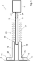
- eine vereinfachte Darstellung eines Setzgeräts gemäß einem ersten Ausführungsbeispiel, bei welcher ein Arbeitskolben des Setzgeräts über eine Federeinrichtung mit einer Vorsatzeinrichtung gekoppelt ist;
- Figur 2
- ein ähnliches Setzgerät wie in
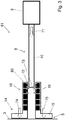
Figur 1 , wobei der Arbeitskolben über eine Reibungs- und/oder Klemmeinrichtung mit der Vorsatzeinrichtung gekoppelt ist und Figur 3- ein ähnliches Setzgerät wie in den
Figuren 1 und2 , wobei der Arbeitskolben über eine Magnetfeldquelle mit der Vorsatzeinrichtung gekoppelt ist.
- FIG. 1
- a simplified representation of a setting device according to a first embodiment, in which a working piston of the setting device is coupled via a spring means with a Vorsatzzeinrichtung;
- FIG. 2
- a similar setting device as in
FIG. 1 , wherein the working piston is coupled via a friction and / or clamping device with the attachment means and - FIG. 3
- a similar setting device as in the
FIGS. 1 and2 , wherein the working piston is coupled via a magnetic field source with the attachment means.
In den
In den
Das in den
Die verwendeten Befestigungselemente werden vorzugsweise über ein geräteinternes Magazin bereitgestellt, das in der Nähe des Austrittsendes oder Setzendes 5 des Setzgeräts 1; 41; 61 angebracht ist. Aus dem Magazin werden die Befestigungselemente, vorzugsweise einzeln, automatisch entnommen und am Setzende 5 bereitgestellt.The fasteners used are preferably provided via a device-internal magazine, which is in the vicinity of the outlet end or setting
Die zum Eintreiben der Befestigungselemente in den Untergrund benötigte Energie wird zum Beispiel in einem Brennstoffbehälter im Inneren des Setzgeräts 1; 41; 61 bereitgestellt. Bei dem Brennstoff in dem Brennstoffbehälter handelt es sich zum Beispiel um Flüssiggas. Daher wird der Brennstoffbehälter auch als Gasdose oder Gaskartusche bezeichnet.The energy required for driving the fasteners into the ground is, for example, in a fuel container in the interior of the setting device 1; 41; 61 provided. The fuel in the fuel container is, for example, LPG. Therefore, the fuel container is also referred to as a gas can or gas cartridge.
Der Brennstoffbehälter ist über eine verstellbare beziehungsweise regelbare Dosiereinrichtung mit einer Verbindungsleitung mit einer Brennkammer oder einem Brennraum verbindbar. Die Dosiereinrichtung ist vorzugsweise als Dosierventil ausgeführt.The fuel tank can be connected via an adjustable or controllable metering device with a connecting line with a combustion chamber or a combustion chamber. The metering device is preferably designed as a metering valve.
In dem Brennraum beziehungsweise der Brennkammer wird Brennstoff, also Gas, aus dem Brennstoffbehälter mit Luft zu einem brennfähigen Gemisch vermischt, das durch eine Zündeinrichtung gezündet wird, um ein Befestigungselement, wie einen Bolzen oder einen Nagel, in den Untergrund einzutreiben. Die zum Eintreiben benötigte Energie wird beim Betätigen eines Abzugs oder Triggers des Setzgeräts 1; 41; 61 über einen Arbeitskolben 8 von der Brennkammer auf ein Befestigungselement am Setzende 5 übertragen.In the combustion chamber or the combustion chamber, fuel, ie gas, from the fuel container mixed with air to form a combustible mixture which is ignited by an ignition device to drive a fastener, such as a bolt or a nail into the ground. The energy required for driving is when pressing a trigger or trigger of the setting device 1; 41; 61 transmitted via a
Der Arbeitskolben 8 umfasst einen Grundkörper 9, von dem ein Stößel 10 ausgeht. Das Setzgerät 1; 41; 61 umfasst des Weiteren eine Vorsatzeinrichtung 14, die vor dem Eintreiben eines Befestigungselements auf den Untergrund 3 aufgesetzt wird. Die Vorsatzeinrichtung 14 umfasst einen Vorsatzteller 15, der an dem Untergrund 3 zur Anlage gebracht wird.The working
Der Vorsatzteller 15 ist einstückig mit einem Führungskörper 16 verbunden, der als Führungshülse ausgeführt ist. Der Führungskörper beziehungsweise die Führungshülse 16 dient zur Darstellung einer Führungseinrichtung 18 für die einzutreibenden Befestigungselemente.The
Der Arbeitskolben 8 ragt mit einem freien Ende des Stößels 10 so in die Führungseinrichtung 18, dass der Stößel 10 in den Führungskörper 16 geführt wird. Beim Eintreiben eines Befestigungselements wird der Stößel 10 weiter in die Führungseinrichtung 16 hinein auf den Untergrund 3 zu bewegt, um das (nicht dargestellte) Befestigungselement in den Untergrund 3 einzutreiben.The working
Beim Setzen von Befestigungselementen, wie Nägeln oder Bolzen, mit herkömmlichen Setzgeräten auf Beton kommt es aufgrund der Beschaffenheit des Untergrunds 3 häufig zu Abplatzungen. Diese Abplatzungen können die Haltekraft des Befestigungselements im Untergrund 3 herabsetzen. Zudem wird das Erscheinungsbild der Haltepunkte auf der ansonsten relativ glatten Untergrundoberfläche, zum Beispiel einer Betonoberfläche, negativ beeinflusst und mindert das Vertrauen in den Befestigungspunkt.When placing fasteners, such as nails or bolts, with conventional setting tools on concrete it often comes to flaking due to the nature of the
Durch die Vorsatzeinrichtung 14 können diese unerwünschten Abplatzungen in ihrem Ausmaß und der Häufigkeit vermindert werden. Gemäß einem wesentlichen Aspekt der Erfindung wird die Energie, die benötigt wird, um die Vorsatzeinrichtung 14 gegen den Untergrund 3 zu drücken, über den Arbeitskolben 8 entnommen. Zu diesem Zweck ist der Arbeitskolben 8 mit der Vorsatzeinrichtung 14 gekoppelt.By means of the
Bei dem in
Durch einen Pfeil 24 ist eine Bewegung des Arbeitskolbens 8 beim Eintreiben eines Befestigungselements angedeutet. Durch die damit verbundene Vorwärtsbewegung des Arbeitskolbens 8 wird die Federeinrichtung 20 gespannt und überträgt einen Teil der Eintreibkraft des Arbeitskolbens 8 auf den Führungskörper 16 der Führungseinrichtung 18 und den Vorsatzteller 15 der Vorsatzeinrichtung 14. Dadurch wird der Vorsatzteller 15 der Vorsatzeinrichtung 14 gegen den Untergrund 3 vorgespannt, wie durch Pfeile 25 und 26 angedeutet ist.By an
Damit der Arbeitskolben 8 seine Eintreibfunktion noch voll erfüllen kann, sollte die Federeinrichtung 20 vorteilhaft mindestens um die Länge eines Befestigungselements einfedern. Anders als dargestellt, kann die Federeinrichtung 20 auch eine Elastomerfeder umfassen. Die Federeinrichtung 20 kann auch eine Luftfeder umfassen, die zum Beispiel einen Staudruck vor dem Arbeitskolben 8 aufbaut.So that the working
Um den Kraftverlauf der Vorspannkraft der Vorsatzeinrichtung 14 zu beeinflussen, kann der Kontaktzeitpunkt zwischen dem Arbeitskolben 8 und der Federeinrichtung 20 durch die Länge der Federeinrichtung 20 variiert werden. Dadurch kann erreicht werden, dass die Kraftübertragung früher oder später einsetzt. Zudem kann die Federkennlinie der Federeinrichtung 20 variiert werden.In order to influence the force curve of the biasing force of the biasing
Bei dem in
Über diesen Kontakt kann der Arbeitskolben 8 eine Axialkraft auf den Führungskörper 16 der Führungseinrichtung 18 und den Vorsatzteller 15 der Vorsatzeinrichtung 14 übertragen, wie durch Pfeile 51; 52, 53 und 54, 55 angedeutet ist. Die Kontaktstelle kann dabei auf verschiedene Weise ausgeführt sein. Wichtig dabei ist, dass ein Verschleiß von Kontaktmaterialien im Betrieb des Setzgeräts 41 berücksichtigt wird. Durch betriebsbedingten Verschleiß der Kontaktmaterialien verändert sich gegebenenfalls der Kraftverlauf der Vorspannkraft der Vorsatzeinrichtung 14.About this contact, the working
Um die Rückführung des Arbeitskolbens 8 nach einem Setzvorgang nicht zu behindern, ist die Reibungs- und/oder Klemmeinrichtung 45 vorzugsweise so ausgelegt, dass die vorab beschriebene Klemmwirkung nur bei einer Vorwärtsbewegung des Arbeitskolbens 8 in Richtung des Pfeils 51 in
Im Betrieb der Reibungs- und/oder Klemmeinrichtung 45 kann der Kraftverlauf der Vorspannkraft der Vorsatzeinrichtung 14 über den Befestigungseintrieb variiert werden. Zu diesem Zweck kann zum Beispiel ein definiertes Profil auf dem Arbeitskolben 8 vorgesehen werden. Über das definierte Profil kann je nach Kolbenposition die Klemmkraft beeinflusst werden.During operation of the friction and / or clamping
Bei dem in
Mit Hilfe der Magnetfeldquelle 65 kann in dem sich schnell bewegenden, aus einem elektromagnetisch leitenden Material gebildeten Arbeitskolben 8 ein Wirbelstrom erzeugt werden. Die Bewegung des Arbeitskolbens 8 beim Eintreiben eines Befestigungselements ist durch einen Pfeil 71 angedeutet.With the aid of the
Durch Pfeile 72 und 73 sind Wirbelströme angedeutet, durch welche der Arbeitskolben 8 relativ zu der Führungseinrichtung 18 und der Vorsatzeinrichtung 14 abgebremst wird. Die damit verbundene Bremskraft führt zu einer durch Pfeile 74 und 75 angedeuteten Vorspannkraft der Vorsatzeinrichtung 14 auf den Untergrund 3. Der Verlauf der Anpresskraft kann zum Beispiel durch die Distanz zwischen den Magneten der Magnetfeldquelle 65 und dem Arbeitskolben 8 oder über verschieden starke Magneten eingestellt werden.By
Claims (10)
- Hand-held or semi-stationary setting tool (1; 41; 61) for driving fastening elements into a base (3) using a working piston (8), with a housing, which comprises an attachment (14) at an outlet end (5), characterised in that the working piston (8) is connected to the attachment (14), in which when driving a fastening element into the base (3) energy may be taken from the working piston (8) and transferred to the attachment (14) in order to press the attachment (14) against the base (3).
- Hand-held or semi-stationary setting tool according to claim 1, characterised in that the working piston (8) is connected to the attachment (14) via a spring device (20).
- Hand-held or semi-stationary setting tool according to claim 2, characterised in that the spring device (20) comprises at least an elastomer spring, a spiral spring (21), a plate spring and/or a fluid spring.
- Hand-held or semi-stationary setting tool according to one of the previous claims, characterised in that the working piston (8) is connected to the attachment (14) via a friction and/or clamping device (45).
- Hand-held or semi-stationary setting tool according to claim 4, characterised in that the friction and/or clamping device (45) is made and arranged so that when driving in a fastening element a part of an axial driving in force is transferred from the working piston (8) to the attachment (14).
- Hand-held or semi-stationary setting tool according to one of claims 4 and 5, characterised in that the friction and/or clamping device (45) is made and arranged so that the working piston (8) is not or only insignificantly prevented from returning after a driving in process.
- Hand-held or semi-stationary setting tool according to one of the previous claims, characterised in that the working piston (8) is connected to the attachment (14) via a source of a magnetic field (65).
- Hand-held or semi-stationary setting tool according to claim 7, characterised in that the source of a magnetic field (65) is integrated into a guide body (16) for guiding the fastening elements at the outlet end (5).
- Hand-held or semi-stationary setting tool according to one of the previous claims, characterised in that the attachment (14) is combined with a guide device (18) for guiding the fastening elements at the outlet end (5).
- Method for operating a hand-held or semi-stationary setting tool for driving fastening elements into a base (3) using a working piston (8), with a housing, which comprises an attachment (14) at an outlet end (5), characterised in that when driving a fastening element into the base (3) energy is taken from the working piston (8) and transferred to the attachment (14) in order to press the attachment (14) against the base (3).
Applications Claiming Priority (2)
| Application Number | Priority Date | Filing Date | Title |
|---|---|---|---|
| EP14163964.1A EP2929983A1 (en) | 2014-04-09 | 2014-04-09 | Handheld and semi-stationary setting tool |
| PCT/EP2015/057001 WO2015155059A1 (en) | 2014-04-09 | 2015-03-31 | Hand-held and semi-stationary setting device |
Publications (2)
| Publication Number | Publication Date |
|---|---|
| EP3129189A1 EP3129189A1 (en) | 2017-02-15 |
| EP3129189B1 true EP3129189B1 (en) | 2018-09-26 |
Family
ID=50442397
Family Applications (2)
| Application Number | Title | Priority Date | Filing Date |
|---|---|---|---|
| EP14163964.1A Withdrawn EP2929983A1 (en) | 2014-04-09 | 2014-04-09 | Handheld and semi-stationary setting tool |
| EP15712939.6A Active EP3129189B1 (en) | 2014-04-09 | 2015-03-31 | Handheld and semi-stationary setting tool |
Family Applications Before (1)
| Application Number | Title | Priority Date | Filing Date |
|---|---|---|---|
| EP14163964.1A Withdrawn EP2929983A1 (en) | 2014-04-09 | 2014-04-09 | Handheld and semi-stationary setting tool |
Country Status (3)
| Country | Link |
|---|---|
| US (1) | US20170095918A1 (en) |
| EP (2) | EP2929983A1 (en) |
| WO (1) | WO2015155059A1 (en) |
Family Cites Families (11)
| Publication number | Priority date | Publication date | Assignee | Title |
|---|---|---|---|---|
| US3072911A (en) * | 1957-12-04 | 1963-01-15 | Sarmi S A Societa D Applic De | Fixing guns adapted to drive nails and the like, such as for example studs and plugsin hard compact materials |
| BE611268A (en) * | 1960-04-07 | |||
| US3514026A (en) * | 1967-09-01 | 1970-05-26 | Trw Inc | Repeating propellant gas powered driving tool |
| DE2042767C3 (en) * | 1970-08-28 | 1981-01-29 | Hilti Ag, Schaan (Liechtenstein) | Powder-powered setting tool for driving nails |
| DE2424774C3 (en) * | 1974-05-22 | 1982-03-11 | Poly Patent AG, Schaan | Ignition device, in particular for an internal combustion bolt setter |
| DE2850273A1 (en) | 1978-11-20 | 1980-05-29 | Hilti Ag | Bolt setting gun with percussive drive - has axially displaceable barrel with rear exhaust-charged shoulder spaced by resilient sleeve |
| DE19800847A1 (en) * | 1997-12-04 | 1999-06-17 | Gerd Dr Ing Kellner | Device for placing a fastening element in a setting surface and using the device |
| DE10048311B4 (en) * | 2000-09-29 | 2012-03-01 | Hilti Aktiengesellschaft | setting tool |
| US6892524B1 (en) * | 2003-11-03 | 2005-05-17 | Illinois Tool Works Inc. | Latching mechanism for combustion chamber plate of a fastener driving tool |
| DE102004043955B4 (en) * | 2004-09-11 | 2006-07-20 | Hilti Ag | Internal combustion setting device |
| DE102005000107B4 (en) * | 2005-08-25 | 2014-03-13 | Hilti Aktiengesellschaft | Pneumatically operated setting tool |
-
2014
- 2014-04-09 EP EP14163964.1A patent/EP2929983A1/en not_active Withdrawn
-
2015
- 2015-03-31 US US15/128,478 patent/US20170095918A1/en not_active Abandoned
- 2015-03-31 WO PCT/EP2015/057001 patent/WO2015155059A1/en active Application Filing
- 2015-03-31 EP EP15712939.6A patent/EP3129189B1/en active Active
Non-Patent Citations (1)
| Title |
|---|
| None * |
Also Published As
| Publication number | Publication date |
|---|---|
| US20170095918A1 (en) | 2017-04-06 |
| EP2929983A1 (en) | 2015-10-14 |
| EP3129189A1 (en) | 2017-02-15 |
| WO2015155059A1 (en) | 2015-10-15 |
Similar Documents
| Publication | Publication Date | Title |
|---|---|---|
| DE10031073B4 (en) | Method of riveting | |
| DE4011778A1 (en) | PNEUMATIC IMPACT TOOL FOR FASTENING ELEMENTS | |
| DE4403526A1 (en) | Bolt-firing tool having a safety device for preventing accidental firing | |
| DE1868901U (en) | SPRINGLESS PRESSURE VALVE. | |
| EP0467834B1 (en) | Powder-actuated fastener driving tool | |
| EP1813393B1 (en) | Fastener setting tool | |
| EP3393714B1 (en) | Combustion-driven setting tool and method for operating such a setting tool | |
| DE10259817B4 (en) | Internal combustion fastener for fasteners | |
| DE102016100940A1 (en) | Motorized scissors | |
| EP3129189B1 (en) | Handheld and semi-stationary setting tool | |
| DE60207589T2 (en) | AIR SUPPLY WELDING PISTOL WITH RETRACTABLE PISTON | |
| DE10228036B4 (en) | Setting device with magazine for fastening elements that can be driven by expanding gases | |
| DE10346985A1 (en) | Hand-operated setting tool | |
| DE10341821B4 (en) | setting tool | |
| EP3129190B1 (en) | Method for operating a hand-held or semi- stationary setting device and corresponding device | |
| DE2319152A1 (en) | TOOL, PREFERABLY PISTOL, FOR INSERTING FASTENERS | |
| EP3230012B1 (en) | Setting device and method for operating same | |
| AT262175B (en) | Device for driving bolts into solid components | |
| DE102011122938B3 (en) | setting tool | |
| DE102012023966B3 (en) | Pneumatic setting apparatus for introduction of plastic material lining in recess for assembling covering parts at bodywork parts of motor car, has pulse device comprising pulse part movably mounted relative to other pulse part | |
| DE2424774A1 (en) | Propellant driven tool for driving bolts - uses caseless cartridges for driving nails of different lengths | |
| EP3083153A1 (en) | Drive-in device | |
| DE1503098C (en) | Combustion bolt setter with thrust piston | |
| EP2929984A1 (en) | Handheld or semi-stationary setting tool | |
| DE183940C (en) |
Legal Events
| Date | Code | Title | Description |
|---|---|---|---|
| STAA | Information on the status of an ep patent application or granted ep patent |
Free format text: STATUS: THE INTERNATIONAL PUBLICATION HAS BEEN MADE |
|
| PUAI | Public reference made under article 153(3) epc to a published international application that has entered the european phase |
Free format text: ORIGINAL CODE: 0009012 |
|
| STAA | Information on the status of an ep patent application or granted ep patent |
Free format text: STATUS: REQUEST FOR EXAMINATION WAS MADE |
|
| 17P | Request for examination filed |
Effective date: 20161109 |
|
| AK | Designated contracting states |
Kind code of ref document: A1 Designated state(s): AL AT BE BG CH CY CZ DE DK EE ES FI FR GB GR HR HU IE IS IT LI LT LU LV MC MK MT NL NO PL PT RO RS SE SI SK SM TR |
|
| AX | Request for extension of the european patent |
Extension state: BA ME |
|
| DAV | Request for validation of the european patent (deleted) | ||
| DAX | Request for extension of the european patent (deleted) | ||
| GRAP | Despatch of communication of intention to grant a patent |
Free format text: ORIGINAL CODE: EPIDOSNIGR1 |
|
| STAA | Information on the status of an ep patent application or granted ep patent |
Free format text: STATUS: GRANT OF PATENT IS INTENDED |
|
| INTG | Intention to grant announced |
Effective date: 20180605 |
|
| GRAS | Grant fee paid |
Free format text: ORIGINAL CODE: EPIDOSNIGR3 |
|
| GRAA | (expected) grant |
Free format text: ORIGINAL CODE: 0009210 |
|
| STAA | Information on the status of an ep patent application or granted ep patent |
Free format text: STATUS: THE PATENT HAS BEEN GRANTED |
|
| AK | Designated contracting states |
Kind code of ref document: B1 Designated state(s): AL AT BE BG CH CY CZ DE DK EE ES FI FR GB GR HR HU IE IS IT LI LT LU LV MC MK MT NL NO PL PT RO RS SE SI SK SM TR |
|
| REG | Reference to a national code |
Ref country code: GB Ref legal event code: FG4D Free format text: NOT ENGLISH |
|
| REG | Reference to a national code |
Ref country code: CH Ref legal event code: EP |
|
| REG | Reference to a national code |
Ref country code: AT Ref legal event code: REF Ref document number: 1045440 Country of ref document: AT Kind code of ref document: T Effective date: 20181015 |
|
| REG | Reference to a national code |
Ref country code: IE Ref legal event code: FG4D Free format text: LANGUAGE OF EP DOCUMENT: GERMAN |
|
| REG | Reference to a national code |
Ref country code: DE Ref legal event code: R096 Ref document number: 502015006084 Country of ref document: DE |
|
| REG | Reference to a national code |
Ref country code: NL Ref legal event code: MP Effective date: 20180926 |
|
| PG25 | Lapsed in a contracting state [announced via postgrant information from national office to epo] |
Ref country code: NO Free format text: LAPSE BECAUSE OF FAILURE TO SUBMIT A TRANSLATION OF THE DESCRIPTION OR TO PAY THE FEE WITHIN THE PRESCRIBED TIME-LIMIT Effective date: 20181226 Ref country code: SE Free format text: LAPSE BECAUSE OF FAILURE TO SUBMIT A TRANSLATION OF THE DESCRIPTION OR TO PAY THE FEE WITHIN THE PRESCRIBED TIME-LIMIT Effective date: 20180926 Ref country code: RS Free format text: LAPSE BECAUSE OF FAILURE TO SUBMIT A TRANSLATION OF THE DESCRIPTION OR TO PAY THE FEE WITHIN THE PRESCRIBED TIME-LIMIT Effective date: 20180926 Ref country code: GR Free format text: LAPSE BECAUSE OF FAILURE TO SUBMIT A TRANSLATION OF THE DESCRIPTION OR TO PAY THE FEE WITHIN THE PRESCRIBED TIME-LIMIT Effective date: 20181227 Ref country code: FI Free format text: LAPSE BECAUSE OF FAILURE TO SUBMIT A TRANSLATION OF THE DESCRIPTION OR TO PAY THE FEE WITHIN THE PRESCRIBED TIME-LIMIT Effective date: 20180926 Ref country code: BG Free format text: LAPSE BECAUSE OF FAILURE TO SUBMIT A TRANSLATION OF THE DESCRIPTION OR TO PAY THE FEE WITHIN THE PRESCRIBED TIME-LIMIT Effective date: 20181226 Ref country code: LT Free format text: LAPSE BECAUSE OF FAILURE TO SUBMIT A TRANSLATION OF THE DESCRIPTION OR TO PAY THE FEE WITHIN THE PRESCRIBED TIME-LIMIT Effective date: 20180926 |
|
| REG | Reference to a national code |
Ref country code: LT Ref legal event code: MG4D |
|
| PG25 | Lapsed in a contracting state [announced via postgrant information from national office to epo] |
Ref country code: AL Free format text: LAPSE BECAUSE OF FAILURE TO SUBMIT A TRANSLATION OF THE DESCRIPTION OR TO PAY THE FEE WITHIN THE PRESCRIBED TIME-LIMIT Effective date: 20180926 Ref country code: LV Free format text: LAPSE BECAUSE OF FAILURE TO SUBMIT A TRANSLATION OF THE DESCRIPTION OR TO PAY THE FEE WITHIN THE PRESCRIBED TIME-LIMIT Effective date: 20180926 Ref country code: HR Free format text: LAPSE BECAUSE OF FAILURE TO SUBMIT A TRANSLATION OF THE DESCRIPTION OR TO PAY THE FEE WITHIN THE PRESCRIBED TIME-LIMIT Effective date: 20180926 |
|
| PG25 | Lapsed in a contracting state [announced via postgrant information from national office to epo] |
Ref country code: PL Free format text: LAPSE BECAUSE OF FAILURE TO SUBMIT A TRANSLATION OF THE DESCRIPTION OR TO PAY THE FEE WITHIN THE PRESCRIBED TIME-LIMIT Effective date: 20180926 Ref country code: EE Free format text: LAPSE BECAUSE OF FAILURE TO SUBMIT A TRANSLATION OF THE DESCRIPTION OR TO PAY THE FEE WITHIN THE PRESCRIBED TIME-LIMIT Effective date: 20180926 Ref country code: IS Free format text: LAPSE BECAUSE OF FAILURE TO SUBMIT A TRANSLATION OF THE DESCRIPTION OR TO PAY THE FEE WITHIN THE PRESCRIBED TIME-LIMIT Effective date: 20190126 Ref country code: RO Free format text: LAPSE BECAUSE OF FAILURE TO SUBMIT A TRANSLATION OF THE DESCRIPTION OR TO PAY THE FEE WITHIN THE PRESCRIBED TIME-LIMIT Effective date: 20180926 Ref country code: NL Free format text: LAPSE BECAUSE OF FAILURE TO SUBMIT A TRANSLATION OF THE DESCRIPTION OR TO PAY THE FEE WITHIN THE PRESCRIBED TIME-LIMIT Effective date: 20180926 Ref country code: CZ Free format text: LAPSE BECAUSE OF FAILURE TO SUBMIT A TRANSLATION OF THE DESCRIPTION OR TO PAY THE FEE WITHIN THE PRESCRIBED TIME-LIMIT Effective date: 20180926 Ref country code: ES Free format text: LAPSE BECAUSE OF FAILURE TO SUBMIT A TRANSLATION OF THE DESCRIPTION OR TO PAY THE FEE WITHIN THE PRESCRIBED TIME-LIMIT Effective date: 20180926 Ref country code: IT Free format text: LAPSE BECAUSE OF FAILURE TO SUBMIT A TRANSLATION OF THE DESCRIPTION OR TO PAY THE FEE WITHIN THE PRESCRIBED TIME-LIMIT Effective date: 20180926 |
|
| PG25 | Lapsed in a contracting state [announced via postgrant information from national office to epo] |
Ref country code: SK Free format text: LAPSE BECAUSE OF FAILURE TO SUBMIT A TRANSLATION OF THE DESCRIPTION OR TO PAY THE FEE WITHIN THE PRESCRIBED TIME-LIMIT Effective date: 20180926 Ref country code: PT Free format text: LAPSE BECAUSE OF FAILURE TO SUBMIT A TRANSLATION OF THE DESCRIPTION OR TO PAY THE FEE WITHIN THE PRESCRIBED TIME-LIMIT Effective date: 20190126 Ref country code: SM Free format text: LAPSE BECAUSE OF FAILURE TO SUBMIT A TRANSLATION OF THE DESCRIPTION OR TO PAY THE FEE WITHIN THE PRESCRIBED TIME-LIMIT Effective date: 20180926 |
|
| REG | Reference to a national code |
Ref country code: DE Ref legal event code: R097 Ref document number: 502015006084 Country of ref document: DE |
|
| PG25 | Lapsed in a contracting state [announced via postgrant information from national office to epo] |
Ref country code: DK Free format text: LAPSE BECAUSE OF FAILURE TO SUBMIT A TRANSLATION OF THE DESCRIPTION OR TO PAY THE FEE WITHIN THE PRESCRIBED TIME-LIMIT Effective date: 20180926 |
|
| PLBE | No opposition filed within time limit |
Free format text: ORIGINAL CODE: 0009261 |
|
| STAA | Information on the status of an ep patent application or granted ep patent |
Free format text: STATUS: NO OPPOSITION FILED WITHIN TIME LIMIT |
|
| 26N | No opposition filed |
Effective date: 20190627 |
|
| PG25 | Lapsed in a contracting state [announced via postgrant information from national office to epo] |
Ref country code: MC Free format text: LAPSE BECAUSE OF FAILURE TO SUBMIT A TRANSLATION OF THE DESCRIPTION OR TO PAY THE FEE WITHIN THE PRESCRIBED TIME-LIMIT Effective date: 20180926 Ref country code: SI Free format text: LAPSE BECAUSE OF FAILURE TO SUBMIT A TRANSLATION OF THE DESCRIPTION OR TO PAY THE FEE WITHIN THE PRESCRIBED TIME-LIMIT Effective date: 20180926 |
|
| REG | Reference to a national code |
Ref country code: CH Ref legal event code: PL |
|
| PG25 | Lapsed in a contracting state [announced via postgrant information from national office to epo] |
Ref country code: LU Free format text: LAPSE BECAUSE OF NON-PAYMENT OF DUE FEES Effective date: 20190331 |
|
| REG | Reference to a national code |
Ref country code: BE Ref legal event code: MM Effective date: 20190331 |
|
| PG25 | Lapsed in a contracting state [announced via postgrant information from national office to epo] |
Ref country code: IE Free format text: LAPSE BECAUSE OF NON-PAYMENT OF DUE FEES Effective date: 20190331 Ref country code: CH Free format text: LAPSE BECAUSE OF NON-PAYMENT OF DUE FEES Effective date: 20190331 Ref country code: LI Free format text: LAPSE BECAUSE OF NON-PAYMENT OF DUE FEES Effective date: 20190331 |
|
| PG25 | Lapsed in a contracting state [announced via postgrant information from national office to epo] |
Ref country code: BE Free format text: LAPSE BECAUSE OF NON-PAYMENT OF DUE FEES Effective date: 20190331 |
|
| PG25 | Lapsed in a contracting state [announced via postgrant information from national office to epo] |
Ref country code: TR Free format text: LAPSE BECAUSE OF FAILURE TO SUBMIT A TRANSLATION OF THE DESCRIPTION OR TO PAY THE FEE WITHIN THE PRESCRIBED TIME-LIMIT Effective date: 20180926 |
|
| PG25 | Lapsed in a contracting state [announced via postgrant information from national office to epo] |
Ref country code: MT Free format text: LAPSE BECAUSE OF FAILURE TO SUBMIT A TRANSLATION OF THE DESCRIPTION OR TO PAY THE FEE WITHIN THE PRESCRIBED TIME-LIMIT Effective date: 20180926 |
|
| REG | Reference to a national code |
Ref country code: AT Ref legal event code: MM01 Ref document number: 1045440 Country of ref document: AT Kind code of ref document: T Effective date: 20200331 |
|
| PG25 | Lapsed in a contracting state [announced via postgrant information from national office to epo] |
Ref country code: CY Free format text: LAPSE BECAUSE OF FAILURE TO SUBMIT A TRANSLATION OF THE DESCRIPTION OR TO PAY THE FEE WITHIN THE PRESCRIBED TIME-LIMIT Effective date: 20180926 |
|
| PG25 | Lapsed in a contracting state [announced via postgrant information from national office to epo] |
Ref country code: HU Free format text: LAPSE BECAUSE OF FAILURE TO SUBMIT A TRANSLATION OF THE DESCRIPTION OR TO PAY THE FEE WITHIN THE PRESCRIBED TIME-LIMIT; INVALID AB INITIO Effective date: 20150331 |
|
| PG25 | Lapsed in a contracting state [announced via postgrant information from national office to epo] |
Ref country code: AT Free format text: LAPSE BECAUSE OF NON-PAYMENT OF DUE FEES Effective date: 20200331 |
|
| PG25 | Lapsed in a contracting state [announced via postgrant information from national office to epo] |
Ref country code: MK Free format text: LAPSE BECAUSE OF FAILURE TO SUBMIT A TRANSLATION OF THE DESCRIPTION OR TO PAY THE FEE WITHIN THE PRESCRIBED TIME-LIMIT Effective date: 20180926 |
|
| PGFP | Annual fee paid to national office [announced via postgrant information from national office to epo] |
Ref country code: FR Payment date: 20230324 Year of fee payment: 9 |
|
| PGFP | Annual fee paid to national office [announced via postgrant information from national office to epo] |
Ref country code: DE Payment date: 20240320 Year of fee payment: 10 Ref country code: GB Payment date: 20240320 Year of fee payment: 10 |