EP3129134B1 - Strahlungsquellenbaugruppe - Google Patents
Strahlungsquellenbaugruppe Download PDFInfo
- Publication number
- EP3129134B1 EP3129134B1 EP15776430.9A EP15776430A EP3129134B1 EP 3129134 B1 EP3129134 B1 EP 3129134B1 EP 15776430 A EP15776430 A EP 15776430A EP 3129134 B1 EP3129134 B1 EP 3129134B1
- Authority
- EP
- European Patent Office
- Prior art keywords
- lamp plug
- radiation source
- sleeve bolt
- lamp
- retaining element
- Prior art date
- Legal status (The legal status is an assumption and is not a legal conclusion. Google has not performed a legal analysis and makes no representation as to the accuracy of the status listed.)
- Active
Links
Images


Classifications
-
- C—CHEMISTRY; METALLURGY
- C02—TREATMENT OF WATER, WASTE WATER, SEWAGE, OR SLUDGE
- C02F—TREATMENT OF WATER, WASTE WATER, SEWAGE, OR SLUDGE
- C02F1/00—Treatment of water, waste water, or sewage
- C02F1/30—Treatment of water, waste water, or sewage by irradiation
- C02F1/32—Treatment of water, waste water, or sewage by irradiation with ultraviolet light
- C02F1/325—Irradiation devices or lamp constructions
-
- A—HUMAN NECESSITIES
- A61—MEDICAL OR VETERINARY SCIENCE; HYGIENE
- A61L—METHODS OR APPARATUS FOR STERILISING MATERIALS OR OBJECTS IN GENERAL; DISINFECTION, STERILISATION OR DEODORISATION OF AIR; CHEMICAL ASPECTS OF BANDAGES, DRESSINGS, ABSORBENT PADS OR SURGICAL ARTICLES; MATERIALS FOR BANDAGES, DRESSINGS, ABSORBENT PADS OR SURGICAL ARTICLES
- A61L2/00—Disinfection or sterilisation of materials or objects, in general; Accessories therefor
- A61L2/02—Disinfection or sterilisation of materials or objects, in general; Accessories therefor using physical processes
- A61L2/08—Radiation
-
- H—ELECTRICITY
- H01—ELECTRIC ELEMENTS
- H01J—ELECTRIC DISCHARGE TUBES OR DISCHARGE LAMPS
- H01J5/00—Details relating to vessels or to leading-in conductors common to two or more basic types of discharge tubes or lamps
- H01J5/50—Means forming part of the tube or lamps for the purpose of providing electrical connection to it
- H01J5/54—Means forming part of the tube or lamps for the purpose of providing electrical connection to it supported by a separate part, e.g. base
- H01J5/58—Means for fastening the separate part to the vessel, e.g. by cement
- H01J5/60—Means for fastening the separate part to the vessel, e.g. by cement for fastening by mechanical means
-
- H—ELECTRICITY
- H01—ELECTRIC ELEMENTS
- H01J—ELECTRIC DISCHARGE TUBES OR DISCHARGE LAMPS
- H01J61/00—Gas-discharge or vapour-discharge lamps
- H01J61/02—Details
-
- H—ELECTRICITY
- H01—ELECTRIC ELEMENTS
- H01J—ELECTRIC DISCHARGE TUBES OR DISCHARGE LAMPS
- H01J61/00—Gas-discharge or vapour-discharge lamps
- H01J61/02—Details
- H01J61/36—Seals between parts of vessels; Seals for leading-in conductors; Leading-in conductors
-
- C—CHEMISTRY; METALLURGY
- C02—TREATMENT OF WATER, WASTE WATER, SEWAGE, OR SLUDGE
- C02F—TREATMENT OF WATER, WASTE WATER, SEWAGE, OR SLUDGE
- C02F2201/00—Apparatus for treatment of water, waste water or sewage
- C02F2201/32—Details relating to UV-irradiation devices
- C02F2201/322—Lamp arrangement
- C02F2201/3227—Units with two or more lamps
Definitions
- the present invention relates to a radiation source assembly.
- Other aspects of the invention will become apparent to those of skill in the art upon reviewing the present specification.
- Fluid treatment systems are known generally in the art.
- Such systems include an array of UV lamp frames which include several U V lamps each of which are mounted within sleeves which extend between and are supported by a pair of legs which are attached to a cross-piece.
- the so-supported sleeves (containing the UV lamps) are immersed into a fluid to be treated which is then irradiated as required.
- the amount of radiation to which the fluid is exposed is determined by the proximity of the fluid to the lamps, the output wattage of the lamps and the fluid's flow rate past the lamps.
- one or more UV sensors may be employed to monitor the UV output of the lamps and the fluid level is typically controlled, to some extent, downstream of the treatment device by means of level gates or the like.
- the radiation source is disposed in the fluid to be treated in a manner such that the longitudinal axis of the radiation source is in a transverse (e.g., substantially orthogonal or vertical orientation of the radiation sources) relationship with respect to the direction of fluid flow past the radiation source.
- a transverse e.g., substantially orthogonal or vertical orientation of the radiation sources
- the UV lamps are conventionally housed in a protective quartz sleeve within a housing or chamber filled with water.
- the water in the housing or chamber is normally pressurized. This pressure applies a force to the closed end of the sleeve.
- the sleeve is held in position by a sleeve bolt fastened to the water chamber.
- the sleeve is sealed within the chamber to prevent water from leaking out of the housing or chamber.
- the lamp and its electrical plug are housed within this quartz sleeve and can be removed without breaking the housing/chamber water seal.
- a seal on the lamp plug prevents water from entering the sleeve from the external environment or allowing water to leak if the sleeve breaks.
- the lamp plug is mechanically fastened to the sleeve bolt.
- WO 2012/037644 teaches a radiation source assembly comprising an elongate radiation source; a reactor port for receiving and reversibly securing the elongate radiation source; a top plug element for reversible connection to a proximal end of the radiation source and reversible engagement with the reactor port; the top plug element configured to be disengaged from reactor port without disengagement of the elongate radiation source from the reactor port.
- the radiation source assembly comprises a flanged connection bolted to the fluid housing/chamber.
- a lamp plug is locked into the sleeve bolt with a bayonet style feature.
- a locking pin is configured to prevent the bayonet feature from rotating accidentally in case of quartz sleeve failure - this is a desirable and important safety feature of the bayonet arrangement taught by Moglan.
- the flanged connection and the bayonet feature serve to fix the orientation of the lamp plug.
- the bayonet connection is the only mechanism capable of holding the lamp plug in position in case of quartz sleeve failure.
- embodiments of the bayonet connection illustrated in Moglan necessitate that the lamp plug be twisted or rotated to engage or disengage the electrical connections of the radiation source. Consequently, additional structure and space is needed to engage/disengage the lamp plug and the electrical connections to account for the fact that the lamp plug is being twisted or rotated and the electrical connections of the radiation source are relatively stationary. Further relevant documents are US 5 030 125 , WO 2006/092111 , EP 0 202 820 .
- a coupling for radiation source assembly is provided in independent claim 1, which comprises the essential features of the invention.
- the invention also relates to a radiation source assembly as defined in claim 5. Preferred embodiments are described in dependent claims 2-4.
- the present disclosure provides a radiation source assembly comprising:
- the disclosure also relates to a fluid treatment system incorporating this radiation source assembly.
- the present inventor has developed a coupling for a radiation source assembly that comprises an elongate radiation source and an elongate radiation transparent protective sleeve for receiving the elongate radiation source.
- the coupling disengages in two stages when it is desired to remove the elongate radiation source for servicing (or any other purpose).
- the coupling is disengaged from a first position in which a seal is made between the sleeve bolt element and the lamp plug element.
- the lamp plug element is still secure with respect to the sleeve bolt element but since there is no seal between the two, any fluid which has flooded the elongate radiation source (e.g., due to breakage or other damage to the protective sleeve) will emerge from the coupling warning the operator not to fully disengage the lamp plug element from the sleeve bolt element. If no such fluid is seen by operator, the operator may continue to disengage the lamp plug element from the sleeve bolt element to withdraw the elongate radiation source from the elongate radiation transparent protective sleeve.
- any fluid which has flooded the elongate radiation source e.g., due to breakage or other damage to the protective sleeve
- the present coupling and radiation source assembly operates on the basis that the lamp plug element can be disengaged from the sleeve bolt element without the need for any rotation of the lamp plug element. This avoids the requirement for additional structure to create the electrical connection between the lamp plug element and the electrical connectors on the elongate radiation source. This also results in a smaller footprint for construction which facilitates closer packing of radiation source assemblies in the fluid treatment system.
- the present invention relates to a radiation source assembly comprising: an elongate radiation source; an elongate radiation transparent protective sleeve for receiving the elongate radiation source; a sleeve bolt element configured to secure the protective sleeve to a fluid treatment housing; a lamp plug element configured to: (i) be reversibly engageable with respect to the elongate radiation source, and (ii) supply electrical power to the elongate radiation source; and a first seal element configured to be moveable between a first position in which the first seal provides a substantially fluid tight seal between the sleeve bolt element and the lamp plug element and a second position in which the sleeve bolt element and the lamp plug element are unsealed upon non-rotational retraction of the lamp plug element in a direction substantially parallel to a longitudinal axis of the elongate radiation source.
- the present invention provides a coupling for a radiation source assembly comprising an elongate radiation source and an elongate radiation transparent protective sleeve for receiving the elongate radiation source, the coupling comprising: a sleeve bolt element configured to secure the protective sleeve to a fluid treatment housing; a lamp plug element configured to: (i) be reversibly engageable with respect to the elongate radiation source, and (ii) supply electrical power to the elongate radiation source; and a first seal element configured to be moveable between a first position in which the first seal provides a substantially fluid tight seal between the sleeve bolt element and the lamp plug element and a second position in which the sleeve bolt element and the lamp plug element are unsealed upon non-rotational retraction of the lamp plug element in a direction substantially parallel to a longitudinal axis of the elongate radiation source.
- Another aspect of the present disclosure relates to a fluid treatment system comprising the radiation source assembly described above. Further aspects of either of these fluid treatment systems may include any one or a combination of any two or more of any of the following features:
- Radiation source assembly 100 comprises a radiation source 105 disposed within a protective sleeve 110. This will be apparent to those of ordinary skill in the art. Only a proximal portion of radiation source 105 and protective sleeve 110 is shown for clarity purposes.
- Radiation source 105 and protective sleeve 110 are secured to a wall 115 of a fluid treatment system by a coupling 120. As shown, a significant portion of radiation source 105 and protective sleeve 110 is disposed in a fluid treatment zone 117 of the fluid treatment.
- Coupling 120 comprises a sleeve bolt element 125, a lamp plug retaining element 145 and a lamp plug element 150.
- Sleeve bolt element 125 is secured to wall 115 of the fluid treatment zone by any suitable means (e.g., threaded portion, welding and the like - not shown for clarity).
- An O-ring 127 is disposed to be in contact with wall 115 of the fluid treatment system, sleeve bolt element 125 and protective sleeve 110 to provide a substantially fluid tight seal to prevent leakage of fluid from fluid treatment zone 117 (e.g., water from a pressurized water treatment zone).
- Sleeve bolt element 125 comprises threaded portions 130,140 which are separated by a space portion 135.
- Lamp plug retaining element 145 comprises a threaded portion 147 and a proximal portion 149 which is received in a recess 155 in lamp plug element 150.
- An O-ring 160 is provided in a recess 157 in lamp plug element 150.
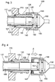
- lamp plug retaining element 145 When it is desired to access radiation source 105 for servicing (or any other purpose), lamp plug retaining element 145 is rotated to disengage threaded portion 130 of sleeve bolt element 125 from threaded portion 147 of lamp plug retaining element 145. This results in threaded portion 147 of lamp plug retaining element 145 moving into space portion 135 of sleeve bolt element 125 - see Figure 3 .
- any fluid e.g., water from fluid treatment zone 117
- any fluid e.g., water from fluid treatment zone 117
- fluid treatment zone 117 contains a pressurized flow of fluid (e.g., water).
- the appearance of any fluid leakage alerts the operator to shut down the fluid treatment system and thereafter remove both radiation source 105 and protective sleeve 110. This is significant safety advantage of the present coupling and radiation source assembly.
- the operator may continue with disengagement of lamp plug element 150 from sleeve bolt element 125. This may be achieved by turning lamp plug retaining element 145 such that is engages and then disengages from threaded portion 140 on sleeve bolt element 125 - see Figure 4 . At this point, it is possible to withdraw radiation source 105 by continuing to retract lamp plug element 150 in the direction of arrow A. This allows for servicing of radiation source 105 while maintaining the fluid treatment system in operation.
- FIG. 5-8 there is shown a second embodiment of the present radiation source assembly and coupling.
- elements with the same last two numerals are intended to denote similar elements in the embodiment illustrated in Figures 1-4 .
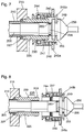
- Figure 5 illustrates coupling 220 when the radiation source assembly is in an "in use” configuration.
- locking collar 245a is retracted toward lamp plug element 250.
- This action results in balls 244 clearing ridge element 230 such that balls 244 are received in a receptacle or recess 243 in outer locking ring 245a - see Figure 7 .
- This has the effect of placing O-ring 260 in the so-called second position described above. At this point, the operator will be able to tell if there is fluid leakage from the radiation source assembly due to breakage or other damage to protective sleeve 210.
- the operator can continue to disengage lamp plug element 250 by turning lamp plug retaining element 245b such that threaded portion 247 thereof engages and then disengages threaded portion 240 of sleeve bolt element 225 - see Figure 8 .
Landscapes
- Health & Medical Sciences (AREA)
- Life Sciences & Earth Sciences (AREA)
- Water Supply & Treatment (AREA)
- Hydrology & Water Resources (AREA)
- Engineering & Computer Science (AREA)
- Environmental & Geological Engineering (AREA)
- Toxicology (AREA)
- Chemical & Material Sciences (AREA)
- Organic Chemistry (AREA)
- Epidemiology (AREA)
- Animal Behavior & Ethology (AREA)
- General Health & Medical Sciences (AREA)
- Public Health (AREA)
- Veterinary Medicine (AREA)
- Physical Water Treatments (AREA)
Claims (5)
- Kupplung (120; 220) für eine Strahlungsquellenanordnung (100; 200), die eine längliche Strahlungsquelle (105; 205) und eine längliche strahlungstransparente Schutzhülse (110; 210) zur Aufnahme der länglichen Strahlungsquelle (105; 205) umfasst, wobei die Kupplung (120; 220) umfasst:- ein Hülsenbolzenelement (125; 225), das so ausgelegt ist, dass es die Schutzhülse (110; 210) an einer Wand (115; 215) eines Fluidbehandlungsgehäuses befestigt;- ein Lampensteckerelement (150; 250), das dafür ausgelegt ist: (i) in Bezug auf die längliche Strahlungsquelle (105; 205) reversibel in Eingriff gebracht zu werden und (ii) die längliche Strahlungsquelle (105; 205) mit elektrischer Energie zu versorgen;- ein Lampenstecker-Halteelement (145; 245a, 245b), das mit dem Lampensteckerelement (150; 250) in Eingriff steht;- ein Dichtungselement (160; 260), wobei das Lampensteckerelement (150; 250) einen Aussparungsbereich (157) zur Aufnahme des Dichtungselementes (160; 260) umfasst, wobei das Dichtungselement (160; 260) eine ringförmige Ausbildung aufweist;- wobei das Hülsenbolzenelement (125; 225) einen ersten Verriegelungsabschnitt (130; 230) umfasst und das Lampenstecker-Halteelement (145; 245a, 245b) ebenfalls einen Verriegelungsabschnitt umfasst, der so ausgestaltet ist, dass er lösbar in den ersten Verriegelungsabschnitt eingreift, um das Lampenstecker-Halteelement (145; 245a, 245b) in einer ersten gestreckten Position zu sichern, die einer ersten Position der Dichtung (160; 260) entspricht, in der die Dichtung (160, 260) für eine fluiddichte Abdichtung zwischen dem Hülsenbolzenelement (125; 225) und dem Lampenstecker-Element (150; 250) sorgt;- wobei das Lampenstecker-Halteelement (145; 245a, 245b) so ausgelegt ist, dass es in eine zweite zurückgezogene Position bewegt werden kann, wobei das Lampenstecker-Element (150; 250) gleichzeitig ein nicht-rotierendes Zurückziehen in einer Richtung im Wesentlichen parallel zu einer Längsachse der länglichen Strahlungsquelle (105; 205) ausführt, wobei die zweite zurückgezogene Position des Lampenstecker-Halteelements (145; 245a, 245b) einer zweiten Position der Dichtung (160; 260) entspricht, in der das Hülsenbolzenelement (125; 225) und das Lampenstecker-Element (150; 250) nicht abgedichtet sind;- wobei das Hülsenbolzenelement (125; 225) ferner einen Gewindeabschnitt (140; 240) umfasst, der von dem ersten Verriegelungsabschnitt (130; 230) durch einen Abstandsabschnitt (135; 235) getrennt ist, und wobei das Lampenstecker-Halteelement (145; 245a, 245b) einen Gewindeabschnitt (147; 247) umfasst, sodass, wenn das Lampenstecker-Halteelement (145; 245a, 245b) in der zweiten zurückgezogenen Position ist, der Gewindeabschnitt (147; 247) des Lampenstecker-Halteelements (145; 245a, 245b) in dem Abstandsabschnitt (135; 235) des Hülsenbolzenelements (125; 225) ist und durch den Gewindeabschnitt (140; 240) des Hülsenbolzenelements (125; 225) an einem weiteren Zurückziehen gehindert wird;- wobei das Lampenstecker-Element (150; 250) dann weiter von dem Hülsenbolzen-Element (125; 225) gelöst werden kann, indem das Lampenstecker-Halteelement (145; 245a, 245b) gedreht wird, sodass sein Gewindeabschnitt (147; 247) in den Gewindeabschnitt (140; 240) des HülsenbolzenElements eingreift und dann von diesem gelöst wird.
- Kupplung nach Anspruch (1), dadurch gekennzeichnet, dass das Lampenstecker-Halteelement (245a; 245b) einen Sicherungsring (245a) und ein Stecker-Halteelement (245b) umfasst, die miteinander zusammenwirken, wobei zwischen dem Sicherungsring (245a) und dem Stecker-Halteelement (245b) eine ringförmige Anordnung von Kugeln (244) und ein Schraubenfederelement (248) angeordnet ist.
- Kupplung nach Anspruch 2, dadurch gekennzeichnet, dass der Sicherungsring (245a) einen Aussparungsbereich (243) zur Aufnahme der ringförmigen Anordnung von Kugeln (244) umfasst.
- Kupplung nach einem der Ansprüche 1 bis 3, dadurch gekennzeichnet, dass das Hülsenbolzenelement (125; 225) einen ersten Gewindeabschnitt (130) oder einen ersten Stegabschnitt (230) umfasst, der in der ersten ausgefahrenen Position mit dem Lampenstecker-Halteelement (145; 245a, 245b) zusammenwirkt.
- Strahlungsquellenanordnung (100; 200), umfassend:eine längliche Strahlungsquelle (105; 205);eine längliche strahlungsdurchlässige Schutzhülle (110; 210) zur Aufnahme der länglichen Strahlungsquelle; unddie in einem der Ansprüche (1-4) definierte Kupplung.
Applications Claiming Priority (2)
| Application Number | Priority Date | Filing Date | Title |
|---|---|---|---|
| US201461995466P | 2014-04-11 | 2014-04-11 | |
| PCT/CA2015/000234 WO2015154166A1 (en) | 2014-04-11 | 2015-04-10 | Radiation source assembly |
Publications (3)
| Publication Number | Publication Date |
|---|---|
| EP3129134A1 EP3129134A1 (de) | 2017-02-15 |
| EP3129134A4 EP3129134A4 (de) | 2017-10-04 |
| EP3129134B1 true EP3129134B1 (de) | 2021-06-02 |
Family
ID=54287043
Family Applications (1)
| Application Number | Title | Priority Date | Filing Date |
|---|---|---|---|
| EP15776430.9A Active EP3129134B1 (de) | 2014-04-11 | 2015-04-10 | Strahlungsquellenbaugruppe |
Country Status (5)
| Country | Link |
|---|---|
| US (1) | US9856153B2 (de) |
| EP (1) | EP3129134B1 (de) |
| CN (1) | CN106536038A (de) |
| CA (1) | CA2944921C (de) |
| WO (1) | WO2015154166A1 (de) |
Cited By (1)
| Publication number | Priority date | Publication date | Assignee | Title |
|---|---|---|---|---|
| EP4415766A4 (de) * | 2021-10-13 | 2025-08-27 | Trojan Tech Group Ulc | Uv-strahlungsquellenanordnung |
Families Citing this family (3)
| Publication number | Priority date | Publication date | Assignee | Title |
|---|---|---|---|---|
| US10343935B2 (en) | 2015-07-14 | 2019-07-09 | Trojan Technologies | Fluid treatment system |
| EP4286029A3 (de) * | 2015-09-25 | 2023-12-20 | Seoul Viosys Co., Ltd. | Sterilisationsmodul, wasserreinigungsvorrichtung und system mit wasserreinigungsvorrichtung |
| KR102864254B1 (ko) * | 2016-12-16 | 2025-09-26 | 엘지전자 주식회사 | 살균 모듈 및 이를 구비한 정수기 |
Family Cites Families (5)
| Publication number | Priority date | Publication date | Assignee | Title |
|---|---|---|---|---|
| GB8513170D0 (en) * | 1985-05-24 | 1985-06-26 | Still & Sons Ltd W M | Water purifiers |
| US5030125A (en) * | 1989-09-29 | 1991-07-09 | Aquafine Corporation | Attachment assembly for ultraviolet light lamp apparatus |
| DE102005010070A1 (de) * | 2005-03-04 | 2006-09-07 | Patent-Treuhand-Gesellschaft für elektrische Glühlampen mbH | UV-Einbaustrahler und Entkeimungssystem mit diesem UV-Einbaustrahler |
| EP2614300B1 (de) * | 2010-09-10 | 2016-12-28 | Trojan Technologies | Strahlungsquellenbaugruppe |
| CN102728293A (zh) * | 2010-10-04 | 2012-10-17 | 特洁安科技有限公司 | 套筒支持器装置 |
-
2015
- 2015-04-10 US US15/302,618 patent/US9856153B2/en active Active
- 2015-04-10 WO PCT/CA2015/000234 patent/WO2015154166A1/en not_active Ceased
- 2015-04-10 EP EP15776430.9A patent/EP3129134B1/de active Active
- 2015-04-10 CA CA2944921A patent/CA2944921C/en active Active
- 2015-04-10 CN CN201580019210.8A patent/CN106536038A/zh active Pending
Non-Patent Citations (1)
| Title |
|---|
| None * |
Cited By (1)
| Publication number | Priority date | Publication date | Assignee | Title |
|---|---|---|---|---|
| EP4415766A4 (de) * | 2021-10-13 | 2025-08-27 | Trojan Tech Group Ulc | Uv-strahlungsquellenanordnung |
Also Published As
| Publication number | Publication date |
|---|---|
| CA2944921A1 (en) | 2015-10-15 |
| EP3129134A1 (de) | 2017-02-15 |
| EP3129134A4 (de) | 2017-10-04 |
| WO2015154166A1 (en) | 2015-10-15 |
| US20170022073A1 (en) | 2017-01-26 |
| CA2944921C (en) | 2020-03-10 |
| CN106536038A (zh) | 2017-03-22 |
| US9856153B2 (en) | 2018-01-02 |
Similar Documents
| Publication | Publication Date | Title |
|---|---|---|
| US9856153B2 (en) | Radiation source assembly | |
| CN103080645B (zh) | 辐射源组件 | |
| RU2626130C2 (ru) | Медицинский инструмент и штыревой соединитель для этого инструмента | |
| KR100799294B1 (ko) | 화력발전소 석탄분쇄용 미분기 화재 감지장치 | |
| KR20170067752A (ko) | 수동형 일체형 차단 밸브 | |
| US8866105B2 (en) | Sleeve holder assembly | |
| TW200733139A (en) | Feed system and relative operating procedure | |
| US9682873B2 (en) | UV lamp module with exchangeable lamp units | |
| CA2599497C (en) | Monitoring port assembly for fluid treatment systems | |
| CN106150422A (zh) | 一种油田泵井井口密封装置 | |
| US20170121188A1 (en) | Lamp connector assembly for ultraviolet water treatment vessels | |
| RU165578U1 (ru) | Фланец для заглушки | |
| KR20070111256A (ko) | 원형 파이프의 긴급 누설 방지용 장치 및 방법 | |
| JP6442178B2 (ja) | 燃料棒筒 | |
| US10343935B2 (en) | Fluid treatment system | |
| KR101346272B1 (ko) | 미처리된 밸러스트수 유출을 방지하는 차단막을 갖는 밸러스트수 자외선 처리장치 | |
| PL66545Y1 (pl) | Konstrukcja zamykajaco-uszczelniajaca w urzadzeniach do dezynfekcji promieniami ultrafioletowymi | |
| BR102016009691B1 (pt) | Dispositivo de desacoplamento de um bujão de uma cabeça de tração |
Legal Events
| Date | Code | Title | Description |
|---|---|---|---|
| STAA | Information on the status of an ep patent application or granted ep patent |
Free format text: STATUS: THE INTERNATIONAL PUBLICATION HAS BEEN MADE |
|
| PUAI | Public reference made under article 153(3) epc to a published international application that has entered the european phase |
Free format text: ORIGINAL CODE: 0009012 |
|
| STAA | Information on the status of an ep patent application or granted ep patent |
Free format text: STATUS: REQUEST FOR EXAMINATION WAS MADE |
|
| 17P | Request for examination filed |
Effective date: 20161111 |
|
| AK | Designated contracting states |
Kind code of ref document: A1 Designated state(s): AL AT BE BG CH CY CZ DE DK EE ES FI FR GB GR HR HU IE IS IT LI LT LU LV MC MK MT NL NO PL PT RO RS SE SI SK SM TR |
|
| AX | Request for extension of the european patent |
Extension state: BA ME |
|
| DAV | Request for validation of the european patent (deleted) | ||
| DAX | Request for extension of the european patent (deleted) | ||
| A4 | Supplementary search report drawn up and despatched |
Effective date: 20170901 |
|
| RIC1 | Information provided on ipc code assigned before grant |
Ipc: B01J 19/08 20060101AFI20170828BHEP Ipc: A61L 2/08 20060101ALI20170828BHEP Ipc: C02F 1/30 20060101ALI20170828BHEP Ipc: C02F 1/32 20060101ALI20170828BHEP Ipc: H01J 5/60 20060101ALI20170828BHEP |
|
| STAA | Information on the status of an ep patent application or granted ep patent |
Free format text: STATUS: EXAMINATION IS IN PROGRESS |
|
| 17Q | First examination report despatched |
Effective date: 20181023 |
|
| GRAP | Despatch of communication of intention to grant a patent |
Free format text: ORIGINAL CODE: EPIDOSNIGR1 |
|
| STAA | Information on the status of an ep patent application or granted ep patent |
Free format text: STATUS: GRANT OF PATENT IS INTENDED |
|
| INTG | Intention to grant announced |
Effective date: 20210118 |
|
| GRAS | Grant fee paid |
Free format text: ORIGINAL CODE: EPIDOSNIGR3 |
|
| GRAA | (expected) grant |
Free format text: ORIGINAL CODE: 0009210 |
|
| STAA | Information on the status of an ep patent application or granted ep patent |
Free format text: STATUS: THE PATENT HAS BEEN GRANTED |
|
| REG | Reference to a national code |
Ref country code: CH Ref legal event code: EP |
|
| AK | Designated contracting states |
Kind code of ref document: B1 Designated state(s): AL AT BE BG CH CY CZ DE DK EE ES FI FR GB GR HR HU IE IS IT LI LT LU LV MC MK MT NL NO PL PT RO RS SE SI SK SM TR |
|
| REG | Reference to a national code |
Ref country code: GB Ref legal event code: FG4D |
|
| REG | Reference to a national code |
Ref country code: AT Ref legal event code: REF Ref document number: 1397934 Country of ref document: AT Kind code of ref document: T Effective date: 20210615 |
|
| REG | Reference to a national code |
Ref country code: IE Ref legal event code: FG4D |
|
| REG | Reference to a national code |
Ref country code: DE Ref legal event code: R096 Ref document number: 602015070025 Country of ref document: DE |
|
| REG | Reference to a national code |
Ref country code: LT Ref legal event code: MG9D |
|
| PG25 | Lapsed in a contracting state [announced via postgrant information from national office to epo] |
Ref country code: BG Free format text: LAPSE BECAUSE OF FAILURE TO SUBMIT A TRANSLATION OF THE DESCRIPTION OR TO PAY THE FEE WITHIN THE PRESCRIBED TIME-LIMIT Effective date: 20210902 Ref country code: HR Free format text: LAPSE BECAUSE OF FAILURE TO SUBMIT A TRANSLATION OF THE DESCRIPTION OR TO PAY THE FEE WITHIN THE PRESCRIBED TIME-LIMIT Effective date: 20210602 Ref country code: FI Free format text: LAPSE BECAUSE OF FAILURE TO SUBMIT A TRANSLATION OF THE DESCRIPTION OR TO PAY THE FEE WITHIN THE PRESCRIBED TIME-LIMIT Effective date: 20210602 Ref country code: LT Free format text: LAPSE BECAUSE OF FAILURE TO SUBMIT A TRANSLATION OF THE DESCRIPTION OR TO PAY THE FEE WITHIN THE PRESCRIBED TIME-LIMIT Effective date: 20210602 |
|
| REG | Reference to a national code |
Ref country code: NL Ref legal event code: MP Effective date: 20210602 |
|
| REG | Reference to a national code |
Ref country code: AT Ref legal event code: MK05 Ref document number: 1397934 Country of ref document: AT Kind code of ref document: T Effective date: 20210602 |
|
| PG25 | Lapsed in a contracting state [announced via postgrant information from national office to epo] |
Ref country code: LV Free format text: LAPSE BECAUSE OF FAILURE TO SUBMIT A TRANSLATION OF THE DESCRIPTION OR TO PAY THE FEE WITHIN THE PRESCRIBED TIME-LIMIT Effective date: 20210602 Ref country code: GR Free format text: LAPSE BECAUSE OF FAILURE TO SUBMIT A TRANSLATION OF THE DESCRIPTION OR TO PAY THE FEE WITHIN THE PRESCRIBED TIME-LIMIT Effective date: 20210903 Ref country code: SE Free format text: LAPSE BECAUSE OF FAILURE TO SUBMIT A TRANSLATION OF THE DESCRIPTION OR TO PAY THE FEE WITHIN THE PRESCRIBED TIME-LIMIT Effective date: 20210602 Ref country code: RS Free format text: LAPSE BECAUSE OF FAILURE TO SUBMIT A TRANSLATION OF THE DESCRIPTION OR TO PAY THE FEE WITHIN THE PRESCRIBED TIME-LIMIT Effective date: 20210602 Ref country code: PL Free format text: LAPSE BECAUSE OF FAILURE TO SUBMIT A TRANSLATION OF THE DESCRIPTION OR TO PAY THE FEE WITHIN THE PRESCRIBED TIME-LIMIT Effective date: 20210602 Ref country code: NO Free format text: LAPSE BECAUSE OF FAILURE TO SUBMIT A TRANSLATION OF THE DESCRIPTION OR TO PAY THE FEE WITHIN THE PRESCRIBED TIME-LIMIT Effective date: 20210902 |
|
| PG25 | Lapsed in a contracting state [announced via postgrant information from national office to epo] |
Ref country code: EE Free format text: LAPSE BECAUSE OF FAILURE TO SUBMIT A TRANSLATION OF THE DESCRIPTION OR TO PAY THE FEE WITHIN THE PRESCRIBED TIME-LIMIT Effective date: 20210602 Ref country code: CZ Free format text: LAPSE BECAUSE OF FAILURE TO SUBMIT A TRANSLATION OF THE DESCRIPTION OR TO PAY THE FEE WITHIN THE PRESCRIBED TIME-LIMIT Effective date: 20210602 Ref country code: SM Free format text: LAPSE BECAUSE OF FAILURE TO SUBMIT A TRANSLATION OF THE DESCRIPTION OR TO PAY THE FEE WITHIN THE PRESCRIBED TIME-LIMIT Effective date: 20210602 Ref country code: SK Free format text: LAPSE BECAUSE OF FAILURE TO SUBMIT A TRANSLATION OF THE DESCRIPTION OR TO PAY THE FEE WITHIN THE PRESCRIBED TIME-LIMIT Effective date: 20210602 Ref country code: NL Free format text: LAPSE BECAUSE OF FAILURE TO SUBMIT A TRANSLATION OF THE DESCRIPTION OR TO PAY THE FEE WITHIN THE PRESCRIBED TIME-LIMIT Effective date: 20210602 Ref country code: RO Free format text: LAPSE BECAUSE OF FAILURE TO SUBMIT A TRANSLATION OF THE DESCRIPTION OR TO PAY THE FEE WITHIN THE PRESCRIBED TIME-LIMIT Effective date: 20210602 Ref country code: PT Free format text: LAPSE BECAUSE OF FAILURE TO SUBMIT A TRANSLATION OF THE DESCRIPTION OR TO PAY THE FEE WITHIN THE PRESCRIBED TIME-LIMIT Effective date: 20211004 Ref country code: ES Free format text: LAPSE BECAUSE OF FAILURE TO SUBMIT A TRANSLATION OF THE DESCRIPTION OR TO PAY THE FEE WITHIN THE PRESCRIBED TIME-LIMIT Effective date: 20210602 Ref country code: AT Free format text: LAPSE BECAUSE OF FAILURE TO SUBMIT A TRANSLATION OF THE DESCRIPTION OR TO PAY THE FEE WITHIN THE PRESCRIBED TIME-LIMIT Effective date: 20210602 |
|
| REG | Reference to a national code |
Ref country code: DE Ref legal event code: R097 Ref document number: 602015070025 Country of ref document: DE |
|
| PLBE | No opposition filed within time limit |
Free format text: ORIGINAL CODE: 0009261 |
|
| STAA | Information on the status of an ep patent application or granted ep patent |
Free format text: STATUS: NO OPPOSITION FILED WITHIN TIME LIMIT |
|
| PG25 | Lapsed in a contracting state [announced via postgrant information from national office to epo] |
Ref country code: DK Free format text: LAPSE BECAUSE OF FAILURE TO SUBMIT A TRANSLATION OF THE DESCRIPTION OR TO PAY THE FEE WITHIN THE PRESCRIBED TIME-LIMIT Effective date: 20210602 |
|
| 26N | No opposition filed |
Effective date: 20220303 |
|
| PG25 | Lapsed in a contracting state [announced via postgrant information from national office to epo] |
Ref country code: AL Free format text: LAPSE BECAUSE OF FAILURE TO SUBMIT A TRANSLATION OF THE DESCRIPTION OR TO PAY THE FEE WITHIN THE PRESCRIBED TIME-LIMIT Effective date: 20210602 |
|
| PG25 | Lapsed in a contracting state [announced via postgrant information from national office to epo] |
Ref country code: IT Free format text: LAPSE BECAUSE OF FAILURE TO SUBMIT A TRANSLATION OF THE DESCRIPTION OR TO PAY THE FEE WITHIN THE PRESCRIBED TIME-LIMIT Effective date: 20210602 |
|
| REG | Reference to a national code |
Ref country code: CH Ref legal event code: PL |
|
| REG | Reference to a national code |
Ref country code: BE Ref legal event code: MM Effective date: 20220430 |
|
| PG25 | Lapsed in a contracting state [announced via postgrant information from national office to epo] |
Ref country code: MC Free format text: LAPSE BECAUSE OF FAILURE TO SUBMIT A TRANSLATION OF THE DESCRIPTION OR TO PAY THE FEE WITHIN THE PRESCRIBED TIME-LIMIT Effective date: 20210602 Ref country code: LU Free format text: LAPSE BECAUSE OF NON-PAYMENT OF DUE FEES Effective date: 20220410 Ref country code: LI Free format text: LAPSE BECAUSE OF NON-PAYMENT OF DUE FEES Effective date: 20220430 Ref country code: CH Free format text: LAPSE BECAUSE OF NON-PAYMENT OF DUE FEES Effective date: 20220430 |
|
| PG25 | Lapsed in a contracting state [announced via postgrant information from national office to epo] |
Ref country code: BE Free format text: LAPSE BECAUSE OF NON-PAYMENT OF DUE FEES Effective date: 20220430 |
|
| PG25 | Lapsed in a contracting state [announced via postgrant information from national office to epo] |
Ref country code: IE Free format text: LAPSE BECAUSE OF NON-PAYMENT OF DUE FEES Effective date: 20220410 |
|
| P01 | Opt-out of the competence of the unified patent court (upc) registered |
Effective date: 20230528 |
|
| PG25 | Lapsed in a contracting state [announced via postgrant information from national office to epo] |
Ref country code: HU Free format text: LAPSE BECAUSE OF FAILURE TO SUBMIT A TRANSLATION OF THE DESCRIPTION OR TO PAY THE FEE WITHIN THE PRESCRIBED TIME-LIMIT; INVALID AB INITIO Effective date: 20150410 |
|
| PG25 | Lapsed in a contracting state [announced via postgrant information from national office to epo] |
Ref country code: MK Free format text: LAPSE BECAUSE OF FAILURE TO SUBMIT A TRANSLATION OF THE DESCRIPTION OR TO PAY THE FEE WITHIN THE PRESCRIBED TIME-LIMIT Effective date: 20210602 Ref country code: CY Free format text: LAPSE BECAUSE OF FAILURE TO SUBMIT A TRANSLATION OF THE DESCRIPTION OR TO PAY THE FEE WITHIN THE PRESCRIBED TIME-LIMIT Effective date: 20210602 |
|
| PG25 | Lapsed in a contracting state [announced via postgrant information from national office to epo] |
Ref country code: TR Free format text: LAPSE BECAUSE OF FAILURE TO SUBMIT A TRANSLATION OF THE DESCRIPTION OR TO PAY THE FEE WITHIN THE PRESCRIBED TIME-LIMIT Effective date: 20210602 |
|
| PG25 | Lapsed in a contracting state [announced via postgrant information from national office to epo] |
Ref country code: MT Free format text: LAPSE BECAUSE OF FAILURE TO SUBMIT A TRANSLATION OF THE DESCRIPTION OR TO PAY THE FEE WITHIN THE PRESCRIBED TIME-LIMIT Effective date: 20210602 |
|
| PGFP | Annual fee paid to national office [announced via postgrant information from national office to epo] |
Ref country code: DE Payment date: 20250422 Year of fee payment: 11 |
|
| PGFP | Annual fee paid to national office [announced via postgrant information from national office to epo] |
Ref country code: GB Payment date: 20250423 Year of fee payment: 11 |
|
| PGFP | Annual fee paid to national office [announced via postgrant information from national office to epo] |
Ref country code: FR Payment date: 20250425 Year of fee payment: 11 |