EP3129109B1 - Induction light toy and related methods - Google Patents
Induction light toy and related methods Download PDFInfo
- Publication number
- EP3129109B1 EP3129109B1 EP15720826.5A EP15720826A EP3129109B1 EP 3129109 B1 EP3129109 B1 EP 3129109B1 EP 15720826 A EP15720826 A EP 15720826A EP 3129109 B1 EP3129109 B1 EP 3129109B1
- Authority
- EP
- European Patent Office
- Prior art keywords
- transmitting coil
- light
- coil
- receiving
- inductively
- Prior art date
- Legal status (The legal status is an assumption and is not a legal conclusion. Google has not performed a legal analysis and makes no representation as to the accuracy of the status listed.)
- Not-in-force
Links
Images







Classifications
-
- A—HUMAN NECESSITIES
- A63—SPORTS; GAMES; AMUSEMENTS
- A63H—TOYS, e.g. TOPS, DOLLS, HOOPS OR BUILDING BLOCKS
- A63H3/00—Dolls
- A63H3/006—Dolls provided with electrical lighting
-
- A—HUMAN NECESSITIES
- A63—SPORTS; GAMES; AMUSEMENTS
- A63F—CARD, BOARD, OR ROULETTE GAMES; INDOOR GAMES USING SMALL MOVING PLAYING BODIES; VIDEO GAMES; GAMES NOT OTHERWISE PROVIDED FOR
- A63F3/00—Board games; Raffle games
- A63F3/00643—Electric board games; Electric features of board games
-
- A—HUMAN NECESSITIES
- A63—SPORTS; GAMES; AMUSEMENTS
- A63H—TOYS, e.g. TOPS, DOLLS, HOOPS OR BUILDING BLOCKS
- A63H3/00—Dolls
- A63H3/28—Arrangements of sound-producing means in dolls; Means in dolls for producing sounds
-
- A—HUMAN NECESSITIES
- A63—SPORTS; GAMES; AMUSEMENTS
- A63H—TOYS, e.g. TOPS, DOLLS, HOOPS OR BUILDING BLOCKS
- A63H33/00—Other toys
- A63H33/04—Building blocks, strips, or similar building parts
- A63H33/042—Mechanical, electrical, optical, pneumatic or hydraulic arrangements; Motors
-
- A—HUMAN NECESSITIES
- A63—SPORTS; GAMES; AMUSEMENTS
- A63H—TOYS, e.g. TOPS, DOLLS, HOOPS OR BUILDING BLOCKS
- A63H33/00—Other toys
- A63H33/22—Optical, colour, or shadow toys
-
- A—HUMAN NECESSITIES
- A63—SPORTS; GAMES; AMUSEMENTS
- A63H—TOYS, e.g. TOPS, DOLLS, HOOPS OR BUILDING BLOCKS
- A63H33/00—Other toys
- A63H33/26—Magnetic or electric toys
-
- H—ELECTRICITY
- H02—GENERATION; CONVERSION OR DISTRIBUTION OF ELECTRIC POWER
- H02J—ELECTRIC POWER NETWORKS; CIRCUIT ARRANGEMENTS OR SYSTEMS FOR SUPPLYING OR DISTRIBUTING ELECTRIC POWER; SYSTEMS FOR STORING ELECTRIC ENERGY
- H02J50/00—Circuit arrangements or systems for wireless supply or distribution of electric power
- H02J50/10—Circuit arrangements or systems for wireless supply or distribution of electric power using inductive coupling
-
- H—ELECTRICITY
- H02—GENERATION; CONVERSION OR DISTRIBUTION OF ELECTRIC POWER
- H02J—ELECTRIC POWER NETWORKS; CIRCUIT ARRANGEMENTS OR SYSTEMS FOR SUPPLYING OR DISTRIBUTING ELECTRIC POWER; SYSTEMS FOR STORING ELECTRIC ENERGY
- H02J50/00—Circuit arrangements or systems for wireless supply or distribution of electric power
- H02J50/10—Circuit arrangements or systems for wireless supply or distribution of electric power using inductive coupling
- H02J50/12—Circuit arrangements or systems for wireless supply or distribution of electric power using inductive coupling of the resonant type
-
- H—ELECTRICITY
- H05—ELECTRIC TECHNIQUES NOT OTHERWISE PROVIDED FOR
- H05B—ELECTRIC HEATING; ELECTRIC LIGHT SOURCES NOT OTHERWISE PROVIDED FOR; CIRCUIT ARRANGEMENTS FOR ELECTRIC LIGHT SOURCES, IN GENERAL
- H05B45/00—Circuit arrangements for operating light-emitting diodes [LED]
- H05B45/20—Controlling the colour of the light
-
- A—HUMAN NECESSITIES
- A63—SPORTS; GAMES; AMUSEMENTS
- A63F—CARD, BOARD, OR ROULETTE GAMES; INDOOR GAMES USING SMALL MOVING PLAYING BODIES; VIDEO GAMES; GAMES NOT OTHERWISE PROVIDED FOR
- A63F3/00—Board games; Raffle games
- A63F3/00643—Electric board games; Electric features of board games
- A63F2003/00646—Electric board games; Electric features of board games with illumination of playing field or playing piece
- A63F2003/00652—Light-emitting diodes
-
- A—HUMAN NECESSITIES
- A63—SPORTS; GAMES; AMUSEMENTS
- A63F—CARD, BOARD, OR ROULETTE GAMES; INDOOR GAMES USING SMALL MOVING PLAYING BODIES; VIDEO GAMES; GAMES NOT OTHERWISE PROVIDED FOR
- A63F3/00—Board games; Raffle games
- A63F3/00643—Electric board games; Electric features of board games
- A63F2003/00662—Electric board games; Electric features of board games with an electric sensor for playing pieces
- A63F2003/00665—Electric board games; Electric features of board games with an electric sensor for playing pieces using inductance
Definitions
- the present invention relates generally to an inductively powered lighting assembly and related methods. More specifically, the present invention relates to an interactive, inductively powered lighting assembly used in toys, games, and other recreational or educational apparatus, and related methods.
- Electromagnetic induction is the generation of a voltage or potential difference across a conductor when the conductor is exposed to a varying magnetic field. Recently, induction has been used in consumer products for performing wireless charging of electronic devices, such as mobile phones.
- a light-emitting toy assembly is provided according to claim 1.
- a building block set is provided according to claim 11.
- toy and “toy assembly” as used herein are general terms to describe a variety of embodiments of the current invention.
- “toy” and “toy assembly” can encompass party games, board games, dolls and doll play sets, building block sets, educational toys, decorations, and novelties, and the like.
- “toy” and “toy assembly” are not limited to these examples and encompass a wide range of recreational and educational devices.
- coil refers to a wire or other conductor (e.g., a PCB) at least a portion of which has a shape that is substantially closed in a circumferential direction, such as a spiral, circle, or other geometric shape or polygon. As used herein, “coil” is not limited to a perfectly circular shape. A coil may also have a rectangular or other geometric shape, or other irregular shapes. A coil may be wound with or without a gap, and may or may be wound around an object.
- a wire or other conductor e.g., a PCB
- a translucent material or object refers to the physical property (or to a material or object having the physical property) of allowing light to pass through a material or object, with or without light scatting. Therefore, as used herein, a translucent material or object may include an object or material that is "transparent,” i.e., allowing light to pass through a material or object without being scattered. However, a translucent material or object may also include an object that that allows light to pass through with scattering.
- FIG. 1 shows an embodiment of a light-emitting toy assembly 100.
- the light-emitting toy assembly 100 can include a field generator 102 and one or more light-emitting objects 104.
- the field generator 102 can include a transmitting coil 106 that inductively transmits energy according to the principles of electromagnetic induction.
- the object 104 can inductively receive energy from the transmitting coil 106.
- Fig. 1 shows multiple objects 104 surrounded by the transmitting coil 106. A close-up of one of these objects 104 is shown in Fig. 2 .
- the object 104 in Fig. 2 includes an outer body 108 having a base section 110 and a top section 112, however other embodiments, including monolithic objects 104, are possible.
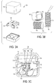
- Fig. 3A shows an exploded view of the object 104 according to the embodiment shown in Fig. 2 .
- the object 104 may include, for example, the body 108 (shown, for example, as base section 110 and top section 112), at least one receiving coil 114 (see Fig. 3B ), and a lighting element 116.
- the body 108 may include a plurality of cores 118 (see Fig. 3A ) around which separate receiving coils 114 can be wound, as shown in Fig. 3B .
- the cores 118 may be fitted into the base section 110, which may include compartments for holding and/or separating the cores 118. While Figs. 3A, 3B, and 3C depict three cores 118 and receiving coils 114, other embodiments may have fewer or more cores 118 and receiving coils 114, depending on the specific application.
- the receiving coil For simplicity, portions of the following will refer to "the receiving coil.” It should be understood, however, that embodiments of the current invention may include one or multiple receiving coils. Therefore, descriptions herein that refer to a receiving coil in the singular sense can, where appropriate, apply to any number of receiving coils that may be included in some embodiments.
- the body 108 has one or more translucent portions 120 through which light can at least partially pass.
- the translucent portion 120 may cover substantially all of the body, or only a select area or areas. In some embodiments, the entire body 108 may be made of a translucent material.
- a body 208 is made of a translucent material and is uncoated. However, the body 208 may be selectively coated with a substantially opaque coating 122, as shown in Fig. 4B .
- the translucent portions 120 of the body 108 may be left uncoated, or may be coated with a translucent coating 124.
- the translucent coating 124 may have a finish or coloring to affect the light shining through the translucent coating 124. For example, the translucent coating 124 may have a metallic appearance.
- the receiving coil 114 of the object 104 inductively receives energy from the transmitting coil 106.
- a current is induced in the receiving coil 114 and that current is used to power the lighting element 116 to produce light.
- the light can then be seen on the exterior of the light-emitting object 104 due to the translucent portions 120 of the body 106.
- the lighting element 116 emits light via a light emitting diode (LED) 126.
- the lighting element 116 includes multiple LEDs 126a, 126b, 126c, as shown in Fig. 3C , each of which may emit a different color light.
- the lighting element may include an RGB LED.
- an RGB LED is capable of producing red, green, and blue light, as well as other colors via a combination of the red, green, and blue lights. Therefore, in some embodiments, the body 108 is capable of exhibiting up to six colors of light corresponding to the three single colors of the RGB LED, as well as the three colors from combining any two of the single colors of the RGB LED. However, it is possible that differently colored LEDs or other numbers of LEDs and/or different configurations of receiving coils 114 can be provided to produce different light color combinations. Additionally, in RGB embodiments, three individual LEDs can be used in place of an RGB LED. As discussed above, the lighting element may include any number of light emitting materials, devices, or mechanisms, which may be in a variety of forms and shapes. For example, in some embodiments, the lighting element may include light sheets or flexible LED sheets, or electroluminescent wire (or EL wire), as well as other alternatives.
- the body may include two or more receiving coils 114, as well as two or more LEDs 126.
- each LED 126 may be powered by current from a separate receiving coil 114.
- the input terminals of each LED 126 can be electrically coupled to the output of one of the receiving coils.
- a given LED 126 may be configured to only generate light when the receiving coil 114 corresponding to that LED 126 has an induced current.
- the lighting element 116 therefore, may be able to produce light having a color corresponding to the light color from any single LED or light having a color corresponding to a combination of differently colored LEDs, as discussed above.
- the use of receiving coils 114 to power the lighting element 116 can eliminate the need for the object 104 to have an on board power supply, such as a battery.
- a light diffuser 128 can be disposed within the body 108.
- the light diffuser 128 is a translucent material with a dome shape, or it may be formed as a lens.
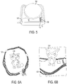
- Fig. 5 shows an example of a dome shaped diffuser 128 made of a translucent material.
- At least one of the transmitting coil 106 and the object 104 is movable with respect to the other.
- a change in a rotational orientation of the transmitting coil 106 or the object 104 alters a lighting state of the lighting element 116 in accordance with the principles of electromagnetic induction and the configuration of the receiving coil 114 within the object 104.
- the object 204 according to the embodiment in Fig. 6A has a first orientation with respect to the transmitting coil 106 and exhibits a certain lighting state.
- the object 204 has been rotated ninety degrees with respect to the transmitting coil 106 and, as a result, exhibits a different lighting state. Therefore, the lighting element 216 of object 204 and thus the light effect of the object 204 can be controlled by manipulating the orientation of the object 204 and/or the transmitting coil 106.
- each receiving coil 114 may be configured to inductively receive energy under select circumstances.
- a receiving coil 114 may be inductively matched to one or more transmitting coils 106. The higher the degree of inductance matching between transmitting coil and receiving coil, the greater the current induced in the receiving coil. Thus, the receiving coil 114 will preferentially receive energy from the matched one or more transmitting coils 106. In some embodiments, only some receiving coils 114 are sufficiently inductance matched to the transmitting coil 106 to generate light in the lighting element 116.
- each of the receiving coils 114 has a central axis 130, which may have a different orientation from the central axes 130 of the other receiving coils 114.
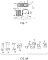
- the central axis 130 of each receiving coil 114 is substantially perpendicular to the central axis 130 of each other receiving coil 114, as shown in Fig. 7 , however, other embodiments are possible.
- the arrows show the respective directions of the central axes 130, with the axis 130 of the lower right coil 114 being into the page.
- each receiving coil 114 varies based on a relative orientation between the transmitting coil 106 and the receiving coil 114, which is within the light-emitting object 104. Therefore, by having differently oriented receiving coils 114 that are each electrically coupled to an LED 126, a relative change in orientation between the object 104 and the transmitting coil 106 will cause the object 104 to exhibit varying lighting states in which one or more of the LEDs 126 is turned on or off, or are in various states between on and off.
- Figs. 6A and 6B show an embodiment where a rotation of the object 204 with respect to the transmitting coil 106 changes the lighting state of the object 204.
- Both the first and second LEDs 126a and 126b may simultaneously emit some light during a transition from the first orientation to the second orientation of the body 108 due to a partial alignment of two receiving coils 114 with a transmitting coil 106 during the transition.
- One or more additional transmitting coils can be included, with different orientations than the first transmitting coil 106, to add additional colors or combinations of colors.
- the cores 118 can be made in different shapes and sizes to provide differently shaped or sized receiving coils 114. This can include varying the length, width, lateral cross-section, wire diameter, or wire material of a coil. In the case of multiple receiving coils, each receiving coil 114 may have the same or a different shape and size.
- Figs. 8A-8C show a variety of cores 118 of different shapes and sizes according to various embodiments. Fig. 8A shows examples of cores 118 having square or rectangular shapes, while Fig. 8B shows examples of circular cores 118. In addition, Fig. 8C shows examples of two cores 118, each shown with and without a receiving coil 114.
- a receiving coil may inductively receive energy from the second transmitting coil, in addition to the first transmitting coil.
- a given receiving coil may be specifically tuned to receive energy from only one of the first or second transmitting coils.
- the two or more transmitting coils may be fixed with respect to one another, movable with respect to one another, or a combination of the two.
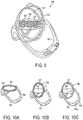
- the second transmitting coil 307 and the first transmitting coil 306 may be configured to move with respect to each other.
- the relative orientation between the two transmitting coils 306 and 307 may be varied by, for example, rotating either one of the transmitting coils 306, 307.
- the first transmitting coil 306 may be structurally connected to the field generator, and the second transmitting coil 307 may be separate from and movable with respect to the field generator.
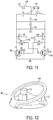
- the field generator 102 with the first transmitting coil 106 may, in some embodiments, be a free oscillator.
- Fig. 11 shows an example of a circuit board diagram for the field generator 102 according to an embodiment.
- the transmitting coil 106 can include a first inductor 134 and a second inductor 136 which are coils aligned along a common central axis and having inverse polarities.
- the field generator 102 may also include a current limit inductor 138 connected in series to the first transmitting coil 106, as well as a plurality of capacitors 140, resistors 142, and transistors 144.
- the emitting inductor and the capacitor may be value matched to generate a set frequency. Capacitors and transistors may have a high voltage value to help dissipate heat.
- the light-emitting toy assembly 100 may also include a platform to support the light-emitting objects 104.
- Fig. 12 shows a light-emitting toy assembly 400 according to an embodiment that has a platform 446 to support the objects 404.
- the first transmitting coil 406 can be integral with or connected to the platform 446.
- a second transmitting coil and/or a passive coil may also be integral with or otherwise associated with a platform 346.
- any of the first transmitting coil 106, second transmitting coil 107, and/or a passive coil may be fixed or movable relative to a platform.
- the transmitting coil may lie substantially in a first plane, but a portion of the transmitting coil may also extend out of the first plane.
- the portion may permanently extend out of the first plane, for example, by being curved or angled.
- the portion may be able to rotate or bend out of this first plane and back into the first plane.
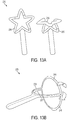
- Figs. 13A and 13B show part of a light-emitting toy assembly 200 according to an embodiment where (1) in Fig. 13A , a portion 248 of a first transmitting coil 206 can rotate out of the plane and (2) in Fig. 13B , portions 248 of both a first transmitting coil 206 and a second transmitting coil 207 can rotate out of plane.
- the portion 248 alters the electromagnetic field to affect the current induced in the receiving coils. This can produce a different lighting state in a light-emitting object as compared to when the entire transmitting coil 206 is in the first plane.
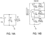
- Figs. 14A and 14B show examples of circuit board diagrams for the lighting element 116.
- Fig. 14A shows a lighting element 116 with a single LED 126 and
- Fig. 14B shows a lighting element 116 with three LEDS 126a-c.
- the lighting element 116 may include a capacitor 150 connected to each light and to the corresponding one of the receiving coils 114.
- the capacitor 150 may be used to regulate power or store energy received from the field via the receiving coil 114.
- the capacitor 150 in combination with the receiving coil 114 may act as an electrical resonator or resonant circuit for achieving a desired inductance matching between a transmitting coil and the receiving coil 114.
- the platform 346 preferably includes a plurality of spaces 358 for placement of the game pieces 304 on the platform 346.
- a game piece 304 can be positioned so that the game piece 304 rests on a space 358 on any of a number of sides of the game piece 304.
- the spaces 358 may be formed as simple markings or other demarcations on the platform 346.
- the spaces 358 are formed as indentations or holes formed on the platform 346 and in which the game pieces 304 are held.
- game pieces 304 are not limited to cubic shapes, but rather, can have any number of geometric, contoured, or irregular shapes, or combinations thereof.
- the toy assembly 300 may also include a stand 352 supporting the platform 346, Additionally, there may be a first transmitting coil 306 and a second transmitting coil 307.
- the first and second transmitting coils 306, 307 may each be rotatable with respect to the other and with respect to the platform 346.
- the first transmitting coil 306 may be rotatably mounted on the stand 352.
- the second transmitting coil 307 may have an axis of rotation that is substantially perpendicular to an axis of rotation of the first transmitting coil 306.
- the second transmitting coil 307 may be rotatably coupled to the first transmitting coil 306 and arranged concentrically with respect to the first transmitting coil 306.
- wires, other electric connections, and power sources may be located within the structural components of the toy assembly.
- the board game described above can be played in multiple variations according to different embodiments of the board game apparatus as well as different methods and rules for playing the game. Examples of some of rules according to some embodiments of the board game are described below. However, the methods of playing the game are not limited to the descriptions below.
- the method of playing this board game may include a first player taking a first turn by placing a first game piece on the platform 346.
- a first game piece can be positioned on the platform 346 before the first player places a game piece.
- a second player then takes turn by selectively doing one of the following: (1) placing a second game piece on the platform 346, or (2) rotating a game piece that is already on the platform 346 to change a lighting state of that piece.
- the second player ends that turn by rotating one of the transmitting coils 306, 307 ninety degrees. When the transmitting coil is powered to inductively transfer energy, this rotation will cause a change in the color of the light emitted by each of the game pieces 304 on the platform 346.
- This method of playing the board game is not limited to two players. Rather, the game can be played among more than two players taking successive turns.
- each player selectively rotates one of the first and second transmitting coils 306, 307 during the step of rotating one of the at least one transmitting coils 306, 307. Due to the presence of two transmitting coils, the game pieces 304 may change to one of six colors upon changing the relative rotational orientation between the game piece 304 and the transmitting coils 306, 307. Thus, more colors will appear on the platform and it may be more difficult to achieve the predetermined number and pattern of game piecing having the same color.
- the translucent portions 220 represent certain features of the doll such as the hair, eyes, stomach, or other features or body parts. Additionally, separate LEDs or lighting elements may be provided in different portions of the doll 204, as shown by the separate sets of cores 218a and 218b in the head and torso of the doll 204 in Fig. 19 .
- the at least one transmitting coil 206 and the doll 204 are relatively movable with respect to each other so that a relative position or orientation of the two can be altered to alter a lighting state of the doll. Specifically, altering a relative orientation or position can alter which, if any, of the receiving coils within the doll 204 inductively receives energy, similar to the embodiments described above.
- the toy set 200 may also include accessories 268 for the doll 204, including, for example, clothing or other items that can accompany, be worn by, or be attached to the doll 204. These accessories may also emit light when inductively receiving energy from a transmitting coil 206 in a way similar to the doll 204. For example, different receiving coils (not pictured) in the accessories 268 can be connected to corresponding LEDs 226 to emit differently colored lights or light patterns in the accessory, as shown in Fig. 17 .
- the toy set 200 may also include a timing chip (not pictured) to control an on or off state of one or more LEDs according to a timed basis.
- the timing chip may be provided within the doll 204 or electrically coupled to the accessory 268.
- the timing chip may turn off an LED that has been on for a predetermined amount of time, or may turn off an LED based on an amount of time after which the receiving coil of the LED is removed from the field of the transmitting coil.
- the timing chip may turn on an LED only after a predetermined time during which the LED is off and receiving a current.
- the timing chip may execute a series of on and off commands to achieve a pulsing light or other light sequence on a timed basis.
- the timing of the on or off state of the LED, or the pattern of the light sequence may signify an emotion of or communication by the doll.
- Each building block 404 may be magnetic to magnetically attract other building blocks 404.
- the building blocks 404 may have attachment members such as inter-locking pieces to assist in building structures with the building blocks.
- the building blocks 404 may be made of varying or uniform sizes, and are not limited to any particular size or shape. However, in an embodiment, the building blocks 404 may be cubes of approximately 25 mm on each side.
- Fig. 20 shows the light-emitting toy assembly according to a second building set embodiment.
- the building block set includes building blocks 404' of various shapes and sizes. Though not pictured in Fig. 20 , the building blocks 404' may have similar internal components as the building blocks 404 described above, enabling the building blocks 404' to emit light. In addition, the various shapes of the building blocks 404' allows for flexibility in the placement or arrangement of the light-emitting components with the blocks, including receiving coils, lighting elements, and LEDs, although such flexibility is not limited to this embodiment.
- the building blocks 404' can be stacked or connected face-to-face, as shown in the various blocks 404' of Fig. 20 .
- the transmitting coil 406' is shown supported on a support structure 452.
- the power supply unit 455 can be connected to a power receiving portion 470 of the transmitting coil 406'.
- the power receiving portion 470 may have electrical contacts 471 for making electrical contact with the electrical contacts 457 of the power supply unit 455. Accordingly, the power supply unit 455 may be used to control a current flowing in the transmitting coil 406'.
- the support structure 452 may comprise multiple support structure components 452a, 452b, 452c that are stackable or connectable to form the support structure 452.
- Fig. 23 shows a toy embodiment including a transmitting coil 406" that may have a plurality of power receiving portions 470'.
- the toy may also include a stand 452' that includes a power supply unit 455' and power button 454'.
- the transmitting coil 406" may be connected to the stand 452' and power supply unit 455' so that the transmitting coil 406" may have a current.
- the transmitting coil 406" may stand vertically out of the stand 452', but the embodiment is not limited to the arrangement shown and, for example, may be inclined with respect to the vertical or may have a different shape.
- the 23 includes a toy 474 that may contain one or more lighting elements 476a, 476b, and 476c.
- the lighting elements 476a-476c may have similar components to the light-emitting elements described above, and the toy 474 may have portions permitting light from the light-emitting elements to be emitted therefrom.
- the various embodiments of the light elements and the possible light effects discussed above may also apply to this embodiment, though those details discussed above will not be repeated here. Accordingly, the lighting elements 476a-476c may be lit from energy inductively received from the transmitting coil 406".
- Fig. 24 shows another view of the transmitting coil 406" and stand 452' shown in Fig. 23 and discussed above.
- L is the inductance
- the power or field generator may be based on inductance connecting a three point type oscillator.
- the size of receiving coils may mainly be defined by the light-emitting body itself.
- the size of the light-emitting body or block is the upper limit of a coil's diameter.
- the inductance of the coil can be readily calculated as around 2.7mHz.
- winding the receiving coil using magnet wire up to a value around 2.7mHz may achieve the highest oscillating voltage in the LC circuit to drive the LED.
- a 36 gauge magnet wire (such as copper wire) was used to wind the receiving coil, however, other gauges such as 20-60 gauge, more specifically, 30-40 gauge, are possible. This may allow space savings while having sufficient inductance.
- the length of the magnet wire can be calculated from the following experience equation: In the above equation, l is the inductance to be winded in units of mH; D is the diameter of the coil in units of cm; N is the winding circles; and L is the length of the coil. According to embodiments, l is around 2.5mH, D and L are to be defined by the blocks or other game piece's inner size, and thus N can be calculated.
Landscapes
- Engineering & Computer Science (AREA)
- Computer Networks & Wireless Communication (AREA)
- Power Engineering (AREA)
- General Engineering & Computer Science (AREA)
- Multimedia (AREA)
- Toys (AREA)
- Optical Communication System (AREA)
Description
- The present invention relates generally to an inductively powered lighting assembly and related methods. More specifically, the present invention relates to an interactive, inductively powered lighting assembly used in toys, games, and other recreational or educational apparatus, and related methods.
- Electromagnetic induction is the generation of a voltage or potential difference across a conductor when the conductor is exposed to a varying magnetic field. Recently, induction has been used in consumer products for performing wireless charging of electronic devices, such as mobile phones.
- In the realm of toys and games, conventional board games have used induction to cause a piece of the game to light up when placed on the board. However, existing induction-lighted toys and games are somewhat simplistic implementations that allow for limited or no variability or configurability with respect to the light emitted by the game piece or toy.
US 2009/184468 A1 andWO 2006/020486 each discloses a light-emitting toy assembly according to the preamble ofclaim 1. The toy assembly according toUS 2009/184468 A1 is in the form of a chess module, the toy assembly according toWO 2006/020486 comprises a doll.WO 2012/118368 discloses a building block set according to the preamble of claim 11. - A light-emitting toy assembly is provided according to
claim 1. - A building block set is provided according to claim 11.
- The foregoing aspects and other features and advantages of the invention will be apparent from the following drawings.
-
FIG. 1 shows an embodiment of a light-emitting toy assembly. -
FIG. 2 shows an embodiment of a light-emitting object of the light-emitting assembly. -
FIGS. 3A, 3B, and 3C show components of an embodiment of the light-emitting object, including inFIG. 3A , an exploded view of the object with the body, base section of the body, and cores; inFIG. 3B , receiving coils wound around the cores; and inFIG. 3C , the receiving coils and cores fitted into the base section and connected to a lighting element. -
FIGS. 4A and 4B show an embodiment of a light-emitting object in the form of a doll.FIG. 4A shows the receiving coils and lighting element within the doll, andFIG. 4B shows an example of the exterior of the doll. -
FIG. 5 shows an embodiment of a light diffuser covering a lighting element. -
FIGS. 6A and 6B show an embodiment of a light-emitting object in the form of a doll positioned, inFIG. 6A , in a first orientation with respect to a transmitting coil; and inFIG. 6B , in a second orientation with respect to the transmitting coil. -
FIG. 7 shows an embodiment of a collection of three receiving coils with different orientations. -
FIGS. 8A ,8B, and 8C show various embodiments of cores and receiving coils. -
FIG. 9 shows an embodiment of a board game including a light-emitting assembly having two transmitting coils. -
FIGS. 10A, 10B, and 10C show example positions of the transmitting coils ofFIG. 9 , in various states of rotation. -
FIG. 11 shows an embodiment of a circuit diagram for a field generator of a light-emitting assembly. -
FIG. 12 shows an embodiment of a building block set incorporating a light-emitting assembly. -
FIGS. 13A and 13B show embodiments of a transmitting coil incorporated into wands and having rotatable portions. -
FIGS. 14A and 14B show embodiments of circuit diagrams of a lighting element. -
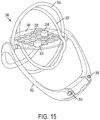
FIG. 15 shows an example of a board game including a light-emitting assembly. -
FIG. 16 shows an embodiment of a doll and play set including a light-emitting assembly. -
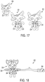
FIG. 17 shows embodiments of a doll with light-emitting clothing. -
FIG. 18 shows an embodiment of a doll and transmitting coil in the form of a wand. -
FIG. 19 is a partially exploded view of an embodiment of a doll with two sets of three cores in the interior cavity of the doll. -
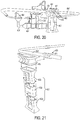
FIG. 20 shows an embodiment of a building block set incorporating a light emitting assembly. -
FIG. 21 shows a partially exploded view of an aspect of the embodiment inFIG. 20 . -
FIG. 22 shows an aspect of the embodiment shown inFIGS. 20 and 21 . -
FIG. 23 shows an embodiment of a light emitting toy assembly. -
FIG. 24 shows a transmitting coil according to the embodiment shown inFIG. 23 . -
FIG. 25 shows an aspect of the transmitting coil and a base of the embodiment shown inFIGS. 23 and24 . - Some embodiments of the current invention are discussed in detail below. In describing embodiments, specific terminology is employed for the sake of clarity. However, the invention is not intended to be limited to the specific terminology so selected. A person skilled in the relevant art will recognize that other equivalent components can be employed and other methods developed without departing from the broad concepts of the current invention. All references cited anywhere in this specification, including the Background and Detailed Description sections, are incorporated by reference as if each had been individually incorporated.
- The terms "toy" and "toy assembly" as used herein are general terms to describe a variety of embodiments of the current invention. For example, "toy" and "toy assembly" can encompass party games, board games, dolls and doll play sets, building block sets, educational toys, decorations, and novelties, and the like. However, "toy" and "toy assembly" are not limited to these examples and encompass a wide range of recreational and educational devices.
- The term "coil" refers to a wire or other conductor (e.g., a PCB) at least a portion of which has a shape that is substantially closed in a circumferential direction, such as a spiral, circle, or other geometric shape or polygon. As used herein, "coil" is not limited to a perfectly circular shape. A coil may also have a rectangular or other geometric shape, or other irregular shapes. A coil may be wound with or without a gap, and may or may be wound around an object.
- The term "translucent" refers to the physical property (or to a material or object having the physical property) of allowing light to pass through a material or object, with or without light scatting. Therefore, as used herein, a translucent material or object may include an object or material that is "transparent," i.e., allowing light to pass through a material or object without being scattered. However, a translucent material or object may also include an object that that allows light to pass through with scattering.
-
FIG. 1 shows an embodiment of a light-emittingtoy assembly 100. - The light-emitting
toy assembly 100 can include afield generator 102 and one or more light-emittingobjects 104. Thefield generator 102 can include a transmittingcoil 106 that inductively transmits energy according to the principles of electromagnetic induction. Theobject 104 can inductively receive energy from the transmittingcoil 106.Fig. 1 showsmultiple objects 104 surrounded by the transmittingcoil 106. A close-up of one of theseobjects 104 is shown inFig. 2 . Theobject 104 inFig. 2 includes anouter body 108 having abase section 110 and atop section 112, however other embodiments, includingmonolithic objects 104, are possible. -
Fig. 3A shows an exploded view of theobject 104 according to the embodiment shown inFig. 2 . Theobject 104 may include, for example, the body 108 (shown, for example, asbase section 110 and top section 112), at least one receiving coil 114 (seeFig. 3B ), and alighting element 116. Thebody 108 may include a plurality of cores 118 (seeFig. 3A ) around which separate receivingcoils 114 can be wound, as shown inFig. 3B . Thecores 118 may be fitted into thebase section 110, which may include compartments for holding and/or separating thecores 118. WhileFigs. 3A, 3B, and 3C depict threecores 118 and receivingcoils 114, other embodiments may have fewer ormore cores 118 and receivingcoils 114, depending on the specific application. - For simplicity, portions of the following will refer to "the receiving coil." It should be understood, however, that embodiments of the current invention may include one or multiple receiving coils. Therefore, descriptions herein that refer to a receiving coil in the singular sense can, where appropriate, apply to any number of receiving coils that may be included in some embodiments.
- The body of the light-emitting object can take various forms depending on the particular embodiment. In some embodiments, the body has a rectangular parallelepiped or cubic shape, such as the
body 108 shown inFigs. 1-3 . However, other shapes are possible. For example,Figs. 4A and 4B show an embodiment with abody 208 formed as adoll 204 or figurine. These and other embodiments will be discussed in further detail below. However, the form of the body is not limited to these examples, and other shapes and forms are possible. - Referring to
Fig. 4A , thebody 108 has one or moretranslucent portions 120 through which light can at least partially pass. Thetranslucent portion 120 may cover substantially all of the body, or only a select area or areas. In some embodiments, theentire body 108 may be made of a translucent material. According to an embodiment shown inFig. 4A , abody 208 is made of a translucent material and is uncoated. However, thebody 208 may be selectively coated with a substantiallyopaque coating 122, as shown inFig. 4B . Thetranslucent portions 120 of thebody 108 may be left uncoated, or may be coated with atranslucent coating 124. Thetranslucent coating 124 may have a finish or coloring to affect the light shining through thetranslucent coating 124. For example, thetranslucent coating 124 may have a metallic appearance. - According to embodiments, the receiving
coil 114 of theobject 104 inductively receives energy from the transmittingcoil 106. When inductively receiving energy, a current is induced in the receivingcoil 114 and that current is used to power thelighting element 116 to produce light. The light can then be seen on the exterior of the light-emittingobject 104 due to thetranslucent portions 120 of thebody 106. Referring toFig. 3C , thelighting element 116 emits light via a light emitting diode (LED) 126. In addition, thelighting element 116 includesmultiple LEDs Fig. 3C , each of which may emit a different color light. For example, the lighting element may include an RGB LED. An RGB LED is capable of producing red, green, and blue light, as well as other colors via a combination of the red, green, and blue lights. Therefore, in some embodiments, thebody 108 is capable of exhibiting up to six colors of light corresponding to the three single colors of the RGB LED, as well as the three colors from combining any two of the single colors of the RGB LED. However, it is possible that differently colored LEDs or other numbers of LEDs and/or different configurations of receivingcoils 114 can be provided to produce different light color combinations. Additionally, in RGB embodiments, three individual LEDs can be used in place of an RGB LED. As discussed above, the lighting element may include any number of light emitting materials, devices, or mechanisms, which may be in a variety of forms and shapes. For example, in some embodiments, the lighting element may include light sheets or flexible LED sheets, or electroluminescent wire (or EL wire), as well as other alternatives. - As discussed above, the body may include two or more receiving coils 114, as well as two or
more LEDs 126. In the case of multiple receivingcoils 114, eachLED 126 may be powered by current from aseparate receiving coil 114. For example, the input terminals of eachLED 126 can be electrically coupled to the output of one of the receiving coils. In this way, a givenLED 126 may be configured to only generate light when the receivingcoil 114 corresponding to thatLED 126 has an induced current. Thelighting element 116, therefore, may be able to produce light having a color corresponding to the light color from any single LED or light having a color corresponding to a combination of differently colored LEDs, as discussed above. According to embodiments, the use of receivingcoils 114 to power thelighting element 116 can eliminate the need for theobject 104 to have an on board power supply, such as a battery. - Referring to
Fig. 5 , to achieve a desirable outward appearance of light emitted from theobject 104, alight diffuser 128 can be disposed within thebody 108. In some embodiments, thelight diffuser 128 is a translucent material with a dome shape, or it may be formed as a lens.Fig. 5 shows an example of a dome shapeddiffuser 128 made of a translucent material. - The strength of the light may vary according to the position of the
object 104 within the electromagnetic field of thefield generator 102. As a receivingcoil 114 is positioned within a stronger portion of the electromagnetic field generated by the transmittingcoil 106, the light can become brighter. According to embodiments, the magnetic field is strongest at the center of the transmittingcoil 106, and decreases with axial distance from the center. In some embodiments, the magnetic field may be strongest near the edge of the coil (e.g., adjacent to the coil). In addition, orientation of the receivingcoil 114 with respect to the transmittingcoil 106 can vary the strength of the current induced in the receivingcoil 114, with the current being the strongest when the receivingcoil 106 is oriented perpendicular to the field lines of the electromagnetic field in the vicinity of the receiving coil, and the current being the weakest when the receivingcoil 106 is oriented parallel to the field lines of the electromagnetic field in the vicinity of the receiving coil. - At least one of the transmitting
coil 106 and theobject 104 is movable with respect to the other. A change in a rotational orientation of the transmittingcoil 106 or theobject 104 alters a lighting state of thelighting element 116 in accordance with the principles of electromagnetic induction and the configuration of the receivingcoil 114 within theobject 104. For example, theobject 204 according to the embodiment inFig. 6A has a first orientation with respect to the transmittingcoil 106 and exhibits a certain lighting state. InFig. 6B , however, theobject 204 has been rotated ninety degrees with respect to the transmittingcoil 106 and, as a result, exhibits a different lighting state. Therefore, thelighting element 216 ofobject 204 and thus the light effect of theobject 204 can be controlled by manipulating the orientation of theobject 204 and/or the transmittingcoil 106. - In order for each
LED 126 to be selectively lit by an induced current in each corresponding receivingcoil 114, each receivingcoil 114 may be configured to inductively receive energy under select circumstances. For example, a receivingcoil 114 may be inductively matched to one or more transmitting coils 106. The higher the degree of inductance matching between transmitting coil and receiving coil, the greater the current induced in the receiving coil. Thus, the receivingcoil 114 will preferentially receive energy from the matched one or more transmitting coils 106. In some embodiments, only some receivingcoils 114 are sufficiently inductance matched to the transmittingcoil 106 to generate light in thelighting element 116. - Referring to
Fig. 7 , in some embodiments, each of the receiving coils 114 has acentral axis 130, which may have a different orientation from thecentral axes 130 of the other receiving coils 114. In an embodiment, thecentral axis 130 of each receivingcoil 114 is substantially perpendicular to thecentral axis 130 of each other receivingcoil 114, as shown inFig. 7 , however, other embodiments are possible. InFig. 7 , the arrows show the respective directions of thecentral axes 130, with theaxis 130 of the lowerright coil 114 being into the page. - According to the principles of induction, the energy received by each receiving
coil 114 varies based on a relative orientation between the transmittingcoil 106 and the receivingcoil 114, which is within the light-emittingobject 104. Therefore, by having differently oriented receivingcoils 114 that are each electrically coupled to anLED 126, a relative change in orientation between theobject 104 and the transmittingcoil 106 will cause theobject 104 to exhibit varying lighting states in which one or more of theLEDs 126 is turned on or off, or are in various states between on and off. For example,Figs. 6A and 6B show an embodiment where a rotation of theobject 204 with respect to the transmittingcoil 106 changes the lighting state of theobject 204. In other words, in embodiments where eachcentral axis 130 is substantially perpendicular to the othercentral axes 130, one of the receivingcoils 114 may be parallel to a central axis 132 of a transmittingcoil 106, while the other receivingcoils 114 are at right-angles to the central axes 132 of the transmittingcoil 106. Therefore, only the receivingcoil 114 that is aligned with the transmittingcoil 106 will inductively receive energy. - As discussed further below, two perpendicular receiving coils 114 may simultaneously have an induced current and therefore their
corresponding LEDs 126 may emit light in a given orientation due to the configuration of the first and second receiving coils 114a and 114b and transmittingcoil 106. For example, both of the coils 114a, 114b can be oriented somewhere between perpendicular and parallel to the first transmitting coil causing bothLEDs 126 to emit light somewhere between "full power" and "no power," resulting in a color blend between the colors of the twoLEDs 126. This same principal can also be applied to arrangements of three ormore LEDs 126 and connected receiving coils 114. Both the first andsecond LEDs body 108 due to a partial alignment of two receivingcoils 114 with a transmittingcoil 106 during the transition. One or more additional transmitting coils can be included, with different orientations than thefirst transmitting coil 106, to add additional colors or combinations of colors. - As discussed above with respect to
Figs. 3A-3C , the light-emittingobject 104 may also include one ormore cores 118. Any of the at least one receiving coils 114 may be wound around arespective core 118. Thecore 118 may be made out of various materials, including polymer, plastic, ceramic, or metallic materials, including magnetic materials, such as iron, or any other suitable material. Magnetic cores may be used to affect (e.g., increase) the inductance. - Additionally, the
cores 118 can be made in different shapes and sizes to provide differently shaped or sized receiving coils 114. This can include varying the length, width, lateral cross-section, wire diameter, or wire material of a coil. In the case of multiple receiving coils, each receivingcoil 114 may have the same or a different shape and size.Figs. 8A-8C show a variety ofcores 118 of different shapes and sizes according to various embodiments.Fig. 8A shows examples ofcores 118 having square or rectangular shapes, whileFig. 8B shows examples ofcircular cores 118. In addition,Fig. 8C shows examples of twocores 118, each shown with and without a receivingcoil 114. - As mentioned above, the light-emitting toy assembly in some embodiments may include at least a second transmitting coil that also inductively transmits energy.
Fig. 9 shows a light-emittingtoy assembly 300 according to such an embodiment. Theassembly 300 has afirst transmitting coil 306 and asecond transmitting coil 307. The embodiment shown inFig. 9 is related to a board game, which is discussed further below. While this embodiment is shown as an example of two transmittingcoils - A receiving coil may inductively receive energy from the second transmitting coil, in addition to the first transmitting coil. Alternatively, it is possible that a given receiving coil may be specifically tuned to receive energy from only one of the first or second transmitting coils. According to embodiments, the two or more transmitting coils may be fixed with respect to one another, movable with respect to one another, or a combination of the two. For example, according to the embodiment of
Figs. 9, 10A, 10B, and 10C , thesecond transmitting coil 307 and thefirst transmitting coil 306 may be configured to move with respect to each other. Thus, the relative orientation between the two transmittingcoils first transmitting coil 306 may be structurally connected to the field generator, and thesecond transmitting coil 307 may be separate from and movable with respect to the field generator. - The light-emitting
toy assembly 100 may further include a passive coil (not pictured). While the passive coil may be of a similar construction to the transmittingcoil 106, embodiments of the passive coil may not be independently powered to form an electromagnetic field. Instead, the passive coil can inductively receive energy from one or more of the transmitting coils and, by the resulting induced current in the passive coil, reinforces or extends the electromagnetic field. Accordingly, the passive coil can extend the range within which the transmitting coils can inductively transmit energy. In the context of a block stacking game, one or more transmitting coil can be located at the base of the game, and one or more passive coils can be located at a distance above the base of the game, allowing the blocks to illuminate at a greater distance from the base then would be possible without the passive coil(s). - The
field generator 102 with thefirst transmitting coil 106 may, in some embodiments, be a free oscillator.Fig. 11 shows an example of a circuit board diagram for thefield generator 102 according to an embodiment. The transmittingcoil 106 can include afirst inductor 134 and asecond inductor 136 which are coils aligned along a common central axis and having inverse polarities. Thefield generator 102 may also include acurrent limit inductor 138 connected in series to thefirst transmitting coil 106, as well as a plurality ofcapacitors 140,resistors 142, andtransistors 144. In some embodiments, the emitting inductor and the capacitor may be value matched to generate a set frequency. Capacitors and transistors may have a high voltage value to help dissipate heat. - The light-emitting
toy assembly 100 according to some embodiments may also include a platform to support the light-emittingobjects 104. For example,Fig. 12 shows a light-emittingtoy assembly 400 according to an embodiment that has aplatform 446 to support theobjects 404. In addition, thefirst transmitting coil 406 can be integral with or connected to theplatform 446. As shown inFig. 9 , a second transmitting coil and/or a passive coil may also be integral with or otherwise associated with aplatform 346. In various embodiments, any of thefirst transmitting coil 106, second transmitting coil 107, and/or a passive coil may be fixed or movable relative to a platform. - According to some embodiments, the transmitting coil may lie substantially in a first plane, but a portion of the transmitting coil may also extend out of the first plane. For example, the portion may permanently extend out of the first plane, for example, by being curved or angled. Alternatively, the portion may be able to rotate or bend out of this first plane and back into the first plane. For example,
Figs. 13A and 13B show part of a light-emittingtoy assembly 200 according to an embodiment where (1) inFig. 13A , aportion 248 of afirst transmitting coil 206 can rotate out of the plane and (2) inFig. 13B ,portions 248 of both afirst transmitting coil 206 and asecond transmitting coil 207 can rotate out of plane. As a result, theportion 248 alters the electromagnetic field to affect the current induced in the receiving coils. This can produce a different lighting state in a light-emitting object as compared to when theentire transmitting coil 206 is in the first plane. -
Figs. 14A and 14B show examples of circuit board diagrams for thelighting element 116.Fig. 14A shows alighting element 116 with asingle LED 126 andFig. 14B shows alighting element 116 with threeLEDS 126a-c. Thelighting element 116 may include acapacitor 150 connected to each light and to the corresponding one of the receiving coils 114. Thecapacitor 150 may be used to regulate power or store energy received from the field via the receivingcoil 114. Thecapacitor 150 in combination with the receivingcoil 114 may act as an electrical resonator or resonant circuit for achieving a desired inductance matching between a transmitting coil and the receivingcoil 114. - In some embodiments, the transmitting coil may be powered by batteries, an AC power source, a DC power source, or any other suitable source of electrical power. The light-emitting toy assembly may provide a space for housing batteries used to power the transmitting coil. In embodiments where the transmitting coil may receive power from an external source, such as an AC or DC power source, the light-emitting toy assembly may not provide a space for storing batteries. Alternatively, the transmitting coil may be optionally powered by either batteries or an AC or DC power source, as desired. For example, in some embodiments, the AC or DC power source may be used to not only power the transmitting coil, but also to charge any batteries provided in the light-emitting toy assembly.
- The light-emitting toy assembly may also include a timing chip configured to turn an LED on or off on a timed basis. For example, the timing chip may execute a command to turn off one or more LEDs after those LEDs have been on for a predetermined time. Further, the timing chip may turn an LED on and off repeatedly to form a pulsing light effect or some other lighting sequence according to a timed basis. Such a timing chip may be associated with one or more individual LEDs. Alternatively, the timing chip may be associated with the transmitting coil to turn on or off the transmitting coil in order to affect (e.g., turn on or off) one or more LEDs.
-
Fig. 15 shows a light-emittingtoy assembly 300 according to an example board game embodiment. Theassembly 300 can include aplatform 346, at least one transmittingcoil 306, and a plurality ofgame pieces 304. The transmittingcoil 306 may be positioned substantially around theplatform 346 and can generate an electromagnetic field to inductively transfer energy. Thegame pieces 304 may be positioned on theplatform 346, and each of thegame pieces 304 can include a body 308, at least one receiving coil 314, and a lighting element 316. - The
platform 346 preferably includes a plurality ofspaces 358 for placement of thegame pieces 304 on theplatform 346. Agame piece 304 can be positioned so that thegame piece 304 rests on aspace 358 on any of a number of sides of thegame piece 304. Thespaces 358 may be formed as simple markings or other demarcations on theplatform 346. In some embodiments, thespaces 358 are formed as indentations or holes formed on theplatform 346 and in which thegame pieces 304 are held. One of ordinary skill in the art will understand based on this disclosure, thatgame pieces 304 are not limited to cubic shapes, but rather, can have any number of geometric, contoured, or irregular shapes, or combinations thereof. Each game piece can have a construction similar to theobject 104 shown inFigs. 1-3C and discussed above. Accordingly, for the sake of brevity, the various components and possible embodiments of the light-emittingobject 102 discussed above will not be repeated here with respect to thegame pieces 304. - The
toy assembly 300 may also include astand 352 supporting theplatform 346, Additionally, there may be afirst transmitting coil 306 and asecond transmitting coil 307. The first and second transmitting coils 306, 307 may each be rotatable with respect to the other and with respect to theplatform 346. For example, thefirst transmitting coil 306 may be rotatably mounted on thestand 352. Thesecond transmitting coil 307 may have an axis of rotation that is substantially perpendicular to an axis of rotation of thefirst transmitting coil 306. As shown inFig. 10 , thesecond transmitting coil 307 may be rotatably coupled to thefirst transmitting coil 306 and arranged concentrically with respect to thefirst transmitting coil 306. As will be appreciated by one of ordinary skill in the art, wires, other electric connections, and power sources may be located within the structural components of the toy assembly. - The
game piece 304 can exhibit various lighting states due to the inclusion of two or more LEDs and corresponding receiving coils. These lighting states can be altered to exhibit various colors by manipulating the orientation of thegame piece 304 while positioned on theplatform 346. The lighting state may also be changed by altering the orientation of the transmittingcoils Fig. 10 . - For example, when one of the
game pieces 304 is positioned on theplatform 346, it can be oriented such that at least one receiving coil within the game piece 314 is inductively receiving energy. If thegame piece 304 is then, for example, rotated by substantially ninety degrees to rest on an adjacent face of thegame piece 304, a different receiving coil within thegame piece 304 will inductively receive energy. Therefore, whether an LED of thegame piece 304 is lit will depend at least, for example, on the rotational orientation of thegame piece 304. As discussed above, a similar change in light emitted from thegame piece 304 can be achieved by changing the relative position of thegame piece 304 within the field by moving the transmittingcoil 306 and/or 307 with respect to theplatform 346 on which thegame piece 304 sits. - As discussed above, the lighting element 316 may emit light from differently colored LEDs, or a single, multi-color LED such as a RGB LED. When LEDs of three different colors are included in the
game piece 304, thegame piece 304 may exhibit up to six different colors from one or a combination of the three different colors based on a relative rotational orientation between the at least one transmitting coil 314 and thegame piece 304. - The transmitting
coil 306 and/or transmittingcoil 307 can be connected to circuitry housed in thestand 352 and/orplatform 346. Theassembly 300 may be selectively powered on and off by a player via a button, switch, or other input mechanism on the exterior of thestand 352,platform 346, or other part of theassembly 300.Figs. 9 and15 show embodiments with input mechanisms in the form ofbuttons 354 that may be provided at the base of thestand 352. In a two-button configuration, onebutton 354a can be used to selectively power thefirst transmitting coil 306 and theother button 354b can selectively power thesecond transmitting coil 307. In other embodiments, only asingle button 354 may be provided for selectively powering all transmittingcoils stand 352, or by a DC power supply connected to apower input 356 on thestand 352, for example, from a household AC transformer. - The board game described above can be played in multiple variations according to different embodiments of the board game apparatus as well as different methods and rules for playing the game. Examples of some of rules according to some embodiments of the board game are described below. However, the methods of playing the game are not limited to the descriptions below.
- A board game can be played on the
board game assembly 300 described above, which includes aplatform 346 having at least one transmittingcoil 306 that is positioned substantially around theplatform 346 and that is configured to inductively transfer energy to a plurality ofgame pieces 304. Eachgame piece 304 emits light of a plurality of colors when inductively receiving energy from the transmittingcoil 306, and the light emitted has a color that depends on a relative rotational orientation between thegame piece 304 and the one or more transmitting coils 306. - The method of playing this board game may include a first player taking a first turn by placing a first game piece on the
platform 346. Alternatively, a first game piece can be positioned on theplatform 346 before the first player places a game piece. A second player then takes turn by selectively doing one of the following: (1) placing a second game piece on theplatform 346, or (2) rotating a game piece that is already on theplatform 346 to change a lighting state of that piece. After performing one of these actions, the second player ends that turn by rotating one of the transmitting coils 306, 307 ninety degrees. When the transmitting coil is powered to inductively transfer energy, this rotation will cause a change in the color of the light emitted by each of thegame pieces 304 on theplatform 346. - Game play proceeds by each player taking successive turns to perform the above-described actions of the second player. Namely, each successive player may either (1) place another game piece on the platform, or (2) rotate a game piece that is already on the platform. That player then ends his or her turn by rotating one of the transmitting coils 306, 307 ninety degrees to change the color of the light emitted by the game pieces on the
platform 346. The game is won by a single player when, at the end of the winning player's turn, a predetermined number of game pieces having the same color are arranged in a predetermined pattern. The number of game pieces can be, for example, 4 or 5, or some other number, which can be adjusted to vary the difficulty of the game. The predetermined pattern can be, for example, a line running vertically, horizontally, or diagonally across theplatform 346. - This method of playing the board game is not limited to two players. Rather, the game can be played among more than two players taking successive turns.
- The difficult of the game can be altered by changing a number of transmitting
coils first transmitting coil 306 may be used to inductively transfer energy. In this case, each player may only rotate thefirst transmitting coil 306 during each step of rotating one of the at least one transmitting coils. With only one transmitting coil transmitting energy, if eachgame piece 304 has only three different colored lights, thegame piece 304 can change to one of three colors upon changing the relative rotational orientation between thegame piece 304 and thefirst transmitting coil 306. In a more difficult level of game play, both thefirst transmitting coil 306 and thesecond transmitting coil 307 inductively transfer energy. In this more difficult case, each player selectively rotates one of the first and second transmitting coils 306, 307 during the step of rotating one of the at least one transmitting coils 306, 307. Due to the presence of two transmitting coils, thegame pieces 304 may change to one of six colors upon changing the relative rotational orientation between thegame piece 304 and the transmitting coils 306, 307. Thus, more colors will appear on the platform and it may be more difficult to achieve the predetermined number and pattern of game piecing having the same color. - As discussed above, a light-emitting
toy assembly 200 according to some embodiments may comprise a toy set including a light-emitting doll or figurine and various play sets and/or accessories for the doll.Figs. 16-19 show a light-emitting toy assembly according to this embodiment. Examples of this embodiment are also shown inFig. 4 ,6 , and13 , which were discussed above. The toy set 200 ofFig. 16 can include a field generator 202 including at least one transmittingcoil 206 to inductively transmit energy. The toy set 200 can also include aplatform 246 for supporting one or more of the dolls. Thedoll 204 has an exterior of which at least aportion 220 is translucent. As shown inFig. 19 , the exterior confines aninterior cavity 260. Within thecavity 260 are at least one receiving coil (not pictured) to inductively receive energy from the at least one transmittingcoil 206. For clarity,Fig. 19 showscores 218 without the receiving coils. The lighting element is also not pictured inFig 19 , but an embodiment of thelighting element 216 attached to a set of receiving coils 214 can be seen inFig. 4A . - In some embodiments, the
translucent portions 220 represent certain features of the doll such as the hair, eyes, stomach, or other features or body parts. Additionally, separate LEDs or lighting elements may be provided in different portions of thedoll 204, as shown by the separate sets of cores 218a and 218b in the head and torso of thedoll 204 inFig. 19 . - The at least one transmitting
coil 206 and thedoll 204 are relatively movable with respect to each other so that a relative position or orientation of the two can be altered to alter a lighting state of the doll. Specifically, altering a relative orientation or position can alter which, if any, of the receiving coils within thedoll 204 inductively receives energy, similar to the embodiments described above. -
Fig. 18 shows an embodiment where the field generator 202 resembles awand 262 that can be held by ahandle portion 264 so that a transmittingcoil 206 disposed on the end of thewand 262 is positioned near thedoll 204 to inductively transmit energy to thedoll 204.Fig. 13 , which was discussed above, shows examples of embodiments where aportion 248 of the transmittingcoil 206 is rotatable into a second plane. The transmitting coil can transmit energy to one or more receiving coils in thedoll 204 to illuminate one or more corresponding lighting elements in thedoll 204. - As mentioned above, the field generator 202 may also include a
platform 246 to support thedoll 204. The transmittingcoil 206 may be located in or under theplatform 246, or may be positioned above or around theplatform 246. For example, at least a part of the transmittingcoil 206 may form an arch 266 over theplatform 246, as shown inFig. 16 . The transmittingcoil 206 is optionally rotatable with respect to theplatform 246 so that thedoll 204 can be placed on theplatform 246 while the transmittingcoil 206 is rotated with respect to thedoll 204. In an embodiment, the arch 266 can be rotated as indicated by the arrow inFig. 16 . - A particular receiving coil in a
doll 204 may be tuned or inductively matched to only inductively receive energy from one or more particular transmitting coils, but not to receive energy from other transmitting coils. Therefore, thedoll 204 can light up with the color of the LED corresponding to those particular receiving coils only when in the field of those particular transmitting coils. In this way, an interactive toy experience is provided where the doll must be matched to certain settings, accessories, or wands to exhibit a certain light color. - As shown in
Figs. 17 and 18 , the toy set 200 may also includeaccessories 268 for thedoll 204, including, for example, clothing or other items that can accompany, be worn by, or be attached to thedoll 204. These accessories may also emit light when inductively receiving energy from a transmittingcoil 206 in a way similar to thedoll 204. For example, different receiving coils (not pictured) in theaccessories 268 can be connected to correspondingLEDs 226 to emit differently colored lights or light patterns in the accessory, as shown inFig. 17 . - In some embodiments, the toy set 200 may also include a timing chip (not pictured) to control an on or off state of one or more LEDs according to a timed basis. The timing chip may be provided within the
doll 204 or electrically coupled to theaccessory 268. The timing chip may turn off an LED that has been on for a predetermined amount of time, or may turn off an LED based on an amount of time after which the receiving coil of the LED is removed from the field of the transmitting coil. Alternatively, the timing chip may turn on an LED only after a predetermined time during which the LED is off and receiving a current. Further, the timing chip may execute a series of on and off commands to achieve a pulsing light or other light sequence on a timed basis. In some embodiments, the timing of the on or off state of the LED, or the pattern of the light sequence may signify an emotion of or communication by the doll. -
Fig. 12 shows the light-emitting toy assembly according to a building set embodiment. The building block set 400 can include at least one transmittingcoil 406 to inductively transmit energy to a plurality ofbuilding blocks 404, similar to aspects of the above described embodiments. The plurality ofbuilding blocks 404 may have a construction similar to aspects of theobjects 104 orgame pieces 304 described above. For brevity, those aspects will not be repeated here in full. Theset 400 also includes aplatform 446 to support the building blocks 404. The transmittingcoil 406 inFig. 12 is rotatably attached to theplatform 446. For example, the transmittingcoil 406 may rotate from a first position where it is substantially parallel to theplatform 446, to a second position where it is substantially perpendicular to theplatform 446. In this way, the relative orientation of the transmittingcoil 406 and thebuilding blocks 404 on theplatform 446 can be altered to affect the lighting state of theblocks 404. Additionally, theset 400 is not limited to one transmitting coil, but may have multiple transmitting coils. - Each
building block 404 may be magnetic to magnetically attractother building blocks 404. In some embodiments, thebuilding blocks 404 may have attachment members such as inter-locking pieces to assist in building structures with the building blocks. Thebuilding blocks 404 may be made of varying or uniform sizes, and are not limited to any particular size or shape. However, in an embodiment, thebuilding blocks 404 may be cubes of approximately 25 mm on each side. -
Fig. 20 shows the light-emitting toy assembly according to a second building set embodiment. The building block set includes building blocks 404' of various shapes and sizes. Though not pictured inFig. 20 , the building blocks 404' may have similar internal components as thebuilding blocks 404 described above, enabling the building blocks 404' to emit light. In addition, the various shapes of the building blocks 404' allows for flexibility in the placement or arrangement of the light-emitting components with the blocks, including receiving coils, lighting elements, and LEDs, although such flexibility is not limited to this embodiment. The building blocks 404' can be stacked or connected face-to-face, as shown in the various blocks 404' ofFig. 20 . The transmitting coil 406' is shown supported on asupport structure 452. Thesupport structure 452 shown inFig. 20 is just one example of a support structure for the receiving coil, but is not limited to the embodiment shown. Apower supply unit 455 may be supplied on top of thesupport structure 452, and may havegripping portions 453, apower button 454, andelectrical contacts 457. - As shown in
Fig. 21 , thepower supply unit 455 can be connected to apower receiving portion 470 of the transmitting coil 406'. Thepower receiving portion 470 may haveelectrical contacts 471 for making electrical contact with theelectrical contacts 457 of thepower supply unit 455. Accordingly, thepower supply unit 455 may be used to control a current flowing in the transmitting coil 406'. Thesupport structure 452 may comprise multiplesupport structure components support structure 452. - In some embodiments, the
power supply unit 455 may supply power via a battery, or AC or DC power source. Alternatively, thepower supply unit 455 may merely operate as a switch to open and/or close a current flow path around the transmitting coil 406'. In either case, thepower button 454 may be operated to start and stop a current flow in the transmitting coil 406'. Multiplepower receiving portions 470 may be supplied around the transmitting coil 406'. -
Fig. 22 shows a close-up of thepower supply unit 455, which may have, for example, threeelectrical contacts 457. The grippingportions 453 may be formed as a partial ring shape, for example, a partial torus shape, that corresponds to a shape of a part of thepower receiving portion 470 of the transmitting coil 406'. Accordingly, thepower supply unit 455 may be attached to thepower receiving portion 470. The grippingportions 453 may be configured to allow for easy removable and re-attachment of thepower supply unit 455 to one or morepower receiving portions 470. -
Fig. 23 shows a toy embodiment including a transmittingcoil 406" that may have a plurality of power receiving portions 470'. The toy may also include a stand 452' that includes a power supply unit 455' and power button 454'. The transmittingcoil 406" may be connected to the stand 452' and power supply unit 455' so that the transmittingcoil 406" may have a current. As shown inFig. 23 , the transmittingcoil 406" may stand vertically out of the stand 452', but the embodiment is not limited to the arrangement shown and, for example, may be inclined with respect to the vertical or may have a different shape. The example shown inFig. 23 includes atoy 474 that may contain one ormore lighting elements lighting elements 476a-476c may have similar components to the light-emitting elements described above, and thetoy 474 may have portions permitting light from the light-emitting elements to be emitted therefrom. The various embodiments of the light elements and the possible light effects discussed above may also apply to this embodiment, though those details discussed above will not be repeated here. Accordingly, thelighting elements 476a-476c may be lit from energy inductively received from the transmittingcoil 406". -
Fig. 24 shows another view of the transmittingcoil 406" and stand 452' shown inFig. 23 and discussed above. -
Fig. 25 shows a close-up of the power supply unit 455' and stand 452'. The power receiving portion 470' of the transmittingcoil 406" is connected to the power supply unit 455' in such a way that the power button 454' can be operated to turn on or off the transmittingcoil 406". - The following are examples of design of circuits used in some embodiments. These are meant to be examples only.
- The generated voltage in an inductor is:

- L is the inductance, i is current through the inductor. This equation means higher current or higher inductance can generate higher voltage at two terminals of the inductor. Because a sine wave is applied in the circuit, then i = Asinωt, where A is the amplitude of the current and ωis the frequency of the current. The voltage equation can be rewritten as:

- This means the voltage is a function of inductance, amplitude and frequency of the current. From this, the following guidelines apply to some of the embodiments of the current invention.
- First, the current through the circuit might be as high as, for example, 100mA-150mA, depending on the components used in a given embodiment. If the current is too high, excess heat can be generated which can negatively impact performance or degrade the components such as the resistors or capacitors. Second, inductance is limited by the volume of the inductor. Higher inductance can prevent higher frequency current from getting through. Third, with current of, for example, 100mA, and inductance limited, the only other parameter that can be changed is the frequency. However, too high of a frequency will not pass through the inductor. Some embodiments use a frequency of between about 50 and 150 KHz, more particularly, between about 75 and 125 KHz, such as about 100KHz.
- The power or field generator (oscillating circuit) may be based on inductance connecting a three point type oscillator. The frequency of the oscillating circuit can be calculated based on:

- In the above equation, L is the total inductance of all coils. For example, when there are two coils in the circuit, the total inductance can be calculated as L=L1+L2+M, where M is the mutual inductance between L1 and L2. With the frequency in the circuit being, for example, 100KHz, and the capacitor being predefined as 47nF, the inductance of each coil can be readily computed as approximately L1=L2=8.6uH. This means if we choose a capacitor of 47nF, wiring 2 coils with inductance of about 8.5uH, we will get about 100KHz frequency current through the oscillator as a power or field generator for the small coils.
- The larger the volume of the coil, the bigger energy it will absorb from the magnetic field generated by the oscillating circuit inductor, and the brighter the LED could be. Practically, the size of receiving coils may mainly be defined by the light-emitting body itself. In other words, the size of the light-emitting body or block is the upper limit of a coil's diameter. In the case of using a simple LC oscillator to acquire energy for the receiving coil, the frequency equation of the LC oscillator is

- Therefore, if the frequency is 100Khz, as discussed above, and the capacitor value is selected to be 820nF, then the inductance of the coil can be readily calculated as around 2.7mHz. Thus, winding the receiving coil using magnet wire up to a value around 2.7mHz may achieve the highest oscillating voltage in the LC circuit to drive the LED.
- In some embodiments, a 36 gauge magnet wire (such as copper wire) was used to wind the receiving coil, however, other gauges such as 20-60 gauge, more specifically, 30-40 gauge, are possible. This may allow space savings while having sufficient inductance. The length of the magnet wire can be calculated from the following experience equation:
In the above equation, l is the inductance to be winded in units of mH; D is the diameter of the coil in units of cm; N is the winding circles; and L is the length of the coil. According to embodiments, l is around 2.5mH, D and L are to be defined by the blocks or other game piece's inner size, and thus N can be calculated. - The embodiments illustrated and discussed in this specification are intended only to teach those skilled in the art the best way known to the inventors to make and use the invention. Nothing in this specification should be considered as limiting the scope of the present invention. All examples presented are representative and non-limiting. The scope of the invention is defined by the appended claims.
Claims (15)
- A light-emitting toy assembly (100), comprising:a field generator (102) that includes a first transmitting coil (106, 306) configured to inductively transmit energy; andan object (104) that includes:a body (108), at least a part (120) of which is translucent;at least one receiving coil (114) being configured to inductively receive energy from the first transmitting coil (106), anda lighting element having at least one light emitting diode (126) that is configured to receive a current from a corresponding one of the at least one receiving coils (114),wherein at least one of the first transmitting coil (106) and the object (104) is movable with respect to the other of the first transmitting coil (106) and the object (104), anda change in a rotational orientation of at least one of the first transmitting coil (106) and the object (104) alters a lighting state of the lighting element,characterized in that:the at least one receiving coil (114) comprises two or more receiving coils (114), andthe at least one light emitting diode (126) comprises two or more light emitting diodes (126), each of the two or more light emitting diodes (126) being connected to a different one of the two or more receiving coils (114).
- The light-emitting toy assembly of claim 1, wherein energy received by the at least one receiving coil (114) varies based on a relative orientation between the first transmitting coil (106) and the object (104).
- The toy assembly of claim 1, further comprising a plurality of lighting elements,
wherein each of the plurality of lighting elements comprises light emitting diodes. - The light-emitting toy assembly of claim 1, wherein a central axis (130) of a first receiving coil (114) is substantially perpendicular to a central axis (130) of a second receiving coil (114).
- The light-emitting toy assembly of claim 1, further comprising:
a second transmitting coil (307) configured to inductively transmit energy, wherein the at least one receiving coil (114) is further configured to inductively receive energy from the second transmitting coil (307). - The light-emitting toy assembly of claim 5, wherein a relative orientation between the second transmitting coil (307) and the first transmitting coil (306) is variable.
- The light-emitting toy assembly of claim 5, wherein the at least one receiving coil (114) of the object (104) is configured to inductively match with the first transmitting coil (306) and is configured not to inductively match with the second transmitting coil (307).
- The light-emitting toy assembly of claim 7, wherein the at least one receiving coil (114) of the object (104) is configured to inductively match with the second transmitting coil (307) and is configured not to inductively match with the first transmitting coil (306).
- The light-emitting toy assembly of claim 1, further comprising:a passive coil configured to have a current induced by the first transmitting coil (106),wherein the current induced in the passive coil expands a field of electromagnetic energy of the assembly to increase a range in which energy can be inductively transmitted to the at least one receiving coil (114).
- The light-emitting toy assembly of claim 1, wherein the first transmitting coil (106) includes a first inductor (134) and a second inductor (136), the first inductor (134) and the second inductor (136) being coils aligned along a common central axis (134) and having inverse polarities.
- A building block set comprising:a field generator (102) that includes at least one transmitting coil (106) configured to inductively transmit energy;a plurality of building blocks (404), each building block (404) having an outer surface, and having an interior cavity containing:at least one receiving coil (114) configured to inductively receive energy from the at least one transmitting coil (106), anda lighting element including at least one light emitting diode (126), each of the at least one light emitting diodes (126) being configured to receive a current from a corresponding one of the at least one receiving coils (114),wherein at least one of the first transmitting coil (106) and at least one of the plurality of building blocks (404) is movable with respect to the other of the first transmitting coil (106) and the at least one of the plurality of building blocks (404),wherein a change in a rotational orientation of the at least one receiving coil (114) relative to the transmitting coil (106) alters a lighting state of the lighting element; anda platform (446) configured to support the plurality of building blocks (404),characterized in that
at least a portion of the outer surface of each building block (404) is translucent,the at least one receiving coil (114) comprises two or more receiving coils (114), and
the at least one light emitting diode (126) comprises two or more light emitting diodes (126), each of the two or more light emitting diodes (126) being connected to a different one of the two or more receiving coils (114). - The light-emitting toy assembly of claim 1, wherein the object (104) further comprises at least one core (118) around which a corresponding one of the plurality of receiving coils (114) is wound.
- The light-emitting toy assembly of claim 12, wherein the at least one core (118) is magnetic.
- The light-emitting toy assembly of claim 1, wherein the first transmitting coil (114) lies substantially in a first plane, and wherein a portion of the first transmitting coil (114) extends out of the first plane.
- The light-emitting toy assembly of claim 1, further comprising a plurality of receiving coils (114),
wherein each of the plurality of receiving coils (114) has a different construction.
Applications Claiming Priority (2)
| Application Number | Priority Date | Filing Date | Title |
|---|---|---|---|
| US14/246,353 US9061216B1 (en) | 2014-04-07 | 2014-04-07 | Induction light toy and related methods |
| PCT/US2015/024708 WO2015157279A2 (en) | 2014-04-07 | 2015-04-07 | Induction light toy and related methods |
Publications (2)
| Publication Number | Publication Date |
|---|---|
| EP3129109A2 EP3129109A2 (en) | 2017-02-15 |
| EP3129109B1 true EP3129109B1 (en) | 2020-06-10 |
Family
ID=53053080
Family Applications (1)
| Application Number | Title | Priority Date | Filing Date |
|---|---|---|---|
| EP15720826.5A Not-in-force EP3129109B1 (en) | 2014-04-07 | 2015-04-07 | Induction light toy and related methods |
Country Status (3)
| Country | Link |
|---|---|
| US (2) | US9061216B1 (en) |
| EP (1) | EP3129109B1 (en) |
| WO (1) | WO2015157279A2 (en) |
Families Citing this family (11)
| Publication number | Priority date | Publication date | Assignee | Title |
|---|---|---|---|---|
| US20150042223A1 (en) * | 2013-08-12 | 2015-02-12 | Daniel P. Harrington | Inductively coupled led lighting system |
| US10058790B2 (en) * | 2014-03-24 | 2018-08-28 | Bose Corporation | Motor assembly kit |
| US9981195B2 (en) * | 2016-07-18 | 2018-05-29 | Proto.Toys, Inc. | Three dimensional illumination toy |
| WO2019028364A1 (en) * | 2017-08-03 | 2019-02-07 | Laser Pegs Ventures, Llc | Lighted toy figurines and related systems and methods |
| US10951064B2 (en) * | 2018-02-28 | 2021-03-16 | Massachusetts Institute Of Technology | Coreless power transformer |
| US11280485B2 (en) * | 2018-10-22 | 2022-03-22 | Nicholas Paris | Interactive device having modular illuminated components |
| WO2020156721A1 (en) * | 2019-01-31 | 2020-08-06 | Lego A/S | Toy system having a contactless energy transfer system |
| US11857890B2 (en) | 2019-03-22 | 2024-01-02 | Lego A/S | Rechargeable interactive toy |
| US12090409B2 (en) * | 2019-04-01 | 2024-09-17 | National Entertainment Collectibles Association, Inc. | Game tile system |
| IT202100026981A1 (en) * | 2021-10-20 | 2023-04-20 | Riccardo Rontini | ELECTRIC LIGHTING DEVICE |
| US12440777B2 (en) * | 2023-06-09 | 2025-10-14 | Leo Digital (Hong Kong) Company Limited | Wirelessly powered modular toy |
Family Cites Families (41)
| Publication number | Priority date | Publication date | Assignee | Title |
|---|---|---|---|---|
| US3984109A (en) * | 1975-08-20 | 1976-10-05 | Lawrence Peska Associates, Inc. | Lighted chess game |
| US5158492A (en) | 1991-04-15 | 1992-10-27 | Elliott A. Rudell | Light activated doll |
| US5197741A (en) * | 1992-05-19 | 1993-03-30 | Wu Liung M | Electrically lightable chess piece |
| US5251904A (en) * | 1992-08-24 | 1993-10-12 | Cruz Jose A | Board game apparatus |
| WO1997013563A1 (en) | 1995-10-10 | 1997-04-17 | Durand (Assignees) Limited | Game board with light directing means |
| US6967448B2 (en) | 1997-08-26 | 2005-11-22 | Color Kinetics, Incorporated | Methods and apparatus for controlling illumination |
| US6016038A (en) | 1997-08-26 | 2000-01-18 | Color Kinetics, Inc. | Multicolored LED lighting method and apparatus |
| US6389318B1 (en) | 1998-07-06 | 2002-05-14 | Abiomed, Inc. | Magnetic shield for primary coil of transcutaneous energy transfer device |
| GB2344257A (en) * | 1998-11-26 | 2000-05-31 | Innovision Research And Techno | Data communication apparatus and board game |
| US7500917B2 (en) | 2000-02-22 | 2009-03-10 | Creative Kingdoms, Llc | Magical wand and interactive play experience |
| DE10024648A1 (en) * | 2000-05-18 | 2001-11-22 | Ulf Tiemens | Device for supplying toys with electrical energy, preferably to produce light has an air-core coil in which a low frequency magnetic alternating field is produced using a generator |
| US6325690B1 (en) * | 2000-07-06 | 2001-12-04 | Webb Nelson | Toy top with message display and associated method of initiating and synchronizing the display |
| TW502264B (en) * | 2000-08-26 | 2002-09-11 | Samsung Electronics Co Ltd | RF matching unit |
| US6647325B2 (en) * | 2001-02-19 | 2003-11-11 | Kokusan Denki Co., Ltd. | Control system for electric motor for driving electric vehicle |
| CN2467144Y (en) * | 2001-03-08 | 2001-12-26 | 南京市四方中心小学 | Electronic swing & changing colour ball |
| FR2848871B1 (en) * | 2002-12-18 | 2009-09-18 | Sylvius | ELEMENT FOR GAME, SUCH AS A PION, AND ASSOCIATED GAME SYSTEM |
| US6937152B2 (en) | 2003-04-08 | 2005-08-30 | Shoot The Moon Products Ii, Llc | Wireless interactive doll-houses and playsets therefor |
| US7361073B2 (en) * | 2004-08-10 | 2008-04-22 | Mattel, Inc. | Motion responsive toy |
| US7255624B2 (en) | 2004-10-15 | 2007-08-14 | Mega Brands America, Inc. | Illuminated, three-dimensional modules for a magnetic toy construction kit |
| US20060084357A1 (en) | 2004-10-15 | 2006-04-20 | Rosen Lawrence I | Illuminated toy construction kit |
| US7361074B1 (en) * | 2005-02-18 | 2008-04-22 | Rapid Pro Manufacturing, Martin And Periman Partnership | Rotating light toy |
| US7321284B2 (en) * | 2006-01-31 | 2008-01-22 | Tdk Corporation | Miniature thin-film bandpass filter |
| US20070184722A1 (en) * | 2006-02-07 | 2007-08-09 | Dynatech Action, Inc. | Powered modular building block toy |
| US8177601B2 (en) | 2006-11-01 | 2012-05-15 | Penny Ekstein-Lieberman | Peek-a-boo doll with dual activation |
| US20090036952A1 (en) | 2007-07-30 | 2009-02-05 | National Yang-Ming University | Induction driven light module and use thereof |
| US7731558B2 (en) | 2007-08-15 | 2010-06-08 | Jon Capriola | Illuminated toy building structures |
| US20090053971A1 (en) | 2007-08-21 | 2009-02-26 | Man Kit Hui | Interactive Doll |
| US7812562B2 (en) * | 2008-01-03 | 2010-10-12 | Visteon Global Technologies, Inc. | Method and apparatus for high speed stepper motor stall detection |
| US20090184468A1 (en) | 2008-01-17 | 2009-07-23 | Hsien-Jung Huang | Electrical chess module |
| US8602857B2 (en) * | 2008-06-03 | 2013-12-10 | Tweedletech, Llc | Intelligent board game system with visual marker based game object tracking and identification |
| KR101088974B1 (en) | 2008-06-25 | 2011-12-01 | 파나소닉 전공 주식회사 | Electrodeless discharge lamp lighting device and lighting equipment |
| KR100939166B1 (en) * | 2008-07-24 | 2010-01-28 | 신필순 | Device for playing block and method for operating the same |
| EP2352219B1 (en) * | 2008-11-17 | 2017-06-07 | Olympus Corporation | Wireless power feeder, power transmission coil unit, and wireless power feeder system |
| CN201332374Y (en) * | 2008-12-31 | 2009-10-21 | 王晓冰 | Magnetic suspension device |
| ES2615203T3 (en) | 2010-08-18 | 2017-06-05 | Capriola Corporation | System and methods for building an illuminated toy |
| RU2475290C1 (en) * | 2010-11-17 | 2013-02-20 | Общество С Ограниченной Ответственностью "Айтэм Мультимедиа" | Device for games |
| US8531048B2 (en) * | 2010-11-19 | 2013-09-10 | Gulfstream, Inc. | Light kit in combination with a pump system |
| NL1038619C2 (en) * | 2011-02-28 | 2012-08-29 | Wesselingh | A game. |
| US8393906B2 (en) | 2011-04-27 | 2013-03-12 | Genie Toys Plc | Interactive doll with toy accessories |
| WO2012177953A1 (en) | 2011-06-21 | 2012-12-27 | Jonathan Capriola | Powered toy building structures and related devices and methods |
| US8841845B2 (en) * | 2012-07-24 | 2014-09-23 | Ricardo Montemayor | Proximity-based wireless lighting system |
-
2014
- 2014-04-07 US US14/246,353 patent/US9061216B1/en active Active
-
2015
- 2015-04-07 WO PCT/US2015/024708 patent/WO2015157279A2/en not_active Ceased
- 2015-04-07 EP EP15720826.5A patent/EP3129109B1/en not_active Not-in-force
- 2015-04-13 US US14/685,562 patent/US9814992B2/en active Active
Non-Patent Citations (1)
| Title |
|---|
| None * |
Also Published As
| Publication number | Publication date |
|---|---|
| US20150283470A1 (en) | 2015-10-08 |
| US9061216B1 (en) | 2015-06-23 |
| US9814992B2 (en) | 2017-11-14 |
| WO2015157279A2 (en) | 2015-10-15 |
| WO2015157279A3 (en) | 2015-11-26 |
| EP3129109A2 (en) | 2017-02-15 |
Similar Documents
| Publication | Publication Date | Title |
|---|---|---|
| US9814992B2 (en) | Induction light toy and related methods | |
| US7361074B1 (en) | Rotating light toy | |
| US12021394B2 (en) | Toy system having a contactless energy transfer system | |
| CA2810378C (en) | Improved tethered led illuminated ball | |
| US9155958B2 (en) | Die for use in game play | |
| CN113613749A (en) | Rechargeable interactive toy | |
| KR200476042Y1 (en) | luminous stick | |
| US20180154233A1 (en) | Illuminated toss game system | |
| US11400361B2 (en) | Electrified game piece manipulation game and game piece manipulator | |
| KR102769134B1 (en) | Tumbling toy and board game tool including the same | |
| CN104180274B (en) | A kind of colored photosphere system based on controlled in wireless | |
| JP2003181159A (en) | Image display toys | |
| KR100709665B1 (en) | Yu Yong Yong | |
| JP2004230034A (en) | Rotating toy | |
| JP2008142143A (en) | Game device set and lighting device | |
| US12251639B2 (en) | Electrified game piece manipulation game and game piece manipulator | |
| US20240181334A1 (en) | Board game set | |
| KR200428081Y1 (en) | Functional 윷 | |
| CN219533898U (en) | Teaching aid | |
| JP2005071867A (en) | Illumination equipment | |
| KR200404047Y1 (en) | light system and sound have multi funny stone | |
| KR200416520Y1 (en) | Yu Yong Yong | |
| JP4445786B2 (en) | Game medium storage box and game medium storage box light emission effect system | |
| JP3181968U (en) | Luminous confectionery | |
| CN104180275B (en) | A kind of implementation method of colored photosphere system |
Legal Events
| Date | Code | Title | Description |
|---|---|---|---|
| STAA | Information on the status of an ep patent application or granted ep patent |
Free format text: STATUS: THE INTERNATIONAL PUBLICATION HAS BEEN MADE |
|
| PUAI | Public reference made under article 153(3) epc to a published international application that has entered the european phase |
Free format text: ORIGINAL CODE: 0009012 |
|
| STAA | Information on the status of an ep patent application or granted ep patent |
Free format text: STATUS: REQUEST FOR EXAMINATION WAS MADE |
|
| 17P | Request for examination filed |
Effective date: 20161103 |
|
| AK | Designated contracting states |
Kind code of ref document: A2 Designated state(s): AL AT BE BG CH CY CZ DE DK EE ES FI FR GB GR HR HU IE IS IT LI LT LU LV MC MK MT NL NO PL PT RO RS SE SI SK SM TR |
|
| AX | Request for extension of the european patent |
Extension state: BA ME |
|
| DAV | Request for validation of the european patent (deleted) | ||
| DAX | Request for extension of the european patent (deleted) | ||
| STAA | Information on the status of an ep patent application or granted ep patent |
Free format text: STATUS: EXAMINATION IS IN PROGRESS |
|
| 17Q | First examination report despatched |
Effective date: 20190128 |
|
| REG | Reference to a national code |
Ref country code: DE Ref legal event code: R079 Ref document number: 602015054055 Country of ref document: DE Free format text: PREVIOUS MAIN CLASS: A63F0003000000 Ipc: A63H0033220000 |
|
| RIC1 | Information provided on ipc code assigned before grant |
Ipc: A63H 33/26 20060101ALI20191114BHEP Ipc: A63H 33/04 20060101ALI20191114BHEP Ipc: A63H 3/00 20060101ALI20191114BHEP Ipc: A63F 3/00 20060101ALI20191114BHEP Ipc: H02J 50/10 20160101ALI20191114BHEP Ipc: A63H 3/28 20060101ALI20191114BHEP Ipc: H02J 7/02 20160101ALN20191114BHEP Ipc: H05B 33/08 20060101ALI20191114BHEP Ipc: A63H 33/22 20060101AFI20191114BHEP |
|
| GRAP | Despatch of communication of intention to grant a patent |
Free format text: ORIGINAL CODE: EPIDOSNIGR1 |
|
| STAA | Information on the status of an ep patent application or granted ep patent |
Free format text: STATUS: GRANT OF PATENT IS INTENDED |
|
| INTG | Intention to grant announced |
Effective date: 20200109 |
|
| GRAS | Grant fee paid |
Free format text: ORIGINAL CODE: EPIDOSNIGR3 |
|
| GRAA | (expected) grant |
Free format text: ORIGINAL CODE: 0009210 |
|
| STAA | Information on the status of an ep patent application or granted ep patent |
Free format text: STATUS: THE PATENT HAS BEEN GRANTED |
|
| AK | Designated contracting states |
Kind code of ref document: B1 Designated state(s): AL AT BE BG CH CY CZ DE DK EE ES FI FR GB GR HR HU IE IS IT LI LT LU LV MC MK MT NL NO PL PT RO RS SE SI SK SM TR |
|
| REG | Reference to a national code |
Ref country code: GB Ref legal event code: FG4D |
|
| REG | Reference to a national code |
Ref country code: CH Ref legal event code: EP Ref country code: AT Ref legal event code: REF Ref document number: 1278743 Country of ref document: AT Kind code of ref document: T Effective date: 20200615 |
|
| REG | Reference to a national code |
Ref country code: DE Ref legal event code: R096 Ref document number: 602015054055 Country of ref document: DE |
|
| REG | Reference to a national code |
Ref country code: IE Ref legal event code: FG4D |
|
| REG | Reference to a national code |
Ref country code: LT Ref legal event code: MG4D |
|
| PG25 | Lapsed in a contracting state [announced via postgrant information from national office to epo] |
Ref country code: GR Free format text: LAPSE BECAUSE OF FAILURE TO SUBMIT A TRANSLATION OF THE DESCRIPTION OR TO PAY THE FEE WITHIN THE PRESCRIBED TIME-LIMIT Effective date: 20200911 Ref country code: NO Free format text: LAPSE BECAUSE OF FAILURE TO SUBMIT A TRANSLATION OF THE DESCRIPTION OR TO PAY THE FEE WITHIN THE PRESCRIBED TIME-LIMIT Effective date: 20200910 Ref country code: FI Free format text: LAPSE BECAUSE OF FAILURE TO SUBMIT A TRANSLATION OF THE DESCRIPTION OR TO PAY THE FEE WITHIN THE PRESCRIBED TIME-LIMIT Effective date: 20200610 Ref country code: SE Free format text: LAPSE BECAUSE OF FAILURE TO SUBMIT A TRANSLATION OF THE DESCRIPTION OR TO PAY THE FEE WITHIN THE PRESCRIBED TIME-LIMIT Effective date: 20200610 Ref country code: LT Free format text: LAPSE BECAUSE OF FAILURE TO SUBMIT A TRANSLATION OF THE DESCRIPTION OR TO PAY THE FEE WITHIN THE PRESCRIBED TIME-LIMIT Effective date: 20200610 |
|
| REG | Reference to a national code |
Ref country code: NL Ref legal event code: MP Effective date: 20200610 |
|
| PG25 | Lapsed in a contracting state [announced via postgrant information from national office to epo] |
Ref country code: BG Free format text: LAPSE BECAUSE OF FAILURE TO SUBMIT A TRANSLATION OF THE DESCRIPTION OR TO PAY THE FEE WITHIN THE PRESCRIBED TIME-LIMIT Effective date: 20200910 Ref country code: RS Free format text: LAPSE BECAUSE OF FAILURE TO SUBMIT A TRANSLATION OF THE DESCRIPTION OR TO PAY THE FEE WITHIN THE PRESCRIBED TIME-LIMIT Effective date: 20200610 Ref country code: LV Free format text: LAPSE BECAUSE OF FAILURE TO SUBMIT A TRANSLATION OF THE DESCRIPTION OR TO PAY THE FEE WITHIN THE PRESCRIBED TIME-LIMIT Effective date: 20200610 Ref country code: HR Free format text: LAPSE BECAUSE OF FAILURE TO SUBMIT A TRANSLATION OF THE DESCRIPTION OR TO PAY THE FEE WITHIN THE PRESCRIBED TIME-LIMIT Effective date: 20200610 |
|
| REG | Reference to a national code |
Ref country code: AT Ref legal event code: MK05 Ref document number: 1278743 Country of ref document: AT Kind code of ref document: T Effective date: 20200610 |
|
| PG25 | Lapsed in a contracting state [announced via postgrant information from national office to epo] |
Ref country code: NL Free format text: LAPSE BECAUSE OF FAILURE TO SUBMIT A TRANSLATION OF THE DESCRIPTION OR TO PAY THE FEE WITHIN THE PRESCRIBED TIME-LIMIT Effective date: 20200610 Ref country code: AL Free format text: LAPSE BECAUSE OF FAILURE TO SUBMIT A TRANSLATION OF THE DESCRIPTION OR TO PAY THE FEE WITHIN THE PRESCRIBED TIME-LIMIT Effective date: 20200610 |
|
| PG25 | Lapsed in a contracting state [announced via postgrant information from national office to epo] |
Ref country code: AT Free format text: LAPSE BECAUSE OF FAILURE TO SUBMIT A TRANSLATION OF THE DESCRIPTION OR TO PAY THE FEE WITHIN THE PRESCRIBED TIME-LIMIT Effective date: 20200610 Ref country code: SM Free format text: LAPSE BECAUSE OF FAILURE TO SUBMIT A TRANSLATION OF THE DESCRIPTION OR TO PAY THE FEE WITHIN THE PRESCRIBED TIME-LIMIT Effective date: 20200610 Ref country code: EE Free format text: LAPSE BECAUSE OF FAILURE TO SUBMIT A TRANSLATION OF THE DESCRIPTION OR TO PAY THE FEE WITHIN THE PRESCRIBED TIME-LIMIT Effective date: 20200610 Ref country code: RO Free format text: LAPSE BECAUSE OF FAILURE TO SUBMIT A TRANSLATION OF THE DESCRIPTION OR TO PAY THE FEE WITHIN THE PRESCRIBED TIME-LIMIT Effective date: 20200610 Ref country code: IT Free format text: LAPSE BECAUSE OF FAILURE TO SUBMIT A TRANSLATION OF THE DESCRIPTION OR TO PAY THE FEE WITHIN THE PRESCRIBED TIME-LIMIT Effective date: 20200610 Ref country code: CZ Free format text: LAPSE BECAUSE OF FAILURE TO SUBMIT A TRANSLATION OF THE DESCRIPTION OR TO PAY THE FEE WITHIN THE PRESCRIBED TIME-LIMIT Effective date: 20200610 Ref country code: PT Free format text: LAPSE BECAUSE OF FAILURE TO SUBMIT A TRANSLATION OF THE DESCRIPTION OR TO PAY THE FEE WITHIN THE PRESCRIBED TIME-LIMIT Effective date: 20201012 Ref country code: ES Free format text: LAPSE BECAUSE OF FAILURE TO SUBMIT A TRANSLATION OF THE DESCRIPTION OR TO PAY THE FEE WITHIN THE PRESCRIBED TIME-LIMIT Effective date: 20200610 |
|
| PG25 | Lapsed in a contracting state [announced via postgrant information from national office to epo] |
Ref country code: PL Free format text: LAPSE BECAUSE OF FAILURE TO SUBMIT A TRANSLATION OF THE DESCRIPTION OR TO PAY THE FEE WITHIN THE PRESCRIBED TIME-LIMIT Effective date: 20200610 Ref country code: SK Free format text: LAPSE BECAUSE OF FAILURE TO SUBMIT A TRANSLATION OF THE DESCRIPTION OR TO PAY THE FEE WITHIN THE PRESCRIBED TIME-LIMIT Effective date: 20200610 Ref country code: IS Free format text: LAPSE BECAUSE OF FAILURE TO SUBMIT A TRANSLATION OF THE DESCRIPTION OR TO PAY THE FEE WITHIN THE PRESCRIBED TIME-LIMIT Effective date: 20201010 |
|
| REG | Reference to a national code |
Ref country code: DE Ref legal event code: R097 Ref document number: 602015054055 Country of ref document: DE |
|
| PLBE | No opposition filed within time limit |
Free format text: ORIGINAL CODE: 0009261 |
|
| STAA | Information on the status of an ep patent application or granted ep patent |
Free format text: STATUS: NO OPPOSITION FILED WITHIN TIME LIMIT |
|
| PG25 | Lapsed in a contracting state [announced via postgrant information from national office to epo] |
Ref country code: DK Free format text: LAPSE BECAUSE OF FAILURE TO SUBMIT A TRANSLATION OF THE DESCRIPTION OR TO PAY THE FEE WITHIN THE PRESCRIBED TIME-LIMIT Effective date: 20200610 |
|
| 26N | No opposition filed |
Effective date: 20210311 |
|
| PG25 | Lapsed in a contracting state [announced via postgrant information from national office to epo] |
Ref country code: SI Free format text: LAPSE BECAUSE OF FAILURE TO SUBMIT A TRANSLATION OF THE DESCRIPTION OR TO PAY THE FEE WITHIN THE PRESCRIBED TIME-LIMIT Effective date: 20200610 |
|
| REG | Reference to a national code |
Ref country code: DE Ref legal event code: R119 Ref document number: 602015054055 Country of ref document: DE |
|
| PG25 | Lapsed in a contracting state [announced via postgrant information from national office to epo] |
Ref country code: MC Free format text: LAPSE BECAUSE OF FAILURE TO SUBMIT A TRANSLATION OF THE DESCRIPTION OR TO PAY THE FEE WITHIN THE PRESCRIBED TIME-LIMIT Effective date: 20200610 |
|
| GBPC | Gb: european patent ceased through non-payment of renewal fee |
Effective date: 20210407 |
|
| PG25 | Lapsed in a contracting state [announced via postgrant information from national office to epo] |
Ref country code: LU Free format text: LAPSE BECAUSE OF NON-PAYMENT OF DUE FEES Effective date: 20210407 |
|
| REG | Reference to a national code |
Ref country code: BE Ref legal event code: MM Effective date: 20210430 |
|
| PG25 | Lapsed in a contracting state [announced via postgrant information from national office to epo] |
Ref country code: CH Free format text: LAPSE BECAUSE OF NON-PAYMENT OF DUE FEES Effective date: 20210430 Ref country code: LI Free format text: LAPSE BECAUSE OF NON-PAYMENT OF DUE FEES Effective date: 20210430 Ref country code: FR Free format text: LAPSE BECAUSE OF NON-PAYMENT OF DUE FEES Effective date: 20210430 Ref country code: GB Free format text: LAPSE BECAUSE OF NON-PAYMENT OF DUE FEES Effective date: 20210407 Ref country code: DE Free format text: LAPSE BECAUSE OF NON-PAYMENT OF DUE FEES Effective date: 20211103 |
|
| PG25 | Lapsed in a contracting state [announced via postgrant information from national office to epo] |
Ref country code: IE Free format text: LAPSE BECAUSE OF NON-PAYMENT OF DUE FEES Effective date: 20210407 |
|
| PG25 | Lapsed in a contracting state [announced via postgrant information from national office to epo] |
Ref country code: IS Free format text: LAPSE BECAUSE OF FAILURE TO SUBMIT A TRANSLATION OF THE DESCRIPTION OR TO PAY THE FEE WITHIN THE PRESCRIBED TIME-LIMIT Effective date: 20201010 |
|
| PG25 | Lapsed in a contracting state [announced via postgrant information from national office to epo] |
Ref country code: BE Free format text: LAPSE BECAUSE OF NON-PAYMENT OF DUE FEES Effective date: 20210430 |
|
| PG25 | Lapsed in a contracting state [announced via postgrant information from national office to epo] |
Ref country code: HU Free format text: LAPSE BECAUSE OF FAILURE TO SUBMIT A TRANSLATION OF THE DESCRIPTION OR TO PAY THE FEE WITHIN THE PRESCRIBED TIME-LIMIT; INVALID AB INITIO Effective date: 20150407 |
|
| PG25 | Lapsed in a contracting state [announced via postgrant information from national office to epo] |
Ref country code: CY Free format text: LAPSE BECAUSE OF FAILURE TO SUBMIT A TRANSLATION OF THE DESCRIPTION OR TO PAY THE FEE WITHIN THE PRESCRIBED TIME-LIMIT Effective date: 20200610 |
|
| PG25 | Lapsed in a contracting state [announced via postgrant information from national office to epo] |
Ref country code: MK Free format text: LAPSE BECAUSE OF FAILURE TO SUBMIT A TRANSLATION OF THE DESCRIPTION OR TO PAY THE FEE WITHIN THE PRESCRIBED TIME-LIMIT Effective date: 20200610 |
|
| PG25 | Lapsed in a contracting state [announced via postgrant information from national office to epo] |
Ref country code: MT Free format text: LAPSE BECAUSE OF FAILURE TO SUBMIT A TRANSLATION OF THE DESCRIPTION OR TO PAY THE FEE WITHIN THE PRESCRIBED TIME-LIMIT Effective date: 20200610 |
|
| PG25 | Lapsed in a contracting state [announced via postgrant information from national office to epo] |
Ref country code: TR Free format text: LAPSE BECAUSE OF FAILURE TO SUBMIT A TRANSLATION OF THE DESCRIPTION OR TO PAY THE FEE WITHIN THE PRESCRIBED TIME-LIMIT Effective date: 20200610 |