EP3128959B1 - Dispositifs médicaux - Google Patents
Dispositifs médicaux Download PDFInfo
- Publication number
- EP3128959B1 EP3128959B1 EP15717382.4A EP15717382A EP3128959B1 EP 3128959 B1 EP3128959 B1 EP 3128959B1 EP 15717382 A EP15717382 A EP 15717382A EP 3128959 B1 EP3128959 B1 EP 3128959B1
- Authority
- EP
- European Patent Office
- Prior art keywords
- stent
- wire
- cross
- peaks
- sectional area
- Prior art date
- Legal status (The legal status is an assumption and is not a legal conclusion. Google has not performed a legal analysis and makes no representation as to the accuracy of the status listed.)
- Active
Links
- 229910001000 nickel titanium Inorganic materials 0.000 claims description 7
- HLXZNVUGXRDIFK-UHFFFAOYSA-N nickel titanium Chemical compound [Ti].[Ti].[Ti].[Ti].[Ti].[Ti].[Ti].[Ti].[Ti].[Ti].[Ti].[Ni].[Ni].[Ni].[Ni].[Ni].[Ni].[Ni].[Ni].[Ni].[Ni].[Ni].[Ni].[Ni].[Ni] HLXZNVUGXRDIFK-UHFFFAOYSA-N 0.000 claims description 7
- 239000002131 composite material Substances 0.000 claims description 6
- 239000000463 material Substances 0.000 description 16
- BASFCYQUMIYNBI-UHFFFAOYSA-N platinum Chemical compound [Pt] BASFCYQUMIYNBI-UHFFFAOYSA-N 0.000 description 14
- -1 but not limited to Chemical class 0.000 description 9
- 229910052697 platinum Inorganic materials 0.000 description 7
- 238000005452 bending Methods 0.000 description 6
- 229920001244 Poly(D,L-lactide) Polymers 0.000 description 4
- 229920001432 poly(L-lactide) Polymers 0.000 description 4
- 238000009954 braiding Methods 0.000 description 3
- PCHJSUWPFVWCPO-UHFFFAOYSA-N gold Chemical compound [Au] PCHJSUWPFVWCPO-UHFFFAOYSA-N 0.000 description 3
- 239000010931 gold Substances 0.000 description 3
- 229910052737 gold Inorganic materials 0.000 description 3
- 229910052751 metal Inorganic materials 0.000 description 3
- 239000002184 metal Substances 0.000 description 3
- 229920001610 polycaprolactone Polymers 0.000 description 3
- 239000004632 polycaprolactone Substances 0.000 description 3
- 229920000642 polymer Polymers 0.000 description 3
- 229910052715 tantalum Inorganic materials 0.000 description 3
- GUVRBAGPIYLISA-UHFFFAOYSA-N tantalum atom Chemical compound [Ta] GUVRBAGPIYLISA-UHFFFAOYSA-N 0.000 description 3
- OKTJSMMVPCPJKN-UHFFFAOYSA-N Carbon Chemical compound [C] OKTJSMMVPCPJKN-UHFFFAOYSA-N 0.000 description 2
- 229920000331 Polyhydroxybutyrate Polymers 0.000 description 2
- RTAQQCXQSZGOHL-UHFFFAOYSA-N Titanium Chemical compound [Ti] RTAQQCXQSZGOHL-UHFFFAOYSA-N 0.000 description 2
- TZCXTZWJZNENPQ-UHFFFAOYSA-L barium sulfate Chemical compound [Ba+2].[O-]S([O-])(=O)=O TZCXTZWJZNENPQ-UHFFFAOYSA-L 0.000 description 2
- 229910052799 carbon Inorganic materials 0.000 description 2
- 239000000919 ceramic Substances 0.000 description 2
- 150000002739 metals Chemical class 0.000 description 2
- 238000000034 method Methods 0.000 description 2
- 229920001245 poly(D,L-lactide-co-caprolactone) Polymers 0.000 description 2
- 239000005015 poly(hydroxybutyrate) Substances 0.000 description 2
- 229920000728 polyester Polymers 0.000 description 2
- 229920000139 polyethylene terephthalate Polymers 0.000 description 2
- 239000005020 polyethylene terephthalate Substances 0.000 description 2
- 239000000843 powder Substances 0.000 description 2
- 230000002787 reinforcement Effects 0.000 description 2
- 150000003839 salts Chemical class 0.000 description 2
- 229910052719 titanium Inorganic materials 0.000 description 2
- 239000010936 titanium Substances 0.000 description 2
- 229910000531 Co alloy Inorganic materials 0.000 description 1
- HTTJABKRGRZYRN-UHFFFAOYSA-N Heparin Chemical compound OC1C(NC(=O)C)C(O)OC(COS(O)(=O)=O)C1OC1C(OS(O)(=O)=O)C(O)C(OC2C(C(OS(O)(=O)=O)C(OC3C(C(O)C(O)C(O3)C(O)=O)OS(O)(=O)=O)C(CO)O2)NS(O)(=O)=O)C(C(O)=O)O1 HTTJABKRGRZYRN-UHFFFAOYSA-N 0.000 description 1
- 229910019142 PO4 Inorganic materials 0.000 description 1
- 239000004952 Polyamide Substances 0.000 description 1
- 239000004698 Polyethylene Substances 0.000 description 1
- 239000004743 Polypropylene Substances 0.000 description 1
- 208000007536 Thrombosis Diseases 0.000 description 1
- 229910045601 alloy Inorganic materials 0.000 description 1
- 239000000956 alloy Substances 0.000 description 1
- WYTGDNHDOZPMIW-RCBQFDQVSA-N alstonine Natural products C1=CC2=C3C=CC=CC3=NC2=C2N1C[C@H]1[C@H](C)OC=C(C(=O)OC)[C@H]1C2 WYTGDNHDOZPMIW-RCBQFDQVSA-N 0.000 description 1
- 229910052788 barium Inorganic materials 0.000 description 1
- DSAJWYNOEDNPEQ-UHFFFAOYSA-N barium atom Chemical compound [Ba] DSAJWYNOEDNPEQ-UHFFFAOYSA-N 0.000 description 1
- 239000000560 biocompatible material Substances 0.000 description 1
- 229920000249 biocompatible polymer Polymers 0.000 description 1
- 230000015572 biosynthetic process Effects 0.000 description 1
- 229910052797 bismuth Inorganic materials 0.000 description 1
- JCXGWMGPZLAOME-UHFFFAOYSA-N bismuth atom Chemical compound [Bi] JCXGWMGPZLAOME-UHFFFAOYSA-N 0.000 description 1
- 210000001124 body fluid Anatomy 0.000 description 1
- 239000010839 body fluid Substances 0.000 description 1
- 239000007795 chemical reaction product Substances 0.000 description 1
- 239000011248 coating agent Substances 0.000 description 1
- 238000000576 coating method Methods 0.000 description 1
- 239000000470 constituent Substances 0.000 description 1
- NNBZCPXTIHJBJL-UHFFFAOYSA-N decalin Chemical compound C1CCCC2CCCCC21 NNBZCPXTIHJBJL-UHFFFAOYSA-N 0.000 description 1
- 229910000701 elgiloys (Co-Cr-Ni Alloy) Inorganic materials 0.000 description 1
- 239000000835 fiber Substances 0.000 description 1
- 230000006870 function Effects 0.000 description 1
- 239000011521 glass Substances 0.000 description 1
- 229960002897 heparin Drugs 0.000 description 1
- 229920000669 heparin Polymers 0.000 description 1
- 229910052741 iridium Inorganic materials 0.000 description 1
- GKOZUEZYRPOHIO-UHFFFAOYSA-N iridium atom Chemical compound [Ir] GKOZUEZYRPOHIO-UHFFFAOYSA-N 0.000 description 1
- 229910001092 metal group alloy Inorganic materials 0.000 description 1
- 239000007769 metal material Substances 0.000 description 1
- 239000000203 mixture Substances 0.000 description 1
- 238000012986 modification Methods 0.000 description 1
- 230000004048 modification Effects 0.000 description 1
- 229910052758 niobium Inorganic materials 0.000 description 1
- 239000010955 niobium Substances 0.000 description 1
- GUCVJGMIXFAOAE-UHFFFAOYSA-N niobium atom Chemical compound [Nb] GUCVJGMIXFAOAE-UHFFFAOYSA-N 0.000 description 1
- 239000010452 phosphate Substances 0.000 description 1
- 229920006209 poly(L-lactide-co-D,L-lactide) Polymers 0.000 description 1
- 229920006210 poly(glycolide-co-caprolactone) Polymers 0.000 description 1
- 229920002463 poly(p-dioxanone) polymer Polymers 0.000 description 1
- 229920002627 poly(phosphazenes) Polymers 0.000 description 1
- 229920002647 polyamide Polymers 0.000 description 1
- 239000000622 polydioxanone Substances 0.000 description 1
- 229920000573 polyethylene Polymers 0.000 description 1
- 229920002643 polyglutamic acid Polymers 0.000 description 1
- 229920000098 polyolefin Polymers 0.000 description 1
- 229920001155 polypropylene Polymers 0.000 description 1
- 229920001343 polytetrafluoroethylene Polymers 0.000 description 1
- 229920002635 polyurethane Polymers 0.000 description 1
- 239000004814 polyurethane Substances 0.000 description 1
- 239000010935 stainless steel Substances 0.000 description 1
- 229910001220 stainless steel Inorganic materials 0.000 description 1
- WFKWXMTUELFFGS-UHFFFAOYSA-N tungsten Chemical compound [W] WFKWXMTUELFFGS-UHFFFAOYSA-N 0.000 description 1
- 229910052721 tungsten Inorganic materials 0.000 description 1
- 239000010937 tungsten Substances 0.000 description 1
- 229920002554 vinyl polymer Polymers 0.000 description 1
Images


Classifications
-
- A—HUMAN NECESSITIES
- A61—MEDICAL OR VETERINARY SCIENCE; HYGIENE
- A61F—FILTERS IMPLANTABLE INTO BLOOD VESSELS; PROSTHESES; DEVICES PROVIDING PATENCY TO, OR PREVENTING COLLAPSING OF, TUBULAR STRUCTURES OF THE BODY, e.g. STENTS; ORTHOPAEDIC, NURSING OR CONTRACEPTIVE DEVICES; FOMENTATION; TREATMENT OR PROTECTION OF EYES OR EARS; BANDAGES, DRESSINGS OR ABSORBENT PADS; FIRST-AID KITS
- A61F2/00—Filters implantable into blood vessels; Prostheses, i.e. artificial substitutes or replacements for parts of the body; Appliances for connecting them with the body; Devices providing patency to, or preventing collapsing of, tubular structures of the body, e.g. stents
- A61F2/82—Devices providing patency to, or preventing collapsing of, tubular structures of the body, e.g. stents
- A61F2/86—Stents in a form characterised by the wire-like elements; Stents in the form characterised by a net-like or mesh-like structure
- A61F2/88—Stents in a form characterised by the wire-like elements; Stents in the form characterised by a net-like or mesh-like structure the wire-like elements formed as helical or spiral coils
-
- A—HUMAN NECESSITIES
- A61—MEDICAL OR VETERINARY SCIENCE; HYGIENE
- A61B—DIAGNOSIS; SURGERY; IDENTIFICATION
- A61B90/00—Instruments, implements or accessories specially adapted for surgery or diagnosis and not covered by any of the groups A61B1/00 - A61B50/00, e.g. for luxation treatment or for protecting wound edges
- A61B90/39—Markers, e.g. radio-opaque or breast lesions markers
-
- A—HUMAN NECESSITIES
- A61—MEDICAL OR VETERINARY SCIENCE; HYGIENE
- A61F—FILTERS IMPLANTABLE INTO BLOOD VESSELS; PROSTHESES; DEVICES PROVIDING PATENCY TO, OR PREVENTING COLLAPSING OF, TUBULAR STRUCTURES OF THE BODY, e.g. STENTS; ORTHOPAEDIC, NURSING OR CONTRACEPTIVE DEVICES; FOMENTATION; TREATMENT OR PROTECTION OF EYES OR EARS; BANDAGES, DRESSINGS OR ABSORBENT PADS; FIRST-AID KITS
- A61F2/00—Filters implantable into blood vessels; Prostheses, i.e. artificial substitutes or replacements for parts of the body; Appliances for connecting them with the body; Devices providing patency to, or preventing collapsing of, tubular structures of the body, e.g. stents
- A61F2/82—Devices providing patency to, or preventing collapsing of, tubular structures of the body, e.g. stents
- A61F2/844—Devices providing patency to, or preventing collapsing of, tubular structures of the body, e.g. stents folded prior to deployment
-
- A—HUMAN NECESSITIES
- A61—MEDICAL OR VETERINARY SCIENCE; HYGIENE
- A61F—FILTERS IMPLANTABLE INTO BLOOD VESSELS; PROSTHESES; DEVICES PROVIDING PATENCY TO, OR PREVENTING COLLAPSING OF, TUBULAR STRUCTURES OF THE BODY, e.g. STENTS; ORTHOPAEDIC, NURSING OR CONTRACEPTIVE DEVICES; FOMENTATION; TREATMENT OR PROTECTION OF EYES OR EARS; BANDAGES, DRESSINGS OR ABSORBENT PADS; FIRST-AID KITS
- A61F2/00—Filters implantable into blood vessels; Prostheses, i.e. artificial substitutes or replacements for parts of the body; Appliances for connecting them with the body; Devices providing patency to, or preventing collapsing of, tubular structures of the body, e.g. stents
- A61F2/82—Devices providing patency to, or preventing collapsing of, tubular structures of the body, e.g. stents
- A61F2/86—Stents in a form characterised by the wire-like elements; Stents in the form characterised by a net-like or mesh-like structure
- A61F2/90—Stents in a form characterised by the wire-like elements; Stents in the form characterised by a net-like or mesh-like structure characterised by a net-like or mesh-like structure
-
- A—HUMAN NECESSITIES
- A61—MEDICAL OR VETERINARY SCIENCE; HYGIENE
- A61F—FILTERS IMPLANTABLE INTO BLOOD VESSELS; PROSTHESES; DEVICES PROVIDING PATENCY TO, OR PREVENTING COLLAPSING OF, TUBULAR STRUCTURES OF THE BODY, e.g. STENTS; ORTHOPAEDIC, NURSING OR CONTRACEPTIVE DEVICES; FOMENTATION; TREATMENT OR PROTECTION OF EYES OR EARS; BANDAGES, DRESSINGS OR ABSORBENT PADS; FIRST-AID KITS
- A61F2/00—Filters implantable into blood vessels; Prostheses, i.e. artificial substitutes or replacements for parts of the body; Appliances for connecting them with the body; Devices providing patency to, or preventing collapsing of, tubular structures of the body, e.g. stents
- A61F2/95—Instruments specially adapted for placement or removal of stents or stent-grafts
- A61F2/962—Instruments specially adapted for placement or removal of stents or stent-grafts having an outer sleeve
- A61F2/966—Instruments specially adapted for placement or removal of stents or stent-grafts having an outer sleeve with relative longitudinal movement between outer sleeve and prosthesis, e.g. using a push rod
-
- A—HUMAN NECESSITIES
- A61—MEDICAL OR VETERINARY SCIENCE; HYGIENE
- A61B—DIAGNOSIS; SURGERY; IDENTIFICATION
- A61B90/00—Instruments, implements or accessories specially adapted for surgery or diagnosis and not covered by any of the groups A61B1/00 - A61B50/00, e.g. for luxation treatment or for protecting wound edges
- A61B90/39—Markers, e.g. radio-opaque or breast lesions markers
- A61B2090/3966—Radiopaque markers visible in an X-ray image
-
- A—HUMAN NECESSITIES
- A61—MEDICAL OR VETERINARY SCIENCE; HYGIENE
- A61F—FILTERS IMPLANTABLE INTO BLOOD VESSELS; PROSTHESES; DEVICES PROVIDING PATENCY TO, OR PREVENTING COLLAPSING OF, TUBULAR STRUCTURES OF THE BODY, e.g. STENTS; ORTHOPAEDIC, NURSING OR CONTRACEPTIVE DEVICES; FOMENTATION; TREATMENT OR PROTECTION OF EYES OR EARS; BANDAGES, DRESSINGS OR ABSORBENT PADS; FIRST-AID KITS
- A61F2/00—Filters implantable into blood vessels; Prostheses, i.e. artificial substitutes or replacements for parts of the body; Appliances for connecting them with the body; Devices providing patency to, or preventing collapsing of, tubular structures of the body, e.g. stents
- A61F2/95—Instruments specially adapted for placement or removal of stents or stent-grafts
- A61F2002/9505—Instruments specially adapted for placement or removal of stents or stent-grafts having retaining means other than an outer sleeve, e.g. male-female connector between stent and instrument
-
- A—HUMAN NECESSITIES
- A61—MEDICAL OR VETERINARY SCIENCE; HYGIENE
- A61F—FILTERS IMPLANTABLE INTO BLOOD VESSELS; PROSTHESES; DEVICES PROVIDING PATENCY TO, OR PREVENTING COLLAPSING OF, TUBULAR STRUCTURES OF THE BODY, e.g. STENTS; ORTHOPAEDIC, NURSING OR CONTRACEPTIVE DEVICES; FOMENTATION; TREATMENT OR PROTECTION OF EYES OR EARS; BANDAGES, DRESSINGS OR ABSORBENT PADS; FIRST-AID KITS
- A61F2/00—Filters implantable into blood vessels; Prostheses, i.e. artificial substitutes or replacements for parts of the body; Appliances for connecting them with the body; Devices providing patency to, or preventing collapsing of, tubular structures of the body, e.g. stents
- A61F2/95—Instruments specially adapted for placement or removal of stents or stent-grafts
- A61F2/962—Instruments specially adapted for placement or removal of stents or stent-grafts having an outer sleeve
- A61F2/966—Instruments specially adapted for placement or removal of stents or stent-grafts having an outer sleeve with relative longitudinal movement between outer sleeve and prosthesis, e.g. using a push rod
- A61F2002/9665—Instruments specially adapted for placement or removal of stents or stent-grafts having an outer sleeve with relative longitudinal movement between outer sleeve and prosthesis, e.g. using a push rod with additional retaining means
-
- A—HUMAN NECESSITIES
- A61—MEDICAL OR VETERINARY SCIENCE; HYGIENE
- A61F—FILTERS IMPLANTABLE INTO BLOOD VESSELS; PROSTHESES; DEVICES PROVIDING PATENCY TO, OR PREVENTING COLLAPSING OF, TUBULAR STRUCTURES OF THE BODY, e.g. STENTS; ORTHOPAEDIC, NURSING OR CONTRACEPTIVE DEVICES; FOMENTATION; TREATMENT OR PROTECTION OF EYES OR EARS; BANDAGES, DRESSINGS OR ABSORBENT PADS; FIRST-AID KITS
- A61F2210/00—Particular material properties of prostheses classified in groups A61F2/00 - A61F2/26 or A61F2/82 or A61F9/00 or A61F11/00 or subgroups thereof
- A61F2210/0014—Particular material properties of prostheses classified in groups A61F2/00 - A61F2/26 or A61F2/82 or A61F9/00 or A61F11/00 or subgroups thereof using shape memory or superelastic materials, e.g. nitinol
-
- A—HUMAN NECESSITIES
- A61—MEDICAL OR VETERINARY SCIENCE; HYGIENE
- A61F—FILTERS IMPLANTABLE INTO BLOOD VESSELS; PROSTHESES; DEVICES PROVIDING PATENCY TO, OR PREVENTING COLLAPSING OF, TUBULAR STRUCTURES OF THE BODY, e.g. STENTS; ORTHOPAEDIC, NURSING OR CONTRACEPTIVE DEVICES; FOMENTATION; TREATMENT OR PROTECTION OF EYES OR EARS; BANDAGES, DRESSINGS OR ABSORBENT PADS; FIRST-AID KITS
- A61F2230/00—Geometry of prostheses classified in groups A61F2/00 - A61F2/26 or A61F2/82 or A61F9/00 or A61F11/00 or subgroups thereof
- A61F2230/0063—Three-dimensional shapes
- A61F2230/0069—Three-dimensional shapes cylindrical
-
- A—HUMAN NECESSITIES
- A61—MEDICAL OR VETERINARY SCIENCE; HYGIENE
- A61F—FILTERS IMPLANTABLE INTO BLOOD VESSELS; PROSTHESES; DEVICES PROVIDING PATENCY TO, OR PREVENTING COLLAPSING OF, TUBULAR STRUCTURES OF THE BODY, e.g. STENTS; ORTHOPAEDIC, NURSING OR CONTRACEPTIVE DEVICES; FOMENTATION; TREATMENT OR PROTECTION OF EYES OR EARS; BANDAGES, DRESSINGS OR ABSORBENT PADS; FIRST-AID KITS
- A61F2250/00—Special features of prostheses classified in groups A61F2/00 - A61F2/26 or A61F2/82 or A61F9/00 or A61F11/00 or subgroups thereof
- A61F2250/0014—Special features of prostheses classified in groups A61F2/00 - A61F2/26 or A61F2/82 or A61F9/00 or A61F11/00 or subgroups thereof having different values of a given property or geometrical feature, e.g. mechanical property or material property, at different locations within the same prosthesis
- A61F2250/0036—Special features of prostheses classified in groups A61F2/00 - A61F2/26 or A61F2/82 or A61F9/00 or A61F11/00 or subgroups thereof having different values of a given property or geometrical feature, e.g. mechanical property or material property, at different locations within the same prosthesis differing in thickness
-
- A—HUMAN NECESSITIES
- A61—MEDICAL OR VETERINARY SCIENCE; HYGIENE
- A61F—FILTERS IMPLANTABLE INTO BLOOD VESSELS; PROSTHESES; DEVICES PROVIDING PATENCY TO, OR PREVENTING COLLAPSING OF, TUBULAR STRUCTURES OF THE BODY, e.g. STENTS; ORTHOPAEDIC, NURSING OR CONTRACEPTIVE DEVICES; FOMENTATION; TREATMENT OR PROTECTION OF EYES OR EARS; BANDAGES, DRESSINGS OR ABSORBENT PADS; FIRST-AID KITS
- A61F2250/00—Special features of prostheses classified in groups A61F2/00 - A61F2/26 or A61F2/82 or A61F9/00 or A61F11/00 or subgroups thereof
- A61F2250/0014—Special features of prostheses classified in groups A61F2/00 - A61F2/26 or A61F2/82 or A61F9/00 or A61F11/00 or subgroups thereof having different values of a given property or geometrical feature, e.g. mechanical property or material property, at different locations within the same prosthesis
- A61F2250/0039—Special features of prostheses classified in groups A61F2/00 - A61F2/26 or A61F2/82 or A61F9/00 or A61F11/00 or subgroups thereof having different values of a given property or geometrical feature, e.g. mechanical property or material property, at different locations within the same prosthesis differing in diameter
Definitions
- the present disclosure pertains to medical devices, systems, and methods for using the medical devices. More particularly, the present disclosure pertains to medical devices such as a stent and a delivery catheter, and methods for using these devices.
- Existing stents can be made by braiding one or more wires, for example. These wires can be made from a metallic material having a radial strength such that the stent can be temporarily compressed, for example, when delivered into a patient's body through a delivery system.
- a delivery system having the smallest possible diameter or cross-section. It may also be desirable to use a stent having sufficient radial strength to support the body lumen at the treatment site.
- a stiffer stent can be more difficult to compress into a small diameter for delivery and can lead to an undesirable bulge in the delivery system along a portion of the stent's length.
- WO 2006/053270 A2 relates to an implantable stent including a plurality of elongate wires braided to form a hollow tubular structure having a tubular wall to define an interior surface and an exterior surface and having opposed open first and second ends, wherein the opposed open first and second ends are atraumatic ends.
- the atraumatic ends of the stent are desirably free of any loose wire ends.
- DE 10 2011 011 180 A1 relates to a medical device which comprises an expandable lattice mesh consisting of intersecting wires which form loops on at least one longitudinal end of the lattice mesh.
- the disclosed medical device is characterised in that at least one loop is a reinforcement loop formed by a wire which, at least in the region of said reinforcement loop, has a larger cross-sectional diameter than the wires which form the other loops.
- a stent comprises a braided wire body.
- the braided wire has a proximal end and a distal end.
- the braided wire body is formed from a first wire and a second wire having a first cross-sectional area and a second cross-sectional area, respectively, where the second cross-sectional area is different from the first cross-sectional area.
- the proximal end has a plurality of peaks comprising first peaks and first loop ends. The first loop ends circumferentially alternating with the first peaks and the first loop ends extending proximally beyond the first peaks.
- a delivery catheter and stent combination includes a stent having a proximal end and a distal end.
- the proximal end has a plurality of peaks, the peaks comprising first peaks and first loop ends.
- the first loop ends circumferentially alternate with the first peaks.
- the first loop ends extend proximally beyond the first peaks.
- the delivery catheter comprises a retractable sheath, an inner catheter member, and an anchor member.
- the anchor member is disposed exterior to the inner catheter member and comprises a plurality of protrusions. The protrusions extend into the first loop ends of the stent.
- the retractable sheath surrounds the stent and anchor member.
- references herein to "an embodiment,” “some embodiments,” “other embodiments,” etc., indicate that an embodiment includes a particular feature, structure, or characteristic, but not every embodiment necessarily includes the particular feature, structure, or characteristic. Moreover, such phrases do not necessarily refer to the same embodiment. Further, when a particular feature, structure, or characteristic is described in connection with an embodiment (or more embodiments), it should be understood that such feature, structure, or characteristic may also be used in connection with other embodiments, whether or not explicitly described, unless clearly evidenced or stated to the contrary.
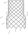
- FIG. 1 is a side-view of an embodiment of a stent 100.
- the stent 100 includes a braided wire body 102 having a proximal end 104 and a distal end 106.
- the braided wire body 102 has a hollow, tubular structure configured to be deployed inside a body lumen.
- the stent 100 is hollow so that body fluid can pass therethrough, once the stent 100 is deployed within the body lumen.
- the stent 100 abuts an inner wall of the body lumen, and thus the diameter of the stent 100 is determined based on the diameter of the body lumen in which the stent is to be deployed.
- the wires of braided stent 100 are made up of one or more biocompatible materials. Examples include biocompatible metals or metal alloys, composites, or polymers.
- the inner or outer surface of the hollow stent is coated with one or more materials.
- the stent can have a coating of carbon, platinum, or heparin, which can decrease, impede, or prevent the occurrence of thrombosis.
- the biocompatible polymers include synthetic polymeric materials and bioabsorbable or biodegradable polymeric materials.
- the wires of the stent 100 are manufactured using biocompatible metals or alloys such as, but not limited to, nitinol, stainless steel, cobalt-based alloy such as Elgiloy, platinum, gold, titanium, tantalum, niobium, polymeric materials and combinations thereof.
- Exemplary synthetic polymeric materials include, but are not limited to, polyesters, including polyethylene terephthalate (PET) polyesters, polypropylenes, polyethylenes, polyurethanes, polyolefins, polyvinyls, polymethylacetates, polyamides, naphthalane dicarboxylene derivatives, silks, and polytetrafluoroethylenes.
- the polymeric materials further include a metallic, a glass, ceramic or carbon constituent or fiber.
- bioabsorbable or biodegradable polymeric materials include poly(L-lactide) (PLLA), poly(D,L-lactide) (PLA), poly(glycolide) (PGA), poly(L-lactide-co-D,L-lactide) (PLLA/PLA), poly(L-lactide-co-glycolide) (PLLA/PGA), poly(D,L-lactide-co-glycolide) (PLA/PGA), poly(glycolide-co-trimethylene carbonate) (PGA/PTMC), polydioxanone (PDS), Polycaprolactone (PCL), polyhydroxybutyrate (PHBT), poly(phosphazene) poly(D,L-lactide-co-caprolactone) PLA/PCL), poly(glycolide-co-caprolactone) (PGA/PCL), poly(phosphate ester), and the like.
- wires of the stent 100 are made from polymeric materials that include radiopaque materials, such as metallic-based powders or ceramic-based powders, particulates or pastes that may be incorporated into the polymeric material.
- the radiopaque material may be blended with the polymer composition from which the polymeric wire is formed, and subsequently fashioned into the stent as described herein.
- the radiopaque material may be applied to the surface of the metal or polymer stent.
- various radiopaque materials and their salts and derivatives may be used including, without limitation, bismuth, barium and its salts such as barium sulfate, tantalum, tungsten, gold, platinum and titanium.
- Metallic complexes useful as radiopaque materials are also contemplated.
- the stent may be selectively made radiopaque at desired areas along the wire or made be fully radiopaque, depending on the desired end-product and application.
- wires of the stent 100 have an inner core of tantalum, gold, platinum, iridium or a combination of thereof, and an outer member or layer of nitinol to provide a composite wire for improved radiocapicity or visibility.
- the inner core may be platinum, and the outer layer may be nitinol, for example.
- the inner core of platinum represents about at least 10% of the wire based on the overall cross-sectional area.
- nitinol having shape memory properties and ninitol sans shape memory properties can be employed in formation of the wire.
- the wires may be made from nitinol, or a composite wire having a central core of platinum and an outer layer of nitinol.
- the stent 100 is formed by braiding one or more wires together.
- One such example is shown in FIG. 2 , where the stent 100 is made by braiding a first wire 202 and a second wire 204.
- the two wires 202 and 204 are braided in a helical pattern, wherein the first wire 202 and the second wire 204 alternate with one another.
- the first and second wires 202 and 204 can be braided to form a variety of patterns for example, corrugated, serpentine, coil, etc.
- the first wire 202 has a first cross-sectional area that is different from a second cross-sectional area of the second wire 204.
- the first cross-sectional area is greater than the second cross-sectional area; in some other embodiments, however, the second cross-sectional area is greater than the first cross-sectional area, as depicted in FIGs. 6 and 7 .
- Differing cross-sectional areas of the two wires 202 and 204 contributes to increased kink resistance and increased radial force of the stent 100 while yielding a stent 100 that can be sufficiently radially compressed for loading into the delivery catheter.
- At least some embodiments of the stent 100 herein disclosed have a greater expanded radial force and are also able to be readily compressed for loading into a suitably sized and constructed delivery device. This is useful, for example, where the delivery catheter is required to be inserted through the working channel of an endoscope.
- An increase in the radial force of the stent 100, when compared to stents having wires of the same diameter, is realized through comparison of the area moment of inertia, I, and the cross-sectional area, A, of such stent wires, which have a direct relation to the bending stiffness of the braided wires (e.g., 202, 204).
- I ⁇ 4 r 4 where r is the radius of the wire.
- cross-sectional area, A of a single wire
- Stent A a prior art stent, for example as shown in FIG. 8 , formed from a 0.008" (0.203 mm) diameter wire.
- Stent B stent formed from alternating 0.007" (0.178 mm) and 0.010" (0.254 mm) diameter wires.
- Stent C stent formed from alternating 0.006" (0.152 mm) and 0.011" (0.279 mm) diameter wires.
- the area moment of inertia increases to the 4th power of the wire radius while the cross-sectional area of the wire increases with the square of the wires' (202 and 204) radius.
- the volume occupied within the delivery device by stent B or stent C is greater than for stent A, for example, the bending stiffness of the wires increases dramatically for stents B and C in comparison to stent A.
- the volume occupied by the stent is a function of the cross-sectional areas of the wires.
- the two wires 202 and 204 combine for net gains of stent radial force (compared to known stent A, for example) while still maintaining similar to only slightly higher wire cross-sectional areas.
- the elastic modulus, E is a material property, it is not considered as part of the calculation because it is merely a scaling factor for a given material.
- the first wire 202 has a diameter of 0.007" and the second wire 204 has a diameter of 0.010".
- the wire sizes can be in any suitable combination, for example, 0.006" and 0.011" paired together or 0.005" (0.127 mm) and 0.012" (0.305 mm) paired together.
- Use of such wires in an alternating pattern provides a stent with a higher radial force while maintaining similar or the same overall cross-sectional area of (combined) wire, when compared to the PRIOR ART stent (e.g., FIG. 8 , Stent A, above).
- stent B has a 16.4% increase in wire cross-sectional area but a 51.4% increase in bending stiffness over stent A.
- Stent C has a 22.7% increase in wire cross-sectional area but a 95.4% increase in bending stiffness when compared to stent A.
- the stent 100 can comprise any suitable number of different sizes of diameters.
- the stent 100 has wires of three different diameters.
- the stent 100 has wires of four, five, six, or more different diameters.
- every third, fourth, fifth, etc., wire is differently sized than the remaining wires used to form the stent.
- FIG. 2 is a side-view of the proximal end 104 of the stent 100 of FIG. 1 .
- the proximal end 104 of the stent 100 includes a plurality of peaks 103.
- the peaks 103 comprise one or more first loop ends 206 and one or more first peaks 208.
- the proximal end 104 of the stent 100 may include any suitable number of loop ends and peaks such as two, four, six, eight, ten, or the like.
- the loop ends 206 are employed to removably secure the stent 100 with a delivery system for delivery of the stent 100 into the patient's body. Details of the delivery system are discussed in conjunction with FIGs. 4 and 5 , below.
- the first loop ends 206 and the first peaks 208 may be arranged in a circumferentially alternating pattern. In some embodiments, however, the first loop ends 206 and the first peaks 208 are arranged in another suitable pattern about the circumference of the proximal end 104 of the stent.
- One such example may include two loop ends 206 repeated after each first peak 208.
- the proximal end 104 of the stent 100 may have two loop ends repeated after every single peak.
- first loop ends 206 and first peaks 208 can also be disposed on the distal end 106.
- the first loop end 206 includes a first parallel portion 210a, a second parallel portion 210b, and a bent portion 212.
- the two parallel portions 210a and 210b are connected to one another via the bent portion 212. At least a portion of the two parallel portions extends beyond the first peaks 208 (as shown in FIG. 2 ).
- the parallel portions 210a, 210b extend parallel to one another along a longitudinal axis of the stent 100.
- the first loop end 206 forms a crescent-shaped hook type structure suitable for engaging a portion of the delivery device.
- FIG. 3B shows another example of a first loop end 306 to be used in conjunction with the stent 100 of FIGS. 1 and 2 .
- the first loop end 306 has a first curved portion 310a, a second curved portion 310b, and a bent portion 312.
- the first curved portion 310a intersects with the second curved portion 310b while being connected to one another via the bent portion 312.
- the first loop end 306 thus forms an oval-shaped closed hook structure suitable for engaging a portion of the delivery device.
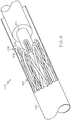
- a delivery catheter 400 includes a retractable sheath 402, an inner catheter member 404, and an anchor member 406.
- the inner catheter member 404 is slidably disposed within a lumen (not shown) of the retractable sheath 402. Further, the inner catheter member 404 is employed to receive and deploy the stent 100 into a body lumen of a patient.
- the anchor member 406 is disposed exteriorly to the inner catheter member 404, where the anchor member 406 includes a plurality of protrusions 408 extending radially therefrom.
- a proximal end of the stent 100 is coupled to the anchor member 406 such that the first loop ends (206 and 306 of FIGS. 3A and 3B ) are engaged with the protrusions 408 of the anchor member 406.
- Engagement of the stent 100 and the anchor member 406 allows a physician to advance the delivery catheter 400 inside the body lumen. Once a target location within the body lumen is reached, the physician manipulates the delivery catheter 400 by retracting the retractable sheath 402.
- the distal end 106 of the stent 100 starts to expand, for example where the stent is self-expanding.
- the proximal end 104 of the stent 100 remains engaged to the protrusions 408 so that the retractable sheath 408 can be moved distally relative to the stent 100, allowing the distal end 106 of the stent 100 to be reconstrained within the retractable sheath 402 and repositioned.
- the proximal end 104 of the stent begins to disengage from the protrusions 408 and the stent 100 can no longer be retracted and repositioned.
- the delivery catheter along with the inner catheter member 404, is removed from the body lumen.
- the stent 100 takes on a reduced unexpanded profile when compared to a stent having peaks 103 ( FIG. 2 ) that terminate at the same longitude as one another.
- peaks 103 FIG. 2
- offsetting the peaks 103 reduces the profile of the stent 100 in the unexpanded configuration.
- the stent 100 having staggered first peaks 208 and first loop ends 206 provides greater radial strength yet can be introduced via a similarly sized, or even smaller, catheter 400 than known stent/catheter combinations.
- the first wire 202 is used to form the first loop ends 206 and the second wire 204 is used to form the first peaks such that the smaller diameter wire (e.g., first wire 202) is placed over the protrusions 408.
- the smaller diameter wire e.g., first wire 202
- Such a configuration provides a stent 100 and catheter 400 combination having a further reduced delivery profile.
Claims (15)
- Stent comprenant:un corps de fils tressés ayant une extrémité proximale et une extrémité distale, le corps de fils tressés formé d'au moins un premier fil et d'au moins un second fil, le premier fil ayant une première aire en section transversale et le second fil ayant une seconde aire en section transversale différente de la première aire en section transversale; dans lequel l'extrémité proximale du corps de fils tressés comprend une pluralité de pics, les pics comprenant des premiers pics et des premières extrémités de boucle, les premières extrémités de boucle alternant circonférentiellement avec les premiers pics, les premières extrémités de boucle s'étendant de manière proximale au-delà des premiers pics,caractérisé en ce que les premières extrémités de boucle incluent chacune une première partie parallèle et une seconde partie parallèle et une partie pliée, les deux parties parallèles étant reliées l'une à l'autre via la partie pliée, et avec au moins une partie des première et seconde parties parallèles s'étendant au-delà des premiers pics.
- Stent selon la revendication 1, dans lequel l'aire en section transversale du second fil est supérieure à l'aire en section transversale du premier fil.
- Stent selon l'une quelconque des revendications précédentes, dans lequel les premier et second fils sont agencés selon un motif hélicoïdal.
- Stent selon l'une quelconque des revendications précédentes, dans lequel les premier et second fils alternent l'un avec l'autre.
- Stent selon l'une quelconque des revendications précédentes, dans lequel le second fil a un diamètre en section transversale entre 0,178 mm (0,007") et 0,305 mm (0,012").
- Stent selon l'une quelconque des revendications précédentes, dans lequel le premier fil a un diamètre en section transversale entre 0,127 mm (0,005") et 0,178 mm (0,007").
- Stent selon l'une quelconque des revendications précédentes, dans lequel le second fil a une aire en section transversale entre 0,0248 mm carré (0,000038 pouce carré) et 0,0774 mm carré (0,00012 pouce carré).
- Stent selon l'une quelconque des revendications précédentes, dans lequel le premier fil a une aire en section transversale entre 0,0122 mm carré (0,000019 pouce carré) et 0,0251 mm carré (0,00039 pouce carré).
- Stent selon l'une quelconque des revendications précédentes, dans lequel au moins l'un des premier et second fils est un fil composite.
- Stent selon la revendication 9, dans lequel le fil composite inclut du nitinol.
- Stent selon la revendication 9, dans lequel le fil composite inclut une âme radio-opaque.
- Système de mise en place de cathéter et de stent comprenant:un stent ayant une extrémité proximale et une extrémité distale, l'extrémité proximale du stent comprenant une pluralité de pics, les pics comprenant des premiers pics et des premières extrémités de boucle, les premières extrémités de boucle alternant circonférentiellement avec les premiers pics, les premières extrémités de boucle s'étendant de manière proximale au-delà des premiers pics;un cathéter de mise en place comprenant une gaine rétractable, un élément de cathéter interne et un élément d'ancrage, l'élément d'ancrage disposé extérieurement par rapport à l'élément de cathéter interne et comprenant une pluralité de saillies, les saillies s'étendant dans les premières extrémités de boucle du stent; la gaine rétractable entourant le stent et l'élément d'ancrage, caractérisé en ce que lesdites premières extrémités de boucle du stent incluent chacune une première partie parallèle et une seconde partie parallèle et une partie pliée, les deux parties parallèles étant reliées l'une à l'autre via la partie pliée et avec au moins une partie des première et seconde parties parallèles s'étendant au-delà des premiers pics.
- Cathéter de mise en place et stent selon la revendication 12, le stent comprenant en outre des premier et second fils, le premier fil ayant une première aire en section transversale et le second fil ayant une seconde aire en section transversale différente de la première aire en section transversale.
- Cathéter de mise en place et stent selon la revendication 13, dans lesquels le premier fil définit les premières extrémités de boucle et le second fil définit les premiers pics, la seconde aire en section transversale étant supérieure à la première aire en section transversale.
- Cathéter de mise en place et stent selon la revendication 12, 13 ou 14, dans lesquels le stent définit un axe longitudinal et les parties parallèles des premières extrémités de boucle du stent s'étendent parallèlement à l'axe longitudinal.
Applications Claiming Priority (2)
| Application Number | Priority Date | Filing Date | Title |
|---|---|---|---|
| US201461976754P | 2014-04-08 | 2014-04-08 | |
| PCT/US2015/024677 WO2015157258A2 (fr) | 2014-04-08 | 2015-04-07 | Dispositifs médicaux et leurs procédés d'utilisation afférents |
Publications (2)
| Publication Number | Publication Date |
|---|---|
| EP3128959A2 EP3128959A2 (fr) | 2017-02-15 |
| EP3128959B1 true EP3128959B1 (fr) | 2020-09-30 |
Family
ID=52988488
Family Applications (1)
| Application Number | Title | Priority Date | Filing Date |
|---|---|---|---|
| EP15717382.4A Active EP3128959B1 (fr) | 2014-04-08 | 2015-04-07 | Dispositifs médicaux |
Country Status (6)
| Country | Link |
|---|---|
| US (1) | US20150282960A1 (fr) |
| EP (1) | EP3128959B1 (fr) |
| JP (1) | JP6356261B2 (fr) |
| KR (1) | KR101922321B1 (fr) |
| CN (1) | CN106572913B (fr) |
| WO (1) | WO2015157258A2 (fr) |
Families Citing this family (9)
| Publication number | Priority date | Publication date | Assignee | Title |
|---|---|---|---|---|
| US9498266B2 (en) * | 2014-02-12 | 2016-11-22 | Wright Medical Technology, Inc. | Intramedullary implant, system, and method for inserting an implant into a bone |
| EP3244829B1 (fr) | 2015-01-16 | 2020-12-30 | Boston Scientific Scimed, Inc. | Dispositif médical implantable avec capacités de migration réduites |
| US10426592B2 (en) | 2016-04-11 | 2019-10-01 | Boston Scientific Scimed, Inc. | Implantable medical device with reduced migration capabilities |
| WO2018232134A1 (fr) | 2017-06-16 | 2018-12-20 | Boston Scientific Scimed, Inc. | Déploiement de stent et de manchon |
| EP3446661B1 (fr) | 2017-08-21 | 2021-12-29 | Cook Medical Technologies LLC | Géométrie et partie évasée de couronne de stent tressé |
| KR102570357B1 (ko) * | 2017-11-06 | 2023-08-23 | 이에이 파마 가부시키가이샤 | 스텐트 및 그것을 포함하는 의료기기 |
| US20200155732A1 (en) * | 2018-11-16 | 2020-05-21 | Microvention, Inc. | Radiopaque Vascular Prosthesis |
| CN112386364A (zh) * | 2020-11-10 | 2021-02-23 | 苏州中天医疗器械科技有限公司 | 混合编织支架 |
| US20230338175A1 (en) * | 2022-04-26 | 2023-10-26 | Accumedical Beijing Ltd. | Repositionable intracranial stent with retrieval mechanism |
Citations (1)
| Publication number | Priority date | Publication date | Assignee | Title |
|---|---|---|---|---|
| WO2013011502A2 (fr) * | 2011-07-21 | 2013-01-24 | 4Tech Inc. | Procédé et appareil pour la réparation d'une valvule tricuspide en utilisant une tension |
Family Cites Families (17)
| Publication number | Priority date | Publication date | Assignee | Title |
|---|---|---|---|---|
| CN1081074C (zh) * | 1998-07-09 | 2002-03-20 | 冶金工业部钢铁研究总院 | 复合式医用血管内支架 |
| US7018401B1 (en) * | 1999-02-01 | 2006-03-28 | Board Of Regents, The University Of Texas System | Woven intravascular devices and methods for making the same and apparatus for delivery of the same |
| DK1156757T3 (da) * | 1999-02-01 | 2006-04-18 | Univ Texas | Vævede intravaskulære indretninger og fremgangsmåder til fremstilling deraf |
| US7473271B2 (en) * | 2003-04-11 | 2009-01-06 | Boston Scientific Scimed, Inc. | Stent delivery system with securement and deployment accuracy |
| ES2364555T3 (es) * | 2003-05-23 | 2011-09-06 | Boston Scientific Limited | Cánulas con terminaciones en bucle incorporadas. |
| US8337543B2 (en) * | 2004-11-05 | 2012-12-25 | Boston Scientific Scimed, Inc. | Prosthesis anchoring and deploying device |
| WO2006053270A2 (fr) * | 2004-11-10 | 2006-05-18 | Boston Scientific Limited | Endoprothese vasculaire atraumatique a force de deploiement reduite, procede de fabrication de cette derniere et procede et appareil de deploiement et de positionnement de l'endoprothese vasculaire |
| WO2006081448A1 (fr) * | 2005-01-28 | 2006-08-03 | Boston Scientific Limited | Element de reperage de tuteur intravasculaire, dispositifs et procedes de reperage ou de repositionnement de tuteur intravasculaire |
| CN200939184Y (zh) * | 2006-08-22 | 2007-08-29 | 茅爱武 | 由异型丝材编织的医用支架 |
| US8052732B2 (en) * | 2006-11-14 | 2011-11-08 | Medtronic Vascular, Inc. | Delivery system for stent-graft with anchoring pins |
| US8409270B2 (en) * | 2007-04-16 | 2013-04-02 | Boston Scientific Scimed, Inc. | Radiopaque compositions, stents and methods of preparation |
| US20080262590A1 (en) * | 2007-04-19 | 2008-10-23 | Medtronic Vascular, Inc. | Delivery System for Stent-Graft |
| DE102011011180B4 (de) * | 2011-02-14 | 2015-10-01 | Acandis Gmbh & Co. Kg | Medizinische Vorrichtung mit einem expandierbaren Gittergeflecht |
| JP5751619B2 (ja) * | 2011-04-14 | 2015-07-22 | 朝日インテック株式会社 | ステント |
| CN103874794B (zh) * | 2011-09-01 | 2016-04-13 | 库克医学技术有限责任公司 | 编织的螺旋线支架及其形成方法 |
| US9320623B2 (en) * | 2011-10-04 | 2016-04-26 | Cook Medical Technologies Llc | Reduced wire profile stent |
| KR101871144B1 (ko) * | 2012-03-16 | 2018-06-27 | 마이크로벤션, 인코포레이티드 | 스텐트 및 스텐트 전달 장치 |
-
2015
- 2015-04-07 JP JP2016561789A patent/JP6356261B2/ja not_active Expired - Fee Related
- 2015-04-07 WO PCT/US2015/024677 patent/WO2015157258A2/fr active Application Filing
- 2015-04-07 KR KR1020167031141A patent/KR101922321B1/ko active IP Right Grant
- 2015-04-07 EP EP15717382.4A patent/EP3128959B1/fr active Active
- 2015-04-07 CN CN201580030739.XA patent/CN106572913B/zh active Active
- 2015-04-07 US US14/680,564 patent/US20150282960A1/en not_active Abandoned
Patent Citations (1)
| Publication number | Priority date | Publication date | Assignee | Title |
|---|---|---|---|---|
| WO2013011502A2 (fr) * | 2011-07-21 | 2013-01-24 | 4Tech Inc. | Procédé et appareil pour la réparation d'une valvule tricuspide en utilisant une tension |
Also Published As
| Publication number | Publication date |
|---|---|
| KR20160143767A (ko) | 2016-12-14 |
| EP3128959A2 (fr) | 2017-02-15 |
| JP6356261B2 (ja) | 2018-07-11 |
| WO2015157258A3 (fr) | 2016-02-18 |
| CN106572913B (zh) | 2019-02-12 |
| CN106572913A (zh) | 2017-04-19 |
| KR101922321B1 (ko) | 2018-11-26 |
| US20150282960A1 (en) | 2015-10-08 |
| JP2017513580A (ja) | 2017-06-01 |
| WO2015157258A2 (fr) | 2015-10-15 |
Similar Documents
| Publication | Publication Date | Title |
|---|---|---|
| EP3128959B1 (fr) | Dispositifs médicaux | |
| US11523919B2 (en) | Stent | |
| EP3597256B1 (fr) | Stent intégré présentant une boucle de repositionnement et d'extraction | |
| EP3043753B1 (fr) | Échafaudages tressés | |
| CA2919528C (fr) | Valve anti-reflux en silicone pour stents polymeres | |
| US20080009934A1 (en) | Endoprosthesis delivery system with stent holder | |
| US20050021128A1 (en) | Compliant, porous, rolled stent | |
| WO2012159454A1 (fr) | Motif d'endoprothèse à élution de médicament, biodégradable | |
| KR20170118154A (ko) | 인입 가능한 앵커를 가진 스텐트 | |
| EP2327380B1 (fr) | Stent doté d'éléments de fonction | |
| US20220218461A1 (en) | Stent with atraumatic spacer | |
| US20210378849A1 (en) | Stent with Enhanced Low Crimping Profile | |
| WO2023021310A1 (fr) | Stent à profil de sertissage bas amélioré |
Legal Events
| Date | Code | Title | Description |
|---|---|---|---|
| STAA | Information on the status of an ep patent application or granted ep patent |
Free format text: STATUS: THE INTERNATIONAL PUBLICATION HAS BEEN MADE |
|
| PUAI | Public reference made under article 153(3) epc to a published international application that has entered the european phase |
Free format text: ORIGINAL CODE: 0009012 |
|
| STAA | Information on the status of an ep patent application or granted ep patent |
Free format text: STATUS: REQUEST FOR EXAMINATION WAS MADE |
|
| 17P | Request for examination filed |
Effective date: 20161108 |
|
| AK | Designated contracting states |
Kind code of ref document: A2 Designated state(s): AL AT BE BG CH CY CZ DE DK EE ES FI FR GB GR HR HU IE IS IT LI LT LU LV MC MK MT NL NO PL PT RO RS SE SI SK SM TR |
|
| AX | Request for extension of the european patent |
Extension state: BA ME |
|
| DAV | Request for validation of the european patent (deleted) | ||
| DAX | Request for extension of the european patent (deleted) | ||
| GRAP | Despatch of communication of intention to grant a patent |
Free format text: ORIGINAL CODE: EPIDOSNIGR1 |
|
| STAA | Information on the status of an ep patent application or granted ep patent |
Free format text: STATUS: GRANT OF PATENT IS INTENDED |
|
| INTG | Intention to grant announced |
Effective date: 20200420 |
|
| GRAS | Grant fee paid |
Free format text: ORIGINAL CODE: EPIDOSNIGR3 |
|
| GRAA | (expected) grant |
Free format text: ORIGINAL CODE: 0009210 |
|
| STAA | Information on the status of an ep patent application or granted ep patent |
Free format text: STATUS: THE PATENT HAS BEEN GRANTED |
|
| AK | Designated contracting states |
Kind code of ref document: B1 Designated state(s): AL AT BE BG CH CY CZ DE DK EE ES FI FR GB GR HR HU IE IS IT LI LT LU LV MC MK MT NL NO PL PT RO RS SE SI SK SM TR |
|
| REG | Reference to a national code |
Ref country code: CH Ref legal event code: EP Ref country code: GB Ref legal event code: FG4D |
|
| REG | Reference to a national code |
Ref country code: DE Ref legal event code: R096 Ref document number: 602015059783 Country of ref document: DE Ref country code: AT Ref legal event code: REF Ref document number: 1317996 Country of ref document: AT Kind code of ref document: T Effective date: 20201015 |
|
| REG | Reference to a national code |
Ref country code: IE Ref legal event code: FG4D |
|
| REG | Reference to a national code |
Ref country code: NL Ref legal event code: FP |
|
| PG25 | Lapsed in a contracting state [announced via postgrant information from national office to epo] |
Ref country code: GR Free format text: LAPSE BECAUSE OF FAILURE TO SUBMIT A TRANSLATION OF THE DESCRIPTION OR TO PAY THE FEE WITHIN THE PRESCRIBED TIME-LIMIT Effective date: 20201231 Ref country code: SE Free format text: LAPSE BECAUSE OF FAILURE TO SUBMIT A TRANSLATION OF THE DESCRIPTION OR TO PAY THE FEE WITHIN THE PRESCRIBED TIME-LIMIT Effective date: 20200930 Ref country code: HR Free format text: LAPSE BECAUSE OF FAILURE TO SUBMIT A TRANSLATION OF THE DESCRIPTION OR TO PAY THE FEE WITHIN THE PRESCRIBED TIME-LIMIT Effective date: 20200930 Ref country code: FI Free format text: LAPSE BECAUSE OF FAILURE TO SUBMIT A TRANSLATION OF THE DESCRIPTION OR TO PAY THE FEE WITHIN THE PRESCRIBED TIME-LIMIT Effective date: 20200930 Ref country code: BG Free format text: LAPSE BECAUSE OF FAILURE TO SUBMIT A TRANSLATION OF THE DESCRIPTION OR TO PAY THE FEE WITHIN THE PRESCRIBED TIME-LIMIT Effective date: 20201230 Ref country code: NO Free format text: LAPSE BECAUSE OF FAILURE TO SUBMIT A TRANSLATION OF THE DESCRIPTION OR TO PAY THE FEE WITHIN THE PRESCRIBED TIME-LIMIT Effective date: 20201230 |
|
| REG | Reference to a national code |
Ref country code: AT Ref legal event code: MK05 Ref document number: 1317996 Country of ref document: AT Kind code of ref document: T Effective date: 20200930 |
|
| PG25 | Lapsed in a contracting state [announced via postgrant information from national office to epo] |
Ref country code: RS Free format text: LAPSE BECAUSE OF FAILURE TO SUBMIT A TRANSLATION OF THE DESCRIPTION OR TO PAY THE FEE WITHIN THE PRESCRIBED TIME-LIMIT Effective date: 20200930 Ref country code: LV Free format text: LAPSE BECAUSE OF FAILURE TO SUBMIT A TRANSLATION OF THE DESCRIPTION OR TO PAY THE FEE WITHIN THE PRESCRIBED TIME-LIMIT Effective date: 20200930 |
|
| REG | Reference to a national code |
Ref country code: LT Ref legal event code: MG4D |
|
| PG25 | Lapsed in a contracting state [announced via postgrant information from national office to epo] |
Ref country code: LT Free format text: LAPSE BECAUSE OF FAILURE TO SUBMIT A TRANSLATION OF THE DESCRIPTION OR TO PAY THE FEE WITHIN THE PRESCRIBED TIME-LIMIT Effective date: 20200930 Ref country code: PT Free format text: LAPSE BECAUSE OF FAILURE TO SUBMIT A TRANSLATION OF THE DESCRIPTION OR TO PAY THE FEE WITHIN THE PRESCRIBED TIME-LIMIT Effective date: 20210201 Ref country code: EE Free format text: LAPSE BECAUSE OF FAILURE TO SUBMIT A TRANSLATION OF THE DESCRIPTION OR TO PAY THE FEE WITHIN THE PRESCRIBED TIME-LIMIT Effective date: 20200930 Ref country code: SM Free format text: LAPSE BECAUSE OF FAILURE TO SUBMIT A TRANSLATION OF THE DESCRIPTION OR TO PAY THE FEE WITHIN THE PRESCRIBED TIME-LIMIT Effective date: 20200930 Ref country code: RO Free format text: LAPSE BECAUSE OF FAILURE TO SUBMIT A TRANSLATION OF THE DESCRIPTION OR TO PAY THE FEE WITHIN THE PRESCRIBED TIME-LIMIT Effective date: 20200930 Ref country code: CZ Free format text: LAPSE BECAUSE OF FAILURE TO SUBMIT A TRANSLATION OF THE DESCRIPTION OR TO PAY THE FEE WITHIN THE PRESCRIBED TIME-LIMIT Effective date: 20200930 |
|
| PG25 | Lapsed in a contracting state [announced via postgrant information from national office to epo] |
Ref country code: PL Free format text: LAPSE BECAUSE OF FAILURE TO SUBMIT A TRANSLATION OF THE DESCRIPTION OR TO PAY THE FEE WITHIN THE PRESCRIBED TIME-LIMIT Effective date: 20200930 Ref country code: IS Free format text: LAPSE BECAUSE OF FAILURE TO SUBMIT A TRANSLATION OF THE DESCRIPTION OR TO PAY THE FEE WITHIN THE PRESCRIBED TIME-LIMIT Effective date: 20210130 Ref country code: AL Free format text: LAPSE BECAUSE OF FAILURE TO SUBMIT A TRANSLATION OF THE DESCRIPTION OR TO PAY THE FEE WITHIN THE PRESCRIBED TIME-LIMIT Effective date: 20200930 Ref country code: AT Free format text: LAPSE BECAUSE OF FAILURE TO SUBMIT A TRANSLATION OF THE DESCRIPTION OR TO PAY THE FEE WITHIN THE PRESCRIBED TIME-LIMIT Effective date: 20200930 Ref country code: ES Free format text: LAPSE BECAUSE OF FAILURE TO SUBMIT A TRANSLATION OF THE DESCRIPTION OR TO PAY THE FEE WITHIN THE PRESCRIBED TIME-LIMIT Effective date: 20200930 |
|
| PG25 | Lapsed in a contracting state [announced via postgrant information from national office to epo] |
Ref country code: SK Free format text: LAPSE BECAUSE OF FAILURE TO SUBMIT A TRANSLATION OF THE DESCRIPTION OR TO PAY THE FEE WITHIN THE PRESCRIBED TIME-LIMIT Effective date: 20200930 |
|
| REG | Reference to a national code |
Ref country code: DE Ref legal event code: R097 Ref document number: 602015059783 Country of ref document: DE |
|
| PLBE | No opposition filed within time limit |
Free format text: ORIGINAL CODE: 0009261 |
|
| STAA | Information on the status of an ep patent application or granted ep patent |
Free format text: STATUS: NO OPPOSITION FILED WITHIN TIME LIMIT |
|
| PG25 | Lapsed in a contracting state [announced via postgrant information from national office to epo] |
Ref country code: DK Free format text: LAPSE BECAUSE OF FAILURE TO SUBMIT A TRANSLATION OF THE DESCRIPTION OR TO PAY THE FEE WITHIN THE PRESCRIBED TIME-LIMIT Effective date: 20200930 |
|
| 26N | No opposition filed |
Effective date: 20210701 |
|
| PG25 | Lapsed in a contracting state [announced via postgrant information from national office to epo] |
Ref country code: IT Free format text: LAPSE BECAUSE OF FAILURE TO SUBMIT A TRANSLATION OF THE DESCRIPTION OR TO PAY THE FEE WITHIN THE PRESCRIBED TIME-LIMIT Effective date: 20200930 |
|
| PG25 | Lapsed in a contracting state [announced via postgrant information from national office to epo] |
Ref country code: MC Free format text: LAPSE BECAUSE OF FAILURE TO SUBMIT A TRANSLATION OF THE DESCRIPTION OR TO PAY THE FEE WITHIN THE PRESCRIBED TIME-LIMIT Effective date: 20200930 Ref country code: SI Free format text: LAPSE BECAUSE OF FAILURE TO SUBMIT A TRANSLATION OF THE DESCRIPTION OR TO PAY THE FEE WITHIN THE PRESCRIBED TIME-LIMIT Effective date: 20200930 |
|
| PG25 | Lapsed in a contracting state [announced via postgrant information from national office to epo] |
Ref country code: LU Free format text: LAPSE BECAUSE OF NON-PAYMENT OF DUE FEES Effective date: 20210407 |
|
| REG | Reference to a national code |
Ref country code: BE Ref legal event code: MM Effective date: 20210430 |
|
| PG25 | Lapsed in a contracting state [announced via postgrant information from national office to epo] |
Ref country code: LI Free format text: LAPSE BECAUSE OF NON-PAYMENT OF DUE FEES Effective date: 20210430 Ref country code: CH Free format text: LAPSE BECAUSE OF NON-PAYMENT OF DUE FEES Effective date: 20210430 Ref country code: FR Free format text: LAPSE BECAUSE OF NON-PAYMENT OF DUE FEES Effective date: 20210430 |
|
| PG25 | Lapsed in a contracting state [announced via postgrant information from national office to epo] |
Ref country code: IS Free format text: LAPSE BECAUSE OF FAILURE TO SUBMIT A TRANSLATION OF THE DESCRIPTION OR TO PAY THE FEE WITHIN THE PRESCRIBED TIME-LIMIT Effective date: 20210130 |
|
| PG25 | Lapsed in a contracting state [announced via postgrant information from national office to epo] |
Ref country code: BE Free format text: LAPSE BECAUSE OF NON-PAYMENT OF DUE FEES Effective date: 20210430 |
|
| PGFP | Annual fee paid to national office [announced via postgrant information from national office to epo] |
Ref country code: IE Payment date: 20230322 Year of fee payment: 9 |
|
| PG25 | Lapsed in a contracting state [announced via postgrant information from national office to epo] |
Ref country code: HU Free format text: LAPSE BECAUSE OF FAILURE TO SUBMIT A TRANSLATION OF THE DESCRIPTION OR TO PAY THE FEE WITHIN THE PRESCRIBED TIME-LIMIT; INVALID AB INITIO Effective date: 20150407 |
|
| PGFP | Annual fee paid to national office [announced via postgrant information from national office to epo] |
Ref country code: GB Payment date: 20230321 Year of fee payment: 9 |
|
| PG25 | Lapsed in a contracting state [announced via postgrant information from national office to epo] |
Ref country code: CY Free format text: LAPSE BECAUSE OF FAILURE TO SUBMIT A TRANSLATION OF THE DESCRIPTION OR TO PAY THE FEE WITHIN THE PRESCRIBED TIME-LIMIT Effective date: 20200930 |
|
| PGFP | Annual fee paid to national office [announced via postgrant information from national office to epo] |
Ref country code: NL Payment date: 20230321 Year of fee payment: 9 |
|
| P01 | Opt-out of the competence of the unified patent court (upc) registered |
Effective date: 20230530 |
|
| PGFP | Annual fee paid to national office [announced via postgrant information from national office to epo] |
Ref country code: DE Payment date: 20230321 Year of fee payment: 9 |
|
| PGFP | Annual fee paid to national office [announced via postgrant information from national office to epo] |
Ref country code: IE Payment date: 20240322 Year of fee payment: 10 |