EP3128802B1 - Trägersteuerungsverfahren und system - Google Patents
Trägersteuerungsverfahren und system Download PDFInfo
- Publication number
- EP3128802B1 EP3128802B1 EP14890344.6A EP14890344A EP3128802B1 EP 3128802 B1 EP3128802 B1 EP 3128802B1 EP 14890344 A EP14890344 A EP 14890344A EP 3128802 B1 EP3128802 B1 EP 3128802B1
- Authority
- EP
- European Patent Office
- Prior art keywords
- access node
- access network
- network access
- air interface
- mme
- Prior art date
- Legal status (The legal status is an assumption and is not a legal conclusion. Google has not performed a legal analysis and makes no representation as to the accuracy of the status listed.)
- Active
Links
Images


Classifications
-
- H—ELECTRICITY
- H04—ELECTRIC COMMUNICATION TECHNIQUE
- H04W—WIRELESS COMMUNICATION NETWORKS
- H04W76/00—Connection management
- H04W76/10—Connection setup
-
- H—ELECTRICITY
- H04—ELECTRIC COMMUNICATION TECHNIQUE
- H04W—WIRELESS COMMUNICATION NETWORKS
- H04W76/00—Connection management
- H04W76/30—Connection release
- H04W76/34—Selective release of ongoing connections
-
- H—ELECTRICITY
- H04—ELECTRIC COMMUNICATION TECHNIQUE
- H04M—TELEPHONIC COMMUNICATION
- H04M15/00—Arrangements for metering, time-control or time indication ; Metering, charging or billing arrangements for voice wireline or wireless communications, e.g. VoIP
- H04M15/66—Policy and charging system
-
- H—ELECTRICITY
- H04—ELECTRIC COMMUNICATION TECHNIQUE
- H04W—WIRELESS COMMUNICATION NETWORKS
- H04W72/00—Local resource management
- H04W72/50—Allocation or scheduling criteria for wireless resources
- H04W72/54—Allocation or scheduling criteria for wireless resources based on quality criteria
- H04W72/543—Allocation or scheduling criteria for wireless resources based on quality criteria based on requested quality, e.g. QoS
-
- H—ELECTRICITY
- H04—ELECTRIC COMMUNICATION TECHNIQUE
- H04W—WIRELESS COMMUNICATION NETWORKS
- H04W76/00—Connection management
- H04W76/10—Connection setup
- H04W76/12—Setup of transport tunnels
-
- H—ELECTRICITY
- H04—ELECTRIC COMMUNICATION TECHNIQUE
- H04W—WIRELESS COMMUNICATION NETWORKS
- H04W76/00—Connection management
- H04W76/20—Manipulation of established connections
- H04W76/27—Transitions between radio resource control [RRC] states
-
- H—ELECTRICITY
- H04—ELECTRIC COMMUNICATION TECHNIQUE
- H04W—WIRELESS COMMUNICATION NETWORKS
- H04W28/00—Network traffic management; Network resource management
- H04W28/16—Central resource management; Negotiation of resources or communication parameters, e.g. negotiating bandwidth or QoS [Quality of Service]
- H04W28/24—Negotiating SLA [Service Level Agreement]; Negotiating QoS [Quality of Service]
-
- H—ELECTRICITY
- H04—ELECTRIC COMMUNICATION TECHNIQUE
- H04W—WIRELESS COMMUNICATION NETWORKS
- H04W76/00—Connection management
- H04W76/10—Connection setup
- H04W76/11—Allocation or use of connection identifiers
-
- H—ELECTRICITY
- H04—ELECTRIC COMMUNICATION TECHNIQUE
- H04W—WIRELESS COMMUNICATION NETWORKS
- H04W76/00—Connection management
- H04W76/20—Manipulation of established connections
- H04W76/22—Manipulation of transport tunnels
-
- Y—GENERAL TAGGING OF NEW TECHNOLOGICAL DEVELOPMENTS; GENERAL TAGGING OF CROSS-SECTIONAL TECHNOLOGIES SPANNING OVER SEVERAL SECTIONS OF THE IPC; TECHNICAL SUBJECTS COVERED BY FORMER USPC CROSS-REFERENCE ART COLLECTIONS [XRACs] AND DIGESTS
- Y02—TECHNOLOGIES OR APPLICATIONS FOR MITIGATION OR ADAPTATION AGAINST CLIMATE CHANGE
- Y02D—CLIMATE CHANGE MITIGATION TECHNOLOGIES IN INFORMATION AND COMMUNICATION TECHNOLOGIES [ICT], I.E. INFORMATION AND COMMUNICATION TECHNOLOGIES AIMING AT THE REDUCTION OF THEIR OWN ENERGY USE
- Y02D30/00—Reducing energy consumption in communication networks
- Y02D30/70—Reducing energy consumption in communication networks in wireless communication networks
Definitions
- the present invention relates to the field of communications technologies, and in particular, to bearer control methods and a bearer control system.
- a terminal device such as user equipment (User Equipment, UE for short)
- a packet data gateway Public Data Network Gateway, PGW for short
- PGW Packet Data Network Gateway
- LTE Long Term Evolution
- a bearer from the UE to the PGW determines a data transmission connection between the UE and the PGW, and the bearer from the UE to the PGW is formed by connecting multiple sections of bearers mapped onto different network nodes.
- Each section of bearer is identified by quality of service (Quality of Service, QoS for short).
- Service data flows may be filtered to different bearers by using a data flow filter, so that service data flows having a same QoS requirement may be aggregated on a same bearer for transmission.
- a process in which a network establishes, modifies, or deletes an end-to-end bearer according to the terminal device and the QoS of the service data flow is a part of session management.
- mobility management on the terminal device is also an important part in the cellular network, and the mobility management mainly includes updating of a location area in which the terminal device is located and paging of the terminal device.
- a core network gateway establishes an end-to-end bearer according to the QoS requirement, and maps the service data flow of the terminal device onto the bearer.
- the core network gateway does not know a resource status of an access network.
- the end-to-end bearer needs to be modified.
- the end-to-end bearer is bound to an access technology, and cannot support a mode in which service data flows are transmitted by using multiple access technologies and resources of the access technologies are dynamically used according to a resource status.
- the core network gateway needs to send a downlink data notification to the mobility management entity, so as to trigger paging, and the mobility management entity pages an access network device in a location area registered by the terminal device.
- a problem that needs to be resolved in the present invention is how to implement flexible control on a bearer and implement transmission of a service data flow of a terminal device by using multiple access technologies.
- a function of an MME is simplified by performing hierarchical management on a bearer between UE and a network; an access network access node controls transmission of a service data flow on the air interface bearer according to QoS information. This enhances management on an air interface resource status by the access network access node, further, improves network resource management efficiency and a network capacity, reduces power consumption, and provides a basis for further evolution of a mobile network.
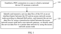
- FIG. 1 is a flowchart of a bearer control method according to Embodiment 1 of the present invention.
- the bearer control method may mainly include: Step 100: Establish a packet data network PDN connection when a terminal device UE accesses a network.
- network access registration first needs to be performed, and authentication is performed on the UE by obtaining subscription information between the UE and the network.
- the subscription information may be saved in a home subscriber server (Home Subscriber Server, HSS for short).
- the foregoing network access registration process of the UE is an attach procedure. After the attach procedure, the UE already accesses the network.
- a PDN policy session further needs to be added, so as to establish a PDN connection between the UE and the network.
- the HSS is a database saving user subscription information, and the subscription information may include: a user category, a service use right, a quality-of-service class, a charging mode, and the like that are negotiated by the user with an operator.
- Step 120 Identify and transmit a service data flow of the UE on an air interface bearer between the UE and an access network access node according to obtained quality of service QoS information, and transmit the service data flow by using a transmission tunnel between the access network access node and a core network gateway, or directly send the service data flow to a packet data network by using the access network access node.
- the UE receives the QoS information from a policy and charging rule function (Policy and Charging Rule Function, PCRF) decision point by using the PDN connection.
- the service data flow of the UE is identified according to a requirement of the QoS information.
- a data path of a granularity of the foregoing PDN connection includes an air interface bearer part and a transmission tunnel part.
- the air interface bearer is a transmission path between the UE and the access network access node (for example, an eNodeB).
- the service data flow of the UE is identified according to the requirement of the received QoS information, and service data flows that do not meet the requirement of the QoS information are separately matched with different air interface bearers.
- the access network access node separately allocates an air interface resource to different air interface bearers, so as to transmit the service data flow of the UE.
- the transmission tunnel part is the transmission tunnel between the access network access node and the PCRF, is used to transmit the service data flow between the access network access node and the PCRF, and does not require that the service data flow is identified according to the requirement of the QoS information.
- the access network access node may directly send, to the packet data network, the service data flow that is received from the UE by using the air interface bearer.
- the data path of the granularity of the PDN connection established between the access network access node and the core network gateway bears all uplink data and downlink data of the PDN connection of the UE.
- context information of the UE saved in each network node may be deleted and released on the data path, so as to improve network resource utilization.
- the data path may be reserved.
- the data path of the granularity of the PDN connection that is of the UE and that is between the access network access node in which the UE initiates the service request and the core network gateway may be recovered.
- the access network access node may be an evolved NodeB (Evolved NodeB, eNB) in the LTE, a base station (NodeB) and a radio network controller (Radio Network Controller, RNC) in the Universal Mobile Telecommunications System (Universal Mobile Telecommunications System, UMTS), a base transceiver station (Base Transceiver Station, BTS) and a base station controller (Base Station Controller, BSC) in the Global System for Mobile Communications (Global System for Mobile Communications, GSM), and a single radio network controller (Single Radio Controller, SRC), where the SRC is an access network that integrates a multi-mode radio network controller or coordinator, and the access network may include the LTE, the UMTS, and a network of access technologies such as the Code Division Multiple Access (Code Division Multiple Access, CDMA) 2000 and the GSM, where the LTE belongs to the 4th Generation Mobile Communication (the 4th Generation Mobile Communication, 4G) technology, the UMTS and
- RNC Radio Network Controller
- UMTS Universal Mobile
- the core network gateway may be a gateway GPRS support node (Gateway GPRS Support Node, GGSN) of a general packet radio service (General Packet Radio Service, GPRS) core network, and a serving gateway (Serving Gateway, SGW) and a PGW of a 4G core network (Evolved Packet Core, EPC).
- a mobility management entity may be a mobility management entity (Mobility Management Entity, MME) of the LTE, a serving GPRS support node (Serving GPRS Support Node, SGSN) of the UMTS and the GSM, and a core network controller (Core network Controller, CC) unrelated to the access technology.
- MME mobility management entity
- SGSN Serving GPRS support node
- SGSN Serving GPRS support Node
- CC core network Controller
- a function of an MME is simplified by performing hierarchical management on a bearer between UE and a network; an access network access node controls transmission of a service data flow on the air interface bearer according to QoS information.
- This enhances management on an air interface resource status by the access network access node, further, improves network resource management efficiency and a network capacity, reduces power consumption, and provides a basis for further evolution of a mobile network.
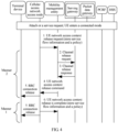
- FIG. 2 is a flowchart of a bearer control method according to Embodiment 2 of the present invention. Steps that have a same reference sign in FIG. 2 and FIG. 1 have a same function. For brevity, detailed descriptions about these steps are omitted.
- step 100 may specifically include: Step 200: Establish a PDN connection policy session between an access network access node and a policy and charging rule function PCRF decision point.
- step 200 may be implemented in either of the following two possible manners:
- each node in a network may save identification information of the UE.
- each node in the network may further save identification information of a PDN.
- the access network access node or the MME may find a corresponding PCRF in the network by using the saved identification information of the UE and the saved identification information of the PDN, and initiate establishing of the PDN connection policy session.
- Manner 1 may be used, and the PDN connection policy session is added to the access network control session between the access network access node and the PCRF. If all PDN connections of the UE are respectively served by multiple PCRFs, Manner 2 may be used, the PDN connection policy session is added between the access network access node and the MME, and the MME and the PCRF establish the PDN connection policy session between the MME and the PCRF.
- the bearer control method further includes:
- the access network access node receives the QoS information from the PCRF by using the MME, so that the access network access node may subsequently identify a service data flow of the UE according to the QoS information, and complete the radio resource control (Radio Resource Control, RRC) connection reconfiguration.
- RRC Radio Resource Control
- the access network access node after receiving the QoS information, identifies the service data flow of the UE according to a requirement of the QoS information, establishes a mapping relationship between different service data flows that meet different requirements of the QoS information and different air interface bearers, and allocates, to different air interface bearers, the air interface resource, that is, the air interface resource used when different service data flows are transmitted on different air interface bearers.
- Step 220 further includes:
- the RRC connection reconfiguration message includes the mapping relationship between the service data flow of the UE and the air interface bearer and an identifier of the air interface resource, and the identifier of the air interface resource is used to indicate the air interface resource used by the UE to transmit, on the air interface bearer, the service data flow.
- the access network access node receives the RRC connection reconfiguration success response from the UE, so that the RRC connection reconfiguration process is completed.
- the access network access node may further obtain the QoS information (such as bandwidth, a priority, a delay, and a packet loss rate) of the service data flow by using uplink and downlink data flows that are of the UE and that are identified by the access network access node. Further, if the UE transmits the service data flow by using the foregoing data path, a node in a network (for example, the MME) may save a context of the UE, including the mapping relationship that is between the service data flow and the QoS information and that is in the context.
- the QoS information such as bandwidth, a priority, a delay, and a packet loss rate
- the access network access node may obtain, from the MME, the mapping relationship that is between the service data flow and the QoS information and that is in the context, allocate uplink and downlink resources (especially air interface radio resources) to the UE, map the uplink and downlink resources to the air interface bearer, and send, by using the RRC connection reconfiguration message to the UE, the mapping relationship between the service data flow and the air interface bearer and the air interface resource that is used when the UE transmits, on the air interface bearer, the service data flow.
- uplink and downlink resources especially air interface radio resources
- a core network gateway may include a serving gateway SGW and/or a packet data gateway PGW.
- the bearer control method may further include: Step 230: The MME receives a PDN connection establishment request sent by the UE, where the PDN connection establishment request carries a PDN identifier access point name APN.
- the UE may send, by using the air interface connection, the PDN connection establishment request to the MME, where the PDN connection establishment request may carry the PDN identifier access point name (Access Point Name, APN for short), and the APN may be used to indicate a PDN network used by the UE.
- the PDN connection establishment request may also be an attach request, and the MME may perform authentication on the UE according to subscription information that is of the UE and that is saved in the HSS, so as to ensure security of a network.
- subscription information refer to the related description of the bearer control method in Embodiment 1 of the present invention.
- Step 240 The MME selects the core network gateway according to the APN and subscription information of the UE.
- Step 250 The MME sends a session establishment request to the core network gateway, where the session establishment request carries first channel information allocated by the serving gateway to the PDN connection, the first channel information includes an IP address and a port number that are of a first channel and that are allocated by the access network access node to the UE, and the first channel information is used to establish the first channel between the serving gateway and the packet data gateway.
- Step 260 The core network gateway returns a session establishment response to the MME, where the session establishment response carries second channel information allocated by the packet data gateway to the PDN connection, the second channel information includes an IP address and a port number that are of a second channel and that are allocated by the core network gateway to the UE, and the second channel information is used to establish the second channel between the packet data gateway and the serving gateway; where the first channel and the second channel form the transmission tunnel, which is used to transmit the service data flow between the access network access node and the core network gateway.
- the MME may select the core network gateway for the UE according to the received APN and the subscription information of the UE, where the core network gateway may include the packet data gateway and the serving gateway; and send the session establishment request to the serving gateway, and then send the session establishment request to the packet data gateway by using the serving gateway, where: the session establishment request may carry the first channel information allocated by the serving gateway to the PDN connection that needs to be established; and the first channel information may include the IP address, the port number, and the like that are of the first channel and that are allocated by the access network access node to the UE, so as to establish the first channel between the serving gateway and the packet data gateway in the PDN connection. In this way, the first channel between the packet data gateway and the serving gateway is already established.
- the packet data gateway may send, to the serving gateway, the downlink data that is transmitted by the UE on the PDN connection.
- the downlink data may be temporarily buffered in the serving gateway.
- the packet data gateway sends the session establishment response to the serving gateway, where: the session establishment response may carry the second channel information allocated by the packet data gateway to the PDN connection; and the second channel information may include the IP address, the port number, and the like that are of the second channel and that are allocated by the core network gateway to the UE, so as to establish the second channel between the packet data gateway and the serving gateway in the PDN connection.
- the serving gateway may send the session establishment response to the MME, where the session establishment response may carry the first channel information allocated by the serving gateway to the PDN connection.
- the MME may send a PDN connection channel establishment request and downlink channel information to the access network access node, where the downlink channel information may include the IP address, the port number, and the like that are allocated to the UE, so as to establish a downlink channel between the MME and the access network access node.
- the access network access node feeds back the PDN connection channel establishment response to the MME, where: the PDN connection channel establishment response may carry uplink channel information allocated by the access network access node to the PDN connection; and the uplink channel information may include the IP address, the port number, and the like that are allocated to the UE, so as to establish an uplink channel between the MME and the access network access node.
- the UE feeds back to the MME that the PDN connection has been established. In this case, the UE may send uplink data to the packet data gateway, and in this case, the downlink data that might be buffered in the serving gateway may also be sent to the UE.
- an initial air interface bearer may be established between the UE and the access network access node, where the initial air interface bearer may include a dedicated air interface bearer.
- the access network access node may add or modify the dedicated air interface bearer according to a requirement of the QoS information, where the dedicated air interface bearer is established according to at least one of a scheduling priority, a delay, a packet loss rate, or a bandwidth requirement in the QoS information, and the dedicated air interface bearer carries matching information of the service data flow and the dedicated air interface bearer.
- a function of an MME is simplified by performing hierarchical management on a bearer between UE and a network; an access network access node controls transmission of a service data flow on the air interface bearer according to QoS information.
- This enhances management on an air interface resource status by the access network access node, further, improves network resource management efficiency and a network capacity, reduces power consumption, and provides a basis for further evolution of a mobile network.
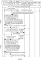
- FIG. 3 is a diagram of a scenario of a bearer control method according to Embodiment 3 of the present invention.
- a service data flow of UE may change.
- the service data flow of the UE may be different at different times.
- An access network access node may perform service identification on a service of the UE, and detect the service data flow of the UE.
- the bearer control method may include:
- the service flow detection report may be generated, and the service flow detection report is reported to the PCRF.
- the access network access node may directly send the service detection report to the PCRF.
- the access network access node may send the service detection report to the PCRF by using the MME. After receiving the service flow detection report, the PCRF may provide the QoS information for the access network access node.
- the access network access node may directly receive the QoS information returned by the PCRF.
- the access network access node may receive the QoS information returned by the PCRF by using the MME.
- another node in a network may also have a service identification function.
- the service flow detection report may also be sent to the PCRF, so that PCRF may provide the QoS information for the access network access node, and subsequently perform matching between the service data flow and the air interface bearer.
- the access network access node may receive the QoS information sent by the PCRF, match the service data flow of the UE with different air interface bearers according to the requirement of the QoS information, that is, match the service data flow that has a same requirement of the QoS information with a same air interface bearer, and establish a mapping relationship between the service data flow, the QoS information, and the air interface bearer.
- a dedicated air interface bearer may need to be modified or added between the access network access node and the UE.
- the access network access node may send the foregoing mapping relationship to the UE in the RRC connection reconfiguration of the UE by using an RRC connection reconfiguration message, where the RRC connection reconfiguration message may include a mapping relationship between the service data flow of the UE and the air interface bearer, and may further include an identifier of an air interface resource allocated by the access network access node to the UE, and the identifier of the air interface resource may be used to indicate an air interface resource that is used by the UE to transmit, on the air interface bearer, the service data flow of the UE.
- the service data flow of the UE may be transmitted on the matching air interface bearer, and in this case, the access network access node may return a QoS information execution response to the PCRF.
- a function of an MME is simplified by performing hierarchical management on a bearer between UE and a network; an access network access node controls transmission of a service data flow on the air interface bearer according to QoS information.
- This enhances management on an air interface resource status by the access network access node, further, improves network resource management efficiency and a network capacity, reduces power consumption, and provides a basis for further evolution of a mobile network.
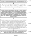
- FIG. 4 is a diagram of a scenario of a bearer control method according to Embodiment 4 of the present invention.
- an access network access node may receive QoS information from a PCRF, and match the service data flow with an air interface bearer according to a requirement of the QoS information, so that uplink data and downlink data are transmitted.
- the access network access node needs to allocate an air interface resource to the UE, and may save, in each node of the network, a context related to the UE, for example, service data flow information and the QoS information.
- intermediate data may be generated in each node of the network, thereby occupying a memory of each node of the network, a port between the nodes of the network, and the like.
- the UE may not have a service data flow that needs to be transmitted in a period of time, that is, the UE is in an idle state.
- an air interface resource occupied by the UE in an idle state and the context of the UE saved in each node of the network may be released. As shown in FIG. 4 , the releasing process may be performed in the following two manners:
- the access network access node detects that the UE does not have a service data flow that needs to be transmitted in the first preset period of time (for example, 2 hours), that is, the UE is in an idle state, or a non-activity timer of the UE expires, the first connection information of the UE may be released, that is, at least one of the mapping relationship between the service data flow of the UE and the air interface bearer in the access network access node or the air interface resource allocated by the access network access node to the UE is released.
- the first preset period of time for example, 2 hours
- the access network access node may send an RRC connection release request to the UE, so as to instruct to release the first connection information between the access network access node and the UE.
- a PDN connection channel between the access network access node and a serving gateway is not released.
- the downlink data may be buffered in the access network access node after a packet data gateway sends the downlink data to the access network access node, and is used to subsequently trigger paging of the UE.
- Manner 2 In a case in which the access network access node detects that the UE does not have a service data flow in the first preset period of time, the RRC connection and the second connection information between the access network access node and the serving gateway are released, the context of the UE is stored in an MME, and the downlink data of the UE is buffered in the serving gateway, where
- the second connection information between the RRC connection of the UE, the access network access node, and the serving gateway may be released, where the second connection information may include the intermediate data generated when the service data flow is transmitted between the access network access node and the serving gateway, the occupied memory, the occupied port, the occupied resource, and the like; and the context of the UE may include at least one of the service data flow of the UE, the QoS information, the air interface resource occupied by the UE, or the location area of the UE.
- the access network access node may send a UE network access context release request to the MME, so as to instruct to release a UE network access context saved in each node of the network, so that each node of the network may have a larger storage capacity.
- the MME may send a channel release request to a core network gateway, so as to instruct the core network gateway to release the second connection information of the UE.
- the core network gateway may return a channel release response to the MME.
- the MME may return a UE network access context release command to the access network access node, so as to instruct the access network access node to release the second connection information of the UE.
- the PDN connection channel between the access network access node and the serving gateway is already released.
- the downlink data may be buffered in the serving gateway after the packet data gateway sends the downlink data to the serving gateway, and is used to subsequently trigger paging of the UE.
- the access network access node when the access network access node sends the UE network access context release request to the MME and when UE network access context is released, the context of the UE, for example, the service data flow and the QoS information, may be stored in the MME.
- two levels of non-activity timers of the UE may be disposed; and if the UE does not perform any activity in a relatively short period of time, the access network access node may release the first connection information in Manner 1; or if the UE does not perform any activity in a relatively long period of time, the access network access node may release the RRC connection and the second connection information in Manner 2.
- first connection information, or an RRC connection and second connection information are released when it is detected that UE is in an idle state, so that network resource management efficiency and a network capacity may be improved and power consumption may be reduced; further, hierarchical management on a bearer between the UE and a network may be implemented in two different release manners, thereby simplifying a function of an MME, and enhancing management on an air interface resource status by an access network access node.
- FIG. 5 is a diagram of a scenario of a bearer control method according to Embodiment 5 of the present invention. As shown in FIG. 5 ,
- a UE in an idle state may regenerate a new service data flow.
- a UE network access context may be re-found according to a service request of the UE, and a connection between the UE and a core network gateway may be recovered.
- a service request procedure of the UE may be performed in the following two manners.
- Manner 1 The access network access node receives a recovery request sent by the UE; the access network access node allocates the new service data flow to the air interface bearer according to a stored context of the UE and according to the QoS information; and the access network access node allocates an air interface resource to the air interface bearer, so that the new service data flow is transmitted on the air interface bearer.
- the access network access node may store the UE network access context, and remain a PDN connection channel between the access network access node and a serving gateway.
- the UE may not send a service request to an MME any longer, and only an RRC connection needs to be recovered between the UE and the access network access node.
- the access network access node may match the new service data flow of the UE with the air interface bearer according to a requirement that is of the QoS information and that is in the UE network access context stored in the access network access node. Refer to a related description of the bearer control method in Embodiment 2 of the present invention.
- a dedicated air interface bearer may need to be modified or established between the UE and the access network access node.
- the UE may transmit, on a corresponding air interface bearer, the service data flow by using a corresponding air interface resource.
- the UE may send a service request to the MME.
- the MME may perform authentication on the UE according to subscription information that is of the UE and that is saved in an HSS, so as to ensure security of a network.
- the MME may send the initial UE network access context establishment request to the access network access node, where the initial UE network access context establishment request may carry the context of the UE that is stored in the MME after a release procedure of an air interface connection is executed in Embodiment 4 of the present invention, for example, service flow information and the QoS information, and may further carry the downlink channel information allocated by the serving gateway to the PDN connection.
- the access network access node may match the new service data flow of the UE with the air interface bearer according to the requirement of the QoS information in the context of the UE.
- a dedicated air interface bearer may need to be modified or established between the UE and the access network access node.
- the UE may send uplink data.
- the access network access node may send the initial UE network access context establishment response to the MME, where the initial UE network access context establishment response may carry the downlink channel information allocated by the MME to the PDN connection.
- the downlink data buffered in the serving gateway may be sent to the UE by using the MME.
- a connection between a core network gateway and the UE is recovered according to different release manners, so that network resource management efficiency and a network capacity may be improved and power consumption may be reduced; further, hierarchical management on a bearer between the UE and a network is implemented, thereby simplifying a function of an MME, and enhancing management on an air interface resource status by an access network access node.
- FIG. 6a to FIG. 6c are flowcharts of a bearer control method according to Embodiment 6 of the present invention.
- management on a location area of UE may include two manners. Specifically, in a process of using the UE, a location may change. Therefore, in a network, the location area of the UE needs to be managed.
- a management manner may include the following two manners:
- the UE For nodes of the network in which the UE is located, such as the access network access node, the MME, and a serving gateway, there may be multiple situations of a location change of the UE. For example, the UE completely moves from an original access network access node to an access network access node that is not under control of the original MME, and the serving gateway also changes. If any one of or multiple of the original access network access node, the MME, and the serving gateway do not change, a location update procedure may be simplified.
- the location area of the UE is managed by the MME, a context of the UE is stored in the MME, and when a location of the UE changes, the bearer control method may include:
- the context of the UE further includes a context generated when the access network access node manages the UE.
- this part of the context needs to be retrieved from the access network access node.
- the location area of the UE is managed by the access network access node
- the MME manages a node identifier when the UE moves between different access network access nodes
- the bearer control method may further include:
- an access network access node 1 may complete registration with an MME 1, the UE accesses the network by using the access network access node 1, and performs transmission of the service data flow.
- the MME 1 may allocate a temporary identifier to the UE, and in addition, the UE may obtain an identifier of the MME 1.
- the UE may send the identifier of the MME 1 to the access network access node 2.
- the access network access node 2 sends, to the MME 2, an identifier of the access network access node 2, the temporary identifier allocated by the MME 1 to the UE, and the identifier of the MME 1. After receiving the identifier of the access network access node 2, the temporary identifier allocated by the MME 1 to the UE, and the identifier of the MME 1, the MME 2 may determine whether the UE is registered with the MME 2.
- the MME 2 may save the context of the UE, and may find, in the context of the UE, the identifier of the access network access node 1, and instruct the corresponding access network access node 1 to delete the location area registered by the UE; or if no, the MME 2 may find the MME 1 according to the received identifier of the MME 1, searches the MME 1 for a registered context of the UE, searches for the identifier of the access network access node 1 by using the context of the UE, and instructs, according to the identifier of the access network access node 1, the corresponding access network access node 1 to delete the location area registered by the UE. Finally, the access network access node 2 updates, according to the location change of the UE, the location area registered by the UE, that is, re-registers a location area for the UE.
- the bearer control method may further include:
- the access network access node may first perform determining once, and determine, according to a determining result, whether the identifier of the MME needs to be sent to the new MME.
- the UE may send the identifier of the MME 1 to the access network access node 2, and the access network access node 2 may determine, according to the received identifier of the MME 1, whether the MME 1 is the MME with which the access network access node 2 is registered.
- the access network access node 2 may send, to the MME 2, the identifier of the access network access node 2 and the temporary identifier allocated by the MME 1 to the UE, and after receiving the identifier of the access network access node 2 and the temporary identifier allocated by the MME 1 to the UE, the MME 2 searches, by using the context that is of the UE and that is saved in the MME 2, for the identifier of the access network access node 1, and instructs, by using the identifier, the corresponding access network access node 1 to delete the location area registered by the UE; or if no, the access network access node 2 may send, to the MME 2, the identifier of the access network access node 2, the temporary identifier allocated by the MME 1 to the UE, and the identifier of the MME 1, and the MME 2 finds the corresponding MME 1 according to the received identifier of the MME 1, searches the registered context of the UE from the MME 1, searches the identifier of the access network access node
- the access network access node may retrieve the context of the UE from the MME, where the context may include a mobility context used when the access network access node manages the UE, that is, a location area originally allocated to the UE; and process a location update request, or re-allocate a location area to the UE according to the location of the UE.
- the location area of the UE may be managed in Manner 1.
- the UE may send a location update message to the MME 1.
- the MME 1 may establish a PDN connection channel between the MME 1, a serving gateway 1, and a packet data gateway; the location area of the UE is updated in an HSS; the location area of the UE originally registered, by the MME 2, in HSS is canceled; if the MME 2 stores the context of the UE, the MME 1 may obtain the context of the UE from the MME 2, or if the access network access node 2 stores the context of the UE, the MME 2 needs to retrieve the context of the UE from the access network access node 2, and transfer the context to the MME 1; a PDN session connection between the MME 2 and a serving gateway 2 is deleted.
- the location area of the UE may be managed in Manner 2.
- the UE may initiate a paging area update on the access network access node 1, and the access network access node 1 initiates access node update on the MME 1.
- a node identifier of the access network access node may be carried, and the MME 1 may update the access network access node by managing the node identifier.
- the access network access node 1 may manage the paging area update of the UE.
- the PDN connection channel between the MME and a core network gateway does not need to be updated. Therefore, a procedure may be simplified.
- the context of the UE does not need to be transferred between the MMEs.
- the context of the UE may be directly used. If the access network access node stores the context of the UE, the MME may find the corresponding access network access node and retrieve the context of the UE for subsequent management.
- the bearer control method in this embodiment may further have many possible implementation manners according to a specific situation of the UE location update, a storage location of the context of the UE, and a management manner for the location area of the UE.
- a function of an MME is simplified by performing hierarchical management on a bearer between UE and a network. This enhances management on a context of the UE by an access network access node, further, improves network resource management efficiency and a network capacity, reduces power consumption, and provides a basis for further evolution of a mobile network.
- FIG. 7 is a diagram of a scenario of a bearer control method according to Embodiment 7 of the present invention. As shown in FIG. 7 , after a location of UE is updated, a new service data flow is generated, and paging of the UE needs to be initiated.
- downlink data of the UE may be buffered in an access network access node, or may be buffered in a serving gateway.
- a paging procedure may include: receiving, by the access network access node, the downlink data of the UE, or receiving downlink data sent by the serving gateway; and initiating paging of the UE in a location area registered by the UE.
- the paging procedure may further include: receiving, by an MME, the downlink data of the UE from the serving gateway, and sending a paging message to the access network access node, so as to instruct the access network access node to initiate paging of the UE; or receiving, by the access network access node, the paging message, and initiating paging of the UE in the location area registered by the UE.
- the serving gateway may buffer the downlink data and send a downlink data notification to the MME; after receiving the downlink data notification, the MME may send the paging message to the access network access node, so as to instruct the access network access node to page the UE.
- the MME may add the location area registered by the UE to the paging message sent by the access network access node; the access network access node may page the UE in a corresponding cell according to the location area registered by the UE.
- a paging area in the access network access node is managed by the access network access node, and the MME manages a node identifier when the UE moves between different access network access nodes; the MME sends the paging message to the access network access node, and the access network access node may page the UE in a corresponding cell according to the paging area registered by the UE.
- the release Manner 1 in the foregoing embodiment of the present invention is used, only first connection information between the UE and the access network access node is released, and the access network access node may receive the downlink data and buffer the downlink data. If management on the location area of the UE is performed in Manner 1 in the bearer control method in Embodiment 6 of the present invention and is completely performed by the MME, the access network access node may page the UE in a corresponding cell according to the location area registered by the UE.
- a paging area in the access network access node is managed by the access network access node, and the MME manages a node identifier when the UE moves between different access network access nodes; the access network access node may page the UE in a corresponding cell according to the paging area registered by the UE.
- a function of an MME is simplified by performing hierarchical management on a bearer between UE and a network. This enhances management on a context of the UE by an access network access node, further, improves network resource management efficiency and a network capacity, reduces power consumption, and provides a basis for further evolution of a mobile network.
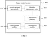
- FIG. 8 is a structural block diagram of a bearer control system according to Embodiment 8 of the present invention.
- the bearer control system 800 may mainly include:
- network access registration first needs to be performed, and authentication is performed on the UE by obtaining subscription information between the UE and the network.
- the subscription information may be saved in a home subscriber server (Home Subscriber Server, HSS for short).
- the foregoing network access registration process of the UE is an attach procedure. After the attach procedure, the UE already accesses the network.
- the establishment module 840 further needs to add a PDN policy session, so as to establish a PDN connection between the UE and the network.
- the HSS is a database storing user subscription information, and the subscription information may include: a user category, a service use right, a quality-of-service class, a charging mode, and the like that are negotiated by the user with an operator.
- the UE may receive the QoS information from a policy and charging rule function (Policy and Charing Rule Function, PCRF) decision point by using the PDN connection.
- the transmission module 850 may identify the service data flow of the UE according to a requirement of the QoS information.
- a data path of a granularity of the foregoing PDN connection may include an air interface bearer part and a transmission tunnel part.
- the air interface bearer is a transmission path between the UE and the access network access node 810 (for example, an eNodeB).
- the transmission module 850 may identify the service data flow of the UE according to the requirement of the received QoS information, and service data flows that do not meet the requirement of the QoS information are separately matched with different air interface bearers.
- the access network access node 810 may separately allocate an air interface resource to different air interface bearers, so as to transmit the service data flow of the UE.
- the transmission tunnel part is the transmission tunnel between the access network access node 810 and the PCRF, may be used to transmit the service data flow between the access network access node and the PCRF, and does not require that the service data flow is identified according to the requirement of the QoS information.
- the access network access node 810 may directly send, by using a transmission module 850 to a packet data network, the service data flow that is received from the UE by using the air interface bearer.
- the data path of the granularity of the PDN connection established between the access network access node 810 and the core network gateway 830 bears all uplink data and downlink data of the PDN connection of the UE.
- context information of the UE saved in each network node may be deleted and released on the data path, so as to improve network resource utilization.
- the data path may be reserved.
- the data path of the granularity of the PDN connection that is of the UE and that is between the access network access node 810 in which the UE initiates the service request and the core network gateway 830 may be recovered.
- a function of an MME is simplified by performing hierarchical management on a bearer between UE and a network; an access network access node controls transmission of a service data flow on the air interface bearer according to QoS information.
- This enhances management on an air interface resource status by the access network access node, further, improves network resource management efficiency and a network capacity, reduces power consumption, and provides a basis for further evolution of a mobile network.
- FIG. 9 is a structural block diagram of a bearer control system according to Embodiment 9 of the present invention. Components that have a same reference sign in FIG. 9 and FIG. 8 have a same function. For brevity, detailed descriptions about these components are omitted.
- the establishment module 840 may specifically include: an adding unit 910, configured to: add a PDN connection policy session to an access network control session between the access network access node and a PCRF; or add the PDN connection policy session between the access network access node and the MME and/or between the MME and the PCRF.
- each node in a network may save identification information of the UE.
- each node in the network may further save identification information of a PDN.
- the access network access node 810 or the MME 820 may find a corresponding PCRF in the network by using the saved identification information of the UE and the saved identification information of the PDN, and initiate establishing of the PDN connection policy session.
- the adding unit 910 may add the PDN connection policy session to the access network control session between the access network access node 810 and the PCRF. If all PDN connections of the UE are respectively served by multiple PCRFs, the adding unit 910 may add the PDN connection policy session between the access network access node 810 and the MME 820, and the MME 820 and the PCRF establish the PDN connection policy session between the MME 820 and the PCRF.
- the access network access node 810 may include:
- the receiving unit 920 of the access network access node 810 may directly receive the QoS information from the PCRF by using the foregoing transmission path, or may receive the QoS information from the PCRF by using the MME 820, so that the access network access node 810 may subsequently identify a service data flow of the UE according to the QoS information, and complete the radio resource control (Radio Resource Control, RRC) connection reconfiguration.
- RRC Radio Resource Control
- the reconfiguration unit 930 may identify the service data flow of the UE according to a requirement of the QoS information, establish a mapping relationship between different service data flows that meet different requirements of the QoS information and different air interface bearers, and allocate, to different air interface bearers, the air interface resource, that is, the air interface resource used when different service data flows are transmitted on different air interface bearers.
- the access network access node 810 may further include:
- the RRC connection reconfiguration message includes the mapping relationship between the service data flow of the UE and the air interface bearer and an identifier of the air interface resource, and the identifier of the air interface resource is used to indicate the air interface resource used by the UE to transmit, on the air interface bearer, the service data flow.
- the receiving unit 920 may receive the RRC connection reconfiguration success response from the UE, so that the RRC connection reconfiguration process is completed.
- the access network access node 810 may further obtain the QoS information (such as bandwidth, a priority, a delay, and a packet loss rate) of the service data flow by using uplink and downlink data flows that are of the UE and that are identified by the access network access node 810. Further, if the UE transmits the service data flow by using the foregoing data path, a node in a network (for example, the MME 820) may save a context of the UE, including the mapping relationship that is between the service data flow and the QoS information and that is in the context.
- the QoS information such as bandwidth, a priority, a delay, and a packet loss rate
- the access network access node 810 may obtain, from the MME 820, the mapping relationship that is between the service data flow and the QoS information and that is in the context, allocate an uplink resource and downlink resources (especially air interface radio resources) to the UE, map the uplink and downlink resources to the air interface bearer, and send, by using the RRC connection reconfiguration message to the UE, the mapping relationship between the service data flow and the air interface bearer and the air interface resource that is used when the UE transmits, on the air interface bearer, the service data flow.
- an uplink resource and downlink resources especially air interface radio resources
- the core network gateway 830 may include a serving gateway SGW and/or a packet data gateway PGW.
- the MME 820 may specifically include:
- the access network access node 810 may further include a modification unit 980.
- an initial air interface bearer may be established between the UE and the access network access node, where the initial air interface bearer may include a dedicated air interface bearer.
- the modification unit 980 may add or modify the dedicated air interface bearer according to a requirement of the QoS information, where the dedicated air interface bearer is established according to at least one of a scheduling priority, a delay, a packet loss rate, or a bandwidth requirement in the QoS information, and the dedicated air interface bearer carries matching information of the service data flow and the dedicated air interface bearer.
- a function of an MME is simplified by performing hierarchical management on a bearer between UE and a network; an access network access node controls transmission of a service data flow on the air interface bearer according to QoS information.
- This enhances management on an air interface resource status by the access network access node, further, improves network resource management efficiency and a network capacity, reduces power consumption, and provides a basis for further evolution of a mobile network.
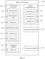
- FIG. 10 is a structural block diagram of a bearer control system according to Embodiment 10 of the present invention.
- a service data flow of UE may change.
- the service data flow of the UE may be different at different times.
- An access network access node 810 may perform service identification on a service of the UE, and detect the service data flow of the UE.
- the access network access node 810 of the bearer control system 1000 may further include an allocation unit 1010.
- the access network access node 810 detects the service data flow of the UE,
- a function of an MME is simplified by performing hierarchical management on a bearer between UE and a network; an access network access node controls transmission of a service data flow on the air interface bearer according to QoS information.
- This enhances management on an air interface resource status by the access network access node, further, improves network resource management efficiency and a network capacity, reduces power consumption, and provides a basis for further evolution of a mobile network.
- FIG. 11 is a structural block diagram of a bearer control system according to Embodiment 11 of the present invention.
- an access network access node 810 may receive QoS information from a PCRF, and match the service data flow with an air interface bearer according to a requirement of the QoS information, so that uplink data and downlink data are transmitted.
- the access network access node 810 needs to allocate an air interface resource to the UE, and may save, in each node of the network, a context related to the UE, for example, service data flow information and the QoS information.
- intermediate data may be generated in each node of the network, thereby occupying a memory of each node of the network, a port between the nodes of the network, and the like.
- the UE may not have a service data flow that needs to be transmitted in a period of time, that is, the UE is in an idle state.
- an air interface resource occupied by the UE in an idle state and the context of the UE saved in each node of the network may be released.
- the access network access node 810 may further include a releasing unit 1110.
- the releasing unit 1110 is configured to: release first connection information between the access network access node and the UE, store the context of the UE in the access network access node, and buffer the downlink data of the UE in the access network access node, where the first connection information is at least one of the mapping relationship between the service data flow of the UE and the air interface bearer, or the air interface resource allocated by the access network access node to the UE.
- the releasing unit 1110 is further configured to: release second connection information between an RRC connection, the access network access node, and a serving gateway, store the context of the UE in an MME, and buffer the downlink data of the UE in the serving gateway, where
- UE in an idle state may regenerate a new service data flow.
- a UE network access context may be re-found according to a service request of the UE, and a connection between the UE and a core network gateway 830 may be recovered.
- the receiving unit 920 is further configured to receive a recovery request sent by the UE.
- the allocation unit 1010 is further configured to allocate the new service data flow to the air interface bearer according to the stored context of the UE and the QoS information.
- the allocation unit 1010 is further configured to allocate the air interface resource to the air interface bearer, so that the new service data flow is transmitted on the air interface bearer.
- a releasing unit when it is detected that UE is in an idle state, a releasing unit releases first connection information, or an RRC connection and second connection information.
- a connection between the UE and a core network gateway is recovered in different release manners, so that network resource management efficiency and a network capacity may be improved and power consumption may be reduced; further, hierarchical management on a bearer between the UE and a network may be implemented in two different release manners, thereby simplifying a function of an MME, and enhancing management on an air interface resource status by an access network access node.
- a location area of UE may include two manners. Specifically, in a process of using the UE, a location may change. Therefore, in a network, the location area of the UE needs to be managed.
- a management manner may include the following two manners:
- nodes of the network in which the UE is located such as the access network access node 810 and the MME 820
- there may be multiple situations of a location change of the UE For example, the UE completely moves from an original access network access node to an access network access node that is not under control of the original MME, and the serving gateway also changes. If any one of or multiple of the original access network access node, the MME, and the serving gateway do not change, a location update procedure may be simplified.
- a new MME 1201 to which the UE moves may include a retrieving unit 1210 and an updating unit 1220. If a location area of the UE is managed by the MME, a context of the UE is stored in the MME, and when the location of the UE changes,
- the retrieving unit 1210 is configured to retrieve the context of the UE from the MME.
- the updating unit 1220 is connected to the retrieving unit 1210, and is configured to update, according to a location change of the UE, a location area registered by the UE.
- the location area of the UE is managed by the access network access node
- the MME manages a node identifier when the UE moves between different access network access nodes
- a new access network access node 1202 to which the UE moves may include:
- the location area of the UE is managed by the access network access node
- the MME manages a node identifier when the UE moves between different access network access nodes
- the new access network access node 1202 to which the UE moves may further include:
- a new service data flow is generated, and paging of the UE needs to be initiated.
- downlink data of the UE may be buffered in an access network access node, or may be buffered in a serving gateway.
- the receiving unit 920 of the access network access node is further configured to: receive the downlink data of the UE, or receive downlink data sent by the serving gateway; and initiate paging of the UE in the location area registered by the UE.
- the receiving unit 950 of the MME is further configured to receive the downlink data of the UE from the serving gateway; the sending unit 970 of the MME is further configured to send a paging message to the access network access node, so as to instruct the access network access node to initiate paging of the UE; and the receiving unit 920 of the access network access node is further configured to: receive the paging message, and initiate paging of the UE in the location area registered by the UE.
- a function of an MME is simplified by performing hierarchical management on a bearer between UE and a network. This enhances management on a context of the UE by an access network access node, further, improves network resource management efficiency and a network capacity, reduces power consumption, and provides a basis for further evolution of a mobile network.
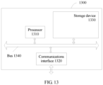
- FIG. 13 is a structural block diagram of a bearer control system 1300 according to Embodiment 13 of the present invention.
- the bearer control system 1300 may be a host server having computing power, a personal computer PC, a portable computer or terminal, or the like.
- a specific embodiment of the present invention imposes no limitation on specific implementation of a computing node.
- the bearer control system 1300 includes a processor (processor)1310, a communications interface (Communications Interface) 1320, a memory (memory) 1330, and a bus 1340.
- the processor 1310, the communications interface 1320, and the memory 1330 complete communication between them by using the bus 1340.
- the communications interface 1320 is configured to communicate with a network device, where the network device includes a virtual machine management center, a shared storage, and the like.
- the processor 1310 is configured to execute a program.
- the processor 1310 may be a central processing unit CPU or an application specific integrated circuit ASIC (Application Specific Integrated Circuit), or may be configured to be one or more integrated circuits that implement this embodiment of the present invention.
- ASIC Application Specific Integrated Circuit
- the memory 1330 is configured to store a file.
- the memory 1330 may include a high-speed RAM memory, and may further include a non-volatile memory (non-volatile memory), for example, at least one disk storage device.
- the memory 1330 may be a storage device array.
- the memory 1330 may be divided into blocks, and the blocks may form a virtual volume according to a specific rule.
- the foregoing program may be program code that includes a computer operation instruction.
- the program is applied to a network architecture supporting multiple access technologies, and may be specifically used to:
- the establishing a packet data network PDN connection when a terminal device UE accesses a network includes:
- the foregoing program is further configured to:
- the performing, by the access network access node, radio resource control protocol RRC connection reconfiguration includes:
- the core network gateway includes a serving gateway and/or a packet data gateway, and before the transmitting the service data flow by using a transmission tunnel between the access network access node and a core network gateway, the foregoing program is further configured to:
- the foregoing program is further configured to:
- the foregoing program is further configured to:
- the foregoing program is further configured to:
- the foregoing program is further configured to:
- the foregoing program is further configured to: add or modify, by the access network access node, a dedicated air interface bearer according to the QoS information, where the dedicated air interface bearer is established according to at least one of a scheduling priority, a delay, a packet loss rate, or a bandwidth requirement in the QoS information, and the dedicated air interface bearer carries matching information of the service data flow and the dedicated air interface bearer.
- a location area of the UE is managed by an MME, a context of the UE is stored in the MME, and when a location of the UE changes, the following steps are further included:
- the location area of the UE is managed by the access network access node
- the MME manages a node identifier when the UE moves between different access network access nodes, and when the location of the UE changes, the following steps are further included:
- the location area of the UE is managed by the access network access node
- the MME manages a node identifier when the UE moves between different access network access nodes, and when the location of the UE changes, the following steps are further included:
- the foregoing program is further configured to: receive, by the access network access node, the downlink data of the UE, or receive downlink data sent by the serving gateway; and initiate paging of the UE in the location area registered by the UE.
- the foregoing program is further configured to:
- the computer software product is generally stored in a computer readable non-volatile storage medium and includes several instructions for instructing a computer device (which may be a personal computer, a server, or a network device, and the like) to perform all or some steps of the methods described in the embodiments of the present invention.
- the foregoing storage medium includes any medium that can store program code, such as a USB flash drive, a removable hard disk, a read-only memory (ROM, Read-Only Memory), a random access memory (RAM, Random Access Memory), a magnetic disk, or an optical disc.
- program code such as a USB flash drive, a removable hard disk, a read-only memory (ROM, Read-Only Memory), a random access memory (RAM, Random Access Memory), a magnetic disk, or an optical disc.
Landscapes
- Engineering & Computer Science (AREA)
- Computer Networks & Wireless Communication (AREA)
- Signal Processing (AREA)
- Quality & Reliability (AREA)
- Mobile Radio Communication Systems (AREA)
Claims (9)
- Trägersteuerverfahren, angewendet auf eine Netzarchitektur, die Mehrfachzugriffstechnologien unterstützt, umfassend:Senden, durch eine Richtlinien-und-Abrechnungsregel-Funktion unter Verwendung einer Mobilitätsverwaltungsentität, von Dienstgüte- bzw. QoS-Informationen an einen Zugangsnetzzugangsknoten;Empfangen (210), durch den Zugangsnetzzugangsknoten, der QoS-Informationen von der Richtlinien-und-Abrechnungsregel-Funktion;Identifizieren, durch den Zugangsnetzzugangsknoten, eines Dienstdatenflusses eines Benutzergeräts, UE;Abgleichen, durch den Zugangsnetzzugangsknoten gemäß den QoS-Informationen, des Dienstdatenflusses des UE mit einem Funkschnittstellenträger zwischen dem UE und dem Zugangsnetzzugangsknoten;Durchführen (220), durch den Zugangsnetzzugangsknoten, einer Funkressourcensteuerungs- bzw. RRC-Verbindungsrekonfiguration zwischen dem UE unddem Zugangsnetzzugangsknoten gemäß den QoS-Informationen unter Verwendung einer Rekonfigurationsnachricht, wobei das Durchführen, durch den Zugangsnetzzugangsknoten, einer Funkressourcensteuerungsprotokoll- bzw. RRC-Verbindungsrekonfiguration gemäß den QoS-Informationen Folgendes umfasst:- Senden (221), durch den Zugangsnetzzugangsknoten, einer RRC-Verbindungsrekonfigurationsnachricht an das UE; und- Empfangen (222), durch den Zugangsnetzzugangsknoten, einer RRC-Verbindungsrekonfigurationserfolgsantwort von dem UE; wobeidie Rekonfigurationsnachricht eine Abbildungsbeziehung zwischen dem Dienstdatenfluss des UE und dem Funkschnittstellenträger und eine Kennung des Funkschnittstellenträgers beinhaltet und die Kennung dazu verwendet wird, die Funkschnittstellenressource anzugeben, die durch das UE zum Übertragen des Dienstdatenflusses auf dem Funkschnittstellenträger verwendet wird, und wobei die Funkschnittstellenressource dem Funkschnittstellenträger durch den Zugangsnetzzugangsknoten zugewiesen wird; undÜbertragen (120), durch den Zugangsnetzzugangsknoten, von Downlink-Daten des Dienstdatenflusses des UE auf dem Funkschnittstellenträger gemäß den empfangenen QoS-Informationen und Übertragen, durch den Zugangsnetzzugangsknoten, von Uplink-Daten des Dienstdatenflusses unter Verwendung eines Übertragungstunnels zwischen dem Zugangsnetzzugangsknoten und einem Kernnetz-Gateway.
- Trägersteuerverfahren nach Anspruch 1, ferner umfassend, vor dem Schritt der QoS-Informationen von der Richtlinien-und-Abrechnungsregel-Funktion:
Aufbauen (100) einer Paketdatennetz- bzw. PDN-Verbindung, wenn ein Benutzergerät UE auf ein Netz zugreift. - Trägersteuerverfahren nach Anspruch 2, wobei das Aufbauen (100) einer PDN-Verbindung, wenn ein UE auf ein Netz zugreift, Folgendes umfasst:
Hinzufügen der PDN-Verbindungsrichtliniensitzung zwischen der Mobilitätsverwaltungsentität und der Richtlinien-und-Abrechnungsregel-Funktion. - Trägersteuerverfahren nach einem der Ansprüche 1 bis 3, wobei das Verfahren, wenn der Zugangsnetzzugangsknoten den Dienstdatenfluss des UE detektiert, ferner Folgendes umfasst:Senden (300), durch den Zugangsnetzzugangsknoten unter Verwendung der Mobilitätsverwaltungsentität, einer Dienstdetektionsmeldung an die Richtlinien-und-Abrechnungsregel-Funktion und Empfangen (310), unter Verwendung der Mobilitätsverwaltungsentität, der durch die Richtlinien-und-Abrechnungsregel-Funktion zurückgegebenen QoS-Informationen; undZuweisen (320), durch den Zugangsnetzzugangsknoten, des Dienstdatenflusses des UE zu dem Funkschnittstellenträger gemäß den QoS-Informationen.
- Trägersteuerverfahren nach einem der Ansprüche 1 bis 4, wobei das Verfahren in einem Fall, in dem der Zugangsnetzzugangsknoten detektiert, dass das UE in einer ersten vorgegebenen Zeitdauer keinen Dienstdatenfluss aufweist, ferner Folgendes umfasst:Freigeben von ersten Verbindungsinformationen zwischen dem Zugangsnetzzugangsknoten und dem UE, Speichern eines Kontexts des UE in dem Zugangsnetzzugangsknoten und Puffern von Downlink-Daten des UE in dem Zugangsnetzzugangsknoten, wobeies sich bei den ersten Verbindungsinformationen um die Abbildungsbeziehung zwischen dem Dienstdatenfluss des UE und dem Funkschnittstellenträger und/oder die Funkschnittstellenressource, die dem UE durch den Zugangsnetzzugangsknoten zugewiesen wird, handelt.
- Trägersteuerverfahren nach einem der Ansprüche 1 bis 4, wobei das Verfahren in einem Fall, in dem der Zugangsnetzzugangsknoten detektiert, dass das UE in der ersten vorgegebenen Zeitdauer keinen Dienstdatenfluss aufweist, ferner Folgendes umfasst:Freigeben einer RRC-Verbindung und von zweiten Verbindungsinformationen, die zwischen dem Zugangsnetzzugangsknoten und dem bedienenden Gateway vorliegen,Speichern des Kontexts des UE in der Mobilitätsverwaltungsentität und Puffern der Downlink-Daten des UE in dem bedienenden Gateway, wobeies sich bei den zweiten Verbindungsinformationen um Zwischendaten, die bei Übertragung des Dienstdatenflusses zwischen dem Zugangsnetzzugangsknoten und dem bedienenden Gateway erzeugt werden, und/oder einen belegten Speicher und/oder einen belegten Port und/oder eine belegte Rechenressource handelt; undder Kontext des UE den Dienstdatenfluss des UE und/oder die QoS-Informationen und/oder die durch das UE belegte Funkschnittstellenressource und/oder einen Standortbereich des UE umfasst.
- Trägersteuerverfahren nach einem der Ansprüche 1 bis 6, das ferner Folgendes umfasst: Hinzufügen oder Modifizieren, durch den Zugangsnetzzugangsknoten, eines dedizierten Funkschnittstellenträgers gemäß den QoS-Informationen, wobei der dedizierte Funkschnittstellenträger gemäß einer Planungspriorität und/oder einer Verzögerung und/oder einer Paketverlustrate und/oder einer Bandbreitenanforderung in den QoS-Informationen eingerichtet wird und der dedizierte Funkschnittstellenträger übereinstimmende Informationen des Dienstdatenflusses und des dedizierten Funkschnittstellenträgers führt.
- Trägersteuerverfahren nach einem der Ansprüche 1 bis 7, wobei der Dienstdatenfluss Folgendes umfasst: unterschiedliche Dienstdatenflüsse, die eine gleiche Anforderung der QoS-Informationen erfüllen.
- Trägersteuersystem, angewandt auf eine Netzarchitektur, die Mehrfachzugriffstechnologien unterstützt, umfassend: einen Zugangsnetzzugangsknoten, eine Mobilitätsverwaltungsentität, ein Kernnetz-Gateway und eine Richtlinien-und-Abrechnungsregel-Funktion;
wobei die Richtlinien-und-Abrechnungsregel-Funktion und der Zugangsnetzzugangsknoten dazu ausgelegt sind, die Verfahrensschritte der Richtlinien-und-Abrechnungsregel-Funktion bzw. des Zugangsnetzzugangsknotens nach einem der Ansprüche 1 bis 8 durchzuführen.
Priority Applications (1)
| Application Number | Priority Date | Filing Date | Title |
|---|---|---|---|
| EP23194589.0A EP4304294A3 (de) | 2014-04-21 | 2014-04-21 | Trägersteuerungsverfahren und -system |
Applications Claiming Priority (1)
| Application Number | Priority Date | Filing Date | Title |
|---|---|---|---|
| PCT/CN2014/075819 WO2015161411A1 (zh) | 2014-04-21 | 2014-04-21 | 承载控制方法及系统 |
Related Child Applications (2)
| Application Number | Title | Priority Date | Filing Date |
|---|---|---|---|
| EP23194589.0A Division-Into EP4304294A3 (de) | 2014-04-21 | 2014-04-21 | Trägersteuerungsverfahren und -system |
| EP23194589.0A Division EP4304294A3 (de) | 2014-04-21 | 2014-04-21 | Trägersteuerungsverfahren und -system |
Publications (3)
| Publication Number | Publication Date |
|---|---|
| EP3128802A1 EP3128802A1 (de) | 2017-02-08 |
| EP3128802A4 EP3128802A4 (de) | 2017-04-05 |
| EP3128802B1 true EP3128802B1 (de) | 2023-10-04 |
Family
ID=54331555
Family Applications (2)
| Application Number | Title | Priority Date | Filing Date |
|---|---|---|---|
| EP14890344.6A Active EP3128802B1 (de) | 2014-04-21 | 2014-04-21 | Trägersteuerungsverfahren und system |
| EP23194589.0A Pending EP4304294A3 (de) | 2014-04-21 | 2014-04-21 | Trägersteuerungsverfahren und -system |
Family Applications After (1)
| Application Number | Title | Priority Date | Filing Date |
|---|---|---|---|
| EP23194589.0A Pending EP4304294A3 (de) | 2014-04-21 | 2014-04-21 | Trägersteuerungsverfahren und -system |
Country Status (4)
| Country | Link |
|---|---|
| US (3) | US10201024B2 (de) |
| EP (2) | EP3128802B1 (de) |
| CN (2) | CN110337150B (de) |
| WO (1) | WO2015161411A1 (de) |
Families Citing this family (19)
| Publication number | Priority date | Publication date | Assignee | Title |
|---|---|---|---|---|
| EP3105974B1 (de) * | 2014-02-14 | 2020-08-12 | Telefonaktiebolaget LM Ericsson (publ) | Pcrf-unterstützte apn-auswahl |
| WO2015191835A1 (en) | 2014-06-11 | 2015-12-17 | Convida Wireless, Llc | Mapping service for local content redirection |
| US20180167854A1 (en) * | 2014-09-25 | 2018-06-14 | Sharp Kabushiki Kaisha | Terminal device, mme, and control method |
| EP3836586A1 (de) | 2015-04-22 | 2021-06-16 | Convida Wireless, LLC | Ermöglichung der kleindatennutzung in 3gpp-netzwerken |
| CN107295452B (zh) * | 2016-03-30 | 2021-06-08 | 中兴通讯股份有限公司 | 一种信息通知方法和装置 |
| CN107295575B (zh) * | 2016-04-01 | 2020-02-28 | 中兴通讯股份有限公司 | 一种服务质量的控制方法和装置 |
| US10277515B2 (en) * | 2016-04-04 | 2019-04-30 | Qualcomm Incorporated | Quality of service (QOS) management in wireless networks |
| JP2019149588A (ja) * | 2016-07-04 | 2019-09-05 | シャープ株式会社 | 端末装置、制御装置、ゲートウェイ、及び通信制御方法 |
| JP2019145864A (ja) * | 2016-07-04 | 2019-08-29 | シャープ株式会社 | 端末装置、制御装置、ゲートウェイ、及び通信制御方法 |
| CN114760710B (zh) | 2016-08-01 | 2024-12-13 | 三星电子株式会社 | 用于管理无线通信网络中的数据通信的方法和设备 |
| FR3058863B1 (fr) * | 2016-11-14 | 2019-07-05 | Airbus Defence And Space Sas | Equipement mandataire dans un systeme de telecommunication cellulaire |
| CN115460650B (zh) | 2017-02-06 | 2024-11-29 | 三星电子株式会社 | 基站、接入和移动性管理功能实体及其方法 |
| KR102395384B1 (ko) * | 2017-03-20 | 2022-05-10 | 삼성전자 주식회사 | 셀룰러망의 효율적 pdu 세션 활성화 및 비활성화 방안 |
| US10251147B2 (en) * | 2017-03-20 | 2019-04-02 | Samsung Electronics Co., Ltd. | Method for supporting efficient PDU session activation and deactivation in cellular networks |
| US10644974B2 (en) | 2017-05-04 | 2020-05-05 | At&T Intellectual Property I, L.P. | Measurements and radio link monitoring in a wireless communications system |
| US11032744B2 (en) | 2017-05-04 | 2021-06-08 | At&T Intellectual Property I, L.P. | Inter-distributed unit beam switch procedure triggered by radio link interruption |
| US10499398B2 (en) | 2017-09-29 | 2019-12-03 | At&T Intellectual Property I, L.P. | Facilitating mobile device-assisted mobility enhancement to improve user plane interruption time |
| CN110048861B (zh) * | 2018-01-17 | 2021-01-29 | 华为技术有限公司 | 一种业务数据流处理方法及其相关设备 |
| CN114629544B (zh) * | 2022-03-09 | 2023-06-20 | 成都天奥集团有限公司 | 一种融合5g技术实现测控的方法 |
Citations (2)
| Publication number | Priority date | Publication date | Assignee | Title |
|---|---|---|---|---|
| US20130287012A1 (en) * | 2012-04-27 | 2013-10-31 | Interdigital Patent Holdings, Inc. | Method and apparatus for optimizing proximity data path setup |
| US20140018067A1 (en) * | 2012-07-14 | 2014-01-16 | Tekelec, Inc. | Methods, systems, and computer readable media for policy-based local breakout (lbo) |
Family Cites Families (14)
| Publication number | Priority date | Publication date | Assignee | Title |
|---|---|---|---|---|
| CN101374260B (zh) * | 2007-08-22 | 2011-11-09 | 华为技术有限公司 | Pcc规则和承载关联的实现方法、装置和系统 |
| KR101375474B1 (ko) * | 2007-09-13 | 2014-03-20 | 삼성전자주식회사 | 인터넷 프로토콜을 이용하는 통신 장치 및 방법 |
| US20090190471A1 (en) * | 2008-01-10 | 2009-07-30 | Mahendran Arungundram C | Method and Apparatus for Optimized Session Setup with Network-Initiated QoS Policy Control |
| CN101730150B (zh) * | 2009-01-19 | 2013-08-07 | 中兴通讯股份有限公司 | 业务流迁移时对网络资源进行控制的方法 |
| CN101854734B (zh) * | 2009-03-30 | 2013-08-28 | 华为技术有限公司 | 释放接入连接的方法、装置、策略控制实体及系统 |
| US8498208B2 (en) * | 2009-07-20 | 2013-07-30 | Qualcomm Incorporated | Turning on flows in network initiated QoS |
| CN101990247B (zh) * | 2009-08-07 | 2013-08-28 | 华为技术有限公司 | 数据传输方法、装置和通信系统 |
| WO2011120235A1 (zh) * | 2010-04-02 | 2011-10-06 | 华为技术有限公司 | Sae架构下实现业务数据流旁路的方法、装置及系统 |
| CN102238574B (zh) * | 2010-04-27 | 2016-06-15 | 中兴通讯股份有限公司 | 一种用户状态改变的通知方法及系统 |
| US20110310737A1 (en) * | 2010-06-21 | 2011-12-22 | Qualcomm Incorporated | Method and apparatus for qos context transfer during inter radio access technology handover in a wireless communication system |
| EP2445266B1 (de) * | 2010-10-25 | 2016-03-16 | Alcatel Lucent | Steuerung der Zugangsnetzwerk-/Zugangstechnologieauswahl zum Routen eines IP-Verkehrs durch ein Benutzergerät sowie QoS-Unterstützung in einem Kommunikationssystem mit Mehrfachzugriff |
| CN102761958B (zh) * | 2011-04-28 | 2017-09-22 | 中兴通讯股份有限公司 | 一种支持多接入的承载管理方法和系统 |
| US9973966B2 (en) * | 2013-01-11 | 2018-05-15 | Interdigital Patent Holdings, Inc. | User-plane congestion management |
| US10264491B2 (en) * | 2014-04-01 | 2019-04-16 | Nokia Solutions And Networks Oy | Enhanced quality of service class identifier modification |
-
2014
- 2014-04-21 EP EP14890344.6A patent/EP3128802B1/de active Active
- 2014-04-21 WO PCT/CN2014/075819 patent/WO2015161411A1/zh not_active Ceased
- 2014-04-21 CN CN201910467782.2A patent/CN110337150B/zh active Active
- 2014-04-21 EP EP23194589.0A patent/EP4304294A3/de active Pending
- 2014-04-21 CN CN201480000646.8A patent/CN105379402B/zh active Active
-
2016
- 2016-10-20 US US15/298,463 patent/US10201024B2/en active Active
-
2019
- 2019-01-09 US US16/243,516 patent/US10772136B2/en active Active
-
2020
- 2020-08-28 US US17/006,206 patent/US11382146B2/en active Active
Patent Citations (2)
| Publication number | Priority date | Publication date | Assignee | Title |
|---|---|---|---|---|
| US20130287012A1 (en) * | 2012-04-27 | 2013-10-31 | Interdigital Patent Holdings, Inc. | Method and apparatus for optimizing proximity data path setup |
| US20140018067A1 (en) * | 2012-07-14 | 2014-01-16 | Tekelec, Inc. | Methods, systems, and computer readable media for policy-based local breakout (lbo) |
Also Published As
| Publication number | Publication date |
|---|---|
| CN105379402B (zh) | 2019-06-11 |
| US11382146B2 (en) | 2022-07-05 |
| US10772136B2 (en) | 2020-09-08 |
| CN110337150A (zh) | 2019-10-15 |
| EP4304294A3 (de) | 2024-03-27 |
| EP4304294A2 (de) | 2024-01-10 |
| US20200396777A1 (en) | 2020-12-17 |
| US20190150207A1 (en) | 2019-05-16 |
| US10201024B2 (en) | 2019-02-05 |
| CN105379402A (zh) | 2016-03-02 |
| WO2015161411A1 (zh) | 2015-10-29 |
| CN110337150B (zh) | 2023-06-27 |
| EP3128802A1 (de) | 2017-02-08 |
| US20170041968A1 (en) | 2017-02-09 |
| EP3128802A4 (de) | 2017-04-05 |
Similar Documents
| Publication | Publication Date | Title |
|---|---|---|
| US11382146B2 (en) | Bearer control method and system | |
| US11838858B2 (en) | System and method for UE context and PDU session context management | |
| US11438746B2 (en) | Method and equipment for determining IOT service, and method and equipment for controlling IOT service behavior | |
| US11558783B2 (en) | Communication method, network element, terminal apparatus, and system | |
| US9414258B2 (en) | Method and apparatus for processing bearer | |
| US9713042B2 (en) | Method and system for notifying attribute of IP address and SGW | |
| EP3565332B1 (de) | Verfahren zum paging eines benutzergerätes und mobilitätsmanagement-einheiten zur durchführung der verfahren | |
| US10674421B2 (en) | Data packet processing method and device | |
| EP3573417B1 (de) | Sitzungsverbindungsaufbauverfahren, system und steuerungsebenennetzwerkelement | |
| EP2869626B1 (de) | Berichtsverfahren für überlastungszustand und zugangsnetzwerkvorrichtung | |
| CN102857897A (zh) | 管理mtc设备的方法、装置及系统 | |
| EP3445081A1 (de) | Flussbasiertes trägermanagementverfahren und datenübertragungsverfahren und -vorrichtung | |
| US20210084483A1 (en) | Gateway recovery processing method and device | |
| EP3324677A1 (de) | Datenübertragungs- und netzwerkzugriffsverfahren sowie zugehörige vorrichtung und system | |
| WO2011026391A1 (zh) | 服务网关的负载重分配方法、系统及服务网关 | |
| US10499443B2 (en) | Data transmission method, related device, and system | |
| CN102025596A (zh) | 一种路由优化的处理方法、装置和通信系统 | |
| WO2014056444A1 (zh) | 资源授权的方法、装置以及系统 | |
| WO2018036449A1 (zh) | 一种数据转发方法及装置 |
Legal Events
| Date | Code | Title | Description |
|---|---|---|---|
| STAA | Information on the status of an ep patent application or granted ep patent |
Free format text: STATUS: THE INTERNATIONAL PUBLICATION HAS BEEN MADE |
|
| PUAI | Public reference made under article 153(3) epc to a published international application that has entered the european phase |
Free format text: ORIGINAL CODE: 0009012 |
|
| STAA | Information on the status of an ep patent application or granted ep patent |
Free format text: STATUS: REQUEST FOR EXAMINATION WAS MADE |
|
| 17P | Request for examination filed |
Effective date: 20161102 |
|
| AK | Designated contracting states |
Kind code of ref document: A1 Designated state(s): AL AT BE BG CH CY CZ DE DK EE ES FI FR GB GR HR HU IE IS IT LI LT LU LV MC MK MT NL NO PL PT RO RS SE SI SK SM TR |
|
| AX | Request for extension of the european patent |
Extension state: BA ME |
|
| A4 | Supplementary search report drawn up and despatched |
Effective date: 20170307 |
|
| RIC1 | Information provided on ipc code assigned before grant |
Ipc: H04W 36/00 20090101ALI20170301BHEP Ipc: H04W 76/04 20090101ALI20170301BHEP Ipc: H04W 76/00 20090101AFI20170301BHEP Ipc: H04W 76/02 20090101ALI20170301BHEP Ipc: H04W 28/26 20090101ALI20170301BHEP |
|
| DAX | Request for extension of the european patent (deleted) | ||
| STAA | Information on the status of an ep patent application or granted ep patent |
Free format text: STATUS: EXAMINATION IS IN PROGRESS |
|
| 17Q | First examination report despatched |
Effective date: 20181008 |
|
| REG | Reference to a national code |
Ref country code: DE Ref legal event code: R079 Ref country code: DE Ref legal event code: R079 Ref document number: 602014088520 Country of ref document: DE Free format text: PREVIOUS MAIN CLASS: H04W0076000000 Ipc: H04W0076120000 |
|
| GRAP | Despatch of communication of intention to grant a patent |
Free format text: ORIGINAL CODE: EPIDOSNIGR1 |
|
| STAA | Information on the status of an ep patent application or granted ep patent |
Free format text: STATUS: GRANT OF PATENT IS INTENDED |
|
| RIC1 | Information provided on ipc code assigned before grant |
Ipc: H04W 76/11 20180101ALN20230511BHEP Ipc: H04W 76/22 20180101ALN20230511BHEP Ipc: H04W 28/24 20090101ALN20230511BHEP Ipc: H04W 76/34 20180101ALI20230511BHEP Ipc: H04W 76/12 20180101AFI20230511BHEP |
|
| INTG | Intention to grant announced |
Effective date: 20230531 |
|
| GRAS | Grant fee paid |
Free format text: ORIGINAL CODE: EPIDOSNIGR3 |
|
| GRAA | (expected) grant |
Free format text: ORIGINAL CODE: 0009210 |
|
| STAA | Information on the status of an ep patent application or granted ep patent |
Free format text: STATUS: THE PATENT HAS BEEN GRANTED |
|
| AK | Designated contracting states |
Kind code of ref document: B1 Designated state(s): AL AT BE BG CH CY CZ DE DK EE ES FI FR GB GR HR HU IE IS IT LI LT LU LV MC MK MT NL NO PL PT RO RS SE SI SK SM TR |
|
| REG | Reference to a national code |
Ref country code: GB Ref legal event code: FG4D |
|
| REG | Reference to a national code |
Ref country code: CH Ref legal event code: EP |
|
| REG | Reference to a national code |
Ref country code: IE Ref legal event code: FG4D |
|
| REG | Reference to a national code |
Ref country code: DE Ref legal event code: R096 Ref document number: 602014088520 Country of ref document: DE |
|
| REG | Reference to a national code |
Ref country code: LT Ref legal event code: MG9D |
|
| REG | Reference to a national code |
Ref country code: NL Ref legal event code: MP Effective date: 20231004 |
|
| REG | Reference to a national code |
Ref country code: AT Ref legal event code: MK05 Ref document number: 1619199 Country of ref document: AT Kind code of ref document: T Effective date: 20231004 |
|
| PG25 | Lapsed in a contracting state [announced via postgrant information from national office to epo] |
Ref country code: NL Free format text: LAPSE BECAUSE OF FAILURE TO SUBMIT A TRANSLATION OF THE DESCRIPTION OR TO PAY THE FEE WITHIN THE PRESCRIBED TIME-LIMIT Effective date: 20231004 |
|
| PG25 | Lapsed in a contracting state [announced via postgrant information from national office to epo] |
Ref country code: GR Free format text: LAPSE BECAUSE OF FAILURE TO SUBMIT A TRANSLATION OF THE DESCRIPTION OR TO PAY THE FEE WITHIN THE PRESCRIBED TIME-LIMIT Effective date: 20240105 |
|
| PG25 | Lapsed in a contracting state [announced via postgrant information from national office to epo] |
Ref country code: IS Free format text: LAPSE BECAUSE OF FAILURE TO SUBMIT A TRANSLATION OF THE DESCRIPTION OR TO PAY THE FEE WITHIN THE PRESCRIBED TIME-LIMIT Effective date: 20240204 |
|
| PG25 | Lapsed in a contracting state [announced via postgrant information from national office to epo] |
Ref country code: LT Free format text: LAPSE BECAUSE OF FAILURE TO SUBMIT A TRANSLATION OF THE DESCRIPTION OR TO PAY THE FEE WITHIN THE PRESCRIBED TIME-LIMIT Effective date: 20231004 |
|
| PG25 | Lapsed in a contracting state [announced via postgrant information from national office to epo] |
Ref country code: AT Free format text: LAPSE BECAUSE OF FAILURE TO SUBMIT A TRANSLATION OF THE DESCRIPTION OR TO PAY THE FEE WITHIN THE PRESCRIBED TIME-LIMIT Effective date: 20231004 |
|
| PG25 | Lapsed in a contracting state [announced via postgrant information from national office to epo] |
Ref country code: ES Free format text: LAPSE BECAUSE OF FAILURE TO SUBMIT A TRANSLATION OF THE DESCRIPTION OR TO PAY THE FEE WITHIN THE PRESCRIBED TIME-LIMIT Effective date: 20231004 |
|
| PG25 | Lapsed in a contracting state [announced via postgrant information from national office to epo] |
Ref country code: LT Free format text: LAPSE BECAUSE OF FAILURE TO SUBMIT A TRANSLATION OF THE DESCRIPTION OR TO PAY THE FEE WITHIN THE PRESCRIBED TIME-LIMIT Effective date: 20231004 Ref country code: IS Free format text: LAPSE BECAUSE OF FAILURE TO SUBMIT A TRANSLATION OF THE DESCRIPTION OR TO PAY THE FEE WITHIN THE PRESCRIBED TIME-LIMIT Effective date: 20240204 Ref country code: GR Free format text: LAPSE BECAUSE OF FAILURE TO SUBMIT A TRANSLATION OF THE DESCRIPTION OR TO PAY THE FEE WITHIN THE PRESCRIBED TIME-LIMIT Effective date: 20240105 Ref country code: ES Free format text: LAPSE BECAUSE OF FAILURE TO SUBMIT A TRANSLATION OF THE DESCRIPTION OR TO PAY THE FEE WITHIN THE PRESCRIBED TIME-LIMIT Effective date: 20231004 Ref country code: BG Free format text: LAPSE BECAUSE OF FAILURE TO SUBMIT A TRANSLATION OF THE DESCRIPTION OR TO PAY THE FEE WITHIN THE PRESCRIBED TIME-LIMIT Effective date: 20240104 Ref country code: AT Free format text: LAPSE BECAUSE OF FAILURE TO SUBMIT A TRANSLATION OF THE DESCRIPTION OR TO PAY THE FEE WITHIN THE PRESCRIBED TIME-LIMIT Effective date: 20231004 Ref country code: PT Free format text: LAPSE BECAUSE OF FAILURE TO SUBMIT A TRANSLATION OF THE DESCRIPTION OR TO PAY THE FEE WITHIN THE PRESCRIBED TIME-LIMIT Effective date: 20240205 |
|
| PG25 | Lapsed in a contracting state [announced via postgrant information from national office to epo] |
Ref country code: SE Free format text: LAPSE BECAUSE OF FAILURE TO SUBMIT A TRANSLATION OF THE DESCRIPTION OR TO PAY THE FEE WITHIN THE PRESCRIBED TIME-LIMIT Effective date: 20231004 Ref country code: RS Free format text: LAPSE BECAUSE OF FAILURE TO SUBMIT A TRANSLATION OF THE DESCRIPTION OR TO PAY THE FEE WITHIN THE PRESCRIBED TIME-LIMIT Effective date: 20231004 Ref country code: PL Free format text: LAPSE BECAUSE OF FAILURE TO SUBMIT A TRANSLATION OF THE DESCRIPTION OR TO PAY THE FEE WITHIN THE PRESCRIBED TIME-LIMIT Effective date: 20231004 Ref country code: NO Free format text: LAPSE BECAUSE OF FAILURE TO SUBMIT A TRANSLATION OF THE DESCRIPTION OR TO PAY THE FEE WITHIN THE PRESCRIBED TIME-LIMIT Effective date: 20240104 Ref country code: LV Free format text: LAPSE BECAUSE OF FAILURE TO SUBMIT A TRANSLATION OF THE DESCRIPTION OR TO PAY THE FEE WITHIN THE PRESCRIBED TIME-LIMIT Effective date: 20231004 Ref country code: HR Free format text: LAPSE BECAUSE OF FAILURE TO SUBMIT A TRANSLATION OF THE DESCRIPTION OR TO PAY THE FEE WITHIN THE PRESCRIBED TIME-LIMIT Effective date: 20231004 |
|
| REG | Reference to a national code |
Ref country code: DE Ref legal event code: R097 Ref document number: 602014088520 Country of ref document: DE |
|
| PG25 | Lapsed in a contracting state [announced via postgrant information from national office to epo] |
Ref country code: DK Free format text: LAPSE BECAUSE OF FAILURE TO SUBMIT A TRANSLATION OF THE DESCRIPTION OR TO PAY THE FEE WITHIN THE PRESCRIBED TIME-LIMIT Effective date: 20231004 |
|
| PG25 | Lapsed in a contracting state [announced via postgrant information from national office to epo] |
Ref country code: CZ Free format text: LAPSE BECAUSE OF FAILURE TO SUBMIT A TRANSLATION OF THE DESCRIPTION OR TO PAY THE FEE WITHIN THE PRESCRIBED TIME-LIMIT Effective date: 20231004 |
|
| PG25 | Lapsed in a contracting state [announced via postgrant information from national office to epo] |
Ref country code: SK Free format text: LAPSE BECAUSE OF FAILURE TO SUBMIT A TRANSLATION OF THE DESCRIPTION OR TO PAY THE FEE WITHIN THE PRESCRIBED TIME-LIMIT Effective date: 20231004 |
|
| PG25 | Lapsed in a contracting state [announced via postgrant information from national office to epo] |
Ref country code: SM Free format text: LAPSE BECAUSE OF FAILURE TO SUBMIT A TRANSLATION OF THE DESCRIPTION OR TO PAY THE FEE WITHIN THE PRESCRIBED TIME-LIMIT Effective date: 20231004 Ref country code: SK Free format text: LAPSE BECAUSE OF FAILURE TO SUBMIT A TRANSLATION OF THE DESCRIPTION OR TO PAY THE FEE WITHIN THE PRESCRIBED TIME-LIMIT Effective date: 20231004 Ref country code: RO Free format text: LAPSE BECAUSE OF FAILURE TO SUBMIT A TRANSLATION OF THE DESCRIPTION OR TO PAY THE FEE WITHIN THE PRESCRIBED TIME-LIMIT Effective date: 20231004 Ref country code: IT Free format text: LAPSE BECAUSE OF FAILURE TO SUBMIT A TRANSLATION OF THE DESCRIPTION OR TO PAY THE FEE WITHIN THE PRESCRIBED TIME-LIMIT Effective date: 20231004 Ref country code: EE Free format text: LAPSE BECAUSE OF FAILURE TO SUBMIT A TRANSLATION OF THE DESCRIPTION OR TO PAY THE FEE WITHIN THE PRESCRIBED TIME-LIMIT Effective date: 20231004 Ref country code: DK Free format text: LAPSE BECAUSE OF FAILURE TO SUBMIT A TRANSLATION OF THE DESCRIPTION OR TO PAY THE FEE WITHIN THE PRESCRIBED TIME-LIMIT Effective date: 20231004 Ref country code: CZ Free format text: LAPSE BECAUSE OF FAILURE TO SUBMIT A TRANSLATION OF THE DESCRIPTION OR TO PAY THE FEE WITHIN THE PRESCRIBED TIME-LIMIT Effective date: 20231004 |
|
| PLBE | No opposition filed within time limit |
Free format text: ORIGINAL CODE: 0009261 |
|
| STAA | Information on the status of an ep patent application or granted ep patent |
Free format text: STATUS: NO OPPOSITION FILED WITHIN TIME LIMIT |
|
| 26N | No opposition filed |
Effective date: 20240705 |
|
| PG25 | Lapsed in a contracting state [announced via postgrant information from national office to epo] |
Ref country code: SI Free format text: LAPSE BECAUSE OF FAILURE TO SUBMIT A TRANSLATION OF THE DESCRIPTION OR TO PAY THE FEE WITHIN THE PRESCRIBED TIME-LIMIT Effective date: 20231004 |
|
| PG25 | Lapsed in a contracting state [announced via postgrant information from national office to epo] |
Ref country code: SI Free format text: LAPSE BECAUSE OF FAILURE TO SUBMIT A TRANSLATION OF THE DESCRIPTION OR TO PAY THE FEE WITHIN THE PRESCRIBED TIME-LIMIT Effective date: 20231004 |
|
| PG25 | Lapsed in a contracting state [announced via postgrant information from national office to epo] |
Ref country code: MC Free format text: LAPSE BECAUSE OF FAILURE TO SUBMIT A TRANSLATION OF THE DESCRIPTION OR TO PAY THE FEE WITHIN THE PRESCRIBED TIME-LIMIT Effective date: 20231004 |
|
| PG25 | Lapsed in a contracting state [announced via postgrant information from national office to epo] |
Ref country code: MC Free format text: LAPSE BECAUSE OF FAILURE TO SUBMIT A TRANSLATION OF THE DESCRIPTION OR TO PAY THE FEE WITHIN THE PRESCRIBED TIME-LIMIT Effective date: 20231004 |
|
| REG | Reference to a national code |
Ref country code: CH Ref legal event code: PL |
|
| PG25 | Lapsed in a contracting state [announced via postgrant information from national office to epo] |
Ref country code: LU Free format text: LAPSE BECAUSE OF NON-PAYMENT OF DUE FEES Effective date: 20240421 |
|
| REG | Reference to a national code |
Ref country code: BE Ref legal event code: MM Effective date: 20240430 |
|
| PG25 | Lapsed in a contracting state [announced via postgrant information from national office to epo] |
Ref country code: LU Free format text: LAPSE BECAUSE OF NON-PAYMENT OF DUE FEES Effective date: 20240421 |
|
| PG25 | Lapsed in a contracting state [announced via postgrant information from national office to epo] |
Ref country code: BE Free format text: LAPSE BECAUSE OF NON-PAYMENT OF DUE FEES Effective date: 20240430 |
|
| PG25 | Lapsed in a contracting state [announced via postgrant information from national office to epo] |
Ref country code: BE Free format text: LAPSE BECAUSE OF NON-PAYMENT OF DUE FEES Effective date: 20240430 Ref country code: CH Free format text: LAPSE BECAUSE OF NON-PAYMENT OF DUE FEES Effective date: 20240430 |
|
| PG25 | Lapsed in a contracting state [announced via postgrant information from national office to epo] |
Ref country code: IE Free format text: LAPSE BECAUSE OF NON-PAYMENT OF DUE FEES Effective date: 20240421 |
|
| PGFP | Annual fee paid to national office [announced via postgrant information from national office to epo] |
Ref country code: FR Payment date: 20250310 Year of fee payment: 12 |
|
| PGFP | Annual fee paid to national office [announced via postgrant information from national office to epo] |
Ref country code: GB Payment date: 20250306 Year of fee payment: 12 |
|
| PGFP | Annual fee paid to national office [announced via postgrant information from national office to epo] |
Ref country code: DE Payment date: 20250305 Year of fee payment: 12 |
|
| PG25 | Lapsed in a contracting state [announced via postgrant information from national office to epo] |
Ref country code: CY Free format text: LAPSE BECAUSE OF FAILURE TO SUBMIT A TRANSLATION OF THE DESCRIPTION OR TO PAY THE FEE WITHIN THE PRESCRIBED TIME-LIMIT; INVALID AB INITIO Effective date: 20140421 |
|
| PG25 | Lapsed in a contracting state [announced via postgrant information from national office to epo] |
Ref country code: HU Free format text: LAPSE BECAUSE OF FAILURE TO SUBMIT A TRANSLATION OF THE DESCRIPTION OR TO PAY THE FEE WITHIN THE PRESCRIBED TIME-LIMIT; INVALID AB INITIO Effective date: 20140421 |
|
| PG25 | Lapsed in a contracting state [announced via postgrant information from national office to epo] |
Ref country code: FI Free format text: LAPSE BECAUSE OF FAILURE TO SUBMIT A TRANSLATION OF THE DESCRIPTION OR TO PAY THE FEE WITHIN THE PRESCRIBED TIME-LIMIT Effective date: 20231004 |