EP3128710B1 - Method for synchronization communication in access network having g.hn technology applied thereto, and access network line concentration instrument, access network terminal and access network system using same - Google Patents
Method for synchronization communication in access network having g.hn technology applied thereto, and access network line concentration instrument, access network terminal and access network system using same Download PDFInfo
- Publication number
- EP3128710B1 EP3128710B1 EP15773139.9A EP15773139A EP3128710B1 EP 3128710 B1 EP3128710 B1 EP 3128710B1 EP 15773139 A EP15773139 A EP 15773139A EP 3128710 B1 EP3128710 B1 EP 3128710B1
- Authority
- EP
- European Patent Office
- Prior art keywords
- access multiplexer
- access
- domain
- master
- synchronization signal
- Prior art date
- Legal status (The legal status is an assumption and is not a legal conclusion. Google has not performed a legal analysis and makes no representation as to the accuracy of the status listed.)
- Not-in-force
Links
Images


Classifications
-
- H—ELECTRICITY
- H04—ELECTRIC COMMUNICATION TECHNIQUE
- H04B—TRANSMISSION
- H04B3/00—Line transmission systems
- H04B3/02—Details
- H04B3/32—Reducing cross-talk, e.g. by compensating
-
- H—ELECTRICITY
- H04—ELECTRIC COMMUNICATION TECHNIQUE
- H04B—TRANSMISSION
- H04B3/00—Line transmission systems
- H04B3/54—Systems for transmission via power distribution lines
-
- H—ELECTRICITY
- H04—ELECTRIC COMMUNICATION TECHNIQUE
- H04L—TRANSMISSION OF DIGITAL INFORMATION, e.g. TELEGRAPHIC COMMUNICATION
- H04L12/00—Data switching networks
- H04L12/28—Data switching networks characterised by path configuration, e.g. LAN [Local Area Networks] or WAN [Wide Area Networks]
- H04L12/2801—Broadband local area networks
-
- H—ELECTRICITY
- H04—ELECTRIC COMMUNICATION TECHNIQUE
- H04L—TRANSMISSION OF DIGITAL INFORMATION, e.g. TELEGRAPHIC COMMUNICATION
- H04L12/00—Data switching networks
- H04L12/28—Data switching networks characterised by path configuration, e.g. LAN [Local Area Networks] or WAN [Wide Area Networks]
- H04L12/2803—Home automation networks
- H04L12/283—Processing of data at an internetworking point of a home automation network
- H04L12/2834—Switching of information between an external network and a home network
-
- H—ELECTRICITY
- H04—ELECTRIC COMMUNICATION TECHNIQUE
- H04L—TRANSMISSION OF DIGITAL INFORMATION, e.g. TELEGRAPHIC COMMUNICATION
- H04L12/00—Data switching networks
- H04L12/28—Data switching networks characterised by path configuration, e.g. LAN [Local Area Networks] or WAN [Wide Area Networks]
- H04L12/2854—Wide area networks, e.g. public data networks
- H04L12/2856—Access arrangements, e.g. Internet access
- H04L12/2869—Operational details of access network equipments
- H04L12/287—Remote access server, e.g. BRAS
-
- H—ELECTRICITY
- H04—ELECTRIC COMMUNICATION TECHNIQUE
- H04L—TRANSMISSION OF DIGITAL INFORMATION, e.g. TELEGRAPHIC COMMUNICATION
- H04L12/00—Data switching networks
- H04L12/28—Data switching networks characterised by path configuration, e.g. LAN [Local Area Networks] or WAN [Wide Area Networks]
- H04L12/2854—Wide area networks, e.g. public data networks
- H04L12/2856—Access arrangements, e.g. Internet access
- H04L12/2869—Operational details of access network equipments
- H04L12/2878—Access multiplexer, e.g. DSLAM
- H04L12/2892—Access multiplexer, e.g. DSLAM characterised by the access multiplexer architecture
- H04L12/2894—Centralized processing
-
- H—ELECTRICITY
- H04—ELECTRIC COMMUNICATION TECHNIQUE
- H04L—TRANSMISSION OF DIGITAL INFORMATION, e.g. TELEGRAPHIC COMMUNICATION
- H04L12/00—Data switching networks
- H04L12/64—Hybrid switching systems
- H04L12/6418—Hybrid transport
-
- H—ELECTRICITY
- H04—ELECTRIC COMMUNICATION TECHNIQUE
- H04L—TRANSMISSION OF DIGITAL INFORMATION, e.g. TELEGRAPHIC COMMUNICATION
- H04L41/00—Arrangements for maintenance, administration or management of data switching networks, e.g. of packet switching networks
- H04L41/06—Management of faults, events, alarms or notifications
- H04L41/0654—Management of faults, events, alarms or notifications using network fault recovery
- H04L41/0659—Management of faults, events, alarms or notifications using network fault recovery by isolating or reconfiguring faulty entities
- H04L41/0661—Management of faults, events, alarms or notifications using network fault recovery by isolating or reconfiguring faulty entities by reconfiguring faulty entities
-
- H—ELECTRICITY
- H04—ELECTRIC COMMUNICATION TECHNIQUE
- H04M—TELEPHONIC COMMUNICATION
- H04M11/00—Telephonic communication systems specially adapted for combination with other electrical systems
- H04M11/06—Simultaneous speech and data transmission, e.g. telegraphic transmission over the same conductors
- H04M11/062—Simultaneous speech and data transmission, e.g. telegraphic transmission over the same conductors using different frequency bands for speech and other data
-
- H—ELECTRICITY
- H04—ELECTRIC COMMUNICATION TECHNIQUE
- H04B—TRANSMISSION
- H04B2203/00—Indexing scheme relating to line transmission systems
- H04B2203/54—Aspects of powerline communications not already covered by H04B3/54 and its subgroups
- H04B2203/5404—Methods of transmitting or receiving signals via power distribution lines
- H04B2203/5425—Methods of transmitting or receiving signals via power distribution lines improving S/N by matching impedance, noise reduction, gain control
-
- H—ELECTRICITY
- H04—ELECTRIC COMMUNICATION TECHNIQUE
- H04L—TRANSMISSION OF DIGITAL INFORMATION, e.g. TELEGRAPHIC COMMUNICATION
- H04L47/00—Traffic control in data switching networks
- H04L47/10—Flow control; Congestion control
-
- H—ELECTRICITY
- H04—ELECTRIC COMMUNICATION TECHNIQUE
- H04L—TRANSMISSION OF DIGITAL INFORMATION, e.g. TELEGRAPHIC COMMUNICATION
- H04L5/00—Arrangements affording multiple use of the transmission path
- H04L5/003—Arrangements for allocating sub-channels of the transmission path
- H04L5/0044—Allocation of payload; Allocation of data channels, e.g. PDSCH or PUSCH
- H04L5/0046—Determination of the number of bits transmitted on different sub-channels
-
- H—ELECTRICITY
- H04—ELECTRIC COMMUNICATION TECHNIQUE
- H04L—TRANSMISSION OF DIGITAL INFORMATION, e.g. TELEGRAPHIC COMMUNICATION
- H04L5/00—Arrangements affording multiple use of the transmission path
- H04L5/003—Arrangements for allocating sub-channels of the transmission path
- H04L5/0058—Allocation criteria
- H04L5/006—Quality of the received signal, e.g. BER, SNR, water filling
Definitions
- the present invention relates to an access network multiplexer (also called as a G.hn access multiplexer (GAM) or access multiplexer hereinafter), an access network terminal (also called as a G.hn network terminal (GNT) hereinafter), and an access network system, which employs G.hn technology for reducing crosstalk among bundle cables by synchronizing the communication between a domain master and an endpoint making use of 20Hz to 60Hz clock generated by the G.hn access multiplexer (GAM) in domain synchronization, implementing clock synchronization by designating master and slave with lock, hold over, or free run mode operation between the G.hn access multiplexers (GAMs), and synchronizing each access network terminal (GNT) with 40ms MAC cycle.
- GAM G.hn access multiplexer
- GNT G.hn network terminal
- the communication among domains in a home network based on the ITU-T G.hn specifications is performed with the domain master.
- the domain master allocates and controls resources (e.g. bandwidth, priority, etc.) of all the nodes belonging to the domain.
- the domain master can have node registration process storing and administering MAC addresses; authentication and control function for joining a node; and monitoring function for observing the entire node in the domain.
- the node belonging to the domain supports registration authentication control protocol and performs receiving and other operations according to the medium access plan (MAP).
- MAP medium access plan
- the G.hn utilizes a single pair of power line, coaxial cable, unshielded twisted pair (UTP) line, or phone line but in the access network it consists of more than one pair of bundles.
- the G.hn ITU-T 9960, 9961
- the maximum bandwidth of the network can be increased up to 1 Gbps.
- Document US 7 580 344 B1 describes a home phoneline system operating within a multiple dwelling unit including a home phoneline access multiplexer (HPAN) that services a plurality of home phoneline networks, each including at least one home phoneline station, wherein the master node is located in the HPAN.
- HPAN home phoneline access multiplexer
- the objective of the present invention is to provide measures for synchronized communication in access network applied G.hn technology thereto in which the communication between the domain master and the end-point is synchronized so that the crosstalk among bundle cables is reduced, namely a corresponding access network multiplexer (GAM), an access network terminal (GNT), and an access network system.
- Another objective of the present invention is to provide the maximum bandwidth up to 1 Gbps by applying the G.hn (ITU-T 9960, 9961) for home networking to the access network utilizing conventional cable or phone line.
- Another objective of the present invention is to eliminate Near End CrossTalk (NEXT) phenomenon in the bundle by utilizing synchronization clock signal when applying the G.hn technology to the access network.
- NXT Near End CrossTalk
- the access network utilizing the conventional coaxial cable or telephone line it provides service subscribers with efficient data transmission based on higher bandwidth and reduces crosstalk in transferring data.
- the procedure for synchronized communication in access network and the system in the present invention can be implemented in the access network environments employing G.hn specification in which multiple ports are connected to a G.hn access multiplexer performing the functions of a domain master (DM), and the said domain master (DM) is connected to multiple terminals (GNT) performing the functions of end-point (EP) which comprises a G.hn domain, with a bundle cable.
- G.hn domain master
- EP end-point
- Fig. 2 is a block diagram for the access network employing the G.hn specification in accordance with an embodiment of the present invention.
- the present invention can be applied to both optical access network and DSL access network based on the phone line according to the communication medium.
- an embodiment of the present invention illustrates a DSL access network based on the phone line.
- the access network system employing G.hn specification in accordance with an embodiment of the present invention includes G.hn access multiplexer (GAM, or concentration equipment) 100 in which multiple ports function as domain masters; G.hn network terminal (GNT, or terminal) 200 replaced by the end-point employing G.hn specification; and the phone line that connects the domain master and the end-point with a bundle cable 140.
- GAM G.hn access multiplexer
- GNT network terminal
- the G.hn access multiplexer (GAM) 100 includes a domain master 120 which is a collection of G.hn replacing the ports and communicating with the terminal (GNT) 200; a switch 110 which connects multiple domain masters (120) and a physical layer employing G.hn; and an uplink 10.
- the uplink 10 is installed at the inside or the outside of the G.hn access multiplexer (GAM) 100; and can be connected to optical line termination (OLT) equipment in case of FTTH based access network or L3 aggregation switch in case of DSL based access network.
- OLT optical line termination
- the terminal (GNT) 200 is connected to the domain master 120 which is a collection of G.hn nodes replacing the ports of the G.hn access multiplexer (GAM) 100 with a bundle cable and is synchronized at the pre-determined frequency less than 10 kHz and communicates; and can be replaced by the end-point employing G.hn specification.
- the domain master 120 and the GNT 200 should be synchronized at the frequency less than 10 kHz in case that the domain master 120 and the GNT 200 communicate at the bandwidth of 1 Gbps.
- the synchronization frequency can be from 20 Hz to 60 Hz (specifically 25 Hz to 50 Hz).
- the present invention features the clock synchronization at a pre-determined frequency to reduce the crosstalk of G.hn interference. If the clock synchronization is not used, a serious trouble may happen because different lines in the bundle cable of the access network are misidentified with the same lines due to the crosstalk in the adjacent lines.
- the bandwidth for data transmission is determined by the speed of synchronization clock so that the time used for the synchronization clock is limited.
- the speed of synchronization clock is increasingly important in order to provide gigabit service and furthermore to use copper line for send the synchronization clock between the equipment devices.
- the synchronization clock for access network equipment employing G.hn technology can be chosen between tens of Hz and tens of kHz.
- Fig. 3 shows measurement result of the data transfer rates at a bundle cable with regard to the synchronization clock frequency.
- the x-axis represents the data transfer rate and the y-axis does the synchronization clock. If the synchronization clock frequency exceeds 10 kHz bandwidth, the G.hn technology cannot form a link so that data cannot be sent or received.
- the synchronization clock frequency should be chosen from 25 Hz to 200 Hz (more specifically, 25 Hz to 50 Hz for the optimum value) to provide the maximum performance for the G.hn technology in the present invention.
- the G.hn access multiplexer (GAM) 100 is located at the network operator's side and the terminal (GNT) 200, physically connected to the G.hn access multiplexer (GAM) 100 as a terminal device of it, can be located at a user's or a service subscriber's side.
- the G.hn access multiplexer (GAM) 100 is connected with the terminal (GNT) 200 via a phone line.
- the G.hn access multiplexer (GAM) 100 is connected to an uplink and comprises a switch 110 and multiple ports.
- the uplink 10 is connected with the communication devices in the upper layer and the multiple ports are connected with a terminal (GNT) 200 respectively via a phone line, CPEV, F/S. TIV, UTP, or etc.
- each port is replaced by the domain master 120 to perform the role of domain master employing G.hn specification and each terminal (GNT) 200 can be replaced by the end-point (EP) to perform the role of end-point employing G.hn specification.
- the domain master can form a G.hn domain on network consisting of a domain master 120 and terminals (GNT) 200 replaced by multiple end-points connected with the domain master.
- Fig. 4 is a configuration diagram for displaying the connection between a switch and a physical layer and the mixed configuration of the switch and G.hn specification in the access network employing the G.hn specification according to the present invention.
- the G.hn access multiplexer (GAM) 100 comprises a switch 110 which connects N domain masters and provides synchronization signal, N physical layers 300 (PHY1 or PHY N) connected to the switch 110, and a domain master 120 consisting of N ports (Port 1 or Port N).
- the switch 110 can change one 1 GE (Gigabit Ethernet) or 10 GE into multiple G.hn or 1 GE.
- the switch 110 can change one 1 GE (Gigabit Ethernet) or 10 GE into twenty four 1 GE.
- the switch 110 can be connected with more than one PHY and octal PHY can use SGMI or QSMII interface. Meanwhile, one PHY can be connected to multiple domain masters 120 or eight domain masters, for example.
- the domain master 120 can contain G.hn digital signal processor module (DSP module, not shown in the Fig. 4 ) and G.hn analog front-end (AFE, not shown in the Fig. 4 ).
- DSP module digital signal processor module
- AFE analog front-end
- the domain master 120 can comprise 1GE PHY, G.hn DSP, and G.hn AFE.
- the domain master 120 can be connected to a port to reduce crosstalk at an output port and the port can use a connector equivalent to a RJ45 connector.
- the domain master 120 is connected to end-point with a bundle cable and is synchronized at the pre-determined frequency less than 10 kHz and communicates to reduce the crosstalk in the bundle cable. Additionally, each domain master 120 has its own identifier and is connected with the end-point having the same identifier. At the same time, the identifier represents one of the time frames determined by synchronization signal.
- the present invention includes a G.hn access multiplexer (GAM) 100 generating synchronization clock and a clock controller 130 to implement domain synchronization between G.hn access multiplexer (GAM) 100 devices or terminals (GNT) 200 reciprocally.
- the clock controller 130 sends synchronization signal at the pre-determined frequency less than 10 kHz to each domain master 120 and the domain master 120 communicates with the terminal (GNT) 200 connected to it when its own specific identifier coincides with the time frame determined by the current synchronization signal.
- the domain master 120 and the terminal (GNT) 200 communicate with each other by the time division multiplexing (TDM) method.
- TDM time division multiplexing
- Fig. 5 is a diagram for displaying the time frame in which each domain master sends and receives based on the synchronization signal.
- synchronization signal at 50 Hz is transferred to the domain master 120
- periods of the synchronization signal are divided into multiple time frames; in case of Fig. 5 , one period of the synchronization signal is divided into 4 time frames and more than one domain master 120 can send or receive at the time frame.
- a switch 110 can connect eight domain masters 120 and therefore the eight domain masters connected to the switch 110 send and receive during two periods of the synchronization signal and the two periods form a MAC cycle.
- the domain master 120 in an embodiment of the present invention replaces each port of the G.hn access multiplexer (GAM) 100 and the G.hn access multiplexer (GAM) 100 can use a switch 110 changing one 1 GE or 10 GE into twenty-four 1 GE.
- one G.hn access multiplexer device (GAM) 100 provides 24 ports. Therefore, maximum 24 domain masters (120) in the G.hn access multiplexer (GAM) 100 are connected to each terminal (GNT) 200. Since the domain masters 120, however, communicate with the terminal (GNT) 200 using the time division multiplexing to reduce crosstalk, each domain master 120 communicates at assigned parts of the MAC cycle defined by the synchronization signal transferred by the switch 110. Therefore, each domain master 120 is assigned with a time frame having 1/24 of the MAC cycle in the worst case.
- the time for the domain master 120 to send data to the terminal (GNT) 200 is limited due to the limitation of processing speed in the G.hn DSP module (not shown).
- the time frame assigned to each domain master 120 should be enough for the domain master 120 to send and receive data to the terminal (GNT) 200 and this time frame is determined by the period of the said synchronization signal.
- the current domain master 120 and the performance of the contained G.hn DSP module in it it is possible to obtain enough time for the domain master 120 to send and receive data and to reduce crosstalk between the domain master and the terminal (GNT) 200 as much as possible.
- multiple G.hn access multiplexer 100a, 100b, 100c connected in master and slave mode send and receive synchronization signal and operate in synchronized mode; and the master send synchronization signal to the slave and the slave operates according to the synchronization signal of the master.
- the operation of the whole access network is stabilized by agreeing with the synchronization signal of multiple G.hn access multiplexer 100a, 100b, 100c.
- the clock controller 130 of the first G.hn access multiplexer 100a receives synchronization signal from the second G.hn access multiplexer 100b and transfers it to the domain master 120 and the first G.hn access multiplexer 100a operates in lock mode with the second G.hn access multiplexer 100b.
- the second G.hn access multiplexer 100b plays the role of master and the first G.hn access multiplexer 100a does the role of slave.
- the clock controller 130 receives 20 Hz to 60 Hz synchronization signal from the master, the second G.hn access multiplexer 100b, during the initialization process; periodically receives synchronization signal from the master; and operates in lock mode synchronized with the received signal having 20 Hz or 60 Hz from the master.
- the first G.hn access multiplexer 100a and the second G.hn access multiplexer 100b use the same synchronization signal having 20 Hz to 60 Hz to communicate with the terminal (GNT) 200, respectively.
- the G.hn access multiplexer 100b generating the synchronization clock operates in free-run mode.
- the clock controller 130 in the first G.hn access multiplexer 100a can operate in free-run mode and generate synchronization signal using the internal clock when the first G.hn access multiplexer 100a does not receive synchronization signal from the second G.hn access multiplexer 100b during the initialization process.
- the free-run mode refers the operating condition in which the first G.hn access multiplexer 100a operates with synchronization signal generated by it based upon the internal clock, not with the received external synchronization signal.
- the clock controller 130 of the first G.hn access multiplexer 100a does not receive the synchronization signal while operating in lock mode with the second G.hn access multiplexer 100b and sending synchronization signal to the third G.hn access multiplexer 100c, it changes into hold-over mode in which it receives synchronization signal generated based on the internal clock of the third G.hn access multiplexer 100c.
- the first G.hn access multiplexer 100a as a master is connected to the third G.hn access multiplexer 100c as a slave; in this case the first G.hn access multiplexer 100a sends the received synchronization signal from the second G.hn access multiplexer 100b to the third G.hn access multiplexer 100c and all the three G.hn access multiplexer 100a, 100b, 100c operate in lock mode according to the same synchronization signal at 20 Hz to 60 Hz.
- the first G.hn access multiplexer 100a When the first G.hn access multiplexer 100a does not receive the synchronization signal due to the failure of the second G.hn access multiplexer 100b caused by malfunction or power loss while operating in lock mode, it changes into hold-over mode in which the slaves of it operate based on the synchronization signal generated with its own internal clock. In hold over mode, the first G.hn access multiplexer 100a operates with the synchronization signal generated by it based on the internal clock and the third G.hn access multiplexer 100c, a slave of the first G.hn access multiplexer 100a, receives the synchronization signal generated by the first G.hn access multiplexer 100a and operates according to the signal.
- each domain master 12 and the terminal (GNT) 200 to communicate with the domain master should be given the same identifier; the identifier can be differently given accordingly whether the G.hn access multiplexer 100 operates as a master or a slave or whether it operates as the master of other G.hn access multiplexer 100 and the slave at the same time.
- the G.hn access multiplexer (GAM) 100 operates as a master (e.g. the second G.hn access multiplexer or a slave (e.g.
- the third G.hn access multiplexer it has the master identifier or the second slave identifier; when the G.hn access multiplexer operates as a master of other G.hn access multiplexer and a slave at the same time (e.g. the first G.hn access multiplexer), it has the first slave identifier.
- the first G.hn access multiplexer 100a when the first G.hn access multiplexer 100a operates as a master, namely the first G.hn access multiplexer 100a does not receive synchronization signal from the second G.hn access multiplexer 100b and sends synchronization signal to the third G.hn access multiplexer 100c, it has a specific master identifier.
- the first G.hn access multiplexer 100a When the first G.hn access multiplexer 100a operates as a master and a slave at the same time for the other G.hn access multiplexer 100c, 100b, namely the first G.hn access multiplexer 100a receives synchronization signal from the second G.hn access multiplexer 100b and sends synchronization signal to the third G.hn access multiplexer 100c, it has a specific identifier as the first slave.
- the first G.hn access multiplexer 100a When the first G.hn access multiplexer 100a operates as a slave only, namely the first G.hn access multiplexer 100a receives synchronization signal from the second G.hn access multiplexer 100b and does not send synchronization signal to the third G.hn access multiplexer 100c, it has a specific identifier as the second slave. Furthermore, each identifier is determined by the region of the identifier that the first G.hn access multiplexer 100a has and therefore the identifiers for the first G.hn access multiplexer 100a as a master and the first G.hn access multiplexer 100a as a slave can belong to different regions.
- the identifier for the domain master of the first G.hn access multiplexer 100a belongs to the first region; and if the first G.hn access multiplexer 100a has the first slave identifier, the identifier for the domain master of the first G.hn access multiplexer 100a belongs to the second region; and if the first G.hn access multiplexer 100a has the second slave identifier, the identifier for the domain master of the first G.hn access multiplexer 100a belongs to the third region.
- the first or the third region cannot have the shared region and the first G.hn access multiplexer 100 can have different identifiers when it operates as a master, the first slave, or the second slave, respectively.
- the master identifier is specific to each G.hn access multiplexer (GAM); and if all the G.hn access multiplexer 100a, 100b, 100c has the first or the second identifier, the first or the second identifier is specific to each G.hn access multiplexer (GAM).
- the identifier in the first region is specific to each G.hn access multiplexer (GAM); and if the domain master of all the G.hn access multiplexer (GAM) in the access network has an identifier in the second or the third region, the identifier in the second or the third region is specific to each G.hn access multiplexer (GAM).
- G.hn access multiplexer G.hn access multiplexer
- GAM G.hn access multiplexer
- the synchronization between the G.hn access multiplexer (GAM) and the terminal (GNT) 200 is different from the mutual synchronization between the G.hn access multiplexer (GAM) 100a, 100b, 100c described earlier.
- the terminal (GNT) 200 communicating with the G.hn access multiplexer (GAM) 100 is synchronized without sending or receiving clock signal from the domain master but it can communicate with the domain master in at least one of the transmission opportunities (TXOP), which are multiple division of one period of the synchronization frequency with the domain master 120.
- TXOP transmission opportunities
- the synchronization signal is transferred among the G.hn access multiplexer (GAM) 100a, 100b, 100c according to the master/slave relationship but the synchronization signal is not transferred between the domain master 120 and the terminal (GNT) 200. Therefore, the domain master 120 and the terminal (GNT) 200 can use handshaking technology, for example, to correctly communicate each other without sending or receiving synchronization signal.
- GAM G.hn access multiplexer
- the terminal (GNT) 200 and the domain master 120 can use protocols to communicate with the domain master using the said transmission opportunities.
- the protocols include the said handshaking technology to communicate without sending or receiving synchronization signal. Additionally, an example of these protocols is TXOP protocol.
- the G.hn network uses synchronized medium access based on the master and slave configuration of the G.hn access multiplexer (GAM).
- GAM G.hn access multiplexer
- the time period of synchronized access is called MAC cycle and one MAC cycle includes multiple transmission opportunities and media access plan (MAP).
- the domain master periodically broadcasts a MAP message containing allocation information of the next MAC cycle.
- the domain master divides a MAC cycle into multiple transmission opportunities and the transmission opportunities have contention free TXOP (CFTXOP) or shared TXOP (STXOP).
- CFTXOP is used for time division multiple access (TDMA) mode in which only one node can transmit data during the corresponding TXOP while STXOP is used by a group of connected nodes for token passing or carrier sense multiple access (CSMA) mode.
- TDMA time division multiple access
- CSMA carrier sense multiple access
- each terminal (GNT) 200 uses at least one of bit loading or forward error correction (FEC) dynamically and performs bit loading or forward error correction under 100 milliseconds. Namely, by performing bit loading or forward error correction in a very short time period in the order of several milliseconds, the far end crosstalk among multiple terminals (GNT) connected with a shared bundle cable is reduced.
- FEC forward error correction
- the terminal (GNT) 200 can use a large buffer to save enough signals transmitted during a long time of noise more than tens of milliseconds to cope with noise and crosstalk. Additionally, the terminal (GNT) 200 can implement an optimal performance despite the rear crosstalk using the design tool for the neighbor network environments (NDIM).
- NDIM neighbor network environments
- Fig. 6 is a flow chart for illustrating operations of the synchronized communication method in the access network employing G.hn specification. Referring to the figure, the synchronized communication method is explained in accordance with an embodiment of the present invention.
- the first G.hn access multiplexer 100a is given among a master identifier, the first slave identifier, or the second slave identifier and the identifiers for the domain master 120 and the terminals (GNT) 200 connected to the domain master are given according to the said identifier (S110).
- the first G.hn access multiplexer 100a when the first G.hn access multiplexer 100a does not receive synchronization signal from the second G.hn access multiplexer 100b and sends synchronization signal to the third G.hn access multiplexer 100c, it has a specific master identifier; when the first G.hn access multiplexer 100a receives synchronization signal from the second G.hn access multiplexer 100b and does not send synchronization signal to the third G.hn access multiplexer 100c, it has a specific identifier as the second slave and the identifier of the domain master 120 is determined based on the assigned identifier among the said master identifier, the first slave identifier, and the second slave identifier.
- the master identifier is specific to the G.hn access multiplexer (GAM); and if the G.hn access multiplexer (GAM) has the first slave identifier or the second slave identifier, the first and the second identifiers are specific to the G.hn access multiplexer (GAM).
- different identifiers are assigned to all the G.hn access multiplexer (GAM) according to the operation as a master or a slave in order to prevent connection problem between the domain master 120 and the terminal (GNT) when different G.hn access multiplexer (GAM) have the identical master or slave identifier and the identifiers of the domain master 120 from different G.hn access multiplexer (GAM) collide with each other and in order to prevent collision between the identifiers of the domain master 120.
- the assignment of the identifier region or the identifier can be carried out during initialization of the G.hn access multiplexer (GAM) or installation of the access network.
- each domain master 120 of the first G.hn access multiplexer 100a receives synchronization signal from the clock controller 130 (S120).
- the clock controller 130 can receive the synchronization signal from other G.hn access multiplexer 100b in the uplink 10 of the access network; in this case, the first G.hn access multiplexer 100a receiving the synchronization signal operates as a slave and the second G.hn access multiplexer 100b sending the synchronization signal does as a master and the two equipment are synchronized.
- the synchronization signal is a signal at the pre-determined frequency less than 10 kHz to reduce crosstalk in a bundle cable and to enable communication between the domain master 120 and the terminal (GNT) 200.
- the switch 110 can change one 1 GE or 10 GE into multiple G.hn or 1 GE, for example, twenty-four 1 GE.
- the domain master 120 detects the current time frame based on the synchronization signal (S130). In other words, the domain master 120 can identify the time frames divided by the synchronization signal. Then the domain master 120 compares the detected current time frame with the time frame designated by its identifier and decides whether the current time frame coincides with its identifier or it can communicate with the terminal (GNT) 200 during the current time frame (S140). If the current time frame does not coincide with its identifier, the current time frame cannot be used for the corresponding domain master 120 and the terminal (GNT) 200 to communicate and the domain master 120 repeats the said steps (S120) through (S140) and wait for the time frame coinciding with its identifier.
- the domain master 120 sends signal to the terminal (GNT) 200 at the first half of the current time frame as describer before (S150). Then the domain master 120 receives signal from the terminal (GNT) 200 at the second half of the current time frame (S160) and communicates with the terminal (GNT) 200 after terminating the process. In conclusion, the domain master 120 can transmit signal when the current time frame coincides with its identifier.
- Fig. 7 is a flow chart for illustrating selection of operating modes of the G.hn access multiplexer (GAM) in the access network employing G.hn specification in accordance with an embodiment of the present invention
- Fig. 8 is a diagram for explaining clock synchronization among multiple G.hn access multiplexer (GAM) in the access network employing G.hn specification in accordance with an embodiment of the present invention.
- multiple G.hn access multiplexer 100a, 100b, 100c connected in master and slave mode send and receive synchronization signal and operate in synchronized mode as described earlier.
- one G.hn access multiplexer (GAM) 100 as a master is connected with one G.hn access multiplexer (GAM) 100 as a slave but one G.hn access multiplexer (GAM) 100 as a master can be connected to multiple G.hn access multiplexer (GAM) 100 as slaves depending on an implementation and the G.hn access multiplexer (GAM) 100 operating as a slave can be additionally connected to a single or multiple of G.hn access multiplexer (GAM) operating as slaves.
- GAM G.hn access multiplexer
- the number of G.hn access multiplexer (GAM) communicating with each other may vary and, for example, seven G.hn access multiplexer (GAM) 100 devices can send and receive synchronization signal and operate as a master and a slave.
- the first G.hn access multiplexer 100a decides first whether it can receive synchronization signal from the second G.hn access multiplexer 100b (S210). If it receives synchronization signal, then the first G.hn access multiplexer 100a enters lock mode with the second G.hn access multiplexer 100b (S220) and operates according to the synchronization signal received from the second G.hn access multiplexer 100b.
- the first G.hn access multiplexer 100a In case it cannot receive synchronization signal from the second G.hn access multiplexer 100b, the first G.hn access multiplexer 100a enters free-run mode (S230) in which it operates according to the synchronization signal generated by the internal clock, and terminates the process. For example, when the second G.hn access multiplexer 100b as shown in (A) of Fig. 8 selects operating mode by the process shown in Fig. 7 , it enters free-run mode at the initialization step because it cannot receive synchronization signal from other G.hn access multiplexer (GAM) anyway.
- GAM G.hn access multiplexer
- the first G.hn access multiplexer 100a operating in lock mode with the second G.hn access multiplexer 100b sends synchronization signal received from the second G.hn access multiplexer 100b to the third G.hn access multiplexer 100c and the third G.hn access multiplexer 100c operates in lock mode with the second G.hn access multiplexer 100b.
- the first G.hn access multiplexer 100a decides that it cannot receive synchronization signal in the above step (S240) or if it cannot receive synchronization signal operating in lock mode, the first G.hn access multiplexer 100a enters hold-over mode (S250) in which it sends synchronization signal generated by the internal clock of the third G.hn access multiplexer 100c.
- the second G.hn access multiplexer 100b shown in (A) of Fig. 8 is powered off, for example, the first G.hn access multiplexer 100a enters hold-over mode since it cannot receive the synchronization signal from the second G.hn access multiplexer 100b as shown in (B) of Fig. 8 and in the hold-over mode, it operates according to the synchronization signal generated based on the internal clock and sends the generated synchronization signal by itself to the slave, the third G.hn access multiplexer 100c.
- the first G.hn access multiplexer 100a can receive synchronization signal in the above step (S240), it repeats the step (S220) and continuously operates in lock mode.
- the G.hn technology can be applied to the access network using the conventional copper cable or phone line to provide efficient data transmission with higher bandwidth to service subscribers and to reduce crosstalk in data transmission.
Landscapes
- Engineering & Computer Science (AREA)
- Signal Processing (AREA)
- Computer Networks & Wireless Communication (AREA)
- Automation & Control Theory (AREA)
- Power Engineering (AREA)
- Computing Systems (AREA)
- Telephonic Communication Services (AREA)
- Small-Scale Networks (AREA)
Description
- The present invention relates to an access network multiplexer (also called as a G.hn access multiplexer (GAM) or access multiplexer hereinafter), an access network terminal (also called as a G.hn network terminal (GNT) hereinafter), and an access network system, which employs G.hn technology for reducing crosstalk among bundle cables by synchronizing the communication between a domain master and an endpoint making use of 20Hz to 60Hz clock generated by the G.hn access multiplexer (GAM) in domain synchronization, implementing clock synchronization by designating master and slave with lock, hold over, or free run mode operation between the G.hn access multiplexers (GAMs), and synchronizing each access network terminal (GNT) with 40ms MAC cycle.
- G.hn is described in ITU-G.9960 specification which deals with transmitter and receiver configurations and the physical layer for wired home network. According to
Fig. 1 , the communication among domains in a home network based on the ITU-T G.hn specifications is performed with the domain master. The domain master allocates and controls resources (e.g. bandwidth, priority, etc.) of all the nodes belonging to the domain. The domain master can have node registration process storing and administering MAC addresses; authentication and control function for joining a node; and monitoring function for observing the entire node in the domain. Additionally, the node belonging to the domain supports registration authentication control protocol and performs receiving and other operations according to the medium access plan (MAP). - In addition, the G.hn utilizes a single pair of power line, coaxial cable, unshielded twisted pair (UTP) line, or phone line but in the access network it consists of more than one pair of bundles. Hence, by applying the G.hn (ITU-T 9960, 9961) for home networking to the access network utilizing conventional cable or phone line, the maximum bandwidth of the network can be increased up to 1 Gbps.
- Therefore, when the G.hn technology is applied to the access network, a concentration equipment (Central Office, CO) and a terminal (Customer Premises Equipment, CPE) are connected with a bundle cable; in this case the crosstalk occurred at the bundle cable can disturb the communications. Additionally, since the G.hn is based on half duplex or best-effort mechanisms and unable to adjust the bandwidth for each port, it is required to set up the bandwidth for each port to apply service level agreement (SLA) in the access network employing the G.hn technology.
- Document
US 7 580 344 B1 describes a home phoneline system operating within a multiple dwelling unit including a home phoneline access multiplexer (HPAN) that services a plurality of home phoneline networks, each including at least one home phoneline station, wherein the master node is located in the HPAN. - The objective of the present invention is to provide measures for synchronized communication in access network applied G.hn technology thereto in which the communication between the domain master and the end-point is synchronized so that the crosstalk among bundle cables is reduced, namely a corresponding access network multiplexer (GAM), an access network terminal (GNT), and an access network system. Another objective of the present invention is to provide the maximum bandwidth up to 1 Gbps by applying the G.hn (ITU-T 9960, 9961) for home networking to the access network utilizing conventional cable or phone line.
- Another objective of the present invention is to eliminate Near End CrossTalk (NEXT) phenomenon in the bundle by utilizing synchronization clock signal when applying the G.hn technology to the access network.
- These objectives are achieved by the access network multiplexer, the access network terminal, and the access network system with the features according to the
independent claims 1, 4, and 5. - The invention is defined by the appended independent claims. Dependent claims constitute embodiments of the invention. Any other subject-matter outside the scope of protection of the claims is to be regarded as examples not in accordance with the invention.
- According to the present invention, by applying G.hn technology to the access network utilizing the conventional coaxial cable or telephone line it provides service subscribers with efficient data transmission based on higher bandwidth and reduces crosstalk in transferring data.
- For more complete understanding of this disclosure, reference is now made to the following brief description, taken in connection with the accompanying drawings and detailed description.
-
Fig. 1 shows a conceptual diagram for displaying the configuration of a general G.hn specification. -
Fig. 2 shows a block diagram for the access network employing the G.hn specification in accordance with an embodiment of the present invention. -
Fig. 3 shows a graph for the data transmission speed measured at the bundle cable based on the synchronization clock frequency according to an embodiment of the present invention. -
Fig. 4 shows a configuration diagram for displaying the connection between a switch and a physical layer and the mixed configuration of the switch and G.hn specification in the access network employing the G.hn specification according to an embodiment of the present invention. -
Fig. 5 shows a diagram for displaying the time frame in which each domain master sends and receives based on the synchronization signal according to an embodiment of the present invention. -
Fig. 6 shows a flow chart for illustrating operations of the synchronized communication in the access network employing G.hn specification in accordance with an embodiment of the present invention. -
Fig. 7 shows a flow chart for illustrating operations of the G.hn access multiplexer (GAM) in the access network employing G.hn specification in accordance with an embodiment of the present invention. -
Fig. 8 shows a diagram for explaining clock synchronization among multiple G.hn access multiplexer (GAM) in the access network employing G.hn specification in accordance with an embodiment of the present invention. - Hereinafter, the method for synchronized communication in access network employing G.hn technology, and the access multiplexer (or G.hn access multiplexer), the access network terminal, and the access network system using the procedure in accordance with the present invention are explained in detail with reference to the accompanying figures. Line widths of figures or sizes of constituent components in the figures may be excessively exaggerated for the purpose of clear explanation and convenience. In addition, the terms descried below are defined considering the functionalities in the present invention so that they are differently used depending upon the intention of user or operator or the convention. Therefore, the definitions for those terms are used considering the entire content of this specification.
- The procedure for synchronized communication in access network and the system in the present invention can be implemented in the access network environments employing G.hn specification in which multiple ports are connected to a G.hn access multiplexer performing the functions of a domain master (DM), and the said domain master (DM) is connected to multiple terminals (GNT) performing the functions of end-point (EP) which comprises a G.hn domain, with a bundle cable.
-
Fig. 2 is a block diagram for the access network employing the G.hn specification in accordance with an embodiment of the present invention. The present invention can be applied to both optical access network and DSL access network based on the phone line according to the communication medium. InFig. 2 , an embodiment of the present invention illustrates a DSL access network based on the phone line. - As shown in
Fig. 2 , in order to apply the G.hn specification to the access network utilizing a phone line and provide the maximum bandwidth more than 1 Gbps, the access network system employing G.hn specification in accordance with an embodiment of the present invention includes G.hn access multiplexer (GAM, or concentration equipment) 100 in which multiple ports function as domain masters; G.hn network terminal (GNT, or terminal) 200 replaced by the end-point employing G.hn specification; and the phone line that connects the domain master and the end-point with abundle cable 140. - The G.hn access multiplexer (GAM) 100 includes a
domain master 120 which is a collection of G.hn replacing the ports and communicating with the terminal (GNT) 200; aswitch 110 which connects multiple domain masters (120) and a physical layer employing G.hn; and anuplink 10. Theuplink 10 is installed at the inside or the outside of the G.hn access multiplexer (GAM) 100; and can be connected to optical line termination (OLT) equipment in case of FTTH based access network or L3 aggregation switch in case of DSL based access network. - The terminal (GNT) 200 is connected to the
domain master 120 which is a collection of G.hn nodes replacing the ports of the G.hn access multiplexer (GAM) 100 with a bundle cable and is synchronized at the pre-determined frequency less than 10 kHz and communicates; and can be replaced by the end-point employing G.hn specification. Thedomain master 120 and the GNT 200 should be synchronized at the frequency less than 10 kHz in case that thedomain master 120 and the GNT 200 communicate at the bandwidth of 1 Gbps. For example, the synchronization frequency can be from 20 Hz to 60 Hz (specifically 25 Hz to 50 Hz). - As described before, the present invention features the clock synchronization at a pre-determined frequency to reduce the crosstalk of G.hn interference. If the clock synchronization is not used, a serious trouble may happen because different lines in the bundle cable of the access network are misidentified with the same lines due to the crosstalk in the adjacent lines.
- To reduce the interference between the adjacent ports, scheduling the transmission times between upstream and downstream can reduce the interference. However, the bandwidth for data transmission is determined by the speed of synchronization clock so that the time used for the synchronization clock is limited. The speed of synchronization clock is increasingly important in order to provide gigabit service and furthermore to use copper line for send the synchronization clock between the equipment devices.
- The synchronization clock for access network equipment employing G.hn technology can be chosen between tens of Hz and tens of kHz.
Fig. 3 shows measurement result of the data transfer rates at a bundle cable with regard to the synchronization clock frequency. The x-axis represents the data transfer rate and the y-axis does the synchronization clock. If the synchronization clock frequency exceeds 10 kHz bandwidth, the G.hn technology cannot form a link so that data cannot be sent or received. - Therefore, the synchronization clock frequency should be chosen from 25 Hz to 200 Hz (more specifically, 25 Hz to 50 Hz for the optimum value) to provide the maximum performance for the G.hn technology in the present invention.
- Meanwhile, the G.hn access multiplexer (GAM) 100 is located at the network operator's side and the terminal (GNT) 200, physically connected to the G.hn access multiplexer (GAM) 100 as a terminal device of it, can be located at a user's or a service subscriber's side. For example, the G.hn access multiplexer (GAM) 100 is connected with the terminal (GNT) 200 via a phone line. The G.hn access multiplexer (GAM) 100 is connected to an uplink and comprises a
switch 110 and multiple ports. Theuplink 10 is connected with the communication devices in the upper layer and the multiple ports are connected with a terminal (GNT) 200 respectively via a phone line, CPEV, F/S. TIV, UTP, or etc. - Meanwhile, in order to apply G.hn technology to the access network consisting of the G.hn access multiplexer (GAM) 100 and the terminal (GNT) 200, each port is replaced by the
domain master 120 to perform the role of domain master employing G.hn specification and each terminal (GNT) 200 can be replaced by the end-point (EP) to perform the role of end-point employing G.hn specification. Hence, the domain master can form a G.hn domain on network consisting of adomain master 120 and terminals (GNT) 200 replaced by multiple end-points connected with the domain master. -
Fig. 4 is a configuration diagram for displaying the connection between a switch and a physical layer and the mixed configuration of the switch and G.hn specification in the access network employing the G.hn specification according to the present invention. - Referring to the
Fig. 4 , the G.hn access multiplexer (GAM) 100 comprises aswitch 110 which connects N domain masters and provides synchronization signal, N physical layers 300 (PHY1 or PHY N) connected to theswitch 110, and adomain master 120 consisting of N ports (Port 1 or Port N). - At this moment, the
switch 110 can change one 1 GE (Gigabit Ethernet) or 10 GE into multiple G.hn or 1 GE. For example, theswitch 110 can change one 1 GE (Gigabit Ethernet) or 10 GE into twenty four 1 GE. - In addition, the
switch 110 can be connected with more than one PHY and octal PHY can use SGMI or QSMII interface. Meanwhile, one PHY can be connected tomultiple domain masters 120 or eight domain masters, for example. - In addition, the
domain master 120 can contain G.hn digital signal processor module (DSP module, not shown in theFig. 4 ) and G.hn analog front-end (AFE, not shown in theFig. 4 ). In other words, thedomain master 120 can comprise 1GE PHY, G.hn DSP, and G.hn AFE. Preferably thedomain master 120 can be connected to a port to reduce crosstalk at an output port and the port can use a connector equivalent to a RJ45 connector. - Here, the
domain master 120 is connected to end-point with a bundle cable and is synchronized at the pre-determined frequency less than 10 kHz and communicates to reduce the crosstalk in the bundle cable. Additionally, eachdomain master 120 has its own identifier and is connected with the end-point having the same identifier. At the same time, the identifier represents one of the time frames determined by synchronization signal. - The present invention includes a G.hn access multiplexer (GAM) 100 generating synchronization clock and a
clock controller 130 to implement domain synchronization between G.hn access multiplexer (GAM) 100 devices or terminals (GNT) 200 reciprocally. For example, theclock controller 130 sends synchronization signal at the pre-determined frequency less than 10 kHz to eachdomain master 120 and thedomain master 120 communicates with the terminal (GNT) 200 connected to it when its own specific identifier coincides with the time frame determined by the current synchronization signal. In other words, thedomain master 120 and the terminal (GNT) 200 communicate with each other by the time division multiplexing (TDM) method. -
Fig. 5 is a diagram for displaying the time frame in which each domain master sends and receives based on the synchronization signal. - As shown in
Fig. 5 in which synchronization signal at 50 Hz is transferred to thedomain master 120, periods of the synchronization signal are divided into multiple time frames; in case ofFig. 5 , one period of the synchronization signal is divided into 4 time frames and more than onedomain master 120 can send or receive at the time frame. Aswitch 110 can connect eightdomain masters 120 and therefore the eight domain masters connected to theswitch 110 send and receive during two periods of the synchronization signal and the two periods form a MAC cycle. - As described earlier, the
domain master 120 in an embodiment of the present invention replaces each port of the G.hn access multiplexer (GAM) 100 and the G.hn access multiplexer (GAM) 100 can use aswitch 110 changing one 1 GE or 10 GE into twenty-four 1 GE. In this case, one G.hn access multiplexer device (GAM) 100 provides 24 ports. Therefore, maximum 24 domain masters (120) in the G.hn access multiplexer (GAM) 100 are connected to each terminal (GNT) 200. Since thedomain masters 120, however, communicate with the terminal (GNT) 200 using the time division multiplexing to reduce crosstalk, eachdomain master 120 communicates at assigned parts of the MAC cycle defined by the synchronization signal transferred by theswitch 110. Therefore, eachdomain master 120 is assigned with a time frame having 1/24 of the MAC cycle in the worst case. - However, the time for the
domain master 120 to send data to the terminal (GNT) 200 is limited due to the limitation of processing speed in the G.hn DSP module (not shown). Thus the time frame assigned to eachdomain master 120 should be enough for thedomain master 120 to send and receive data to the terminal (GNT) 200 and this time frame is determined by the period of the said synchronization signal. Considering thecurrent domain master 120 and the performance of the contained G.hn DSP module in it, it is possible to obtain enough time for thedomain master 120 to send and receive data and to reduce crosstalk between the domain master and the terminal (GNT) 200 as much as possible. - Referring to (A) of
Fig. 8 at the same time, multipleG.hn access multiplexer G.hn access multiplexer - Here, the
clock controller 130 of the firstG.hn access multiplexer 100a receives synchronization signal from the secondG.hn access multiplexer 100b and transfers it to thedomain master 120 and the firstG.hn access multiplexer 100a operates in lock mode with the secondG.hn access multiplexer 100b. In this case, the secondG.hn access multiplexer 100b plays the role of master and the firstG.hn access multiplexer 100a does the role of slave. At this time, theclock controller 130 receives 20 Hz to 60 Hz synchronization signal from the master, the secondG.hn access multiplexer 100b, during the initialization process; periodically receives synchronization signal from the master; and operates in lock mode synchronized with the received signal having 20 Hz or 60 Hz from the master. In other words, the firstG.hn access multiplexer 100a and the secondG.hn access multiplexer 100b use the same synchronization signal having 20 Hz to 60 Hz to communicate with the terminal (GNT) 200, respectively. Here theG.hn access multiplexer 100b generating the synchronization clock operates in free-run mode. - Referring to (B) of
Fig. 8 , theclock controller 130 in the firstG.hn access multiplexer 100a can operate in free-run mode and generate synchronization signal using the internal clock when the firstG.hn access multiplexer 100a does not receive synchronization signal from the secondG.hn access multiplexer 100b during the initialization process. In other words, the free-run mode refers the operating condition in which the firstG.hn access multiplexer 100a operates with synchronization signal generated by it based upon the internal clock, not with the received external synchronization signal. - Furthermore, when the
clock controller 130 of the firstG.hn access multiplexer 100a does not receive the synchronization signal while operating in lock mode with the secondG.hn access multiplexer 100b and sending synchronization signal to the thirdG.hn access multiplexer 100c, it changes into hold-over mode in which it receives synchronization signal generated based on the internal clock of the thirdG.hn access multiplexer 100c. In other words, the firstG.hn access multiplexer 100a as a master is connected to the thirdG.hn access multiplexer 100c as a slave; in this case the firstG.hn access multiplexer 100a sends the received synchronization signal from the secondG.hn access multiplexer 100b to the thirdG.hn access multiplexer 100c and all the threeG.hn access multiplexer - When the first
G.hn access multiplexer 100a does not receive the synchronization signal due to the failure of the secondG.hn access multiplexer 100b caused by malfunction or power loss while operating in lock mode, it changes into hold-over mode in which the slaves of it operate based on the synchronization signal generated with its own internal clock. In hold over mode, the firstG.hn access multiplexer 100a operates with the synchronization signal generated by it based on the internal clock and the thirdG.hn access multiplexer 100c, a slave of the firstG.hn access multiplexer 100a, receives the synchronization signal generated by the firstG.hn access multiplexer 100a and operates according to the signal. As such, operating in hold-over mode in case of failure of the master or the secondG.hn access multiplexer 100b minimizes the shift in the clock synchronization between the master (the firstG.hn access multiplexer 100a or the thirdG.hn access multiplexer 100c) and maximizes the operation time for the entire network to work properly despite the malfunction of the G.hn access multiplexer (GAM) in the network. - At the same time, in order to communicate the first
G.hn access multiplexer 100a and the terminal (GNT) 200, each domain master 12 and the terminal (GNT) 200 to communicate with the domain master should be given the same identifier; the identifier can be differently given accordingly whether theG.hn access multiplexer 100 operates as a master or a slave or whether it operates as the master of otherG.hn access multiplexer 100 and the slave at the same time. In this case, when the G.hn access multiplexer (GAM) 100 operates as a master (e.g. the second G.hn access multiplexer or a slave (e.g. the third G.hn access multiplexer), it has the master identifier or the second slave identifier; when the G.hn access multiplexer operates as a master of other G.hn access multiplexer and a slave at the same time (e.g. the first G.hn access multiplexer), it has the first slave identifier. - For example, when the first
G.hn access multiplexer 100a operates as a master, namely the firstG.hn access multiplexer 100a does not receive synchronization signal from the secondG.hn access multiplexer 100b and sends synchronization signal to the thirdG.hn access multiplexer 100c, it has a specific master identifier. When the firstG.hn access multiplexer 100a operates as a master and a slave at the same time for the otherG.hn access multiplexer G.hn access multiplexer 100a receives synchronization signal from the secondG.hn access multiplexer 100b and sends synchronization signal to the thirdG.hn access multiplexer 100c, it has a specific identifier as the first slave. - When the first
G.hn access multiplexer 100a operates as a slave only, namely the firstG.hn access multiplexer 100a receives synchronization signal from the secondG.hn access multiplexer 100b and does not send synchronization signal to the thirdG.hn access multiplexer 100c, it has a specific identifier as the second slave. Furthermore, each identifier is determined by the region of the identifier that the firstG.hn access multiplexer 100a has and therefore the identifiers for the firstG.hn access multiplexer 100a as a master and the firstG.hn access multiplexer 100a as a slave can belong to different regions. If the firstG.hn access multiplexer 100a has a master identifier, the identifier for the domain master of the firstG.hn access multiplexer 100a belongs to the first region; and if the firstG.hn access multiplexer 100a has the first slave identifier, the identifier for the domain master of the firstG.hn access multiplexer 100a belongs to the second region; and if the firstG.hn access multiplexer 100a has the second slave identifier, the identifier for the domain master of the firstG.hn access multiplexer 100a belongs to the third region. At this time, the first or the third region cannot have the shared region and the firstG.hn access multiplexer 100 can have different identifiers when it operates as a master, the first slave, or the second slave, respectively. - If all the
G.hn access multiplexer G.hn access multiplexer - If different G.hn access multiplexer (GAM) have the identical master or slave identifier, the identifiers of the
domain master 120 from different G.hn access multiplexer (GAM) collide with each other so that the connection between thedomain master 120 and the terminal (GNT) 200 cannot happen. Thus applying different identifiers to the domain masters according to the operation of all the G.hn access multiplexer (GAM) can prevent collision between the identifiers of thedomain master 120. - The synchronization between the G.hn access multiplexer (GAM) and the terminal (GNT) 200 is different from the mutual synchronization between the G.hn access multiplexer (GAM) 100a, 100b, 100c described earlier. In this case the terminal (GNT) 200 communicating with the G.hn access multiplexer (GAM) 100 is synchronized without sending or receiving clock signal from the domain master but it can communicate with the domain master in at least one of the transmission opportunities (TXOP), which are multiple division of one period of the synchronization frequency with the
domain master 120. Hence the synchronization signal is transferred among the G.hn access multiplexer (GAM) 100a, 100b, 100c according to the master/slave relationship but the synchronization signal is not transferred between thedomain master 120 and the terminal (GNT) 200. Therefore, thedomain master 120 and the terminal (GNT) 200 can use handshaking technology, for example, to correctly communicate each other without sending or receiving synchronization signal. - At this time the terminal (GNT) 200 and the
domain master 120 can use protocols to communicate with the domain master using the said transmission opportunities. The protocols include the said handshaking technology to communicate without sending or receiving synchronization signal. Additionally, an example of these protocols is TXOP protocol. - For example, in TXOP protocol, the G.hn network uses synchronized medium access based on the master and slave configuration of the G.hn access multiplexer (GAM). At this time, the time period of synchronized access is called MAC cycle and one MAC cycle includes multiple transmission opportunities and media access plan (MAP). The domain master periodically broadcasts a MAP message containing allocation information of the next MAC cycle. Using the MAC cycle, the domain master divides a MAC cycle into multiple transmission opportunities and the transmission opportunities have contention free TXOP (CFTXOP) or shared TXOP (STXOP). CFTXOP is used for time division multiple access (TDMA) mode in which only one node can transmit data during the corresponding TXOP while STXOP is used by a group of connected nodes for token passing or carrier sense multiple access (CSMA) mode.
- At the same time, each terminal (GNT) 200 uses at least one of bit loading or forward error correction (FEC) dynamically and performs bit loading or forward error correction under 100 milliseconds. Namely, by performing bit loading or forward error correction in a very short time period in the order of several milliseconds, the far end crosstalk among multiple terminals (GNT) connected with a shared bundle cable is reduced.
- In addition, selective retransmission is also used to guarantee preventing packet loss despite the rear crosstalk or noise. The terminal (GNT) 200 can use a large buffer to save enough signals transmitted during a long time of noise more than tens of milliseconds to cope with noise and crosstalk. Additionally, the terminal (GNT) 200 can implement an optimal performance despite the rear crosstalk using the design tool for the neighbor network environments (NDIM).
-
Fig. 6 is a flow chart for illustrating operations of the synchronized communication method in the access network employing G.hn specification. Referring to the figure, the synchronized communication method is explained in accordance with an embodiment of the present invention. - Firstly, the first
G.hn access multiplexer 100a is given among a master identifier, the first slave identifier, or the second slave identifier and the identifiers for thedomain master 120 and the terminals (GNT) 200 connected to the domain master are given according to the said identifier (S110). - At this time, when the first
G.hn access multiplexer 100a does not receive synchronization signal from the secondG.hn access multiplexer 100b and sends synchronization signal to the thirdG.hn access multiplexer 100c, it has a specific master identifier; when the firstG.hn access multiplexer 100a receives synchronization signal from the secondG.hn access multiplexer 100b and does not send synchronization signal to the thirdG.hn access multiplexer 100c, it has a specific identifier as the second slave and the identifier of thedomain master 120 is determined based on the assigned identifier among the said master identifier, the first slave identifier, and the second slave identifier. - In addition, if all the G.hn access multiplexer (GAM) has a master identifier, the master identifier is specific to the G.hn access multiplexer (GAM); and if the G.hn access multiplexer (GAM) has the first slave identifier or the second slave identifier, the first and the second identifiers are specific to the G.hn access multiplexer (GAM).
- Accordingly, different identifiers are assigned to all the G.hn access multiplexer (GAM) according to the operation as a master or a slave in order to prevent connection problem between the
domain master 120 and the terminal (GNT) when different G.hn access multiplexer (GAM) have the identical master or slave identifier and the identifiers of thedomain master 120 from different G.hn access multiplexer (GAM) collide with each other and in order to prevent collision between the identifiers of thedomain master 120. The assignment of the identifier region or the identifier can be carried out during initialization of the G.hn access multiplexer (GAM) or installation of the access network. - Next, each
domain master 120 of the firstG.hn access multiplexer 100a receives synchronization signal from the clock controller 130 (S120). At this time, theclock controller 130 can receive the synchronization signal from otherG.hn access multiplexer 100b in theuplink 10 of the access network; in this case, the firstG.hn access multiplexer 100a receiving the synchronization signal operates as a slave and the secondG.hn access multiplexer 100b sending the synchronization signal does as a master and the two equipment are synchronized. As described earlier the synchronization signal is a signal at the pre-determined frequency less than 10 kHz to reduce crosstalk in a bundle cable and to enable communication between thedomain master 120 and the terminal (GNT) 200. In addition, theswitch 110 can change one 1 GE or 10 GE into multiple G.hn or 1 GE, for example, twenty-four 1 GE. - Next, the
domain master 120 detects the current time frame based on the synchronization signal (S130). In other words, thedomain master 120 can identify the time frames divided by the synchronization signal. Then thedomain master 120 compares the detected current time frame with the time frame designated by its identifier and decides whether the current time frame coincides with its identifier or it can communicate with the terminal (GNT) 200 during the current time frame (S140). If the current time frame does not coincide with its identifier, the current time frame cannot be used for thecorresponding domain master 120 and the terminal (GNT) 200 to communicate and thedomain master 120 repeats the said steps (S120) through (S140) and wait for the time frame coinciding with its identifier. - If the current time frame coincides with the time frame designated by its identifier in the said step (S140), the next step (S150) is performed and the
domain master 120 and the terminal (GNT) 200 can communicate each other. At this time thedomain master 120 sends signal to the terminal (GNT) 200 at the first half of the current time frame as describer before (S150). Then thedomain master 120 receives signal from the terminal (GNT) 200 at the second half of the current time frame (S160) and communicates with the terminal (GNT) 200 after terminating the process. In conclusion, thedomain master 120 can transmit signal when the current time frame coincides with its identifier. -
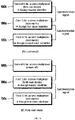
Fig. 7 is a flow chart for illustrating selection of operating modes of the G.hn access multiplexer (GAM) in the access network employing G.hn specification in accordance with an embodiment of the present invention andFig. 8 is a diagram for explaining clock synchronization among multiple G.hn access multiplexer (GAM) in the access network employing G.hn specification in accordance with an embodiment of the present invention. - Referring to
Fig. 7 , multipleG.hn access multiplexer Fig. 8 one G.hn access multiplexer (GAM) 100 as a master is connected with one G.hn access multiplexer (GAM) 100 as a slave but one G.hn access multiplexer (GAM) 100 as a master can be connected to multiple G.hn access multiplexer (GAM) 100 as slaves depending on an implementation and the G.hn access multiplexer (GAM) 100 operating as a slave can be additionally connected to a single or multiple of G.hn access multiplexer (GAM) operating as slaves. Depending on the embodiment of the present invention, the number of G.hn access multiplexer (GAM) communicating with each other may vary and, for example, seven G.hn access multiplexer (GAM) 100 devices can send and receive synchronization signal and operate as a master and a slave. - As shown in
Fig. 7 , at the initialization step of the G.hn access multiplexer (GAM) 100, the firstG.hn access multiplexer 100a decides first whether it can receive synchronization signal from the secondG.hn access multiplexer 100b (S210). If it receives synchronization signal, then the firstG.hn access multiplexer 100a enters lock mode with the secondG.hn access multiplexer 100b (S220) and operates according to the synchronization signal received from the secondG.hn access multiplexer 100b. In case it cannot receive synchronization signal from the secondG.hn access multiplexer 100b, the firstG.hn access multiplexer 100a enters free-run mode (S230) in which it operates according to the synchronization signal generated by the internal clock, and terminates the process. For example, when the secondG.hn access multiplexer 100b as shown in (A) ofFig. 8 selects operating mode by the process shown inFig. 7 , it enters free-run mode at the initialization step because it cannot receive synchronization signal from other G.hn access multiplexer (GAM) anyway. - While the first
G.hn access multiplexer 100a operates in lock mode, it decides whether it can receive synchronization signal from the secondG.hn access multiplexer 100b (S240). If the firstG.hn access multiplexer 100a operates as a slave to the secondG.hn access multiplexer 100b and as a master to the thirdG.hn access multiplexer 100c, then the firstG.hn access multiplexer 100a sends synchronization signal to the thirdG.hn access multiplexer 100c. In the example shown in (A) ofFig. 8 , for example, the firstG.hn access multiplexer 100a operating in lock mode with the secondG.hn access multiplexer 100b sends synchronization signal received from the secondG.hn access multiplexer 100b to the thirdG.hn access multiplexer 100c and the thirdG.hn access multiplexer 100c operates in lock mode with the secondG.hn access multiplexer 100b. - If the first
G.hn access multiplexer 100a decides that it cannot receive synchronization signal in the above step (S240) or if it cannot receive synchronization signal operating in lock mode, the firstG.hn access multiplexer 100a enters hold-over mode (S250) in which it sends synchronization signal generated by the internal clock of the thirdG.hn access multiplexer 100c. When the secondG.hn access multiplexer 100b shown in (A) ofFig. 8 is powered off, for example, the firstG.hn access multiplexer 100a enters hold-over mode since it cannot receive the synchronization signal from the secondG.hn access multiplexer 100b as shown in (B) ofFig. 8 and in the hold-over mode, it operates according to the synchronization signal generated based on the internal clock and sends the generated synchronization signal by itself to the slave, the thirdG.hn access multiplexer 100c. - If the first
G.hn access multiplexer 100a can receive synchronization signal in the above step (S240), it repeats the step (S220) and continuously operates in lock mode. - As such, operating in hold-over mode in case of failure of the master or the second
G.hn access multiplexer 100b minimizes the shift in the clock synchronization between the master (the secondG.hn access multiplexer 100b) and the slaves (the firstG.hn access multiplexer 100a or the thirdG.hn access multiplexer 100c) and maximizes the operation time for the entire network to work properly despite the malfunction of the G.hn access multiplexer (GAM) in the network. - According to the present invention as described before, the G.hn technology can be applied to the access network using the conventional copper cable or phone line to provide efficient data transmission with higher bandwidth to service subscribers and to reduce crosstalk in data transmission.
- The present invention has been described with reference to an embodiment shown in the figures, which is an exemplification only and the various embodiments are made possible by those who have ordinary knowledge in the area the present invention belongs to. Therefore, the technical scope of the present invention will be determined by the claims as follows.
Claims (6)
- An access multiplexer (100) comprising:a plurality of ports which are connected to access network terminals (200);a plurality of domain masters (120), each of which performs a master function on one of the ports of the access multiplexer (100);a switch (110) which is connected to the plurality of the domain masters (120);
wherein the ports are connected to the network terminals (200) via bundle cables (140), wherein crosstalk occurs within the bundle cables (140),
characterized in that the domain masters (120) are synchronized at a pre-determined frequency of less than 10 kHz to reduce the crosstalk occurring in the bundle cables (140), wherein the communication of the terminals (200) with the domain masters (120) is synchronized without sending or receiving a clock signal, wherein each domain master (120) is configured to accept communication from the corresponding terminal (200) using a protocol being able to communicate with the domain master (120) in at least one of a plurality of transmission opportunities, wherein one period of the frequency the domain masters (120) are synchronized with is divided into this plurality of transmission opportunities. - The access multiplexer of claim 1, wherein each of the plurality of domain masters (120) is configured to obtain a unique identifier, and connect with an end-point with the same identifier as the obtained identifier;
wherein the access multiplexer (100) is configured to be one of a first to third access multiplexers (100a, 100b, 100c) connected through upstream links,
wherein the first access multiplexer (100a) is configured toobtain the identifier from a first domain in case of not receiving a first synchronization signal from the second access multiplexer (100b) but transmitting a second synchronization signal to the third access multiplexer (100c),obtain the identifier from a second domain in case of receiving the first synchronization signal from the second access multiplexer (100b) and transmitting a third synchronization signal to the third access multiplexer (100c), andobtain the identifier from a third domain in case of receiving the first synchronization signal from the second access multiplexer (100b) and not transmitting the third synchronization signal to the third access multiplexer (100c),
wherein the first to third domains are configured not to be overlapped and the synchronization signals are signals at the pre-determined frequency of less than 10 kHz. - The access multiplexer of claim 1, wherein the access multiplexer (100) is configured to be one of a first to third access multiplexer (100a, 100b, 100c) connected through upstream links, wherein the first access multiplexer (100a) is configured to receive a first synchronization signal from the second access multiplexer (100b) and to transmit another synchronization signal to the domain master (120), and to further comprise a clock controller (130) configured to be operated in lock mode with the second access multiplexer (100b), and wherein the synchronization signals are signals at the pre-determined frequency of less than 10 kHz.
- An access network terminal (200) configured to:be connected to a port of an access multiplexer (100) via bundle cables (140), wherein a domain master (120) performs a master function on the port of the access multiplexer (100), and tobe one-to-one mapped with the domain master (120),
characterized in that the terminal (200) is configured to be synchronized at a pre-determined frequency of less than 10 kHz to reduce the crosstalk occurring within the bundle cables (140), wherein the communication of the terminal (200) with the domain master (120) is synchronized without sending or receiving a clock signal, wherein the terminal (200) is configured to communicate using a protocol being able to communicate with the domain master (120) in at least one of a plurality of transmission opportunities, wherein one period of the frequency the domain masters (120) are synchronized with is divided into this plurality of transmission opportunities. - An access network system configured to comprise:multiple access multiplexers (100) consisting of at least one master and at least one slave that are mutually connected with an uplink (10) and exchange synchronization signals, andaccess network terminals (200) configured to communicate at allocated time frames of the access multiplexers (100) based on the synchronization signals;
each of the respective access multiplexers (100) includes: a plurality of ports which are connected to the access network terminals (200), a plurality of domain masters (120), each of which performs a master function on one of the ports of the access multiplexer (100); a switch (110) which is connected to the domain masters (120);
wherein each of the access network terminals (200) is mapped one-to-one with one of the domain masters (120) and connected to the ports via bundle cables (140),
characterized in that the domain masters (120) are synchronized at a pre-determined frequency of less than 10 kHz to reduce crosstalk occurring within the bundle cables (140), wherein the communication of the terminals (200) with the domain masters (120) are synchronized without sending or receiving a clock signal, wherein each terminal (200) communicates using a protocol being able to communicate with the corresponding domain master (120) in at least one of a plurality of transmission opportunities, wherein one period of the frequency the domain masters (120) are synchronized with is divided into this plurality of transmission opportunities. - The access network system of claim 5, comprising at least three access multiplexers (100a, 100b, 100c), wherein the first access multiplexer (100a) is configured to receive a first synchronization signal from the second access multiplexer (100b) and to transmit another synchronization signal to the third multiplexer (110c), wherein all the three access multiplexers (100a, 100b, 100c) are configured to be operated in lock mode with the same synchronization signal, wherein the synchronization signals are signals at the pre-determined frequency of less than 10 kHz.
Applications Claiming Priority (6)
| Application Number | Priority Date | Filing Date | Title |
|---|---|---|---|
| KR1020140038628A KR101458380B1 (en) | 2014-04-01 | 2014-04-01 | An adaptive line rate control method based on g.hn technology |
| KR1020140038631A KR101403580B1 (en) | 2014-04-01 | 2014-04-01 | METHOD FOR APPLYING G.hn TO ACCESS NETWORK |
| KR1020140038629A KR101458389B1 (en) | 2014-04-01 | 2014-04-01 | DEVICE FOR APPLYING G.hn TO ACCESS NETWORK |
| KR1020140038632A KR101403590B1 (en) | 2014-04-01 | 2014-04-01 | METHOD FOR APPLYING G.hn TO ACCESS NETWORK |
| KR1020150032689A KR101690495B1 (en) | 2014-10-29 | 2015-03-09 | METHOD FOR SYNCHRONIZED COMMUNICATION OF ACCESS NETWORK BASED ON G.HN TECHNOLOGY AND G.hn ACCESS MULTIPLEXER, G.hn NETWORK TERMINAL, AND ACCESS NETWORK SYSTEM USING THE SAME |
| PCT/KR2015/002972 WO2015152569A1 (en) | 2014-04-01 | 2015-03-26 | Method for synchronization communication in access network having g.hn technology applied thereto, and access network line concentration instrument, access network terminal and access network system using same |
Publications (3)
| Publication Number | Publication Date |
|---|---|
| EP3128710A1 EP3128710A1 (en) | 2017-02-08 |
| EP3128710A4 EP3128710A4 (en) | 2018-02-28 |
| EP3128710B1 true EP3128710B1 (en) | 2021-09-08 |
Family
ID=57624248
Family Applications (2)
| Application Number | Title | Priority Date | Filing Date |
|---|---|---|---|
| EP15773094.6A Not-in-force EP3128709B1 (en) | 2014-04-01 | 2015-03-26 | Method for controlling line in access network having g.hn technology applied thereto, and access network line concentration instrument, access network terminal and access network system using same |
| EP15773139.9A Not-in-force EP3128710B1 (en) | 2014-04-01 | 2015-03-26 | Method for synchronization communication in access network having g.hn technology applied thereto, and access network line concentration instrument, access network terminal and access network system using same |
Family Applications Before (1)
| Application Number | Title | Priority Date | Filing Date |
|---|---|---|---|
| EP15773094.6A Not-in-force EP3128709B1 (en) | 2014-04-01 | 2015-03-26 | Method for controlling line in access network having g.hn technology applied thereto, and access network line concentration instrument, access network terminal and access network system using same |
Country Status (2)
| Country | Link |
|---|---|
| US (2) | US10666319B2 (en) |
| EP (2) | EP3128709B1 (en) |
Families Citing this family (4)
| Publication number | Priority date | Publication date | Assignee | Title |
|---|---|---|---|---|
| US11296748B2 (en) | 2016-05-11 | 2022-04-05 | Kt Corporation | Network management apparatus, customer premises equipment registration method therefor, and method for providing internet service to customer premises equipment |
| US11277198B2 (en) * | 2020-05-04 | 2022-03-15 | Hughes Network Systems, Llc | Monitoring operational status and detecting faults in a high throughput satellite system |
| US12301335B2 (en) | 2020-05-04 | 2025-05-13 | Hughes Network Systems, Llc | Monitoring operational status and detecting faults in a high throughput satellite system |
| WO2023081294A1 (en) * | 2021-11-03 | 2023-05-11 | Actelis Networks Inc. | Devices, systems and methods for transmitting data compliant with home networking standard over twisted pair cables |
Family Cites Families (23)
| Publication number | Priority date | Publication date | Assignee | Title |
|---|---|---|---|---|
| JP3529296B2 (en) * | 1999-04-16 | 2004-05-24 | 富士通株式会社 | Optical subscriber unit |
| US6697487B1 (en) * | 1999-05-17 | 2004-02-24 | Nortel Networks Limited | Power control data delivery consistency in copper plant |
| JP2001197043A (en) * | 2000-01-07 | 2001-07-19 | Fujitsu Ltd | Same sign continuous proof tester |
| US7580344B1 (en) * | 2002-05-17 | 2009-08-25 | Broadcom Corporation | Home phone line networking enhancements for multiple dwelling unit environments |
| US8543008B2 (en) * | 2005-03-01 | 2013-09-24 | Alexander I Soto | System and method for a subscriber powered network element |
| US9432433B2 (en) | 2006-06-09 | 2016-08-30 | Qualcomm Incorporated | Enhanced block-request streaming system using signaling or block creation |
| KR101222231B1 (en) | 2006-06-26 | 2013-01-15 | 주식회사 케이티 | Rate matching device, optical network device having the rate matching device and rate matching method in WDM-PON |
| KR100799587B1 (en) | 2006-11-17 | 2008-01-30 | 한국전자통신연구원 | Method and apparatus for dynamic bandwidth limitation in a switch |
| CN101309165B (en) * | 2007-05-14 | 2012-04-04 | 华为技术有限公司 | Control method, apparatus and equipment for information reporting |
| US7898983B2 (en) | 2007-07-05 | 2011-03-01 | Qualcomm Incorporated | Methods and apparatus supporting traffic signaling in peer to peer communications |
| KR20110056048A (en) | 2009-11-20 | 2011-05-26 | 주식회사 케이티 | Apparatus and method for dynamic bandwidth allocation using network quality values |
| JP5598243B2 (en) * | 2009-11-30 | 2014-10-01 | 株式会社Jvcケンウッド | FM detector, signal interpolation method, and program |
| JP5481679B2 (en) | 2010-03-16 | 2014-04-23 | 株式会社国際電気通信基礎技術研究所 | Receiver |
| WO2011151884A1 (en) * | 2010-05-31 | 2011-12-08 | 株式会社Jin-Magic | Communication apparatus and communication method |
| US9832107B2 (en) * | 2010-06-10 | 2017-11-28 | Infinera Corporation | Misconnection avoidance on networks |
| US8761201B2 (en) | 2010-10-22 | 2014-06-24 | Intel Corporation | Reducing the maximum latency of reserved streams |
| US9253808B2 (en) | 2011-07-10 | 2016-02-02 | Qualcomm Incorporated | Systems and methods for low-overhead wireless beacons having next full beacon indications |
| WO2013097122A1 (en) * | 2011-12-28 | 2013-07-04 | 华为技术有限公司 | Service channel bandwidth management method, relevant device and system in access network |
| US9504089B2 (en) | 2012-05-14 | 2016-11-22 | Broadcom Corporation | System and method for wireless station bridging |
| KR101234102B1 (en) | 2012-07-30 | 2013-02-20 | (주)엘프테크 | A circuit automatic switching apparatus and its operational method thereof |
| US9379882B2 (en) * | 2013-05-03 | 2016-06-28 | Broadcom Corporation | Synchronization and control using out-of-band channels in passive optical network-based systems |
| US9736055B2 (en) * | 2013-05-31 | 2017-08-15 | Metanoia Communications Inc. | Inter-medium bridging with inter-domain routing and multi-medium domain coordination |
| EP3076603B1 (en) * | 2013-11-25 | 2019-07-10 | KT Corporation | Interference mitigation apparatus and interference mitigation method for home network transmission line, and communication system using same |
-
2015
- 2015-03-26 US US15/301,384 patent/US10666319B2/en active Active
- 2015-03-26 EP EP15773094.6A patent/EP3128709B1/en not_active Not-in-force
- 2015-03-26 EP EP15773139.9A patent/EP3128710B1/en not_active Not-in-force
- 2015-03-26 US US15/301,386 patent/US10103778B2/en active Active
Also Published As
| Publication number | Publication date |
|---|---|
| EP3128709A1 (en) | 2017-02-08 |
| US10103778B2 (en) | 2018-10-16 |
| US20170026080A1 (en) | 2017-01-26 |
| EP3128710A4 (en) | 2018-02-28 |
| US10666319B2 (en) | 2020-05-26 |
| EP3128710A1 (en) | 2017-02-08 |
| US20170026079A1 (en) | 2017-01-26 |
| EP3128709A4 (en) | 2018-02-21 |
| EP3128709B1 (en) | 2021-09-08 |
Similar Documents
| Publication | Publication Date | Title |
|---|---|---|
| EP3672173B1 (en) | Communication method and device, and storage medium | |
| US8203983B2 (en) | Multi-domain network with centralized management | |
| CA2169151C (en) | Information communication network system, central information communication control device and information communication device used in the system, information sending method, andmodulation method | |
| JP5040695B2 (en) | PON station apparatus, PON uplink communication method, PON uplink communication program, and program recording medium | |
| US10666319B2 (en) | Method for synchronized communication in access network applied G.hn technology thereto, access network multiplexer, access network terminal and access network system using the same | |
| CN109039892B (en) | Service transmission method, network equipment and network system | |
| KR101403590B1 (en) | METHOD FOR APPLYING G.hn TO ACCESS NETWORK | |
| KR101690495B1 (en) | METHOD FOR SYNCHRONIZED COMMUNICATION OF ACCESS NETWORK BASED ON G.HN TECHNOLOGY AND G.hn ACCESS MULTIPLEXER, G.hn NETWORK TERMINAL, AND ACCESS NETWORK SYSTEM USING THE SAME | |
| CN105765913B (en) | Interference mitigation device for home network transmission line, interference mitigation method, and communication system | |
| KR101474520B1 (en) | Device for mitigating interference home network transmission line, method for mitigating interference and communication system using the same | |
| US20150229432A1 (en) | Full-duplex ethernet communications over coaxial links using time-division duplexing | |
| EP3091675B1 (en) | Apparatus and method for accessing network | |
| US10541829B2 (en) | Network devices for scalable point to multipoint networks | |
| Dominiak et al. | The application of commercial power line communications technology for avionics systems | |
| USRE39116E1 (en) | Network link detection and generation | |
| US20110235657A1 (en) | Multimode Apparatus and Method | |
| US7656900B2 (en) | Methods and systems for adaptive communication | |
| EP3457636B1 (en) | Network management device, customer premises equipment registration method therefor, and method for providing internet service to customer premises equipment | |
| EP4528522A1 (en) | Network device, device communication method, and communication system | |
| CN105391666A (en) | Multi-service bus transmission system and transmission method based on FSK modem | |
| US20090132727A1 (en) | System for connecting different components, network forwarding component and independent application component | |
| WO2015152569A1 (en) | Method for synchronization communication in access network having g.hn technology applied thereto, and access network line concentration instrument, access network terminal and access network system using same | |
| US10193670B2 (en) | Methods and systems for communication | |
| WO2001063788A2 (en) | A power line communications system | |
| US20140064157A1 (en) | Method and apparatus for providing bidirectional communication between segments of a home network |
Legal Events
| Date | Code | Title | Description |
|---|---|---|---|
| STAA | Information on the status of an ep patent application or granted ep patent |
Free format text: STATUS: THE INTERNATIONAL PUBLICATION HAS BEEN MADE |
|
| PUAI | Public reference made under article 153(3) epc to a published international application that has entered the european phase |
Free format text: ORIGINAL CODE: 0009012 |
|
| STAA | Information on the status of an ep patent application or granted ep patent |
Free format text: STATUS: REQUEST FOR EXAMINATION WAS MADE |
|
| 17P | Request for examination filed |
Effective date: 20160927 |
|
| AK | Designated contracting states |
Kind code of ref document: A1 Designated state(s): AL AT BE BG CH CY CZ DE DK EE ES FI FR GB GR HR HU IE IS IT LI LT LU LV MC MK MT NL NO PL PT RO RS SE SI SK SM TR |
|
| AX | Request for extension of the european patent |
Extension state: BA ME |
|
| DAV | Request for validation of the european patent (deleted) | ||
| DAX | Request for extension of the european patent (deleted) | ||
| RIC1 | Information provided on ipc code assigned before grant |
Ipc: H04L 29/02 20060101AFI20171002BHEP Ipc: H04M 11/06 20060101ALI20171002BHEP Ipc: H04L 7/00 20060101ALI20171002BHEP Ipc: H04L 29/12 20060101ALI20171002BHEP |
|
| A4 | Supplementary search report drawn up and despatched |
Effective date: 20180125 |
|
| RIC1 | Information provided on ipc code assigned before grant |
Ipc: H04L 29/02 20060101AFI20180119BHEP Ipc: H04L 29/12 20060101ALI20180119BHEP Ipc: H04L 7/00 20060101ALI20180119BHEP Ipc: H04M 11/06 20060101ALI20180119BHEP |
|
| STAA | Information on the status of an ep patent application or granted ep patent |
Free format text: STATUS: EXAMINATION IS IN PROGRESS |
|
| 17Q | First examination report despatched |
Effective date: 20181130 |
|
| GRAP | Despatch of communication of intention to grant a patent |
Free format text: ORIGINAL CODE: EPIDOSNIGR1 |
|
| STAA | Information on the status of an ep patent application or granted ep patent |
Free format text: STATUS: GRANT OF PATENT IS INTENDED |
|
| RIC1 | Information provided on ipc code assigned before grant |
Ipc: H04L 5/00 20060101ALI20210311BHEP Ipc: H04L 12/801 20130101ALI20210311BHEP Ipc: H04L 12/64 20060101ALI20210311BHEP Ipc: H04L 12/28 20060101ALI20210311BHEP Ipc: H04B 3/54 20060101ALI20210311BHEP Ipc: H04B 3/32 20060101ALI20210311BHEP Ipc: H04L 12/24 20060101ALI20210311BHEP Ipc: H04L 29/12 20060101ALI20210311BHEP Ipc: H04L 7/00 20060101ALI20210311BHEP Ipc: H04M 11/06 20060101ALI20210311BHEP Ipc: H04L 29/02 20060101AFI20210311BHEP |
|
| INTG | Intention to grant announced |
Effective date: 20210406 |
|
| GRAS | Grant fee paid |
Free format text: ORIGINAL CODE: EPIDOSNIGR3 |
|
| GRAA | (expected) grant |
Free format text: ORIGINAL CODE: 0009210 |
|
| STAA | Information on the status of an ep patent application or granted ep patent |
Free format text: STATUS: THE PATENT HAS BEEN GRANTED |
|
| AK | Designated contracting states |
Kind code of ref document: B1 Designated state(s): AL AT BE BG CH CY CZ DE DK EE ES FI FR GB GR HR HU IE IS IT LI LT LU LV MC MK MT NL NO PL PT RO RS SE SI SK SM TR |
|
| REG | Reference to a national code |
Ref country code: GB Ref legal event code: FG4D |
|
| REG | Reference to a national code |
Ref country code: CH Ref legal event code: EP Ref country code: AT Ref legal event code: REF Ref document number: 1429585 Country of ref document: AT Kind code of ref document: T Effective date: 20210915 |
|
| REG | Reference to a national code |
Ref country code: DE Ref legal event code: R096 Ref document number: 602015073120 Country of ref document: DE |
|
| REG | Reference to a national code |
Ref country code: IE Ref legal event code: FG4D |
|
| REG | Reference to a national code |
Ref country code: DE Ref legal event code: R079 Ref document number: 602015073120 Country of ref document: DE Free format text: PREVIOUS MAIN CLASS: H04L0029020000 Ipc: H04L0065000000 |
|
| REG | Reference to a national code |
Ref country code: LT Ref legal event code: MG9D |
|
| REG | Reference to a national code |
Ref country code: NL Ref legal event code: MP Effective date: 20210908 |
|
| PG25 | Lapsed in a contracting state [announced via postgrant information from national office to epo] |
Ref country code: ES Free format text: LAPSE BECAUSE OF FAILURE TO SUBMIT A TRANSLATION OF THE DESCRIPTION OR TO PAY THE FEE WITHIN THE PRESCRIBED TIME-LIMIT Effective date: 20210908 Ref country code: FI Free format text: LAPSE BECAUSE OF FAILURE TO SUBMIT A TRANSLATION OF THE DESCRIPTION OR TO PAY THE FEE WITHIN THE PRESCRIBED TIME-LIMIT Effective date: 20210908 Ref country code: NO Free format text: LAPSE BECAUSE OF FAILURE TO SUBMIT A TRANSLATION OF THE DESCRIPTION OR TO PAY THE FEE WITHIN THE PRESCRIBED TIME-LIMIT Effective date: 20211208 Ref country code: LT Free format text: LAPSE BECAUSE OF FAILURE TO SUBMIT A TRANSLATION OF THE DESCRIPTION OR TO PAY THE FEE WITHIN THE PRESCRIBED TIME-LIMIT Effective date: 20210908 Ref country code: BG Free format text: LAPSE BECAUSE OF FAILURE TO SUBMIT A TRANSLATION OF THE DESCRIPTION OR TO PAY THE FEE WITHIN THE PRESCRIBED TIME-LIMIT Effective date: 20211208 Ref country code: SE Free format text: LAPSE BECAUSE OF FAILURE TO SUBMIT A TRANSLATION OF THE DESCRIPTION OR TO PAY THE FEE WITHIN THE PRESCRIBED TIME-LIMIT Effective date: 20210908 Ref country code: RS Free format text: LAPSE BECAUSE OF FAILURE TO SUBMIT A TRANSLATION OF THE DESCRIPTION OR TO PAY THE FEE WITHIN THE PRESCRIBED TIME-LIMIT Effective date: 20210908 Ref country code: HR Free format text: LAPSE BECAUSE OF FAILURE TO SUBMIT A TRANSLATION OF THE DESCRIPTION OR TO PAY THE FEE WITHIN THE PRESCRIBED TIME-LIMIT Effective date: 20210908 |
|
| REG | Reference to a national code |
Ref country code: AT Ref legal event code: MK05 Ref document number: 1429585 Country of ref document: AT Kind code of ref document: T Effective date: 20210908 |
|
| PG25 | Lapsed in a contracting state [announced via postgrant information from national office to epo] |
Ref country code: LV Free format text: LAPSE BECAUSE OF FAILURE TO SUBMIT A TRANSLATION OF THE DESCRIPTION OR TO PAY THE FEE WITHIN THE PRESCRIBED TIME-LIMIT Effective date: 20210908 Ref country code: GR Free format text: LAPSE BECAUSE OF FAILURE TO SUBMIT A TRANSLATION OF THE DESCRIPTION OR TO PAY THE FEE WITHIN THE PRESCRIBED TIME-LIMIT Effective date: 20211209 |
|
| PG25 | Lapsed in a contracting state [announced via postgrant information from national office to epo] |
Ref country code: AT Free format text: LAPSE BECAUSE OF FAILURE TO SUBMIT A TRANSLATION OF THE DESCRIPTION OR TO PAY THE FEE WITHIN THE PRESCRIBED TIME-LIMIT Effective date: 20210908 |
|
| PG25 | Lapsed in a contracting state [announced via postgrant information from national office to epo] |
Ref country code: IS Free format text: LAPSE BECAUSE OF FAILURE TO SUBMIT A TRANSLATION OF THE DESCRIPTION OR TO PAY THE FEE WITHIN THE PRESCRIBED TIME-LIMIT Effective date: 20220108 Ref country code: SM Free format text: LAPSE BECAUSE OF FAILURE TO SUBMIT A TRANSLATION OF THE DESCRIPTION OR TO PAY THE FEE WITHIN THE PRESCRIBED TIME-LIMIT Effective date: 20210908 Ref country code: SK Free format text: LAPSE BECAUSE OF FAILURE TO SUBMIT A TRANSLATION OF THE DESCRIPTION OR TO PAY THE FEE WITHIN THE PRESCRIBED TIME-LIMIT Effective date: 20210908 Ref country code: RO Free format text: LAPSE BECAUSE OF FAILURE TO SUBMIT A TRANSLATION OF THE DESCRIPTION OR TO PAY THE FEE WITHIN THE PRESCRIBED TIME-LIMIT Effective date: 20210908 Ref country code: PT Free format text: LAPSE BECAUSE OF FAILURE TO SUBMIT A TRANSLATION OF THE DESCRIPTION OR TO PAY THE FEE WITHIN THE PRESCRIBED TIME-LIMIT Effective date: 20220110 Ref country code: PL Free format text: LAPSE BECAUSE OF FAILURE TO SUBMIT A TRANSLATION OF THE DESCRIPTION OR TO PAY THE FEE WITHIN THE PRESCRIBED TIME-LIMIT Effective date: 20210908 Ref country code: NL Free format text: LAPSE BECAUSE OF FAILURE TO SUBMIT A TRANSLATION OF THE DESCRIPTION OR TO PAY THE FEE WITHIN THE PRESCRIBED TIME-LIMIT Effective date: 20210908 Ref country code: EE Free format text: LAPSE BECAUSE OF FAILURE TO SUBMIT A TRANSLATION OF THE DESCRIPTION OR TO PAY THE FEE WITHIN THE PRESCRIBED TIME-LIMIT Effective date: 20210908 Ref country code: CZ Free format text: LAPSE BECAUSE OF FAILURE TO SUBMIT A TRANSLATION OF THE DESCRIPTION OR TO PAY THE FEE WITHIN THE PRESCRIBED TIME-LIMIT Effective date: 20210908 Ref country code: AL Free format text: LAPSE BECAUSE OF FAILURE TO SUBMIT A TRANSLATION OF THE DESCRIPTION OR TO PAY THE FEE WITHIN THE PRESCRIBED TIME-LIMIT Effective date: 20210908 |
|
| REG | Reference to a national code |
Ref country code: DE Ref legal event code: R097 Ref document number: 602015073120 Country of ref document: DE |
|
| PLBE | No opposition filed within time limit |
Free format text: ORIGINAL CODE: 0009261 |
|
| STAA | Information on the status of an ep patent application or granted ep patent |
Free format text: STATUS: NO OPPOSITION FILED WITHIN TIME LIMIT |
|
| PG25 | Lapsed in a contracting state [announced via postgrant information from national office to epo] |
Ref country code: DK Free format text: LAPSE BECAUSE OF FAILURE TO SUBMIT A TRANSLATION OF THE DESCRIPTION OR TO PAY THE FEE WITHIN THE PRESCRIBED TIME-LIMIT Effective date: 20210908 |
|
| 26N | No opposition filed |
Effective date: 20220609 |
|
| PG25 | Lapsed in a contracting state [announced via postgrant information from national office to epo] |
Ref country code: SI Free format text: LAPSE BECAUSE OF FAILURE TO SUBMIT A TRANSLATION OF THE DESCRIPTION OR TO PAY THE FEE WITHIN THE PRESCRIBED TIME-LIMIT Effective date: 20210908 |
|
| PG25 | Lapsed in a contracting state [announced via postgrant information from national office to epo] |
Ref country code: MC Free format text: LAPSE BECAUSE OF FAILURE TO SUBMIT A TRANSLATION OF THE DESCRIPTION OR TO PAY THE FEE WITHIN THE PRESCRIBED TIME-LIMIT Effective date: 20210908 |
|
| REG | Reference to a national code |
Ref country code: CH Ref legal event code: PL |
|
| GBPC | Gb: european patent ceased through non-payment of renewal fee |
Effective date: 20220326 |
|
| REG | Reference to a national code |
Ref country code: BE Ref legal event code: MM Effective date: 20220331 |
|
| PG25 | Lapsed in a contracting state [announced via postgrant information from national office to epo] |
Ref country code: LU Free format text: LAPSE BECAUSE OF NON-PAYMENT OF DUE FEES Effective date: 20220326 Ref country code: LI Free format text: LAPSE BECAUSE OF NON-PAYMENT OF DUE FEES Effective date: 20220331 Ref country code: IT Free format text: LAPSE BECAUSE OF FAILURE TO SUBMIT A TRANSLATION OF THE DESCRIPTION OR TO PAY THE FEE WITHIN THE PRESCRIBED TIME-LIMIT Effective date: 20210908 Ref country code: IE Free format text: LAPSE BECAUSE OF NON-PAYMENT OF DUE FEES Effective date: 20220326 Ref country code: GB Free format text: LAPSE BECAUSE OF NON-PAYMENT OF DUE FEES Effective date: 20220326 Ref country code: FR Free format text: LAPSE BECAUSE OF NON-PAYMENT OF DUE FEES Effective date: 20220331 Ref country code: CH Free format text: LAPSE BECAUSE OF NON-PAYMENT OF DUE FEES Effective date: 20220331 |
|
| PG25 | Lapsed in a contracting state [announced via postgrant information from national office to epo] |
Ref country code: BE Free format text: LAPSE BECAUSE OF NON-PAYMENT OF DUE FEES Effective date: 20220331 |
|
| P01 | Opt-out of the competence of the unified patent court (upc) registered |
Effective date: 20230526 |
|
| PG25 | Lapsed in a contracting state [announced via postgrant information from national office to epo] |
Ref country code: HU Free format text: LAPSE BECAUSE OF FAILURE TO SUBMIT A TRANSLATION OF THE DESCRIPTION OR TO PAY THE FEE WITHIN THE PRESCRIBED TIME-LIMIT; INVALID AB INITIO Effective date: 20150326 |
|
| PG25 | Lapsed in a contracting state [announced via postgrant information from national office to epo] |
Ref country code: MK Free format text: LAPSE BECAUSE OF FAILURE TO SUBMIT A TRANSLATION OF THE DESCRIPTION OR TO PAY THE FEE WITHIN THE PRESCRIBED TIME-LIMIT Effective date: 20210908 Ref country code: CY Free format text: LAPSE BECAUSE OF FAILURE TO SUBMIT A TRANSLATION OF THE DESCRIPTION OR TO PAY THE FEE WITHIN THE PRESCRIBED TIME-LIMIT Effective date: 20210908 |
|
| PGFP | Annual fee paid to national office [announced via postgrant information from national office to epo] |
Ref country code: DE Payment date: 20240327 Year of fee payment: 10 |
|
| PG25 | Lapsed in a contracting state [announced via postgrant information from national office to epo] |
Ref country code: MT Free format text: LAPSE BECAUSE OF FAILURE TO SUBMIT A TRANSLATION OF THE DESCRIPTION OR TO PAY THE FEE WITHIN THE PRESCRIBED TIME-LIMIT Effective date: 20210908 |
|
| REG | Reference to a national code |
Ref country code: DE Ref legal event code: R119 Ref document number: 602015073120 Country of ref document: DE |
|
| PG25 | Lapsed in a contracting state [announced via postgrant information from national office to epo] |
Ref country code: TR Free format text: LAPSE BECAUSE OF FAILURE TO SUBMIT A TRANSLATION OF THE DESCRIPTION OR TO PAY THE FEE WITHIN THE PRESCRIBED TIME-LIMIT Effective date: 20210908 |
|
| PG25 | Lapsed in a contracting state [announced via postgrant information from national office to epo] |
Ref country code: DE Free format text: LAPSE BECAUSE OF NON-PAYMENT OF DUE FEES Effective date: 20251001 |