US11296748B2 - Network management apparatus, customer premises equipment registration method therefor, and method for providing internet service to customer premises equipment - Google Patents
Network management apparatus, customer premises equipment registration method therefor, and method for providing internet service to customer premises equipment Download PDFInfo
- Publication number
- US11296748B2 US11296748B2 US16/300,096 US201716300096A US11296748B2 US 11296748 B2 US11296748 B2 US 11296748B2 US 201716300096 A US201716300096 A US 201716300096A US 11296748 B2 US11296748 B2 US 11296748B2
- Authority
- US
- United States
- Prior art keywords
- signal
- network management
- customer premises
- premises equipment
- registration response
- Prior art date
- Legal status (The legal status is an assumption and is not a legal conclusion. Google has not performed a legal analysis and makes no representation as to the accuracy of the status listed.)
- Active, expires
Links
Images


Classifications
-
- H—ELECTRICITY
- H04—ELECTRIC COMMUNICATION TECHNIQUE
- H04B—TRANSMISSION
- H04B3/00—Line transmission systems
- H04B3/02—Details
- H04B3/32—Reducing cross-talk, e.g. by compensating
-
- H—ELECTRICITY
- H04—ELECTRIC COMMUNICATION TECHNIQUE
- H04J—MULTIPLEX COMMUNICATION
- H04J1/00—Frequency-division multiplex systems
- H04J1/02—Details
- H04J1/12—Arrangements for reducing cross-talk between channels
-
- H—ELECTRICITY
- H04—ELECTRIC COMMUNICATION TECHNIQUE
- H04J—MULTIPLEX COMMUNICATION
- H04J1/00—Frequency-division multiplex systems
- H04J1/02—Details
- H04J1/16—Monitoring arrangements
-
- H—ELECTRICITY
- H04—ELECTRIC COMMUNICATION TECHNIQUE
- H04L—TRANSMISSION OF DIGITAL INFORMATION, e.g. TELEGRAPHIC COMMUNICATION
- H04L12/00—Data switching networks
- H04L12/28—Data switching networks characterised by path configuration, e.g. LAN [Local Area Networks] or WAN [Wide Area Networks]
-
- H—ELECTRICITY
- H04—ELECTRIC COMMUNICATION TECHNIQUE
- H04L—TRANSMISSION OF DIGITAL INFORMATION, e.g. TELEGRAPHIC COMMUNICATION
- H04L25/00—Baseband systems
- H04L25/02—Details ; arrangements for supplying electrical power along data transmission lines
-
- H—ELECTRICITY
- H04—ELECTRIC COMMUNICATION TECHNIQUE
- H04L—TRANSMISSION OF DIGITAL INFORMATION, e.g. TELEGRAPHIC COMMUNICATION
- H04L25/00—Baseband systems
- H04L25/02—Details ; arrangements for supplying electrical power along data transmission lines
- H04L25/08—Modifications for reducing interference; Modifications for reducing effects due to line faults ; Receiver end arrangements for detecting or overcoming line faults
-
- H—ELECTRICITY
- H04—ELECTRIC COMMUNICATION TECHNIQUE
- H04L—TRANSMISSION OF DIGITAL INFORMATION, e.g. TELEGRAPHIC COMMUNICATION
- H04L27/00—Modulated-carrier systems
- H04L27/26—Systems using multi-frequency codes
-
- H—ELECTRICITY
- H04—ELECTRIC COMMUNICATION TECHNIQUE
- H04L—TRANSMISSION OF DIGITAL INFORMATION, e.g. TELEGRAPHIC COMMUNICATION
- H04L41/00—Arrangements for maintenance, administration or management of data switching networks, e.g. of packet switching networks
- H04L41/08—Configuration management of networks or network elements
- H04L41/0803—Configuration setting
- H04L41/0806—Configuration setting for initial configuration or provisioning, e.g. plug-and-play
-
- H—ELECTRICITY
- H04—ELECTRIC COMMUNICATION TECHNIQUE
- H04L—TRANSMISSION OF DIGITAL INFORMATION, e.g. TELEGRAPHIC COMMUNICATION
- H04L7/00—Arrangements for synchronising receiver with transmitter
-
- H—ELECTRICITY
- H04—ELECTRIC COMMUNICATION TECHNIQUE
- H04W—WIRELESS COMMUNICATION NETWORKS
- H04W8/00—Network data management
- H04W8/18—Processing of user or subscriber data, e.g. subscribed services, user preferences or user profiles; Transfer of user or subscriber data
Definitions
- the present invention relates to a network management apparatus, a customer premise equipment registration method thereof, and a method for providing Internet services to the customer premise equipment.
- a network device In the case of dense buildings such as apartments, homes,—townhouses, warehouse, etc., a network device is connected to a plurality of subscriber terminals through a main distribution frame (MDF) of the building to which subscriber lines are connected.
- MDF main distribution frame
- Various Internet services are provided to the subscribers according to specific subscribed Internet products and the type of subscriber lines.
- a link may not be established in the directly connected line in the bundled access network.
- An interference signal (crosstalk) between adjacent lines causes the misconnection to an adjacent port or to an adjacent modem.
- adjacent signals may be distinguished by for example Seed ID and MAC.
- Seed ID For example Seed ID
- MAC Media Access Control
- the present invention provides a method for Giga Internet service using bundled copper line cables between subscriber terminals and a concentrator in a building, and providing an optimal communication service to subscribers by eliminating errors in a link establishment and connecting the best performing modem in a Giga Internet service.
- the present invention also provides a network management apparatus for mitigating interference in premises communication lines, and a method for providing Internet services to customer premises equipment using the same.
- An exemplary embodiment provides a method for registering customer premises equipment to provide an Internet service to the customer premises equipment by a network management apparatus of an access network structure, wherein the network management apparatus and the customer premises equipment are connected through a bundle cable including a plurality of lines in the access network structure.
- the method may include transmitting a registration signal toward a customer premises equipment, receiving registration response signals transmitted from the customer premises equipment through the plurality of lines, analyzing the registration response signals introduced from the plurality of lines and distinguishing a direct signal transmitted through a properly connected line and interference signal from the registration response signals, and establishing a link with the customer premises equipment connected to the properly connected line.
- the interference signal is introduced through adjacent line of the properly connected line among the plurality of lines.
- an embodiment of the present invention may measure a signal strength of the registration response signal introduced from each line, select one or more lines having a large signal strength, and determine whether the registration response signal introduced from each of the selected lines is the direct signal or the interference signal by analyzing a channel frequency response of each of the selected lines.
- the selecting one or more lines may include selecting one or more lines having the larger signal strength than a threshold or selecting a plurality of lines high ranked as the the signal strength.
- To determine whether the registration response signal is the direct signal or the interference signal may include calculating a characteristic curve slope in a low frequency band of the channel frequency response, and determining the registration response signal to the direct signal when the characteristic curve slope is negative, and determining the registration response signal to the interference signal when the characteristic curve slope is positive.
- the characteristic curve slope may be calculated based on variation amounts from a channel frequency response value at a first frequency to a channel frequency response value at a second frequency.
- the first frequency may be the lowest frequency in the low frequency band
- the second frequency may be the maximum frequency in the low frequency band.
- To determine whether the registration response signal is the direct signal or the interference signal may include calculating characteristic curve slopes in a plurality of low frequency band of the channel frequency response, and determining the registration response signal to the direct signal when a ratio of the negative characteristic curve slopes is high, and determining the registration response signal to the interference signal when a ratio of negative characteristic curve slopes is low.
- the receiving registration response may receive a plurality of registration response signals transmitted from the customer premises equipment. To distinguish the direct signal an average value of the plurality of registration response signals may be used.
- the network management apparatus may include a transceiver that transmits and receives registration signals or registration response signals with customer premises equipment.
- a memory that stores a program for registering the customer premises equipment in the network management apparatus.
- a processor that executes an operation implemented by the program in conjunction with the transceiver and the memory.
- the program includes instructions for transmitting the registration signal toward a customer premises equipment, receiving registration response signals transmitted from the customer premises equipment through the plurality of lines, analyzing the registration response signals introduced from the plurality of lines and distinguishing a direct signal transmitted through a properly connected line and interference signal from the registration response signals, and establishing a link with the customer premises equipment connected to the properly connected line.
- the interference signal is introduced through adjacent line of the properly connected line among the plurality of lines.
- the program may include instructions for measuring a signal strength of the registration response signal introduced from each line, selecting one or more lines having a large signal strength, and determining whether the registration response signal introduced from each of the selected lines is the direct signal or the interference signal by analyzing a channel frequency response of each of the selected lines.
- the program may include instructions for selecting one or more lines having the larger signal strength than a threshold or selecting a plurality of lines high ranked as the the signal strength.
- the program may include instructions for calculating a characteristic curve slope in a low frequency band of the channel frequency response, and determining the registration response signal to the direct signal when the characteristic curve slope is negative and determining the registration response signal to the interference signal when the characteristic curve slope is positive.
- the program may include instructions for calculating the characteristic curve slope based on variation amounts from a channel frequency response value at a first frequency to a channel frequency response value at a second frequency.
- the first frequency may the lowest frequency in the low frequency band, and the second frequency may the maximum frequency in the low frequency band.
- the program may include instructions for calculating characteristic curve slopes in a plurality of low frequency band of the channel frequency response, and determining the registration response signal to the direct signal when a ratio of the negative characteristic curve slopes is high, and determining the registration response signal to the interference signal when a ratio of negative characteristic curve slopes is low.
- the transceiver may receive a plurality of registration response signals transmitted from the customer premises equipment.
- the program may include instructions for distinguishing the direct signal and the interference signal by using an average value of the plurality of registration response signals.
- the network management apparatus includes a channel estimator analyzing response signals applied through a plurality of lines from the customer premises equipment and distinguishing a direct signal transmitted through a properly connected line among the plurality of lines and an interference signal introduced through an adjacent line among the plurality of lines.
- a controller establishing a link with the customer premises equipment connected through the properly connected line and controlling data transmission and reception with the customer premises equipment: and a pairing unit establishing the link with the customer premises equipment by transmitting and receiving a signal having a unique frequency.
- the channel estimator may measure a signal strength of the registration response signal introduced from each line, select one or more lines having a large signal strength, and determine whether the registration response signal introduced from each of the selected lines is the direct signal or the interference signal by analyzing a channel frequency response of each of the selected lines.
- the channel estimator may calculate a characteristic curve slope in a low frequency band of the channel frequency response, and determine the registration response signal to the direct signal when the characteristic curve slope is negative, and determine the registration response signal to the interference signal when the characteristic curve slope is positive.
- the channel estimator may calculate the characteristic curve slope based on variation amounts from a channel frequency response value at a first frequency to a channel frequency response value at a second frequency.
- the first frequency may be the lowest frequency in the low frequency band
- the second frequency may be the maximum frequency in the low frequency band.
- the channel estimator may calculate characteristic curve slopes in a plurality of low frequency band of the channel frequency response, and determine the registration response signal to the direct signal when a ratio of the negative characteristic curve slopes is high, and determining the registration response signal to the interference signal when a ratio of negative characteristic curve slopes is low.
- Yet another embodiment provides a method for providing an Internet service to customer premises equipment by a network management apparatus of an access network structure, wherein one or more network management apparatus and one or more customer premises equipment are connected to each other through a bundle cable in the access network structure.
- the method includes pairing with a customer premises equipment by transmitting and receiving a pairing pulse signal which is pre-assigned to each of the ports, transmitting, to a server, a seed ID requesting message for changing or newly registering a domain ID, and establishing a link with the customer premises equipment using the seed ID received from the server.
- the access network structure may include a first network management apparatus and a second network management apparatus connected to the common bundle cable.
- the first network management apparatus may transmit the timing information to the second network management apparatus.
- the second network management apparatus may synchronize with the first network management apparatuses using the timing information for operation.
- the timing information may be transmitted from the first network management apparatus to the second network management apparatus through one or more of a UTP cable, an optical fiber cable, and a coaxial cable.
- Yet another embodiment provides a method for providing an Internet service to customer premises equipment in an access network structure in which one or more network management apparatuses and one or more customer premises equipment are connected to each other through the same bundle cable.
- the method includes by the network management apparatus, pairing with a customer premises equipment by transmitting and receiving a pairing pulse signal which is pre-assigned to each of the ports; by the network management apparatus, transmitting, to a server, a seed ID requesting message for changing or newly registering a domain ID; by the server, retrieving information on the network management apparatus and the customer premises equipment paired with the network management apparatus, generating a seed ID for establishing the link between the network management apparatus and the customer premises equipment, and transmitting the seed ID to the network management apparatus; and by the network management apparatus, establishing the link with the customer premises equipment using the seed ID received from the server.
- the method may further include, by the server, transmitting the timing information to the network management apparatus; and by the network management apparatus, synchronizing an internal clock with the server by using the timing information and being operated.
- the server may used at least one synchronization method of IEEE 1588, NTP (Network Time Protocol) and OFDM preamble (Orthogonal Frequency Division Multiplexing preamble) for transmitting the timing information to the network management apparatuses.
- IEEE 1588 Network Time Protocol
- OFDM preamble Orthogonal Frequency Division Multiplexing preamble
- the access network structure may include a plurality of network management apparatuses.
- the method may further include first network management apparatuses, which are one or more of the plurality of network management apparatuses transmitting the timing information to a second network management apparatus, which is a peripheral network management apparatus connected through the same bundle cable.
- the method may further include the second network management apparatus synchronizing with the first network management apparatuses using the timing information and being operated.
- the timing information may be transmitted from the first network management apparatus to the second network management apparatus through one or more of a UTP cable, an optical fiber cable, and a coaxial cable.
- Yet another embodiment provides a network management apparatus that manages a line connected to a premises of an Internet service subscriber includes a transceiver transmitting and receiving a signal with customer premises equipment, a memory in which a program for providing an Internet service to the customer premises equipment is stored, and a processor that executes an operation implemented by the program in conjunction with the transceiver and the memory.
- the program includes instructions for pairing with the customer premises equipment by transmitting and receiving a pre-assigned pulse signal, transmitting a seed ID requesting message for changing a domain ID to a server, and establishing a link with the customer premises equipment by using the seed ID received from the server.
- the program may further include instructions for receiving timing information from the server, and synchronizing an internal clock with the server by using the timing information and operating the network management apparatuses.
- the program may further include instructions for transmitting the timing information to peripheral network management apparatuses connected through the same bundle cable.
- FIG. 1 is a diagram illustrating a copper line-based access network structure according to an exemplary embodiment.
- FIG. 2 is a diagram illustrating a network management apparatus according to an exemplary embodiment.
- FIG. 3 is a diagram illustrating frequency domain response characteristics of a direct signal transmitted from a properly connected line and an interference signal introduced from an adjacent line of the properly connected line.
- FIG. 4 is a diagram illustrating a method for determining a slope of a channel frequency response curve in a frequency band by a network management apparatus according to an exemplary embodiment.
- FIG. 5 is a flowchart illustrating a method for registering a customer premises equipment to provide an Internet service by a network management apparatus according to an exemplary embodiment.
- FIG. 6 is a diagram illustrating another copper line-based network structure according to another exemplary embodiment.
- FIG. 7 is a diagram illustrating a network management apparatus according to another exemplary embodiment.
- FIG. 8 is a flowchart illustrating a method for providing an Internet service to a customer premises equipment by a network management apparatus according to another exemplary embodiment.
- the word “comprise” and variations such as “comprises” or “comprising”, will be understood to imply the inclusion of stated elements but not the exclusion of any other elements.
- the term such as “part”, “module”, or the like means a unit of processing at least one function or operation, and be implemented by hardware or software or be implemented by a combination of hardware and software.
- the “network device” refers to a device installed by an Internet service provider to provide an Internet service to a subscriber.
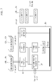
- FIG. 1 is a diagram illustrating a copper line-based access network structure according to an exemplary embodiment.
- a network management system includes a server 10 , at least one network management apparatus 100 , and customer premises equipment 200 ( 200 a , 200 b , 200 c , 200 d , 200 e and 200 f ).
- the server 10 connects with at least one service provider and connects with the network management apparatus 100 through optical cables, fiber to the x (FTTx), or an Internet network.
- the server 10 manages an Internet service policy and a network of several customer premise equipment 200 installed at the premises of Internet subscribers.
- the network management apparatus 100 is a master equipment (ME).
- the network management apparatus 100 and customer premises equipment (CPEs), which are subscriber modems, are connected through a bundle cable C.
- the network management apparatus 100 is connected to a plurality of modems through copper lines to configure a Giga Internet network.
- the network management apparatus 100 may be installed in a communications room or a copper terminal box of a building.
- the network management apparatus 100 may be referred to as a concentrator.
- the network management apparatus 100 pairs with each of the customer premises equipment 200 .
- the network management apparatus 100 connects with the customer premises equipment 200 through at least one transmission line.
- the network management apparatus 100 determines the strongest (best) signal among signals from the customer premises equipment 200 , and establishes a link with the customer premises equipment 200 on the correct line.
- FIG. 2 is a diagram illustrating a network management apparatus according to an exemplary embodiment.
- the network management apparatus 100 includes a pairing unit 110 , a channel estimator 120 , and a controller 130 .
- the pairing unit 110 pairs with the customer premises equipment 200 using a signal having a unique frequency.
- the pairing unit 110 establishes a link with the customer premises equipment 200 by transmitting and receiving a pairing pulse signal designated to each of the ports of the network management apparatus 100 .
- the pairing pulse signal received from the customer premises equipment 200 may include information on the customer premises equipment 200 such as an MAC address.
- the channel estimator 120 transmits a registration signal/registration message, which is a type of a test signal transmitted and received between the network management apparatus 100 and the customer premises equipment 200 .
- the channel estimator 120 analyzes a registration response signal transmitted from the customer premises equipment 200 as a respond to the registration signal sent by the network management apparatus 100 .
- the channel estimator 120 distinguishes a signal input through a correctly connected line and an interference signal introduced through adjacent lines among a plurality of lines.
- the channel estimator 120 may transmit the registration signal for channel estimation toward a customer premises equipment 200 , and may receive the registration response signals transmitted from a plurality of customer premises equipment 200 through the plurality of lines.
- the channel estimator 120 measures signal strengths of the registration response signals transmitted through plurality of lines.
- the channel estimator 120 first selects lines having strong response signals.
- the channel estimator 120 may include a comparator 122 for comparing the strength of the registration response signals with a predetermined value. Then the channel estimator 120 selects one or more lines having the strong registration response signal strength compared to the predetermined value.
- the channel estimator 120 may classify the registration response signals into an upper channel group and a lower channel group in the order of greater strength of the registration response signal, and select the upper channel group having strong strength of the response signal.
- the channel estimator 120 analyzes a channel frequency response (CFR) of the registration response signal of the selected line, and distinguishes the direct signal transmitted through the properly connected line and the interference signal introduced from the adjacent line.
- CFR channel frequency response
- FIG. 3 a diagram illustrating frequency domain response characteristics of a direct signal transmitted from a properly connected line and an interference signal introduced from an adjacent line.
- both the direct signal (i.e., from properly connected line) input from the properly connected line and the interference signal introduced from the adjacent line their channel frequency response characteristics decrease as the frequency changes from a low frequency to a high frequency. That is, the slope of a channel frequency response curve turns negative as the frequency changes from the low frequency to the high frequency.
- the frequency response characteristics of the interference signal in the low frequency band increases as the frequency increases. That is, the slope of the channel frequency response curve in the low frequency band turns positive.
- the network management apparatus 100 calculates the slope sign of the channel frequency response curve in the low frequency band and distinguishes whether the signals introduced through the lines are the direct signal or the interference signal.
- the channel estimator 120 analyzes whether a slope sign of the channel frequency response in the low frequency band is positive or negative. In addition, the channel estimator 120 determines that the registration response signal is the direct signal transmitted through the properly connected line when the slope sign of the channel frequency response is negative. The channel estimator 120 determines that the registration response signal is the interference signal introduced through the adjacent line when the slope sign of the channel frequency response is positive.
- the controller 130 establishes a link with the customer premises equipment 200 connected through the properly connected line, according to the signal characteristics determined by the channel estimator 120 as described above.
- the controller 130 controls data transmission and data reception with the linked customer premises equipment 200 .
- the low frequency band according to the an exemplary embodiment may be about 3 to 30 MHz, but not limited thereto.
- the channel estimator 120 of the network management apparatus 100 calculates the slope sign of the channel frequency response curve will be described in more detail.
- FIG. 4 is a diagram illustrating a method for determining a slope of a channel frequency response curve in a frequency band by a network management apparatus according to an exemplary embodiment.
- the channel estimator 120 compares channel frequency response values of a first frequency and a second frequency in the low frequency band with each other and calculates whether a slope of the channel frequency response curve is a positive value or a negative value.
- the first frequency and the second frequency have specific frequency of the low frequency band, respectively.
- the channel estimator 120 determines whether the slope of the channel frequency response curve according to the frequency has a positive value or a negative value using a variation amount of the channel frequency response according to a frequency variation.
- the channel estimator 120 may fix a frequency variation to a positive value by setting the first frequency smaller than the second frequency, and may calculate the slope of the channel frequency response by monitoring only the variation amount of the channel frequency response.
- the first frequency is set to 3 MHz, which is the minimum frequency in the low frequency band
- the second frequency is set to 30 MHz, which is the maximum frequency in the low frequency band.
- a channel frequency response of the direct signal transmitted through the properly connected line at the first frequency is about “ ⁇ 75 dB”, and the channel frequency response thereof at the second frequency is about “ ⁇ 95 dB”.
- a channel frequency response of the interference signal introduced through the adjacent line at the first frequency is about “ ⁇ 155 dB”, and the channel frequency response thereof at the second frequency is about “ ⁇ 135 dB”.
- the channel estimator 120 may receive registration response signals from the customer premises equipment 200 , and calculate the variation amount of the channel frequency response using an average value of the channel frequency and adjacent frequency responses of the low frequency band among the plurality of registration response signals, thereby improving reliability and accuracy.
- the channel estimator 120 may distinguish the direct signal and the interference signal by calculating the slope of the channel frequency response using the average value of the channel frequency responses at the minimum frequency and the maximum frequency in the low frequency band, but the present invention is limited thereto.
- the channel estimator 120 may divide the low frequency band into a plurality of intervals, and may distinguish the direct signal and the interference signal depending on a ratio of slope values of the plurality of divided intervals. For example, the channel estimator 120 may divide the low frequency band of 3 to 30 MHz into three intervals of 3 to 10 MHz, 10 to 20 MHz, and 20 to 30 MHz. When more than half of the intervals has the negative slope of the channel frequency response, the channel estimator 120 may determine the signal as the direct signal. Thereby, improving the accuracy and reliability of the calculation even when the signal has noise.
- FIG. 5 is a flowchart illustrating a method for registering a customer premises equipment to provide Internet service by a network management apparatus 100 according to an exemplary embodiment. The following flowchart will be described using the same reference numerals as in the configuration of FIG. 1 .
- the network management apparatus 100 transmits a registration signal to the customer premises equipment 200 (S 110 ).
- the registration signal is a test signal for determining whether a line connection between the network management apparatus 100 and the customer premises equipment 200 is normal.
- the customer premises equipment 200 When the customer premises equipment 200 receives the registration signal from the network management apparatus 100 , the customer premises equipment 200 transmits a registration response signal responding the registration signal to the network management apparatus 100 .
- a plurality of network management apparatuses 100 and a plurality of customer premises equipment 200 may be connected through the same bundle cable C to each other. Therefore, interference (crosstalk) may occur in the cables affected by the adjacent lines and create interference signals.
- the interference signals In the case of not only data transmission but also an establishment of an initial link, the interference signals may establish an incorrect link with another modem instead of directly connecting with the proper (correct) customer premises equipment 200 . Problems such as a link disconnection or a speed decrease of the Internet may occur due to the interference signals. Therefore, it is important to distinguish between the interference signals and the direct signal when establishing the initial link.
- the network management apparatus 100 receives the registration response signals transmitted from the customer premises equipment 200 (S 120 ).
- the network management apparatus 100 distinguishes the direct signal and the interference signal by selecting and analyzing the registration response signals transmitted through the plurality of lines (S 130 ).
- the network management apparatus 100 primarily distinguishes the interference signal and the direct signal by first selecting lines having strong registration response signals introduced through a plurality of lines.
- the network management apparatus 100 may compare the strength of the registration response signal with a predetermined threshold using the comparator 122 to select only the signals of the lines having strong registration response signals compared to a predetermined threshold.
- the network management apparatus 100 may classify the upper channel group and the lower channel group in a descending order of the registration response signal strength to select the upper channel group having stronger strength of the response signal.
- the network management apparatus 100 analyzes the frequency response of the registration response signal of the selected line to distinguish the direct signal and the interference signals.
- the frequency response characteristics of the interference signal in the low frequency band increases as the frequency increases. That is, the slope of the channel frequency response curve according to the frequency band is positive.
- the network management apparatus 100 calculates the slope sign of the channel frequency response curve according to the frequency band in the low frequency band. The network management apparatus 100 determines that registration response signal is the direct signal transmitted through the properly connected line when the slope value of the channel frequency response is negative. The network management apparatus 100 determines that the registration response signal is an interference signal introduced through the adjacent line when the slope value thereof is positive.
- the network management apparatus 100 establishes a link with the customer premises equipment 200 to the properly connected line receiving the direct signal and registers the customer premises equipment 200 (S 140 ). That is, the network management apparatus 100 assigns the same seed ID to the customer premises equipment 200 and stores MAC information of the customer premises equipment 200 . The MAC information is included in the registration response signal transmitted from the customer premises equipment 200 . Thereby establishing a link between the network management apparatus 100 and the customer premises equipment 200 .
- the interference signal by the adjacent line and the direct signal by the properly connected line may be accurately distinguished to reduce errors in the link establishment, thereby providing an optimal Internet service to the subscriber.
- the plurality of network management apparatuses connected to the common bundle are operated by the same timing information in a network provision structure in which device operating entities are different or synchronization technologies are different, it is possible to minimize the influence of the interference signal when providing the Internet service to subscriber terminals.
- FIG. 6 is a diagram illustrating a copper line-based network structure according to another exemplary embodiment.
- the copper line-based network structure includes a server 20 , one or more main distribution frames 300 a and 300 b , one or more network management apparatuses 400 a to 400 x , and customer premises equipment 500 a to 500 x.
- the server 20 is connected to a plurality of service providers 30 , 31 , and 32 , and is connected to the main distribution frames 300 a and 300 b through optical cables, an Internet network or FTTx.
- the server 20 manages an Internet service policy and a network management.
- the main distribution frame (MDF) is installed in a building by an Internet provider, and is connected to the server 20 through the optical cables.
- Each of the main distribution frames 300 a and 330 b includes one or more network management apparatuses 400 a to 400 x , and the network management apparatuses 400 a to 400 x connect a plurality of modems using copper lines to configure a Giga Internet network.
- the network management apparatuses 400 a to 400 x may be referred to as a master equipment (ME) or a concentrator.
- the customer premises equipment (CPEs) 500 a to 500 x which are subscriber modems, are connected to a bundle cable S.
- Different service providers may provide Internet services to the customer premises equipment 500 a to 500 x through the respective network management apparatuses 400 a to 400 x , and may share the bundle cable S with other providers in the same apartment or building to provide the Internet services to the customers.
- an interference signal (crosstalk) due to subscriber signal of an adjacent line may occur because the network management apparatuses may use different synchronization technologies.
- the network management apparatuses 400 a to 400 x and the customer premises equipment 500 a to 500 x may have a domain name and a domain ID for identifying a subscriber and an adjacent port.
- the network management apparatuses 400 a to 400 x transmit and receive pairing pulse signals pre-assigned to each of the ports and then pair with the customer premises equipment 500 a to 500 x .
- One of the network management apparatuses 400 a to 400 x paired with one of the customer premises equipment 500 a to 500 x transmits a seed ID request message to the server 20 , receives a seed ID from the server 20 , and establishes a link with the one of the customer premises equipment 500 a to 500 x using the seed ID received from the server 20 .
- the network management apparatus and the customer premise equipment having the same domain name and domain ID may be connected to each other. Accordingly, the plurality of customer premises equipment may be separately connected to the network management apparatus regardless of interference between lines in the bundle cable S.
- the server 20 manages the domain IDs of the network management apparatuses 400 a to 400 x and the customer premises equipment 500 a to 500 x .
- the server 20 generates a seed ID in response to the seed ID request message of the network management apparatuses 400 a to 400 x .
- the seed ID is assigned with specific value for each paired set, and orthogonal values may be assigned thereto.
- the server 20 retrieves information on the network management apparatuses 400 a to 400 x and the customer premises equipment 500 a to 500 x connected thereto, generates the seed ID having the orthogonal values in a seed pool, and transmits the seed ID to the network management apparatuses 400 a to 400 x.
- the server 20 when the links between the network management apparatuses 400 a to 400 x and the customer premises equipment 500 a to 500 x are established, the server 20 generates timing information and periodically transmits the timing information to the network management apparatuses 400 a to 400 x .
- the network management apparatuses 400 a to 400 x control an internal clock so as to be synchronized with the server 20 according to the timing information received from the server 20 .
- the server 20 may periodically transmit the timing information including a Sync message to the network management apparatuses 400 a to 400 x (slave) through the IEEE 1588 (Precision clock synchronization protocol for networked measurement and control systems) to synchronize a slave clock with a master clock.
- the internal clock may be controlled to a clock of 40 to 60 Hz.
- the means for the server 20 to synchronize the network management apparatuses 400 a to 400 x is not necessarily limited thereto, and a synchronization technique such as an NTP (Network Time Protocol) or an OFDM preamble (Orthogonal Frequency Division Multiplexing preamble) may be used.
- a synchronization technique such as an NTP (Network Time Protocol) or an OFDM preamble (Orthogonal Frequency Division Multiplexing preamble) may be used.
- the server 20 may transmit the timing information to the plurality of network management apparatuses 400 a to 400 n connected to the server 20 to synchronize clocks of the plurality of network management apparatuses 400 a to 400 n to the clock of the server 20 .
- the server 20 transmits the timing information to any one sub-master network management apparatus 400 c , and the sub-master network management apparatus 400 c propagates the timing information to peripheral slave network management apparatuses 400 d to 400 x connected to the sub-master network management apparatus 400 c using various interfaces. Thereby it is possible to synchronize the clocks of the network management apparatuses 400 d to 400 x using the common bundle to a clock of the sub-master network management apparatus 400 c.
- the network management apparatus connected to the customer terminal to provide the Internet service may establish a link with the terminal by using the seed ID received from the server and may be distinguished from the network management apparatuses operated by different providers in the common bundle without interference therewith to thereby provide a high quality Internet service.
- the network management apparatus receives the timing information from the server to control the internal clock using the timing information, and propagates the timing information to the peripheral network management apparatuses to synchronize the clocks of the network management apparatuses with each other.
- the network management apparatus may be distinguished from the network management apparatuses operated by different providers in the common bundle without interference therewith to thereby provide the high quality Internet service.
- FIG. 7 is a diagram illustrating a network management apparatus according to another exemplary embodiment.
- the network management apparatus 400 c may include a timing information receiving unit 410 and an interface 420 .
- the timing information receiving unit 410 receives the timing information from the server 20 .
- the network management apparatuses 400 c may control the internal clock using the timing information, and may use an adjusted clock obtained by converting the internal clock for operation.
- the network management apparatus 400 c may propagate the timing information to the peripheral network management apparatuses 400 d to 400 x by using the interface 420 .
- the interface 420 may propagate the timing information to adjacent network management apparatuses 400 d to 400 x by using various kinds of means such as UTP, Fiber, or Coax.
- the influence of the interference signal (Crosstalk) by the subscriber signal of the adjacent line is minimized, thereby making it possible to provide the high quality Internet server to the subscriber.
- FIG. 8 is a flowchart illustrating a method for providing the Internet service to the customer premises equipment 500 a to 500 x by the network management apparatuses 400 a to 400 x according to another exemplary embodiment. The following flowchart will be described using the same reference numerals in FIGS. 6 and 7 .
- the network management apparatuses 400 a to 400 x transmit and receive a pairing pulse signal pre-assigned to each of the ports and are paired with the customer premises equipment 500 a to 500 x (S 210 ).
- the network management apparatuses 400 a to 400 x paired with the customer premises equipment 500 a to 500 x transmit a seed ID request message to the server 20 (S 220 ).
- the seed ID is a specific value assigned for identification of each of the network management apparatuses 400 a to 400 x that is set to a factory initialization value.
- the server 20 may generate and manage the seed IDs of the network management apparatuses 400 a to 400 x and the customer premises equipment 500 a to 500 x that are connected to the server 20 (S 230 ).
- the server 20 assigns seed IDs to the network management apparatuses 400 a to 400 x (S 240 ).
- the network management apparatuses 400 a to 400 x change a default domain ID to a specific value using the seed ID assigned from the server 20 , transmit a CPE registration message including the seed ID to the paired customer premises equipment 500 a to 500 x , and then establish the link with the customer premises equipment 500 a to 500 x (S 250 ).
- the network management apparatuses 400 a to 400 x change a default domain name and a default domain ID by using the seed ID assigned from the server 20 .
- the default domain name and the default domain ID has initialized values.
- the network management apparatus 400 a to 400 x transmit the CPE registration message including the seed ID to the customer premises equipment 500 a to 500 x .
- the customer premises equipment 500 a to 500 x change the default domain name and the default domain ID to the same value of the network management apparatuses 400 a to 400 x , using the seed ID transmitted from the network management apparatuses 400 a to 400 x . Thereby the link is established (S 250 ).
- the server 20 periodically generates the timing information and transmits the generated timing information to the network management apparatuses 400 a to 400 x (S 260 and S 270 ).
- the timing information means information for synchronizing and controlling the plurality of network management apparatuses 400 a to 400 x and the customer premise equipment 500 a to 500 x that share the bundle cable S.
- the server 20 may transmit the timing information to all the network management apparatuses 400 a to 400 x connected to the server 20 . Or the server 20 may transmit the timing information to the master network management apparatus of the network management apparatuses 400 a to 400 x , and the master network management apparatus may also transmit the timing information to the slave network management apparatuses which are connected thereto in various network manners.
- the network management apparatuses 400 a to 400 x to which the seed ID is properly assigned are synchronized with the timing information of the server 20 to perform a communication with the customer premises equipment 500 a to 500 x (S 280 ).
- the server since the server generates and manages the seed IDs for identification of the network management apparatuses and the customer premises equipment, the network management apparatuses and the customer premises equipment may be distinguished from and connected to each other even in the network provision structure in which the equipment operating entities are different or the synchronization technologies are different.
- the plurality of network management apparatuses connected to the common bundle are operated by the same timing information in a network provision structure in which device operating entities are different or synchronization technologies are different, it is possible to minimize the influence of the interference signal when providing the Internet service to the subscriber terminals.
- the exemplary embodiments described above are not implemented only through the device, but may be implemented through a program for realizing the function corresponding to the configuration of the exemplary embodiment or a recording medium on which the program is recorded.
Abstract
Description
Claims (12)
Applications Claiming Priority (5)
| Application Number | Priority Date | Filing Date | Title |
|---|---|---|---|
| KR1020160057777A KR101974908B1 (en) | 2016-05-11 | 2016-05-11 | Network management apparatus and method for providing internet subscriber apparatus using the same |
| KR10-2016-0057777 | 2016-05-11 | ||
| KR1020160063691A KR102046160B1 (en) | 2016-05-24 | 2016-05-24 | Network management apparatus and method for registering customer premises equipment using the same |
| KR10-2016-0063691 | 2016-05-24 | ||
| PCT/KR2017/004895 WO2017196107A1 (en) | 2016-05-11 | 2017-05-11 | Network management device, customer premises equipment registration method therefor, and method for providing internet service to customer premises equipment |
Publications (2)
| Publication Number | Publication Date |
|---|---|
| US20190207647A1 US20190207647A1 (en) | 2019-07-04 |
| US11296748B2 true US11296748B2 (en) | 2022-04-05 |
Family
ID=60267269
Family Applications (1)
| Application Number | Title | Priority Date | Filing Date |
|---|---|---|---|
| US16/300,096 Active 2039-01-13 US11296748B2 (en) | 2016-05-11 | 2017-05-11 | Network management apparatus, customer premises equipment registration method therefor, and method for providing internet service to customer premises equipment |
Country Status (3)
| Country | Link |
|---|---|
| US (1) | US11296748B2 (en) |
| EP (1) | EP3457636B1 (en) |
| WO (1) | WO2017196107A1 (en) |
Citations (27)
| Publication number | Priority date | Publication date | Assignee | Title |
|---|---|---|---|---|
| JP2000148286A (en) | 1998-07-22 | 2000-05-26 | Agilent Technol Inc | Time value distribution system |
| US20010055319A1 (en) * | 1998-10-30 | 2001-12-27 | Broadcom Corporation | Robust techniques for optimal upstream communication between cable modem subscribers and a headend |
| US20030235254A1 (en) * | 2002-06-24 | 2003-12-25 | Cogency Semiconductor Inc. | Method and apparatus for detecting a jammed channel in a block oriented digital communication system |
| US20070169162A1 (en) * | 2006-01-18 | 2007-07-19 | Srinivas Kola | Hierarchical communications network with upstream signal controllable from head end |
| US7251820B1 (en) * | 1999-11-15 | 2007-07-31 | General Instruments Corporation | Method and system for automatically locating set-top terminals within a cable television system |
| US20090207922A1 (en) * | 2008-02-18 | 2009-08-20 | Panasonic Corporation | Power line communication apparatus, power line communication system, and registration processing method |
| US20100073219A1 (en) * | 2008-09-24 | 2010-03-25 | Ali (Zhuhai) Corporation | Method of electromagnetic interference assessment |
| US20110002295A1 (en) * | 2009-07-03 | 2011-01-06 | Cisco Technology, Inc. | Infrastructure assisted network transition |
| US20110200075A1 (en) * | 2010-02-15 | 2011-08-18 | Infineon Technologies Ag | Device and Method for Selecting a Path from an Estimated Delay Profile of a Radio Signal |
| US20120023237A1 (en) | 2010-07-20 | 2012-01-26 | Aharona Lurie | Neighboring networks interference mitigation framework |
| KR20120079993A (en) | 2011-01-06 | 2012-07-16 | 에스케이텔레콤 주식회사 | System for registering mobile ip using time information synchronization and method |
| US20120201286A1 (en) | 2011-02-08 | 2012-08-09 | Julien Pons | System and method for improving spectral efficiency and profiling of crosstalk noise in synchronized multi user multi-carrier communications |
| KR101403580B1 (en) | 2014-04-01 | 2014-06-09 | (주)유비쿼스 | METHOD FOR APPLYING G.hn TO ACCESS NETWORK |
| US8914838B2 (en) * | 2012-07-25 | 2014-12-16 | Nec Magnus Communications, Ltd. | Communication apparatus that suppresses interference of communication signal of communication apparatus using a cable, and method and program for controlling the same |
| KR101474520B1 (en) | 2014-09-01 | 2014-12-22 | 주식회사 케이티 | Device for mitigating interference home network transmission line, method for mitigating interference and communication system using the same |
| KR101514046B1 (en) | 2013-12-30 | 2015-06-05 | 주식회사 케이티 | Network Access Apparatus and Method thereof |
| KR101531040B1 (en) | 2014-09-01 | 2015-06-24 | 주식회사 케이티 | Device of network management for providing internet in access network and method of network management using the same |
| US20150201239A1 (en) * | 2009-03-30 | 2015-07-16 | Ppc Broadband, Inc. | Upstream bandwidth conditioning device |
| WO2015152571A1 (en) | 2014-04-01 | 2015-10-08 | (주)유비쿼스 | Method for performing pairing in access network having g.hn technology applied thereto, and access network line concentration instrument (gam), access network terminal (gnt) and access network system using same |
| US20150288417A1 (en) | 2014-04-08 | 2015-10-08 | Marvell World Trade Ltd. | System and method for automatically pairing wired devices |
| KR101616696B1 (en) | 2016-01-15 | 2016-04-29 | 라이트웍스 주식회사 | Cross talk reducing method for G.hn applied access network and system thereof |
| KR20160047005A (en) | 2014-10-21 | 2016-05-02 | (주)유비쿼스 | Access Network system based on G.hn technology providing giga ethernet service without re-cabling construction, and method for auto pairing of giga wire reducing crosstalk using there |
| US20160191354A1 (en) * | 2014-12-30 | 2016-06-30 | Ikanos Communications, Inc. | System and method for preventing phantom data communication links |
| US20160301447A1 (en) | 2013-11-25 | 2016-10-13 | Kt Corporation | Interference mitigation apparatus and interference mitigation method for home network transmission line, and communication system using same |
| US20170026080A1 (en) | 2014-04-01 | 2017-01-26 | Ubiquoss Inc. | Method for line control of access network applied g.hn technology thereto, access network multiplexer, access network terminal, and access network system using the same |
| US20170026206A1 (en) * | 2014-12-30 | 2017-01-26 | Ikanos Communications, Inc. | System and method for preventing phantom data communication links |
| US20170201293A1 (en) * | 2014-09-28 | 2017-07-13 | Huawei Technologies Co., Ltd. | Channel Transmission Characteristic Obtaining Method and Apparatus |
-
2017
- 2017-05-11 US US16/300,096 patent/US11296748B2/en active Active
- 2017-05-11 WO PCT/KR2017/004895 patent/WO2017196107A1/en unknown
- 2017-05-11 EP EP17796407.9A patent/EP3457636B1/en active Active
Patent Citations (32)
| Publication number | Priority date | Publication date | Assignee | Title |
|---|---|---|---|---|
| JP2000148286A (en) | 1998-07-22 | 2000-05-26 | Agilent Technol Inc | Time value distribution system |
| US6370159B1 (en) | 1998-07-22 | 2002-04-09 | Agilent Technologies, Inc. | System application techniques using time synchronization |
| US20010055319A1 (en) * | 1998-10-30 | 2001-12-27 | Broadcom Corporation | Robust techniques for optimal upstream communication between cable modem subscribers and a headend |
| US7251820B1 (en) * | 1999-11-15 | 2007-07-31 | General Instruments Corporation | Method and system for automatically locating set-top terminals within a cable television system |
| US20030235254A1 (en) * | 2002-06-24 | 2003-12-25 | Cogency Semiconductor Inc. | Method and apparatus for detecting a jammed channel in a block oriented digital communication system |
| US20070169162A1 (en) * | 2006-01-18 | 2007-07-19 | Srinivas Kola | Hierarchical communications network with upstream signal controllable from head end |
| US20090207922A1 (en) * | 2008-02-18 | 2009-08-20 | Panasonic Corporation | Power line communication apparatus, power line communication system, and registration processing method |
| US20100073219A1 (en) * | 2008-09-24 | 2010-03-25 | Ali (Zhuhai) Corporation | Method of electromagnetic interference assessment |
| US20150201239A1 (en) * | 2009-03-30 | 2015-07-16 | Ppc Broadband, Inc. | Upstream bandwidth conditioning device |
| US20110002295A1 (en) * | 2009-07-03 | 2011-01-06 | Cisco Technology, Inc. | Infrastructure assisted network transition |
| US20110200075A1 (en) * | 2010-02-15 | 2011-08-18 | Infineon Technologies Ag | Device and Method for Selecting a Path from an Estimated Delay Profile of a Radio Signal |
| US20120023237A1 (en) | 2010-07-20 | 2012-01-26 | Aharona Lurie | Neighboring networks interference mitigation framework |
| KR20120079993A (en) | 2011-01-06 | 2012-07-16 | 에스케이텔레콤 주식회사 | System for registering mobile ip using time information synchronization and method |
| US20120201286A1 (en) | 2011-02-08 | 2012-08-09 | Julien Pons | System and method for improving spectral efficiency and profiling of crosstalk noise in synchronized multi user multi-carrier communications |
| KR20140064720A (en) | 2011-02-08 | 2014-05-28 | 이카노스 커뮤니케이션스, 인크. | System and method for improving spectral efficiency and profiling of crosstalk noise in synchronized multi-user multi-carrier communications |
| US8914838B2 (en) * | 2012-07-25 | 2014-12-16 | Nec Magnus Communications, Ltd. | Communication apparatus that suppresses interference of communication signal of communication apparatus using a cable, and method and program for controlling the same |
| US20160301447A1 (en) | 2013-11-25 | 2016-10-13 | Kt Corporation | Interference mitigation apparatus and interference mitigation method for home network transmission line, and communication system using same |
| KR101514046B1 (en) | 2013-12-30 | 2015-06-05 | 주식회사 케이티 | Network Access Apparatus and Method thereof |
| US20160308581A1 (en) | 2013-12-30 | 2016-10-20 | Kt Corporation | Apparatus and method for accessing network |
| KR101403580B1 (en) | 2014-04-01 | 2014-06-09 | (주)유비쿼스 | METHOD FOR APPLYING G.hn TO ACCESS NETWORK |
| US20170026081A1 (en) | 2014-04-01 | 2017-01-26 | Ubiquoss Inc. | Method for performing pairing in access network applied g.hn technology thereto, access network multiplexer (gam), access network terminal (gnt), and access network system using the same |
| WO2015152571A1 (en) | 2014-04-01 | 2015-10-08 | (주)유비쿼스 | Method for performing pairing in access network having g.hn technology applied thereto, and access network line concentration instrument (gam), access network terminal (gnt) and access network system using same |
| US20170026079A1 (en) | 2014-04-01 | 2017-01-26 | Ubiquoss Inc. | Method for synchronized communication in access network applied g.hn technology thereto, access network multiplexer, access network terminal and access network system using the same |
| US20170026080A1 (en) | 2014-04-01 | 2017-01-26 | Ubiquoss Inc. | Method for line control of access network applied g.hn technology thereto, access network multiplexer, access network terminal, and access network system using the same |
| US20150288417A1 (en) | 2014-04-08 | 2015-10-08 | Marvell World Trade Ltd. | System and method for automatically pairing wired devices |
| KR101474520B1 (en) | 2014-09-01 | 2014-12-22 | 주식회사 케이티 | Device for mitigating interference home network transmission line, method for mitigating interference and communication system using the same |
| KR101531040B1 (en) | 2014-09-01 | 2015-06-24 | 주식회사 케이티 | Device of network management for providing internet in access network and method of network management using the same |
| US20170201293A1 (en) * | 2014-09-28 | 2017-07-13 | Huawei Technologies Co., Ltd. | Channel Transmission Characteristic Obtaining Method and Apparatus |
| KR20160047005A (en) | 2014-10-21 | 2016-05-02 | (주)유비쿼스 | Access Network system based on G.hn technology providing giga ethernet service without re-cabling construction, and method for auto pairing of giga wire reducing crosstalk using there |
| US20160191354A1 (en) * | 2014-12-30 | 2016-06-30 | Ikanos Communications, Inc. | System and method for preventing phantom data communication links |
| US20170026206A1 (en) * | 2014-12-30 | 2017-01-26 | Ikanos Communications, Inc. | System and method for preventing phantom data communication links |
| KR101616696B1 (en) | 2016-01-15 | 2016-04-29 | 라이트웍스 주식회사 | Cross talk reducing method for G.hn applied access network and system thereof |
Non-Patent Citations (3)
| Title |
|---|
| European Patent Office, Extended European Search Report of corresponding EP Patent Application No. 17796407.9, dated Sep. 27, 2019. |
| In-Taek Jeong et al., "G.996X-Based Copper Transmission Technology for Providing Giga Internet Service", TTA Journal vol. 160, Jul. 2015, pp. 68-76. |
| ITU-T G.9960, "Unified high-speed wireline-based home networking transceivers—System architecture and physical layer specification", Jul. 2015. |
Also Published As
| Publication number | Publication date |
|---|---|
| WO2017196107A1 (en) | 2017-11-16 |
| EP3457636B1 (en) | 2021-12-22 |
| US20190207647A1 (en) | 2019-07-04 |
| EP3457636A4 (en) | 2019-10-30 |
| EP3457636A1 (en) | 2019-03-20 |
Similar Documents
| Publication | Publication Date | Title |
|---|---|---|
| US9531619B2 (en) | Channel assessment in an information network | |
| JP2012151845A (en) | Generating network map | |
| EP3193458B1 (en) | Method for automatically removing crosstalk and an apparatus thereof | |
| US9866271B2 (en) | Interference mitigation apparatus and interference mitigation method for home network transmission line, and communication system using same | |
| KR101531040B1 (en) | Device of network management for providing internet in access network and method of network management using the same | |
| PH12016501040B1 (en) | Apparatus and method for accessing network | |
| US11296748B2 (en) | Network management apparatus, customer premises equipment registration method therefor, and method for providing internet service to customer premises equipment | |
| KR101474520B1 (en) | Device for mitigating interference home network transmission line, method for mitigating interference and communication system using the same | |
| KR101616696B1 (en) | Cross talk reducing method for G.hn applied access network and system thereof | |
| CN101174976B (en) | Point-to-multipoint coaxial cable Ethernet transmission method, system and transmission apparatus | |
| JP2014531809A5 (en) | ||
| KR102046160B1 (en) | Network management apparatus and method for registering customer premises equipment using the same | |
| KR102212309B1 (en) | Method for detecting a noise induced by a powerline system on a twisted pair cable | |
| WO2016010192A1 (en) | Network management device for providing internet in access network and network management method using same | |
| KR101974908B1 (en) | Network management apparatus and method for providing internet subscriber apparatus using the same | |
| US10193670B2 (en) | Methods and systems for communication | |
| KR101531039B1 (en) | Device of network management for providing internet in access network and method of network management using the same | |
| US10917187B2 (en) | Apparatus and method for mitigating interference in network distribution | |
| KR20130116477A (en) | Ethernet l2 switch system and the method of transmitting data | |
| KR101621932B1 (en) | Cross talk reducing central office for G.hn applied access network and method thereof | |
| US20090274170A1 (en) | Adaptation Apparatus and Adaptation Method for Ethernet Signal Transmission | |
| KR101968306B1 (en) | Apparatus for providing service to multiple subscriber using one twisted wire pair and method thereof | |
| US8861533B1 (en) | Demarcation point for ethernet service and methods of providing ethernet service | |
| US20220376739A1 (en) | Time-division multiplexing to reduce alien crosstalk in cables | |
| WO2019091474A1 (en) | Method and apparatus for sending synchronization symbol |
Legal Events
| Date | Code | Title | Description |
|---|---|---|---|
| AS | Assignment |
Owner name: KT CORPORATION, KOREA, REPUBLIC OF Free format text: ASSIGNMENT OF ASSIGNORS INTEREST;ASSIGNORS:LEE, KYOUNG-JU;LEE, JUN GU;KANG, GYEONG DOO;AND OTHERS;REEL/FRAME:047459/0281 Effective date: 20181023 |
|
| FEPP | Fee payment procedure |
Free format text: ENTITY STATUS SET TO UNDISCOUNTED (ORIGINAL EVENT CODE: BIG.); ENTITY STATUS OF PATENT OWNER: LARGE ENTITY |
|
| STPP | Information on status: patent application and granting procedure in general |
Free format text: DOCKETED NEW CASE - READY FOR EXAMINATION |
|
| STPP | Information on status: patent application and granting procedure in general |
Free format text: NON FINAL ACTION MAILED |
|
| STPP | Information on status: patent application and granting procedure in general |
Free format text: RESPONSE TO NON-FINAL OFFICE ACTION ENTERED AND FORWARDED TO EXAMINER |
|
| STPP | Information on status: patent application and granting procedure in general |
Free format text: NOTICE OF ALLOWANCE MAILED -- APPLICATION RECEIVED IN OFFICE OF PUBLICATIONS |
|
| STPP | Information on status: patent application and granting procedure in general |
Free format text: PUBLICATIONS -- ISSUE FEE PAYMENT VERIFIED |
|
| STCF | Information on status: patent grant |
Free format text: PATENTED CASE |