EP3128495A1 - Method for geographical area detection of transportation infrastructure - Google Patents
Method for geographical area detection of transportation infrastructure Download PDFInfo
- Publication number
- EP3128495A1 EP3128495A1 EP16182286.1A EP16182286A EP3128495A1 EP 3128495 A1 EP3128495 A1 EP 3128495A1 EP 16182286 A EP16182286 A EP 16182286A EP 3128495 A1 EP3128495 A1 EP 3128495A1
- Authority
- EP
- European Patent Office
- Prior art keywords
- receiving unit
- vehicles
- vehicle
- detection area
- vector
- Prior art date
- Legal status (The legal status is an assumption and is not a legal conclusion. Google has not performed a legal analysis and makes no representation as to the accuracy of the status listed.)
- Granted
Links
- 238000001514 detection method Methods 0.000 title claims abstract description 50
- 238000000034 method Methods 0.000 title claims abstract description 47
- 239000013598 vector Substances 0.000 claims abstract description 71
- 238000004891 communication Methods 0.000 claims abstract description 14
- 230000005540 biological transmission Effects 0.000 claims description 16
- 238000004590 computer program Methods 0.000 claims description 10
- 238000012545 processing Methods 0.000 claims description 2
- 238000005259 measurement Methods 0.000 description 6
- 238000005516 engineering process Methods 0.000 description 4
- 101001093748 Homo sapiens Phosphatidylinositol N-acetylglucosaminyltransferase subunit P Proteins 0.000 description 2
- 238000004364 calculation method Methods 0.000 description 2
- 238000012876 topography Methods 0.000 description 2
- FGRBYDKOBBBPOI-UHFFFAOYSA-N 10,10-dioxo-2-[4-(N-phenylanilino)phenyl]thioxanthen-9-one Chemical compound O=C1c2ccccc2S(=O)(=O)c2ccc(cc12)-c1ccc(cc1)N(c1ccccc1)c1ccccc1 FGRBYDKOBBBPOI-UHFFFAOYSA-N 0.000 description 1
- 238000004422 calculation algorithm Methods 0.000 description 1
- 230000001413 cellular effect Effects 0.000 description 1
- 230000002349 favourable effect Effects 0.000 description 1
- 238000012544 monitoring process Methods 0.000 description 1
- 238000012827 research and development Methods 0.000 description 1
Images
Classifications
-
- G—PHYSICS
- G08—SIGNALLING
- G08G—TRAFFIC CONTROL SYSTEMS
- G08G1/00—Traffic control systems for road vehicles
- G08G1/01—Detecting movement of traffic to be counted or controlled
- G08G1/0104—Measuring and analyzing of parameters relative to traffic conditions
- G08G1/0108—Measuring and analyzing of parameters relative to traffic conditions based on the source of data
- G08G1/0116—Measuring and analyzing of parameters relative to traffic conditions based on the source of data from roadside infrastructure, e.g. beacons
-
- G—PHYSICS
- G08—SIGNALLING
- G08G—TRAFFIC CONTROL SYSTEMS
- G08G1/00—Traffic control systems for road vehicles
- G08G1/01—Detecting movement of traffic to be counted or controlled
- G08G1/0104—Measuring and analyzing of parameters relative to traffic conditions
- G08G1/0108—Measuring and analyzing of parameters relative to traffic conditions based on the source of data
- G08G1/0112—Measuring and analyzing of parameters relative to traffic conditions based on the source of data from the vehicle, e.g. floating car data [FCD]
-
- G—PHYSICS
- G08—SIGNALLING
- G08G—TRAFFIC CONTROL SYSTEMS
- G08G1/00—Traffic control systems for road vehicles
- G08G1/01—Detecting movement of traffic to be counted or controlled
- G08G1/0104—Measuring and analyzing of parameters relative to traffic conditions
- G08G1/0125—Traffic data processing
- G08G1/0129—Traffic data processing for creating historical data or processing based on historical data
-
- G—PHYSICS
- G08—SIGNALLING
- G08G—TRAFFIC CONTROL SYSTEMS
- G08G1/00—Traffic control systems for road vehicles
- G08G1/01—Detecting movement of traffic to be counted or controlled
- G08G1/0104—Measuring and analyzing of parameters relative to traffic conditions
- G08G1/0137—Measuring and analyzing of parameters relative to traffic conditions for specific applications
- G08G1/0141—Measuring and analyzing of parameters relative to traffic conditions for specific applications for traffic information dissemination
-
- G—PHYSICS
- G08—SIGNALLING
- G08G—TRAFFIC CONTROL SYSTEMS
- G08G1/00—Traffic control systems for road vehicles
- G08G1/01—Detecting movement of traffic to be counted or controlled
- G08G1/056—Detecting movement of traffic to be counted or controlled with provision for distinguishing direction of travel
-
- G—PHYSICS
- G08—SIGNALLING
- G08G—TRAFFIC CONTROL SYSTEMS
- G08G1/00—Traffic control systems for road vehicles
- G08G1/123—Traffic control systems for road vehicles indicating the position of vehicles, e.g. scheduled vehicles; Managing passenger vehicles circulating according to a fixed timetable, e.g. buses, trains, trams
- G08G1/127—Traffic control systems for road vehicles indicating the position of vehicles, e.g. scheduled vehicles; Managing passenger vehicles circulating according to a fixed timetable, e.g. buses, trains, trams to a central station ; Indicators in a central station
Definitions
- the invention relates to a method for geographical area recognition of traffic infrastructure according to the preamble of claim 1.
- This method is suitable for use in so-called road side units (hereinafter referred to as receiving units), these road side units can be part of a cooperative system.
- Cooperative systems related to transport infrastructure are the subject of intensive current research and development. They are designed to allow road operators, transport infrastructure, vehicles and their drivers, as well as other road users, to cooperate with each other to enable the most efficient, safe and enjoyable journey possible.
- V2R Vehicle to Roadside
- V2V Vehicle to Vehicle
- the subject invention relates to the field of V2R communication, in which so-called Common Awareness Messages (CAM) are usually transmitted from the vehicles participating in the traffic to receiving units of the infrastructure, so-called Road Side Units (R-ITS).
- CAM Common Awareness Messages
- R-ITS Road Side Units
- Content of this CAM can be a variety of traffic-related data, such as information about the current position and speed of the transmitting vehicle and the associated time of measurement.
- the V2R communication begins when the vehicle enters the detection area of a receiving unit and ends when it leaves this detection area. Since the distance which a vehicle usually travels within such a detection range is approximately 1 km, and since several paths (various lanes or lanes of lanes) are frequently passable within this detection range, it is in some cases favorable to cover the entire detection range into several sections too within which the collected data is averaged and processed for distribution to the higher level traffic control centers.
- a method is provided by means of which the topology of the traffic streams present within the coverage area of the receiving unit can be determined and thereby closed on the topology of the roadways monitored by the receiving station (in particular, and the traffic infrastructure in general). Manual detection of the topography and configuration of the receiving unit is thus no longer necessary. Especially in connection with mobile receiving units, Therefore, the described method implies a considerable saving in costs and labor time, which are used in constantly changing locations.
- the arithmetic work necessary for the detection of the topography can be carried out either by the respective receiving unit itself or by arithmetic units which are connected to the receiving units, for example by means of wireless communication.
- a computing unit may e.g. a computer located some distance from the receiving unit, e.g. the central computer of the cooperative system.
- the method can be carried out several times, preferably periodically, whereby it is possible to compensate for inaccuracies in the positions of the vehicles, which are usually determined from GPS measurements subject to a certain scatter.
- a first position of the vehicle is selected as the point of origin of the vector
- a second position of the vehicle in the receiving area of the receiving unit is selected as the end point of the vector. Since such a vector is approximately to represent the movement of the vehicle in the reception area, it is not absolutely necessary, but quite reasonable, but its as the first (when entering the reception area) received position and its last (before leaving the reception area) received position to use.
- the directions of travel of the vehicles are determined by the vectors of all vehicles according to an angle, which the respective vector includes with a reference vector, are grouped.
- the calculation of the angle between the respective vector of the vehicle and the reference vector can be determined, for example, by calculating the scalar product of the two vectors. Subsequently, all vectors are divided into clusters, the number of which coincides with the number of directions in which the detected traffic flows.
- a full angle (2 ⁇ ) can be divided into, for example, two areas, namely a first area (between 3n / 2 and n / 2) and a second area (between ⁇ / 2 and 3 ⁇ / 2).
- the assigned vehicle is now assigned one of two directions.
- two clusters of vectors would result - one cluster per direction of travel.
- further subdivisions of the full angle would be necessary.
- the roadways and / or lanes of the traffic infrastructure lanes are determined by grouping the vectors of all vehicles corresponding to a normal distance of the receiving unit from the respective vector.
- This division of the vectors according to their respective normal distance from the receiving unit leads to a higher spatial resolution of the individual traffic streams.
- the vectors of the vehicles on the four-lane highway given above as an example have hitherto only been assigned to one of two clusters (one cluster per direction of travel)
- this preferred embodiment of the method according to the invention leads to an assignment of one vector to one of a total of four clusters Cluster per lane of the highway.
- an averaged entry point and an averaged exit point of those vehicles that drive on this lane or lane are determined.
- these averaged entry and exit points correspond in good approximation to the center of the respective roadway or the respective lane of the roadway.
- the relationship between the detected traffic streams is established within the coverage area of the receiving unit and the topology of the traffic infrastructure monitored by the receiving unit.
- the state data acquisition is performed by the vehicles.
- the transmission of the data captured by the vehicles to the receiving unit is also done by means of widely used wireless communication technologies, such as e.g. ITS-G5, DSRC / WAVE, cellular, or WLAN.
- widely used wireless communication technologies such as e.g. ITS-G5, DSRC / WAVE, cellular, or WLAN.
- the transmission of the status data to the receiving unit takes place periodically, e.g. with a frequency of 0.1 Hz to 100 Hz.
- the frequency of the status data transmission is preferably chosen so that the positions identified as the first or last received position of the vehicles are as good as possible coincide with the actual entry and exit points of the vehicles into and out of the coverage area of the receiving unit.
- the last position received is that position of the vehicle, after its transmission to the receiving unit for a fixed period no further status data of this vehicle have reached the receiving unit.
- the accuracy of the method is increased by using additional topology information.
- information about the topology of the traffic infrastructure from other sources will be used to increase the accuracy of geographic area recognition.
- information transmitted via MAP telegram from mobile networks could be included.
- the receiving unit or arithmetic unit subdivides the maximum detection area into a plurality of sections.
- this preferred embodiment provides for the division of the receiving area into several sections.
- the reception area can be subdivided so that each lane is assigned a separate section.
- Such a receiving unit according to the invention is suitable for functioning as a receiving unit in one of the methods described above.
- a computer program product which comprises a computer program and can be loaded directly into a memory of the above-described receiving unit, or into the memory of a processing unit associated with the receiving unit, with computer program means for carrying out all the steps according to the invention when the computer program is executed by the computer Receiving unit, or the arithmetic unit is executed.
- the method according to the invention is a method in which, under certain circumstances, large amounts of data have to be processed, an implementation of the method is suitable as a computer program.
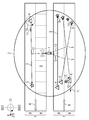
- Fig. 1 shows a traffic infrastructure in the form of a section of a four-lane highway.
- the illustrated section of the highway has two lanes 7, on which lanes 7 vehicles (not shown) move in each direction 6.
- Each lane 7 has two tracks 8 each.
- a receiving unit 1 is arranged in a region between the two lanes 8.
- a detection area 2 of the receiving unit 1 is formed in a specific case approximately circular and each covers a substantial part of the two lanes. 8
- Each of the vectors 3 includes a certain angle 10 with a reference vector 11.
- Each vector 3 has a normal distance 12 from the receiving unit 1.
- the fast lane 8 of the upper carriageway 7 is divided into seven sections 9. For two vectors 3 of the right-hand lane 8 of the lower lane 7, an averaged entry point 13 and an averaged exit point 14 are shown.
- a receiving unit according to the invention which performs a computer program for determining the geographical position of the lanes / tracks.
- a plurality of these vehicles transmit state data to the receiving unit 1 several times while passing through the detection area 2 of the receiving unit 1.
- this transmission of state data to the receiving unit 1 is done at a frequency of about 10 Hz, but depending on the technology used in each case for data transmission or device in the vehicles, frequencies are well below this typical value, possible.
- the frequency with which the measurement of the condition data in the vehicles takes place influences the quality of the range recognition according to the method.
- These status data contain at least one position of the vehicle and optionally the time of the measurement.
- the receiving unit 1 logs the time of a status data transmission of the vehicle and the status data does not include a time of the position measurement.
- the detection of the condition data by means of GPS and the transmission of the status data to the receiving unit 1 by means of ITS-G5 communication are regarded as a specific embodiment.
- the receiving unit 1 After the status data of N vehicles have been transmitted to the receiving unit 2 within a predetermined detection period, the receiving unit 1 evaluates the status data of the N vehicles by executing the next process steps. However, the transmission and reception of status data of future vehicles can continue in parallel, or even be interrupted.
- the receiving unit From the status data transmitted by the vehicles to the receiving unit 1, the receiving unit now determines the first received position 4 for each vehicle, which is identified as the position of the vehicle contained in the first status data transmission of the respective vehicle and the one last received Position 5 of the vehicle. The latter is called that position of the vehicle is identified which is included in the last state data transmission of the vehicle before the vehicle has left the detection area 2 again.
- the vector 3 is now calculated, which extends from the first received position 4 to the last received position 5 of the respective vehicle. For N vehicles which have crossed the detection area 2 during the detection period, there are now N vectors 3.
- the receiving unit 1 calculates the angle 10 which each of the vectors 3 includes with the reference vector 11, respectively. This can be accomplished, for example, by calculating the scalar product of the respective vector 3 with the reference vector 11. Of course, the reference vector 11 is always the same for all angle calculations.
- angle ranges are determined by which the N vectors 3 are divided according to their respective angle 10.
- one of the four vectors 3 shown has an angle 10 in the range between 3n / 2 and n / 2 (first angle range), and three vectors 3 each have an angle 10, which ranges between n / 2 and 3n / 2 (second angle range) is located.
- the vector 3 whose angle is in the first angular range, the first direction of travel 6 - and thus the upper lane 7 - assigned, and the other three vectors 3, the angle 10 each lie in the second angular range, the other direction of travel. 6 - And thus the lower lane. 7
- the all vectors 3 specifies one Clusters cover the geographical location of the lane 7.
- normal distance 12 between the respective vector 3 and the receiving unit 1, or any other reference point is calculated for each of the vectors 3 in one of the two clusters. Subsequently, normal distance ranges are determined, according to which the vectors 3 of this cluster are further subdivided according to their respective normal distance 12.
- a vector 3 has a shorter normal distance 12 and two vectors 3 a longer normal distance 12.
- the first cluster (the upper roadway 7) of the concrete embodiment is treated, where, however, only one vector 3 is shown in the concrete example.
- the sub-clusters of a cluster are now each assigned a track 8 of the lane 7 associated with the respective cluster.
- the entire detection area 2 of the receiving unit 1 can thus be divided into sections 9.
- the lanes 8 or lanes 7 of the traffic infrastructure which have just been determined offer themselves.
- these sections can be used to assign the status data, which are continuously transmitted to the receiving unit 1 by the vehicles in the detection area 2, not to a specific position but to one of these sections 9 and then to all status data associated with this section 9 to average the respective section 9.
Landscapes
- Physics & Mathematics (AREA)
- General Physics & Mathematics (AREA)
- Chemical & Material Sciences (AREA)
- Analytical Chemistry (AREA)
- Engineering & Computer Science (AREA)
- Radar, Positioning & Navigation (AREA)
- Remote Sensing (AREA)
- Traffic Control Systems (AREA)
Abstract
Die Erfindung betrifft ein Verfahren zur geographischen Bereichserkennung von Verkehrsinfrastruktur mittels einer im Bereich der Verkehrsinfrastruktur angeordneten Empfangseinheit für einen Erfassungsbereich der Empfangseinrichtung, wobei das Verfahren die folgenden Schritte umfasst: - Zustandsdaten von mehreren Fahrzeugen, welche Zustandsdaten jeweils zumindest eine Position des jeweiligen Fahrzeuges sowie gegebenenfalls einen Zeitpunkt der Positionsbestimmung umfassen, werden von den Fahrzeugen mehrmals während die Fahrzeuge den Erfassungsbereich (2) der Empfangseinrichtung (1) durchqueren, mittels drahtloser Kommunikation an die Empfangseinheit (1) übermittelt; - die Empfangseinheit (1), oder eine mit der Empfangseinheit verbundene Recheneinheit, berechnet für jedes Fahrzeug einen Vektor (3), wobei sich der Vektor (3) von einer ersten, insbesondere der als erste, empfangenen Position (4) des Fahrzeuges im Erfassungsbereich (2) bis zu einer zweiten, insbesondere der als letzte, empfangenen Position (5) des Fahrzeuges im Erfassungsbereich (2) erstreckt; - aus den Vektoren (3) aller Fahrzeuge bestimmt die Empfangseinheit (1) oder Recheneinheit Fahrtrichtungen (6) der Fahrzeuge sowie die geographische Lage von Fahrbahnen (7) und/oder Spuren (8) der Fahrbahnen (7) der Verkehrsinfrastruktur im Erfassungsbereich (2).The invention relates to a method for geographical area detection of traffic infrastructure by means of a receiving unit arranged in the area of the traffic infrastructure for a detection area of the receiving facility, the method comprising the following steps: State data of a plurality of vehicles, which state data each comprise at least one position of the respective vehicle and possibly a time of position determination, are passed by the vehicles several times while the vehicles pass through the detection area (2) of the receiving device (1) by means of wireless communication to the receiving unit ( 1) transmitted; - The receiving unit (1), or connected to the receiving unit arithmetic unit calculates a vector (3) for each vehicle, wherein the vector (3) of a first, in particular as the first, received position (4) of the vehicle in the detection area (2) extends to a second, in particular the last, received position (5) of the vehicle in the detection area (2); from the vectors (3) of all vehicles, the receiving unit (1) or arithmetic unit determines directions of travel (6) of the vehicles and the geographical position of lanes (7) and / or lanes (8) of the lanes (7) of the traffic infrastructure in the detection area (2 ).
Description
Die Erfindung betrifft ein Verfahren zur geographischen Bereichserkennung von Verkehrsinfrastruktur gemäß dem Oberbegriff von Anspruch 1.The invention relates to a method for geographical area recognition of traffic infrastructure according to the preamble of claim 1.
Dieses Verfahren ist zur Verwendung in so genannten Road Side Units (im Folgenden Empfangseinheiten genannt) geeignet, wobei diese Road Side Units Bestandteil eines kooperativen Systems sein können.This method is suitable for use in so-called road side units (hereinafter referred to as receiving units), these road side units can be part of a cooperative system.
Kooperative Systeme im Zusammenhang mit Verkehrsinfrastruktur sind Gegenstand intensiver aktueller Forschung und Entwicklung. Sie sollen es Straßenbetreibern, Verkehrsinfrastruktur, Fahrzeugen und deren Fahrern sowie anderen Straßenbenutzern ermöglichen, miteinander zu kooperieren, um eine möglichst effiziente, sichere und angenehme Fahrt zu ermöglichen.Cooperative systems related to transport infrastructure are the subject of intensive current research and development. They are designed to allow road operators, transport infrastructure, vehicles and their drivers, as well as other road users, to cooperate with each other to enable the most efficient, safe and enjoyable journey possible.
Dazu sind Systeme vorgesehen, die Kommunikation in Form von Datenaustausch zwischen Fahrzeugen und Infrastruktur ermöglichen. Solche Kommunikationssysteme sind beispielsweise unter den Akronymen V2R (Vehicle to Roadside) oder V2V (Vehicle to Vehicle) bekannt. Diese Kommunikationssysteme werden in Europa mit ITS-G5 und in den USA mit DSRC/WAVE abgekürzt.For this purpose, systems are provided which enable communication in the form of data exchange between vehicles and infrastructure. Such communication systems are known, for example, under the acronyms V2R (Vehicle to Roadside) or V2V (Vehicle to Vehicle). These communication systems are abbreviated to ITS-G5 in Europe and DSRC / WAVE in the US.
Die gegenständliche Erfindung betrifft den Bereich der V2R-Kommunikation, bei welcher üblicherweise sogenannte Common Awareness Messages (CAM) von den am Straßenverkehr teilnehmenden Fahrzeugen an Empfangseinheiten der Infrastruktur, sogenannte Road Side Units (R-ITS), übermittelt werden. Inhalt dieser CAM können verschiedenste verkehrsrelevante Daten sein, wie beispielsweise Informationen über die aktuelle Position und Geschwindigkeit des übermittelnden Fahrzeuges samt zugehörigem Zeitpunkt der Messung.The subject invention relates to the field of V2R communication, in which so-called Common Awareness Messages (CAM) are usually transmitted from the vehicles participating in the traffic to receiving units of the infrastructure, so-called Road Side Units (R-ITS). Content of this CAM can be a variety of traffic-related data, such as information about the current position and speed of the transmitting vehicle and the associated time of measurement.
Diese Daten werden üblicherweise von den Empfangseinheiten gesammelt, ausgewertet und an übergeordnete Verkehrsleitzentralen weitergesendet. Dort werden schließlich makroskopische, über gewissen Strecken- und Zeitabschnitte gemittelte Daten analysiert, wie beispielsweise Verkehrsdichten oder Reisegeschwindigkeiten in bestimmten Streckenabschnitten. Ebenso können auf diese Weise Stau- oder auch Unfallwarnungen generiert und ausgegeben werden.These data are usually collected by the receiving units, evaluated and forwarded to higher traffic control centers. Finally, macroscopic data averaged over certain sections of the route and time are analyzed there, such as traffic densities or travel speeds in certain sections of the route. Likewise, congestion or accident warnings can be generated and output in this way.
Die Kommunikation zwischen Fahrzeugen auf einem bestimmten Streckenabschnitt und der Empfangseinheit, die diesen Abschnitt überwacht, findet im Wesentlichen laufend, also mit hoher Frequenz der CAM-Übermittlungen, statt. Dabei beginnt die V2R-Kommunikation mit Eintritt des Fahrzeuges in den Erfassungsbereich einer Empfangseinheit und endet mit Verlassen dieses Erfassungsbereiches. Da die Strecke, welche ein Fahrzeug dabei üblicherweise innerhalb eines solchen Erfassungsbereiches zurücklegt, rund 1 km beträgt, und da innerhalb dieses Erfassungsbereiches häufig mehrere Wege (verschiedene Fahrbahnen bzw. Spuren von Fahrbahnen) befahrbar sind, ist es in manchen Fällen günstig, den gesamten Erfassungsbereich in mehrere Abschnitte zu unterteilen, innerhalb derer die gesammelten Daten gemittelt und zur Weitergabe an die übergeordneten Verkehrsleitzentralen aufbereitet werden.Communication between vehicles on a particular link and the receiving unit monitoring that section is essentially ongoing, that is, with high frequency CAM transmissions. In this case, the V2R communication begins when the vehicle enters the detection area of a receiving unit and ends when it leaves this detection area. Since the distance which a vehicle usually travels within such a detection range is approximately 1 km, and since several paths (various lanes or lanes of lanes) are frequently passable within this detection range, it is in some cases favorable to cover the entire detection range into several sections too within which the collected data is averaged and processed for distribution to the higher level traffic control centers.
Dazu war es bisher nötig, die geographische Topologie des Verkehrsbereiches jeweils manuell vor Inbetriebnahme der Empfangseinheit zu erfassen, in der Empfangseinheit zu konfigurieren und die entsprechenden Abschnitte, in die der gesamte Erfassungsbereich unterteilt werden soll, festzulegen. Eine solche Konfiguration und Erfassung ist sehr zeitaufwändig, daher kostenintensiv, und muss sehr genau vorgenommen werden. Außerdem muss dieser Prozess bei sich ändernden äußeren Gegebenheiten (z.B. nach Umbauarbeiten) bzw. beim Einsatz der Empfangseinheit in einem anderen Streckenabschnitt jedes Mal neu vorgenommen werden.For this purpose, it was previously necessary to manually detect the geographic topology of the traffic area before commissioning the receiving unit, to configure it in the receiving unit and to specify the corresponding sections into which the entire coverage area is to be subdivided. Such a configuration and acquisition is very time consuming, therefore costly, and must be done very accurately. In addition, this process must be re-made each time the environment changes (e.g., after rebuilding work) or when the receiving unit is used in another stretch of road.
Es ist daher eine Aufgabe der gegenständlichen Erfindung, ein Verfahren in Form eines Lernalgorithmus für eine Empfangseinheit eines kooperativen Systems bereitzustellen, welches die manuelle Erfassung und Konfiguration der Empfangseinheit obsolet werden lässt und einfach genug ist, um direkt auf der Empfangseinheit ausgeführt werden zu können.It is therefore an object of the subject invention to provide a method in the form of a learning algorithm for a receiving unit of a cooperative system, which makes the manual detection and configuration of the receiving unit obsolete and simple enough to be executed directly on the receiving unit.
Bei einem erfindungsgemäßen Verfahren zur geographischen Bereichserkennung von Verkehrsinfrastruktur mittels einer im Bereich der Verkehrsinfrastruktur angeordneten Empfangseinheit für einen Erfassungsbereich der Empfangseinheit, welches die folgenden Schritte umfasst:
- Zustandsdaten von mehreren Fahrzeugen, welche Zustandsdaten jeweils zumindest eine Position des jeweiligen Fahrzeuges sowie gegebenenfalls einen Zeitpunkt der Positionsbestimmung umfassen, werden von den Fahrzeugen mehrmals während die Fahrzeuge den Erfassungsbereich der Empfangseinrichtung durchqueren, mittels drahtloser Kommunikation an die Empfangseinheit übermittelt;
- die Empfangseinheit, oder eine mit der Empfangseinheit verbundene Recheneinheit, berechnet für jedes Fahrzeug einen Vektor, wobei sich der Vektor von einer ersten, insbesondere der als erste, empfangenen Position des Fahrzeuges im Erfassungsbereich bis zu einer zweiten, insbesondere der als letzte, empfangenen Position des Fahrzeuges im Erfassungsbereich erstreckt;
- aus den Vektoren aller Fahrzeuge bestimmt die Empfangseinheit oder Recheneinheit Fahrtrichtungen der Fahrzeuge sowie die geographische Lage von Fahrbahnen und/oder Spuren der Fahrbahnen der Verkehrsinfrastruktur im Erfassungsbereich.
- Condition data of a plurality of vehicles, which status data in each case comprise at least one position of the respective vehicle and optionally a time of position determination, are transmitted by the vehicles several times while the vehicles pass through the detection range of the receiving device by means of wireless communication to the receiving unit;
- the receiving unit, or a computing unit connected to the receiving unit, calculates a vector for each vehicle, wherein the vector of a first, in particular the first received position of the vehicle in the detection area to a second, in particular the last, received position of Vehicle extends in the detection area;
- From the vectors of all vehicles, the receiving unit or arithmetic unit determines directions of travel of the vehicles and the geographical location of lanes and / or lanes of the lanes of the traffic infrastructure in the detection area.
Dadurch wird ein Verfahren bereitgestellt, mittels welchem die Topologie der innerhalb des Erfassungsbereiches der Empfangseinheit vorhandenen Verkehrsströme ermittelt und dadurch auf die Topologie der von der Empfangseinheit überwachten Straßenzüge (im Speziellen und der Verkehrsinfrastruktur im Allgemeinen) geschlossen werden kann. Eine manuelle Erfassung der Topografie und Konfiguration der Empfangseinheit ist somit nicht mehr nötig. Insbesondere in Verbindung mit mobilen Empfangseinheiten, welche an ständig wechselnden Einsatzorten zur Verwendung kommen, impliziert das beschriebene Verfahren daher eine beträchtliche Einsparung an Kosten und Arbeitszeit.In this way, a method is provided by means of which the topology of the traffic streams present within the coverage area of the receiving unit can be determined and thereby closed on the topology of the roadways monitored by the receiving station (in particular, and the traffic infrastructure in general). Manual detection of the topography and configuration of the receiving unit is thus no longer necessary. Especially in connection with mobile receiving units, Therefore, the described method implies a considerable saving in costs and labor time, which are used in constantly changing locations.
Die für die Erfassung der Topographie notwendigen Rechenarbeiten können entweder von der jeweiligen Empfangseinheit selbst, oder von Recheneinheiten, welche mit den Empfangseinheiten beispielsweise mittels drahtloser Kommunikation verbunden sind, durchgeführt werden. Eine solche Recheneinheit kann z.B. ein sich in einiger Entfernung von der Empfangseinheit befindender Rechner sein, z.B. der Zentralrechner des kooperativen Systems.The arithmetic work necessary for the detection of the topography can be carried out either by the respective receiving unit itself or by arithmetic units which are connected to the receiving units, for example by means of wireless communication. Such a computing unit may e.g. a computer located some distance from the receiving unit, e.g. the central computer of the cooperative system.
Darüber hinaus besteht der Vorteil, dass das Verfahren mehrmals, vorzugsweise periodisch, ausgeführt werden kann, wodurch Ungenauigkeiten der Positionen der Fahrzeuge, welche üblicherweise aus einer gewissen Streuung unterliegenden GPS-Messungen bestimmt werden, kompensiert werden können.In addition, there is the advantage that the method can be carried out several times, preferably periodically, whereby it is possible to compensate for inaccuracies in the positions of the vehicles, which are usually determined from GPS measurements subject to a certain scatter.
Bei der Bestimmung des Vektors eines Fahrzeuges wird als Ursprungspunkt des Vektors eine erste Position des Fahrzeuges und als Endpunkt des Vektors eine zweite Position des Fahrzeuges im Empfangsbereich der Empfangseinheit gewählt. Da ein solcher Vektor näherungsweise die Bewegung des Fahrzeuges im Empfangsbereich repräsentieren soll, ist es zwar nicht zwingend notwendig, aber durchaus sinnvoll, dafür seine als erste (beim Eintritt in den Empfangsbereich) empfangene Position und seine als letzte (vor Verlassen des Empfangsbereichs) empfangene Position zu verwenden.When determining the vector of a vehicle, a first position of the vehicle is selected as the point of origin of the vector, and a second position of the vehicle in the receiving area of the receiving unit is selected as the end point of the vector. Since such a vector is approximately to represent the movement of the vehicle in the reception area, it is not absolutely necessary, but quite reasonable, but its as the first (when entering the reception area) received position and its last (before leaving the reception area) received position to use.
Bei einer bevorzugten Ausführungsform des erfindungsgemäßen Verfahrens ist es vorgesehen, dass die Fahrtrichtungen der Fahrzeuge bestimmt werden, indem die Vektoren aller Fahrzeuge entsprechend einem Winkel, welchen der jeweilige Vektor mit einem Referenzvektor einschließt, gruppiert werden.In a preferred embodiment of the method according to the invention, it is provided that the directions of travel of the vehicles are determined by the vectors of all vehicles according to an angle, which the respective vector includes with a reference vector, are grouped.
Dadurch wird eine besonders einfache und rechnerisch unaufwändige Methode zur Bestimmung der Fahrtrichtungen der Fahrzeuge bereitgestellt. Die Berechnung des Winkels zwischen dem jeweiligen Vektor des Fahrzeuges und dem Referenzvektor kann beispielsweise mittels Berechnung des Skalarproduktes der beiden Vektoren ermittelt werden. Anschließend werden alle Vektoren in Cluster unterteilt, deren Anzahl mit der Anzahl derjenigen Richtungen übereinstimmt, in welche sich die erfassten Verkehrsströme bewegen.As a result, a particularly simple and computationally uncomplicated method for determining the directions of travel of the vehicles is provided. The calculation of the angle between the respective vector of the vehicle and the reference vector can be determined, for example, by calculating the scalar product of the two vectors. Subsequently, all vectors are divided into clusters, the number of which coincides with the number of directions in which the detected traffic flows.
Dabei kann vorgesehen sein, dass bei der Bestimmung der Fahrtrichtungen der Fahrzeuge jeweils ein bestimmter Winkelbereich einer bestimmten Fahrtrichtung zugeordnet wird.It can be provided that in the determination of the directions of travel of the vehicles each a certain angular range of a particular direction of travel is assigned.
Ein voller Winkel (2π) kann dabei in beispielsweise zwei Bereiche unterteilt werden, nämlich in einen ersten Bereich (zwischen 3n/2 und n/2) sowie in einen zweiten Bereich (zwischen π/2 und 3π/2). Je nachdem in welchen der beiden Bereiche der Winkel eines bestimmten Vektors fällt, wird dem zugeordneten Fahrzeug nun eine von zwei Richtungen zugeordnet. Im Falle einer vierspurigen Autobahn (zwei Spuren je Fahrtrichtung) würden sich somit zwei Cluster von Vektoren ergeben - ein Cluster pro Fahrtrichtung. Bei komplizierteren Topologien wären weitere Unterteilungen des vollen Winkels nötig.A full angle (2π) can be divided into, for example, two areas, namely a first area (between 3n / 2 and n / 2) and a second area (between π / 2 and 3π / 2). Depending on in which of the two areas the angle of a particular vector falls, the assigned vehicle is now assigned one of two directions. In the case of a four-lane highway (two lanes per direction of travel), two clusters of vectors would result - one cluster per direction of travel. For more complex topologies, further subdivisions of the full angle would be necessary.
Zusätzlich kann vorgesehen sein, dass die Fahrbahnen und/oder Spuren der Fahrbahnen der Verkehrsinfrastruktur bestimmt werden, indem die Vektoren aller Fahrzeuge entsprechend einem Normalabstand der Empfangseinheit von dem jeweiligen Vektor gruppiert werden.In addition, it can be provided that the roadways and / or lanes of the traffic infrastructure lanes are determined by grouping the vectors of all vehicles corresponding to a normal distance of the receiving unit from the respective vector.
Diese Einteilung der Vektoren nach ihrem jeweiligen Normalabstand von der Empfangseinheit führt zu einer höheren örtlichen Auflösung der einzelnen Verkehrsströme. Waren die Vektoren der Fahrzeuge auf der weiter oben als Beispiel angeführten vierspurigen Autobahn bisher lediglich jeweils einem von zwei Clustern (ein Cluster pro Fahrtrichtung) zugeordnet, so führt diese bevorzugte Ausführungsform des erfindungsgemäßen Verfahrens zu einer Zuordnung eines Vektors zu einem von insgesamt vier Clustern - einem Cluster pro Spur der Autobahn.This division of the vectors according to their respective normal distance from the receiving unit leads to a higher spatial resolution of the individual traffic streams. Whereas the vectors of the vehicles on the four-lane highway given above as an example have hitherto only been assigned to one of two clusters (one cluster per direction of travel), this preferred embodiment of the method according to the invention leads to an assignment of one vector to one of a total of four clusters Cluster per lane of the highway.
Bei einer bevorzugten Ausführungsform des erfindungsgemäßen Verfahrens ist es vorgesehen, dass für jede Fahrbahn und/oder Spur der Fahrbahnen ein gemittelter Eintrittspunkt sowie ein gemittelter Austrittspunkt derjenigen Fahrzeuge, die diese Fahrbahn bzw. Spur befahren, bestimmt werden.In a preferred embodiment of the method according to the invention, it is provided that for each lane and / or lane of the lanes, an averaged entry point and an averaged exit point of those vehicles that drive on this lane or lane are determined.
Bei genügend hoher Anzahl der am Verfahren beteiligten Fahrzeuge entsprechen diese gemittelten Ein- und Austrittspunkte in guter Näherung der Mitte der jeweiligen Fahrbahn bzw. der jeweiligen Spur der Fahrbahn. Somit ist der Zusammenhang zwischen den erfassten Verkehrsströmen innerhalb des Erfassungsbereiches der Empfangseinheit und der Topologie der durch die Empfangseinheit überwachten Verkehrsinfrastruktur hergestellt.With a sufficiently high number of vehicles involved in the process, these averaged entry and exit points correspond in good approximation to the center of the respective roadway or the respective lane of the roadway. Thus, the relationship between the detected traffic streams is established within the coverage area of the receiving unit and the topology of the traffic infrastructure monitored by the receiving unit.
Bei einer bevorzugten Ausführungsform des erfindungsgemäßen Verfahrens ist es vorgesehen, dass die Zustandsdatenerfassung durch die Fahrzeuge erfolgt.In a preferred embodiment of the method according to the invention, it is provided that the state data acquisition is performed by the vehicles.
Eigens zur Zustandsdatenerfassung vorgesehene Einrichtungen sind somit überflüssig. Dabei hat beispielsweise die Zustandsdatenerfassung mittels GPS-Technologie den zusätzlichen Vorteil, dass üblicherweise in Fahrzeugen vorhandene Gerätschaften, wie beispielsweise Navigationssysteme oder Mobiltelefone, zur Erfassung der Zustandsdaten verwendet werden können. Selbstverständlich können auch andere Navigationssysteme verwendet werden, wie z.B. Galileo.Specially designed for state data acquisition facilities are therefore superfluous. For example, state data acquisition using GPS technology has the additional advantage that commonly existing in vehicles equipment, such as navigation systems or mobile phones, can be used to capture the status data. Of course, other navigation systems can be used, such as Galileo.
Die Verwendung von weit verbreiteten und etablierten Technologien ist auch eine fundamentale Idee des Konzeptes kooperativer Systeme, da solche Systeme nur dann sinnvoll sind, wenn möglichst viele Verkehrsteilnehmer miteinander kommunizieren. So geschieht vorzugsweise auch die Übermittlung der durch die Fahrzeuge erfassten Daten an die Empfangseinheit mittels weit verbreiteter Technologien der drahtlosen Kommunikation, wie z.B. ITS-G5, DSRC/WAVE, Mobilfunk, oder WLAN.The use of widely used and established technologies is also a fundamental idea of the concept of cooperative systems, since such systems are meaningful only if as many road users as possible communicate with each other. Thus, preferably, the transmission of the data captured by the vehicles to the receiving unit is also done by means of widely used wireless communication technologies, such as e.g. ITS-G5, DSRC / WAVE, cellular, or WLAN.
Bei einer weiteren bevorzugten Ausführungsform des erfindungsgemäßen Verfahrens ist es vorgesehen, dass die Übermittlung der Zustandsdaten an die Empfangseinheit periodisch geschieht, z.B. mit einer Frequenz von 0,1 Hz bis 100 Hz.In a further preferred embodiment of the method according to the invention, it is provided that the transmission of the status data to the receiving unit takes place periodically, e.g. with a frequency of 0.1 Hz to 100 Hz.
Abhängig von der Größe des jeweiligen Erfassungsbereiches sowie von der mittleren Geschwindigkeit der Fahrzeuge, welche die Verkehrsinfrastruktur in diesem Bereich befahren, wird die Frequenz der Zustandsdatenübermittlung vorzugsweise so gewählt, dass die mit der als erste bzw. als letzte empfangenen Position der Fahrzeuge identifizierten Positionen möglichst gut mit den tatsächlichen Ein- und Austrittspunkten der Fahrzeuge in den und aus dem Erfassungsbereich der Empfangseinheit übereinstimmen.Depending on the size of the respective coverage area as well as on the average speed of the vehicles that drive the traffic infrastructure in this area, the frequency of the status data transmission is preferably chosen so that the positions identified as the first or last received position of the vehicles are as good as possible coincide with the actual entry and exit points of the vehicles into and out of the coverage area of the receiving unit.
Bei einer bevorzugten Ausführungsform des erfindungsgemäßen Verfahrens ist es vorgesehen, dass die als letzte empfangene Position diejenige Position des Fahrzeuges ist, nach deren Übermittlung an die Empfangseinheit für einen festgelegten Zeitraum keine weiteren Zustandsdaten dieses Fahrzeuges die Empfangseinheit erreicht haben.In a preferred embodiment of the method according to the invention, it is provided that the last position received is that position of the vehicle, after its transmission to the receiving unit for a fixed period no further status data of this vehicle have reached the receiving unit.
Wiederum handelt es sich hierbei um eine besonders einfache und mit wenig rechnerischem Aufwand verbundene Methode, um die als letzte empfangene Position des Fahrzeuges zu bestimmen. Nach dem Verstreichen einer bestimmten, vorzugsweise mit der Frequenz der Zustandsdatenübermittlung in Zusammenhang stehenden, Zeitspanne, wird diejenige Position des Fahrzeuges als seine als letzte empfangene Position identifiziert, welche in den letzten empfangenen Zustandsdaten des Fahrzeuges enthalten war. Je höher die Frequenz der Datenübermittlung ist, desto größer ist die Wahrscheinlichkeit, dass die als letzte empfangene Position des Fahrzeuges mit derjenigen Position, an welcher das Fahrzeug den Erfassungsbereich verlässt, übereinstimmt.Again, this is a particularly simple and with little computational effort associated method to determine the last received position of the vehicle. After elapse of a certain period of time, preferably associated with the frequency of status data transmission, that position of the vehicle is identified as its last received position contained in the last received condition data of the vehicle. The higher the frequency of the data transmission, the greater the probability that the last received position of the vehicle coincides with the position at which the vehicle leaves the detection area.
Bei einer bevorzugten Ausführungsform des erfindungsgemäßen Verfahrens ist es vorgesehen, dass die Genauigkeit des Verfahrens durch Verwendung zusätzlicher Topologie-Informationen erhöht wird.In a preferred embodiment of the method according to the invention, it is provided that the accuracy of the method is increased by using additional topology information.
Insbesondere ist vorgesehen, dass Informationen über die Topologie der Verkehrsinfrastruktur aus anderen Quellen genützt werden, um die Genauigkeit der geographischen Bereichserkennung zu erhöhen. Beispielsweise könnten via MAP-Telegramm übertragene Informationen aus Mobilfunknetzen dabei miteinbezogen werden.In particular, it is envisaged that information about the topology of the traffic infrastructure from other sources will be used to increase the accuracy of geographic area recognition. For example, information transmitted via MAP telegram from mobile networks could be included.
Bei einer bevorzugten Ausführungsform des erfindungsgemäßen Verfahrens ist es vorgesehen, dass die Empfangseinheit oder Recheneinheit den maximalen Erfassungsbereich in mehrere Abschnitte unterteilt.In a preferred embodiment of the method according to the invention, it is provided that the receiving unit or arithmetic unit subdivides the maximum detection area into a plurality of sections.
Insbesondere für den regulären Betrieb der Empfangseinheit nach der Kalibrierung sieht diese bevorzugte Ausführungsform die Unterteilung des Empfangsbereiches in mehrere Abschnitte vor. So kann im Falle des Beispiels der vierspurigen Autobahn der Empfangsbereich so unterteilt werden, dass jeder Spur ein eigener Abschnitt zugeordnet ist. Darüber hinaus ist es ebenso möglich die einzelnen Spuren normal zur Fahrtrichtung in weitere Abschnitte zu unterteilen, was insbesondere dann sinnvoll ist, wenn der Erfassungsbereich besonders groß ist und/oder dann, wenn die Topologie der zu erfassenden Verkehrsinfrastruktur besonders kompliziert ist. Diese Abschnitte dienen dann als Bereiche, innerhalb derer im Normalbetrieb der Empfangseinheit nach der Kalibrierung bestimmte Zustandsdaten gemittelt werden.In particular, for the regular operation of the receiving unit after calibration, this preferred embodiment provides for the division of the receiving area into several sections. Thus, in the case of the example of the four-lane highway, the reception area can be subdivided so that each lane is assigned a separate section. Moreover, it is also possible to divide the individual tracks normal to the direction of travel in further sections, which is particularly useful if the detection area is particularly large and / or if the topology of the traffic infrastructure to be detected is particularly complicated. These sections then serve as areas within which certain condition data are averaged during calibration of the receiving unit after calibration.
Darüber hinaus ist eine Empfangseinheit zur Verwendung in einem der oben beschriebenen Verfahren vorgesehen, wobei
- die Empfangseinheit ausgebildet ist, um Zustandsdaten von mehreren Fahrzeugen, welche Zustandsdaten jeweils zumindest eine Position des jeweiligen Fahrzeuges sowie gegebenenfalls einen Zeitpunkt der Positionsbestimmung umfassen und von den Fahrzeugen mehrmals während die Fahrzeuge den Erfassungsbereich der Empfangseinrichtung durchqueren mittels drahtloser Kommunikation an die Empfangseinheit übermittelt werden, zu empfangen, und
- die Empfangseinheit, oder eine mit der Empfangseinheit verbundene Recheneinheit, ausgebildet ist, um für jedes Fahrzeug einen Vektor zu berechnen, wobei sich der Vektor von einer ersten, insbesondere von der als erste, empfangenen Position des Fahrzeuges im Erfassungsbereich bis zu einer zweiten, insbesondere der als letzte, empfangenen Position des Fahrzeuges im Erfassungsbereich erstreckt, und
- die Empfangseinheit oder die Recheneinheit ausgebildet ist, um aus den Vektoren aller Fahrzeuge Fahrtrichtungen der Fahrzeuge sowie die geographische Lage von Fahrbahnen und/oder Spuren der Fahrbahnen der Verkehrsinfrastruktur im Erfassungsbereich zu bestimmen.
- the receiving unit is configured to transmit status data from a plurality of vehicles, which status data in each case comprise at least one position of the respective vehicle and optionally a time of position determination and by the vehicles several times while the vehicles pass through the detection range of the receiving device by means of wireless communication to the receiving unit receive, and
- the receiving unit, or a computing unit connected to the receiving unit, is designed to calculate a vector for each vehicle, wherein the vector of a first, in particular the first received position of the vehicle in the detection area to a second, in particular the extends as the last received position of the vehicle in the detection area, and
- the receiving unit or the computing unit is designed to determine from the vectors of all vehicles directions of travel of the vehicles as well as the geographical position of lanes and / or lanes of the lanes of the traffic infrastructure in the detection area.
Eine solche erfindungsgemäße Empfangseinheit ist geeignet, als Empfangseinheit in einem der oben beschriebenen Verfahren zu fungieren.Such a receiving unit according to the invention is suitable for functioning as a receiving unit in one of the methods described above.
Des Weiteren ist ein Computerprogrammprodukt vorgesehen, welches ein Computerprogramm umfasst und direkt in einen Speicher der oben beschriebenen Empfangseinheit, oder in den Speicher einer der Empfangseinheit zugeordneten Recheneinheit ladbar ist, mit Computerprogramm-Mitteln, um alle Schritte erfindungsgemäßen Verfahrens auszuführen, wenn das Computerprogramm von der Empfangseinheit, oder der Recheneinheit ausgeführt wird.Furthermore, a computer program product is provided, which comprises a computer program and can be loaded directly into a memory of the above-described receiving unit, or into the memory of a processing unit associated with the receiving unit, with computer program means for carrying out all the steps according to the invention when the computer program is executed by the computer Receiving unit, or the arithmetic unit is executed.
Da es sich bei dem erfindungsgemäßen Verfahren um ein Verfahren handelt, im Rahmen dessen unter Umständen große Datenmengen verarbeitet werden müssen, bietet sich eine Implementierung des Verfahrens als Computerprogramm an.Since the method according to the invention is a method in which, under certain circumstances, large amounts of data have to be processed, an implementation of the method is suitable as a computer program.
Die Erfindung wird nun anhand eines Ausführungsbeispiels näher erläutert. Die Zeichnung ist beispielhaft und soll den Erfindungsgedanken zwar darlegen, ihn aber keinesfalls einengen oder gar abschließend wiedergeben. Dabei zeigt:
- Fig. 1
- eine schematische Darstellung einer Verkehrsinfrastruktur in Form einer vierspurigen Autobahn welche von einer erfindungsgemäßen Empfangseinheit überwacht wird.
- Fig. 1
- a schematic representation of a traffic infrastructure in the form of a four-lane highway which is monitored by a receiving unit according to the invention.
Fig. 1 zeigt eine Verkehrsinfrastruktur in Form eines Abschnittes einer vierspurigen Autobahn. Der dargestellte Abschnitt der Autobahn weist zwei Fahrbahnen 7 auf, auf welchen Fahrbahnen 7 sich Fahrzeuge (nicht dargestellt) in jeweils eine Richtung 6 bewegen. Dabei weist jede Fahrbahn 7 jeweils zwei Spuren 8 auf.Fig. 1 shows a traffic infrastructure in the form of a section of a four-lane highway. The illustrated section of the highway has two lanes 7, on which lanes 7 vehicles (not shown) move in each
In einem Bereich zwischen den beiden Fahrbahnen 8 ist eine Empfangseinheit 1 angeordnet. Ein Erfassungsbereich 2 der Empfangseinheit 1 ist im konkreten Fall annähernd kreisförmig ausgebildet und überdeckt jeweils einen wesentlichen Teil der beiden Fahrbahnen 8.In a region between the two
Innerhalb des Erfassungsbereiches 2 sind vier Vektoren 3 abgebildet, welche sich jeweils von einer als erste empfangenen Position 4 bis zu einer als letzte empfangenen Position 5 eines Fahrzeuges erstrecken. Jeder der Vektoren 3 schließt einen bestimmten Winkel 10 mit einem Referenzvektor 11 ein. Jeder Vektor 3 weist einen Normalabstand 12 von der Empfangseinheit 1 auf.Within the
Im konkreten Fall ist die Überholspur 8 der oberen Fahrbahn 7 in sieben Abschnitte 9 unterteilt. Für zwei Vektoren 3 der rechten Spur 8 der unteren Fahrbahn 7 sind ein gemittelter Eintrittspunkt 13 und ein gemittelter Austrittspunkt 14 dargestellt.In the specific case, the
Bei der Empfangseinheit 1 in Fig. 1 handelt es sich um eine erfindungsgemäße Empfangseinheit, welche zur Bestimmung der geographischen Lage der Fahrbahnen/Spuren ein Computerprogramm ausführt.In the receiving unit 1 in Fig. 1 is a receiving unit according to the invention, which performs a computer program for determining the geographical position of the lanes / tracks.
Auf der oberen und unteren Fahrbahn 7 des in Fig. 1 dargestellten Autobahnabschnittes bewegen sich Fahrzeuge jeweils in eine von insgesamt zwei möglichen Fahrtrichtungen 6. Dafür stehen auf jeder Fahrbahn 7 zwei Spuren 8 zur Verfügung.On the upper and lower lanes 7 of the highway section shown in FIG. 1, vehicles each move into one of a total of two possible directions of
Erfindungsgemäß ist es vorgesehen, dass mehrere dieser Fahrzeuge mehrmals, während sie den Erfassungsbereich 2 der Empfangseinheit 1 durchqueren, Zustandsdaten an die Empfangseinheit 1 übermitteln. Typischerweise geschieht diese Übermittlung von Zustandsdaten an die Empfangseinheit 1 mit einer Frequenz von etwa 10 Hz, abhängig von der jeweils zur Datenübermittlung eingesetzten Technologie bzw. Vorrichtung in den Fahrzeugen sind jedoch auch Frequenzen, die deutlich unter diesem typischen Wert liegen, möglich.According to the invention, it is provided that a plurality of these vehicles transmit state data to the receiving unit 1 several times while passing through the
Die Frequenz, mit welcher die Messung der Zustandsdaten in den Fahrzeugen geschieht, beeinflusst dabei in gewisser Weise die Qualität der verfahrensgemäßen Bereichserkennung. Je höher diese Frequenz, insbesondere die Frequenz der Positionsmessung, ist, desto näher liegen die als erste empfangene Position 4 und die als letzte empfangene Position 5 des Fahrzeuges an derjenigen Position, an welcher das Fahrzeug in den Erfassungsbereich 2 der Empfangseinheit 1 einfährt bzw. den Erfassungsbereich 2 wieder verlässt.The frequency with which the measurement of the condition data in the vehicles takes place, in a certain way, influences the quality of the range recognition according to the method. The higher this frequency, especially the frequency of the Position measurement, is, the closer are the first
Diese Zustandsdaten enthalten zumindest eine Position des Fahrzeuges sowie gegebenenfalls den Zeitpunkt der Messung. Denkbar ist jedoch ebenso, dass die Empfangseinheit 1 den Zeitpunkt einer Zustandsdatenübermittlung des Fahrzeuges protokolliert und die Zustandsdaten keinen Zeitpunkt der Positionsmessung umfassen.These status data contain at least one position of the vehicle and optionally the time of the measurement. However, it is also conceivable that the receiving unit 1 logs the time of a status data transmission of the vehicle and the status data does not include a time of the position measurement.
Im konkreten Ausführungsbeispiel geschieht die Erfassung der Zustandsdaten mittels GPS und die Übermittlung der Zustandsdaten an die Empfangseinheit 1 mittels ITS-G5-Kommunikation.In the specific embodiment, the detection of the condition data by means of GPS and the transmission of the status data to the receiving unit 1 by means of ITS-G5 communication.
Nachdem die Zustandsdaten von N Fahrzeugen innerhalb einer vorgegebenen Erfassungszeitspanne an die Empfangseinheit 2 übermittelt worden sind, wertet die Empfangseinheit 1 die Zustandsdaten der N Fahrzeuge aus, indem die nächsten Verfahrensschritte ausgeführt werden. Die Übermittlung und der Empfang von Zustandsdaten nachkommender Fahrzeuge können jedoch parallel dazu weiterlaufen, oder auch unterbrochen werden.After the status data of N vehicles have been transmitted to the receiving
Aus den von den Fahrzeugen an die Empfangseinheit 1 übermittelten Zustandsdaten ermittelt die Empfangseinheit nun für jedes Fahrzeug die als erste empfangene Position 4, welche als diejenige Position des Fahrzeuges identifiziert wird, welche in der ersten Zustandsdatenübermittlung des jeweiligen Fahrzeuges enthalten ist, sowie die als letzte empfangene Position 5 des Fahrzeuges. Letztere wird als diejenige Position des Fahrzeuges identifiziert, welche in der letzten Zustandsdatenübermittlung des Fahrzeuges, bevor das Fahrzeug den Erfassungsbereich 2 wieder verlassen hat, enthalten ist.From the status data transmitted by the vehicles to the receiving unit 1, the receiving unit now determines the first
Für jedes Fahrzeug wird nun der Vektor 3 berechnet, welcher sich von der als erste empfangenen Position 4 bis an die als letzte empfangene Position 5 des jeweiligen Fahrzeuges erstreckt. Für N Fahrzeuge, welche den Erfassungsbereich 2 während der Erfassungszeitspanne durchquert haben, liegen nun also N Vektoren 3 vor.For each vehicle, the
Als Nächstes berechnet die Empfangseinheit 1 den Winkel 10, welchen jeder der Vektoren 3 jeweils mit dem Referenzvektor 11 einschließt. Dies kann beispielsweise durch Berechnung des Skalarproduktes des jeweiligen Vektors 3 mit dem Referenzvektor 11 bewerkstelligt werden. Der Referenzvektor 11 ist dabei natürlich für alle Winkelberechnungen stets derselbe.Next, the receiving unit 1 calculates the
Nun werden Winkelbereiche bestimmt, nach welchen die N Vektoren 3 entsprechend ihrem jeweiligen Winkel 10 unterteilt werden. Im konkreten Beispiel weist einer der insgesamt vier dargestellten Vektoren 3 einen Winkel 10 im Bereich zwischen 3n/2 und n/2 (erster Winkelbereich) auf, und drei Vektoren 3 jeweils einen Winkel 10, welcher im Bereich zwischen n/2 und 3n/2 (zweiter Winkelbereich) liegt.Now, angle ranges are determined by which the
Entsprechend dieser Unterteilung wird dem Vektor 3, dessen Winkel 10 im ersten Winkelbereich liegt, die erste Fahrtrichtung 6 - und somit die obere Fahrbahn 7 - zugeordnet, und den anderen drei Vektoren 3, deren Winkel 10 jeweils im zweiten Winkelbereich liegen, die andere Fahrtrichtung 6 - und somit die untere Fahrbahn 7.According to this subdivision, the
Es gibt also nun zwei Cluster von Vektoren 3, wobei N1 Vektoren 3 dem ersten Cluster und N2 Vektoren 3 dem zweiten Cluster zugeordnet sind, und wobei N1 + N2 = N. Dabei legt derjenige geographische Bereich, den alle Vektoren 3 eines Clusters überstreichen, die geographische Lage der Fahrbahn 7 fest.Thus, there are now two clusters of
Nun wird für alle Vektoren 3 in einem der beiden Cluster jeweils der Normalabstand 12 zwischen dem jeweiligen Vektor 3 und der Empfangseinheit 1, oder einem beliebigen anderen Referenzpunkt, berechnet. Anschließend werden Normalabstandsbereiche bestimmt, nach welchen die Vektoren 3 dieses Clusters entsprechend ihrem jeweiligen Normalabstand 12 weiter unterteilt werden.Now the
Betrachtet man beispielsweise die Menge N2 der im konkreten Ausführungsbeispiel dem zweiten Cluster zugeordneten Vektoren 3, so weist ein Vektor 3 einen kürzeren Normalabstand 12 und zwei Vektoren 3 einen längeren Normalabstand 12 auf. Entsprechend wird der zweite Cluster selbst in zwei Subcluster mit N2,' Vektoren 3 im ersten Subcluster bzw. N2" im zweiten Subcluster unterteilt, wobei N2' + N2" = N2.Considering, for example, the set N 2 of the vectors assigned to the second cluster in the specific embodiment, a
Analog wird der erste Cluster (die obere Fahrbahn 7) des konkreten Ausführungsbeispiels behandelt, wo aber im konkreten Beispiel nur ein Vektor 3 dargestellt ist.Analogously, the first cluster (the upper roadway 7) of the concrete embodiment is treated, where, however, only one
Den Subclustern eines Clusters wird nun jeweils eine Spur 8 der mit dem jeweiligen Cluster assoziierten Fahrbahn 7 zugeordnet.The sub-clusters of a cluster are now each assigned a
Um nun von den während der Erfassungszeitspanne vollständig erfassten Verkehrsströmen innerhalb des Erfassungsbereiches 2 auf die geographische Lage der entsprechenden Verkehrsinfrastrukturen schließen zu können, bedarf es eines weiteren Verfahrensschrittes, der so aussehen kann: Aus der Menge der einem bestimmten Subcluster - und damit einer bestimmten Fahrspur 8 einer Fahrbahn 7 - zugeordneten Vektoren 3 wird der gemittelte Eintrittspunkt 13 sowie der gemittelte Austrittspunkt 14 aller diesem Subcluster zugeordneten Fahrzeuge bestimmt.In order now to determine from the traffic flows within the
Im konkreten Ausführungsbeispiel ist dies für die beiden dem zweigestrichenen Subcluster N2" des zweiten Clusters N2 dargestellt. Diese gemittelten Ein- 13 und Austrittspunkte 14 werden nun mit denjenigen Punkten identifiziert, an welchen die Fahrzeuge in den dem Subcluster des Clusters zugeordneten Abschnitt der Spur 8 eintreten bzw. diesen Abschnitt der Spur 8 wieder verlassen. Zwischen diesen beiden gemittelten Ein-13 und Austrittspunkten 14 kann nun wiederum ein Vektor gebildet werden, welcher den modellierten Verlauf der entsprechenden Spur 8 repräsentiert.In the concrete exemplary embodiment, this is illustrated for the two two-pointed subcluster N 2 "of the second cluster N 2. These averaged in and out points 14 are now identified with those points at which the vehicles in the section of the track assigned to the subcluster of the
Der gesamte Erfassungsbereich 2 der Empfangseinheit 1 kann somit in Abschnitte 9 unterteilt werden. Dafür bieten sich einerseits die gerade ermittelten Spuren 8 bzw. Fahrbahnen 7 der Verkehrsinfrastruktur selbst an. Andererseits ist es auch möglich, einzelne Streckenabschnitte, wie beispielsweise die Überholspur 8 der oberen Fahrbahn 7 in weitere Längsabschnitte 9 zu unterteilen. Diese Abschnitte können bei Normalbetrieb der Empfangseinheit 1 dazu verwendet werden, die Zustandsdaten, welche von den Fahrzeugen im Erfassungsbereich 2 ständig an die Empfangseinheit 1 übermittelt werden, nicht einer bestimmten Position sondern eben einem dieser Abschnitte 9 zuzuordnen und anschließend alle diesem Abschnitt 9 zugeordneten Zustandsdaten über den jeweiligen Abschnitt 9 zu mitteln.The
- 11
- Empfangseinheitreceiver unit
- 22
- Erfassungsbereichdetection range
- 33
- Vektorvector
- 44
- als erste empfangene Positionas the first received position
- 55
- als letzte empfangene Positionas last received position
- 66
- Fahrtrichtungdirection of travel
- 77
- Fahrbahnroadway
- 88th
- Spur der Fahrbahn 7Lane of the lane 7
- 99
- einer der N Abschnitte (Längsabschnitte) der Spur 8one of the N sections (longitudinal sections) of the track 8th
- 1010
- Winkelangle
- 1111
- Referenzvektorreference vector
- 1212
- Normalabstandnormal distance
- 1313
- gemittelter Eintrittspunktaveraged entry point
- 1414
- gemittelter Austrittspunktaveraged exit point
Claims (12)
Applications Claiming Priority (1)
| Application Number | Priority Date | Filing Date | Title |
|---|---|---|---|
| DE102015214955 | 2015-08-05 |
Publications (2)
| Publication Number | Publication Date |
|---|---|
| EP3128495A1 true EP3128495A1 (en) | 2017-02-08 |
| EP3128495B1 EP3128495B1 (en) | 2022-04-13 |
Family
ID=56611199
Family Applications (1)
| Application Number | Title | Priority Date | Filing Date |
|---|---|---|---|
| EP16182286.1A Active EP3128495B1 (en) | 2015-08-05 | 2016-08-02 | Method for geographical area detection of transportation infrastructure |
Country Status (2)
| Country | Link |
|---|---|
| US (1) | US10269241B2 (en) |
| EP (1) | EP3128495B1 (en) |
Cited By (1)
| Publication number | Priority date | Publication date | Assignee | Title |
|---|---|---|---|---|
| DE102018202970A1 (en) * | 2018-02-28 | 2019-08-29 | Robert Bosch Gmbh | Method for determining topological information of a road intersection |
Families Citing this family (3)
| Publication number | Priority date | Publication date | Assignee | Title |
|---|---|---|---|---|
| CN114841919A (en) * | 2022-03-22 | 2022-08-02 | 中国路桥工程有限责任公司 | Intelligent maintenance method for traffic infrastructure |
| CN115512552B (en) * | 2022-09-15 | 2023-09-26 | 云控智行科技有限公司 | Traffic flow statistics method, device and equipment |
| CN116524444B (en) * | 2023-04-10 | 2023-12-15 | 盐城工学院 | Traffic safety risk diagnosis method and device based on target detection |
Citations (4)
| Publication number | Priority date | Publication date | Assignee | Title |
|---|---|---|---|---|
| DE102013205057B3 (en) * | 2013-03-21 | 2014-08-28 | Siemens Aktiengesellschaft | Method for operating a stationary device and stationary device within a system for communication |
| US20140358414A1 (en) * | 2013-06-01 | 2014-12-04 | Faroog Ibrahim | System and method for creating, storing, and updating local dynamic MAP database with safety attribute |
| DE102013227144A1 (en) * | 2013-12-23 | 2014-12-11 | Siemens Aktiengesellschaft | Traffic communication station and method for operating a traffic communication station |
| DE102013107960A1 (en) * | 2013-07-25 | 2015-01-29 | Deutsches Zentrum für Luft- und Raumfahrt e.V. | Process for updating a database, as well as equipment and computer program |
Family Cites Families (4)
| Publication number | Priority date | Publication date | Assignee | Title |
|---|---|---|---|---|
| WO2011134083A1 (en) * | 2010-04-28 | 2011-11-03 | Ryerson University | System and methods for intraoperative guidance feedback |
| DE102010049091A1 (en) * | 2010-10-21 | 2012-04-26 | Gm Global Technology Operations Llc (N.D.Ges.D. Staates Delaware) | Method for operating at least one sensor of a vehicle and vehicle with at least one sensor |
| GB201221150D0 (en) | 2012-11-23 | 2013-01-09 | Tomtom Belgium Nv | Method of extracting gps traces to display driving trajectories through an area over one or more junctions |
| US20140302774A1 (en) * | 2013-04-04 | 2014-10-09 | General Motors Llc | Methods systems and apparatus for sharing information among a group of vehicles |
-
2016
- 2016-08-02 EP EP16182286.1A patent/EP3128495B1/en active Active
- 2016-08-04 US US15/228,015 patent/US10269241B2/en active Active
Patent Citations (4)
| Publication number | Priority date | Publication date | Assignee | Title |
|---|---|---|---|---|
| DE102013205057B3 (en) * | 2013-03-21 | 2014-08-28 | Siemens Aktiengesellschaft | Method for operating a stationary device and stationary device within a system for communication |
| US20140358414A1 (en) * | 2013-06-01 | 2014-12-04 | Faroog Ibrahim | System and method for creating, storing, and updating local dynamic MAP database with safety attribute |
| DE102013107960A1 (en) * | 2013-07-25 | 2015-01-29 | Deutsches Zentrum für Luft- und Raumfahrt e.V. | Process for updating a database, as well as equipment and computer program |
| DE102013227144A1 (en) * | 2013-12-23 | 2014-12-11 | Siemens Aktiengesellschaft | Traffic communication station and method for operating a traffic communication station |
Non-Patent Citations (1)
| Title |
|---|
| STEFAN SCHROEDL ET AL: "Mining GPS Traces for Map Refinement", DATA MINING AND KNOWLEDGE DISCOVERY, KLUWER ACADEMIC PUBLISHERS, BO, vol. 9, no. 1, 1 July 2004 (2004-07-01), pages 59 - 87, XP019277108, ISSN: 1573-756X * |
Cited By (2)
| Publication number | Priority date | Publication date | Assignee | Title |
|---|---|---|---|---|
| DE102018202970A1 (en) * | 2018-02-28 | 2019-08-29 | Robert Bosch Gmbh | Method for determining topological information of a road intersection |
| US10949682B2 (en) | 2018-02-28 | 2021-03-16 | Robert Bosch Gmbh | Method for ascertaining a piece of topological information of an intersection |
Also Published As
| Publication number | Publication date |
|---|---|
| US10269241B2 (en) | 2019-04-23 |
| EP3128495B1 (en) | 2022-04-13 |
| US20170039847A1 (en) | 2017-02-09 |
Similar Documents
| Publication | Publication Date | Title |
|---|---|---|
| DE102015105206B4 (en) | Method and system for detecting, tracking and estimating stationary roadside objects | |
| EP1026649B1 (en) | Method and device to prepare traffic information | |
| EP2732603B1 (en) | Method and communication system for data reception in wireless vehicle-to-surroundings communication | |
| DE102015206439B4 (en) | System and method for assisting one or more autonomous vehicles | |
| DE19856704C2 (en) | Method and device for vehicle route guidance and / or travel time estimation | |
| EP3128495B1 (en) | Method for geographical area detection of transportation infrastructure | |
| DE112015001150T5 (en) | Method, apparatus and system for supporting platooning | |
| EP2953111B1 (en) | Method and device for determining free parking spots in hgv parking lots and notification of hgv drivers | |
| DE102014215570B4 (en) | Vehicle navigation system | |
| WO2014154614A1 (en) | Backend for driver assistance systems | |
| DE102016209330B4 (en) | Method for performing a cooperative driving maneuver | |
| WO2020025084A1 (en) | Determining the course of a lane | |
| DE102005029662A1 (en) | Land vehicle surrounding detecting method, involves determining information about surroundings of land vehicles based on raw data of vehicles and forming trajectories of movement of vehicles during generation of information | |
| DE102012003632A1 (en) | Method for providing site-related information e.g. number of lanes in construction site, to vehicles, involves providing evaluated and/or processed information to service encoder, and transmitting information to vehicle | |
| EP3898370A1 (en) | Method and system for controlling a motor vehicle | |
| WO2017084861A1 (en) | Method for aggregating traffic lane information for digital map services | |
| DE102015212296A1 (en) | Method for determining a useful width of a road section | |
| WO2016193265A1 (en) | Method for the transformation of position information into a local coordinates system | |
| DE102015226650B4 (en) | Method and device for anonymous transmission of a first value of at least one driving parameter of a vehicle to an external data receiving unit | |
| DE112015005802B4 (en) | Mobile communication system and on-board terminal | |
| DE112016001079T5 (en) | Apparatus and method for classifying road sections based on their suitability for platooning | |
| DE102007056225A1 (en) | Method for controlling traffic flow at crossing or at junction of roads, involves deducing behavior reference from prediction for driver of vehicles finding driving direction ahead of crossing, and signalizing reference to driver | |
| DE102017010969B3 (en) | Control device for a route planning system for finding optimal routes for commercially available vehicles | |
| EP3802257B1 (en) | Control of a motor vehicle | |
| DE102016010028B4 (en) | Technique for locally selecting a route in a traffic network by a vehicle navigation device |
Legal Events
| Date | Code | Title | Description |
|---|---|---|---|
| PUAI | Public reference made under article 153(3) epc to a published international application that has entered the european phase |
Free format text: ORIGINAL CODE: 0009012 |
|
| STAA | Information on the status of an ep patent application or granted ep patent |
Free format text: STATUS: THE APPLICATION HAS BEEN PUBLISHED |
|
| AK | Designated contracting states |
Kind code of ref document: A1 Designated state(s): AL AT BE BG CH CY CZ DE DK EE ES FI FR GB GR HR HU IE IS IT LI LT LU LV MC MK MT NL NO PL PT RO RS SE SI SK SM TR |
|
| AX | Request for extension of the european patent |
Extension state: BA ME |
|
| STAA | Information on the status of an ep patent application or granted ep patent |
Free format text: STATUS: REQUEST FOR EXAMINATION WAS MADE |
|
| RAP1 | Party data changed (applicant data changed or rights of an application transferred) |
Owner name: SIEMENS AKTIENGESELLSCHAFT |
|
| 17P | Request for examination filed |
Effective date: 20170807 |
|
| RBV | Designated contracting states (corrected) |
Designated state(s): AL AT BE BG CH CY CZ DE DK EE ES FI FR GB GR HR HU IE IS IT LI LT LU LV MC MK MT NL NO PL PT RO RS SE SI SK SM TR |
|
| RAP1 | Party data changed (applicant data changed or rights of an application transferred) |
Owner name: SIEMENS MOBILITY GMBH |
|
| STAA | Information on the status of an ep patent application or granted ep patent |
Free format text: STATUS: EXAMINATION IS IN PROGRESS |
|
| 17Q | First examination report despatched |
Effective date: 20200528 |
|
| STAA | Information on the status of an ep patent application or granted ep patent |
Free format text: STATUS: EXAMINATION IS IN PROGRESS |
|
| GRAP | Despatch of communication of intention to grant a patent |
Free format text: ORIGINAL CODE: EPIDOSNIGR1 |
|
| STAA | Information on the status of an ep patent application or granted ep patent |
Free format text: STATUS: GRANT OF PATENT IS INTENDED |
|
| INTG | Intention to grant announced |
Effective date: 20211129 |
|
| RAP1 | Party data changed (applicant data changed or rights of an application transferred) |
Owner name: YUNEX GMBH |
|
| GRAS | Grant fee paid |
Free format text: ORIGINAL CODE: EPIDOSNIGR3 |
|
| GRAA | (expected) grant |
Free format text: ORIGINAL CODE: 0009210 |
|
| STAA | Information on the status of an ep patent application or granted ep patent |
Free format text: STATUS: THE PATENT HAS BEEN GRANTED |
|
| AK | Designated contracting states |
Kind code of ref document: B1 Designated state(s): AL AT BE BG CH CY CZ DE DK EE ES FI FR GB GR HR HU IE IS IT LI LT LU LV MC MK MT NL NO PL PT RO RS SE SI SK SM TR |
|
| REG | Reference to a national code |
Ref country code: GB Ref legal event code: FG4D Free format text: NOT ENGLISH |
|
| REG | Reference to a national code |
Ref country code: CH Ref legal event code: EP |
|
| REG | Reference to a national code |
Ref country code: DE Ref legal event code: R096 Ref document number: 502016014751 Country of ref document: DE |
|
| REG | Reference to a national code |
Ref country code: IE Ref legal event code: FG4D Free format text: LANGUAGE OF EP DOCUMENT: GERMAN |
|
| REG | Reference to a national code |
Ref country code: AT Ref legal event code: REF Ref document number: 1484019 Country of ref document: AT Kind code of ref document: T Effective date: 20220515 |
|
| REG | Reference to a national code |
Ref country code: NL Ref legal event code: FP |
|
| REG | Reference to a national code |
Ref country code: LT Ref legal event code: MG9D |
|
| REG | Reference to a national code |
Ref country code: DE Ref legal event code: R082 Ref document number: 502016014751 Country of ref document: DE Representative=s name: PATENTANWALTSKANZLEI WILHELM & BECK, DE |
|
| PG25 | Lapsed in a contracting state [announced via postgrant information from national office to epo] |
Ref country code: SE Free format text: LAPSE BECAUSE OF FAILURE TO SUBMIT A TRANSLATION OF THE DESCRIPTION OR TO PAY THE FEE WITHIN THE PRESCRIBED TIME-LIMIT Effective date: 20220413 Ref country code: PT Free format text: LAPSE BECAUSE OF FAILURE TO SUBMIT A TRANSLATION OF THE DESCRIPTION OR TO PAY THE FEE WITHIN THE PRESCRIBED TIME-LIMIT Effective date: 20220816 Ref country code: NO Free format text: LAPSE BECAUSE OF FAILURE TO SUBMIT A TRANSLATION OF THE DESCRIPTION OR TO PAY THE FEE WITHIN THE PRESCRIBED TIME-LIMIT Effective date: 20220713 Ref country code: LT Free format text: LAPSE BECAUSE OF FAILURE TO SUBMIT A TRANSLATION OF THE DESCRIPTION OR TO PAY THE FEE WITHIN THE PRESCRIBED TIME-LIMIT Effective date: 20220413 Ref country code: HR Free format text: LAPSE BECAUSE OF FAILURE TO SUBMIT A TRANSLATION OF THE DESCRIPTION OR TO PAY THE FEE WITHIN THE PRESCRIBED TIME-LIMIT Effective date: 20220413 Ref country code: GR Free format text: LAPSE BECAUSE OF FAILURE TO SUBMIT A TRANSLATION OF THE DESCRIPTION OR TO PAY THE FEE WITHIN THE PRESCRIBED TIME-LIMIT Effective date: 20220714 Ref country code: FI Free format text: LAPSE BECAUSE OF FAILURE TO SUBMIT A TRANSLATION OF THE DESCRIPTION OR TO PAY THE FEE WITHIN THE PRESCRIBED TIME-LIMIT Effective date: 20220413 Ref country code: ES Free format text: LAPSE BECAUSE OF FAILURE TO SUBMIT A TRANSLATION OF THE DESCRIPTION OR TO PAY THE FEE WITHIN THE PRESCRIBED TIME-LIMIT Effective date: 20220413 Ref country code: BG Free format text: LAPSE BECAUSE OF FAILURE TO SUBMIT A TRANSLATION OF THE DESCRIPTION OR TO PAY THE FEE WITHIN THE PRESCRIBED TIME-LIMIT Effective date: 20220713 |
|
| PG25 | Lapsed in a contracting state [announced via postgrant information from national office to epo] |
Ref country code: RS Free format text: LAPSE BECAUSE OF FAILURE TO SUBMIT A TRANSLATION OF THE DESCRIPTION OR TO PAY THE FEE WITHIN THE PRESCRIBED TIME-LIMIT Effective date: 20220413 Ref country code: PL Free format text: LAPSE BECAUSE OF FAILURE TO SUBMIT A TRANSLATION OF THE DESCRIPTION OR TO PAY THE FEE WITHIN THE PRESCRIBED TIME-LIMIT Effective date: 20220413 Ref country code: LV Free format text: LAPSE BECAUSE OF FAILURE TO SUBMIT A TRANSLATION OF THE DESCRIPTION OR TO PAY THE FEE WITHIN THE PRESCRIBED TIME-LIMIT Effective date: 20220413 Ref country code: IS Free format text: LAPSE BECAUSE OF FAILURE TO SUBMIT A TRANSLATION OF THE DESCRIPTION OR TO PAY THE FEE WITHIN THE PRESCRIBED TIME-LIMIT Effective date: 20220813 |
|
| REG | Reference to a national code |
Ref country code: DE Ref legal event code: R097 Ref document number: 502016014751 Country of ref document: DE |
|
| PG25 | Lapsed in a contracting state [announced via postgrant information from national office to epo] |
Ref country code: SM Free format text: LAPSE BECAUSE OF FAILURE TO SUBMIT A TRANSLATION OF THE DESCRIPTION OR TO PAY THE FEE WITHIN THE PRESCRIBED TIME-LIMIT Effective date: 20220413 Ref country code: SK Free format text: LAPSE BECAUSE OF FAILURE TO SUBMIT A TRANSLATION OF THE DESCRIPTION OR TO PAY THE FEE WITHIN THE PRESCRIBED TIME-LIMIT Effective date: 20220413 Ref country code: RO Free format text: LAPSE BECAUSE OF FAILURE TO SUBMIT A TRANSLATION OF THE DESCRIPTION OR TO PAY THE FEE WITHIN THE PRESCRIBED TIME-LIMIT Effective date: 20220413 Ref country code: EE Free format text: LAPSE BECAUSE OF FAILURE TO SUBMIT A TRANSLATION OF THE DESCRIPTION OR TO PAY THE FEE WITHIN THE PRESCRIBED TIME-LIMIT Effective date: 20220413 Ref country code: DK Free format text: LAPSE BECAUSE OF FAILURE TO SUBMIT A TRANSLATION OF THE DESCRIPTION OR TO PAY THE FEE WITHIN THE PRESCRIBED TIME-LIMIT Effective date: 20220413 |
|
| PLBE | No opposition filed within time limit |
Free format text: ORIGINAL CODE: 0009261 |
|
| STAA | Information on the status of an ep patent application or granted ep patent |
Free format text: STATUS: NO OPPOSITION FILED WITHIN TIME LIMIT |
|
| 26N | No opposition filed |
Effective date: 20230116 |
|
| PG25 | Lapsed in a contracting state [announced via postgrant information from national office to epo] |
Ref country code: MC Free format text: LAPSE BECAUSE OF FAILURE TO SUBMIT A TRANSLATION OF THE DESCRIPTION OR TO PAY THE FEE WITHIN THE PRESCRIBED TIME-LIMIT Effective date: 20220413 Ref country code: AL Free format text: LAPSE BECAUSE OF FAILURE TO SUBMIT A TRANSLATION OF THE DESCRIPTION OR TO PAY THE FEE WITHIN THE PRESCRIBED TIME-LIMIT Effective date: 20220413 |
|
| PG25 | Lapsed in a contracting state [announced via postgrant information from national office to epo] |
Ref country code: LU Free format text: LAPSE BECAUSE OF NON-PAYMENT OF DUE FEES Effective date: 20220802 |
|
| REG | Reference to a national code |
Ref country code: BE Ref legal event code: MM Effective date: 20220831 |
|
| PG25 | Lapsed in a contracting state [announced via postgrant information from national office to epo] |
Ref country code: SI Free format text: LAPSE BECAUSE OF FAILURE TO SUBMIT A TRANSLATION OF THE DESCRIPTION OR TO PAY THE FEE WITHIN THE PRESCRIBED TIME-LIMIT Effective date: 20220413 |
|
| PG25 | Lapsed in a contracting state [announced via postgrant information from national office to epo] |
Ref country code: IE Free format text: LAPSE BECAUSE OF NON-PAYMENT OF DUE FEES Effective date: 20220802 Ref country code: FR Free format text: LAPSE BECAUSE OF NON-PAYMENT OF DUE FEES Effective date: 20220831 |
|
| PG25 | Lapsed in a contracting state [announced via postgrant information from national office to epo] |
Ref country code: BE Free format text: LAPSE BECAUSE OF NON-PAYMENT OF DUE FEES Effective date: 20220831 |
|
| PGFP | Annual fee paid to national office [announced via postgrant information from national office to epo] |
Ref country code: NL Payment date: 20230823 Year of fee payment: 8 |
|
| PGFP | Annual fee paid to national office [announced via postgrant information from national office to epo] |
Ref country code: IT Payment date: 20230831 Year of fee payment: 8 Ref country code: GB Payment date: 20230824 Year of fee payment: 8 Ref country code: CZ Payment date: 20230724 Year of fee payment: 8 Ref country code: CH Payment date: 20230902 Year of fee payment: 8 Ref country code: AT Payment date: 20230818 Year of fee payment: 8 |
|
| PGFP | Annual fee paid to national office [announced via postgrant information from national office to epo] |
Ref country code: DE Payment date: 20230718 Year of fee payment: 8 |
|
| PG25 | Lapsed in a contracting state [announced via postgrant information from national office to epo] |
Ref country code: HU Free format text: LAPSE BECAUSE OF FAILURE TO SUBMIT A TRANSLATION OF THE DESCRIPTION OR TO PAY THE FEE WITHIN THE PRESCRIBED TIME-LIMIT; INVALID AB INITIO Effective date: 20160802 |