EP3128358A2 - Image display apparatus and head mounted display - Google Patents
Image display apparatus and head mounted display Download PDFInfo
- Publication number
- EP3128358A2 EP3128358A2 EP16188898.7A EP16188898A EP3128358A2 EP 3128358 A2 EP3128358 A2 EP 3128358A2 EP 16188898 A EP16188898 A EP 16188898A EP 3128358 A2 EP3128358 A2 EP 3128358A2
- Authority
- EP
- European Patent Office
- Prior art keywords
- light
- display apparatus
- guide plate
- image display
- plane
- Prior art date
- Legal status (The legal status is an assumption and is not a legal conclusion. Google has not performed a legal analysis and makes no representation as to the accuracy of the status listed.)
- Granted
Links
- 230000003287 optical effect Effects 0.000 claims abstract description 193
- 210000001508 eye Anatomy 0.000 claims description 22
- 210000003128 head Anatomy 0.000 claims description 20
- 210000005252 bulbus oculi Anatomy 0.000 claims description 16
- 239000011521 glass Substances 0.000 claims description 15
- 239000000463 material Substances 0.000 description 22
- 239000004973 liquid crystal related substance Substances 0.000 description 16
- 239000010410 layer Substances 0.000 description 13
- 238000010586 diagram Methods 0.000 description 10
- 230000004048 modification Effects 0.000 description 10
- 238000012986 modification Methods 0.000 description 10
- 238000013461 design Methods 0.000 description 8
- 239000004033 plastic Substances 0.000 description 5
- 229920003023 plastic Polymers 0.000 description 5
- 239000011159 matrix material Substances 0.000 description 4
- 239000011347 resin Substances 0.000 description 4
- 229920005989 resin Polymers 0.000 description 4
- VYPSYNLAJGMNEJ-UHFFFAOYSA-N Silicium dioxide Chemical compound O=[Si]=O VYPSYNLAJGMNEJ-UHFFFAOYSA-N 0.000 description 3
- 239000000853 adhesive Substances 0.000 description 3
- 230000001070 adhesive effect Effects 0.000 description 3
- 239000002184 metal Substances 0.000 description 3
- 229910052751 metal Inorganic materials 0.000 description 3
- 238000000034 method Methods 0.000 description 3
- 230000001902 propagating effect Effects 0.000 description 3
- PPBRXRYQALVLMV-UHFFFAOYSA-N Styrene Chemical compound C=CC1=CC=CC=C1 PPBRXRYQALVLMV-UHFFFAOYSA-N 0.000 description 2
- GWEVSGVZZGPLCZ-UHFFFAOYSA-N Titan oxide Chemical compound O=[Ti]=O GWEVSGVZZGPLCZ-UHFFFAOYSA-N 0.000 description 2
- 239000000956 alloy Substances 0.000 description 2
- 229910045601 alloy Inorganic materials 0.000 description 2
- 238000013459 approach Methods 0.000 description 2
- 230000015572 biosynthetic process Effects 0.000 description 2
- 238000005520 cutting process Methods 0.000 description 2
- 210000000883 ear external Anatomy 0.000 description 2
- 230000007246 mechanism Effects 0.000 description 2
- 239000000203 mixture Substances 0.000 description 2
- 239000005304 optical glass Substances 0.000 description 2
- 230000009467 reduction Effects 0.000 description 2
- 239000004065 semiconductor Substances 0.000 description 2
- 238000001771 vacuum deposition Methods 0.000 description 2
- 239000004925 Acrylic resin Substances 0.000 description 1
- 229920000178 Acrylic resin Polymers 0.000 description 1
- 239000004743 Polypropylene Substances 0.000 description 1
- 230000004075 alteration Effects 0.000 description 1
- 229910052782 aluminium Inorganic materials 0.000 description 1
- XAGFODPZIPBFFR-UHFFFAOYSA-N aluminium Chemical compound [Al] XAGFODPZIPBFFR-UHFFFAOYSA-N 0.000 description 1
- 229910052681 coesite Inorganic materials 0.000 description 1
- 229910052906 cristobalite Inorganic materials 0.000 description 1
- 210000002858 crystal cell Anatomy 0.000 description 1
- 210000003027 ear inner Anatomy 0.000 description 1
- 238000010030 laminating Methods 0.000 description 1
- 238000012423 maintenance Methods 0.000 description 1
- 238000004519 manufacturing process Methods 0.000 description 1
- 238000005498 polishing Methods 0.000 description 1
- 229920003229 poly(methyl methacrylate) Polymers 0.000 description 1
- 229920005668 polycarbonate resin Polymers 0.000 description 1
- 239000004431 polycarbonate resin Substances 0.000 description 1
- 239000004926 polymethyl methacrylate Substances 0.000 description 1
- -1 polypropylene Polymers 0.000 description 1
- 229920001155 polypropylene Polymers 0.000 description 1
- 210000001747 pupil Anatomy 0.000 description 1
- 229910052710 silicon Inorganic materials 0.000 description 1
- 239000010703 silicon Substances 0.000 description 1
- 239000000377 silicon dioxide Substances 0.000 description 1
- 235000012239 silicon dioxide Nutrition 0.000 description 1
- 239000002356 single layer Substances 0.000 description 1
- 229910052682 stishovite Inorganic materials 0.000 description 1
- 238000003786 synthesis reaction Methods 0.000 description 1
- 210000002262 tip cell Anatomy 0.000 description 1
- 229910052905 tridymite Inorganic materials 0.000 description 1
Images


Classifications
-
- G—PHYSICS
- G02—OPTICS
- G02B—OPTICAL ELEMENTS, SYSTEMS OR APPARATUS
- G02B27/00—Optical systems or apparatus not provided for by any of the groups G02B1/00 - G02B26/00, G02B30/00
- G02B27/01—Head-up displays
- G02B27/017—Head mounted
- G02B27/0172—Head mounted characterised by optical features
-
- G—PHYSICS
- G02—OPTICS
- G02B—OPTICAL ELEMENTS, SYSTEMS OR APPARATUS
- G02B27/00—Optical systems or apparatus not provided for by any of the groups G02B1/00 - G02B26/00, G02B30/00
- G02B27/01—Head-up displays
- G02B27/017—Head mounted
- G02B27/0176—Head mounted characterised by mechanical features
-
- G—PHYSICS
- G02—OPTICS
- G02B—OPTICAL ELEMENTS, SYSTEMS OR APPARATUS
- G02B17/00—Systems with reflecting surfaces, with or without refracting elements
- G02B17/02—Catoptric systems, e.g. image erecting and reversing system
-
- G—PHYSICS
- G02—OPTICS
- G02B—OPTICAL ELEMENTS, SYSTEMS OR APPARATUS
- G02B27/00—Optical systems or apparatus not provided for by any of the groups G02B1/00 - G02B26/00, G02B30/00
- G02B27/01—Head-up displays
- G02B27/017—Head mounted
-
- G—PHYSICS
- G02—OPTICS
- G02B—OPTICAL ELEMENTS, SYSTEMS OR APPARATUS
- G02B27/00—Optical systems or apparatus not provided for by any of the groups G02B1/00 - G02B26/00, G02B30/00
- G02B27/28—Optical systems or apparatus not provided for by any of the groups G02B1/00 - G02B26/00, G02B30/00 for polarising
- G02B27/283—Optical systems or apparatus not provided for by any of the groups G02B1/00 - G02B26/00, G02B30/00 for polarising used for beam splitting or combining
-
- G—PHYSICS
- G02—OPTICS
- G02B—OPTICAL ELEMENTS, SYSTEMS OR APPARATUS
- G02B6/00—Light guides; Structural details of arrangements comprising light guides and other optical elements, e.g. couplings
- G02B6/0001—Light guides; Structural details of arrangements comprising light guides and other optical elements, e.g. couplings specially adapted for lighting devices or systems
- G02B6/0011—Light guides; Structural details of arrangements comprising light guides and other optical elements, e.g. couplings specially adapted for lighting devices or systems the light guides being planar or of plate-like form
- G02B6/0013—Means for improving the coupling-in of light from the light source into the light guide
- G02B6/0015—Means for improving the coupling-in of light from the light source into the light guide provided on the surface of the light guide or in the bulk of it
- G02B6/0018—Redirecting means on the surface of the light guide
-
- G—PHYSICS
- G02—OPTICS
- G02B—OPTICAL ELEMENTS, SYSTEMS OR APPARATUS
- G02B6/00—Light guides; Structural details of arrangements comprising light guides and other optical elements, e.g. couplings
- G02B6/0001—Light guides; Structural details of arrangements comprising light guides and other optical elements, e.g. couplings specially adapted for lighting devices or systems
- G02B6/0011—Light guides; Structural details of arrangements comprising light guides and other optical elements, e.g. couplings specially adapted for lighting devices or systems the light guides being planar or of plate-like form
- G02B6/0013—Means for improving the coupling-in of light from the light source into the light guide
- G02B6/0023—Means for improving the coupling-in of light from the light source into the light guide provided by one optical element, or plurality thereof, placed between the light guide and the light source, or around the light source
-
- G—PHYSICS
- G02—OPTICS
- G02B—OPTICAL ELEMENTS, SYSTEMS OR APPARATUS
- G02B6/00—Light guides; Structural details of arrangements comprising light guides and other optical elements, e.g. couplings
- G02B6/0001—Light guides; Structural details of arrangements comprising light guides and other optical elements, e.g. couplings specially adapted for lighting devices or systems
- G02B6/0011—Light guides; Structural details of arrangements comprising light guides and other optical elements, e.g. couplings specially adapted for lighting devices or systems the light guides being planar or of plate-like form
- G02B6/0033—Means for improving the coupling-out of light from the light guide
- G02B6/0035—Means for improving the coupling-out of light from the light guide provided on the surface of the light guide or in the bulk of it
-
- G—PHYSICS
- G02—OPTICS
- G02B—OPTICAL ELEMENTS, SYSTEMS OR APPARATUS
- G02B27/00—Optical systems or apparatus not provided for by any of the groups G02B1/00 - G02B26/00, G02B30/00
- G02B27/01—Head-up displays
- G02B27/0101—Head-up displays characterised by optical features
- G02B2027/0123—Head-up displays characterised by optical features comprising devices increasing the field of view
- G02B2027/0125—Field-of-view increase by wavefront division
-
- G—PHYSICS
- G02—OPTICS
- G02B—OPTICAL ELEMENTS, SYSTEMS OR APPARATUS
- G02B27/00—Optical systems or apparatus not provided for by any of the groups G02B1/00 - G02B26/00, G02B30/00
- G02B27/01—Head-up displays
- G02B27/0149—Head-up displays characterised by mechanical features
- G02B2027/0154—Head-up displays characterised by mechanical features with movable elements
- G02B2027/0159—Head-up displays characterised by mechanical features with movable elements with mechanical means other than scaning means for positioning the whole image
-
- G—PHYSICS
- G02—OPTICS
- G02B—OPTICAL ELEMENTS, SYSTEMS OR APPARATUS
- G02B27/00—Optical systems or apparatus not provided for by any of the groups G02B1/00 - G02B26/00, G02B30/00
- G02B27/01—Head-up displays
- G02B27/0149—Head-up displays characterised by mechanical features
- G02B2027/0161—Head-up displays characterised by mechanical features characterised by the relative positioning of the constitutive elements
-
- G—PHYSICS
- G02—OPTICS
- G02B—OPTICAL ELEMENTS, SYSTEMS OR APPARATUS
- G02B27/00—Optical systems or apparatus not provided for by any of the groups G02B1/00 - G02B26/00, G02B30/00
- G02B27/01—Head-up displays
- G02B27/017—Head mounted
- G02B2027/0178—Eyeglass type
-
- G—PHYSICS
- G02—OPTICS
- G02B—OPTICAL ELEMENTS, SYSTEMS OR APPARATUS
- G02B6/00—Light guides; Structural details of arrangements comprising light guides and other optical elements, e.g. couplings
Landscapes
- Physics & Mathematics (AREA)
- General Physics & Mathematics (AREA)
- Optics & Photonics (AREA)
- Liquid Crystal (AREA)
- Instrument Panels (AREA)
Abstract

Description
- The present invention relates to an image display apparatus used in order to allow an observer to observe a two-dimensional image formed by an image forming device, and relates to a head mounted display (HMD) having the image display apparatus incorporated therein and including a frame shaped like glasses to be worn on the head of an observer.
- A virtual-image display apparatus (image display apparatus) in which a virtual-image optical system allows an observer to view, as an enlarged virtual image, a two-dimensional image formed by an image forming device is widely known from
JP-A-2006-162767 - As shown in
Fig. 1 which is a conceptual view, animage display apparatus 100 includes animage forming device 111 having a plurality of pixels arrayed in a two-dimensional matrix, a collimatingoptical system 112 for collimating light emitted from the pixels of theimage forming device 111, and an optical device (a light guide means) 120 on which the light collimated by the collimatingoptical system 112 is incident. The incident light is guided and emitted from the optical device. Theoptical device 120 includes alight guide plate 121, a first deflecting member 130 (e.g., a single-layer light reflective film), and a second deflecting member 140 (e.g., a light reflective multilayer film having a multilayer laminated structure). Incident light propagates in thelight guide plate 121 by total reflection and is then emitted from thelight guide plate 121. The first deflectingmember 130 reflects the light incident on thelight guide plate 121 so that light incident on thelight guide plate 121 is totally reflected in thelight guide plate 121, and the second deflectingmember 140 emits the light, which propagates in thelight guide plate 121 by total reflection, from thelight guide plate 121. For example, if HMD is formed by such animage display apparatus 100, the reduction in weight and size of an apparatus can be achieved. - Further, a virtual-image display apparatus (image display apparatus) using a hologram diffraction grating, in which a virtual-image optical system allows an observer to view, as an enlarged virtual image, a two-dimensional image formed by an image forming device is widely known from
JP-A-2007-94175 - As shown in
Fig. 6 which is a conceptual view, animage display apparatus 300 basically includes animage forming device 111 for displaying an image, a collimatingoptical system 112, and an optical device (a light guide means) 320 on which the light displayed by theimage forming device 111 is incident. Incident light is guided to aneye 41 of an observer. Here, theoptical device 320 includes alight guide plate 321, and first and second diffraction gratingmembers light guide plate 321. Each of the first and second diffraction gratingmembers image forming device 111 enters the collimatingoptical system 112, where the light is converted into parallel light, and the parallel light enters thelight guide plate 321. The parallel light is incident on and is emitted from afirst surface 322 of thelight guide plate 321. On the other hand, the first and second diffraction gratingmembers second surface 323 of thelight guide plate 321 parallel to thefirst surface 322. - When an observer views a horizontally located object in a see-through type head mounted display, in order to prevent a display image from becoming an obstacle, it is necessary to shift and display the display image to above or below the line of sight of an observer in a horizontal direction (referred to a "horizontal line of sight of an observer"). In such a case, in the related art, the whole
image display apparatus Fig. 13 ). That is, theimage forming device 111 is attached to temple portions of a frame shaped like glasses, using an attaching member, in order to be worn on the head of an observer. - Meanwhile, the
image display apparatus image forming device 111, and passes through the principal point (hereinafter may be referred to as a "front principal point") of the collimatingoptical system 112 on the side of the image forming device impinges on thelight guide plate light guide plate first surface light guide plate - The basic configuration of the image display apparatus (represented by the image display apparatus 100) in the related art is shown in
Figs. 14A and 14B . The central light beam CL emitted from the center of theimage forming device 111 on the optical axis of the collimatingoptical system 112 is converted into substantially parallel light by the collimatingoptical system 112, and then enters the first surface (incident surface) 122 of thelight guide plate 121 perpendicularly. Then, the light travels along a propagation direction A while being totally reflected between thefirst surface 122 and thesecond surface 123 by the first deflectingmember 130. Subsequently, the central light beam CL is reflected and diffracted by the second deflectingmember 140, is emitted perpendicularly from thefirst surface 122 of thelight guide plate 121, and reaches theeye 41 of an observer. - However, in such a related art, as shown in
Fig. 13 , it is necessary to tilt the wholeimage display apparatus 100 by an angle θ". Particularly when the size of theimage display apparatus 100 is large, there is a problem in that the angle θ" by which theimage display apparatus 100 can be tilted is limited or the degree of freedom in design becomes low, from the relationship with an attaching portion (a temple portion) of a frame shaped like glasses for being worn on the head of the observer. - Further, an observable region (pupil diameter) of the image display apparatus is typically as small as about 6 mm. Thus, when the image display apparatus is moved in the vertical direction by pivoting the image display apparatus, there is a risk that an image emitted from the image display apparatus may be moved away from the eyes of an observer if the axis of this pivoting is greatly shifted from a virtual straight line connecting the centers of two eyeballs of an observer who observes the image forming device.
- Therefore, it is desirable to provide an image display apparatus allowing an arrangement with a high degree of freedom and having a high degree of freedom in design so as not to become an obstacle to a horizontal line of sight of an observer, and a head mounted display in which the image display apparatus is incorporated. It is also desirable to provide a head mounted display that prevents an image emitted from an image display apparatus from being moved away from the eyes of an observer, even when the image display apparatus is moved in a vertical direction by pivoting the image display apparatus.
- According to one embodiment of the invention, there is provided an image display apparatus including:
- (A) an image forming device;
- (B) an optical system that converts light emitted from the image forming device into parallel light; and
- (C) an optical device to which the light beams converted into the parallel light by the optical system enter, in which the light beams are guided, and from which the light beams are emitted.
- Here, when a point where a central light beam that is emitted from the center of the image forming device and passes through the nodal point of the optical system on the side of the image forming device enters the optical device is defined as an optical device center point, an axis that passes through the optical device center point, and is parallel to the axis direction of the optical device is defined as an X-axis, and an axis that passes through the optical device center point, and coincides with the normal axis of the optical device is defined as a Y-axis,
the central light beam intersects the XY plane at angles other than 0 degree. - According to a first embodiment of the invention a head mounted display is a head mounted display including:
- (a) a frame shaped like glasses to be worn on the head of the head of an observer, and
- (b) an image display apparatus attached to the frame. The image display apparatus is formed by the above image display apparatus. The head mounted display of the embodiment of invention may include one image display apparatus (one-eye type) or two image display apparatuses (both-eyes type) of the embodiment of the invention.
- According to a second embodiment of the invention, there is a provided a head mounted display including:
- (a) a frame shaped like glasses to be worn on the head of an observer; and
- (b) an image display apparatus attached to the frame, the image display apparatus including:
- (A) an image forming device;
- (B) an optical system that converts light emitted from the image forming device into parallel light; and (C) an optical device to which the light beams converted into the parallel light by the optical system enter, in which the light beams are guided, and from which the light beams are emitted.
- Here, the image display apparatus is pivotally attached to the frame, with a virtual straight line connecting the centers of two eyeballs of the observer who observes the image display apparatus as a pivot axis.
- In the image display apparatus according to the embodiment of the invention or the image display apparatus that forms the head mounted display according to the first embodiment of the invention, the central light beam intersects the XY plane at an angle (θ) other than 0 degree. Therefore, there is little limitation to the attachment angle of the image display apparatus when the image display apparatus is attached to the attaching portion of a frame shaped like glasses, and a high degree of freedom in design can be obtained. Further, the image display apparatus that forms the head mounted display according to the second embodiment of the invention is pivotally attached to a frame, with a virtual straight line connecting the centers of two eyeballs of an observer who observes the image display apparatus as a pivot axis. Thus, the possibility that an image emitted from the image display apparatus may be moved away from the eyes of an observer is low, even when the image display apparatus is moved in a vertical direction by pivoting the image display apparatus.
-
-
Fig. 1 is a conceptual diagram of an image display apparatus of Example 1. -
Figs. 2A and 2B are views schematically showing the propagation of light in a light guide plate that forms the image display apparatus of Example 1, and conceptual diagrams showing an arrangement state of the light guide plate, etc. -
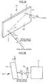
Fig. 3 is a schematic view when a head mounted display of Example 1 is viewed from above. -
Fig. 4 is a schematic view when the head mounted display of Example 1 is viewed from the side. -
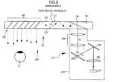
Fig. 5 is a conceptual diagram of an image display apparatus of Example 2. -
Figs. 6A and 6B are conceptual diagrams of an image display apparatus of Example 3. -
Fig. 7 is a conceptual diagram of an image display apparatus of Example 4. -
Figs. 8A and 8B are views schematically showing the propagation of light in a light guide plate that forms an image display apparatus of Example 5, and conceptual diagrams showing an arrangement state of the light guide plate, etc. -
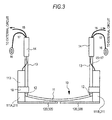
Fig. 9 is a view when a state where an image display apparatus of Example 6 is worn on the head of an observer is obliquely viewed. -
Fig. 10 is a view when the state where the image display apparatus of Example 6 is worn on the head of an observer is viewed from the front. -
Fig. 11 is a view when the state where the image display apparatus of Example 6 is worn on the head of an observer is viewed from the side. -
Fig. 12 is a view when the state where the image display apparatus of Example 6 is worn on the head of an observer is viewed from above. -
Fig. 13 is the schematic view when a head mounted display in the related art is viewed from the side. -
Figs. 14A and 14B are views schematically showing the propagation of light in a light guide plate that forms the image display apparatus in the related art, and conceptual diagrams showing an arrangement state of a light guide plate, etc. that forms an image display apparatus in the related art. - Hereinafter, although the invention will be described on the basis of embodiments with reference to the drawings, the invention is not limited to the embodiments, and various numeric values and materials in the embodiments are illustrative. Description will be given in the following order.
- 1. Overall description relating to image display apparatus and head mounted display of the invention
- 2. Example 1 (image display apparatus according to one embodiment of the invention, and head mounted display according to first embodiment of the invention
- 3. Example 2 (modification of Example 1)
- 4. Example 3 (another modification of Example 1)
- 5. Example 4 (another modification of Example 1)
- 6. Example 5 (another modification of Example 1)
- 7. Example 6 (head mounted display according to second embodiment of the invention), and others
- A head mounted display according to the first embodiment of the invention can be configured so that an image display apparatus is pivotally attached to a frame, with a virtual straight line connecting the centers of two eyeballs of an observer who observes the image display apparatus as a pivot axis. The head mounted display according to the first embodiment of the invention having this configuration, or a head mounted display according to the second embodiment of the invention can be configured so that at least one of the image forming device, the optical system, and the optical device is pivotally attached to the frame. Further, in the head mounted display according to the second embodiment of the invention including such a configuration, when an observer views a horizontally located object (for example, a horizontal direction, an object at an infinite distance, a horizon, or a horizontal line), a depression angle can be formed by the central light beam that is emitted from the optical device and enter the eyes of the observer. For example, 5 degrees to 45 degrees can be exemplified as the depression angle with respect to the horizontal plane.
- In the image display apparatus according to the embodiment of the invention, and an image display apparatus that forms the head mounted display according to the first embodiment of the invention including the above preferable configuration (hereinafter, these are generically and simply referred to as the "image display apparatuses according to the embodiment of the invention"), it is preferable from the viewpoint of ease of handling, setting, and attachment of the image display apparatus that the central light beam be included in the YZ plane.
- In the image display apparatuses according to the first embodiment of the invention including the above preferable embodiment, the optical axis of the optical system is included in the YZ plane and intersects the XY plane at angles other than 0 degree. Alternatively, the image display apparatuses can be configured so that the optical axis of the optical system is parallel to the YZ plane, is parallel to the XY plane, and passes through a position shifted from the center of the image forming device.
- Further, in the head mounted display according to the first embodiment of the invention including the above preferable embodiment and configuration, the head mounted display can be configured so that, assuming that the XY plane coincides with the horizontal plane, the angle θ at which the central light beam CL intersects the XY plane is an elevation angle. That is, the central light beam impinges on the XY plane toward the XY plane from below the XY plane. In this case, it is preferable that the XY plane intersects the vertical plane at angles other than 0 degree, and it is also preferable that the XY plane intersects the vertical plane at an angle θ. In addition, although the maximum value of θ is not limited, the maximum value can be 5 degrees. Here, the horizontal plane is a plane including a line of sight ("a horizontal line of sight of an observer") when the observer views a horizontally located object (for example, a horizontal direction, an object at an infinite distance, a horizon, or a horizontal line), and including two eyes of the observer which are horizontally located. The vertical plane is a plane that is perpendicular to the horizontal plane and includes two eyes of a horizontally located observer.
- Alternatively, in the head mounted display according to the first or second embodiment of the invention, when an observer views a horizontally located object (for example, a horizontal direction, an object at an infinite distance, a horizon, or a horizontal line), a depression angle can be formed by the central light beam that is emitted from the optical device and enters the eyes of the observer. For example, 5 degrees to 45 degrees can be exemplified as the depression angle with respect to the horizontal plane.
- In the image display apparatus according to the first embodiment of the invention including the preferable embodiment and configuration described above, and an image display apparatus that forms the head mounted display according to the second embodiment of the invention (hereinafter, these are generically and simply referred to as the "image display apparatuses according to the embodiment of the invention"), the optical device includes:
- (a) a light guide plate from which incident light is emitted after the light propagates in the light guide plate by total reflection;
- (b) a first deflecting member that deflects the light incident on the light guide plate so that the light incident on the light guide plate is totally reflected in the light guide plate; and
- (c) a second deflecting member that deflects the light, which propagates in the light guide plate by total reflection, multiple times so as to emit the light, which propagates in the light guide plate by total reflection, from the light guide plate.
- Here, the central point of the first deflecting member is an optical device center point. The term "total reflection" refers to total internal reflection or total reflection in the light guide plate. This also applies to the following.
- Here, the first deflecting member can reflect the light incident on the light guide plate, and the second deflecting member can transmit and reflect the light, which propagates in the light guide plate by total reflection, multiple times. In this case, the first deflecting member can function as a reflecting mirror, and the second deflecting member can function as a semi-transmissive mirror.
- In this configuration, the first deflecting member can be formed by, for example, a light reflective film (a kind of mirror) made of metal including an alloy and configured to reflect the light incident on the light guide plate, or a diffraction grating (e.g., a hologram diffraction grating film) for diffracting the light incident on the light guide plate. The second deflecting member can be formed by a multilayer laminated structure in which multiple dielectric laminated films are laminated, a half mirror, a polarizing beam splitter, or a hologram diffraction grating film. Although the first deflecting member and the second deflecting member are disposed (incorporated) in the light guide plate, the first deflecting member reflects or diffracts parallel light incident on the light guide plate so that the incident parallel light is totally reflected in the light guide plate. On the other hand, the second deflecting member reflects or diffracts the parallel light, which propagates in the light guide plate by total reflection, multiple times, and emits the parallel light from the light guide plate.
- Alternatively, the first deflecting member can diffract the light incident on the light guide plate, and the second deflecting member can diffract the light, which propagates in the light guide plate by total reflection, multiple times. In this case, the first deflecting member and the second deflecting member each can be formed by a diffraction grating element. Further, the diffraction grating element can be formed by a reflective diffraction grating element or a transmissive diffraction grating element. Alternatively, one of the diffraction grating elements can be formed by a reflective diffraction grating element, and the other diffraction grating element can be formed by a transmissive diffraction grating element. An example of the reflective diffraction grating element can include a reflective volume hologram diffraction grating. For convenience, the first deflecting member formed by a reflective volume hologram diffraction grating is sometimes referred to as a "first diffraction grating member", and the second deflecting member formed by a reflective volume hologram diffraction grating is sometimes referred to as a "second diffraction grating member".
- When an image display in color is performed by the image display apparatuses according to the embodiment of the invention, in order to diffract or reflect a P-number of (e.g., three corresponding to red, green, and blue) types of light beams having a P-number of different wavelength bands (or wavelengths), in the first diffraction grating member or the second diffraction grating member, a P-number of diffraction grating layers, each formed by a reflective volume hologram diffraction grating, can be laminated. Each diffraction grating layer is formed with interference fringes corresponding to one wavelength band (or wavelength). Alternatively, in order to diffract or reflect a P-number of types of light beams having a P-number of different wavelength bands (or wavelengths), the first diffraction grating member or the second diffraction grating member can be formed by one diffraction grating layer that is provided with a P-number of types of interference fringes. Alternatively, for example, the angle of view can be divided into three parts, and the first diffraction grating member or the second diffraction grating member can be formed by laminating diffraction grating layers corresponding to the parts of the angle of view. By adopting these structures, it is possible to increase the diffraction efficiency and acceptable diffraction angle and to optimize the diffraction angle when the light beams having the wavelength bands (or wavelengths) are diffracted or reflected by the first diffraction grating member or the second diffraction grating member.
- An example of the material that forms the first diffraction grating member and the second diffraction grating member can include a photopolymer material. The material and basic structure of the first diffraction grating member and the second diffraction grating member formed by the reflective volume hologram diffraction gratings may be the same as those of the reflective volume hologram diffraction gratings in the related art. The reflective volume hologram diffraction grating refers to a hologram diffraction grating that diffracts and reflects only +1-order diffracted light. Although the diffraction grating member is formed with interference fringes extending from the inner side to the outer side of the diffraction grating member, a formation method for the interference fringes may be the same as that adopted in the related art. Specifically, for example, the material that forms the diffraction grating member (e.g., a photopolymer material) is irradiated with object light in a first predetermined direction, and is simultaneously irradiated with reference light in a second predetermined direction, whereby the object light and the reference light may form interference fringes in the material that forms the diffraction grating member. By appropriately selecting the first predetermined direction, the second predetermined direction, and the wavelengths of the object light and the reference light, the interference fringes can be arranged at a desired pitch with a desired slant angle on the surfaces of the diffraction grating member. Here, the slant angle of the interference fringes refers to the angle formed between the surfaces of the diffraction grating member (or the diffraction grating layer) and the interference fringes. When the first diffraction grating member and the second diffraction grating member are formed to have a laminated structure in which a P-number of diffraction grating layers, each formed by a reflective volume hologram diffraction grating, are laminated, a P-number of diffraction grating layers are separately formed, and are then laminated (bonded) with, for example, an ultraviolet curing resin adhesive. Alternatively, a P-number of diffraction grating layers may be formed by forming one diffraction grating layer of an adhesive photopolymer material, and then bonding layers of an adhesive photopolymer material thereon in order.
- Alternatively, the image display apparatuses according to the embodiment of the invention can be embodied so that the optical device is formed by a semi-transmissive mirror that the light emitted from the image forming device enters and from which the light is emitted toward the eyes of an observer. The light emitted from the image forming device can enter the semi-transmissive mirror after propagating in the air, or after propagating in a transparent member such as a glass plate or a plastic plate (specifically, a member formed of a material similar to a material that forms the light guide plate, that will be described below). The semi-transmissive mirror may be attached to the image forming device via the transparent member or via a member different from the transparent member.
- The image display apparatuses according to the embodiment of the invention including the preferable embodiments and configurations described above can be embodied so that the image forming device has a plurality of pixels arrayed in a two-dimensional matrix. For convenience, the image forming apparatus having this configuration is referred to as an image forming device having a first configuration.
- In the image forming device having the first structure, for example, the image forming device can be formed by an image forming device including a reflective spatial light modulator and a light source, an image forming device including a transmissive spatial light modulator and a light source, or an image forming device including a light emitting element such as an organic EL (Electro Luminescent) element, an inorganic EL element, or a light emitting diode (LED). Especially, it is preferable that the image forming device includes a reflective spatial light modulator and a light source. For example, the spatial light modulator can be formed by a light valve, a transmissive or reflective liquid crystal display such as an LCOS (Liquid Crystal On Silicon), or a digital micromirror device (DMD), and the light source can be formed by a light emitting element. Further, the reflective spatial light modulator can include a liquid crystal display and a polarizing beam splitter that reflects and guides part of the light from the light source to the liquid crystal display and transmits and guides part of the light reflected by the liquid crystal display to an optical system. The light emitting element that forms the light source can include, for example, a red light emitting element, a green light emitting element, a blue light emitting element, and a white light emitting element, or white light may be obtained by performing color mixture and luminance equalization for the red light, green light, and blue light emitted from the red light emitting element, the green light emitting element, and the blue light emitting element using light valves. The light emitting element can be formed by a semiconductor laser element, a solid-state laser, or an LED. The number of pixels may be determined according to the specifications of the image display apparatus. For example, a concrete number of pixels can be 320×240, 432×240, 640×480, 1024×768, or 1920×1080.
- Alternatively, in the image display apparatuses according to the embodiment of the invention including the preferable embodiments and configurations described above, the image forming device can include a light source, and a scanning member that scans the parallel light emitted from the light source. For convenience, the image forming apparatus having this structure is referred to as "an image forming device having a second configuration".
- The light source in the image forming device having the second structure can include a light emitting element as a light source, more specifically, a red light emitting element, a green light emitting element, a blue light emitting element, and a white light emitting element, or white light may be obtained by performing color mixture and luminance equalization for the red light, green light, and blue light emitted from the red light emitting element, the green light emitting element, and the blue light emitting element using light valves. The light emitting element can be formed by a semiconductor laser element, a solid-state laser, or an LED. The number of pixels (virtual pixels) in the image forming device having the second structure can also be determined according to the specifications of the image display apparatus. For example, a concrete number of pixels (virtual pixels) is 320×240, 432×240, 640×480, 1024×768, or 1920×1080. When an image display in color is performed, and the light source includes a red light emitting element, a green light emitting element, and a blue light emitting element, for example, it is preferable to perform color synthesis using a crossed prism. The scanning member can be formed by a MEMS (Micro Electro Mechanical system) having a micromirror rotatable in the two-dimensional direction, or a galvanometer mirror, which scans light emitted from the light source horizontally and vertically.
- In the image forming device having a first configuration or the image forming device having a second configuration, the light converted into a plurality of parallel light beams by an optical system (an optical system which converts emitted light into parallel light beams: may be referred to as a "parallel light emitting optical system", and specifically, for example, a collimating optical system or a relay optical system) is caused to enter the light guide plate. The reason why the light beams are to be parallel light beams is based on the fact that it is necessary to store the light wave surface information when such light beams have entered the light guide plate even after the light beams have been emitted from the light guide plate via the first deflecting member and the second deflecting member. In order to generate a plurality of parallel light beams, for example, an optical emitting portion of the image forming device may be located at a place (position) corresponding to the focal length of the parallel light emitting optical system. The parallel light emitting optical system functions to convert positional information of pixels into angular information in the optical system of the optical device. For example, the parallel light emitting optical system can be formed by an optical system which has a positive optical power as a whole and which includes a convex lens, a concave lens, an adjustable surface prism, or a hologram lens alone or a combination of these. A light-shielding member having an opening is arranged between the parallel light emitting optical system and the light guide plate so that the light that is not desired is prevented from being emitted from the parallel light emitting optical system and entering the light guide plate.
- The light guide plate has two parallel surfaces (first and second surfaces) extending parallel to the axis (X-axis) of the light guide plate. Assuming that a surface of the light guide plate on which light is incident is an incident surface and a surface of the light guide plate from which light is emitted is an exit surface, both the incident surface and the exit surface may be defined by the first surface, or the incident surface may be defined by the first surface and the exit surface may be defined by the second surface. For example, the light guide plate can be formed of a glass material including optical glass such as quartz glass or BK7, or a plastic material (e.g., PMMA, polycarbonate resin, acrylic resin, amorphous polypropylene resin, or styrene resin including AS resin). The light guide plate is not limited to a flat plate, and may be curved.
- By the image display apparatus according to the embodiment of the invention, for example, a head mounted display can be constructed, the reduction in weight and size of an apparatus can be achieved, the discomfort when the apparatus is mounted can be significantly alleviated, and the manufacture cost can be cut down.
- In the head mounted display according to the first and second embodiments of the invention including the preferable embodiments and configurations described above, the frame can include a front portion to be arranged at the front of an observer; and two temple portions pivotally attached to opposite ends of the front portion via hinges. An end cover portion is attached to a tip portion of each temple portion. Although the image display apparatus is attached to the frame, specifically, the image forming device may be attached to, for example, the temple portion.
- In the head mounted display according to the first or second embodiment of the invention including various kinds of configurations and embodiments described above a nose pad can be attached. That is, when an observer views the whole head mounted display of the embodiment of the invention, the assembly of the frame and the nose pad has almost the same structure as normal eyeglasses except that there is no rim. The material that forms the frame can be the same material as the materials which form normal eyeglasses, such as metal, an alloy, or plastic, and combinations thereof. The nose pad can also have well-known configuration and structure.
- In the head mounted display according to the first or second embodiment of the invention, it is desirable from the viewpoints of design or ease of mounting that a wiring line (a signal line, a power line, etc.) that extends from one or two image forming devices extends to the outside from a tip portion of an end cover portion via a temple portion and the inside of the end cover portion, and is connected to an external circuit (a control circuit). Further, it can be embodied so that each image forming device includes a headphone portion, and a wiring line for the headphone portion from each image forming device extends to the headphone portion via the temple portion and the inside of the end cover portion from the tip portion of the end cover portion. The headphone portion can include, for example, an inner ear type headphone portion and a canal type headphone portion. More specifically, it is preferable that the wiring line for the headphone portion extends to the headphone portion from the tip portion of the end cover portion so as to wrap around behind the auricle (external ear).
- The head mounted display according to the first or second embodiment of the invention can be used for, for example, the display of a title of a film; the display of various description in a play, a kabuki, a Noh, a kyogen, an opera, a concert, a ballet, various theaters, an amusement park, an art museum, a tourist resort, a pleasure resort, a sightseeing guide, etc. ; the display of various descriptions or symbols, signs, marks, emblems, designs, etc. in the operation, manipulation, maintenance, disassembling, etc. of various apparatuses; the display of various descriptions or symbols, signs, marks, emblems, designs, etc. concerning persons, objects. etc.; and the display of closed captions.
- Example 1 relates to an image display apparatus according to the embodiment of the invention, and a head mounted display according to a first embodiment of the invention. A conceptual diagram of the image display apparatus of Example 1 is shown in
Fig. 1 , the propagation of light in a light guide plate that forms the image display apparatus of Example 1 is schematically shown inFig. 2A , and a conceptual diagram showing an arrangement state of the light guide plate, etc. that forms the image display apparatus of Example 1 is shown inFig. 2B . Further, a schematic view when the head mounted display of Example 1 is viewed from above is shown inFig. 3 , and a schematic view when the head mounted display is viewed from the side is shown inFig. 4 . - In Example 1 or Examples 2 to 6 that will be described below, an
image display apparatus - (A) an
image forming device - (B) an optical system (parallel light emitting optical system) 112 or 254 that converts light emitted from the
image forming device - (C) an
optical device optical system - Further, a head mounted display of Example 1 or Examples 2 to 6 that will be described below includes
- (a) a
frame 10 shaped like glasses to be worn on the head of an observer, and - (b) the
image display apparatus frame 10. In addition, although a both-eyes type display including two image display apparatuses has specifically been adopted as the head mounted display of the embodiment, a one-eye type display including one image display apparatus may be adopted. Theimage forming device - In Example 1 or Examples 2 to 6 that will be described below, when the point where a central light beam CL that is emitted from the center of the
image forming device optical system optical device optical device optical device - In Example 1, or Examples 2 to 4, and 6 that will be described below, the optical axis of the
optical system Figs. 2A and 2B ). - In the head mounted display of Example 1, or Examples 2 to 6 that will be described below, assuming that the XY plane coincides with the horizontal plane, the angle θ at which the central light beam CL intersects the XY plane is an elevation angle. That is, the central light beam CL impinges on the XY plane toward the XY plane from below the XY plane. The XY plane intersects a vertical plane at angles other than 0 degree, specifically, an angle θ.
- In Example 1, θ=5 degrees. More specifically, in such a configuration, the central light beam CL (shown by a dotted line in
Fig. 4 ) is included in the horizontal plane. Theoptical device optical device Fig. 4 ) emitted from theoptical device optical device optical device Fig. 2A , orFig. 8A that will be described below, a point where the central light beam CL' is emitted from theoptical device image forming device optical device - In Example 1 or Examples 2 to 6 that will be described below, the
optical device - (a) a
light guide plate - (b) a
first deflecting member light guide plate light guide plate light guide plate - (c) a
second deflecting member light guide plate light guide plate light guide plate member optical device 120 to 320 is a see-through type (semi-transmissive). - Here, in Example 1, the first deflecting
member 130 and thesecond deflecting member 140 are disposed in thelight guide plate 121. Thefirst deflecting member 130 reflects light incident on thelight guide plate 121, and thesecond deflecting member 140 transmits and reflects the light, which propagates in thelight guide plate 121 by total reflection, multiple times. That is, the first deflectingmember 130 functions as a reflecting mirror, and thesecond deflecting member 140 functions as a semi-transmissive mirror. More specifically, the first deflectingmember 130 provided in thelight guide plate 121 is formed by a light reflective film (a kind of mirror) made of aluminum and configured to reflect light incident on thelight guide plate 121. On the other hand, thesecond deflecting member 140 provided in thelight guide plate 121 is formed by a multilayer laminated structure in which multiple dielectric laminated films are laminated. The dielectric laminated films include, for example, a TiO2 film made of a high dielectric constant material and a SiO2 film made of a low dielectric constant material. The multilayer laminated structure in which multiple dielectric laminated films are laminated is disclosed inJP-T-2005-521099 light guide plate 121 are sandwiched between the dielectric laminated films. Thefirst deflecting member 130 reflects (or diffracts) parallel light incident on thelight guide plate 121 so that the parallel light incident on thelight guide plate 121 is totally reflected in thelight guide plate 121. On the other hand, thesecond deflecting member 140 reflects (or diffracts) the parallel light, which propagates in thelight guide plate 121 by total reflection, multiple times, and emits the parallel light toward theeye 41 of an observer from thelight guide plate 121. - An inclined surface where the first deflecting
member 130 is to be formed is formed in thelight guide plate 121 by cutting out aportion 124 of thelight guide plate 121 in which the first deflectingmember 130 is to be provided, a light reflective film is formed on the inclined surface by vacuum deposition, and thecut portion 124 of thelight guide plate 121 is then bonded to the first deflectingmember 130. Further, a multilayer laminated structure, in which multiple layers made of the same material (e.g., glass) as that of thelight guide plate 121 and multiple dielectric films (for example, formed by vacuum deposition) are laminated, is formed, an inclined surface is formed by cutting out aportion 125 of thelight guide plate 121 where thesecond deflecting member 140 is to be formed, the multilayer laminated structure is bonded to the inclined surface, and the outer side of the light guide plate is shaped by, for example, polishing. Thus, theoptical device 120 in which the first deflectingmember 130 and thesecond deflecting member 140 are provided in thelight guide plate 121 can be obtained. - Here, in Example 1, or Examples 2 to 6 that will be described below, the
light guide plate first surface second surface 123 or 323) extending parallel to a light propagation direction (X-axis) by the total internal reflection of thelight guide plate first surface second surface first surface light guide plate 121 by total reflection, and is then emitted from thefirst surface second surface first surface - In Example 1 or Examples 3 that will be described below, the
image forming device 111 is the image forming device having a first configuration, and has a plurality of pixels arrayed in a two-dimensional matrix. Theimage forming device 111 includes a reflective spatiallight modulator 150 and alight source 153 formed by a light emitting diode for emitting white light. The wholeimage forming device 111 is stored in a housing 113 (shown by a one-dot chain line inFig. 1 ), an opening (not shown) is provided in thehousing 113, and light is emitted through the opening from the optical system (the parallel light emitting optical system or the collimating optical system) 112. The reflective spatiallight modulator 150 includes a liquid crystal display (LCD) 151 formed by an LCOS serving as a light valve, and apolarizing beam splitter 152 that reflects and guides part of the light from thelight source 153 to theliquid crystal display 151 and transmits and guides part of the light reflected by theliquid crystal display 151 to theoptical system 112. Theliquid crystal display 151 includes a plurality of (e.g., 640x480) pixels (liquid crystal cells) arrayed in a two-dimensional matrix. Thepolarizing beam splitter 152 has the same configuration and structure as those of the related art. Unpolarized light emitted from thelight source 153 impinges on thepolarizing beam splitter 152. P-polarized light components pass through thepolarizing beam splitter 152, and are emitted to the outside of the system. On the other hand, S-polarized light components are reflected by thepolarizing beam splitter 152, enter theliquid crystal display 151, are reflected in theliquid crystal display 151, and are then emitted from theliquid crystal display 151. Here, light emitted from pixels for displaying white, of light emitted from theliquid crystal display 151, contains many P-polarized light components, and light emitted from pixels for displaying black contains many S-polarized light components. Therefore, P-polarized light components, of the light that is emitted from theliquid crystal display 151 and impinges on thepolarizing beam splitter 152, pass through thepolarizing beam splitter 152, and are guided to theoptical system 112. On the other hand, S-polarized light components are reflected by thepolarizing beam splitter 152, and return to thelight source 153. Theoptical system 112 is formed by, for example, a convex lens. In order to generate parallel light, the image forming device 111 (concretely, the liquid crystal display 151) is arranged at a place (position) corresponding to the focal length of theoptical system 112. - The
frame 10 is formed by afront portion 11 arranged at the front of an observer, twotemple portions 13 pivotally attached to both ends of thefront portion 11 viahinges 12, and an end cover portion (referred to as a tip cell, an earmuff, and an ear pad) 14 attached to a tip portion of eachtemple portion 13. Further, a nose pad (not shown) is attached to the frame. Further, eachhousing 113 is detachably attached to thetemple portion 13 by the attachingmember 18. Theframe 10 is made of metal or plastic. Thehousing 113 may be attached so that the housing can be attached to or detached from thetemple portion 13 by the attachingmember 18. Eachhousing 113 may be detachably attached to the temple portion of the frame of the eyeglasses that is possessed by an observer who possesses and wears the eyeglasses by the attachingmember 18. - A wiring line (a signal line, a power line, etc.) 15 that extends from one
image forming device 111A extends to the outside from the tip portion of theend cover portion 14 via thetemple portion 13 and the inside of theend cover portion 14. Eachimage forming device headphone portion 16, and awiring line 17 for the headphone portion that extends from eachimage forming device headphone portion 16 via thetemple portion 13 and the inside of theend cover portion 14 from the tip portion of theend cover portion 14. More specifically, thewiring line 17 for the headphone portion extends to theheadphone portion 16 from the tip portion of theend cover portion 14 so as to wrap around behind the auricle (external ear). By adopting such a configuration, a neat head mounted display can be formed without giving the impression that theheadphone portion 16 and thewiring line 17 for the headphone portion is randomly arranged. - In the image display apparatus of Example 1, or the image display apparatus that forms the head mounted display of Example 1, the central light beam CL intersects the XY plane at an angle (θ) other than 0 degree. Here, when the central light beam CL' that is emitted from the optical device and enters the eyes of an observer forms the depression angle θ', the relationship of θ'=2θ is satisfied. On the other hand, in the related art, it is necessary to tilt the whole image display apparatus by the angle θ" when it is intended to obtain the same depression angle. Here, the relationship between θ" and θ is θ"=2θ. Eventually, in the related art, the optical device should be tilted by 2θ with respect to the vertical plane. On the other hand, in Example 1, the optical device has only to be tilted by θ with respect to the vertical plane, and the image forming device has only to be horizontally held. Therefore, there is little limitation to the attachment angle of the image display apparatus when the image display apparatus is attached to the attaching portion of a frame shaped like glasses, and a high degree of freedom in design can be obtained. Further, since the tilt of the optical device with respect to the vertical plane is smaller than that in the related art, a phenomenon that outdoor daylight is reflected by the optical device and enters the eyes of an observer hardly occurs compared to the related art. Therefore, a high-quality image can be displayed.
- Example 2 is a modification of Example 1.
Fig. 5 is a conceptual view of animage display apparatus 200 in a head mounted display according to Example 2. As shown inFig. 5 , animage forming device 211 in Example 2 is formed by an image forming device having a second configuration. That is, the image forming device includes alight source 251, and ascanning member 253 that scans the parallel light emitted from thelight source 251. More specifically, theimage forming device 211 includes: - (a) a
light source 251; - (b) a collimating
optical system 252 that converts light emitted from thelight source 251 into parallel light; - (c) a
scanning member 253 that scans the parallel light emitted from the collimatingoptical system 252; and - (d) a relay
optical system 254 that relays and emits the parallel light scanned by the scanningmember 253. In addition, the wholeimage forming device 211 is stored in a housing 213 (shown by a one-dot chain line inFig. 5 ), an opening (not shown) is provided in thehousing 213, and light is emitted through the opening from the relayoptical system 254. Eachhousing 213 is detachably attached to thetemple portion 13 by the attachingmember 18. - The
light source 251 includes a light emitting element for emitting white light. The light emitted from thelight source 251 enters the collimatingoptical system 252 having a positive optical power as a whole, and is emitted as parallel light. The parallel light is reflected by atotal reflection mirror 256, is horizontally and vertically scanned by the scanningmember 253 formed by an MEMS that can rotate a micromirror in a two-dimensional direction so as to two-dimensionally scan the incident parallel light, and is converted into a kind of two-dimensional image, whereby virtual pixels (the number of pixels can be made the same as that of Example 1) are generated. The light from the virtual pixels passes through the relayoptical system 254 formed by a relay optical system of the related art, and light beams converted into parallel light enter theoptical device 120. - The light beams converted into the parallel light by the relay
optical system 254 enter theoptical device 120, and are guided therein, and emitted therefrom. Since theoptical device 120 has the same configuration and structure as that of the optical device adopted in Example 1, a detailed description thereof is omitted. Further, since the head mounted display of Example 2 has substantially the same configuration and structure as those of the head mounted display of Example 1 except that theimage forming device 211 is different, as described above, a detailed description thereof is omitted. - Example 3 is also a modification of Example 1.
Fig. 6A is a conceptual view of animage display apparatus 300 in a head mounted display according to Example 3.Fig. 6B is an enlarged schematic sectional view of a part of a reflective volume hologram diffraction grating. In Example 3, animage forming device 111 is formed by an image forming device having a first configuration, similarly to Example 1. Anoptical device 320 has the same basic configuration and structure as those of theoptical device 120 of Example 1 except in the configuration and structure of a first deflecting member and a second deflecting member. - In Example 3, the first deflecting member and the second deflecting member are disposed on a surface of the light guide plate 321 (concretely, a
second surface 323 of the light guide plate 321) . The first deflecting member diffracts light incident on thelight guide plate 321, and the second deflecting member diffracts the light, which propagates in thelight guide plate 321 by total reflection, multiple times. Here, each of the first and second deflecting members is formed by a diffraction grating element, specifically, a reflective diffraction grating element, and more specifically, a reflective volume hologram diffraction grating. In the following description, for convenience, the first deflecting member formed by a reflective volume hologram diffraction grating is sometimes referred to as a "firstdiffraction grating member 330", and the second deflecting member formed by a reflective volume hologram diffraction grating is sometimes referred to as a "seconddiffraction grating member 340". - In Example 3, or Example 4 that will be described below, in each of the first
diffraction grating member 330 and the seconddiffraction grating member 340, one diffraction grating layer is laminated. Each diffraction grating layer made of a photopolymer material is formed with interference fringes corresponding to one wavelength band (or wavelength), and the interference fringes are formed by a method in the related art. The interference fringes formed on the diffraction grating layers (diffraction optical elements) linearly extend at a fixed pitch and parallel to the Z-axis direction. The axis of the firstdiffraction grating member 330 and the axis of the seconddiffraction grating member 340 are parallel to the X-axis, and the normal axis is parallel to the Y-axis. -
Fig. 6B is an enlarged schematic partial sectional view of a reflective volume hologram diffraction grating. The reflective volume hologram diffraction grating is formed with interference fringes having a slant angle ϕ. Here, the slant angle ϕ refers to the angle formed between the surface of the reflective volume hologram diffraction grating and the interference fringes. The interference fringes are formed to extend from the inner side to the outer side of the reflective volume hologram diffraction grating. The interference fringes satisfy the Bragg condition. Here, the Bragg condition is to satisfy the following Expression A. In Expression A, m is a positive integer, λ represents the wavelength, d represents the pitch of the grating surface (distance between virtual planes including interference fringes in the normal direction), and Θ represents the supplementary angle of the incidence angle on the interference fringes. When light enters the diffraction grating member at an incidence angle ψ, the supplementary angle Θ, the slant angle ψ, and the incidence angle ψ have the relationship given by Expression B:

- As described above, the first
diffraction grating member 330 is disposed (bonded) on thesecond surface 323 of thelight guide plate 321, and diffracts and reflects parallel light incident on thelight guide plate 321 from thefirst surface 322 so that the parallel light incident on thelight guide plate 321 is totally reflected in thelight guide plate 321. Further, as described above, the seconddiffraction grating member 340 is disposed (bonded) on thesecond surface 323 of thelight guide plate 321, and diffracts and reflects the parallel light, which propagates in thelight guide plate 321 by total reflection, multiple times, and emits the parallel light from thelight guide plate 321 through thefirst surface 322. - The parallel light also propagates in the
light guide plate 321 by total reflection, and is then emitted. In this case, since thelight guide plate 321 is thin and the optical path in thelight guide plate 321 is long, the number of total reflections made until the light beams reach the seconddiffraction grating member 340 varies according to the angle of view. More specifically, the number of reflections of parallel light that is incident at an angle such as to approach the seconddiffraction grating member 340, of parallel light incident on thelight guide plate 321, is smaller than the number of reflections of parallel light that is incident on thelight guide plate 321 at an angle such as to get away from the seconddiffraction grating member 340. This is because the parallel light, which is diffracted and reflected by the firstdiffraction grating member 330 and is incident on thelight guide plate 321 at the angle such as to approach the seconddiffraction grating member 340, forms a smaller angle to the normal angle at thelight guide plate 321 when the light propagating in thelight guide plate 321 impinges on the inner surface of thelight guide plate 321, than the parallel light that is incident on thelight guide plate 321 at the angle in the opposite direction. The shape of the interference fringes formed in the seconddiffraction grating member 340 and the shape of the interference fringes formed in the firstdiffraction grating member 330 are symmetrical with respect to an imaginary plane perpendicular to the axis of thelight guide plate 321. - The
light guide plate 321 in Example 4 that will be described below has the same configuration and structure as those of thelight guide plate 321 described above. - Since the head mounted display of Example 3 has substantially the same configuration and structure as those of the head mounted display of Example 1 except that the
optical device 320 is different, as described above, a detailed description thereof is omitted. - Example 4 is a modification of Example 3.
Fig. 7 is a conceptual view of an image display apparatus in a head mounted display according to Example 4. In animage display apparatus 400 of Example 4, alight source 251, a collimatingoptical system 252, ascanning member 253, a parallel light emitting optical system (a relay optical system 254), etc. have the same configuration and structure (the image forming device having a second configuration) as those adopted in Example 2. Further, anoptical device 320 has the same configuration and structure as those of theoptical device 320 in Example 3. Since the head mounted display of Example 4 has substantially the same configuration and structure as those of the head mounted display of Example 1 except the above-described differences, a detailed description thereof is omitted. - Example 5 is a modification of Example 1. The propagation of light in a light guide plate that forms the image display apparatus of Example 5 is schematically shown in
Fig. 8A , and a conceptual diagram showing an arrangement state of a light guide plate, etc. that forms the image display apparatus of Example 5 is shown inFig. 8B . Here, in Example 5, the optical axis of the optical system (the parallel light emitting optical system or the collimating optical system) 112 is parallel to the YZ plane, is parallel to the XY plane, and passes through a position shifted from the center of theimage forming device 111. By adopting such a configuration, the central light beam CL is included in the YZ plane, and intersects the XY plane at an elevation angle θ. - Example 6 is a modification of Examples 1 to 5, and relates to a head mounted display according to a second embodiment of the invention. A view when a state where the image display apparatus of Example 6 is worn on the head of an observer is obliquely viewed is shown in
Fig. 9 , a view when the image display apparatus is viewed from the front is shown inFig. 10 , a view when the image display apparatus is viewed from the side is shown inFig. 11 , and a view when the image display apparatus is viewed from above is shown inFig. 12 . Although these drawings show that the image display apparatus is worn on the head of an observer, they shows a state before the image display apparatus pivots downward with respect to the frame, with a virtual straight line connecting the centers of two eyeballs of the observer who observes the image display apparatus as a pivot axis. - Similarly to those described in Examples 1 to 5, the head mounted display of Example 6 includes (a) a frame shaped like
glasses 50 to be worn on the head of an observer, and
(b) animage display apparatus frame 50, and theimage display apparatus - (A) an
image forming device - (B) an optical system (a parallel light emitting optical system) 112 or 254 which converts the light emitted from the
image forming device - (C) an
optical device optical system - The
image display apparatus frame 50, with a virtual straight line connecting the centers of two eyeballs of the observer who observes theimage display apparatus image forming device optical system optical device 120 or 320 (more specifically, theimage forming device optical system optical device frame 50. In the head mounted display of Example 6, when an observer views a horizontally located object, a central light beam that is emitted from the optical device and enters the eyes of the observer forms a depression angle, and the depression angle with respect to the horizontal plane is, for example, 5 degrees to 45 degrees. - In the head mounted display of Example 6, the
frame 50 is formed by afront portion 51 arranged at the front of an observer, and twotemple portions 53 attached to both ends of thefront portion 51 in a fixed state. A tip portion of eachtemple portion 53 is formed by a U-shaped member. In the following description, a tip portion of thetemple portion 53 equivalent to a U-shaped upper crossbar is referred to as a "first member 53A", a tip portion of thetemple portion 53 equivalent to a U-shaped lower crossbar is referred to as a "second member 53B", and a tip portion of thetemple portion 53 equivalent to a U-shaped longitudinal bar is referred to as a "third member 53C". Thesecond member 53B is attached to both ends of thefront portion 51 in a fixed state. An arm portion (handle portion) 53D further extends toward anend cover portion 54 from thethird member 53C. Twoend cover portions 54 are connected together by a holdingband 55 to prevent the head mounted display from shifting when the head mounted display is worn on a head. Such a mounting band can be incorporated even in Examples 1 to 5. - The
image forming device first member 53A and thesecond member 53B, and is surrounded by thefirst member 53A, thesecond member 53B, andthird member 53C. Specifically, a recessed portion (not shown) is provided in theimage forming device first member 53A, and the face of thefirst member 53A that faces theimage forming device image forming device second member 53B is provided with a threaded hole portion (not shown), and thesecond member 53B that faces theimage forming device image forming device temple portion 53 by fitting the recessed portion provided in theimage forming device first member 53A, passing a screw (the head of ascrew 56 is shown inFig. 11 only) through the through hole provided in thesecond member 53B, and screwing thescrew 56 into the hole portion provided in theimage forming device image forming device temple portion 53, it is preferable that a push spring be inserted into a shank of thescrew 56 between the head of thescrew 56 and theimage forming device first member 53A and thescrew 56, and a virtual straight line connecting the centers of two eyeballs of an observer are located on the pivot axis RX. Theimage display apparatus frame 50, with the virtual straight line connecting the centers of two eyeballs of the observer as the pivot axis RX. In addition, the attaching mechanism and attaching method of theimage display apparatus first member 53A and thescrew 56, and the virtual straight line connecting the centers of two eyeballs of an observer are slightly shifted from each other, i.e., when the distance between the virtual straight line connecting the centers of two eyeballs of the observer, and the pivot axis RX is a maximum of 6.5 mm, there is no case where an image emitted from theimage display apparatus image display apparatus frame 50, with a virtual straight line connecting the centers of two eyeballs of an observer who observes an image display apparatus as a pivot axis. - Since the image display apparatus and the light guide plate in Example 6 can have the same configuration and structure as the image display apparatus and the light guide plate which are described in Examples 1 to 5, a detailed description thereof is omitted.
- Since the
image display apparatus frame 50, with a virtual straight line connecting the centers of two eyeballs of the observer who observes the image display apparatus as a pivot axis RX, even when theimage display apparatus image display apparatus image display apparatus - In addition, even when it is unnecessary to display a display image while being shifted to a position above or below a horizontal line of sight of an observer, when it is necessary to pivot the image display apparatus to move the image display apparatus in the vertical direction, thereby optimizing the position of the image display apparatus, the mechanism, configuration, and structure which allows the central light beam to intersect the XY plane at angles (θ) other than 0 degree as described in Examples 1 to 5 are unnecessary. The image display apparatus has only to be pivotally attached to the frame, with a virtual straight line connecting the centers of two eyeballs of an observer who observes the image display apparatus as a pivot axis.
- Although the invention has been described above on the basis of the preferable embodiments, the invention is not limited to these embodiments. The configuration and structure of the image display apparatus and the head mounted display that have been described in the embodiments are merely illustrative, and can be suitably altered. For example, a surface relief-type hologram (refer to
US Patent Application Publication 2004/0062505A1 ) may be arranged in the light guide plate. Theoptical device 320 of Example 3 or 4, can also be embodied so that the diffraction grating element is formed by a transmissive diffraction grating element, or any one of the first deflecting member and the second deflecting member is formed by a relfective diffraction grating element, and the other is formed by a transmissive diffraction grating element. Alternatively, a relfective blazed diffraction grating element can also be used as the diffraction grating element. - The present application contains subject matter related to those disclosed in Japanese Priority Patent Applications
JP 2009-199567 JP 2009-280133 - It should be understood by those skilled in the art that various modifications, combinations, sub-combinations and alterations may occur depending on design requirements and other factors insofar as they are within the scope of the appended claims or the equivalents thereof.
- Support for the claims and further embodiments are defined in the following itemized list:
- 1. An image display apparatus comprising:
- (A) an image forming device;
- (B) an optical system that converts light emitted from the image forming device into parallel light; and
- (C) an optical device to which the light beams converted into the parallel light by the optical system enter, in which the light beams are guided, and from which the light beams are emitted,
the central light beam intersects the XY plane at angles other than 0 degree. - 2. The image display apparatus according to
item 1, wherein the central light beam is included in the YZ plane. - 3. The image display apparatus according to
item 1 or 2,
wherein the optical axis of the optical system is included in the YZ plane and intersects the XY plane at angles other than 0 degree. - 4. The image display apparatus according to
item 1 or 2,
wherein the optical axis of the optical system is parallel to the YZ plane, is parallel to the XY plane, and passes through a position shifted from the center of the image forming device. - 5. The image display apparatus according to
item 1,
wherein the optical device includes:- (a) a light guide plate from which incident light is emitted after the light propagates in the light guide plate by total reflection;
- (b) a first deflecting means for deflecting the light incident on the light guide plate so that the light incident on the light guide plate is totally reflected in the light guide plate; and
- (c) a second deflecting means for deflecting the light, which propagates in the light guide plate by total reflection, multiple times so as to emit the light, which propagates in the light guide plate by total reflection, from the light guide plate, and wherein the central point of the first deflecting means is the optical device center point.
- 6. A head mounted display comprising:
- (a) a frame shaped like glasses to be worn on the head of an observer; and
- (b) an image display apparatus attached to the frame, the image display apparatus including
- (A) an image forming device;
- (B) an optical system that converts light emitted from the image forming device into parallel light; and
- (C) an optical device to which the light beams converted into the parallel light by the optical system enter, in which the light beams are guided, and from which the light beams are emitted,
the central light beam intersects the XY plane at angles other than 0 degree. - 7. The head mounted display according to item 6,
wherein the image display apparatus is pivotally attached to the frame, with a virtual straight line connecting the centers of two eyeballs of the observer who observes the image display apparatus as a pivot axis. - 8. The head mounted display according to item 7,
wherein at least one of the image forming device, the optical system, and the optical device is pivotally attached to the frame. - 9. The head mounted display according to item 6,
wherein the central light beam is included in the YZ plane. - 10. The head mounted display according to item 6 or 9,
wherein the optical axis of the optical system is included in the YZ plane and intersects the XY plane at angles other than 0 degree. - 11. The head mounted display according to item 6 or 9,
wherein the optical axis of the optical system is parallel to the YZ plane, is parallel to the XY plane, and passes through a position shifted from the center of the image forming device. - 12. The head mounted display according to item 6,
wherein assuming that the XY plane coincides with the horizontal plane, the angle θ at which the central light beam intersects the XY plane is an elevation angle. - 13. The head mounted display according to
item 12,
wherein the XY plane intersects the vertical plane at angles other than 0 degree. - 14. The head mounted display according to
item 13,
wherein the XY plane intersects the vertical plane at an angle θ. - 15. The head mounted display according to any one of
items 12 to 14,
wherein the maximum value of θ is 5 degrees. - 16. The head mounted display according to item 6,
wherein when an observer views a horizontally located object, a central light beam that is emitted from the optical device and enters the eyes of the observer forms a depression angle. - 17. The head mounted display according to item 6,
wherein the frame is formed by a front portion arranged at the front of an observer, and two temple portions pivotally attached to both ends of the front portion via hinges. - 18. A head mounted display comprising:
- (a) a frame shaped like glasses to be worn on the head of an observer; and an image display apparatus attached to the frame, the image display apparatus including
- (A) an image forming device;
- (B) an optical system that converts light emitted from the image forming device into parallel light; and
- (C) an optical device to which the light beams converted into the parallel light by the optical system enter, in which the light beams are guided, and from which the light beams are emitted,
- (a) a frame shaped like glasses to be worn on the head of an observer; and an image display apparatus attached to the frame, the image display apparatus including
- 19. The head mounted display according to
item 18,
wherein at least one of the image forming device, the optical system, and the optical device is pivotally attached to the frame. - 20. The head mounted display according to
item 18,
wherein when an observer views a horizontally located object, a central light beam that is emitted from the optical device and enters the eyes of the observer forms a depression angle.
Claims (15)
- An image display apparatus comprising:an image forming device configured to emit light; andan optical device configured to receive, guide, and output the emitted light, whereina point where a central light beam to be emitted from a light-emission surface of the optical device towards an eye is defined as an optical device center point,
an axis that passes through the optical device center point and is parallel to the light-emission surface is defined as an X-axis,
an axis that passes through the optical device center point and is normal to the light-emission surface is defined as a Y-axis,
an axis orthogonal to the X-axis and the Y-axis is defined as a Z-axis;
the X-axis and the Y-axis form an XY plane, and the Y-axis and the Z-axis form a YZ plane, and
the central light beam intersects the XY plane at an angle other than 0 degree. - The image display apparatus according to Claim 1,
wherein the central light beam is included in the YZ plane. - The image display apparatus according to Claim 1 or 2, wherein the optical device comprises an optical system that converts light emitted from the image forming device into parallel light, which is then guided and output from the optical device.
- The image display apparatus according to Claim 3,
wherein an optical axis of the optical system is included in a plane parallel to the YZ plane and intersects the XY plane at angles other than 0 degree. - The image display apparatus according to Claim 3,
wherein the optical axis of the optical system is parallel to the YZ plane, is parallel to the XY plane, and passes through a position shifted from the center of the image forming device. - The image display apparatus according to Claim 1,
wherein the optical device includes:a light guide plate from which incident light is emitted after the light propagates in the light guide plate by total reflection;a first deflecting means for deflecting the light incident on the light guide plate so that the light incident on the light guide plate is totally reflected in the light guide plate; anda second deflecting means for deflecting the light, which propagates in the light guide plate by total reflection, multiple times so as to emit the light, which propagates in the light guide plate by total reflection, from the light guide plate, andwherein the central point of the first deflecting means is the optical device center point. - A head mounted display comprising:a frame shaped like glasses to be worn on the head of an observer; andthe image display apparatus according to any one of claims 1 to 5.
- The head mounted display according to Claim 7,
wherein the image display apparatus is pivotally attached to the frame, with a virtual straight line connecting the centers of two eyeballs of the observer who observes the image display apparatus as a pivot axis. - The head mounted display according to Claim 8,
wherein at least one of the image forming device and the optical device is pivotally attached to the frame. - The head mounted display according to Claim 7,
wherein assuming that the XY plane coincides with a horizontal plane, the angle θ at which the central light beam intersects the XY plane is an elevation angle. - The head mounted display according to Claim 10,
wherein the XY plane intersects a vertical plane at angles other than 0 degree. - The head mounted display according to Claim 11,
wherein the XY plane intersects the vertical plane at an angle θ. - The head mounted display according to any one of Claims 10 to 12,
wherein the maximum value of θ is 5 degrees. - The head mounted display according to Claim 7,
wherein when an observer views a horizontally located object, a central light beam that is emitted from the optical device and enters the eyes of the observer forms a depression angle. - The head mounted display according to Claim 7,
wherein the frame is formed by a front portion arranged at the front of an observer, and two temple portions pivotally attached to both ends of the front portion via hinges.
Applications Claiming Priority (3)
| Application Number | Priority Date | Filing Date | Title |
|---|---|---|---|
| JP2009199567 | 2009-08-31 | ||
| JP2009280133A JP5316391B2 (en) | 2009-08-31 | 2009-12-10 | Image display device and head-mounted display |
| EP10008392.2A EP2290428B1 (en) | 2009-08-31 | 2010-08-11 | Image display apparatus and head mounted display |
Related Parent Applications (2)
| Application Number | Title | Priority Date | Filing Date |
|---|---|---|---|
| EP10008392.2A Division EP2290428B1 (en) | 2009-08-31 | 2010-08-11 | Image display apparatus and head mounted display |
| EP10008392.2A Division-Into EP2290428B1 (en) | 2009-08-31 | 2010-08-11 | Image display apparatus and head mounted display |
Publications (3)
| Publication Number | Publication Date |
|---|---|
| EP3128358A2 true EP3128358A2 (en) | 2017-02-08 |
| EP3128358A3 EP3128358A3 (en) | 2017-04-12 |
| EP3128358B1 EP3128358B1 (en) | 2020-01-01 |
Family
ID=42964538
Family Applications (2)
| Application Number | Title | Priority Date | Filing Date |
|---|---|---|---|
| EP10008392.2A Active EP2290428B1 (en) | 2009-08-31 | 2010-08-11 | Image display apparatus and head mounted display |
| EP16188898.7A Active EP3128358B1 (en) | 2009-08-31 | 2010-08-11 | Image display apparatus and head mounted display |
Family Applications Before (1)
| Application Number | Title | Priority Date | Filing Date |
|---|---|---|---|
| EP10008392.2A Active EP2290428B1 (en) | 2009-08-31 | 2010-08-11 | Image display apparatus and head mounted display |
Country Status (5)
| Country | Link |
|---|---|
| US (4) | US8570244B2 (en) |
| EP (2) | EP2290428B1 (en) |
| JP (1) | JP5316391B2 (en) |
| KR (1) | KR101722783B1 (en) |
| CN (1) | CN102004315B (en) |
Families Citing this family (128)
| Publication number | Priority date | Publication date | Assignee | Title |
|---|---|---|---|---|
| JP5316391B2 (en) * | 2009-08-31 | 2013-10-16 | ソニー株式会社 | Image display device and head-mounted display |
| KR100998484B1 (en) * | 2010-07-07 | 2010-12-06 | 레이져라이팅(주) | Apparatus for processing light guide plate with laser having uniform length of travel path of laser beam |
| US8743463B2 (en) * | 2011-02-04 | 2014-06-03 | Seiko Epson Corporation | Virtual image display |
| CN102918444B (en) * | 2011-03-25 | 2015-12-23 | 松下电器产业株式会社 | Display device |
| JP5879886B2 (en) * | 2011-10-03 | 2016-03-08 | セイコーエプソン株式会社 | Virtual image display device and manufacturing method thereof |
| EP4036862A1 (en) * | 2011-11-23 | 2022-08-03 | Magic Leap, Inc. | Three dimensional virtual and augmented reality display system |
| US9223138B2 (en) | 2011-12-23 | 2015-12-29 | Microsoft Technology Licensing, Llc | Pixel opacity for augmented reality |
| US8917453B2 (en) | 2011-12-23 | 2014-12-23 | Microsoft Corporation | Reflective array waveguide |
| US8638498B2 (en) | 2012-01-04 | 2014-01-28 | David D. Bohn | Eyebox adjustment for interpupillary distance |
| US8384999B1 (en) | 2012-01-09 | 2013-02-26 | Cerr Limited | Optical modules |
| US9606586B2 (en) | 2012-01-23 | 2017-03-28 | Microsoft Technology Licensing, Llc | Heat transfer device |
| US8810600B2 (en) | 2012-01-23 | 2014-08-19 | Microsoft Corporation | Wearable display device calibration |
| JP5901321B2 (en) * | 2012-02-06 | 2016-04-06 | オリンパス株式会社 | Image display device |
| US9297996B2 (en) | 2012-02-15 | 2016-03-29 | Microsoft Technology Licensing, Llc | Laser illumination scanning |
| US9726887B2 (en) | 2012-02-15 | 2017-08-08 | Microsoft Technology Licensing, Llc | Imaging structure color conversion |
| US9368546B2 (en) | 2012-02-15 | 2016-06-14 | Microsoft Technology Licensing, Llc | Imaging structure with embedded light sources |
| US9779643B2 (en) | 2012-02-15 | 2017-10-03 | Microsoft Technology Licensing, Llc | Imaging structure emitter configurations |
| JP6035793B2 (en) * | 2012-03-14 | 2016-11-30 | ソニー株式会社 | Image display device and image generation device |
| US9578318B2 (en) | 2012-03-14 | 2017-02-21 | Microsoft Technology Licensing, Llc | Imaging structure emitter calibration |
| US11068049B2 (en) | 2012-03-23 | 2021-07-20 | Microsoft Technology Licensing, Llc | Light guide display and field of view |
| US10191515B2 (en) | 2012-03-28 | 2019-01-29 | Microsoft Technology Licensing, Llc | Mobile device light guide display |
| US9558590B2 (en) | 2012-03-28 | 2017-01-31 | Microsoft Technology Licensing, Llc | Augmented reality light guide display |
| US9717981B2 (en) | 2012-04-05 | 2017-08-01 | Microsoft Technology Licensing, Llc | Augmented reality and physical games |
| US10502876B2 (en) | 2012-05-22 | 2019-12-10 | Microsoft Technology Licensing, Llc | Waveguide optics focus elements |
| JP6028400B2 (en) * | 2012-06-04 | 2016-11-16 | セイコーエプソン株式会社 | Image display device and head mounted display |
| US8989535B2 (en) | 2012-06-04 | 2015-03-24 | Microsoft Technology Licensing, Llc | Multiple waveguide imaging structure |
| FR2998681B1 (en) * | 2012-11-29 | 2015-01-30 | Commissariat Energie Atomique | HIGH HEAD VISITOR WITH IMPROVED VISUALIZATION COMFORT |
| US10192358B2 (en) | 2012-12-20 | 2019-01-29 | Microsoft Technology Licensing, Llc | Auto-stereoscopic augmented reality display |
| KR102097845B1 (en) * | 2013-01-10 | 2020-04-06 | 소니 주식회사 | Image display device, image generating device, and transparent spatial light modulating device |
| GB201304659D0 (en) * | 2013-03-14 | 2013-05-01 | Sec Dep For Business Innovation & Skills The | Display and method of operating a display |
| CN104460002B (en) * | 2013-09-22 | 2017-06-16 | 江苏慧光电子科技有限公司 | It is wearable to look squarely optical system |
| JP6255983B2 (en) * | 2013-12-25 | 2018-01-10 | セイコーエプソン株式会社 | Virtual image display device |
| JP6337465B2 (en) | 2013-12-26 | 2018-06-06 | セイコーエプソン株式会社 | Virtual image display device |
| US9459451B2 (en) * | 2013-12-26 | 2016-10-04 | Microsoft Technology Licensing, Llc | Eye tracking apparatus, method and system |
| EP3100096A1 (en) * | 2014-01-31 | 2016-12-07 | Mack, Corey | Augmented reality eyewear and methods for using same |
| KR102224459B1 (en) * | 2014-02-05 | 2021-03-08 | 엘지이노텍 주식회사 | Geometric Lighting Device and Vehicle Lighting Device Using the Same |
| KR20150095342A (en) * | 2014-02-13 | 2015-08-21 | 삼성전자주식회사 | Head-mount type display apparatus |
| US9563269B2 (en) * | 2014-03-25 | 2017-02-07 | Microsoft Technology Licensing, Llc | Scanning liquid-crystal display backlight |
| US9304235B2 (en) | 2014-07-30 | 2016-04-05 | Microsoft Technology Licensing, Llc | Microfabrication |
| US10678412B2 (en) | 2014-07-31 | 2020-06-09 | Microsoft Technology Licensing, Llc | Dynamic joint dividers for application windows |
| US10592080B2 (en) | 2014-07-31 | 2020-03-17 | Microsoft Technology Licensing, Llc | Assisted presentation of application windows |
| US10254942B2 (en) | 2014-07-31 | 2019-04-09 | Microsoft Technology Licensing, Llc | Adaptive sizing and positioning of application windows |
| US9377623B2 (en) | 2014-08-11 | 2016-06-28 | Microsoft Technology Licensing, Llc | Waveguide eye tracking employing volume Bragg grating |
| US9494799B2 (en) | 2014-09-24 | 2016-11-15 | Microsoft Technology Licensing, Llc | Waveguide eye tracking employing switchable diffraction gratings |
| JP6424552B2 (en) | 2014-10-02 | 2018-11-21 | セイコーエプソン株式会社 | Image display device |
| JP6439453B2 (en) * | 2015-01-09 | 2018-12-19 | セイコーエプソン株式会社 | Image display device and method of manufacturing image display device |
| US9513480B2 (en) | 2015-02-09 | 2016-12-06 | Microsoft Technology Licensing, Llc | Waveguide |
| US10018844B2 (en) | 2015-02-09 | 2018-07-10 | Microsoft Technology Licensing, Llc | Wearable image display system |
| US11086216B2 (en) | 2015-02-09 | 2021-08-10 | Microsoft Technology Licensing, Llc | Generating electronic components |
| US9827209B2 (en) | 2015-02-09 | 2017-11-28 | Microsoft Technology Licensing, Llc | Display system |
| US9429692B1 (en) | 2015-02-09 | 2016-08-30 | Microsoft Technology Licensing, Llc | Optical components |
| US9423360B1 (en) | 2015-02-09 | 2016-08-23 | Microsoft Technology Licensing, Llc | Optical components |
| US10317677B2 (en) | 2015-02-09 | 2019-06-11 | Microsoft Technology Licensing, Llc | Display system |
| US9372347B1 (en) | 2015-02-09 | 2016-06-21 | Microsoft Technology Licensing, Llc | Display system |
| US9535253B2 (en) | 2015-02-09 | 2017-01-03 | Microsoft Technology Licensing, Llc | Display system |
| EP3062142B1 (en) | 2015-02-26 | 2018-10-03 | Nokia Technologies OY | Apparatus for a near-eye display |
| JPWO2016162901A1 (en) | 2015-04-07 | 2018-02-01 | オリンパス株式会社 | Eyeglass type display device |
| TWI547717B (en) * | 2015-05-13 | 2016-09-01 | 華邦電子股份有限公司 | Head-mounted display |
| CN104865809A (en) * | 2015-06-17 | 2015-08-26 | 京东方科技集团股份有限公司 | Display device and displayer |
| US10007115B2 (en) | 2015-08-12 | 2018-06-26 | Daqri, Llc | Placement of a computer generated display with focal plane at finite distance using optical devices and a see-through head-mounted display incorporating the same |
| US20170115489A1 (en) * | 2015-10-26 | 2017-04-27 | Xinda Hu | Head mounted display device with multiple segment display and optics |
| EP3205512B1 (en) | 2016-02-09 | 2018-06-13 | CSEM Centre Suisse d'Electronique et de Microtechnique SA - Recherche et Développement | Optical security device |
| US10649209B2 (en) | 2016-07-08 | 2020-05-12 | Daqri Llc | Optical combiner apparatus |
| US11740777B2 (en) | 2016-09-15 | 2023-08-29 | Circlesx Llc | Multi-dimension information service helmet method and system |
| US11790382B2 (en) | 2016-09-15 | 2023-10-17 | Circlesx Llc | Method to transmit geolocation exchange based markets |
| US11157852B2 (en) | 2016-09-15 | 2021-10-26 | Simpsx Technologies Llc | Tool appliance community objects with price-time priority queues for transformed tool appliance units |
| US11138661B2 (en) | 2016-09-15 | 2021-10-05 | Simpsx Technologies Llc | Agriculture community objects with price-time priority queues for transformed agriculture units |
| US10460520B2 (en) * | 2017-01-13 | 2019-10-29 | Simpsx Technologies Llc | Computer ball device for mixed reality, virtual reality, or augmented reality |
| US11810023B2 (en) | 2018-10-22 | 2023-11-07 | Circlesx Llc | System and method for a transportation or freight capacity exchange for one or more transportation or freight capacity units |
| US11880883B2 (en) | 2016-09-15 | 2024-01-23 | Circlesx Llc | Systems and methods for geolocation portfolio exchanges |
| US20190272589A1 (en) | 2016-09-15 | 2019-09-05 | Erik M. Simpson | Securitization of transportation units |
| US11823090B2 (en) | 2016-09-15 | 2023-11-21 | Circlesx Llc | Transportation and freight and parking and tolling and curb capacity unit IPO method and system |
| US11215466B2 (en) | 2016-09-15 | 2022-01-04 | Circlesx Llc | Route community objects with price-time priority queues for transformed transportation units |
| US11035682B2 (en) | 2016-09-15 | 2021-06-15 | Simpsx Technologies Llc | Navigation routes as community object virtual hub sequences to which users may subscribe |
| US11138827B2 (en) | 2016-09-15 | 2021-10-05 | Simpsx Technologies Llc | Implementations of a computerized business transaction exchange for various users |
| US11861527B2 (en) | 2018-11-07 | 2024-01-02 | Circlesx Llc | Financial swap payment structure method and system on transportation capacity unit assets |
| US20190228351A1 (en) | 2018-01-23 | 2019-07-25 | Erik M. Simpson | Electronic forward market exchange for transportation seats and capacity in transportation spaces and vehicles |
| US10650552B2 (en) | 2016-12-29 | 2020-05-12 | Magic Leap, Inc. | Systems and methods for augmented reality |
| EP4300160A2 (en) | 2016-12-30 | 2024-01-03 | Magic Leap, Inc. | Polychromatic light out-coupling apparatus, near-eye displays comprising the same, and method of out-coupling polychromatic light |
| US10481678B2 (en) | 2017-01-11 | 2019-11-19 | Daqri Llc | Interface-based modeling and design of three dimensional spaces using two dimensional representations |
| CN110573932B (en) | 2017-06-06 | 2022-08-23 | 苹果公司 | Optical system for electronic device with display |
| US10409070B2 (en) | 2017-06-30 | 2019-09-10 | Seiko Epson Corporation | Virtual image display apparatus |
| US10578870B2 (en) | 2017-07-26 | 2020-03-03 | Magic Leap, Inc. | Exit pupil expander |
| CN111512189B (en) | 2017-10-02 | 2023-02-21 | 瑞士Csem电子显微技术研发中心 | Resonant waveguide grating and application thereof |
| US11280937B2 (en) | 2017-12-10 | 2022-03-22 | Magic Leap, Inc. | Anti-reflective coatings on optical waveguides |
| WO2019126331A1 (en) | 2017-12-20 | 2019-06-27 | Magic Leap, Inc. | Insert for augmented reality viewing device |
| CN115493480A (en) | 2018-01-16 | 2022-12-20 | 太平洋灯光全息图公司 | Three-dimensional display method, display screen and system using electromagnetic field calculation |
| US10942355B2 (en) * | 2018-01-22 | 2021-03-09 | Facebook Technologies, Llc | Systems, devices, and methods for tiled multi-monochromatic displays |
| US10802277B2 (en) * | 2018-02-01 | 2020-10-13 | Seiko Epson Corporation | Head-mounted display device |
| US10488666B2 (en) | 2018-02-10 | 2019-11-26 | Daqri, Llc | Optical waveguide devices, methods and systems incorporating same |
| US10755676B2 (en) | 2018-03-15 | 2020-08-25 | Magic Leap, Inc. | Image correction due to deformation of components of a viewing device |
| JP7349445B2 (en) | 2018-04-02 | 2023-09-22 | マジック リープ, インコーポレイテッド | Waveguides with integrated optical elements and methods for making the same |
| JP7128648B2 (en) * | 2018-04-25 | 2022-08-31 | 株式会社日立エルジーデータストレージ | head mounted display |
| WO2019232282A1 (en) | 2018-05-30 | 2019-12-05 | Magic Leap, Inc. | Compact variable focus configurations |
| JP7319303B2 (en) | 2018-05-31 | 2023-08-01 | マジック リープ, インコーポレイテッド | Radar head pose localization |
| CN112400157A (en) | 2018-06-05 | 2021-02-23 | 奇跃公司 | Homography transformation matrix based temperature calibration of viewing systems |
| EP3803545A4 (en) | 2018-06-08 | 2022-01-26 | Magic Leap, Inc. | Augmented reality viewer with automated surface selection placement and content orientation placement |
| JP2020003692A (en) * | 2018-06-29 | 2020-01-09 | ソニー株式会社 | Head-mounted type display |
| US11579441B2 (en) | 2018-07-02 | 2023-02-14 | Magic Leap, Inc. | Pixel intensity modulation using modifying gain values |
| US11856479B2 (en) | 2018-07-03 | 2023-12-26 | Magic Leap, Inc. | Systems and methods for virtual and augmented reality along a route with markers |
| WO2020010226A1 (en) | 2018-07-03 | 2020-01-09 | Magic Leap, Inc. | Systems and methods for virtual and augmented reality |
| JP7426982B2 (en) | 2018-07-24 | 2024-02-02 | マジック リープ, インコーポレイテッド | Temperature-dependent calibration of movement sensing devices |
| WO2020023543A1 (en) | 2018-07-24 | 2020-01-30 | Magic Leap, Inc. | Viewing device with dust seal integration |
| CN112740665A (en) | 2018-08-02 | 2021-04-30 | 奇跃公司 | Observation system for interpupillary distance compensation based on head movement |
| CN116820239A (en) | 2018-08-03 | 2023-09-29 | 奇跃公司 | Fusion gesture based drift correction of fusion gestures for totem in a user interaction system |
| JP6958530B2 (en) * | 2018-10-10 | 2021-11-02 | セイコーエプソン株式会社 | Optical module and head-mounted display |
| US10608409B1 (en) * | 2018-10-19 | 2020-03-31 | Microsoft Technology Licensing, Llc | Calibration of laser power monitor in an imaging system of a wearable head mounted display |
| JP2020071305A (en) * | 2018-10-30 | 2020-05-07 | セイコーエプソン株式会社 | Head-mounted display device |
| US10914949B2 (en) | 2018-11-16 | 2021-02-09 | Magic Leap, Inc. | Image size triggered clarification to maintain image sharpness |
| US11125993B2 (en) | 2018-12-10 | 2021-09-21 | Facebook Technologies, Llc | Optical hyperfocal reflective systems and methods, and augmented reality and/or virtual reality displays incorporating same |
| KR20210100175A (en) | 2018-12-10 | 2021-08-13 | 페이스북 테크놀로지스, 엘엘씨 | Adaptive Viewport for Hyper Vocal Viewport (HVP) Display |
| KR20210111278A (en) | 2019-01-09 | 2021-09-10 | 페이스북 테크놀로지스, 엘엘씨 | Non-uniform sub-pupil reflectors and methods of optical waveguides for AR, HMD and HUD applications |
| EP3921720A4 (en) | 2019-02-06 | 2022-06-29 | Magic Leap, Inc. | Target intent-based clock speed determination and adjustment to limit total heat generated by multiple processors |
| EP3939030A4 (en) | 2019-03-12 | 2022-11-30 | Magic Leap, Inc. | Registration of local content between first and second augmented reality viewers |
| KR20200110543A (en) * | 2019-03-14 | 2020-09-24 | 삼성디스플레이 주식회사 | Augmented reality providing device and method for driving the same |
| CN114127837A (en) | 2019-05-01 | 2022-03-01 | 奇跃公司 | Content providing system and method |
| CN114174895A (en) | 2019-07-26 | 2022-03-11 | 奇跃公司 | System and method for augmented reality |
| US11740458B2 (en) | 2019-07-26 | 2023-08-29 | Microsoft Technology Licensing, Llc | Projection device and projection method for head mounted display based on rotary MEMS fast scanner |
| CN110609389B (en) * | 2019-10-11 | 2022-01-04 | 中国航空工业集团公司洛阳电光设备研究所 | Head-mounted display of civil aircraft |
| JP2023502927A (en) | 2019-11-15 | 2023-01-26 | マジック リープ, インコーポレイテッド | Visualization system for use in a surgical environment |
| US11169381B2 (en) * | 2019-12-05 | 2021-11-09 | Six15 Technologies | Head-mounted display apparatus |
| KR20210125761A (en) * | 2020-04-09 | 2021-10-19 | 현대모비스 주식회사 | Lamp for vehicle and vehicle including the same |
| JP2022039127A (en) * | 2020-08-28 | 2022-03-10 | 株式会社日立エルジーデータストレージ | Head-mounted display |
| US11360429B2 (en) | 2020-09-17 | 2022-06-14 | Pacific Light & Hologram, Inc. | Reconstructing objects with display zero order light suppression |
| KR20230037993A (en) * | 2021-09-10 | 2023-03-17 | 삼성전자주식회사 | Electronic apparatus and operaintg method thereof |
| US11863730B2 (en) | 2021-12-07 | 2024-01-02 | Snap Inc. | Optical waveguide combiner systems and methods |
| CN114217436A (en) * | 2022-02-10 | 2022-03-22 | 深圳七泽技术合伙企业(有限合伙) | Display device with large exit pupil, display method, expansion method and display device for vehicle |
| US11900842B1 (en) | 2023-05-12 | 2024-02-13 | Pacific Light & Hologram, Inc. | Irregular devices |
Citations (4)
| Publication number | Priority date | Publication date | Assignee | Title |
|---|---|---|---|---|
| US20040062505A1 (en) | 2002-09-26 | 2004-04-01 | Mitsubishi Denki Kabushiki Kaisha | Optical active device |
| JP2005521099A (en) | 2002-03-21 | 2005-07-14 | ラマス リミテッド | Light guide optical device |
| JP2006162767A (en) | 2004-12-03 | 2006-06-22 | Nikon Corp | Image display optical system and image display apparatus |
| JP2007094175A (en) | 2005-09-29 | 2007-04-12 | Sony Corp | Optical device and image display device |
Family Cites Families (16)
| Publication number | Priority date | Publication date | Assignee | Title |
|---|---|---|---|---|
| JP3658330B2 (en) * | 2001-02-21 | 2005-06-08 | キヤノン株式会社 | Composite display device and head mounted display device using the same |
| WO2004109349A2 (en) | 2003-06-10 | 2004-12-16 | Elop Electro-Optics Industries Ltd. | Method and system for displaying an informative image against a background image |
| JP4605152B2 (en) * | 2004-03-12 | 2011-01-05 | 株式会社ニコン | Image display optical system and image display apparatus |
| CN1930510A (en) * | 2004-03-12 | 2007-03-14 | 株式会社尼康 | Optical image display system and image display unit |
| JP4336611B2 (en) * | 2004-04-28 | 2009-09-30 | 日本電信電話株式会社 | Information presenting apparatus and information presenting program |
| WO2005111669A1 (en) * | 2004-05-17 | 2005-11-24 | Nikon Corporation | Optical element, combiner optical system, and image display unit |
| JP4950467B2 (en) * | 2005-10-03 | 2012-06-13 | キヤノン株式会社 | Image display device |
| JP2007240924A (en) * | 2006-03-09 | 2007-09-20 | Konica Minolta Holdings Inc | Head mount type video display apparatus |
| JP5256488B2 (en) * | 2007-03-28 | 2013-08-07 | コニカミノルタ株式会社 | Method for manufacturing bonded optical member |
| US20100302644A1 (en) * | 2007-09-18 | 2010-12-02 | Mirage Innovations Ltd | Slanted optical device |
| JP4395802B2 (en) * | 2007-11-29 | 2010-01-13 | ソニー株式会社 | Image display device |
| JP4858512B2 (en) * | 2008-08-21 | 2012-01-18 | ソニー株式会社 | Head-mounted display |
| JP4674634B2 (en) * | 2008-12-19 | 2011-04-20 | ソニー株式会社 | Head-mounted display |
| JP5316391B2 (en) | 2009-08-31 | 2013-10-16 | ソニー株式会社 | Image display device and head-mounted display |
| JP5333067B2 (en) * | 2009-08-31 | 2013-11-06 | ソニー株式会社 | Image display device and head-mounted display |
| JP2011053468A (en) * | 2009-09-02 | 2011-03-17 | Sony Corp | Video/character simultaneous display device, and head-mounted display |
-
2009
- 2009-12-10 JP JP2009280133A patent/JP5316391B2/en active Active
-
2010
- 2010-08-11 EP EP10008392.2A patent/EP2290428B1/en active Active
- 2010-08-11 US US12/805,637 patent/US8570244B2/en active Active
- 2010-08-11 EP EP16188898.7A patent/EP3128358B1/en active Active
- 2010-08-17 KR KR1020100079221A patent/KR101722783B1/en active IP Right Grant
- 2010-08-24 CN CN201010267326.2A patent/CN102004315B/en active Active
-
2013
- 2013-08-14 US US13/966,802 patent/US8912981B2/en active Active
-
2014
- 2014-11-12 US US14/539,227 patent/US9454009B2/en active Active
-
2016
- 2016-07-28 US US15/221,876 patent/US10054795B2/en active Active
Patent Citations (4)
| Publication number | Priority date | Publication date | Assignee | Title |
|---|---|---|---|---|
| JP2005521099A (en) | 2002-03-21 | 2005-07-14 | ラマス リミテッド | Light guide optical device |
| US20040062505A1 (en) | 2002-09-26 | 2004-04-01 | Mitsubishi Denki Kabushiki Kaisha | Optical active device |
| JP2006162767A (en) | 2004-12-03 | 2006-06-22 | Nikon Corp | Image display optical system and image display apparatus |
| JP2007094175A (en) | 2005-09-29 | 2007-04-12 | Sony Corp | Optical device and image display device |
Also Published As
| Publication number | Publication date |
|---|---|
| KR20110023754A (en) | 2011-03-08 |
| US20110050655A1 (en) | 2011-03-03 |
| EP2290428B1 (en) | 2016-11-02 |
| EP3128358B1 (en) | 2020-01-01 |
| US20150070772A1 (en) | 2015-03-12 |
| JP2011070141A (en) | 2011-04-07 |
| JP5316391B2 (en) | 2013-10-16 |
| CN102004315B (en) | 2016-08-24 |
| US8912981B2 (en) | 2014-12-16 |
| EP2290428A2 (en) | 2011-03-02 |
| KR101722783B1 (en) | 2017-04-05 |
| US10054795B2 (en) | 2018-08-21 |
| EP3128358A3 (en) | 2017-04-12 |
| EP2290428A3 (en) | 2011-04-13 |
| US8570244B2 (en) | 2013-10-29 |
| US20160334629A1 (en) | 2016-11-17 |
| US20130328748A1 (en) | 2013-12-12 |
| US9454009B2 (en) | 2016-09-27 |
| CN102004315A (en) | 2011-04-06 |
Similar Documents
| Publication | Publication Date | Title |
|---|---|---|
| US10054795B2 (en) | Image display apparatus and head mounted display | |
| EP2290427B1 (en) | Image display apparatus and head mounted display | |
| US7944616B2 (en) | Head-mounted display | |
| EP2639623B1 (en) | Image display device and image generating device | |
| JP4674634B2 (en) | Head-mounted display | |
| JP5678709B2 (en) | Display device | |
| JP6394393B2 (en) | Image display device, image generation device, and transmissive spatial light modulation device | |
| US9726890B2 (en) | Light beam expanding device, image display device, and optical device | |
| JP5678460B2 (en) | Head-mounted display | |
| JP5035465B2 (en) | Head-mounted display |
Legal Events
| Date | Code | Title | Description |
|---|---|---|---|
| PUAI | Public reference made under article 153(3) epc to a published international application that has entered the european phase |
Free format text: ORIGINAL CODE: 0009012 |
|
| STAA | Information on the status of an ep patent application or granted ep patent |
Free format text: STATUS: REQUEST FOR EXAMINATION WAS MADE |
|
| 17P | Request for examination filed |
Effective date: 20160915 |
|
| AC | Divisional application: reference to earlier application |
Ref document number: 2290428 Country of ref document: EP Kind code of ref document: P |
|
| AK | Designated contracting states |
Kind code of ref document: A2 Designated state(s): AL AT BE BG CH CY CZ DE DK EE ES FI FR GB GR HR HU IE IS IT LI LT LU LV MC MK MT NL NO PL PT RO SE SI SK SM TR |
|
| PUAL | Search report despatched |
Free format text: ORIGINAL CODE: 0009013 |
|
| AK | Designated contracting states |
Kind code of ref document: A3 Designated state(s): AL AT BE BG CH CY CZ DE DK EE ES FI FR GB GR HR HU IE IS IT LI LT LU LV MC MK MT NL NO PL PT RO SE SI SK SM TR |
|
| RIC1 | Information provided on ipc code assigned before grant |
Ipc: G02B 27/01 20060101AFI20170307BHEP |
|
| GRAP | Despatch of communication of intention to grant a patent |
Free format text: ORIGINAL CODE: EPIDOSNIGR1 |
|
| STAA | Information on the status of an ep patent application or granted ep patent |
Free format text: STATUS: GRANT OF PATENT IS INTENDED |
|
| INTG | Intention to grant announced |
Effective date: 20190823 |
|
| RIN1 | Information on inventor provided before grant (corrected) |
Inventor name: MUKAWA, HIROSHI |
|
| GRAS | Grant fee paid |
Free format text: ORIGINAL CODE: EPIDOSNIGR3 |
|
| GRAA | (expected) grant |
Free format text: ORIGINAL CODE: 0009210 |
|
| STAA | Information on the status of an ep patent application or granted ep patent |
Free format text: STATUS: THE PATENT HAS BEEN GRANTED |
|
| AC | Divisional application: reference to earlier application |
Ref document number: 2290428 Country of ref document: EP Kind code of ref document: P |
|
| AK | Designated contracting states |
Kind code of ref document: B1 Designated state(s): AL AT BE BG CH CY CZ DE DK EE ES FI FR GB GR HR HU IE IS IT LI LT LU LV MC MK MT NL NO PL PT RO SE SI SK SM TR |
|
| REG | Reference to a national code |
Ref country code: GB Ref legal event code: FG4D |
|
| REG | Reference to a national code |
Ref country code: CH Ref legal event code: EP Ref country code: AT Ref legal event code: REF Ref document number: 1220509 Country of ref document: AT Kind code of ref document: T Effective date: 20200115 |
|
| REG | Reference to a national code |
Ref country code: IE Ref legal event code: FG4D |
|
| REG | Reference to a national code |
Ref country code: DE Ref legal event code: R096 Ref document number: 602010062677 Country of ref document: DE |
|
| REG | Reference to a national code |
Ref country code: NL Ref legal event code: MP Effective date: 20200101 |
|
| REG | Reference to a national code |
Ref country code: LT Ref legal event code: MG4D |
|
| PG25 | Lapsed in a contracting state [announced via postgrant information from national office to epo] |
Ref country code: CZ Free format text: LAPSE BECAUSE OF FAILURE TO SUBMIT A TRANSLATION OF THE DESCRIPTION OR TO PAY THE FEE WITHIN THE PRESCRIBED TIME-LIMIT Effective date: 20200101 Ref country code: NL Free format text: LAPSE BECAUSE OF FAILURE TO SUBMIT A TRANSLATION OF THE DESCRIPTION OR TO PAY THE FEE WITHIN THE PRESCRIBED TIME-LIMIT Effective date: 20200101 Ref country code: NO Free format text: LAPSE BECAUSE OF FAILURE TO SUBMIT A TRANSLATION OF THE DESCRIPTION OR TO PAY THE FEE WITHIN THE PRESCRIBED TIME-LIMIT Effective date: 20200401 Ref country code: FI Free format text: LAPSE BECAUSE OF FAILURE TO SUBMIT A TRANSLATION OF THE DESCRIPTION OR TO PAY THE FEE WITHIN THE PRESCRIBED TIME-LIMIT Effective date: 20200101 Ref country code: PT Free format text: LAPSE BECAUSE OF FAILURE TO SUBMIT A TRANSLATION OF THE DESCRIPTION OR TO PAY THE FEE WITHIN THE PRESCRIBED TIME-LIMIT Effective date: 20200527 Ref country code: LT Free format text: LAPSE BECAUSE OF FAILURE TO SUBMIT A TRANSLATION OF THE DESCRIPTION OR TO PAY THE FEE WITHIN THE PRESCRIBED TIME-LIMIT Effective date: 20200101 |
|
| PG25 | Lapsed in a contracting state [announced via postgrant information from national office to epo] |
Ref country code: BG Free format text: LAPSE BECAUSE OF FAILURE TO SUBMIT A TRANSLATION OF THE DESCRIPTION OR TO PAY THE FEE WITHIN THE PRESCRIBED TIME-LIMIT Effective date: 20200401 Ref country code: LV Free format text: LAPSE BECAUSE OF FAILURE TO SUBMIT A TRANSLATION OF THE DESCRIPTION OR TO PAY THE FEE WITHIN THE PRESCRIBED TIME-LIMIT Effective date: 20200101 Ref country code: SE Free format text: LAPSE BECAUSE OF FAILURE TO SUBMIT A TRANSLATION OF THE DESCRIPTION OR TO PAY THE FEE WITHIN THE PRESCRIBED TIME-LIMIT Effective date: 20200101 Ref country code: IS Free format text: LAPSE BECAUSE OF FAILURE TO SUBMIT A TRANSLATION OF THE DESCRIPTION OR TO PAY THE FEE WITHIN THE PRESCRIBED TIME-LIMIT Effective date: 20200501 Ref country code: GR Free format text: LAPSE BECAUSE OF FAILURE TO SUBMIT A TRANSLATION OF THE DESCRIPTION OR TO PAY THE FEE WITHIN THE PRESCRIBED TIME-LIMIT Effective date: 20200402 Ref country code: HR Free format text: LAPSE BECAUSE OF FAILURE TO SUBMIT A TRANSLATION OF THE DESCRIPTION OR TO PAY THE FEE WITHIN THE PRESCRIBED TIME-LIMIT Effective date: 20200101 |
|
| REG | Reference to a national code |
Ref country code: DE Ref legal event code: R097 Ref document number: 602010062677 Country of ref document: DE |
|
| PG25 | Lapsed in a contracting state [announced via postgrant information from national office to epo] |
Ref country code: SM Free format text: LAPSE BECAUSE OF FAILURE TO SUBMIT A TRANSLATION OF THE DESCRIPTION OR TO PAY THE FEE WITHIN THE PRESCRIBED TIME-LIMIT Effective date: 20200101 Ref country code: EE Free format text: LAPSE BECAUSE OF FAILURE TO SUBMIT A TRANSLATION OF THE DESCRIPTION OR TO PAY THE FEE WITHIN THE PRESCRIBED TIME-LIMIT Effective date: 20200101 Ref country code: SK Free format text: LAPSE BECAUSE OF FAILURE TO SUBMIT A TRANSLATION OF THE DESCRIPTION OR TO PAY THE FEE WITHIN THE PRESCRIBED TIME-LIMIT Effective date: 20200101 Ref country code: DK Free format text: LAPSE BECAUSE OF FAILURE TO SUBMIT A TRANSLATION OF THE DESCRIPTION OR TO PAY THE FEE WITHIN THE PRESCRIBED TIME-LIMIT Effective date: 20200101 Ref country code: RO Free format text: LAPSE BECAUSE OF FAILURE TO SUBMIT A TRANSLATION OF THE DESCRIPTION OR TO PAY THE FEE WITHIN THE PRESCRIBED TIME-LIMIT Effective date: 20200101 Ref country code: ES Free format text: LAPSE BECAUSE OF FAILURE TO SUBMIT A TRANSLATION OF THE DESCRIPTION OR TO PAY THE FEE WITHIN THE PRESCRIBED TIME-LIMIT Effective date: 20200101 |
|
| PLBE | No opposition filed within time limit |
Free format text: ORIGINAL CODE: 0009261 |
|
| STAA | Information on the status of an ep patent application or granted ep patent |
Free format text: STATUS: NO OPPOSITION FILED WITHIN TIME LIMIT |
|
| REG | Reference to a national code |
Ref country code: AT Ref legal event code: MK05 Ref document number: 1220509 Country of ref document: AT Kind code of ref document: T Effective date: 20200101 |
|
| 26N | No opposition filed |
Effective date: 20201002 |
|
| PG25 | Lapsed in a contracting state [announced via postgrant information from national office to epo] |
Ref country code: AT Free format text: LAPSE BECAUSE OF FAILURE TO SUBMIT A TRANSLATION OF THE DESCRIPTION OR TO PAY THE FEE WITHIN THE PRESCRIBED TIME-LIMIT Effective date: 20200101 Ref country code: IT Free format text: LAPSE BECAUSE OF FAILURE TO SUBMIT A TRANSLATION OF THE DESCRIPTION OR TO PAY THE FEE WITHIN THE PRESCRIBED TIME-LIMIT Effective date: 20200101 |
|
| PG25 | Lapsed in a contracting state [announced via postgrant information from national office to epo] |
Ref country code: SI Free format text: LAPSE BECAUSE OF FAILURE TO SUBMIT A TRANSLATION OF THE DESCRIPTION OR TO PAY THE FEE WITHIN THE PRESCRIBED TIME-LIMIT Effective date: 20200101 Ref country code: PL Free format text: LAPSE BECAUSE OF FAILURE TO SUBMIT A TRANSLATION OF THE DESCRIPTION OR TO PAY THE FEE WITHIN THE PRESCRIBED TIME-LIMIT Effective date: 20200101 |
|
| PG25 | Lapsed in a contracting state [announced via postgrant information from national office to epo] |
Ref country code: MC Free format text: LAPSE BECAUSE OF FAILURE TO SUBMIT A TRANSLATION OF THE DESCRIPTION OR TO PAY THE FEE WITHIN THE PRESCRIBED TIME-LIMIT Effective date: 20200101 |
|
| REG | Reference to a national code |
Ref country code: CH Ref legal event code: PL |
|
| GBPC | Gb: european patent ceased through non-payment of renewal fee |
Effective date: 20200811 |
|
| PG25 | Lapsed in a contracting state [announced via postgrant information from national office to epo] |
Ref country code: LU Free format text: LAPSE BECAUSE OF NON-PAYMENT OF DUE FEES Effective date: 20200811 Ref country code: LI Free format text: LAPSE BECAUSE OF NON-PAYMENT OF DUE FEES Effective date: 20200831 Ref country code: CH Free format text: LAPSE BECAUSE OF NON-PAYMENT OF DUE FEES Effective date: 20200831 |
|
| REG | Reference to a national code |
Ref country code: BE Ref legal event code: MM Effective date: 20200831 |
|
| PG25 | Lapsed in a contracting state [announced via postgrant information from national office to epo] |
Ref country code: FR Free format text: LAPSE BECAUSE OF NON-PAYMENT OF DUE FEES Effective date: 20200831 |
|
| PG25 | Lapsed in a contracting state [announced via postgrant information from national office to epo] |
Ref country code: BE Free format text: LAPSE BECAUSE OF NON-PAYMENT OF DUE FEES Effective date: 20200831 Ref country code: GB Free format text: LAPSE BECAUSE OF NON-PAYMENT OF DUE FEES Effective date: 20200811 Ref country code: IE Free format text: LAPSE BECAUSE OF NON-PAYMENT OF DUE FEES Effective date: 20200811 |
|
| PG25 | Lapsed in a contracting state [announced via postgrant information from national office to epo] |
Ref country code: TR Free format text: LAPSE BECAUSE OF FAILURE TO SUBMIT A TRANSLATION OF THE DESCRIPTION OR TO PAY THE FEE WITHIN THE PRESCRIBED TIME-LIMIT Effective date: 20200101 Ref country code: MT Free format text: LAPSE BECAUSE OF FAILURE TO SUBMIT A TRANSLATION OF THE DESCRIPTION OR TO PAY THE FEE WITHIN THE PRESCRIBED TIME-LIMIT Effective date: 20200101 Ref country code: CY Free format text: LAPSE BECAUSE OF FAILURE TO SUBMIT A TRANSLATION OF THE DESCRIPTION OR TO PAY THE FEE WITHIN THE PRESCRIBED TIME-LIMIT Effective date: 20200101 |
|
| PG25 | Lapsed in a contracting state [announced via postgrant information from national office to epo] |
Ref country code: MK Free format text: LAPSE BECAUSE OF FAILURE TO SUBMIT A TRANSLATION OF THE DESCRIPTION OR TO PAY THE FEE WITHIN THE PRESCRIBED TIME-LIMIT Effective date: 20200101 Ref country code: AL Free format text: LAPSE BECAUSE OF FAILURE TO SUBMIT A TRANSLATION OF THE DESCRIPTION OR TO PAY THE FEE WITHIN THE PRESCRIBED TIME-LIMIT Effective date: 20200101 |
|
| P01 | Opt-out of the competence of the unified patent court (upc) registered |
Effective date: 20230527 |
|
| PGFP | Annual fee paid to national office [announced via postgrant information from national office to epo] |
Ref country code: DE Payment date: 20230720 Year of fee payment: 14 |