EP3128233A1 - Mixing arrangement comprising evaporator - Google Patents
Mixing arrangement comprising evaporator Download PDFInfo
- Publication number
- EP3128233A1 EP3128233A1 EP16182129.3A EP16182129A EP3128233A1 EP 3128233 A1 EP3128233 A1 EP 3128233A1 EP 16182129 A EP16182129 A EP 16182129A EP 3128233 A1 EP3128233 A1 EP 3128233A1
- Authority
- EP
- European Patent Office
- Prior art keywords
- fuel
- air
- arrangement
- mixing
- mixture
- Prior art date
- Legal status (The legal status is an assumption and is not a legal conclusion. Google has not performed a legal analysis and makes no representation as to the accuracy of the status listed.)
- Granted
Links
- 239000000446 fuel Substances 0.000 claims abstract description 189
- 238000009834 vaporization Methods 0.000 claims abstract description 21
- 230000008016 vaporization Effects 0.000 claims abstract description 14
- 239000000203 mixture Substances 0.000 claims description 76
- 238000001704 evaporation Methods 0.000 claims description 57
- 230000008020 evaporation Effects 0.000 claims description 57
- 238000010438 heat treatment Methods 0.000 claims description 9
- 230000002093 peripheral effect Effects 0.000 claims description 8
- 238000007599 discharging Methods 0.000 claims description 3
- 239000007788 liquid Substances 0.000 claims description 3
- 238000002485 combustion reaction Methods 0.000 description 12
- 239000007789 gas Substances 0.000 description 4
- 238000010276 construction Methods 0.000 description 3
- 239000003344 environmental pollutant Substances 0.000 description 3
- 231100000719 pollutant Toxicity 0.000 description 3
- 239000000463 material Substances 0.000 description 2
- 230000000712 assembly Effects 0.000 description 1
- 238000000429 assembly Methods 0.000 description 1
- 230000001771 impaired effect Effects 0.000 description 1
- 230000000750 progressive effect Effects 0.000 description 1
Images


Classifications
-
- F—MECHANICAL ENGINEERING; LIGHTING; HEATING; WEAPONS; BLASTING
- F23—COMBUSTION APPARATUS; COMBUSTION PROCESSES
- F23D—BURNERS
- F23D5/00—Burners in which liquid fuel evaporates in the combustion space, with or without chemical conversion of evaporated fuel
- F23D5/12—Details
- F23D5/18—Preheating devices
-
- F—MECHANICAL ENGINEERING; LIGHTING; HEATING; WEAPONS; BLASTING
- F23—COMBUSTION APPARATUS; COMBUSTION PROCESSES
- F23D—BURNERS
- F23D11/00—Burners using a direct spraying action of liquid droplets or vaporised liquid into the combustion space
- F23D11/36—Details, e.g. burner cooling means, noise reduction means
- F23D11/44—Preheating devices; Vaporising devices
- F23D11/441—Vaporising devices incorporated with burners
-
- F—MECHANICAL ENGINEERING; LIGHTING; HEATING; WEAPONS; BLASTING
- F23—COMBUSTION APPARATUS; COMBUSTION PROCESSES
- F23D—BURNERS
- F23D3/00—Burners using capillary action
- F23D3/40—Burners using capillary action the capillary action taking place in one or more rigid porous bodies
-
- F—MECHANICAL ENGINEERING; LIGHTING; HEATING; WEAPONS; BLASTING
- F23—COMBUSTION APPARATUS; COMBUSTION PROCESSES
- F23D—BURNERS
- F23D5/00—Burners in which liquid fuel evaporates in the combustion space, with or without chemical conversion of evaporated fuel
- F23D5/12—Details
- F23D5/123—Inserts promoting evaporation
-
- F—MECHANICAL ENGINEERING; LIGHTING; HEATING; WEAPONS; BLASTING
- F23—COMBUSTION APPARATUS; COMBUSTION PROCESSES
- F23C—METHODS OR APPARATUS FOR COMBUSTION USING FLUID FUEL OR SOLID FUEL SUSPENDED IN A CARRIER GAS OR AIR
- F23C2700/00—Special arrangements for combustion apparatus using fluent fuel
- F23C2700/02—Combustion apparatus using liquid fuel
- F23C2700/026—Combustion apparatus using liquid fuel with pre-vaporising means
-
- F—MECHANICAL ENGINEERING; LIGHTING; HEATING; WEAPONS; BLASTING
- F23—COMBUSTION APPARATUS; COMBUSTION PROCESSES
- F23D—BURNERS
- F23D2900/00—Special features of, or arrangements for burners using fluid fuels or solid fuels suspended in a carrier gas
- F23D2900/05002—Use of porous members to convert liquid fuel into vapor
-
- F—MECHANICAL ENGINEERING; LIGHTING; HEATING; WEAPONS; BLASTING
- F23—COMBUSTION APPARATUS; COMBUSTION PROCESSES
- F23N—REGULATING OR CONTROLLING COMBUSTION
- F23N2241/00—Applications
- F23N2241/14—Vehicle heating, the heat being derived otherwise than from the propulsion plant
Abstract
Eine Mischanordnung (10) zur Durchmischung von Kraftstoffdampf mit Luft, vorzugsweise für ein kraftstoffbetriebenes Fahrzeugheizgerät, umfasst eine Kraftstoffverdampfungsanordnung (12) zur Abgabe von verdampftem Kraftstoff an einer Abdampfungsseite (14) der Kraftstoffverdampfungsanordnung (12) sowie eine der Kraftstoffverdampfungsanordnung (12) an der Abdampfungsseite (14) wenigstens teilweise gegenüberliegend angeordnete Luft-Kraftstoff-Mischeinheit (26) zur Durchmischung von an der Abdampfungsseite (14) abgegebenem Kraftstoff mit Luft.A mixed arrangement (10) for mixing fuel vapor with air, preferably for a fuel-powered vehicle heater, comprises a fuel vaporisation arrangement (12) for delivering vaporized fuel to a vaporization side (14) of the fuel vaporization assembly (12) and one of the fuel vaporisation arrangement (12) at the vaporization side (14) at least partially oppositely disposed air-fuel mixing unit (26) for mixing of fuel discharged at the Abdampfungsseite (14) with air.
Description
Die vorliegende Erfindung betrifft eine Mischanordnung zur Durchmischung von Kraftstoffdampf mit Luft, vorzugsweise für ein kraftstoffbetriebenes Fahrzeugheizgerät, umfassend eine Kraftstoffverdampfungsanordnung zur Abgabe von verdampftem Kraftstoff an einer Abdampfungsseite der Kraftstoffverdampfungsanordnung.The present invention relates to a mixing arrangement for mixing fuel vapor with air, preferably for a fuel-powered vehicle heater, comprising a fuel vaporisation arrangement for dispensing vaporized fuel on a vaporization side of the fuel vaporization assembly.
Derartige, aus dem Stand der Technik bekannte Mischanordnungen sind im Allgemeinen Teil einer Brennkammer, etwa eines kraftstoffbetriebenen Fahrzeugheizgeräts. Dabei wird verdampfter Kraftstoff unmittelbar in die Brennkammer abgegeben und mit ebenfalls in die Brennkammer zugeführter Brennluft durchmischt. Bei diesem herkömmlichen Aufbau wird das in der Brennkammer erzeugte Luft-Kraftstoff-Gemisch sofort gezündet, sobald ein für eine Verbrennung geeignetes Luft-Kraftstoff-Verhältnis vorliegt. Dies bedeutet jedoch, dass weder ein definiertes noch ein homogenes Luft-Kraftstoff-Verhältnis hierdurch sichergestellt werden kann. Da aber die Zusammensetzung der von einem Heizgerät abgegebenen Abgase von dem Luft-Kraftstoff-Verhältnis des verbrennenden Luft-Kraftstoff-Gemisches abhängt, kann folglich bei einem derartigen Heizgerät auch nicht der Schadstoffanteil in den Emissionen kontrolliert werden.Such mixing arrangements known in the art are generally part of a combustion chamber, such as a fuel-powered vehicle heater. In this case, vaporized fuel is discharged directly into the combustion chamber and mixed with also in the combustion chamber supplied combustion air. In this conventional structure, the air-fuel mixture produced in the combustion chamber is ignited immediately as soon as there is an air-fuel ratio suitable for combustion. However, this means that neither a defined nor a homogeneous air-fuel ratio can be ensured thereby. Since, however, the composition of the exhaust gases emitted by a heater depends on the air-fuel ratio of the combustible air-fuel mixture, consequently, in such a heater also the pollutant content in the emissions can not be controlled.
Angesichts dieser aus dem Stand der Technik bekannten Nachteile ist es die Aufgabe der vorliegenden Erfindung, eine Mischanordnung bereitzustellen, mit welcher das Luft-Kraftstoff-Verhältnis definiert einstellbar ist.In view of these disadvantages known from the prior art, it is the object of the present invention to provide a mixing arrangement with which the air-fuel ratio can be set in a defined manner.
Erfindungsgemäß wird diese Aufgabe gelöst durch eine Mischanordnung zur Durchmischung von Kraftstoffdampf mit Luft, vorzugsweise für ein kraftstoffbetriebenes Fahrzeugheizgerät, umfassend eine Kraftstoffverdampfungsanordnung zur Abgabe von verdampftem Kraftstoff an einer Abdampfungsseite der Kraftstoffverdampfungsanordnung sowie eine der Kraftstoffverdampfungsanordnung an der Abdampfungsseite wenigstens teilweise gegenüberliegend angeordnete Luft-Kraftstoff-Mischeinheit zur Durchmischung von an der Abdampfungsseite abgegebenem Kraftstoff mit Luft.According to the invention, this object is achieved by a mixing arrangement for mixing fuel vapor with air, preferably for a fuel-powered vehicle heater, comprising a fuel evaporation arrangement for dispensing evaporated fuel on a Abdampfungsseite the fuel evaporation assembly and one of the fuel evaporation arrangement on the Abdampfungsseite at least partially opposite arranged air-fuel mixing unit for mixing fuel released on the evaporation side with air.
Bei einer erfindungsgemäßen Mischanordnung wird zunächst dafür gesorgt, dass an der Abdampfungsseite der Mischanordnung abgegebener Kraftstoffdampf wenigstens teilweise in die Luft-Kraftstoff-Mischeinheit gelangt und in dieser mit Luft durchmischt wird. Hierdurch kann also zunächst in der Luft-Kraftstoff-Mischeinheit für ein definiertes Luft-Kraftstoff-Verhältnis gesorgt werden, bevor das Luft-Kraftstoff-Gemisch nachgeschalteten Funktionsbereichen, etwa einer Brennkammer, zugeführt wird. Durch die definierte Einstellung des Luft-Kraftstoff-Verhältnisses kann letztlich auch die Zusammensetzung der Abgase und somit der Schadstoffanteil eines eine derartige Mischanordnung aufweisenden Heizgerätes präzise eingestellt werden.In a mixing arrangement according to the invention, it is first ensured that fuel vapor emitted at the evaporation side of the mixing arrangement at least partially reaches the air-fuel mixing unit and is mixed with air therein. As a result, it is thus possible initially to ensure a defined air / fuel ratio in the air / fuel mixing unit before the air / fuel mixture is supplied to downstream functional areas, such as a combustion chamber. By the defined adjustment of the air-fuel ratio ultimately the composition of the exhaust gases and thus the pollutant content of such a mixing arrangement having heater can be adjusted precisely.
In Weiterbildung der Erfindung kann vorgesehen sein, dass die Luft-Kraftstoff-Mischeinheit wenigstens einen in die Luft-Kraftstoff-Mischeinheit führenden Einströmbereich zur Zufuhr von Luft in die Luft-Kraftstoff-Mischeinheit aufweist. Der Einströmbereich kann hierbei derart angeordnet sein, dass einströmende Luft im Wesentlichen parallel zu der Abgabeseite der Kraftstoffverdampfungsanordnung strömt. Eine besonders homogene Durchmischung von Luft und Kraftstoffdampf kann insbesondere dann sichergestellt werden, wenn die Abdampfungsseite eine im Wesentlichen plane Abdampfungsfläche aufweist, da dann parallel zu der Abdampfungsfläche zugeführte Luft gleichmäßig über die gesamte Abdampfungsfläche strömen und sich dabei mit abgegebenem Kraftstoffdampf durchmischen kann.In a further development of the invention it can be provided that the air-fuel mixing unit has at least one inflow region leading into the air-fuel mixing unit for supplying air into the air-fuel mixing unit. In this case, the inflow region can be arranged such that inflowing air flows essentially parallel to the delivery side of the fuel evaporation arrangement. A particularly homogeneous mixing of air and fuel vapor can be ensured, in particular, when the evaporation side has a substantially planar evaporation surface, since then air supplied parallel to the evaporation surface can flow uniformly over the entire evaporation surface and can mix with discharged fuel vapor.
Um sowohl die Strömung zugeführter Luft als auch von abgegebenem Kraftstoffdampf gezielt innerhalb der Luft-Kraftstoff-Mischeinheit beeinflussen zu können, kann die Luft-Kraftstoff-Mischeinheit wenigstens ein Leitelement zum Leiten von Luft oder/und Kraftstoffdampf aufweisen. Hierdurch kann auch gezielt für Verwirbelungen im Strömungsfeld von zugeführter Luft und abgegebenem Kraftstoffdampf gesorgt werden, wodurch eine homogene Luft-Kraftstoff-Mischung in der Luft-Kraftstoff-Mischeinheit erzeugt werden kann. Eine besonders präzise Strömungsführung von zugeführter Luft und abgegebenem Kraftstoffdampf kann mit einer Mehrzahl von Leitelementen erlangt werden. Hierdurch kann für einen hohen Verwirbelungsgrad und dadurch für eine besonders effiziente Durchmischung von Luft und Kraftstoffdampf gesorgt werden.In order to be able to influence both the flow of supplied air and of discharged fuel vapor specifically within the air-fuel mixing unit, the air-fuel mixing unit may have at least one guide element for conducting air and / or fuel vapor. As a result, turbulence in the flow field of supplied air and discharged fuel vapor can also be provided in a targeted manner, as a result of which a homogeneous air-fuel mixture can be produced in the air-fuel mixing unit. A particularly precise flow guidance of supplied air and discharged fuel vapor can be achieved with a plurality of guide elements. This allows for a high degree of turbulence and This ensures a particularly efficient mixing of air and fuel vapor.
Ist eine Mehrzahl von Leitelementen vorgesehen, so kann der Aufbau derart sein, dass die Leitelemente um einen Zentralbereich aufeinanderfolgend angeordnet sind. Hierdurch ist es möglich, Luft durch die Leitelemente aus mehreren Richtungen zum Zentralbereich hin zu leiten und dadurch im Zentralbereich für einen besonders hohen Verwirbelungsgrad zu sorgen, was letztlich zu einer effektiven Durchmischung von Luft mit Kraftstoffdampf führt. Durch entsprechende Anordnung der jeweiligen Leitelemente kann auch eine rotatorische Strömung des Luft-Kraftstoff-Gemisches um den Zentralbereich innerhalb der Luft-Kraftstoff-Mischeinheit erzeugt werden.If a plurality of guide elements is provided, the construction may be such that the guide elements are arranged around a central area in succession. This makes it possible to direct air through the guide elements from several directions to the central region and thereby provide in the central region for a particularly high degree of turbulence, which ultimately leads to an effective mixing of air with fuel vapor. By appropriate arrangement of the respective guide elements and a rotational flow of the air-fuel mixture can be generated around the central region within the air-fuel mixing unit.
Dabei kann vorgesehen sein, dass zwischen wenigstens zwei unmittelbar benachbarten Leitelementen, vorzugsweise zwischen allen unmittelbar benachbarten Leitelementen, ein Einströmbereich bereitgestellt ist. Hierdurch kann für einen insgesamt kompakten Gesamtaufbau gesorgt werden, da zur Bereitstellung des Einströmbereichs die ohnehin schon vorhandenen Leitelemente genutzt werden können.It can be provided that between at least two immediately adjacent guide elements, preferably between all immediately adjacent guide elements, an inflow region is provided. This can be taken care of for an overall compact overall design, since the already existing guide elements can be used to provide the inflow.
Um an der Abdampfungsseite der Kraftstoffverdampfungsanordnung abgegebenen Kraftstoffdampf besonders einfach in die Luft-Kraftstoff-Mischeinheit einleiten zu können oder/und um in der Luft-Kraftstoff-Mischeinheit erzeugtes Luft-Kraftstoff-Gemisch einfach aus dieser ausleiten zu können, kann vorgesehen sein, dass die Luft-Kraftstoff-Mischeinheit wenigstens bereichsweise zu der Kraftstoffverdampfungsanordnung hin oder/und von der Kraftstoffverdampfungsanordnung weg offen ist. Bevorzugt ist die Luft-Kraftstoff-Mischeinheit im Zentralbereich zu der Kraftstoffverdampfungsanordnung hin oder/und von der Kraftstoffverdampfungsanordnung weg offen. Dieser Aufbau gestattet insbesondere bei einer Mehrzahl von um den Zentralbereich aufeinanderfolgend angeordneten Leitelementen mit einem Einströmbereich zwischen unmittelbar benachbarten Leitelementen eine Lufteinleitung in radialer Richtung bezogen auf eine Flächennormale einer planen Abdampfungsfläche und eine Gemischabführung aus der Luft-Kraftstoff-Mischeinheit im Wesentlichen in Richtung der Flächennormalen.In order to be able to introduce fuel vapor discharged at the evaporation side of the fuel evaporation arrangement into the air-fuel mixing unit in a particularly simple manner and / or to be able to easily discharge air-fuel mixture produced in the air-fuel mixing unit from this, it can be provided that the Air-fuel mixing unit is at least partially open to the fuel evaporation arrangement and / or away from the fuel evaporation arrangement. Preferably, the air-fuel mixing unit is open in the central region to the fuel evaporation arrangement and / or away from the fuel evaporation arrangement. This construction allows in particular for a plurality of successively arranged around the central region guide elements with an inflow between adjacent guide elements an air inlet in the radial direction relative to a surface normal of a plan Abdampfungsfläche and a mixture removal from the air-fuel mixing unit substantially in the direction of the surface normal.
Um eine definierte Strömungsführung innerhalb der Luft-Kraftstoff-Mischanordnung erzielen zu können, kann vorgesehen sein, dass wenigstens ein Leitelement wenigstens eine gerade oder/und gekrümmte Strömungsablenkfläche aufweist.In order to be able to achieve a defined flow guidance within the air-fuel mixing arrangement, it can be provided that at least one guide element has at least one straight or / and curved flow deflection surface.
In Weiterbildung der Erfindung kann vorgesehen sein, dass wenigstens zwei Leitelemente einstückig miteinander ausgebildet sind. Hierdurch kann im Betrieb stets für eine definierte Relativpositionierung der jeweiligen Leitelemente und somit für eine definierte Strömungsführung gesorgt werden. Erstrecken sich wenigstens zwei Leitelemente bis in den Zentralbereich der Luft-Kraftstoff-Mischeinheit, ist es bevorzugt, wenn diese im Zentralbereich einstückig miteinander ausgebildet sind. Hierdurch kann auf wirksame Weise sichergestellt werden, dass zum Zentralbereich hin strömende Luft oder/und strömender Kraftstoffdampf nicht durch etwaige Verbindungsstellen zwischen zwei Leitelementen beeinflusst wird.In a further development of the invention it can be provided that at least two guide elements are formed integrally with each other. As a result, during operation, a defined relative positioning of the respective guide elements and thus a defined flow guidance can always be ensured. If at least two guide elements extend as far as the central area of the air-fuel mixing unit, it is preferred if these are formed integrally with one another in the central region. As a result, it can be effectively ensured that air flowing toward the central region and / or flowing fuel vapor is not influenced by any connection points between two guide elements.
Um das in der Luft-Kraftstoff-Mischeinheit gebildete Luft-Kraftstoff-Gemisch gezielt nachfolgenden Funktionsbereichen, wie etwa einer Brennkammer, zuführen zu können, kann die Mischanordnung eine Gemischführungsanordnung zum Abführen eines in der Luft-Kraftstoff-Mischeinheit gebildeten Luft-Kraftstoff-Gemisches von der Luft-Kraftstoff-Mischeinheit weg aufweisen. Die Gemischführungsanordnung kann einstückig mit der Luft-Kraftstoff-Mischeinheit oder gesondert von dieser ausgebildet sein.In order to be able to selectively supply the air-fuel mixture formed in the air-fuel mixing unit to downstream functional areas, such as a combustion chamber, the mixing arrangement may comprise a mixture guiding arrangement for discharging an air-fuel mixture formed in the air-fuel mixing unit have the air-fuel mixing unit away. The mixture guide assembly may be integral with or separate from the air-fuel mixing unit.
Dabei kann vorgesehen sein, dass die Gemischführungsanordnung schalenartig und sich von der Abdampfungsseite der Kraftstoffverdampfungsanordnung weg wenigstens bereichsweise erweiternd ausgebildet ist. Die bereichsweise Erweiterung der Gemischführungsanordnung bedingt einerseits Verwirbelungen erzeugende Geschwindigkeitsänderungen des strömenden Luft-Kraftstoff-Gemisches, die wiederum eine weitere Durchmischung von Luft und Kraftstoffdampf zur Folge haben. Andererseits kann durch die bereichsweise Erweiterung der Gemischführungsanordnung die Dichte des Luft-Kraftstoff-Gemisches beeinflusst und an Betriebsparameter nachgeschalteter Funktionsbereiche, etwa einer Brennkammer, angepasst werden. Darüber hinaus kann die Gemischführungsanordnung hierbei als Adapter zwischen einem Austrittsbereich der Luft-Kraftstoff-Mischeinheit und einem im Vergleich hierzu größeren oder kleineren Einströmbereich eines nachgeschalteten Funktionsbereichs dienen.It can be provided that the mixture guiding arrangement is like a shell and at least partially widening away from the evaporation side of the fuel evaporation arrangement. The regional expansion of the mixture guiding arrangement requires, on the one hand, turbulence-generating speed changes of the flowing air-fuel mixture, which in turn results in a further mixing of air and fuel vapor. On the other hand, the density of the air-fuel mixture can be influenced by the regional expansion of the mixture guiding arrangement and adjusted to operating parameters of downstream functional areas, such as a combustion chamber. In addition, the Gemischführungsanordnung here as an adapter between a Exit region of the air-fuel mixing unit and a larger or smaller compared to this inflow of a downstream functional area serve.
Es soll hierdurch jedoch nicht ausgeschlossen werden, dass die Gemischführungsanordnung nicht auch sich bereichsweise verjüngende Abschnitte aufweisen kann. Ein sich verjüngender Abschnitt kann beispielsweise in einem Anschlussbereich zwischen Luft-Kraftstoff-Mischeinheit und Gemischführungsanordnung vorgesehen sein. Ein derartiger Abschnitt kann zu einer Erhöhung der Strömungsgeschwindigkeit des aus der Luft-Kraftstoff-Mischeinheit austretenden Luft-Kraftstoff-Gemisches beitragen und dadurch durch Verwirbelungen zu einer weiteren Durchmischung von Luft und Kraftstoffdampf beitragen. Alternativ zu einem sich verjüngenden Abschnitt im Anschlussbereich von Luft-Kraftstoff-Mischeinheit und Gemischführungsanordnung kann auch ein Abschnitt mit einem gleichmäßigen Strömungsquerschnitt vorgesehen sein, etwa ein zylindrischer Abschnitt.However, it should not be ruled out by this that the mixture guiding arrangement can not also have regionally tapered sections. A tapered portion may be provided, for example, in a connection area between the air-fuel mixing unit and the mixture guiding arrangement. Such a portion can contribute to an increase in the flow velocity of the air-fuel mixture emerging from the air-fuel mixing unit and thereby contribute to a further mixing of air and fuel vapor by turbulences. As an alternative to a tapering section in the connection region of the air-fuel mixing unit and the mixture guiding arrangement, a section with a uniform flow cross section may also be provided, for example a cylindrical section.
In Abhängigkeit der gewünschten Strömungsgeschwindigkeit in einer von der Luft-Kraftstoff-Mischeinheit wegführenden Richtung, kann die Gemischführungsanordnung mit unterschiedlicher Gestalt ausgebildet sein. Bevorzugt ist die Gemischführungsanordnung wenigstens bereichsweise konisch oder/und wenigstens bereichsweise konvex oder/und wenigstens bereichsweise konkav sich erweiternd ausgebildet.Depending on the desired flow rate in a direction away from the air-fuel mixing unit direction, the mixture guiding arrangement may be formed with a different shape. Preferably, the mixture guiding arrangement is at least partially conical and / or at least partially convex and / or at least partially concave.
Die Mischanordnung kann ein Gehäuse mit einer Bodenwandung und einer sich an die Bodenwandung anschließenden Umfangswandung aufweisen, wobei die Kraftstoffverdampfungsanordnung vorzugsweise an der Bodenwandung vorgesehen ist.The mixing arrangement may comprise a housing having a bottom wall and a peripheral wall adjoining the bottom wall, wherein the fuel evaporation arrangement is preferably provided on the bottom wall.
Ein kompakter Aufbau kann dabei dadurch bereitgestellt werden, dass eine Gemischführungswandung der Gemischführungsanordnung wenigstens teilweise von der Umfangswandung umgeben ist, wobei zwischen Umfangswandung und Gemischführungswandung ein Luftanströmraum vorgesehen ist. Bei dieser Ausgestaltung kann dafür gesorgt werden, dass beispielsweise mittels eines Seitenkanalgebläses herangeförderte Luft entlang der Gemischführungswandung strömt, so dass bei niedrigen Umgebungstemperaturen die Luft erwärmt werden kann, bevor sie in die Luft-Kraftstoff-Mischeinheit eintritt. Hierdurch kann insbesondere dafür gesorgt werden, dass die Verdampfung von Kraftstoff in der Kraftstoffverdampfungsanordnung durch entlang der Abdampfungsseite strömende kalte Luft nicht beeinträchtigt wird.In this case, a compact construction can be provided in that a mixture guiding wall of the mixture guiding arrangement is at least partially surrounded by the circumferential wall, wherein an air inflow space is provided between the circumferential wall and the mixture guiding wall. In this embodiment, it can be ensured that, for example, air conveyed by means of a side channel blower flows along the mixture guide wall, so that at low ambient temperatures, the air may be heated before entering the air-fuel mixing unit. In this way, it can be ensured in particular that the evaporation of fuel in the fuel evaporation arrangement is not impaired by cold air flowing along the evaporation side.
Eine zuverlässige Verdampfung von Kraftstoff, welche zudem weitestgehend unabhängig von der Positionierung der Mischanordnung ist, kann dadurch sichergestellt werden, dass die Kraftstoffverdampfungsanordnung einen flüssigen Kraftstoff aus einer Kraftstoffzufuhrleitung aufnehmenden und durch Kapillarförderwirkung zur Abdampfungsseite transportierenden porösen Verdampfungskörper umfasst.A reliable evaporation of fuel, which is also largely independent of the positioning of the mixing arrangement, can be ensured by the fact that the fuel evaporation arrangement comprises a liquid fuel from a fuel supply line receiving and by Kapillarförderwirkung to Abdampfungsseite transporting porous evaporation body.
Um insbesondere in einer Betriebsstartphase der Mischanordnung oder des Heizgeräts, in welchem die Mischanordnung eingebaut ist, für eine zuverlässige Verdampfung sorgen zu können, kann vorgesehen sein, dass die Kraftstoffverdampfungsanordnung eine Heizanordnung umfasst. Diese kann beispielsweise spiralförmig ausgebildet und an einer von der Abdampfungsseite der Kraftstoffverdampfungsanordnung gegenüberliegenden Seite angeordnet sein. Eine hohe Wärmeleitfähigkeit zwischen Heizanordnung und Kraftstoffverdampfungsanordnung kann durch eine stoffschlüssige Verbindung zwischen Kraftstoffverdampfungsanordnung und Heizanordnung bereitgestellt werden.In order to be able to ensure reliable evaporation, in particular in an operating start phase of the mixing arrangement or of the heating device in which the mixing arrangement is installed, it can be provided that the fuel evaporation arrangement comprises a heating arrangement. This may for example be formed spirally and arranged on a side opposite from the evaporation side of the fuel evaporation arrangement side. A high thermal conductivity between the heating arrangement and the fuel evaporation arrangement can be provided by a material connection between the fuel evaporation arrangement and the heating arrangement.
Die vorliegende Erfindung betrifft in einem weiteren Aspekt ein Fahrzeugheizgerät, umfassend eine erfindungsgemäße Mischanordnung.In a further aspect, the present invention relates to a vehicle heater comprising a mixing arrangement according to the invention.
Die vorliegende Erfindung wird nachfolgend durch Bezugnahme auf die beigefügten Figuren näher erläutert werden. Es zeigt:
- Figur 1
- eine Schnittansicht einer erfindungsgemäßen Mischanordnung,
- Figur 2
- eine Schnittansicht einer erfindungsgemäßen Mischanordnung mit einer abgewandelten Gemischführungsanordnung,
- Figur 3
- eine Schnittansicht einer erfindungsgemäßen Mischanordnung mit einer gegenüber den Mischanordnungen der
Figuren 1 und2 abgewandelten Gemischführungsanordnung, - Figur 4
- eine Schnittansicht einer erfindungsgemäßen Mischanordnung mit einer gegenüber den Mischanordnungen der
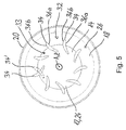
Figuren 1 bis 3 abgewandelten Gemischführungsanordnung, - Figur 5
- eine Schnittansicht gemäß der in
Figur 1 gezeigten Linie V-V, - Figur 6
- eine alternative Ausgestaltung des in
Figur 5 gezeigten Bereichs der Mischanordnung und - Figur 7
- eine weitere alternative Ausgestaltung des in
Figur 5 gezeigten Bereichs der Mischanordnung.
- FIG. 1
- a sectional view of a mixing arrangement according to the invention,
- FIG. 2
- a sectional view of a mixing arrangement according to the invention with a modified mixture guiding arrangement,
- FIG. 3
- a sectional view of a mixing arrangement according to the invention with a relation to the mixing arrangements of
FIGS. 1 and2 modified mixture guiding arrangement, - FIG. 4
- a sectional view of a mixing arrangement according to the invention with a relation to the mixing arrangements of
FIGS. 1 to 3 modified mixture guiding arrangement, - FIG. 5
- a sectional view according to the in
FIG. 1 shown line VV, - FIG. 6
- an alternative embodiment of the in
FIG. 5 shown area of the mixing arrangement and - FIG. 7
- another alternative embodiment of in
FIG. 5 shown area of the mixing arrangement.
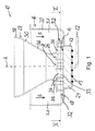
In
Die Mischanordnung 10 umfasst eine Kraftstoffverdampfungsanordnung 12 zur Abgabe von verdampftem Kraftstoff an einer Abdampfungsseite 14 der Kraftstoffverdampfungsanordnung 12. Die Abdampfungsseite 14 der Kraftstoffverdampfungsanordnung 12 kann, wie in
Die Mischanordnung 10 kann ein Gehäuse 16 mit einer Bodenwandung 18 und einer sich an die Bodenwandung 18 anschließenden Umfangswandung 20 aufweisen. Die Kraftstoffverdampfungsanordnung 12 kann an der Bodenwandung 18 derart positioniert sein, dass sich die Umfangswandung 20 im Wesentlichen parallel zur Flächennormalen A erstreckt.The mixing
Die Kraftstoffverdampfungsanordnung 12 kann einen flüssigen Kraftstoff aus einer Kraftstoffzufuhrleitung 22 aufnehmenden und durch Kapillarförderwirkung zur Abdampfungsseite 14 transportierenden, porösen Verdampfungskörper 24 umfassen.The
Hierdurch kann für eine zuverlässige Verdampfung von Kraftstoff gesorgt werden, welche zudem weitestgehend unabhängig von der Positionierung der Mischanordnung 10 ist.This can provide for a reliable evaporation of fuel, which is also largely independent of the positioning of the mixing
Um insbesondere in einer Betriebsstartphase der Mischanordnung 10 bzw. eines Heizgeräts, in welchem die Mischanordnung 10 eingebaut ist, für eine zuverlässige Verdampfung sorgen zu können, kann die Kraftstoffverdampfungsanordnung 12 eine Heizanordnung 13 umfassen. Diese kann beispielsweise spiralförmig ausgebildet und an einer von der Abdampfungsseite 14 der Kraftstoffverdampfungsanordnung 12 gegenüberliegenden Seite angeordnet sein. Eine hohe Wärmeleitfähigkeit zwischen Heizanordnung 13 und Kraftstoffverdampfungsanordnung 12 kann durch eine stoffschlüssige Verbindung zwischen Kraftstoffverdampfungsanordnung 12 und Heizanordnung 13 bereitgestellt werden.In order to be able to ensure reliable evaporation, in particular in an operating start phase of the mixing
Die Mischanordnung 10 umfasst zudem eine der Kraftstoffverdampfungsanordnung 12 an der Abdampfungsseite 14 wenigstens teilweise gegenüberliegend angeordnete Luft-Kraftstoff-Mischeinheit 26 zur Durchmischung von an der Abdampfungsseite 14 abgegebenem Kraftstoff mit Luft. Mit einer derartigen Luft-Kraftstoff-Mischeinheit 26 kann zunächst für ein definiertes Luft-Kraftstoff-Verhältnis gesorgt werden, bevor das Luft-Kraftstoff-Gemisch nachgeschalteten Funktionsbereichen, wie etwa einer in Figur 1 nicht dargestellten Brennkammer, zugeführt wird. Da die Zusammensetzung der im Verbrennungsprozess freigesetzten Abgase maßgeblich von dem Luft-Kraftstoff-Verhältnis abhängt, kann durch eine definierte Einstellung des Luft-Kraftstoff-Verhältnisses letztlich auch die Zusammensetzung der Abgase und somit auch der Schadstoffanteil kontrolliert werden.The mixing
Wie in
Um Kraftstoffdampf besonders einfach in die Luft-Kraftstoff-Mischeinheit 26 einführen zu können und um in der Luft-Kraftstoff-Mischeinheit 26 erzeugtes Luft-Kraftstoff-Gemisch besonders einfach aus dieser abführen zu können, kann die Luft-Kraftstoff-Mischeinheit 26, wie in
In der in
Die Anordnung der Leitelemente 34 in einer zu der Flächennormalen A orthogonalen Ebene ist in der Schnittdarstellung der
Eine alternativ ausgestaltete Luft-Kraftstoff-Mischeinheit 126 mit alternativ ausgestalteten Leitelemente 134 ist in
Eine weitere, alternativ ausgestaltete Luft-Kraftstoff-Mischeinheit 226 ist in
Zu den Luft-Kraftstoff-Mischeinheiten 126 und 226 sei noch angemerkt, dass auch bei ihnen zwischen unmittelbar benachbarten Leitelementen 134 bzw. 234 Einströmbereiche 132 bzw. 232 bzw. Strömungskanäle 133 bzw. 233 vorgesehen sein können. Im Übrigen sei darauf hingewiesen, dass in einer Luft-Kraftstoff-Mischeinheit nicht alle Leitelemente identisch sein müssen. Beispielsweise können in einer Luft-Kraftstoff-Mischeinheit Leitelemente mit geraden Strömungsablenkflächen mit Leitelementen mit einer konvexen oder/und einer konkaven Strömungsablenkfläche kombiniert werden.It should also be noted for the air-
Die Gemischführungsanordnung 28 kann, wie in
Die Gemischführungsanordnung kann mit unterschiedlicher Gestalt ausgebildet sein. Diese kann beispielsweise wenigstens bereichsweise konisch oder/und wenigstens bereichsweise konvex oder/und wenigstens bereichsweise konkav sich erweiternd ausgebildet sein. Sie kann jedoch auch sich verjüngende Abschnitte aufweisen, welche zu einer Geschwindigkeitszunahme des strömenden Luft-Kraftstoff-Gemisches führen. Hierdurch können Verwirbelungen im Strömungsfeld des Luft-Kraftstoff-Gemisches erzeugt werden, welche zu einer weiteren Durchmischung von Luft und Kraftstoffdampf beitragen.The mixture guiding arrangement may be formed with a different shape. This can, for example, at least partially conically and / or at least partially convex and / or at least partially concave be widening. However, it may also have tapered portions, which lead to an increase in the speed of the flowing air-fuel mixture. This can cause turbulence in the flow field of the air-fuel mixture be generated, which contribute to a further mixing of air and fuel vapor.
Die Gemischführungswandung 30 der in
Eine alternativ ausgestaltete Gemischführungsanordnung 128 ist in
Eine weitere alternative Gemischführungsanordnung 228 ist in
Eine weitere alternative Gemischführungsanordnung 328 ist in
Angemerkt sei noch, dass die in den
Im Zusammenhang mit der vorangehend beschriebenen Gemischführungsanordnung kann im Sinne der vorliegenden Erfindung eine konvexe Erweiterung als eine progressive Erweiterung, beispielsweise als eine progressiv zunehmende Strömungsquerschnittsfläche, verstanden werden. Eine konkave Erweiterung kann als eine degressive Erweiterung, beispielsweise als eine degressiv zunehmende Strömungsquerschnittsfläche, verstanden werden. Eine konische Erweiterung kann als eine konstante Erweiterung, beispielsweise als eine konstant zunehmende Strömungsquerschnittsfläche, verstanden werden.For the purposes of the present invention, in connection with the previously described mixture-guiding arrangement, a convex widening can be understood as a progressive widening, for example as a progressively increasing flow cross-sectional area. A concave extension can be understood as a degressive extension, for example as a degressively increasing flow cross-sectional area. A conical enlargement can be understood as a constant extension, for example as a constantly increasing flow cross-sectional area.
Claims (16)
dadurch gekennzeichnet, dass die Luft-Kraftstoff-Mischeinheit (26; 126; 226) wenigstens einen in die Luft-Kraftstoff-Mischeinheit (26; 126; 226) führenden Einströmbereich (32; 132; 232) zur Zufuhr von Luft in die Luft-Kraftstoff-Mischeinheit (26; 126; 226) aufweist.Mixing arrangement (10) according to claim 1,
characterized in that the air-fuel mixing unit (26; 126; 226) comprises at least one inflow region (32; 132; 232) leading into the air-fuel mixing unit (26; 126; 226) for supplying air into the air Fuel mixing unit (26; 126; 226).
dadurch gekennzeichnet, dass die Luft-Kraftstoff-Mischeinheit (26; 126; 226) wenigstens ein Leitelement (34, 34'; 134; 234), vorzugsweise eine Mehrzahl von Leitelementen (34, 34'; 134; 234), zum Leiten von Luft oder/und Kraftstoffdampf aufweist.Mixing arrangement (10) according to one of the preceding claims,
characterized in that the air-fuel mixing unit (26; 126; 226) comprises at least one guide element (34, 34 ';134; 234), preferably a plurality of guide elements (34, 34';134; 234) for conducting Having air and / or fuel vapor.
dadurch gekennzeichnet, dass eine Mehrzahl von um einen Zentralbereich (Z) aufeinanderfolgend angeordneten Leitelementen (34; 134; 234) vorgesehen ist.Mixing arrangement (10) according to claim 3,
characterized in that a plurality of guide elements (34; 134; 234) arranged successively around a central region (Z) is provided.
dadurch gekennzeichnet, dass zwischen wenigstens zwei unmittelbar benachbarten Leitelementen (34, 34'; 134; 234), vorzugsweise zwischen allen unmittelbar benachbarten Leitelementen (34, 34'; 134; 234), ein Einströmbereich (32; 132; 232) bereitgestellt ist.Mixing arrangement (10) according to claim 3 or 4, characterized
characterized in that between at least two immediately adjacent guide elements (34, 34 ';134; 234), preferably between all immediately adjacent guide elements (34, 34 ';134; 234), an inflow region (32; 132; 232) is provided.
dadurch gekennzeichnet, dass die Luft-Kraftstoff-Mischeinheit (26; 126; 226) wenigstens bereichsweise zu der Kraftstoffverdampfungsanordnung (12) hin oder/und von der Kraftstoffverdampfungsanordnung (12) weg offen ist.Mixing arrangement (10) according to one of the preceding claims,
characterized in that the air-fuel mixing unit (26; 126; 226) is at least partially open towards the fuel vaporisation arrangement (12) and / or away from the fuel vaporising arrangement (12).
dadurch gekennzeichnet, dass wenigstens ein Leitelement (34, 34'; 134; 234) wenigstens eine gerade Strömungsablenkfläche (136a, 136b) oder/und gekrümmte Strömungsablenkfläche (36a, 36b; 236a, 236b) aufweist.Mixing arrangement (10) according to one of claims 3 to 6,
characterized in that at least one guide element (34, 34 ';134; 234) has at least one straight flow deflection surface (136a, 136b) and / or curved flow deflection surface (36a, 36b; 236a, 236b).
dadurch gekennzeichnet, dass wenigstens zwei Leitelemente (234), vorzugsweise im Zentralbereich (Z) der Luft-Kraftstoff-Mischeinheit (226), einstückig miteinander ausgebildet sind.Mixing arrangement (10) according to one of claims 3 to 7,
characterized in that at least two guide elements (234), preferably in the central region (Z) of the air-fuel mixing unit (226), are integrally formed with each other.
dadurch gekennzeichnet, dass die Gemischführungsanordnung (28; 128; 228; 328) schalenartig und sich von der Abdampfungsseite (14) der Kraftstoffverdampfungsanordnung (12) weg wenigstens bereichsweise erweiternd ausgebildet ist.Mixing arrangement (10) according to claim 9,
characterized in that the mixture guiding arrangement (28; 128; 228; 328) is cup-shaped and at least partially widening away from the evaporation side (14) of the fuel evaporation arrangement (12).
dadurch gekennzeichnet, dass die Gemischführungsanordnung (28; 128; 228; 328) wenigstens bereichsweise konisch oder/und wenigstens bereichsweise konvex oder/und wenigstens bereichsweise konkav sich erweiternd ausgebildet ist.Mixing arrangement (10) according to claim 10,
characterized in that the mixture guiding arrangement (28; 128; 228; 328) is designed to widen conically at least regionally and / or at least partially convexly and / or at least partially concavely.
dadurch gekennzeichnet, dass eine Gemischführungswandung (30; 130; 230; 330) der Gemischführungsanordnung (28; 128; 228; 328) wenigstens teilweise von der Umfangswandung (20) umgeben ist, wobei zwischen Umfangswandung (20) und Gemischführungswandung (30; 130; 230; 330) ein Luftanströmraum (31) vorgesehen ist.Mixing arrangement (10) according to claim 12 and one of claims 9 to 11,
characterized in that a mixture guide wall (30; 130; 230; 330) of the mixture guide assembly (28; 128; 228; 328) is at least partially surrounded by the peripheral wall (20), between the peripheral wall (20) and mixture guide wall (30; 230, 330) an air inflow space (31) is provided.
dadurch gekennzeichnet, dass die Kraftstoffverdampfungsanordnung (12) einen flüssigen Kraftstoff aus einer Kraftstoffzufuhrleitung (22) aufnehmenden und durch Kapillarförderwirkung zur Abdampfungsseite transportierenden porösen Verdampfungskörper (24) umfasst.Mixing arrangement (10) according to one of the preceding claims,
characterized in that the fuel evaporation assembly (12) comprises a liquid fuel from a fuel supply line (22) receiving and by Kapillarförderwirkung to Abdampfungsseite transporting porous evaporation body (24).
dadurch gekennzeichnet, dass die Kraftstoffverdampfungsanordnung (12) eine Heizanordnung (13) umfasst.Mixing arrangement (10) according to one of the preceding claims,
characterized in that the fuel vaporisation arrangement (12) comprises a heating arrangement (13).
Applications Claiming Priority (1)
| Application Number | Priority Date | Filing Date | Title |
|---|---|---|---|
| DE102015112932.9A DE102015112932A1 (en) | 2015-08-06 | 2015-08-06 | mixing arrangement |
Publications (2)
| Publication Number | Publication Date |
|---|---|
| EP3128233A1 true EP3128233A1 (en) | 2017-02-08 |
| EP3128233B1 EP3128233B1 (en) | 2019-10-09 |
Family
ID=56852054
Family Applications (1)
| Application Number | Title | Priority Date | Filing Date |
|---|---|---|---|
| EP16182129.3A Active EP3128233B1 (en) | 2015-08-06 | 2016-08-01 | Mixing arrangement comprising evaporator |
Country Status (2)
| Country | Link |
|---|---|
| EP (1) | EP3128233B1 (en) |
| DE (1) | DE102015112932A1 (en) |
Cited By (2)
| Publication number | Priority date | Publication date | Assignee | Title |
|---|---|---|---|---|
| CN113386529A (en) * | 2020-03-13 | 2021-09-14 | 埃贝斯佩歇气候控制系统有限公司 | Combustion chamber assembly for a fuel-operated vehicle heater |
| WO2022111843A1 (en) * | 2020-11-24 | 2022-06-02 | Truma Gerätetechnik GmbH & Co. KG | Burner unit |
Citations (3)
| Publication number | Priority date | Publication date | Assignee | Title |
|---|---|---|---|---|
| EP0166329A2 (en) * | 1984-06-25 | 1986-01-02 | AG Verfahrenstechnik für Heizung VTH | Burner, especially a burner for burning liquid fuel in the gaseous state |
| EP1338450A2 (en) * | 2002-02-25 | 2003-08-27 | J. Eberspächer GmbH Co. KG | Heater, in particular for a vehicle |
| DE102005001900A1 (en) * | 2005-01-14 | 2006-07-27 | Webasto Ag | Apparatus and method for providing a homogeneous mixture of fuel and oxidant |
Family Cites Families (5)
| Publication number | Priority date | Publication date | Assignee | Title |
|---|---|---|---|---|
| DE3928214A1 (en) * | 1989-08-25 | 1990-03-08 | Zimmermann Hans Georg Dipl Ing | BURNER WITH FUEL GAS RECIRCULATION FOR FLOWABLE FUELS |
| DE19529994C2 (en) * | 1994-11-10 | 2003-06-26 | Eberspaecher J Gmbh & Co | Evaporator burner for a heater |
| DE19821672A1 (en) * | 1998-05-14 | 1999-11-18 | Walter Swoboda | Pre-mix burner for liquid fuel |
| JP2002310405A (en) * | 2001-04-12 | 2002-10-23 | Denso Corp | Combustor |
| JP2003021322A (en) * | 2001-07-09 | 2003-01-24 | Nippon Soken Inc | Combustion system of heater |
-
2015
- 2015-08-06 DE DE102015112932.9A patent/DE102015112932A1/en not_active Withdrawn
-
2016
- 2016-08-01 EP EP16182129.3A patent/EP3128233B1/en active Active
Patent Citations (3)
| Publication number | Priority date | Publication date | Assignee | Title |
|---|---|---|---|---|
| EP0166329A2 (en) * | 1984-06-25 | 1986-01-02 | AG Verfahrenstechnik für Heizung VTH | Burner, especially a burner for burning liquid fuel in the gaseous state |
| EP1338450A2 (en) * | 2002-02-25 | 2003-08-27 | J. Eberspächer GmbH Co. KG | Heater, in particular for a vehicle |
| DE102005001900A1 (en) * | 2005-01-14 | 2006-07-27 | Webasto Ag | Apparatus and method for providing a homogeneous mixture of fuel and oxidant |
Cited By (6)
| Publication number | Priority date | Publication date | Assignee | Title |
|---|---|---|---|---|
| CN113386529A (en) * | 2020-03-13 | 2021-09-14 | 埃贝斯佩歇气候控制系统有限公司 | Combustion chamber assembly for a fuel-operated vehicle heater |
| EP3879175A1 (en) | 2020-03-13 | 2021-09-15 | Eberspächer Climate Control Systems GmbH | Combustion chamber module for a fuel-powered vehicle heating device |
| US20210283985A1 (en) * | 2020-03-13 | 2021-09-16 | Eberspächer Climate Control Systems GmbH | Combustion chamber assembly unit for a fuel-operated vehicle heater |
| DE102020106881A1 (en) | 2020-03-13 | 2021-09-16 | Eberspächer Climate Control Systems GmbH | Combustion chamber assembly for a fuel-operated vehicle heater |
| US11772455B2 (en) * | 2020-03-13 | 2023-10-03 | Eberspächer Climate Control Systems GmbH | Combustion chamber assembly unit for a fuel-operated vehicle heater |
| WO2022111843A1 (en) * | 2020-11-24 | 2022-06-02 | Truma Gerätetechnik GmbH & Co. KG | Burner unit |
Also Published As
| Publication number | Publication date |
|---|---|
| DE102015112932A1 (en) | 2017-02-09 |
| EP3128233B1 (en) | 2019-10-09 |
Similar Documents
| Publication | Publication Date | Title |
|---|---|---|
| EP1802915B1 (en) | Gas turbine burner | |
| EP0433790B1 (en) | Burner | |
| EP3120075B1 (en) | Evaporation burner arrangement for a mobile, liquid fuel heating device | |
| EP3120077B1 (en) | Vaporization burner for a mobile liquid fuel heating device | |
| EP3128233B1 (en) | Mixing arrangement comprising evaporator | |
| DE2949096C2 (en) | Mixture formers for internal combustion engines | |
| DE102016116687B4 (en) | Combustion chamber assembly for an evaporator burner | |
| EP3447378B1 (en) | Vehicle heating device | |
| DE102012211932B3 (en) | Combustion chamber assembly for vehicle heater, has air intake openings that are formed in combustion chamber with respect to surface normal to peripheral wall of combustion chamber housing along inclined opening longitudinal axis | |
| DE2815916A1 (en) | COMBUSTION CHAMBER FOR GAS TURBINE ENGINES | |
| EP2679897B1 (en) | Oil pre-mix burner with swirler | |
| DE10055365B4 (en) | Evaporation element | |
| DE102006051138A1 (en) | burner assembly | |
| DE102005029687B4 (en) | Spraying device and spray head | |
| EP2282116A2 (en) | Oil premix burner | |
| EP2400215B1 (en) | Oil pre-mix burner with combustion air preheating | |
| DE854289C (en) | Combustion chamber for gas turbines | |
| WO2003076846A1 (en) | Burner, particularly for liquid or gaseous fuels | |
| DE102013109184B4 (en) | Combustion air supply of a mobile heater | |
| DE2358348C2 (en) | Flame starting system for internal combustion engines | |
| EP1489352B1 (en) | Mixing Device for an Oil- or Gasburner | |
| WO2021130000A1 (en) | Flow-directing element, flow-directing system and heating apparatus | |
| DE102009043681B4 (en) | Burner for liquid fuel | |
| WO2011022847A1 (en) | Burner for generating a hot gas stream | |
| DE102009013187A1 (en) | Atomizing device for liquid fuels |
Legal Events
| Date | Code | Title | Description |
|---|---|---|---|
| PUAI | Public reference made under article 153(3) epc to a published international application that has entered the european phase |
Free format text: ORIGINAL CODE: 0009012 |
|
| STAA | Information on the status of an ep patent application or granted ep patent |
Free format text: STATUS: THE APPLICATION HAS BEEN PUBLISHED |
|
| AK | Designated contracting states |
Kind code of ref document: A1 Designated state(s): AL AT BE BG CH CY CZ DE DK EE ES FI FR GB GR HR HU IE IS IT LI LT LU LV MC MK MT NL NO PL PT RO RS SE SI SK SM TR |
|
| AX | Request for extension of the european patent |
Extension state: BA ME |
|
| STAA | Information on the status of an ep patent application or granted ep patent |
Free format text: STATUS: REQUEST FOR EXAMINATION WAS MADE |
|
| 17P | Request for examination filed |
Effective date: 20170808 |
|
| RBV | Designated contracting states (corrected) |
Designated state(s): AL AT BE BG CH CY CZ DE DK EE ES FI FR GB GR HR HU IE IS IT LI LT LU LV MC MK MT NL NO PL PT RO RS SE SI SK SM TR |
|
| GRAP | Despatch of communication of intention to grant a patent |
Free format text: ORIGINAL CODE: EPIDOSNIGR1 |
|
| STAA | Information on the status of an ep patent application or granted ep patent |
Free format text: STATUS: GRANT OF PATENT IS INTENDED |
|
| RIC1 | Information provided on ipc code assigned before grant |
Ipc: F23D 5/18 20060101ALI20190524BHEP Ipc: F23D 5/12 20060101ALI20190524BHEP Ipc: B60H 1/22 20060101ALI20190524BHEP Ipc: F23D 11/44 20060101ALI20190524BHEP Ipc: F23D 3/40 20060101AFI20190524BHEP |
|
| INTG | Intention to grant announced |
Effective date: 20190619 |
|
| GRAS | Grant fee paid |
Free format text: ORIGINAL CODE: EPIDOSNIGR3 |
|
| GRAA | (expected) grant |
Free format text: ORIGINAL CODE: 0009210 |
|
| STAA | Information on the status of an ep patent application or granted ep patent |
Free format text: STATUS: THE PATENT HAS BEEN GRANTED |
|
| AK | Designated contracting states |
Kind code of ref document: B1 Designated state(s): AL AT BE BG CH CY CZ DE DK EE ES FI FR GB GR HR HU IE IS IT LI LT LU LV MC MK MT NL NO PL PT RO RS SE SI SK SM TR |
|
| REG | Reference to a national code |
Ref country code: GB Ref legal event code: FG4D Free format text: NOT ENGLISH |
|
| REG | Reference to a national code |
Ref country code: CH Ref legal event code: EP |
|
| REG | Reference to a national code |
Ref country code: IE Ref legal event code: FG4D Free format text: LANGUAGE OF EP DOCUMENT: GERMAN |
|
| REG | Reference to a national code |
Ref country code: DE Ref legal event code: R096 Ref document number: 502016006977 Country of ref document: DE |
|
| REG | Reference to a national code |
Ref country code: SE Ref legal event code: TRGR |
|
| REG | Reference to a national code |
Ref country code: AT Ref legal event code: REF Ref document number: 1189267 Country of ref document: AT Kind code of ref document: T Effective date: 20191115 |
|
| REG | Reference to a national code |
Ref country code: NL Ref legal event code: MP Effective date: 20191009 |
|
| REG | Reference to a national code |
Ref country code: LT Ref legal event code: MG4D |
|
| PG25 | Lapsed in a contracting state [announced via postgrant information from national office to epo] |
Ref country code: GR Free format text: LAPSE BECAUSE OF FAILURE TO SUBMIT A TRANSLATION OF THE DESCRIPTION OR TO PAY THE FEE WITHIN THE PRESCRIBED TIME-LIMIT Effective date: 20200110 Ref country code: FI Free format text: LAPSE BECAUSE OF FAILURE TO SUBMIT A TRANSLATION OF THE DESCRIPTION OR TO PAY THE FEE WITHIN THE PRESCRIBED TIME-LIMIT Effective date: 20191009 Ref country code: PT Free format text: LAPSE BECAUSE OF FAILURE TO SUBMIT A TRANSLATION OF THE DESCRIPTION OR TO PAY THE FEE WITHIN THE PRESCRIBED TIME-LIMIT Effective date: 20200210 Ref country code: NL Free format text: LAPSE BECAUSE OF FAILURE TO SUBMIT A TRANSLATION OF THE DESCRIPTION OR TO PAY THE FEE WITHIN THE PRESCRIBED TIME-LIMIT Effective date: 20191009 Ref country code: PL Free format text: LAPSE BECAUSE OF FAILURE TO SUBMIT A TRANSLATION OF THE DESCRIPTION OR TO PAY THE FEE WITHIN THE PRESCRIBED TIME-LIMIT Effective date: 20191009 Ref country code: LT Free format text: LAPSE BECAUSE OF FAILURE TO SUBMIT A TRANSLATION OF THE DESCRIPTION OR TO PAY THE FEE WITHIN THE PRESCRIBED TIME-LIMIT Effective date: 20191009 Ref country code: ES Free format text: LAPSE BECAUSE OF FAILURE TO SUBMIT A TRANSLATION OF THE DESCRIPTION OR TO PAY THE FEE WITHIN THE PRESCRIBED TIME-LIMIT Effective date: 20191009 Ref country code: BG Free format text: LAPSE BECAUSE OF FAILURE TO SUBMIT A TRANSLATION OF THE DESCRIPTION OR TO PAY THE FEE WITHIN THE PRESCRIBED TIME-LIMIT Effective date: 20200109 Ref country code: NO Free format text: LAPSE BECAUSE OF FAILURE TO SUBMIT A TRANSLATION OF THE DESCRIPTION OR TO PAY THE FEE WITHIN THE PRESCRIBED TIME-LIMIT Effective date: 20200109 Ref country code: LV Free format text: LAPSE BECAUSE OF FAILURE TO SUBMIT A TRANSLATION OF THE DESCRIPTION OR TO PAY THE FEE WITHIN THE PRESCRIBED TIME-LIMIT Effective date: 20191009 |
|
| PG25 | Lapsed in a contracting state [announced via postgrant information from national office to epo] |
Ref country code: RS Free format text: LAPSE BECAUSE OF FAILURE TO SUBMIT A TRANSLATION OF THE DESCRIPTION OR TO PAY THE FEE WITHIN THE PRESCRIBED TIME-LIMIT Effective date: 20191009 Ref country code: HR Free format text: LAPSE BECAUSE OF FAILURE TO SUBMIT A TRANSLATION OF THE DESCRIPTION OR TO PAY THE FEE WITHIN THE PRESCRIBED TIME-LIMIT Effective date: 20191009 Ref country code: IS Free format text: LAPSE BECAUSE OF FAILURE TO SUBMIT A TRANSLATION OF THE DESCRIPTION OR TO PAY THE FEE WITHIN THE PRESCRIBED TIME-LIMIT Effective date: 20200224 |
|
| PG25 | Lapsed in a contracting state [announced via postgrant information from national office to epo] |
Ref country code: AL Free format text: LAPSE BECAUSE OF FAILURE TO SUBMIT A TRANSLATION OF THE DESCRIPTION OR TO PAY THE FEE WITHIN THE PRESCRIBED TIME-LIMIT Effective date: 20191009 |
|
| REG | Reference to a national code |
Ref country code: DE Ref legal event code: R097 Ref document number: 502016006977 Country of ref document: DE |
|
| PG2D | Information on lapse in contracting state deleted |
Ref country code: IS |
|
| PG25 | Lapsed in a contracting state [announced via postgrant information from national office to epo] |
Ref country code: DK Free format text: LAPSE BECAUSE OF FAILURE TO SUBMIT A TRANSLATION OF THE DESCRIPTION OR TO PAY THE FEE WITHIN THE PRESCRIBED TIME-LIMIT Effective date: 20191009 Ref country code: RO Free format text: LAPSE BECAUSE OF FAILURE TO SUBMIT A TRANSLATION OF THE DESCRIPTION OR TO PAY THE FEE WITHIN THE PRESCRIBED TIME-LIMIT Effective date: 20191009 Ref country code: CZ Free format text: LAPSE BECAUSE OF FAILURE TO SUBMIT A TRANSLATION OF THE DESCRIPTION OR TO PAY THE FEE WITHIN THE PRESCRIBED TIME-LIMIT Effective date: 20191009 Ref country code: EE Free format text: LAPSE BECAUSE OF FAILURE TO SUBMIT A TRANSLATION OF THE DESCRIPTION OR TO PAY THE FEE WITHIN THE PRESCRIBED TIME-LIMIT Effective date: 20191009 Ref country code: IS Free format text: LAPSE BECAUSE OF FAILURE TO SUBMIT A TRANSLATION OF THE DESCRIPTION OR TO PAY THE FEE WITHIN THE PRESCRIBED TIME-LIMIT Effective date: 20200209 |
|
| PLBE | No opposition filed within time limit |
Free format text: ORIGINAL CODE: 0009261 |
|
| STAA | Information on the status of an ep patent application or granted ep patent |
Free format text: STATUS: NO OPPOSITION FILED WITHIN TIME LIMIT |
|
| REG | Reference to a national code |
Ref country code: DE Ref legal event code: R082 Ref document number: 502016006977 Country of ref document: DE Representative=s name: RUTTENSPERGER LACHNIT TROSSIN GOMOLL, PATENT- , DE Ref country code: DE Ref legal event code: R081 Ref document number: 502016006977 Country of ref document: DE Owner name: EBERSPAECHER CLIMATE CONTROL SYSTEMS GMBH, DE Free format text: FORMER OWNER: EBERSPAECHER CLIMATE CONTROL SYSTEMS GMBH & CO. KG, 73730 ESSLINGEN, DE |
|
| PG25 | Lapsed in a contracting state [announced via postgrant information from national office to epo] |
Ref country code: IT Free format text: LAPSE BECAUSE OF FAILURE TO SUBMIT A TRANSLATION OF THE DESCRIPTION OR TO PAY THE FEE WITHIN THE PRESCRIBED TIME-LIMIT Effective date: 20191009 Ref country code: SK Free format text: LAPSE BECAUSE OF FAILURE TO SUBMIT A TRANSLATION OF THE DESCRIPTION OR TO PAY THE FEE WITHIN THE PRESCRIBED TIME-LIMIT Effective date: 20191009 Ref country code: SM Free format text: LAPSE BECAUSE OF FAILURE TO SUBMIT A TRANSLATION OF THE DESCRIPTION OR TO PAY THE FEE WITHIN THE PRESCRIBED TIME-LIMIT Effective date: 20191009 |
|
| 26N | No opposition filed |
Effective date: 20200710 |
|
| PG25 | Lapsed in a contracting state [announced via postgrant information from national office to epo] |
Ref country code: SI Free format text: LAPSE BECAUSE OF FAILURE TO SUBMIT A TRANSLATION OF THE DESCRIPTION OR TO PAY THE FEE WITHIN THE PRESCRIBED TIME-LIMIT Effective date: 20191009 |
|
| PG25 | Lapsed in a contracting state [announced via postgrant information from national office to epo] |
Ref country code: MC Free format text: LAPSE BECAUSE OF FAILURE TO SUBMIT A TRANSLATION OF THE DESCRIPTION OR TO PAY THE FEE WITHIN THE PRESCRIBED TIME-LIMIT Effective date: 20191009 |
|
| REG | Reference to a national code |
Ref country code: CH Ref legal event code: PL |
|
| PG25 | Lapsed in a contracting state [announced via postgrant information from national office to epo] |
Ref country code: CH Free format text: LAPSE BECAUSE OF NON-PAYMENT OF DUE FEES Effective date: 20200831 Ref country code: LI Free format text: LAPSE BECAUSE OF NON-PAYMENT OF DUE FEES Effective date: 20200831 Ref country code: LU Free format text: LAPSE BECAUSE OF NON-PAYMENT OF DUE FEES Effective date: 20200801 |
|
| REG | Reference to a national code |
Ref country code: BE Ref legal event code: MM Effective date: 20200831 |
|
| PG25 | Lapsed in a contracting state [announced via postgrant information from national office to epo] |
Ref country code: BE Free format text: LAPSE BECAUSE OF NON-PAYMENT OF DUE FEES Effective date: 20200831 Ref country code: IE Free format text: LAPSE BECAUSE OF NON-PAYMENT OF DUE FEES Effective date: 20200801 |
|
| PG25 | Lapsed in a contracting state [announced via postgrant information from national office to epo] |
Ref country code: TR Free format text: LAPSE BECAUSE OF FAILURE TO SUBMIT A TRANSLATION OF THE DESCRIPTION OR TO PAY THE FEE WITHIN THE PRESCRIBED TIME-LIMIT Effective date: 20191009 Ref country code: MT Free format text: LAPSE BECAUSE OF FAILURE TO SUBMIT A TRANSLATION OF THE DESCRIPTION OR TO PAY THE FEE WITHIN THE PRESCRIBED TIME-LIMIT Effective date: 20191009 Ref country code: CY Free format text: LAPSE BECAUSE OF FAILURE TO SUBMIT A TRANSLATION OF THE DESCRIPTION OR TO PAY THE FEE WITHIN THE PRESCRIBED TIME-LIMIT Effective date: 20191009 |
|
| PG25 | Lapsed in a contracting state [announced via postgrant information from national office to epo] |
Ref country code: MK Free format text: LAPSE BECAUSE OF FAILURE TO SUBMIT A TRANSLATION OF THE DESCRIPTION OR TO PAY THE FEE WITHIN THE PRESCRIBED TIME-LIMIT Effective date: 20191009 |
|
| REG | Reference to a national code |
Ref country code: AT Ref legal event code: MM01 Ref document number: 1189267 Country of ref document: AT Kind code of ref document: T Effective date: 20210801 |
|
| PG25 | Lapsed in a contracting state [announced via postgrant information from national office to epo] |
Ref country code: AT Free format text: LAPSE BECAUSE OF NON-PAYMENT OF DUE FEES Effective date: 20210801 |
|
| PGFP | Annual fee paid to national office [announced via postgrant information from national office to epo] |
Ref country code: GB Payment date: 20230824 Year of fee payment: 8 |
|
| PGFP | Annual fee paid to national office [announced via postgrant information from national office to epo] |
Ref country code: SE Payment date: 20230823 Year of fee payment: 8 Ref country code: FR Payment date: 20230821 Year of fee payment: 8 Ref country code: DE Payment date: 20230831 Year of fee payment: 8 |