EP3128216B1 - Hydraulic valve - Google Patents
Hydraulic valve Download PDFInfo
- Publication number
- EP3128216B1 EP3128216B1 EP15180222.0A EP15180222A EP3128216B1 EP 3128216 B1 EP3128216 B1 EP 3128216B1 EP 15180222 A EP15180222 A EP 15180222A EP 3128216 B1 EP3128216 B1 EP 3128216B1
- Authority
- EP
- European Patent Office
- Prior art keywords
- spool
- hydraulic
- slot
- fluid path
- spool valve
- Prior art date
- Legal status (The legal status is an assumption and is not a legal conclusion. Google has not performed a legal analysis and makes no representation as to the accuracy of the status listed.)
- Active
Links
- 239000012530 fluid Substances 0.000 claims description 58
- 238000004519 manufacturing process Methods 0.000 description 10
- 238000005553 drilling Methods 0.000 description 5
- 230000000694 effects Effects 0.000 description 3
- RZVHIXYEVGDQDX-UHFFFAOYSA-N 9,10-anthraquinone Chemical compound C1=CC=C2C(=O)C3=CC=CC=C3C(=O)C2=C1 RZVHIXYEVGDQDX-UHFFFAOYSA-N 0.000 description 2
- 238000000034 method Methods 0.000 description 2
- 230000000712 assembly Effects 0.000 description 1
- 238000000429 assembly Methods 0.000 description 1
- 238000010276 construction Methods 0.000 description 1
- 238000006073 displacement reaction Methods 0.000 description 1
- 230000013011 mating Effects 0.000 description 1
- 238000003801 milling Methods 0.000 description 1
- 238000012986 modification Methods 0.000 description 1
- 230000004048 modification Effects 0.000 description 1
- 230000036316 preload Effects 0.000 description 1
- 230000002028 premature Effects 0.000 description 1
- 230000003134 recirculating effect Effects 0.000 description 1
Images


Classifications
-
- F—MECHANICAL ENGINEERING; LIGHTING; HEATING; WEAPONS; BLASTING
- F15—FLUID-PRESSURE ACTUATORS; HYDRAULICS OR PNEUMATICS IN GENERAL
- F15B—SYSTEMS ACTING BY MEANS OF FLUIDS IN GENERAL; FLUID-PRESSURE ACTUATORS, e.g. SERVOMOTORS; DETAILS OF FLUID-PRESSURE SYSTEMS, NOT OTHERWISE PROVIDED FOR
- F15B13/00—Details of servomotor systems ; Valves for servomotor systems
- F15B13/02—Fluid distribution or supply devices characterised by their adaptation to the control of servomotors
- F15B13/04—Fluid distribution or supply devices characterised by their adaptation to the control of servomotors for use with a single servomotor
- F15B13/0401—Valve members; Fluid interconnections therefor
- F15B13/0402—Valve members; Fluid interconnections therefor for linearly sliding valves, e.g. spool valves
-
- F—MECHANICAL ENGINEERING; LIGHTING; HEATING; WEAPONS; BLASTING
- F15—FLUID-PRESSURE ACTUATORS; HYDRAULICS OR PNEUMATICS IN GENERAL
- F15B—SYSTEMS ACTING BY MEANS OF FLUIDS IN GENERAL; FLUID-PRESSURE ACTUATORS, e.g. SERVOMOTORS; DETAILS OF FLUID-PRESSURE SYSTEMS, NOT OTHERWISE PROVIDED FOR
- F15B18/00—Parallel arrangements of independent servomotor systems
-
- F—MECHANICAL ENGINEERING; LIGHTING; HEATING; WEAPONS; BLASTING
- F16—ENGINEERING ELEMENTS AND UNITS; GENERAL MEASURES FOR PRODUCING AND MAINTAINING EFFECTIVE FUNCTIONING OF MACHINES OR INSTALLATIONS; THERMAL INSULATION IN GENERAL
- F16K—VALVES; TAPS; COCKS; ACTUATING-FLOATS; DEVICES FOR VENTING OR AERATING
- F16K11/00—Multiple-way valves, e.g. mixing valves; Pipe fittings incorporating such valves
- F16K11/02—Multiple-way valves, e.g. mixing valves; Pipe fittings incorporating such valves with all movable sealing faces moving as one unit
- F16K11/06—Multiple-way valves, e.g. mixing valves; Pipe fittings incorporating such valves with all movable sealing faces moving as one unit comprising only sliding valves, i.e. sliding closure elements
- F16K11/065—Multiple-way valves, e.g. mixing valves; Pipe fittings incorporating such valves with all movable sealing faces moving as one unit comprising only sliding valves, i.e. sliding closure elements with linearly sliding closure members
- F16K11/07—Multiple-way valves, e.g. mixing valves; Pipe fittings incorporating such valves with all movable sealing faces moving as one unit comprising only sliding valves, i.e. sliding closure elements with linearly sliding closure members with cylindrical slides
- F16K11/0716—Multiple-way valves, e.g. mixing valves; Pipe fittings incorporating such valves with all movable sealing faces moving as one unit comprising only sliding valves, i.e. sliding closure elements with linearly sliding closure members with cylindrical slides with fluid passages through the valve member
-
- F—MECHANICAL ENGINEERING; LIGHTING; HEATING; WEAPONS; BLASTING
- F16—ENGINEERING ELEMENTS AND UNITS; GENERAL MEASURES FOR PRODUCING AND MAINTAINING EFFECTIVE FUNCTIONING OF MACHINES OR INSTALLATIONS; THERMAL INSULATION IN GENERAL
- F16K—VALVES; TAPS; COCKS; ACTUATING-FLOATS; DEVICES FOR VENTING OR AERATING
- F16K31/00—Actuating devices; Operating means; Releasing devices
- F16K31/44—Mechanical actuating means
- F16K31/52—Mechanical actuating means with crank, eccentric, or cam
-
- F—MECHANICAL ENGINEERING; LIGHTING; HEATING; WEAPONS; BLASTING
- F16—ENGINEERING ELEMENTS AND UNITS; GENERAL MEASURES FOR PRODUCING AND MAINTAINING EFFECTIVE FUNCTIONING OF MACHINES OR INSTALLATIONS; THERMAL INSULATION IN GENERAL
- F16K—VALVES; TAPS; COCKS; ACTUATING-FLOATS; DEVICES FOR VENTING OR AERATING
- F16K31/00—Actuating devices; Operating means; Releasing devices
- F16K31/44—Mechanical actuating means
- F16K31/60—Handles
- F16K31/602—Pivoting levers, e.g. single-sided
-
- F—MECHANICAL ENGINEERING; LIGHTING; HEATING; WEAPONS; BLASTING
- F15—FLUID-PRESSURE ACTUATORS; HYDRAULICS OR PNEUMATICS IN GENERAL
- F15B—SYSTEMS ACTING BY MEANS OF FLUIDS IN GENERAL; FLUID-PRESSURE ACTUATORS, e.g. SERVOMOTORS; DETAILS OF FLUID-PRESSURE SYSTEMS, NOT OTHERWISE PROVIDED FOR
- F15B13/00—Details of servomotor systems ; Valves for servomotor systems
- F15B13/12—Special measures for increasing the sensitivity of the system
-
- F—MECHANICAL ENGINEERING; LIGHTING; HEATING; WEAPONS; BLASTING
- F15—FLUID-PRESSURE ACTUATORS; HYDRAULICS OR PNEUMATICS IN GENERAL
- F15B—SYSTEMS ACTING BY MEANS OF FLUIDS IN GENERAL; FLUID-PRESSURE ACTUATORS, e.g. SERVOMOTORS; DETAILS OF FLUID-PRESSURE SYSTEMS, NOT OTHERWISE PROVIDED FOR
- F15B2211/00—Circuits for servomotor systems
- F15B2211/30—Directional control
- F15B2211/32—Directional control characterised by the type of actuation
- F15B2211/321—Directional control characterised by the type of actuation mechanically
- F15B2211/324—Directional control characterised by the type of actuation mechanically manually, e.g. by using a lever or pedal
-
- F—MECHANICAL ENGINEERING; LIGHTING; HEATING; WEAPONS; BLASTING
- F15—FLUID-PRESSURE ACTUATORS; HYDRAULICS OR PNEUMATICS IN GENERAL
- F15B—SYSTEMS ACTING BY MEANS OF FLUIDS IN GENERAL; FLUID-PRESSURE ACTUATORS, e.g. SERVOMOTORS; DETAILS OF FLUID-PRESSURE SYSTEMS, NOT OTHERWISE PROVIDED FOR
- F15B2211/00—Circuits for servomotor systems
- F15B2211/40—Flow control
- F15B2211/415—Flow control characterised by the connections of the flow control means in the circuit
- F15B2211/41581—Flow control characterised by the connections of the flow control means in the circuit being connected to an output member and a return line
Definitions
- This disclosure relates to hydraulic spool valves (also referred to as hydraulic servo valves), particularly those used in duplex hydraulic systems for redundancy such as are often used in aerospace applications.
- Duplex hydraulic systems are used for example in aircraft actuator systems for redundancy and safety so that if one system fails, the other remains operational, allowing continued control of the relevant system.
- the main rotor actuator in a helicopter typically uses a duplex control system.
- Failure modes may include seal failures (leaks), pipe bursts, component structural failure or pump failure. Triplex and even quadruplex systems are also used in some applications.
- Hydraulic spool valves in Flight Control actuators are usually driven by a mechanical lever connected to the pilots input lever which is in turn connected to the pilot's controls by a mechanical linkage.
- two valves are used, one for each system, driven by a single layshaft and lever assembly. Synchronization of these two valves is critical to avoid potentially damaging 'force fight' between the two hydraulic systems. Force fight is created by the two valves being out of synchronization and this can lead to pressure intensification within the actuator. This intensification can cause premature seal failures and may also cause fatigue damage within the actuator.
- a hydraulic spool valve comprising a drive lever and a spool, the spool comprising: a pressure chamber for connecting a pressure line to a hydraulic cylinder; at least one return chamber for connecting the hydraulic cylinder to a reservoir; and an actuator slot receiving the drive lever, wherein the actuator slot comprises a wall; wherein the spool further comprises a fluid path connecting said pressure chamber to said actuator slot and a pressure plate movably mounted in the slot such that in use it is disposed between the fluid path and the drive lever so as to maintain contact with the drive lever and to maintain contact between the drive lever and the wall of the slot opposite to the pressure plate.
- the pressure plate and pressurized fluid path of this spool essentially provide a preload device which utilizes the hydraulic pressure within the valve to reduce the effect of backlash.
- the drive lever is held firmly in place within the slot as it is pressed against the opposite wall of the slot.
- the system can be configured so that there is no potentially damaging force fight between two (or more) valves within a duplex (or higher order) system as the drive lever will act on the two (or more) spools in unison, i.e. it will effect perfectly simultaneous movement of the two (or more) spools whereas a system with backlash would have resulted in one spool moving before the other.
- seals could be provided on or around the pressure plate to prevent the pressurized fluid from escaping from behind the pressure plate.
- seals add complexity and cost and therefore it is preferred to provide no fluid tight seals around the pressure plate.
- the fluid path, actuator slot and return chamber are arranged such that fluid passing through the fluid path into the actuator slot drains to the return chamber. Thus the fluid can leak out from behind the pressure plate into the actuator slot and from there it simply drains to the return line.
- no seals are provided between the actuator slot and the return chamber.
- the fluid path may take any form and may be positioned anywhere on or around the spool.
- the spool comprises a shaft in which the pressure chamber and return chamber are formed and the fluid path is formed internally of the shaft. Forming the fluid path internally of the shaft is spatially efficient and means that the path does not interfere with any other operational parts of the spool shaft and valve. Also no additional conduits are required.
- the fluid path comprises an axial bore along the shaft.
- An axial bore may be formed on the central axis of the shaft or may simply be parallel with the axis, depending on the particular implementation.
- a bore can be formed simply by drilling into the shaft and is thus a simple modification that can be made to existing manufacturing processes without necessarily completely redesigning the spool or spool shaft. It may even be possible for an existing spool to be modified to the new design.
- the fluid path also comprises a transverse bore from the pressure chamber that connects with the axial bore.
- the axial bore provides the opening to the pressure plate and actuator chamber and the transverse bore provides the opening into the pressure chamber. Together the two bores form the fluid path and fluidly connect the pressure chamber to the actuator slot.
- the transverse bore may be a radial bore directed towards the central axis of the shaft or it may be parallel to a radius (e.g. if the axial bore is not on the shaft axis). In general it is preferred to provide the axial bore on the shaft axis and a radial transverse bore to connect with it as this improves the symmetry of the spool and is easier for manufacture.
- the transverse bore extends through the whole diameter of the shaft, thus forming two holes in the circumference of the shaft as well as connecting with the axial bore (i.e. forming a T-junction with the axial bore). This arrangement is again easier for manufacture as the depth of the transverse drilling does not need to be precisely controlled and also provides better symmetry and better fatigue and stress resistance.
- the pressure chamber is formed as an annular chamber around the spool shaft and thus both openings of the transverse bore allow pressurized fluid to connect with the axial bore.
- the plate may comprise a cavity on the side facing the fluid path.
- This cavity may be formed by hollowing out (e.g. milling out) a shallow groove or recess in the plate.
- the size of this cavity will determine the force with which the pressure plate presses against the drive lever and thus the size and/or shape of the cavity may be varied depending on the particular design.
- the cavity is preferably sized such that the pressure from the fluid path is sufficient to keep the drive lever pressed firmly against the opposite wall of the slot.
- the fluid path itself may well provide a sufficiently restricted diameter to limit the pressure on the pressure plate. Indeed the bore diameters can be selected to produce the desired pressure. However, if the bore diameter is too large, a flow restrictor may be disposed in the fluid path (e.g. inserted into a bore) in order to further restrict the flow of fluid from the pressure chamber to the actuator slot.
- the pressure plate must be able to move relative to the actuator slot as the high pressure fluid pushes against it.
- the plate may have guides.
- the guides may be formed either on the plate or on the spool shaft, but preferably a component of the guides is formed on each, e.g. as grooves and corresponding rails.
- the guides take the form of projections on the pressure plate that slide in corresponding grooves formed on the spool shaft.
- this disclosure provides a spool valve comprising a spool as described above (optionally including any of the optional or preferred features also described above), comprising: a housing to receive the spool; and fluid connections to connect the pressure chamber and at least one return chamber of the spool to a pump, a hydraulic cylinder and a reservoir.
- this disclosure provides a duplex or higher order hydraulic actuator comprising two or more spool valves as described above (optionally including any of the optional or preferred features also described above), connected to operate in parallel by the same drive mechanism to operate the same hydraulic cylinder.
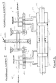
- FIG 1 shows a conventional single spool 20 and layshaft drive 10 from a conventional hydraulic actuator servo valve (and a full implementation is illustrated in Figure 3 ).
- Backlash between the layshaft drive lever 10 and the wall of the slot 22 of the spool 20 in which the layshaft drive lever 10 sits is indicated by reference numeral 26.
- This backlash 26 arises due to manufacturing tolerances or wear of the components over time.
- the backlash 26 is simply a difference in size between the drive lever 10 and the internal width of the slot 22 in which it sits.
- the backlash 26 results in the drive lever 10 having an amount of play within the slot, i.e. the drive lever 10 can move back and forth without causing a corresponding movement of the spool 20.
- This backlash 26 will lead to hysteresis in performance and undesirable force fight in the case of multiple hydraulic systems (e.g. duplex, triplex, etc.). This effect can be minimized by the use of tight tolerances and selective assembly but this is an expensive and time consuming process. Moreover, the backlash that arises due to wear over time can only be corrected by replacing parts so as to achieve a better fit again.
- multiple hydraulic systems e.g. duplex, triplex, etc.
- the spool 20 has a shaft 21 that extends axially and, in use, is moved axially back and forth so as to alter the fluid connections of the valve of which it is a part.
- the shaft 21 is an elongate cylinder (typically of circular cross-section, although this is not essential) with various chambers formed along its length.
- the spool 20 includes a pressure chamber 23 in the middle, located between a first return chamber 24 and a second return chamber 25. Depending on the axial position of the spool 20, the pressure chamber 23 will connect a high pressure inlet to a selected high pressure outlet.
- a hydraulic valve may be used to direct the high pressure fluid from the inlet to a selected side of a piston within a hydraulic cylinder in order to cause movement of the piston within the cylinder.
- the axial position of the spool determines which of the first and second return chambers 24, 25 is connected to a corresponding return line.
- the return line and return chambers 24, 25 allow fluid from the non-pressurised side of the hydraulic cylinder to drain back to a reservoir as the piston moves.
- Figures 2a-e show a spool 20 of similar construction and use to that of Figure 1 , but with the addition of a small piston plate 26 (pressure plate) fitted inside the layshaft drive slot 22 as shown.
- Figure 2a shows a cross-section view from one side.
- Figure 2b shows an isometric view of the shape of the drive lever 10.
- Figure 2c shows an isometric view of the pressure plate (piston plate) 26.
- Figure 2d shows a plan section view.
- Figure 2e shows a side view of the actuator slot 22.
- the plate 26 is pressurized by a fluid path way that is formed from an axial drilling 27 (i.e. a bore drilled in the spool shaft 21) and a transverse drilling 28 (i.e. a bore drilled through the diameter of the shaft 21) that together connect the drive slot 22 to the pressure supply section (pressure chamber) 23 of the spool 20.
- the cross-sectional area of this drilling 27 is sized to produce the optimum plate/lever force to ensure smooth operation of the valve.
- the pressure moves the plate 26 toward the drive lever 10 and ensures that the plate 26 and thus the spool 20 is connected to the layshaft 10 with zero backlash.
- the piston plate 26 can be formed with a reasonably tight fit to the actuator slot 22, but no seals are used to prevent flow of the pressurized fluid from leaking out into the slot 22. However, the leakage of pressurized fluid from this arrangement as the valve operates is collected in the layshaft lever cavity 22 which is connected in turn to the hydraulic system return line via the first return chamber 24 as illustrated by the arrow 30 in Figure 2a .
- the pressure plate 26 has a shallow cavity 29 hollowed out of the side that faces the axial bore 27.
- the cavity 29 is located directly opposite the opening of the axial bore 27 so as to receive fluid that passes along the bore 27.
- the area of the cavity 29 determines the force that is applied to the layshaft 10 and is selected so as to ensure that the layshaft 10 is kept sandwiched between the pressure plate 26 and the opposite wall of the slot 22.
- the plate 26 is also provided with two projections 31, one at either side that align the plate 26 within the slot 22.
- the projections 31 (formed as projecting legs that, together with the main body of the plate 26 form a U-shape) locate in grooves 32 provided on the side of the shaft 21 (specifically on the side of the slot 22) as depicted in Figure 2e .
- the projections 31 and grooves 32 form guides that allow the plate 26 to move back and forth so as to accommodate any backlash that is present between the drive lever 10 and the walls of the slot 22.
- the plate 26 can also move to accommodate any backlash that might develop through wear of either the drive lever 10 or the walls of the slot 22 over time.
- Figure 3 schematically shows a duplex hydraulic actuator system 40 with a first hydraulic system 41 and a second hydraulic system 45.
- First hydraulic system 41 has a first spool valve 42 which is actuated via first mechanical linkage 43 by common input lever 44.
- Second hydraulic system 45 has a second spool valve 46 which is actuated via second mechanical linkage 47 by common input lever 44.
- Hydraulic cylinder 50 houses piston 49.
- Four fluid chambers are formed between the piston 49 and the cylinder 50, namely first fluid chamber 51, second fluid chamber 52, third fluid chamber 53 and fourth fluid chamber 54.
- Second spool valve 46 connects pressure line 59 to line 56, causing hydraulic fluid to flow into second chamber 52.
- line 55 is connected to return line 60 allowing hydraulic fluid to flow out of first chamber 51. Piston 49 is therefore caused to move to the left.
- Second spool valve 46 connects pressure line 59 to line 55, causing hydraulic fluid to flow into first chamber 51.
- line 56 is connected to return line 60 allowing hydraulic fluid to flow out of second chamber 51.
- Piston 49 is therefore caused to move to the right.
Description
- This disclosure relates to hydraulic spool valves (also referred to as hydraulic servo valves), particularly those used in duplex hydraulic systems for redundancy such as are often used in aerospace applications.
- Duplex hydraulic systems are used for example in aircraft actuator systems for redundancy and safety so that if one system fails, the other remains operational, allowing continued control of the relevant system. For example the main rotor actuator in a helicopter typically uses a duplex control system. Failure modes may include seal failures (leaks), pipe bursts, component structural failure or pump failure. Triplex and even quadruplex systems are also used in some applications.
- Hydraulic spool valves in Flight Control actuators are usually driven by a mechanical lever connected to the pilots input lever which is in turn connected to the pilot's controls by a mechanical linkage. Where duplex hydraulic systems are employed for redundancy and safety reasons, two valves are used, one for each system, driven by a single layshaft and lever assembly. Synchronization of these two valves is critical to avoid potentially damaging 'force fight' between the two hydraulic systems. Force fight is created by the two valves being out of synchronization and this can lead to pressure intensification within the actuator. This intensification can cause premature seal failures and may also cause fatigue damage within the actuator. Any backlash or clearances due to manufacturing tolerances between the drive levers and the spools is exploited and can lead to unequal base pressures which in turn can cause unsatisfactory performance. Force fight can occur in actuators with tandem cylinder configurations as shown in
Figure 3 . The four chamber pressures within the cylinder need to be precisely controlled so as to minimise the internal forces generated within the tandem piston and cylinder arrangement. These chamber pressures (referred to as base pressures) are controlled by very small spool displacements (around 0.001 inch) and therefore any small amount of deviation in the valve synchronization between the two hydraulic systems can result in damaging force fights. It is therefore necessary to manufacture to extremely tight tolerances to ensure zero or minimum clearances.EP0073886 discloses a hydraulic control apparatus including a spool and a driver.WO 94/28317 - According to this disclosure there is provided a hydraulic spool valve, comprising a drive lever and a spool, the spool comprising: a pressure chamber for connecting a pressure line to a hydraulic cylinder; at least one return chamber for connecting the hydraulic cylinder to a reservoir; and an actuator slot receiving the drive lever, wherein the actuator slot comprises a wall; wherein the spool further comprises a fluid path connecting said pressure chamber to said actuator slot and a pressure plate movably mounted in the slot such that in use it is disposed between the fluid path and the drive lever so as to maintain contact with the drive lever and to maintain contact between the drive lever and the wall of the slot opposite to the pressure plate.
- The pressure plate and pressurized fluid path of this spool essentially provide a preload device which utilizes the hydraulic pressure within the valve to reduce the effect of backlash. As the pressure pushes the plate against the drive lever, the drive lever is held firmly in place within the slot as it is pressed against the opposite wall of the slot. With this arrangement, there is no requirement for extremely tight tolerances in the manufacture of the actuator slot, thus reducing the manufacturing time and cost. For example, this arrangement allows the use of cost effective manufacturing methods. Also, backlash that would normally have developed over time due to wear does not result in backlash with this arrangement as the pressure plate will still ensure that contact is maintained between the drive lever, the pressure plate and the opposite wall of the slot. In other words, this arrangement is essentially self-compensating for wear.
- As this arrangement eliminates backlash completely, the system can be configured so that there is no potentially damaging force fight between two (or more) valves within a duplex (or higher order) system as the drive lever will act on the two (or more) spools in unison, i.e. it will effect perfectly simultaneous movement of the two (or more) spools whereas a system with backlash would have resulted in one spool moving before the other.
- To minimise backlash it is common practice to machine either the spool slot or drive lever to match exactly the dimensions of the other mating part. This is time consuming and expensive with the added problem of wear that can occur at a later stage of the actuator life.
- In some examples, seals could be provided on or around the pressure plate to prevent the pressurized fluid from escaping from behind the pressure plate. However, such seals add complexity and cost and therefore it is preferred to provide no fluid tight seals around the pressure plate. Preferably the fluid path, actuator slot and return chamber are arranged such that fluid passing through the fluid path into the actuator slot drains to the return chamber. Thus the fluid can leak out from behind the pressure plate into the actuator slot and from there it simply drains to the return line. Preferably no seals are provided between the actuator slot and the return chamber.
- The fluid path may take any form and may be positioned anywhere on or around the spool. However, in some preferred examples the spool comprises a shaft in which the pressure chamber and return chamber are formed and the fluid path is formed internally of the shaft. Forming the fluid path internally of the shaft is spatially efficient and means that the path does not interfere with any other operational parts of the spool shaft and valve. Also no additional conduits are required.
- Preferably the fluid path comprises an axial bore along the shaft. An axial bore may be formed on the central axis of the shaft or may simply be parallel with the axis, depending on the particular implementation. A bore can be formed simply by drilling into the shaft and is thus a simple modification that can be made to existing manufacturing processes without necessarily completely redesigning the spool or spool shaft. It may even be possible for an existing spool to be modified to the new design. Preferably the fluid path also comprises a transverse bore from the pressure chamber that connects with the axial bore. The axial bore provides the opening to the pressure plate and actuator chamber and the transverse bore provides the opening into the pressure chamber. Together the two bores form the fluid path and fluidly connect the pressure chamber to the actuator slot. The transverse bore may be a radial bore directed towards the central axis of the shaft or it may be parallel to a radius (e.g. if the axial bore is not on the shaft axis). In general it is preferred to provide the axial bore on the shaft axis and a radial transverse bore to connect with it as this improves the symmetry of the spool and is easier for manufacture. In preferred examples the transverse bore extends through the whole diameter of the shaft, thus forming two holes in the circumference of the shaft as well as connecting with the axial bore (i.e. forming a T-junction with the axial bore). This arrangement is again easier for manufacture as the depth of the transverse drilling does not need to be precisely controlled and also provides better symmetry and better fatigue and stress resistance. In a typical spool arrangement the pressure chamber is formed as an annular chamber around the spool shaft and thus both openings of the transverse bore allow pressurized fluid to connect with the axial bore.
- In some examples, the plate may comprise a cavity on the side facing the fluid path. This cavity may be formed by hollowing out (e.g. milling out) a shallow groove or recess in the plate. The size of this cavity will determine the force with which the pressure plate presses against the drive lever and thus the size and/or shape of the cavity may be varied depending on the particular design. The cavity is preferably sized such that the pressure from the fluid path is sufficient to keep the drive lever pressed firmly against the opposite wall of the slot.
- The fluid path itself (e.g. the bores) may well provide a sufficiently restricted diameter to limit the pressure on the pressure plate. Indeed the bore diameters can be selected to produce the desired pressure. However, if the bore diameter is too large, a flow restrictor may be disposed in the fluid path (e.g. inserted into a bore) in order to further restrict the flow of fluid from the pressure chamber to the actuator slot.
- The pressure plate must be able to move relative to the actuator slot as the high pressure fluid pushes against it. In order to keep the plate aligned and held in place relative to the spool shaft, the plate may have guides. The guides may be formed either on the plate or on the spool shaft, but preferably a component of the guides is formed on each, e.g. as grooves and corresponding rails. In some preferred examples, the guides take the form of projections on the pressure plate that slide in corresponding grooves formed on the spool shaft. Thus the grooves hold the plate against transverse movement that would cause it to exit the actuator slot, while permitting the axial movement that allows the plate to press against the drive lever.
- According to a further aspect, this disclosure provides a spool valve comprising a spool as described above (optionally including any of the optional or preferred features also described above), comprising: a housing to receive the spool; and fluid connections to connect the pressure chamber and at least one return chamber of the spool to a pump, a hydraulic cylinder and a reservoir.
- According to yet a further aspect, this disclosure provides a duplex or higher order hydraulic actuator comprising two or more spool valves as described above (optionally including any of the optional or preferred features also described above), connected to operate in parallel by the same drive mechanism to operate the same hydraulic cylinder.
- The examples above are described predominantly in relation to aircraft flight control actuators, but they are also applicable to other hydraulic valve applications. For example they could also be used in commercial, non-aerospace hydraulic valve applications (simplex, duplex or higher order) to simplify the manufacture of spool/drive lever assemblies.
- One or more non-limiting examples will now be described, by way of example only, and with reference to the accompanying figures in which:
-
Fig. 1 illustrates the problem of backlash in a spool valve; -
Fig. 2 illustrates an example of this disclosure with an anti-backlash pressure plate; and -
Fig. 3 schematically shows a duplex hydraulic actuator. -
Figure 1 shows a conventionalsingle spool 20 and layshaft drive 10 from a conventional hydraulic actuator servo valve (and a full implementation is illustrated inFigure 3 ). Backlash between thelayshaft drive lever 10 and the wall of theslot 22 of thespool 20 in which thelayshaft drive lever 10 sits is indicated byreference numeral 26. Thisbacklash 26 arises due to manufacturing tolerances or wear of the components over time. Thebacklash 26 is simply a difference in size between thedrive lever 10 and the internal width of theslot 22 in which it sits. Thebacklash 26 results in thedrive lever 10 having an amount of play within the slot, i.e. thedrive lever 10 can move back and forth without causing a corresponding movement of thespool 20. Thisbacklash 26 will lead to hysteresis in performance and undesirable force fight in the case of multiple hydraulic systems (e.g. duplex, triplex, etc.). This effect can be minimized by the use of tight tolerances and selective assembly but this is an expensive and time consuming process. Moreover, the backlash that arises due to wear over time can only be corrected by replacing parts so as to achieve a better fit again. - The
spool 20 has ashaft 21 that extends axially and, in use, is moved axially back and forth so as to alter the fluid connections of the valve of which it is a part. Theshaft 21 is an elongate cylinder (typically of circular cross-section, although this is not essential) with various chambers formed along its length. Thespool 20 includes apressure chamber 23 in the middle, located between afirst return chamber 24 and asecond return chamber 25. Depending on the axial position of thespool 20, thepressure chamber 23 will connect a high pressure inlet to a selected high pressure outlet. In a typical arrangement, a hydraulic valve may be used to direct the high pressure fluid from the inlet to a selected side of a piston within a hydraulic cylinder in order to cause movement of the piston within the cylinder. At the same time, the axial position of the spool determines which of the first andsecond return chambers chambers -
Figures 2a-e show aspool 20 of similar construction and use to that ofFigure 1 , but with the addition of a small piston plate 26 (pressure plate) fitted inside thelayshaft drive slot 22 as shown. -
Figure 2a shows a cross-section view from one side.Figure 2b shows an isometric view of the shape of thedrive lever 10.Figure 2c shows an isometric view of the pressure plate (piston plate) 26.Figure 2d shows a plan section view.Figure 2e shows a side view of theactuator slot 22. - As best illustrated in
Figure 2a , theplate 26 is pressurized by a fluid path way that is formed from an axial drilling 27 (i.e. a bore drilled in the spool shaft 21) and a transverse drilling 28 (i.e. a bore drilled through the diameter of the shaft 21) that together connect thedrive slot 22 to the pressure supply section (pressure chamber) 23 of thespool 20. The cross-sectional area of thisdrilling 27 is sized to produce the optimum plate/lever force to ensure smooth operation of the valve. The pressure moves theplate 26 toward thedrive lever 10 and ensures that theplate 26 and thus thespool 20 is connected to thelayshaft 10 with zero backlash. - The
piston plate 26 can be formed with a reasonably tight fit to theactuator slot 22, but no seals are used to prevent flow of the pressurized fluid from leaking out into theslot 22. However, the leakage of pressurized fluid from this arrangement as the valve operates is collected in thelayshaft lever cavity 22 which is connected in turn to the hydraulic system return line via thefirst return chamber 24 as illustrated by thearrow 30 inFigure 2a . - As shown in
Figure 2c , thepressure plate 26 has ashallow cavity 29 hollowed out of the side that faces theaxial bore 27. Thecavity 29 is located directly opposite the opening of theaxial bore 27 so as to receive fluid that passes along thebore 27. The area of thecavity 29 determines the force that is applied to thelayshaft 10 and is selected so as to ensure that thelayshaft 10 is kept sandwiched between thepressure plate 26 and the opposite wall of theslot 22. Theplate 26 is also provided with twoprojections 31, one at either side that align theplate 26 within theslot 22. The projections 31 (formed as projecting legs that, together with the main body of theplate 26 form a U-shape) locate ingrooves 32 provided on the side of the shaft 21 (specifically on the side of the slot 22) as depicted inFigure 2e . Together theprojections 31 andgrooves 32 form guides that allow theplate 26 to move back and forth so as to accommodate any backlash that is present between thedrive lever 10 and the walls of theslot 22. Theplate 26 can also move to accommodate any backlash that might develop through wear of either thedrive lever 10 or the walls of theslot 22 over time. -
Figure 3 schematically shows a duplex hydraulic actuator system 40 with a first hydraulic system 41 and a secondhydraulic system 45. First hydraulic system 41 has afirst spool valve 42 which is actuated via firstmechanical linkage 43 bycommon input lever 44. Secondhydraulic system 45 has asecond spool valve 46 which is actuated via secondmechanical linkage 47 bycommon input lever 44. -
Hydraulic cylinder 50houses piston 49. Four fluid chambers are formed between thepiston 49 and thecylinder 50, namely firstfluid chamber 51,second fluid chamber 52, thirdfluid chamber 53 and fourthfluid chamber 54. - When
common input lever 44 is moved to the right (in the figure), the twospool valves First spool valve 42 thus connectspressure line 61 toline 58, causing hydraulic fluid to flow intofourth chamber 54. At the same time,line 57 is connected to returnline 62 allowing hydraulic fluid to flow out ofthird chamber 53. Simultaneously,second spool valve 46 connectspressure line 59 toline 56, causing hydraulic fluid to flow intosecond chamber 52. At the same time,line 55 is connected to returnline 60 allowing hydraulic fluid to flow out offirst chamber 51.Piston 49 is therefore caused to move to the left. - When
common input lever 44 is moved to the left (in the figure), the twospool valves First spool valve 42 thus connectspressure line 61 toline 57, causing hydraulic fluid to flow intothird chamber 53. At the same time,line 58 is connected to returnline 62 allowing hydraulic fluid to flow out offourth chamber 54. Simultaneously,second spool valve 46 connectspressure line 59 toline 55, causing hydraulic fluid to flow intofirst chamber 51. At the same time,line 56 is connected to returnline 60 allowing hydraulic fluid to flow out ofsecond chamber 51.Piston 49 is therefore caused to move to the right. - It can be appreciated from
Figure 3 that any backlash in either of the valves will cause onespool valve piston 49 is unable to move withincylinder 50. This pressure build up may for example cause damage to the seals or to the fluid transfer lines. By contrast, when the anti-backlash design ofFigures 2a-2e is employed for both thespool valves
Claims (14)
- A hydraulic spool valve (42, 46), comprising:a drive lever (10); and,a spool (20), the spool comprising:a pressure chamber (23) for connecting a pressure line to a hydraulic cylinder;at least one return chamber (24, 25) for connecting the hydraulic cylinder to a reservoir; andan actuator slot (22) receiving the drive lever (10), wherein the actuator slot (22) comprises a wall;characterised in that the spool further comprises a fluid path connecting said pressure chamber to said actuator slot (22) and a pressure plate (26) movably mounted in the slot such that in use it is disposed between the fluid path (27, 28) and the drive lever so as to maintain contact with the drive lever and to maintain contact between the drive lever (10) and the wall of the slot (22) opposite to the pressure plate (26).
- A hydraulic spool valve (42,46) as claimed in claim 1, wherein said fluid path (27, 28), actuator slot (22) and return chamber (24, 25) are arranged such that fluid passing through the fluid path into the actuator slot drains to the return chamber.
- A hydraulic spool valve (42,46) as claimed in claim 2, wherein no seals are provided between the actuator slot (22) and the return chamber (24, 25).
- A hydraulic spool valve (42,46) as claimed in any preceding claim, wherein the spool comprises a shaft (21) in which the pressure chamber (23) and return chamber (24, 25) are formed and wherein the fluid path (27, 28) is formed internally of the shaft.
- A hydraulic spool valve (42,46) as claimed in claim 4, wherein the fluid path (27, 28) comprises an axial bore (27) along the shaft.
- A hydraulic spool valve (42,46) as claimed in claim 5, wherein the fluid path (27, 28) comprises a transverse bore (28) from the pressure chamber that connects with the axial bore.
- A hydraulic spool valve (42,46) as claimed in claim 6, wherein the transverse bore extends through the whole diameter of the shaft.
- A hydraulic spool valve (42,46) as claimed in any preceding claim, wherein the plate (26) comprises a cavity (29) on the side facing the fluid path
- A hydraulic spool valve (42,46) as claimed in claim 8, wherein the cavity (29) is sized such that the pressure from the fluid path is sufficient to keep the drive lever (10) pressed firmly against the opposite wall of the slot.
- A hydraulic spool valve (42,46) as claimed in any preceding claim, further comprising a flow restrictor in the fluid path.
- A hydraulic spool valve (42,46) as claimed in any preceding claim, wherein the plate has guides (31, 32) to keep it aligned within the slot.
- A hydraulic spool valve (42,46) as claimed in claim 11, wherein the guides are in the form of projections (31) that slide in corresponding grooves (32) formed on the spool shaft.
- A spool valve (42, 46) comprising a spool (20) as claimed in any preceding claim, comprising: a housing to receive the spool; and fluid connections to connect the pressure chamber (23) and at least one return chamber (24, 25) of the spool to a pump, a hydraulic cylinder and a reservoir.
- A duplex or higher order hydraulic actuator (40) comprising two or more spool valves (20) as claimed in claim 13 connected to operate in parallel by the same drive mechanism to operate the same hydraulic cylinder.
Priority Applications (2)
| Application Number | Priority Date | Filing Date | Title |
|---|---|---|---|
| EP15180222.0A EP3128216B1 (en) | 2015-08-07 | 2015-08-07 | Hydraulic valve |
| US15/229,365 US10036408B2 (en) | 2015-08-07 | 2016-08-05 | Hydraulic valve |
Applications Claiming Priority (1)
| Application Number | Priority Date | Filing Date | Title |
|---|---|---|---|
| EP15180222.0A EP3128216B1 (en) | 2015-08-07 | 2015-08-07 | Hydraulic valve |
Publications (2)
| Publication Number | Publication Date |
|---|---|
| EP3128216A1 EP3128216A1 (en) | 2017-02-08 |
| EP3128216B1 true EP3128216B1 (en) | 2019-03-13 |
Family
ID=53794089
Family Applications (1)
| Application Number | Title | Priority Date | Filing Date |
|---|---|---|---|
| EP15180222.0A Active EP3128216B1 (en) | 2015-08-07 | 2015-08-07 | Hydraulic valve |
Country Status (2)
| Country | Link |
|---|---|
| US (1) | US10036408B2 (en) |
| EP (1) | EP3128216B1 (en) |
Families Citing this family (5)
| Publication number | Priority date | Publication date | Assignee | Title |
|---|---|---|---|---|
| US5763159A (en) * | 1991-11-21 | 1998-06-09 | Common Services Agency | Hepatitis-C virus testing |
| EP3406950B1 (en) | 2017-05-25 | 2020-03-11 | Claverham Limited | Hydraulic valve |
| EP3418587B1 (en) | 2017-06-22 | 2020-10-07 | Claverham Limited | Hydraulic valve |
| CN107606241A (en) * | 2017-10-30 | 2018-01-19 | 厦门市福工动力技术有限公司 | A kind of actuation means of banked direction control valves |
| US10808735B2 (en) * | 2018-09-21 | 2020-10-20 | Ford Global Technologies, Llc | Transmission park valve with steel saddle |
Family Cites Families (18)
| Publication number | Priority date | Publication date | Assignee | Title |
|---|---|---|---|---|
| US1908396A (en) * | 1930-09-24 | 1933-05-09 | Bailey Meter Co | Piston |
| US3825670A (en) * | 1973-11-07 | 1974-07-23 | Us Interior | Connector for use in capacitive graded splices |
| US3939870A (en) * | 1974-11-14 | 1976-02-24 | Deltrol Corporation | Combination manual and pilot operated directional control valve |
| US4128047A (en) * | 1975-08-14 | 1978-12-05 | Textron Inc. | Actuator with locking valves |
| EP0068728A1 (en) * | 1981-06-26 | 1983-01-05 | WESTLAND plc | Servo system |
| DE3134858A1 (en) * | 1981-09-03 | 1983-03-17 | Klöckner-Humboldt-Deutz AG, 5000 Köln | HYDRAULIC CONTROL UNIT |
| US4434708A (en) * | 1982-03-05 | 1984-03-06 | General Signal Corporation | Control valve for double-acting piston and valve assemblies |
| US5590525A (en) * | 1993-06-01 | 1997-01-07 | Sundstrand Corporation | Method of preventing cavitation in an axial piston pump during an aiding load and system and valve employing the same |
| DE4426706C1 (en) * | 1994-07-20 | 1995-12-21 | Mannesmann Ag | Servo-hydraulic actuator |
| DE19646445A1 (en) * | 1996-11-11 | 1998-05-14 | Rexroth Mannesmann Gmbh | Valve arrangement |
| IT1321148B1 (en) * | 2000-03-03 | 2003-12-30 | New Holland Italia Spa | HYDRAULIC DISTRIBUTOR. |
| IT1320486B1 (en) * | 2000-05-31 | 2003-12-10 | Rancilio Macchine Per Caffe Sp | COFFEE MACHINE'. |
| KR100345147B1 (en) * | 2000-06-21 | 2002-07-24 | 현대자동차주식회사 | Manual valve of hydraulic control system for automatic transmission |
| US6689007B2 (en) * | 2002-02-05 | 2004-02-10 | Sonnax Industries, Inc. | Manual valve for automatic transmission |
| JP4779437B2 (en) * | 2004-05-31 | 2011-09-28 | パナソニック株式会社 | Wireless communication method and wireless communication apparatus |
| KR100680841B1 (en) * | 2005-12-06 | 2007-02-08 | 현대자동차주식회사 | Manual valve of hydraulic control system for automatic transmission |
| US20150013804A1 (en) * | 2013-07-10 | 2015-01-15 | Husco International, Inc. | Flow responsive latch for holding a spool valve in an open position |
| KR101409765B1 (en) * | 2013-12-09 | 2014-06-19 | 파카코리아(주) | Directional Control Valve for controlling turbine |
-
2015
- 2015-08-07 EP EP15180222.0A patent/EP3128216B1/en active Active
-
2016
- 2016-08-05 US US15/229,365 patent/US10036408B2/en active Active
Non-Patent Citations (1)
| Title |
|---|
| None * |
Also Published As
| Publication number | Publication date |
|---|---|
| US20170037877A1 (en) | 2017-02-09 |
| US10036408B2 (en) | 2018-07-31 |
| EP3128216A1 (en) | 2017-02-08 |
Similar Documents
| Publication | Publication Date | Title |
|---|---|---|
| US10036408B2 (en) | Hydraulic valve | |
| EP1700041B1 (en) | Redundant flow control for hydraulic actuator systems | |
| EP2586966B1 (en) | Rotary actuator | |
| US11933420B2 (en) | Redundant vehicle control systems | |
| JP6503027B2 (en) | Fluid pump and method of manufacturing the same | |
| US20170108141A1 (en) | Rotary valve | |
| US11384871B2 (en) | Axial swage tool | |
| EP3333466B1 (en) | Pneumatic valve | |
| US20180094745A1 (en) | Fluid valve | |
| EP3129660B1 (en) | Servo valve | |
| US20190024806A1 (en) | Spool valve | |
| KR101501903B1 (en) | Hub assembly for controllable pitch propeller | |
| EP0110501B1 (en) | Redundant control actuation system-concentric direct drive valve | |
| US10132419B2 (en) | Valve device with a valve housing having multiple recesses | |
| EP3406950B1 (en) | Hydraulic valve | |
| KR20180043168A (en) | Valve and hydraulic actuating device with a such valve | |
| US20120099991A1 (en) | Hydraulic Variable Pitch Propeller | |
| EP3418587B1 (en) | Hydraulic valve | |
| US10233899B2 (en) | Hydrostatic axial piston machine | |
| US20230003310A1 (en) | Electromagnetic valve | |
| EP3715634B1 (en) | Gear pump bearing with hybrid pad shutoff | |
| EP3822523A1 (en) | Spool valve | |
| EP3377793B1 (en) | Valve actuator indicator arrangement | |
| JP2007092915A (en) | Structure of control valve for hydraulic driving device | |
| JPH0463272B2 (en) |
Legal Events
| Date | Code | Title | Description |
|---|---|---|---|
| PUAI | Public reference made under article 153(3) epc to a published international application that has entered the european phase |
Free format text: ORIGINAL CODE: 0009012 |
|
| STAA | Information on the status of an ep patent application or granted ep patent |
Free format text: STATUS: THE APPLICATION HAS BEEN PUBLISHED |
|
| AK | Designated contracting states |
Kind code of ref document: A1 Designated state(s): AL AT BE BG CH CY CZ DE DK EE ES FI FR GB GR HR HU IE IS IT LI LT LU LV MC MK MT NL NO PL PT RO RS SE SI SK SM TR |
|
| AX | Request for extension of the european patent |
Extension state: BA ME |
|
| STAA | Information on the status of an ep patent application or granted ep patent |
Free format text: STATUS: REQUEST FOR EXAMINATION WAS MADE |
|
| 17P | Request for examination filed |
Effective date: 20170808 |
|
| RBV | Designated contracting states (corrected) |
Designated state(s): AL AT BE BG CH CY CZ DE DK EE ES FI FR GB GR HR HU IE IS IT LI LT LU LV MC MK MT NL NO PL PT RO RS SE SI SK SM TR |
|
| STAA | Information on the status of an ep patent application or granted ep patent |
Free format text: STATUS: EXAMINATION IS IN PROGRESS |
|
| 17Q | First examination report despatched |
Effective date: 20180116 |
|
| GRAP | Despatch of communication of intention to grant a patent |
Free format text: ORIGINAL CODE: EPIDOSNIGR1 |
|
| STAA | Information on the status of an ep patent application or granted ep patent |
Free format text: STATUS: GRANT OF PATENT IS INTENDED |
|
| RAP1 | Party data changed (applicant data changed or rights of an application transferred) |
Owner name: CLAVERHAM LIMITED |
|
| INTG | Intention to grant announced |
Effective date: 20180920 |
|
| GRAS | Grant fee paid |
Free format text: ORIGINAL CODE: EPIDOSNIGR3 |
|
| GRAA | (expected) grant |
Free format text: ORIGINAL CODE: 0009210 |
|
| STAA | Information on the status of an ep patent application or granted ep patent |
Free format text: STATUS: THE PATENT HAS BEEN GRANTED |
|
| AK | Designated contracting states |
Kind code of ref document: B1 Designated state(s): AL AT BE BG CH CY CZ DE DK EE ES FI FR GB GR HR HU IE IS IT LI LT LU LV MC MK MT NL NO PL PT RO RS SE SI SK SM TR |
|
| REG | Reference to a national code |
Ref country code: GB Ref legal event code: FG4D |
|
| REG | Reference to a national code |
Ref country code: CH Ref legal event code: EP Ref country code: AT Ref legal event code: REF Ref document number: 1108164 Country of ref document: AT Kind code of ref document: T Effective date: 20190315 |
|
| REG | Reference to a national code |
Ref country code: IE Ref legal event code: FG4D |
|
| REG | Reference to a national code |
Ref country code: DE Ref legal event code: R096 Ref document number: 602015026197 Country of ref document: DE |
|
| REG | Reference to a national code |
Ref country code: NL Ref legal event code: MP Effective date: 20190313 |
|
| REG | Reference to a national code |
Ref country code: LT Ref legal event code: MG4D |
|
| PG25 | Lapsed in a contracting state [announced via postgrant information from national office to epo] |
Ref country code: SE Free format text: LAPSE BECAUSE OF FAILURE TO SUBMIT A TRANSLATION OF THE DESCRIPTION OR TO PAY THE FEE WITHIN THE PRESCRIBED TIME-LIMIT Effective date: 20190313 Ref country code: LT Free format text: LAPSE BECAUSE OF FAILURE TO SUBMIT A TRANSLATION OF THE DESCRIPTION OR TO PAY THE FEE WITHIN THE PRESCRIBED TIME-LIMIT Effective date: 20190313 Ref country code: FI Free format text: LAPSE BECAUSE OF FAILURE TO SUBMIT A TRANSLATION OF THE DESCRIPTION OR TO PAY THE FEE WITHIN THE PRESCRIBED TIME-LIMIT Effective date: 20190313 Ref country code: NO Free format text: LAPSE BECAUSE OF FAILURE TO SUBMIT A TRANSLATION OF THE DESCRIPTION OR TO PAY THE FEE WITHIN THE PRESCRIBED TIME-LIMIT Effective date: 20190613 |
|
| PG25 | Lapsed in a contracting state [announced via postgrant information from national office to epo] |
Ref country code: BG Free format text: LAPSE BECAUSE OF FAILURE TO SUBMIT A TRANSLATION OF THE DESCRIPTION OR TO PAY THE FEE WITHIN THE PRESCRIBED TIME-LIMIT Effective date: 20190613 Ref country code: GR Free format text: LAPSE BECAUSE OF FAILURE TO SUBMIT A TRANSLATION OF THE DESCRIPTION OR TO PAY THE FEE WITHIN THE PRESCRIBED TIME-LIMIT Effective date: 20190614 Ref country code: LV Free format text: LAPSE BECAUSE OF FAILURE TO SUBMIT A TRANSLATION OF THE DESCRIPTION OR TO PAY THE FEE WITHIN THE PRESCRIBED TIME-LIMIT Effective date: 20190313 Ref country code: HR Free format text: LAPSE BECAUSE OF FAILURE TO SUBMIT A TRANSLATION OF THE DESCRIPTION OR TO PAY THE FEE WITHIN THE PRESCRIBED TIME-LIMIT Effective date: 20190313 Ref country code: NL Free format text: LAPSE BECAUSE OF FAILURE TO SUBMIT A TRANSLATION OF THE DESCRIPTION OR TO PAY THE FEE WITHIN THE PRESCRIBED TIME-LIMIT Effective date: 20190313 Ref country code: RS Free format text: LAPSE BECAUSE OF FAILURE TO SUBMIT A TRANSLATION OF THE DESCRIPTION OR TO PAY THE FEE WITHIN THE PRESCRIBED TIME-LIMIT Effective date: 20190313 |
|
| REG | Reference to a national code |
Ref country code: AT Ref legal event code: MK05 Ref document number: 1108164 Country of ref document: AT Kind code of ref document: T Effective date: 20190313 |
|
| PG25 | Lapsed in a contracting state [announced via postgrant information from national office to epo] |
Ref country code: AL Free format text: LAPSE BECAUSE OF FAILURE TO SUBMIT A TRANSLATION OF THE DESCRIPTION OR TO PAY THE FEE WITHIN THE PRESCRIBED TIME-LIMIT Effective date: 20190313 Ref country code: PT Free format text: LAPSE BECAUSE OF FAILURE TO SUBMIT A TRANSLATION OF THE DESCRIPTION OR TO PAY THE FEE WITHIN THE PRESCRIBED TIME-LIMIT Effective date: 20190713 Ref country code: RO Free format text: LAPSE BECAUSE OF FAILURE TO SUBMIT A TRANSLATION OF THE DESCRIPTION OR TO PAY THE FEE WITHIN THE PRESCRIBED TIME-LIMIT Effective date: 20190313 Ref country code: CZ Free format text: LAPSE BECAUSE OF FAILURE TO SUBMIT A TRANSLATION OF THE DESCRIPTION OR TO PAY THE FEE WITHIN THE PRESCRIBED TIME-LIMIT Effective date: 20190313 Ref country code: ES Free format text: LAPSE BECAUSE OF FAILURE TO SUBMIT A TRANSLATION OF THE DESCRIPTION OR TO PAY THE FEE WITHIN THE PRESCRIBED TIME-LIMIT Effective date: 20190313 Ref country code: EE Free format text: LAPSE BECAUSE OF FAILURE TO SUBMIT A TRANSLATION OF THE DESCRIPTION OR TO PAY THE FEE WITHIN THE PRESCRIBED TIME-LIMIT Effective date: 20190313 Ref country code: SK Free format text: LAPSE BECAUSE OF FAILURE TO SUBMIT A TRANSLATION OF THE DESCRIPTION OR TO PAY THE FEE WITHIN THE PRESCRIBED TIME-LIMIT Effective date: 20190313 |
|
| PG25 | Lapsed in a contracting state [announced via postgrant information from national office to epo] |
Ref country code: PL Free format text: LAPSE BECAUSE OF FAILURE TO SUBMIT A TRANSLATION OF THE DESCRIPTION OR TO PAY THE FEE WITHIN THE PRESCRIBED TIME-LIMIT Effective date: 20190313 Ref country code: SM Free format text: LAPSE BECAUSE OF FAILURE TO SUBMIT A TRANSLATION OF THE DESCRIPTION OR TO PAY THE FEE WITHIN THE PRESCRIBED TIME-LIMIT Effective date: 20190313 |
|
| REG | Reference to a national code |
Ref country code: DE Ref legal event code: R097 Ref document number: 602015026197 Country of ref document: DE |
|
| PG25 | Lapsed in a contracting state [announced via postgrant information from national office to epo] |
Ref country code: IS Free format text: LAPSE BECAUSE OF FAILURE TO SUBMIT A TRANSLATION OF THE DESCRIPTION OR TO PAY THE FEE WITHIN THE PRESCRIBED TIME-LIMIT Effective date: 20190713 Ref country code: AT Free format text: LAPSE BECAUSE OF FAILURE TO SUBMIT A TRANSLATION OF THE DESCRIPTION OR TO PAY THE FEE WITHIN THE PRESCRIBED TIME-LIMIT Effective date: 20190313 |
|
| PLBE | No opposition filed within time limit |
Free format text: ORIGINAL CODE: 0009261 |
|
| STAA | Information on the status of an ep patent application or granted ep patent |
Free format text: STATUS: NO OPPOSITION FILED WITHIN TIME LIMIT |
|
| PG25 | Lapsed in a contracting state [announced via postgrant information from national office to epo] |
Ref country code: DK Free format text: LAPSE BECAUSE OF FAILURE TO SUBMIT A TRANSLATION OF THE DESCRIPTION OR TO PAY THE FEE WITHIN THE PRESCRIBED TIME-LIMIT Effective date: 20190313 |
|
| 26N | No opposition filed |
Effective date: 20191216 |
|
| PG25 | Lapsed in a contracting state [announced via postgrant information from national office to epo] |
Ref country code: SI Free format text: LAPSE BECAUSE OF FAILURE TO SUBMIT A TRANSLATION OF THE DESCRIPTION OR TO PAY THE FEE WITHIN THE PRESCRIBED TIME-LIMIT Effective date: 20190313 |
|
| PG25 | Lapsed in a contracting state [announced via postgrant information from national office to epo] |
Ref country code: TR Free format text: LAPSE BECAUSE OF FAILURE TO SUBMIT A TRANSLATION OF THE DESCRIPTION OR TO PAY THE FEE WITHIN THE PRESCRIBED TIME-LIMIT Effective date: 20190313 |
|
| PG25 | Lapsed in a contracting state [announced via postgrant information from national office to epo] |
Ref country code: LU Free format text: LAPSE BECAUSE OF NON-PAYMENT OF DUE FEES Effective date: 20190807 Ref country code: CH Free format text: LAPSE BECAUSE OF NON-PAYMENT OF DUE FEES Effective date: 20190831 Ref country code: MC Free format text: LAPSE BECAUSE OF FAILURE TO SUBMIT A TRANSLATION OF THE DESCRIPTION OR TO PAY THE FEE WITHIN THE PRESCRIBED TIME-LIMIT Effective date: 20190313 Ref country code: LI Free format text: LAPSE BECAUSE OF NON-PAYMENT OF DUE FEES Effective date: 20190831 |
|
| REG | Reference to a national code |
Ref country code: BE Ref legal event code: MM Effective date: 20190831 |
|
| PG25 | Lapsed in a contracting state [announced via postgrant information from national office to epo] |
Ref country code: IE Free format text: LAPSE BECAUSE OF NON-PAYMENT OF DUE FEES Effective date: 20190807 |
|
| PG25 | Lapsed in a contracting state [announced via postgrant information from national office to epo] |
Ref country code: BE Free format text: LAPSE BECAUSE OF NON-PAYMENT OF DUE FEES Effective date: 20190831 |
|
| PG25 | Lapsed in a contracting state [announced via postgrant information from national office to epo] |
Ref country code: CY Free format text: LAPSE BECAUSE OF FAILURE TO SUBMIT A TRANSLATION OF THE DESCRIPTION OR TO PAY THE FEE WITHIN THE PRESCRIBED TIME-LIMIT Effective date: 20190313 |
|
| PG25 | Lapsed in a contracting state [announced via postgrant information from national office to epo] |
Ref country code: MT Free format text: LAPSE BECAUSE OF FAILURE TO SUBMIT A TRANSLATION OF THE DESCRIPTION OR TO PAY THE FEE WITHIN THE PRESCRIBED TIME-LIMIT Effective date: 20190313 Ref country code: HU Free format text: LAPSE BECAUSE OF FAILURE TO SUBMIT A TRANSLATION OF THE DESCRIPTION OR TO PAY THE FEE WITHIN THE PRESCRIBED TIME-LIMIT; INVALID AB INITIO Effective date: 20150807 |
|
| PG25 | Lapsed in a contracting state [announced via postgrant information from national office to epo] |
Ref country code: MK Free format text: LAPSE BECAUSE OF FAILURE TO SUBMIT A TRANSLATION OF THE DESCRIPTION OR TO PAY THE FEE WITHIN THE PRESCRIBED TIME-LIMIT Effective date: 20190313 |
|
| PGFP | Annual fee paid to national office [announced via postgrant information from national office to epo] |
Ref country code: IT Payment date: 20230720 Year of fee payment: 9 Ref country code: GB Payment date: 20230720 Year of fee payment: 9 |
|
| PGFP | Annual fee paid to national office [announced via postgrant information from national office to epo] |
Ref country code: FR Payment date: 20230720 Year of fee payment: 9 Ref country code: DE Payment date: 20230720 Year of fee payment: 9 |