EP0068728A1 - Servo system - Google Patents
Servo system Download PDFInfo
- Publication number
- EP0068728A1 EP0068728A1 EP82303139A EP82303139A EP0068728A1 EP 0068728 A1 EP0068728 A1 EP 0068728A1 EP 82303139 A EP82303139 A EP 82303139A EP 82303139 A EP82303139 A EP 82303139A EP 0068728 A1 EP0068728 A1 EP 0068728A1
- Authority
- EP
- European Patent Office
- Prior art keywords
- control
- valve
- jack
- break
- circuit
- Prior art date
- Legal status (The legal status is an assumption and is not a legal conclusion. Google has not performed a legal analysis and makes no representation as to the accuracy of the status listed.)
- Withdrawn
Links
- 239000012530 fluid Substances 0.000 claims abstract description 34
- 125000004122 cyclic group Chemical group 0.000 description 2
- 238000011068 loading method Methods 0.000 description 2
- RZVHIXYEVGDQDX-UHFFFAOYSA-N 9,10-anthraquinone Chemical compound C1=CC=C2C(=O)C3=CC=CC=C3C(=O)C2=C1 RZVHIXYEVGDQDX-UHFFFAOYSA-N 0.000 description 1
- 238000002955 isolation Methods 0.000 description 1
- 230000007257 malfunction Effects 0.000 description 1
- 230000004048 modification Effects 0.000 description 1
- 238000012986 modification Methods 0.000 description 1
- 239000011435 rock Substances 0.000 description 1
Images

Classifications
-
- F—MECHANICAL ENGINEERING; LIGHTING; HEATING; WEAPONS; BLASTING
- F15—FLUID-PRESSURE ACTUATORS; HYDRAULICS OR PNEUMATICS IN GENERAL
- F15B—SYSTEMS ACTING BY MEANS OF FLUIDS IN GENERAL; FLUID-PRESSURE ACTUATORS, e.g. SERVOMOTORS; DETAILS OF FLUID-PRESSURE SYSTEMS, NOT OTHERWISE PROVIDED FOR
- F15B18/00—Parallel arrangements of independent servomotor systems
Definitions
- THIS INVENTION relates to a servo system and particularly to a servo system for use in positioning aircraft control surfaces or in adjusting the pitch of helicopter rotor blades.
- the pitch of helicopter rotor blades can be controlled by hydraulic jacks.
- Three such jacks may be provided and adapted respectively to cater for cyclic fore-and-aft, cyclic lateral and collective blade movements.
- Each jack is controlled by a duplicated servo control system in order that adequate control is maintained in the event of a failure, such as seizure of a main spool valve, in one of the systems.
- GB-A-2057718 describes a servo system in which duplicity is provided by identical servo valves 20a and 20b controlled by a single switching valve 22 to adjust the position of a servo motor 4.
- the switching valve operates automatically to connect the remaining servo valve to the motor so that essential control is maintained; however it is to be noted that further movements of control rod 40 have to be accomplished against the loading imposed by the spring member 42a or 42b associated with the failed servo valve 20a or 20b.
- the invention provides a servo system having a servo control circuit adapted to control the flow of pressurised fluid to a hydraulic control jack, the control circuit including a main spool valve for controlling the flow of pressurised fluid to chambers at each side of a piston in the jack in response to movement of a control means, a break-out valve operative in the event of a failure of the spool valve and in response to a subsequent movement of the control means to connect a source of pressurised fluid to operate a by-pass valve to open a circuit between the chambers of the jack.
- the break-out valve includes isolating means adapted to isolate the valve from subsequent movements of the control means.
- the isolating means may include a boss located in a chamber of the break-out valve and operatively associated with the control means, a sliding land located at each side of the boss, spring means normally operative to force the lands into contact with opposed surfaces of the boss and with a fixed abutment provided in the chamber, two pressurised fluid inlet conduits opening into the chamber so as to obturated by the respective lands during normal operation of the system, and an outlet conduit opening into the chamber between the lands and operatively connected to the by-pass valve.
- the boss may be located intermediate the ends of an axially movable rod protruding from one end of the chamber of the break-out valve for pivotal connection to the control means.
- the break-out valve outlet conduit may connect to a chamber at one side of a piston head of the by-pass valve, the piston head carrying a spool having spaced-apart lands controlling an interconnection between the chambers of the control jack.
- a coil spring may act on the piston head in the same sense as pressurised fluid from the break-out valve outlet conduit and may be opposed by pressurised fluid acting on a reduced diameter of one of the lands.
- the break-out valve outlet conduit may incorporate a non-return valve, and a pressure switch indicator may be adapted to provide an indication of fluid pressure in the outlet conduit.
- the protruding end of the movable rod may be pivotally connected to one end of a lever the other end of which is pivotally connected to an end of an operating rod protruding from the spool valve, the control means being pivotally attached intermediate the ends of the lever.
- the control means may comprise a control rod pivotally earthed to a moving body of the control jack.
- control circuit may be duplicated to maintain operation of the jack in the event of a failure in one of the control circuits.
- the invention provides a servo system including duplex servo control circuits each adapted during operation to control the flow of pressurised fluid to a common hydraulic jack, each circuit having a main spool valve for controlling the flow of pressurised fluid to chambers at each side of a piston in the jack in response to movement of a control means, a break-out valve operative in the event of a failure of the spool valve and in response to a subsequent movement of the control means to connect a source of pressurised fluid to operate a by-pass valve to open a circuit between chambers of the jack served by the failed circuit whereby continuous control of the position of the jack is provided by the second circuit, the break-out valve including isolating means adapted to isolate the valve from subsequent movements of the control means.
- the invention provides in or for a helicopter powered flying control system, a servo system including duplex servo control circuits each adapted during operation to control the position of a common hydraulic jack, each circuit having a main spool valve for controlling the flow of pressurised fluid to chambers at each side of a piston in the jack in response to movement of a control stick, a break-out valve operative in the event of a failure of the spool valve and in response to a subsequent movement of the control stick to connect a source of pressurised fluid to operate a by-pass valve to open a circuit between the chambers of the jack served by the failed circuit whereby continued control of the position of the jack is provided by the second circuit.
- duplex servo control circuits each adapted during operation to control the position of a common hydraulic jack, each circuit having a main spool valve for controlling the flow of pressurised fluid to chambers at each side of a piston in the jack in response to movement of a control stick, a break-out valve operative
- a moving body control jack 11 is operationally connected to duplicated servo control circuits 12a and 12b which, in turn, are both operationally connected to control means comprising a control stick 13.
- the control jack 11 comprises a body 14 formed with separated, longitudinally aligned chambers 15.
- a piston 16 is located in each chamber 15, the pistons 16 being interconnected by a rod 17 and earthed to aircraft structure as indicated at 18.
- Each of the pistons 16 subdivides its respective chamber 15 into chambers 15a and 15b.
- Control stick 13 is pivotally attached to structure at 19 and is connected by rods 20a and 20b to pivotal attachments 21a and 21b intermediate the ends of input levers 22a and 22b respectively.
- the structure for attachment 19 comprises the body 14 of control jack 11.
- each of the control circuits 12a and 12b are identical, and the reference numerals in the following description are marked on the left hand circuit 12a only.
- the letters P and R denote hydraulic pressure supplies and hydraulic return connections respectively.
- lever 22a is connected through pivotal attachment 23 to an end of a rod 24 protruding axially from an end of a main spool valve 25.
- the rod carries two lands 26 in a chamber of the valve 25, the axial position of the lands 26 serving to control the flow of pressurised hydraulic fluid from a pressure source to output conduits 27 and 28.
- Conduits 27 and 28 are connected respectively to chambers 15a and 15b of one chamber 15 of control jack 11.
- a branch conduit 29 connects conduit 27 to a chamber 30 formed in a by-pass valve 31 between two spaced-apart lands 32 and 33 of a spool attached to a piston head 34 having a larger diameter than that of the lands 32 and 33.
- a coil spring 35 is located in a chamber 36 formed on the side of the piston head 34 opposite to that which carries the lands 32 and 33.
- a branch conduit 37 connects conduit 28 also to the chamber 30, but at a position axially spaced from the connection of conduit 29, for a purpose to be explained.
- lever 22a is connected through pivotal attachment 38 to a rod 39 protruding axially from one end of a break-out valve 40 having an internal chamber 41.
- the rod 39 carries a fixed boss 42 between two sliding lands 43 and 44 which control the flow of hydraulic fluid between a bifurcated input conduit 45 and an output conduit 46.
- a coil spring 47 is located in each end of chamber 41 and forces the lands 43 and 44 into a central position in the chamber 41 and in abutment with a stop 48 provided on the inner wall of chamber 41
- Conduit 46 is filled with hydraulic fluid and connected to chamber 36 of by-pass valve 31.
- a non-return valve 49 is fitted in conduit 46 and a branch conduit 50 downstream of non-return valve 49 includes a flow restrictor 51 and a pressure switch indicator 52.
- control stick 13 through arc 53 is transmitted through rod 20a to pivot input lever 22a about a fixed pivot provided by connection 38 to adjust the position of lands 26 of the main spool valve 25 through the rod 24.
- Movement of lands 26 from the illustrated null position serves to connect the supply of pressurised hydraulic fluid to one of the chambers 15a or 15b of one chamber 15 of control jack 11, thereby moving the body of jack 11 due to reaction with the fixed piston 16.
- the preferred embodiment, with attachment 19 comprising the body 14 of control jack 11, provides an automatic feedback facility that is proportional to the input signal.
- the pressurised fluid supply to by-pass valve 31 acts on the surface area of land 33 which overcomes the force of spring 35 acting on the larger surface area of piston 34 to retain the lands 32 and 33 in the position illustrated so as to prevent any flow of fluid between branch conduits 29 and 37.
- Figure 2 illustrates operation of control circuit 12a in the event of a malfunction caused by sticking of the main spool valve 25.
- Two failure cases will be described; namely, a case in which the main spool valve sticks with the lands 26 in the null position indicated in full line in Figure 2, and a case in which the lands 26 stick in a position other than the null position as indicated in broken line in Figure 2.
- connection 23 becomes the fixed pivot and movement of control stick 13 acts to rock input lever 22a about this pivot to cause axial movement of rod 39 of break-out valve 40.
- the axial spacing automatically established between the lands 43 and.44 of break-out valve 40 provides freedom of movement for the sliding rod 39 thereby effectively isolating the break-out valve 40 of the failed ciruit from further movements of the control stick, with the result that the valve 40 does not impose undesirable loadings on the control stick 13 which is therefore free to maintain control through the remaining operational circuit 12b.
- Pressurised hydraulic fluid now flows through conduit 46 into chamber 36 of by-pass valve 31, and due to the larger area if the head of the piston 34, overcomes the pressure on the surface of land 33 to move the lands 32 and 33 to the position illustrated in Figure 2 to establish connection via chamber 30 of by-pass valve 31 between branch conduits 29 and 37.
- the present invention provides a servo system which functions automatically in the event of a failure of the main spool valve in one of the duplex servo control circuits. Furthermore, apart from the initial load required to actuate the isolating means in the break-out valve 40 of the failed circuit by a subsequent movement of the control stick 13, the system ensures that no forces emanate from the failed circuit to hinder continued control by the remaining operational circuit.
Abstract
A servo system (11) includes a servo control circuit (12a, 12b) adapted to control the flow of pressurised fluid to a hydraulic control jack (15), the control circuit including a main spool valve (25), a break-out valve (40) operative in the event of a failure of the spool valve (25) and in response to a subsequent movement of control means (13) to connect a source of pressurised fluid to operate a by-pass valve (31) to open a circuit between the chambers (15a, 15b) of the jack. Preferably the break-out valve (40) includes isolating means (42, 43, 44, 48) adapted to isolate the valve from subsequent movements of the control means (13).
Description
- THIS INVENTION relates to a servo system and particularly to a servo system for use in positioning aircraft control surfaces or in adjusting the pitch of helicopter rotor blades.
- The pitch of helicopter rotor blades can be controlled by hydraulic jacks. Three such jacks may be provided and adapted respectively to cater for cyclic fore-and-aft, cyclic lateral and collective blade movements. Each jack is controlled by a duplicated servo control system in order that adequate control is maintained in the event of a failure, such as seizure of a main spool valve, in one of the systems.
- In the event of such a failure it is normally necessary for the pilot to initiate isolation of the faulty control system, and this is undesirable in the circumstances. Furthermore, high control stick forces normally result from a failure and this too is undesirable.
- GB-A-2057718 describes a servo system in which duplicity is provided by
identical servo valves control rod 40 have to be accomplished against the loading imposed by the spring member 42a or 42b associated with the failedservo valve - Accordingly, in one form, the invention provides a servo system having a servo control circuit adapted to control the flow of pressurised fluid to a hydraulic control jack, the control circuit including a main spool valve for controlling the flow of pressurised fluid to chambers at each side of a piston in the jack in response to movement of a control means, a break-out valve operative in the event of a failure of the spool valve and in response to a subsequent movement of the control means to connect a source of pressurised fluid to operate a by-pass valve to open a circuit between the chambers of the jack.
- Preferably, the break-out valve includes isolating means adapted to isolate the valve from subsequent movements of the control means. The isolating means may include a boss located in a chamber of the break-out valve and operatively associated with the control means, a sliding land located at each side of the boss, spring means normally operative to force the lands into contact with opposed surfaces of the boss and with a fixed abutment provided in the chamber, two pressurised fluid inlet conduits opening into the chamber so as to obturated by the respective lands during normal operation of the system, and an outlet conduit opening into the chamber between the lands and operatively connected to the by-pass valve.
- Conveniently, the boss may be located intermediate the ends of an axially movable rod protruding from one end of the chamber of the break-out valve for pivotal connection to the control means.
- The break-out valve outlet conduit may connect to a chamber at one side of a piston head of the by-pass valve, the piston head carrying a spool having spaced-apart lands controlling an interconnection between the chambers of the control jack. A coil spring may act on the piston head in the same sense as pressurised fluid from the break-out valve outlet conduit and may be opposed by pressurised fluid acting on a reduced diameter of one of the lands. The break-out valve outlet conduit may incorporate a non-return valve, and a pressure switch indicator may be adapted to provide an indication of fluid pressure in the outlet conduit.
- The protruding end of the movable rod may be pivotally connected to one end of a lever the other end of which is pivotally connected to an end of an operating rod protruding from the spool valve, the control means being pivotally attached intermediate the ends of the lever. The control means may comprise a control rod pivotally earthed to a moving body of the control jack.
- In a preferred embodiment, the control circuit may be duplicated to maintain operation of the jack in the event of a failure in one of the control circuits.
- In another form, the invention provides a servo system including duplex servo control circuits each adapted during operation to control the flow of pressurised fluid to a common hydraulic jack, each circuit having a main spool valve for controlling the flow of pressurised fluid to chambers at each side of a piston in the jack in response to movement of a control means, a break-out valve operative in the event of a failure of the spool valve and in response to a subsequent movement of the control means to connect a source of pressurised fluid to operate a by-pass valve to open a circuit between chambers of the jack served by the failed circuit whereby continuous control of the position of the jack is provided by the second circuit, the break-out valve including isolating means adapted to isolate the valve from subsequent movements of the control means.
- In yet a further form, the invention provides in or for a helicopter powered flying control system, a servo system including duplex servo control circuits each adapted during operation to control the position of a common hydraulic jack, each circuit having a main spool valve for controlling the flow of pressurised fluid to chambers at each side of a piston in the jack in response to movement of a control stick, a break-out valve operative in the event of a failure of the spool valve and in response to a subsequent movement of the control stick to connect a source of pressurised fluid to operate a by-pass valve to open a circuit between the chambers of the jack served by the failed circuit whereby continued control of the position of the jack is provided by the second circuit.
- The invention will now be described by way of example only and with reference to the accompanying drawings in which,
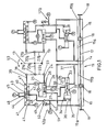
- Figure 1 is a schematic illustration of a servo system constructed in accordance with the invention for controlling the pitch of helicopter rotor blades, and
- Figure 2 is a schematic illustration of part of the system of Figure 1 and illustrating operational features in two failure cases.
- Referring now to Figure 1, a moving
body control jack 11 is operationally connected to duplicatedservo control circuits control stick 13. - The
control jack 11 comprises abody 14 formed with separated, longitudinally alignedchambers 15. Apiston 16 is located in eachchamber 15, thepistons 16 being interconnected by arod 17 and earthed to aircraft structure as indicated at 18. Each of thepistons 16 subdivides itsrespective chamber 15 intochambers -
Control stick 13 is pivotally attached to structure at 19 and is connected byrods pivotal attachments input levers attachment 19 comprises thebody 14 ofcontrol jack 11. - The remaining parts of each of the
control circuits left hand circuit 12a only. In the drawings, the letters P and R denote hydraulic pressure supplies and hydraulic return connections respectively. - One end of
lever 22a is connected throughpivotal attachment 23 to an end of arod 24 protruding axially from an end of amain spool valve 25. The rod carries twolands 26 in a chamber of thevalve 25, the axial position of thelands 26 serving to control the flow of pressurised hydraulic fluid from a pressure source tooutput conduits Conduits chambers chamber 15 ofcontrol jack 11. - A
branch conduit 29 connectsconduit 27 to achamber 30 formed in a by-pass valve 31 between two spaced-apart lands piston head 34 having a larger diameter than that of thelands coil spring 35 is located in achamber 36 formed on the side of thepiston head 34 opposite to that which carries thelands branch conduit 37 connectsconduit 28 also to thechamber 30, but at a position axially spaced from the connection ofconduit 29, for a purpose to be explained. - The other end of
lever 22a is connected throughpivotal attachment 38 to arod 39 protruding axially from one end of a break-outvalve 40 having aninternal chamber 41. Therod 39 carries afixed boss 42 between two slidinglands input conduit 45 and anoutput conduit 46. Acoil spring 47 is located in each end ofchamber 41 and forces thelands chamber 41 and in abutment with astop 48 provided on the inner wall ofchamber 41 -
Conduit 46 is filled with hydraulic fluid and connected tochamber 36 of by-pass valve 31. Anon-return valve 49 is fitted inconduit 46 and abranch conduit 50 downstream ofnon-return valve 49 includes aflow restrictor 51 and apressure switch indicator 52. - In normal operation of the control system, the force of
springs 47 in break-outvalve 40 maintains thesliding lands central stop 48, thereby acting throughfixed boss 42 to retain therod 39 in the position illustrated. Theconnection 38 thereby acts as a fixed pivot. - Thus, movement of
control stick 13 througharc 53 is transmitted throughrod 20a topivot input lever 22a about a fixed pivot provided byconnection 38 to adjust the position oflands 26 of themain spool valve 25 through therod 24. Movement oflands 26 from the illustrated null position serves to connect the supply of pressurised hydraulic fluid to one of thechambers chamber 15 ofcontrol jack 11, thereby moving the body ofjack 11 due to reaction with thefixed piston 16. The preferred embodiment, withattachment 19 comprising thebody 14 ofcontrol jack 11, provides an automatic feedback facility that is proportional to the input signal. - The pressurised fluid supply to by-
pass valve 31 acts on the surface area ofland 33 which overcomes the force ofspring 35 acting on the larger surface area ofpiston 34 to retain thelands branch conduits - Movement of the body of
jack 11 is transmitted through connecting means (not shown) to adjust the pitch of the helicopter rotor blades. It will be understood that the described control function is duplicated incontrol circuit 12b. - Figure 2 illustrates operation of
control circuit 12a in the event of a malfunction caused by sticking of themain spool valve 25. Two failure cases will be described; namely, a case in which the main spool valve sticks with thelands 26 in the null position indicated in full line in Figure 2, and a case in which thelands 26 stick in a position other than the null position as indicated in broken line in Figure 2. - It will be apparent that both conditions result in a fixing of the
connection 23 which, it will be remembered, in normal operation is capable of movement to adjust the position oflands 26. Thus, in a failure case,connection 23 becomes the fixed pivot and movement ofcontrol stick 13 acts torock input lever 22a about this pivot to cause axial movement ofrod 39 of break-outvalve 40. - Therefore, initial movement of the
control stick 13 subsequent to a failure ofspool valve 25 moves thesliding rod 39 of the failedcircuit 12a which acts throughfixed boss 42 to move one of thesliding lands spring 47 so as to uncover one of the ends of bifurcatedconduit 45. Hydraulic pressure is now admitted to the portion ofchamber 41 between thelands lands springs 47 to move thesliding lands stop 48 and by equal amounts, and to maintain the axial spacing between thelands - The axial spacing automatically established between the
lands 43 and.44 of break-outvalve 40 provides freedom of movement for thesliding rod 39 thereby effectively isolating the break-outvalve 40 of the failed ciruit from further movements of the control stick, with the result that thevalve 40 does not impose undesirable loadings on thecontrol stick 13 which is therefore free to maintain control through the remainingoperational circuit 12b. - Pressurised hydraulic fluid now flows through
conduit 46 intochamber 36 of by-pass valve 31, and due to the larger area if the head of thepiston 34, overcomes the pressure on the surface ofland 33 to move thelands chamber 30 of by-pass valve 31 betweenbranch conduits - In the case of failure with
lands 26 ofmain spool valve 25 stuck in the null position, this means that an open circuit is established betweenchambers chamber 15 ofcontrol jack 11 served bycircuit 12a so as to provide no restriction to movement of the body ofcontrol jack 11 by continued operation ofcontrol circuit 12b, which may thus function in the normal mode hereinbefore described in order to maintain control of thejack 11 to maintain an essential flight control system. - In the second failure case to be considered, with the spool valve stuck with its
lands 26 in the positions shown in broken lines, operation of the break-outvalve 40 and by-pass valve 31 is identical to that previously described. In this case, because of the offset position of the spool valve, pressurised hydraulic fluid will be supplied through themain spool valve 25 andconduit 28 tochamber 15b of therelevant chamber 15 ofcontrol jack 11; however, due to the open circuit established by operation of the by-pass valve 31, this pressure will equalise in both ofchambers circuit 12a provides no restraint to normal operation ofcircuit 12b by which an essential control function is maintained. - Thus, the present invention provides a servo system which functions automatically in the event of a failure of the main spool valve in one of the duplex servo control circuits. Furthermore, apart from the initial load required to actuate the isolating means in the break-out
valve 40 of the failed circuit by a subsequent movement of thecontrol stick 13, the system ensures that no forces emanate from the failed circuit to hinder continued control by the remaining operational circuit. - Whilst one embodiment of the invention has been described and illustrated it will be apparent that many modifications can be made without departing from the scope of the invention, as defined in the appended claims. For example, the individual servo control circuits can be used independantly in which case the invention serves to automatically isolate the circuit in the event of a failure.
Claims (12)
1. A servo system (11) having a servo control circuit (12a, 12b) adapted to control the flow of pressurised fluid to a hydraulic control jack (15), the control circuit including a main spool valve (25) for controlling the flow of pressurised fluid to chambers (15a, 15b) at each side of a piston (16) in the jack in response to movement of a control means (13), a break-out valve (40) operative in the event of a failure of the spool valve and in response to a subsequent movement of the control means to connect a source of pressurised fluid to operate a by-pass valve (31) to open a circuit between the chambers of the jack.
2. A servo system as claimed in Claim 1,wherein the break-out valve includes isolating means (42, 43, 44, 48) adapted to isolate the valve from subsequent movements of the control means.
3. A servo system as claimed in Claim 2, wherein the isolating means includes a boss (42) located in a chamber (41) of the break-out valve and operatively associated with the control means, a sliding land (43, 44) located at each side of the boss, spring means (47) normally operative to force the lands into contact with opposed surfaces of the boss and with a fixed abutment (48) inside the chamber, two pressurised fluid inlet conduits (45) opening into the chamber so as to be obturated by the respective lands during normal operation of the system, and an outlet conduit (46) opening into the chamber between the lands and operatively connected to the by-pass valve.
4. A servo system as claimed in Claim 3, wherein said boss is located intermediate the ends of an axially movable rod (39) protruding from one end of the chamber of the break-out valve for pivotal connection to the control means.
5. A servo system as claimed in Claim 3 or Claim 4, wherein the outlet conduit connects to a chamber (36) at one side of a piston head (34) of the by-pass valve, the piston head carrying a spool having spaced-apart lands (32, 33) controlling an interconnection between the chambers of the control jack.
6. A servo system as claimed in Claim 5, wherein a coil spring (35) acts on the piston head in the same sense as pressurised fluid from the break-out valve outlet conduit and is opposed by pressurised fluid acting on a reduced diameter of one of the lands.
7. A servo system as claimed in any one of Claims 3 to 6, wherein the break-out valve outlet conduit incorporates a non-return valve (41).
8. A servo system as claimed in any one of Claims 3 to 7, and including a pressure switch indicator (52) adapted to provide an indication of fluid pressure in the break-out valve outlet conduit.
9. A servo system as claimed in any one of Claims 4 to 8, wherein the protruding end of the rod is pivotally connected to one end of a lever (22a, 22b) the other end of which is pivotally connected to an end of an operating rod (24) protruding from the spool valve, the control means being pivotally attached intermediate the ends of the lever.
10. A servo system as claimed in Claim 9?wherein the control means comprises a control rod (20a, 20b) pivotally earthed to a moving body (14) of the control jack.
11. A servo system as claimed in any preceding claim, wherein the control circuit is duplicated to maintain operation of the jack in the event of a failure in one of the control circuits.
12. A servo system (11) including duplex servo control circuits (12a, 12b) each adapted during operation to control the flow of pressurised fluid to a common hydraulic control jack (15), each circuit having a main spool valve (25) for controlling the flow of pressurised fluid to chambers (15a, 15b) at each side of a piston (16) in the jack in response to movement of a control means (13), a break-out valve (40) operative in the event of a failure of the spool valve and in response to a subsequent movement of the control means to connect a source of pressurised fluid to operate a by-pass valve (31) to open a circuit between the chambers of the jack served by the failed circuit whereby continuous control of the position of the jack is provided by the second circuit, the break-out valve including isolating means (42, 43, 44, 48) adapted to isolate the valve from subsequent movements of the control means. 13. In or for a helicopter powered flying control system, a servo system (11) including duplex servo control circuits (12a, 12b) each adapted during operation to control the position of a common hydraulic jack, each circuit having a main spool valve (25) for controlling the flow of pressurised fluid to chambers (15a, 15b) at each side of a piston (16) in the jack in response to movement of a control stick (13), a break-out valve (40) operative in the event of a failure of the spool valve and in response to a subsequent movement of the control stick to connect a source of pressurised fluid to operate a by-pass valve (31) to open a circuit between the chambers of the jack served by the failed circuit whereby continued control of the position of the jack is provided by the second circuito
Applications Claiming Priority (2)
| Application Number | Priority Date | Filing Date | Title |
|---|---|---|---|
| GB8119838 | 1981-06-26 | ||
| GB8119838 | 1981-06-26 |
Publications (1)
| Publication Number | Publication Date |
|---|---|
| EP0068728A1 true EP0068728A1 (en) | 1983-01-05 |
Family
ID=10522847
Family Applications (1)
| Application Number | Title | Priority Date | Filing Date |
|---|---|---|---|
| EP82303139A Withdrawn EP0068728A1 (en) | 1981-06-26 | 1982-06-16 | Servo system |
Country Status (1)
| Country | Link |
|---|---|
| EP (1) | EP0068728A1 (en) |
Cited By (7)
| Publication number | Priority date | Publication date | Assignee | Title |
|---|---|---|---|---|
| EP0137052A1 (en) * | 1983-09-07 | 1985-04-17 | Feinmechanische Werke Mainz GmbH | Checking device for duplicated flight controls |
| EP0152714A1 (en) * | 1984-01-09 | 1985-08-28 | AEROSPATIALE Société Nationale Industrielle | Aircraft flight control system |
| EP0546895A1 (en) * | 1991-12-11 | 1993-06-16 | AEROSPATIALE Société Nationale Industrielle | Reduced vulnerability device to control a helicopter rotor through a swashplate |
| EP0639499A1 (en) * | 1993-08-20 | 1995-02-22 | Lucas France | Servo control device of an aircraft flight control member |
| ES2156497A1 (en) * | 1998-06-23 | 2001-06-16 | Turbo Propulsores Ind | Piston main servo-actuation system for use in global servo-actuation system, has hydromechanic self-contained failure detection device working with hydraulic fluid |
| EP3128216A1 (en) * | 2015-08-07 | 2017-02-08 | Claverham Limited | Hydraulic valve |
| US20210139134A1 (en) * | 2019-11-09 | 2021-05-13 | Bell Textron Inc. | Hydraulic cylinder with matching bias |
Citations (5)
| Publication number | Priority date | Publication date | Assignee | Title |
|---|---|---|---|---|
| FR2006276A1 (en) * | 1968-04-16 | 1969-12-26 | Automotive Prod Co Ltd | |
| DE1601713B2 (en) * | 1967-12-22 | 1971-09-02 | Dormer AG, 7990 Friedrichshafen | CONTROL AND CONTROL DEVICES ON SERVO CONTROLS |
| GB1306710A (en) * | 1970-09-22 | 1973-02-14 | Mainz Gmbh Feinmech Werke | Hydraulic and pneumatic control systems |
| GB1327393A (en) * | 1969-10-15 | 1973-08-22 | Automotive Prod Co Ltd | Fluid pressure control systems |
| GB1497594A (en) * | 1974-10-23 | 1978-01-12 | Messerschmitt Boelkow Blohm | Hydraulic servodrive |
-
1982
- 1982-06-16 EP EP82303139A patent/EP0068728A1/en not_active Withdrawn
Patent Citations (5)
| Publication number | Priority date | Publication date | Assignee | Title |
|---|---|---|---|---|
| DE1601713B2 (en) * | 1967-12-22 | 1971-09-02 | Dormer AG, 7990 Friedrichshafen | CONTROL AND CONTROL DEVICES ON SERVO CONTROLS |
| FR2006276A1 (en) * | 1968-04-16 | 1969-12-26 | Automotive Prod Co Ltd | |
| GB1327393A (en) * | 1969-10-15 | 1973-08-22 | Automotive Prod Co Ltd | Fluid pressure control systems |
| GB1306710A (en) * | 1970-09-22 | 1973-02-14 | Mainz Gmbh Feinmech Werke | Hydraulic and pneumatic control systems |
| GB1497594A (en) * | 1974-10-23 | 1978-01-12 | Messerschmitt Boelkow Blohm | Hydraulic servodrive |
Cited By (12)
| Publication number | Priority date | Publication date | Assignee | Title |
|---|---|---|---|---|
| EP0137052A1 (en) * | 1983-09-07 | 1985-04-17 | Feinmechanische Werke Mainz GmbH | Checking device for duplicated flight controls |
| EP0152714A1 (en) * | 1984-01-09 | 1985-08-28 | AEROSPATIALE Société Nationale Industrielle | Aircraft flight control system |
| EP0546895A1 (en) * | 1991-12-11 | 1993-06-16 | AEROSPATIALE Société Nationale Industrielle | Reduced vulnerability device to control a helicopter rotor through a swashplate |
| FR2684953A1 (en) * | 1991-12-11 | 1993-06-18 | Aerospatiale | REDUCED VULNERABILITY DEVICE FOR CONTROLLING A HELICOPTER ROTOR BY CYCLIC PLATFORMS. |
| US5310315A (en) * | 1991-12-11 | 1994-05-10 | Aerospatiale Societe Nationale Industrielle | Low-vulnerability device for the control of helicopter rotor by cyclic plates |
| EP0639499A1 (en) * | 1993-08-20 | 1995-02-22 | Lucas France | Servo control device of an aircraft flight control member |
| FR2709110A1 (en) * | 1993-08-20 | 1995-02-24 | Lucas Air Equipement | Servo-control device of an aircraft flight control member. |
| US5600220A (en) * | 1993-08-20 | 1997-02-04 | Lucas France | System for servo-controlling an aircraft flight control member |
| ES2156497A1 (en) * | 1998-06-23 | 2001-06-16 | Turbo Propulsores Ind | Piston main servo-actuation system for use in global servo-actuation system, has hydromechanic self-contained failure detection device working with hydraulic fluid |
| EP3128216A1 (en) * | 2015-08-07 | 2017-02-08 | Claverham Limited | Hydraulic valve |
| US10036408B2 (en) | 2015-08-07 | 2018-07-31 | Claverham Ltd. | Hydraulic valve |
| US20210139134A1 (en) * | 2019-11-09 | 2021-05-13 | Bell Textron Inc. | Hydraulic cylinder with matching bias |
Similar Documents
| Publication | Publication Date | Title |
|---|---|---|
| EP1182134B1 (en) | Hydraulic control system for a trim surface | |
| EP3222520B1 (en) | Local backup hydraulic actuator for aircraft control systems | |
| US5897293A (en) | Counterweighted propeller control system | |
| EP3543115B1 (en) | Distributed trailing edge wing flap systems | |
| JP7245643B2 (en) | Distributed trailing edge wing flap system | |
| US6206329B1 (en) | Process and device for the control of the rudder of an aircraft | |
| US4333387A (en) | Anti-jam hydraulic servo valve | |
| EP0311276B1 (en) | Bladed rotor assemblies | |
| EP0068728A1 (en) | Servo system | |
| EP1802940B1 (en) | Mechanical flight control auxiliary power assist system | |
| US7890222B1 (en) | Mechanical flight control auxiliary power assist system | |
| US3527143A (en) | Control systems | |
| US2950703A (en) | Manual and automatic hydraulic servomechanism | |
| US3554084A (en) | Redundant force summing servo unit | |
| US3034483A (en) | Hydraulic servomotor | |
| US3358565A (en) | Redundant actuator | |
| US4138088A (en) | Device for controlling hydraulic motors | |
| US2956408A (en) | Hydraulic flying control systems for aircraft | |
| US3143042A (en) | Electro-hydraulic servomotor | |
| US2988307A (en) | Flying control systems for aircraft | |
| EP4306810A1 (en) | Main control valve with integrated hydraulic scas | |
| RU2230944C2 (en) | Redundant electrohydraulic servo drive | |
| EP0115925A1 (en) | Control actuation system including staged direct drive valve with fault control | |
| JPS63297802A (en) | Neutral position resetting device for servoactuator | |
| Honey | Developments in aircraft power flying control hydraulics |
Legal Events
| Date | Code | Title | Description |
|---|---|---|---|
| PUAI | Public reference made under article 153(3) epc to a published international application that has entered the european phase |
Free format text: ORIGINAL CODE: 0009012 |
|
| AK | Designated contracting states |
Designated state(s): DE FR GB IT |
|
| STAA | Information on the status of an ep patent application or granted ep patent |
Free format text: STATUS: THE APPLICATION IS DEEMED TO BE WITHDRAWN |
|
| 18D | Application deemed to be withdrawn |
Effective date: 19831211 |
|
| RIN1 | Information on inventor provided before grant (corrected) |
Inventor name: BRAMMER, PETER ARTHUR HENRY |