EP3128214A2 - Hydraulic actuator with spring return - Google Patents
Hydraulic actuator with spring return Download PDFInfo
- Publication number
- EP3128214A2 EP3128214A2 EP15770239.0A EP15770239A EP3128214A2 EP 3128214 A2 EP3128214 A2 EP 3128214A2 EP 15770239 A EP15770239 A EP 15770239A EP 3128214 A2 EP3128214 A2 EP 3128214A2
- Authority
- EP
- European Patent Office
- Prior art keywords
- spring
- actuator
- hydraulic actuator
- spring return
- inert material
- Prior art date
- Legal status (The legal status is an assumption and is not a legal conclusion. Google has not performed a legal analysis and makes no representation as to the accuracy of the status listed.)
- Withdrawn
Links
Images


Classifications
-
- F—MECHANICAL ENGINEERING; LIGHTING; HEATING; WEAPONS; BLASTING
- F16—ENGINEERING ELEMENTS AND UNITS; GENERAL MEASURES FOR PRODUCING AND MAINTAINING EFFECTIVE FUNCTIONING OF MACHINES OR INSTALLATIONS; THERMAL INSULATION IN GENERAL
- F16K—VALVES; TAPS; COCKS; ACTUATING-FLOATS; DEVICES FOR VENTING OR AERATING
- F16K31/00—Actuating devices; Operating means; Releasing devices
- F16K31/12—Actuating devices; Operating means; Releasing devices actuated by fluid
- F16K31/122—Actuating devices; Operating means; Releasing devices actuated by fluid the fluid acting on a piston
- F16K31/1221—Actuating devices; Operating means; Releasing devices actuated by fluid the fluid acting on a piston one side of the piston being spring-loaded
-
- F—MECHANICAL ENGINEERING; LIGHTING; HEATING; WEAPONS; BLASTING
- F16—ENGINEERING ELEMENTS AND UNITS; GENERAL MEASURES FOR PRODUCING AND MAINTAINING EFFECTIVE FUNCTIONING OF MACHINES OR INSTALLATIONS; THERMAL INSULATION IN GENERAL
- F16K—VALVES; TAPS; COCKS; ACTUATING-FLOATS; DEVICES FOR VENTING OR AERATING
- F16K31/00—Actuating devices; Operating means; Releasing devices
- F16K31/12—Actuating devices; Operating means; Releasing devices actuated by fluid
-
- F—MECHANICAL ENGINEERING; LIGHTING; HEATING; WEAPONS; BLASTING
- F15—FLUID-PRESSURE ACTUATORS; HYDRAULICS OR PNEUMATICS IN GENERAL
- F15B—SYSTEMS ACTING BY MEANS OF FLUIDS IN GENERAL; FLUID-PRESSURE ACTUATORS, e.g. SERVOMOTORS; DETAILS OF FLUID-PRESSURE SYSTEMS, NOT OTHERWISE PROVIDED FOR
- F15B15/00—Fluid-actuated devices for displacing a member from one position to another; Gearing associated therewith
- F15B15/08—Characterised by the construction of the motor unit
- F15B15/14—Characterised by the construction of the motor unit of the straight-cylinder type
- F15B15/1423—Component parts; Constructional details
- F15B15/1476—Special return means
-
- F—MECHANICAL ENGINEERING; LIGHTING; HEATING; WEAPONS; BLASTING
- F15—FLUID-PRESSURE ACTUATORS; HYDRAULICS OR PNEUMATICS IN GENERAL
- F15B—SYSTEMS ACTING BY MEANS OF FLUIDS IN GENERAL; FLUID-PRESSURE ACTUATORS, e.g. SERVOMOTORS; DETAILS OF FLUID-PRESSURE SYSTEMS, NOT OTHERWISE PROVIDED FOR
- F15B15/00—Fluid-actuated devices for displacing a member from one position to another; Gearing associated therewith
- F15B15/20—Other details, e.g. assembly with regulating devices
- F15B15/24—Other details, e.g. assembly with regulating devices for restricting the stroke
-
- E—FIXED CONSTRUCTIONS
- E21—EARTH DRILLING; MINING
- E21B—EARTH DRILLING, e.g. DEEP DRILLING; OBTAINING OIL, GAS, WATER, SOLUBLE OR MELTABLE MATERIALS OR A SLURRY OF MINERALS FROM WELLS
- E21B34/00—Valve arrangements for boreholes or wells
- E21B34/02—Valve arrangements for boreholes or wells in well heads
- E21B34/04—Valve arrangements for boreholes or wells in well heads in underwater well heads
Definitions
- the present invention refers to a hydraulic actuator with spring return for operating submerged valves in a platform of petroleum production located in a manifold structure or in a wet Christmas tree.
- the current technology for corrosion protection of the actuator spring is based on the immersion of the spring in a water or oil-based corrosion inhibitor fluid. A series of extra components and procedures is necessary for performing this strategy.
- a housing for spring and for corrosion inhibitor fluid contention is necessary.
- a second housing with variable inner volume connected to the spring housing is necessary to promote the corrosion inhibitor fluid contention when with volumetric change due to temperature variations.
- the connection between these two housings is performed through a tubing that is also necessary.
- the tubing connecting two housings is equipped with a relief valve to the environment. This system is called compensation.
- the tubing of the compensation system may be interconnected to the control system to enable the corrosion inhibitor fluid replacement.
- the actuator spring is made from selected material inert to corrosion of seawater and resistant to submarine environment such that the protection of the corrosion inhibitor fluid and all previous devices and procedures are no longer needed.
- the spring will be exposed to seawater, it will not be necessary to have a housing for containing the corrosion inhibitor fluid, not all sealing elements; and the connection with this part to the compensation system is not yet necessary.
- spring means any mean storing energy through the deformation of one or more solid elements.
- the hydraulic actuator with spring return object of the invention, operates with spring (2) directly exposed to seawater without the need of a special housing (15) for the said spring (2), dismissing, as noted in the figure of the state of the art, besides the housing (15), compensation system (16, 17, 18 e 19), corrosion inhibitor fluid (13), system of inhibitor fluid replacement (12) and also sealing means (14).
- the constructive characteristics of the pressure actuator according to the present invention, have special aspects and much less complex than the actuators known in the current technique.
- the spring (2) of the actuator (1) of the present invention manufactured in inert material, it is assembled in an exposed manner to seawater, in a moving stopper (3) coupled to actuator rod (5) by any fixation mean known, such as screw key, weld, etc.
- the said moving stopper (3) is in sliding contact with a stabilizer extension (4) of the rod (5), through two or more guide tears (20).
- the actuator has one control fluid inlet (8) in the piston chamber (7), the fluid acting in a piston (6) by both sides, promoting the spring compression and expansion, which causes the longitudinal displacement of the actuator rod (5) and consequently the valve closure and opening (11), this fixed to the actuator by flange (9) and connected to the said piston by valve rod (10).
- the pressure actuator of the invention may have springs with different constructive concepts, such as helical spring, ring spring, plate spring, etc., as well as any type of inert materials, in this way not overcoming or modifying its inventive concept.
Landscapes
- Engineering & Computer Science (AREA)
- General Engineering & Computer Science (AREA)
- Mechanical Engineering (AREA)
- Physics & Mathematics (AREA)
- Fluid Mechanics (AREA)
- Actuator (AREA)
Abstract
Description
- The present invention refers to a hydraulic actuator with spring return for operating submerged valves in a platform of petroleum production located in a manifold structure or in a wet Christmas tree.
- One of the factors that most damage equipment and affect its operational means in the submarine environment is corrosion due to aggressive means wherein seawater is constituted.
- The submarine hydraulic actuators existing on the market today with return characteristics in case of failure, store the energy for the return in a metallic spring. The systems of corrosion protection usually employed in submarine equipment such as coatings that isolate the material from contact with seawater, and cathodic protection; they cannot be applied to the actuator spring because the deformation of the spring prevents the application of coating and the metal used for manufacturing this spring is not compatible with the system of cathodic protection as it is a material subject to embrittlement due to hydrogen produced migration by chemical reaction of the cathodic protection.
- The current technology for corrosion protection of the actuator spring is based on the immersion of the spring in a water or oil-based corrosion inhibitor fluid. A series of extra components and procedures is necessary for performing this strategy.
- Other aspect noted in the means currently employed, is that is necessary a housing for spring and for corrosion inhibitor fluid contention. A second housing with variable inner volume connected to the spring housing is necessary to promote the corrosion inhibitor fluid contention when with volumetric change due to temperature variations. The connection between these two housings is performed through a tubing that is also necessary. To protect the system from improper pressure increase due to thermal expansion of the fluid, the tubing connecting two housings is equipped with a relief valve to the environment. This system is called compensation. Several seal elements are present in the system for having the corrosion inhibitor fluid. The tubing of the compensation system may be interconnected to the control system to enable the corrosion inhibitor fluid replacement.
- Other drawback found in current systems employed is that the metallic spring must be wrapped in a sealed package having sequestering material of oxygen to prevent corrosion during its storage. After assembling the spring in the actuator, the filling of corrosion inhibitor fluid, the spring housing chamber must pass through a long flow process of high flow rate of the inhibitor fluid corrosion to remove contaminant particles that could clog the tubing holes of the compensation system.
- In these kinds of spring actuators, during the storage of these already assembled and after its assembly in the end equipment, constant monitoring and replacement of the corrosion inhibitor fluid in the reservoirs is needed. It is common in the industry the inflow of seawater when the actuator is submerged or air while still on the surface, causing corrosion of the spring despite all barriers and precautions against corrosion.
- According to the drawbacks mentioned above, it is noted that in the hydraulic actuators with spring return to operate submerged valves designed so far, they have complex construction characteristics due to the corrosion problem of the spring.
- It is object of the invention to eliminate or minimize these prior art problems by designing a pressure actuator with spring that due to the constitution of the spring material, may have its operation with the spring exposed to seawater, and present proper constructive characteristics, simpler and more efficient. Thus the actuator spring is made from selected material inert to corrosion of seawater and resistant to submarine environment such that the protection of the corrosion inhibitor fluid and all previous devices and procedures are no longer needed. As the spring will be exposed to seawater, it will not be necessary to have a housing for containing the corrosion inhibitor fluid, not all sealing elements; and the connection with this part to the compensation system is not yet necessary.
- Additionally, it is the object of the present invention to eliminate all preservation procedures of the spring in inert environment of oxygen, of spring housing cleaning and corrosion inhibitor fluid replacement.
- The present invention will be described in the following with reference to the attached figures, which in a schematic and non-limitative to its scope manner, represent:
-
Figure 1 illustrates a cross section view of a hydraulic actuator with spring return, according to the prior art; -
Figure 2 illustrates a cross section view of the hydraulic actuator with spring return, according to the present invention; -
Figure 3 illustrates a detail of the stabilizer extension provided with guide tears, according to the present invention; -
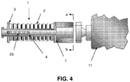
Figure 4 illustrates a schematic view in partial cut (a - b), longitudinal of other constructive embodiment of the hydraulic actuator to use with springs of plate or ring, according to the present invention. - In the present description, the term "spring" means any mean storing energy through the deformation of one or more solid elements.
- The hydraulic actuator with spring return, object of the invention, operates with spring (2) directly exposed to seawater without the need of a special housing (15) for the said spring (2), dismissing, as noted in the figure of the state of the art, besides the housing (15), compensation system (16, 17, 18 e 19), corrosion inhibitor fluid (13), system of inhibitor fluid replacement (12) and also sealing means (14). Thus, the constructive characteristics of the pressure actuator, according to the present invention, have special aspects and much less complex than the actuators known in the current technique.
- By being the spring (2) of the actuator (1) of the present invention manufactured in inert material, it is assembled in an exposed manner to seawater, in a moving stopper (3) coupled to actuator rod (5) by any fixation mean known, such as screw key, weld, etc. The said moving stopper (3) is in sliding contact with a stabilizer extension (4) of the rod (5), through two or more guide tears (20).
- In operation, the actuator has one control fluid inlet (8) in the piston chamber (7), the fluid acting in a piston (6) by both sides, promoting the spring compression and expansion, which causes the longitudinal displacement of the actuator rod (5) and consequently the valve closure and opening (11), this fixed to the actuator by flange (9) and connected to the said piston by valve rod (10).
- The pressure actuator of the invention, as here defined, may have springs with different constructive concepts, such as helical spring, ring spring, plate spring, etc., as well as any type of inert materials, in this way not overcoming or modifying its inventive concept.
Claims (7)
- Hydraulic actuator with spring return, of a type comprising a system with control fluid (8) acting in a piston (6) coupled, on one side, to a rod (10) of valve (11) through the flange (9) and, on the other side, to an actuator rod (5), where a spring (2) of the actuator is fitted into the piston chamber (7), wherein the spring (2) of inert material of the actuator (1) is assembled in direct contact with the seawater in a moving stopper (3) coupled by fixation special means to the actuator rod (5), and wherein the said moving stopper (3) is in sliding contact with a stabilizer extension (4) of the actuator rod (5), through two or more guide tears (20).
- Hydraulic actuator with spring return according to claim 1, wherein the inert material of the spring (2) comprises a carbon fiber composite material.
- Hydraulic actuator with spring return according to claims 1 or 2, wherein the spring of inert material is coil-type spring.
- Hydraulic actuator with spring return according to claims 1 or 2, wherein the spring of inert material is ring-type spring.
- Hydraulic actuator with spring return according to claims 1 or 2, wherein the spring of inert material is plate-type spring.
- Hydraulic actuator with spring return according to claim 1, wherein the fixation means of the moving stopper (3) with the actuator rod (5) comprises screws, keys and welds.
- Hydraulic actuator with spring return according to claims 4 or 5, wherein the moving stopper (3) has the shape of a flat disk.
Applications Claiming Priority (2)
| Application Number | Priority Date | Filing Date | Title |
|---|---|---|---|
| BR102014007557A BR102014007557A2 (en) | 2014-03-28 | 2014-03-28 | spring return hydraulic actuator |
| PCT/BR2015/050033 WO2015143524A2 (en) | 2014-03-28 | 2015-03-25 | Hydraulic actuator with spring return |
Publications (2)
| Publication Number | Publication Date |
|---|---|
| EP3128214A2 true EP3128214A2 (en) | 2017-02-08 |
| EP3128214A4 EP3128214A4 (en) | 2018-04-04 |
Family
ID=54196508
Family Applications (1)
| Application Number | Title | Priority Date | Filing Date |
|---|---|---|---|
| EP15770239.0A Withdrawn EP3128214A4 (en) | 2014-03-28 | 2015-03-25 | Hydraulic actuator with spring return |
Country Status (4)
| Country | Link |
|---|---|
| US (1) | US20170175923A1 (en) |
| EP (1) | EP3128214A4 (en) |
| BR (1) | BR102014007557A2 (en) |
| WO (1) | WO2015143524A2 (en) |
Families Citing this family (2)
| Publication number | Priority date | Publication date | Assignee | Title |
|---|---|---|---|---|
| US10954746B2 (en) | 2016-07-27 | 2021-03-23 | Fmc Technologies, Inc. | Ultra-compact subsea tree |
| DE102020204754A1 (en) * | 2020-04-15 | 2021-10-21 | Festo Se & Co. Kg | Valve |
Family Cites Families (12)
| Publication number | Priority date | Publication date | Assignee | Title |
|---|---|---|---|---|
| US3379405A (en) * | 1966-01-03 | 1968-04-23 | Acf Ind Inc | Valve |
| US4230140A (en) * | 1979-01-15 | 1980-10-28 | Under Sea Industries, Inc. | Environmental first stage scuba regulator |
| US4311297A (en) * | 1980-04-04 | 1982-01-19 | Exxon Production Research Company | Pressure insensitive valve |
| US4650151A (en) * | 1983-01-10 | 1987-03-17 | Fmc Corporation | Subsea gate valve actuator with external manual override and drift adjustment |
| SE509643C2 (en) * | 1996-03-06 | 1999-02-15 | Pos Line Ab | Single acting pneumatic piston-cylinder unit |
| US6167909B1 (en) * | 1999-09-28 | 2001-01-02 | Tactair Fluid Controls, Inc. | Corrosion and contaminant resistant slide valve |
| US6474359B1 (en) * | 2000-03-08 | 2002-11-05 | National Coupling Company, Inc. | Undersea hydraulic coupling member |
| US6227245B1 (en) * | 2000-09-28 | 2001-05-08 | National Coupling Company Inc. | Undersea hydraulic coupling with internal guard for flow port |
| US6637459B1 (en) * | 2002-08-30 | 2003-10-28 | National Coupling Company, Inc. | Undersea hydraulic coupling member with external port guard |
| DE102006009273A1 (en) * | 2006-02-28 | 2007-08-30 | BSH Bosch und Siemens Hausgeräte GmbH | Refrigeration device especially a cooling- and/or refrigeration cabinet, has kinetic energy of compressor piston stored with intermediate storage medium during intermittent oscillating movement by compression of gaseous fluid |
| US7762525B2 (en) * | 2007-03-15 | 2010-07-27 | National Coupling Company, Inc. | Pressure-balanced undersea hydraulic coupling |
| US8905141B2 (en) * | 2011-12-13 | 2014-12-09 | Hydril Usa Manufacturing Llc | Subsea operating valve connectable to low pressure recipient |
-
2014
- 2014-03-28 BR BR102014007557A patent/BR102014007557A2/en not_active IP Right Cessation
-
2015
- 2015-03-25 US US15/300,124 patent/US20170175923A1/en not_active Abandoned
- 2015-03-25 EP EP15770239.0A patent/EP3128214A4/en not_active Withdrawn
- 2015-03-25 WO PCT/BR2015/050033 patent/WO2015143524A2/en active Application Filing
Also Published As
| Publication number | Publication date |
|---|---|
| EP3128214A4 (en) | 2018-04-04 |
| US20170175923A1 (en) | 2017-06-22 |
| BR102014007557A2 (en) | 2016-04-12 |
| WO2015143524A2 (en) | 2015-10-01 |
| WO2015143524A3 (en) | 2016-01-21 |
Similar Documents
| Publication | Publication Date | Title |
|---|---|---|
| US8439080B2 (en) | Pressure compensator | |
| US20150034185A1 (en) | Multi-Port Valve Device with Dual Directional Strainer | |
| US20130319220A1 (en) | Fluid End Reinforced With Abrasive Resistant Insert, Coating Or Lining | |
| RU2471959C1 (en) | Two-stage underwater actuating mechanisms | |
| US20200408340A1 (en) | O-ring seal system for metal, thermoplastic and fiber reinforced plastic flanges | |
| US20160215913A1 (en) | Pressure compensator for subsea device | |
| EP3128214A2 (en) | Hydraulic actuator with spring return | |
| JP6505139B2 (en) | Advanced pressure protection system (HIPPS) for fluid lines | |
| MXPA02009610A (en) | Subsea chemical injection pump. | |
| US20110123377A1 (en) | Piston compressor with no-load operation valve | |
| RU164371U1 (en) | LATCH WITH COMPENSATION CAMERA | |
| AU2018401713B2 (en) | Well annulus fluid expansion storage device | |
| US20190249806A1 (en) | Method of modernizing a fluid transport flexible conduit line, end fittings joint and interconnection module | |
| RU2764323C1 (en) | Apparatus for equalising the pressure in a sealed body of an autonomous apparatus | |
| US20180156342A1 (en) | Bi-directional flow control valve | |
| RU2714714C1 (en) | Safety valve (versions) | |
| US20220412189A1 (en) | Centrifugal pump for heating fluid by eddy current, and subsea tool for heating fluid by eddy current | |
| EP2971799B1 (en) | Piston with sealing pressed by pressure of an internal piston chamber | |
| CN205956421U (en) | Valve door part that leakproofness is high | |
| CN211009954U (en) | Adaptive stop valve | |
| KR101657618B1 (en) | Apparatus for preventing rust of hydraulic actuator for power plant | |
| KR200476972Y1 (en) | Control valve with high-temperature and high-pressure valve seat | |
| CN212004330U (en) | Corrosion-resistant corrugated pipe gate valve | |
| CN211779216U (en) | Micro-pressure gas-liquid back pressure valve | |
| RU2364779C2 (en) | Safety valve |
Legal Events
| Date | Code | Title | Description |
|---|---|---|---|
| PUAI | Public reference made under article 153(3) epc to a published international application that has entered the european phase |
Free format text: ORIGINAL CODE: 0009012 |
|
| 17P | Request for examination filed |
Effective date: 20161027 |
|
| AK | Designated contracting states |
Kind code of ref document: A2 Designated state(s): AL AT BE BG CH CY CZ DE DK EE ES FI FR GB GR HR HU IE IS IT LI LT LU LV MC MK MT NL NO PL PT RO RS SE SI SK SM TR |
|
| AX | Request for extension of the european patent |
Extension state: BA ME |
|
| DAV | Request for validation of the european patent (deleted) | ||
| DAX | Request for extension of the european patent (deleted) | ||
| R17P | Request for examination filed (corrected) |
Effective date: 20161027 |
|
| A4 | Supplementary search report drawn up and despatched |
Effective date: 20180306 |
|
| RIC1 | Information provided on ipc code assigned before grant |
Ipc: F16F 1/366 20060101ALI20180228BHEP Ipc: F16K 31/122 20060101AFI20180228BHEP Ipc: F15B 15/14 20060101ALI20180228BHEP Ipc: F15B 13/10 20060101ALI20180228BHEP Ipc: F15B 20/00 20060101ALI20180228BHEP Ipc: F15B 15/24 20060101ALI20180228BHEP |
|
| STAA | Information on the status of an ep patent application or granted ep patent |
Free format text: STATUS: THE APPLICATION IS DEEMED TO BE WITHDRAWN |
|
| 18D | Application deemed to be withdrawn |
Effective date: 20191001 |