EP3128208A2 - Vehicle differential - Google Patents
Vehicle differential Download PDFInfo
- Publication number
- EP3128208A2 EP3128208A2 EP16182671.4A EP16182671A EP3128208A2 EP 3128208 A2 EP3128208 A2 EP 3128208A2 EP 16182671 A EP16182671 A EP 16182671A EP 3128208 A2 EP3128208 A2 EP 3128208A2
- Authority
- EP
- European Patent Office
- Prior art keywords
- ring gear
- protrusion
- differential
- rotational axis
- inner peripheral
- Prior art date
- Legal status (The legal status is an assumption and is not a legal conclusion. Google has not performed a legal analysis and makes no representation as to the accuracy of the status listed.)
- Granted
Links
Images




Classifications
-
- F—MECHANICAL ENGINEERING; LIGHTING; HEATING; WEAPONS; BLASTING
- F16—ENGINEERING ELEMENTS AND UNITS; GENERAL MEASURES FOR PRODUCING AND MAINTAINING EFFECTIVE FUNCTIONING OF MACHINES OR INSTALLATIONS; THERMAL INSULATION IN GENERAL
- F16H—GEARING
- F16H55/00—Elements with teeth or friction surfaces for conveying motion; Worms, pulleys or sheaves for gearing mechanisms
- F16H55/02—Toothed members; Worms
- F16H55/17—Toothed wheels
-
- F—MECHANICAL ENGINEERING; LIGHTING; HEATING; WEAPONS; BLASTING
- F16—ENGINEERING ELEMENTS AND UNITS; GENERAL MEASURES FOR PRODUCING AND MAINTAINING EFFECTIVE FUNCTIONING OF MACHINES OR INSTALLATIONS; THERMAL INSULATION IN GENERAL
- F16H—GEARING
- F16H48/00—Differential gearings
- F16H48/06—Differential gearings with gears having orbital motion
-
- F—MECHANICAL ENGINEERING; LIGHTING; HEATING; WEAPONS; BLASTING
- F16—ENGINEERING ELEMENTS AND UNITS; GENERAL MEASURES FOR PRODUCING AND MAINTAINING EFFECTIVE FUNCTIONING OF MACHINES OR INSTALLATIONS; THERMAL INSULATION IN GENERAL
- F16H—GEARING
- F16H48/00—Differential gearings
- F16H48/06—Differential gearings with gears having orbital motion
- F16H48/08—Differential gearings with gears having orbital motion comprising bevel gears
-
- F—MECHANICAL ENGINEERING; LIGHTING; HEATING; WEAPONS; BLASTING
- F16—ENGINEERING ELEMENTS AND UNITS; GENERAL MEASURES FOR PRODUCING AND MAINTAINING EFFECTIVE FUNCTIONING OF MACHINES OR INSTALLATIONS; THERMAL INSULATION IN GENERAL
- F16H—GEARING
- F16H48/00—Differential gearings
- F16H48/38—Constructional details
-
- F—MECHANICAL ENGINEERING; LIGHTING; HEATING; WEAPONS; BLASTING
- F16—ENGINEERING ELEMENTS AND UNITS; GENERAL MEASURES FOR PRODUCING AND MAINTAINING EFFECTIVE FUNCTIONING OF MACHINES OR INSTALLATIONS; THERMAL INSULATION IN GENERAL
- F16H—GEARING
- F16H48/00—Differential gearings
- F16H48/38—Constructional details
- F16H48/40—Constructional details characterised by features of the rotating cases
-
- F—MECHANICAL ENGINEERING; LIGHTING; HEATING; WEAPONS; BLASTING
- F16—ENGINEERING ELEMENTS AND UNITS; GENERAL MEASURES FOR PRODUCING AND MAINTAINING EFFECTIVE FUNCTIONING OF MACHINES OR INSTALLATIONS; THERMAL INSULATION IN GENERAL
- F16H—GEARING
- F16H55/00—Elements with teeth or friction surfaces for conveying motion; Worms, pulleys or sheaves for gearing mechanisms
- F16H55/02—Toothed members; Worms
- F16H55/08—Profiling
- F16H55/0886—Profiling with corrections along the width, e.g. flank width crowning for better load distribution
-
- F—MECHANICAL ENGINEERING; LIGHTING; HEATING; WEAPONS; BLASTING
- F16—ENGINEERING ELEMENTS AND UNITS; GENERAL MEASURES FOR PRODUCING AND MAINTAINING EFFECTIVE FUNCTIONING OF MACHINES OR INSTALLATIONS; THERMAL INSULATION IN GENERAL
- F16H—GEARING
- F16H57/00—General details of gearing
- F16H57/02—Gearboxes; Mounting gearing therein
- F16H57/037—Gearboxes for accommodating differential gearings
-
- F—MECHANICAL ENGINEERING; LIGHTING; HEATING; WEAPONS; BLASTING
- F16—ENGINEERING ELEMENTS AND UNITS; GENERAL MEASURES FOR PRODUCING AND MAINTAINING EFFECTIVE FUNCTIONING OF MACHINES OR INSTALLATIONS; THERMAL INSULATION IN GENERAL
- F16H—GEARING
- F16H48/00—Differential gearings
- F16H48/38—Constructional details
- F16H2048/385—Constructional details of the ring or crown gear
-
- F—MECHANICAL ENGINEERING; LIGHTING; HEATING; WEAPONS; BLASTING
- F16—ENGINEERING ELEMENTS AND UNITS; GENERAL MEASURES FOR PRODUCING AND MAINTAINING EFFECTIVE FUNCTIONING OF MACHINES OR INSTALLATIONS; THERMAL INSULATION IN GENERAL
- F16H—GEARING
- F16H55/00—Elements with teeth or friction surfaces for conveying motion; Worms, pulleys or sheaves for gearing mechanisms
- F16H55/02—Toothed members; Worms
- F16H55/17—Toothed wheels
- F16H2055/173—Crown gears, i.e. gears have axially arranged teeth
Definitions
- the present disclosure relates to a vehicle differential including a differential case with an opening, and more particularly to a technique for suppressing gear noise generated from a differential case.
- vehicle differentials there is one that has a differential case and a ring gear, of which the former is configured to rotate around one rotational axis, and has a peripheral wall housing a pair of side gears and pinion gears in mesh therewith, an annular ring gear mount protruding from the peripheral wall toward the outer peripheral side to allow the ring gear to be fixed thereto, and an opening formed so as to penetrate a part of the peripheral wall, and the latter is fitted on the outer side of the peripheral wall and has an annular shape centered on the rotational axis.
- the vehicle differential of Japanese Patent Application Publication No. 2011-106504 .
- the vehicle differential of JP 2011-106504 A transmits power, input into the annular ring gear fixed to the mount face of the annular ring gear mount, to a pair of left and right drive wheels that are respectively coupled to the pair of side gears, while allowing a rotational difference between the pair of side gears.
- the present disclosure provides a vehicle differential in which gear noise resulting from a variation in area of contact between the ring gear and the driving gear is reduced.
- a vehicle differential includes a pair of side gears, at least one pinion gear, a differential case, and an annular ring gear.
- the pinion gear meshes with the side gears.
- the differential case has a peripheral wall and houses the side gears and the pinion gear.
- the differential case includes at least one opening arranged through the peripheral wall.
- the differential case is configured to rotate around one rotational axis.
- the annular ring gear is fitted on the outer side of the peripheral wall of the differential case such that the central axis of the ring gear and the rotational axis coincide with each other.
- the annular ring gear includes at least one protrusion on an inner peripheral edge of the annular ring gear.
- a first protrusion among said at least one protrusion covers at least a part of a first one of said at least one opening in a view of along a penetration direction of said first opening.
- a 'penetration direction' is a radial direction along which the opening is made through the peripheral wall of the differential case.
- the first protrusion protrudes toward an inner side of said first opening in a radial direction of the rotational axis, as compared with a part of the inner peripheral edge of the ring gear that has no protrusion.
- the radial width of the part of the ring gear which extends within the angular range of said first opening is increased, and thereby, the rigidity of the ring gear is enhanced, so that gear noise due to a variation in area of contact between the ring gear and the driving gear is reduced.
- the protrusion of the ring gear protrudes toward the opening of the differential case, the protrusion does not add to the size of the assembly of the differential case and the ring gear.
- the facewidth of the ring gear in the radial direction of the rotational axis may be larger in the part with said first protrusion than in the other part without protrusion.
- the driving pinion meshes with the meshing teeth since it has an increased facewidth in the part with the protrusion of the ring gear, so that a decrease in area of contact between the ring gear and the driving pinion is prevented and the generation of gear noise is reduced.
- the durability of the ring gear can be enhanced, since an increase in input per unit area into the meshing teeth of the ring gear due to a decrease in area of contact with the driving pinion is prevented.
- an inner edge of the protrusion may be a straight surface, or a curved surface, or an inner edge of the protrusion may be defined by two straight surfaces.
- FIG. 1 is a perspective view showing a vehicle differential 10 (hereinafter referred to as the "differential 10") of one embodiment of the present disclosure, in a section passing through a rotational axis C1 of a differential case 26 and the centerline of a pinion pin 30.
- FIG. 2 is a perspective view showing a part of a section that passes through the rotational axis C1 of the differential case 26 of the differential 10 and is perpendicular to the centerline of the pinion pin 30.
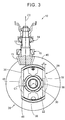
- FIG. 3 is a view of the differential 10 as seen in the direction of the rotational axis C1, including a view showing a section of a driving pinion 13 in mesh with a ring gear 28 and a driving pinion shaft 12.
- FIG. 4 is a perspective view of the differential 10.
- Meshing teeth 16 (shown in FIG. 6 and FIG. 7 ) formed in the ring gear 28, which is a hypoid gear, for example, are omitted in FIG. 1 to FIG. 4 .
- axles that are coupled to side gears 18 such that power can be transmitted thereto are not shown.
- the differential 10 includes the differential case 26 and the annular ring gear 28.
- the differential case 26 is configured to rotate around one rotational axis C1 and has: a substantially cylindrical peripheral wall 22 that houses the pair of side gears 18 facing each other on the rotational axis C1, and a pair of pinion gears 20 facing each other across the rotational axis C1 and in mesh respectively with the pair of side gears 18, such that each of the side gears 18 and the pinion gears 20 is rotatably supported; and an annular flange 24 that is integrally provided on the peripheral wall 22 so as to protrude from the outer peripheral surface of the peripheral wall 22 toward the outer peripheral side in a direction orthogonal to the rotational axis C1, and functions as a ring gear mount.
- the ring gear 28 is fixed to an annular mount face 27 that is one face of the flange 24. That is, the ring gear 28 is fitted on the outer side of the peripheral wall 22 such that the central axis of the ring gear 28 coincides with the rotational axis C1 of the differential case 26.
- Both ends of the pinion pin 30 that rotatably supports the pair of pinion gears 20 inside the differential case 26 are fixed at symmetrical points on the peripheral wall 22 in the direction of the rotational axis C1 such that the longitudinal direction of the pinion pin 30 is orthogonal to the rotational axis C1 of the ring gear 28.
- the differential case 26 further includes a pair of cylindrical bosses 32 that protrude from the peripheral wall 22 in directions away from each other along the direction of the rotational axis C1.
- One ends of the pair of axles (not shown) are respectively inserted into the bosses 32, and respectively coupled by spline fitting to the pair of side gears 18, which are provided across the pair of pinion gears 20 inside the differential case 26, such that power can be transmitted to the axles.
- the flange 24 protrudes toward the outer peripheral side from the outer peripheral surface of the peripheral wall 22 of the differential case 26 between the pinion pin 30 and the boss 32 in the direction of the rotational axis C1.
- the ring gear 28, in surface contact with the annular mount face 27 of the flange 24 on the side of the pinion pin 30, is fixed to the flange 24 with a plurality of (for example, 16) bolts 34 disposed at regular intervals in the circumferential direction.
- the differential case 26 has a pair of openings 36 each arranged through the differential case 26 at a part of the side surface of the peripheral wall 22.
- the pair of openings 36 are formed so as to locally cut out the side surface of the cylindrical peripheral wall 22 across the pinion pin 30.
- the differential 10 is provided, for example, on a power transmission path through which power from a vehicle driving source is transmitted to a pair of drive wheels, and includes the driving pinion shaft 12 coupled to a propeller shaft and the driving pinion 13 provided at one end of the driving pinion shaft 12.
- the driving pinion shaft 12 is supported through a first bearing 14 and a second bearing 15 on a housing (not shown) so as to be rotatable around a rotational axis C2.
- the rotational axis C2 of the driving pinion shaft 12 is located so that the pinion 13 meshes with the ring gear 28.
- the rotational axis C2 is at a right angle to but does not intersect with the rotational axis C1 of the ring gear 28; the driving pinion 13 and the ring gear 28 in mesh therewith constitute a hypoid gear pair.
- the differential 10 transmits power, inputted from the driving pinion 13 into the ring gear 28, to the pair of left and right axles that are respectively coupled to the pair of side gears 18, while allowing a rotational difference between the pair of side gears 18.
- FIG. 5 is a view of the ring gear 28 as seen in the direction of the rotational axis C1;
- FIG. 6 is a view of section VI-VI of FIG. 5 ;
- FIG. 7 is a view of section VII-VII of FIG. 5 .
- the annular ring gear 28 when seen in the direction of the rotational axis C1, has the plurality of meshing teeth 16 of a facewidth a on the conical surface between an inner peripheral edge 38 and an outer peripheral edge 40 on the opposite side from the side of the ring gear 28 in contact with the mount face 27 of the flange 24, and the meshing teeth 16 are in mesh with the meshing teeth of the driving pinion 13 having a smaller diameter than the ring gear 28.
- a plurality of columnar holes 42 with a female thread engaging with the bolt 34 are formed in the circumferential direction.
- the meshing teeth 16 formed on the conical surface of the ring gear 28 are omitted.
- the differential case 26 and the ring gear 28 may be assembled by welding instead of with bolts.
- the differential case 26 has the pair of openings 36 in the peripheral wall 22, the parts of the peripheral wall 22 around the openings 36 can be subjected to stress, and the flanks of the parts of the ring gear 28 around the openings 36 can also be subjected to stress. Accordingly, when a large load is inputted into the ring gear 28, deflection becomes largest in the meshing teeth 16 formed in the parts of the ring gear 28, which are fixed to the flange 24 within the angular ranges of the openings 36 around the rotational axis C1, i.e., the meshing teeth 16 formed in the vicinity of the openings 36, which may result in a local variation in area of contact between the ring gear 28 and the driving pinion 13. Thus, it has been desired to downsize the differential 10 and at the same time to reduce or suppress gear noise resulting from a variation in area of contact between the ring gear 28 and the driving pinion 13 in the assembly of the differential case 26 and the ring gear 28.
- the parts of the inner peripheral edge 38 of the ring gear 28 facing the openings 36 in the radial direction i.e., the parts of the ring gear 28 within the angular ranges of the openings 36, each have an inner peripheral protrusion 44 that protrudes toward the inner side of the opening 36 of the peripheral wall 22 in the radial direction of the rotational axis C1 as compared with the other parts of the inner peripheral edge 38, that is, the parts of the inner peripheral edge 38 located outside the angular ranges of the openings 36.
- Each inner peripheral protrusion 44 covers a part of the opening 36 when seen in the direction in which the opening 36 penetrates the peripheral wall 22, and is formed so as to protrude toward the inner side of the opening 36 in the radial direction of the rotational axis C1 as compared with the parts of the inner peripheral edge 38 that are outside the angular ranges of the openings 36 and do not cover any part of the openings 36.
- the parts of the inner peripheral edge 38 of the ring gear 28 within the angular ranges of the openings 36 include parts of the ring gear 28 that overlap the opening 36 of the peripheral wall 22 when seen in a direction perpendicular to the rotational axis C1 of the ring gear 28 and perpendicular to the centerline of the pinion pin 30. As shown in FIG.
- inner peripheral end faces 46 of the pair of inner peripheral protrusions 44 are provided at a predetermined distance d respectively to the pair of openings 36 of the differential case 26.
- Meshing teeth 16 similar to those on the conical surface of the parts of the ring gear 28 outside the angular ranges around the rotational axis C1 of the openings 36 formed in the peripheral wall 22 are formed on the conical surface of the parts of the ring gear 28 where the inner peripheral protrusions 44 are formed within the angular ranges of the openings 36, and the facewidth of these meshing teeth 16 in the radial direction with respect to the rotational axis C1 is increased from the facewidth a up to a maximum facewidth b.
- FIG. 8 is a view showing an example of a projection of the ring gear 28 onto a plane perpendicular to the rotational axis C1 thereof, and illustrates the shape of the inner peripheral end face 46 of the inner peripheral protrusion 44.
- the inner peripheral protrusion 44 is formed by protruding the part of the inner peripheral edge 38, within the angular range of the opening 36 of the differential case 26 around the rotational axis C1, toward the inner side of the opening 36 in the radial direction of the rotational axis C1 such that an angle D formed by two lines respectively connecting a point X and a point Y, at which a line B1 that is a projection of the inner peripheral end face 46 intersects with a circle A that is a projection of the inner peripheral edge of the meshing teeth 16 of the facewidth a formed on the conical surface of the parts of the ring gear 28 outside the angular ranges around the rotational axis C1 of the openings 36 formed in the peripheral wall 22, with a point O indicating the
- the point E is a point of intersection between the line B 1 and a line that passes through the point O and is orthogonal to the line XY.
- the inner peripheral edge 38 of the ring gear 28 has the inner peripheral protrusions 44 that cover a part of the openings 36 when seen in the penetration direction of the openings 36, and protrude toward the inner side of the openings 36 in the radial direction of the rotational axis C1 as compared with the other parts of the inner peripheral edge 38 that do not cover a part of the openings 36.
- the width of the ring gear 28 in the radial direction of the rotational axis C1 is increased by the inner peripheral protrusions 44 that cover a part of the openings 36 within the angular ranges of the openings 36 around the rotational axis C1, and thereby the rigidity of the ring gear 28 is enhanced, so that gear noise due to a variation in area of contact between the ring gear 28 and the driving pinion 13 is suppressed.
- the inner peripheral protrusions 44 of the ring gear 28 protrude toward the openings 36 of the differential case 26, the inner peripheral protrusions 44 do not add to the size of the assembly of the differential case 26 and the ring gear 28.
- the facewidth b in the radial direction of the rotational axis C1 of the meshing teeth 16 on the conical surface of the parts of the ring gear 28 where the inner peripheral protrusions 44 are formed within the angular ranges of the openings 36 of the differential case 26 around the rotational axis C1 is larger than the facewidth a of the meshing teeth 16 formed on the conical surface of the other parts of the ring gear 28 outside the angular ranges of the openings 36 of the differential case 26 around the rotational axis C1.
- the driving pinion 13 meshes with the meshing teeth 16 of the increased facewidth b in the inner peripheral protrusion 44 of the ring gear 28, so that a decrease in area of contact between the ring gear 28 and the driving pinion 13 is prevented and the generation of gear noise is reduced.
- the durability of the ring gear 28 can be enhanced, since an increase in load per unit area into the meshing teeth 16 due to a decrease in area of contact between the ring gear 28 and the driving pinion 13 is prevented.
- a differential 48 of another embodiment is the same as the differential 10 of the above embodiment except that the shape of an inner peripheral protrusion 52 of a ring gear 50 is different from that of the ring gear 28. This difference will be described below using FIG. 9.
- FIG. 9 is a view corresponding to FIG. 8 and shows a projection of the ring gear 50 onto a plane perpendicular to the rotational axis C1 thereof.
- the inner peripheral protrusion 52 forms a part of the inner peripheral edge 38, which, within the angular range around the rotational axis C1 of each of the pair of openings 36, protrudes toward the inner side of the opening 36 in the radial direction such that the angle D formed by two lines respectively connecting the point X and the point Y, at which a bent line B2 that is a projection of the inner peripheral edge of the meshing teeth 16 of the facewidth b formed on the conical surface of the inner peripheral protrusion 52 intersects with the circle A, with the point O is 10 degrees or larger, and such that the point E on the bent line B2 at which the distance to the point O is minimum is located inside the circle F.
- the point E in this embodiment is a point of intersection between the bent line B2 and a line that passes through the point O and is orthogonal to the line XY.
- the bent line B2 is symmetrical with respect to that line that passes through the point O and is orthogonal to the line XY. According to the differential 48 of this embodiment, the same effects as in the first embodiment can be achieved.
- FIG. 10 is a view corresponding to FIG. 8 and shows a projection of a ring gear 56 of a differential 54 of another embodiment onto a plane perpendicular to the rotational axis C1 thereof.
- An inner peripheral protrusion 58 of the ring gear 56 forms a part of the inner peripheral edge 38, which, within the angular range of each of the pair of openings 36, protrudes toward the inner side of the opening 36 in the radial direction of the rotational axis C1 such that the angle D formed by two lines respectively connecting the point X and the point Y, at which a smooth arc B3 that is a projection of the inner peripheral edge of the meshing teeth 16 of the facewidth b formed on the conical surface of the inner peripheral protrusion 58 intersects with the circle A, with the point O is 10 degrees or larger, and such that the point E on the arc B3 at which the distance to the point O is minimum is located inside the circle F.
- the point E in this embodiment is a point of intersection between the arc B3 and a line that passes through the point O and is orthogonal to the line XY.
- the arc B3 is symmetrical with respect to that line that passes through the point O and is orthogonal to the line XY. According to the differential 54 of this embodiment, the same effects as in the first embodiment can be achieved.
- FIG. 11 is a view corresponding to FIG. 8 and shows a projection of a ring gear 62 of a differential 60 of another embodiment onto a plane perpendicular to the rotational axis C1 thereof.
- An inner peripheral protrusion 64 of the ring gear 62 forms a part of the inner peripheral edge 38 which, within the angular range of each of the pair of openings 36, protrudes toward the inner side of the opening 36 in the radial direction of the rotational axis C1 such that the angle D formed by two lines respectively connecting the point X and the point Y, at which a curved line B4 that is a projection of the inner peripheral edge of the meshing teeth 16 of the facewidth b formed on the conical surface of the inner peripheral protrusion 64 intersects with the circle A, with the point O is 10 degrees or larger, and such that the point E on the curved line B4 at which the distance to the point O is minimum is located inside the circle F.
- the differential 60 of this embodiment the same effects as in the first embodiment can
- a pair of openings 36 are provided across the pinion pin 30 in the peripheral wall 22 of the differential case 26.
- the present disclosure is not limited to this arrangement.
- one opening, or more than two openings 36 may be formed in the peripheral wall 22, and to enhance the rigidity of the assembly of the ring gear 28 and the differential case 26, the ring gear 28 may be provided with one or several inner peripheral protrusion(s) 44 that is or are formed by part(s) of the inner peripheral edge 38 of the ring gear 28 which face the opening 36, within the angular range of the opening 36 around the rotational axis C1, and protrude(s) toward the inner side of the one or more than two openings 36 in the radial direction of the rotational axis C1 as compared with the other part of the inner peripheral edge 38 outside the angular range of the opening 36.
- the facewidth b of the meshing teeth 16 on the conical surface of the parts of the ring gear 28 where the inner peripheral protrusions 44 are formed within the angular ranges of the openings 36 is larger than the facewidth a of the meshing teeth 16 on the conical surface of the other parts of the ring gear 28, outside the angular ranges of the openings 36.
- the present disclosure is not limited to this arrangement.
- meshing teeth 16 having an incomplete shape may be formed in the inner peripheral protrusions 44; alternatively, the inner peripheral protrusions 44 may have no meshing teeth at all.
- the present disclosure is not limited to this arrangement.
- the distance d between the openings 36 of the differential case 26 and the inner peripheral end faces 46 of the inner peripheral protrusions 44 may be narrowed to such an extent that the ring gear 28 is almost unable to rotate relative to the differential case 26 while the differential case 26 and the ring gear 28 are being assembled with the bolts 34.
- the ring gear 28 is positioned in the circumferential direction relative to the differential case 26, and the ring gear 28 is prevented from rotating relative to the differential case 26 while being assembled, which makes it easier to assemble the differential case 26 and the ring gear 28 with the bolts 34.
- the differential case 26 and the ring gear 28 are assembled with the bolts 34, but instead the differential case 26 and the ring gear 28 may be assembled by welding.
- the ring gear 28 is not positioned with bolts relative to the differential case 26, which makes it easier to assemble the differential case 26 and the ring gear 28.
- any other suitable method can be used to assemble the differential case 26 and the ring gear 28.
- the inner peripheral protrusion 44, the inner peripheral protrusion 52, the inner peripheral protrusion 58, and the inner peripheral protrusion 64 protrude to the inside of the circle F having a radius of 97% of the radius of the circle A that is a projection of the inner peripheral edge of the meshing teeth 16 of the facewidth a.
- the inner peripheral protrusion protrudes to the inside of the circle F, and the rigidity enhancing effect according to the amount of protrusion can be achieved.
- the above-mentioned value of 97% can be adapted to each specific differential, based on the specific requirements the differential is to meet.
Landscapes
- Engineering & Computer Science (AREA)
- General Engineering & Computer Science (AREA)
- Mechanical Engineering (AREA)
- Retarders (AREA)
- General Details Of Gearings (AREA)
Abstract
Description
- The present disclosure relates to a vehicle differential including a differential case with an opening, and more particularly to a technique for suppressing gear noise generated from a differential case.
- Among known types of vehicle differentials there is one that has a differential case and a ring gear, of which the former is configured to rotate around one rotational axis, and has a peripheral wall housing a pair of side gears and pinion gears in mesh therewith, an annular ring gear mount protruding from the peripheral wall toward the outer peripheral side to allow the ring gear to be fixed thereto, and an opening formed so as to penetrate a part of the peripheral wall, and the latter is fitted on the outer side of the peripheral wall and has an annular shape centered on the rotational axis. One example is the vehicle differential of Japanese Patent Application Publication No.
2011-106504 JP 2011-106504 A - In the vehicle differential as disclosed in
JP 2011-106504 A - The present disclosure provides a vehicle differential in which gear noise resulting from a variation in area of contact between the ring gear and the driving gear is reduced.
- A vehicle differential according to one aspect of the present disclosure includes a pair of side gears, at least one pinion gear, a differential case, and an annular ring gear. The pinion gear meshes with the side gears. The differential case has a peripheral wall and houses the side gears and the pinion gear. The differential case includes at least one opening arranged through the peripheral wall. The differential case is configured to rotate around one rotational axis. The annular ring gear is fitted on the outer side of the peripheral wall of the differential case such that the central axis of the ring gear and the rotational axis coincide with each other. The annular ring gear includes at least one protrusion on an inner peripheral edge of the annular ring gear. A first protrusion among said at least one protrusion covers at least a part of a first one of said at least one opening in a view of along a penetration direction of said first opening. Here, a 'penetration direction' is a radial direction along which the opening is made through the peripheral wall of the differential case. The first protrusion protrudes toward an inner side of said first opening in a radial direction of the rotational axis, as compared with a part of the inner peripheral edge of the ring gear that has no protrusion.
- According to the vehicle differential of the present disclosure of the above aspect, in the assembly comprising the ring gear with the protrusion and the differential case, the radial width of the part of the ring gear which extends within the angular range of said first opening is increased, and thereby, the rigidity of the ring gear is enhanced, so that gear noise due to a variation in area of contact between the ring gear and the driving gear is reduced. On the other hand, since the protrusion of the ring gear protrudes toward the opening of the differential case, the protrusion does not add to the size of the assembly of the differential case and the ring gear. Thus, it is possible to enhance the rigidity of the assembly of the ring gear and the differential case and at the same time to downsize the differential.
- In the vehicle differential according to the above aspect, the facewidth of the ring gear in the radial direction of the rotational axis may be larger in the part with said first protrusion than in the other part without protrusion. According to this aspect, even when the position of contact between the ring gear and the driving pinion shifts toward the protrusion of the ring gear (that is, shifts radially toward the axis of rotation), the driving pinion meshes with the meshing teeth since it has an increased facewidth in the part with the protrusion of the ring gear, so that a decrease in area of contact between the ring gear and the driving pinion is prevented and the generation of gear noise is reduced. Moreover, the durability of the ring gear can be enhanced, since an increase in input per unit area into the meshing teeth of the ring gear due to a decrease in area of contact with the driving pinion is prevented.
- In addition, in the vehicle differential according to the above aspects, an inner edge of the protrusion may be a straight surface, or a curved surface, or an inner edge of the protrusion may be defined by two straight surfaces.
- Features, advantages, and technical and industrial significance of exemplary embodiments of the disclosure will be described below with reference to the accompanying drawings, in which like numerals denote like elements, and wherein:
-
FIG. 1 is a perspective sectional view showing a vehicle differential according to a first embodiment of the present disclosure, the section including a rotational axis thereof; -
FIG. 2 is a perspective view showing a part of a section that includes the rotational axis of the vehicle differential ofFIG. 1 and is perpendicular to the centerline of a pinion pin; -
FIG. 3 is a front view of the vehicle differential ofFIG. 1 as seen in the direction of the rotational axis; -
FIG. 4 is a perspective view of the vehicle differential ofFIG. 1 ; -
FIG. 5 is a front view of the ring gear ofFIG. 1 as seen in the direction of the rotational axis; -
FIG. 6 is a view of the ring gear ofFIG. 5 in section VI-VI; -
FIG. 7 is a view of the ring gear ofFIG. 5 in section VII-VII; -
FIG. 8 is a view showing a projection of the ring gear ofFIG. 5 onto a plane perpendicular to the direction of the rotational axis; -
FIG. 9 is a view showing a projection of a ring gear of a vehicle differential according to another embodiment of the present disclosure onto a plane perpendicular to the direction of the rotational axis; -
FIG. 10 is a view showing a projection of a ring gear of a vehicle differential according to another embodiment of the present disclosure onto a plane perpendicular to the direction of the rotational axis; and -
FIG. 11 is a view showing a projection of a ring gear of a vehicle differential according to another embodiment of the present disclosure onto a plane perpendicular to the direction of the rotational axis. - In the following, a first embodiment of a vehicle differential of the present disclosure will be described in detail with reference to the drawings.
-
FIG. 1 is a perspective view showing a vehicle differential 10 (hereinafter referred to as the "differential 10") of one embodiment of the present disclosure, in a section passing through a rotational axis C1 of adifferential case 26 and the centerline of apinion pin 30.FIG. 2 is a perspective view showing a part of a section that passes through the rotational axis C1 of thedifferential case 26 of thedifferential 10 and is perpendicular to the centerline of thepinion pin 30.FIG. 3 is a view of thedifferential 10 as seen in the direction of the rotational axis C1, including a view showing a section of a drivingpinion 13 in mesh with aring gear 28 and adriving pinion shaft 12.FIG. 4 is a perspective view of thedifferential 10. Meshing teeth 16 (shown inFIG. 6 and FIG. 7 ) formed in thering gear 28, which is a hypoid gear, for example, are omitted inFIG. 1 to FIG. 4 . InFIG. 1 andFIG. 2 , axles that are coupled toside gears 18 such that power can be transmitted thereto are not shown. Thedifferential 10 includes thedifferential case 26 and theannular ring gear 28. Thedifferential case 26 is configured to rotate around one rotational axis C1 and has: a substantially cylindricalperipheral wall 22 that houses the pair ofside gears 18 facing each other on the rotational axis C1, and a pair ofpinion gears 20 facing each other across the rotational axis C1 and in mesh respectively with the pair ofside gears 18, such that each of theside gears 18 and thepinion gears 20 is rotatably supported; and anannular flange 24 that is integrally provided on theperipheral wall 22 so as to protrude from the outer peripheral surface of theperipheral wall 22 toward the outer peripheral side in a direction orthogonal to the rotational axis C1, and functions as a ring gear mount. Thering gear 28 is fixed to anannular mount face 27 that is one face of theflange 24. That is, thering gear 28 is fitted on the outer side of theperipheral wall 22 such that the central axis of thering gear 28 coincides with the rotational axis C1 of thedifferential case 26. Both ends of thepinion pin 30 that rotatably supports the pair ofpinion gears 20 inside thedifferential case 26 are fixed at symmetrical points on theperipheral wall 22 in the direction of the rotational axis C1 such that the longitudinal direction of thepinion pin 30 is orthogonal to the rotational axis C1 of thering gear 28. Thedifferential case 26 further includes a pair ofcylindrical bosses 32 that protrude from theperipheral wall 22 in directions away from each other along the direction of the rotational axis C1. One ends of the pair of axles (not shown) are respectively inserted into thebosses 32, and respectively coupled by spline fitting to the pair ofside gears 18, which are provided across the pair ofpinion gears 20 inside thedifferential case 26, such that power can be transmitted to the axles. Theflange 24 protrudes toward the outer peripheral side from the outer peripheral surface of theperipheral wall 22 of thedifferential case 26 between thepinion pin 30 and theboss 32 in the direction of the rotational axis C1. Thering gear 28, in surface contact with theannular mount face 27 of theflange 24 on the side of thepinion pin 30, is fixed to theflange 24 with a plurality of (for example, 16)bolts 34 disposed at regular intervals in the circumferential direction. - As shown in
FIG. 2 to FIG. 4 , thedifferential case 26 has a pair ofopenings 36 each arranged through thedifferential case 26 at a part of the side surface of theperipheral wall 22. The pair ofopenings 36 are formed so as to locally cut out the side surface of the cylindricalperipheral wall 22 across thepinion pin 30. - As shown in
FIG. 3 , thedifferential 10 is provided, for example, on a power transmission path through which power from a vehicle driving source is transmitted to a pair of drive wheels, and includes the drivingpinion shaft 12 coupled to a propeller shaft and the drivingpinion 13 provided at one end of the drivingpinion shaft 12. The drivingpinion shaft 12 is supported through a first bearing 14 and a second bearing 15 on a housing (not shown) so as to be rotatable around a rotational axis C2. The rotational axis C2 of thedriving pinion shaft 12 is located so that thepinion 13 meshes with thering gear 28. Therefore, the rotational axis C2 is at a right angle to but does not intersect with the rotational axis C1 of thering gear 28; the drivingpinion 13 and thering gear 28 in mesh therewith constitute a hypoid gear pair. The differential 10 transmits power, inputted from the drivingpinion 13 into thering gear 28, to the pair of left and right axles that are respectively coupled to the pair of side gears 18, while allowing a rotational difference between the pair of side gears 18. -
FIG. 5 is a view of thering gear 28 as seen in the direction of the rotational axis C1;FIG. 6 is a view of section VI-VI ofFIG. 5 ; andFIG. 7 is a view of section VII-VII ofFIG. 5 . As shown inFIG. 7 , when seen in the direction of the rotational axis C1, theannular ring gear 28 has the plurality of meshingteeth 16 of a facewidth a on the conical surface between an innerperipheral edge 38 and an outerperipheral edge 40 on the opposite side from the side of thering gear 28 in contact with themount face 27 of theflange 24, and the meshingteeth 16 are in mesh with the meshing teeth of the drivingpinion 13 having a smaller diameter than thering gear 28. In the face of thering gear 28 in contact with theflange 24, a plurality ofcolumnar holes 42 with a female thread engaging with thebolt 34 are formed in the circumferential direction. InFIG. 5 , the meshingteeth 16 formed on the conical surface of thering gear 28 are omitted. Alternatively, thedifferential case 26 and thering gear 28 may be assembled by welding instead of with bolts. - Since the
differential case 26 has the pair ofopenings 36 in theperipheral wall 22, the parts of theperipheral wall 22 around theopenings 36 can be subjected to stress, and the flanks of the parts of thering gear 28 around theopenings 36 can also be subjected to stress. Accordingly, when a large load is inputted into thering gear 28, deflection becomes largest in the meshingteeth 16 formed in the parts of thering gear 28, which are fixed to theflange 24 within the angular ranges of theopenings 36 around the rotational axis C1, i.e., the meshingteeth 16 formed in the vicinity of theopenings 36, which may result in a local variation in area of contact between thering gear 28 and the drivingpinion 13. Thus, it has been desired to downsize the differential 10 and at the same time to reduce or suppress gear noise resulting from a variation in area of contact between thering gear 28 and the drivingpinion 13 in the assembly of thedifferential case 26 and thering gear 28. - As also shown in
FIG. 6 , the parts of the innerperipheral edge 38 of thering gear 28 facing theopenings 36 in the radial direction, i.e., the parts of thering gear 28 within the angular ranges of theopenings 36, each have an innerperipheral protrusion 44 that protrudes toward the inner side of theopening 36 of theperipheral wall 22 in the radial direction of the rotational axis C1 as compared with the other parts of the innerperipheral edge 38, that is, the parts of the innerperipheral edge 38 located outside the angular ranges of theopenings 36. Each innerperipheral protrusion 44 covers a part of theopening 36 when seen in the direction in which theopening 36 penetrates theperipheral wall 22, and is formed so as to protrude toward the inner side of theopening 36 in the radial direction of the rotational axis C1 as compared with the parts of the innerperipheral edge 38 that are outside the angular ranges of theopenings 36 and do not cover any part of theopenings 36. The parts of the innerperipheral edge 38 of thering gear 28 within the angular ranges of theopenings 36 include parts of thering gear 28 that overlap theopening 36 of theperipheral wall 22 when seen in a direction perpendicular to the rotational axis C1 of thering gear 28 and perpendicular to the centerline of thepinion pin 30. As shown inFIG. 3 , inner peripheral end faces 46 of the pair of innerperipheral protrusions 44 are provided at a predetermined distance d respectively to the pair ofopenings 36 of thedifferential case 26. Meshingteeth 16 similar to those on the conical surface of the parts of thering gear 28 outside the angular ranges around the rotational axis C1 of theopenings 36 formed in theperipheral wall 22 are formed on the conical surface of the parts of thering gear 28 where the innerperipheral protrusions 44 are formed within the angular ranges of theopenings 36, and the facewidth of these meshingteeth 16 in the radial direction with respect to the rotational axis C1 is increased from the facewidth a up to a maximum facewidth b. -
FIG. 8 is a view showing an example of a projection of thering gear 28 onto a plane perpendicular to the rotational axis C1 thereof, and illustrates the shape of the inner peripheral end face 46 of the innerperipheral protrusion 44. The innerperipheral protrusion 44 is formed by protruding the part of the innerperipheral edge 38, within the angular range of theopening 36 of thedifferential case 26 around the rotational axis C1, toward the inner side of theopening 36 in the radial direction of the rotational axis C1 such that an angle D formed by two lines respectively connecting a point X and a point Y, at which a line B1 that is a projection of the innerperipheral end face 46 intersects with a circle A that is a projection of the inner peripheral edge of the meshingteeth 16 of the facewidth a formed on the conical surface of the parts of thering gear 28 outside the angular ranges around the rotational axis C1 of theopenings 36 formed in theperipheral wall 22, with a point O indicating the center of the circle A, i.e., the rotational axis C1, is 10 degrees or larger, and such that a point E on the line B1 at which the distance to the point O is minimum is preferably located inside a circle F indicated by the dashed line that has a radius of 97% of the radius of the circle A and is concentric with the circle A. The point E is a point of intersection between theline B 1 and a line that passes through the point O and is orthogonal to the line XY. With the innerperipheral protrusions 44 thus formed, the width of thering gear 28 in the radial direction within the angular ranges of theopenings 36 is increased, so that the rigidity of the assembly of thering gear 28 and thedifferential case 26 can be enhanced. Although actually the inner peripheral end faces 46 of the innerperipheral protrusions 44 are projected as a pair of lines B1 at positions symmetrical to each other with respect to the point O, one of the pair is omitted inFIG. 8 . - As has been described above, according to the differential 10 of this embodiment, the inner
peripheral edge 38 of thering gear 28 has the innerperipheral protrusions 44 that cover a part of theopenings 36 when seen in the penetration direction of theopenings 36, and protrude toward the inner side of theopenings 36 in the radial direction of the rotational axis C1 as compared with the other parts of the innerperipheral edge 38 that do not cover a part of theopenings 36. In the assembly of thering gear 28 with such innerperipheral protrusions 44 and thedifferential case 26, the width of thering gear 28 in the radial direction of the rotational axis C1 is increased by the innerperipheral protrusions 44 that cover a part of theopenings 36 within the angular ranges of theopenings 36 around the rotational axis C1, and thereby the rigidity of thering gear 28 is enhanced, so that gear noise due to a variation in area of contact between thering gear 28 and the drivingpinion 13 is suppressed. On the other hand, since the innerperipheral protrusions 44 of thering gear 28 protrude toward theopenings 36 of thedifferential case 26, the innerperipheral protrusions 44 do not add to the size of the assembly of thedifferential case 26 and thering gear 28. Thus, it is possible to enhance the rigidity of the assembly of thering gear 28 and thedifferential case 26 and at the same time to downsize the entire differential 10. - According to the differential 10 of this embodiment, the facewidth b in the radial direction of the rotational axis C1 of the meshing
teeth 16 on the conical surface of the parts of thering gear 28 where the innerperipheral protrusions 44 are formed within the angular ranges of theopenings 36 of thedifferential case 26 around the rotational axis C1 is larger than the facewidth a of the meshingteeth 16 formed on the conical surface of the other parts of thering gear 28 outside the angular ranges of theopenings 36 of thedifferential case 26 around the rotational axis C1. Therefore, even when the position of contact between thering gear 28 and the drivingpinion 13 shifts radially toward the innerperipheral protrusion 44, the drivingpinion 13 meshes with the meshingteeth 16 of the increased facewidth b in the innerperipheral protrusion 44 of thering gear 28, so that a decrease in area of contact between thering gear 28 and the drivingpinion 13 is prevented and the generation of gear noise is reduced. Moreover, the durability of thering gear 28 can be enhanced, since an increase in load per unit area into the meshingteeth 16 due to a decrease in area of contact between thering gear 28 and the drivingpinion 13 is prevented. - Next, other embodiments of the present disclosure will be described. In the following embodiments, those parts that are substantially the same in function as in the above embodiment will be given the same reference signs and detailed description thereof will be omitted.
- A differential 48 of another embodiment is the same as the differential 10 of the above embodiment except that the shape of an inner
peripheral protrusion 52 of aring gear 50 is different from that of thering gear 28. This difference will be described below usingFIG. 9. FIG. 9 is a view corresponding toFIG. 8 and shows a projection of thering gear 50 onto a plane perpendicular to the rotational axis C1 thereof. The innerperipheral protrusion 52 forms a part of the innerperipheral edge 38, which, within the angular range around the rotational axis C1 of each of the pair ofopenings 36, protrudes toward the inner side of theopening 36 in the radial direction such that the angle D formed by two lines respectively connecting the point X and the point Y, at which a bent line B2 that is a projection of the inner peripheral edge of the meshingteeth 16 of the facewidth b formed on the conical surface of the innerperipheral protrusion 52 intersects with the circle A, with the point O is 10 degrees or larger, and such that the point E on the bent line B2 at which the distance to the point O is minimum is located inside the circle F. The point E in this embodiment is a point of intersection between the bent line B2 and a line that passes through the point O and is orthogonal to the line XY. The bent line B2 is symmetrical with respect to that line that passes through the point O and is orthogonal to the line XY. According to the differential 48 of this embodiment, the same effects as in the first embodiment can be achieved. -
FIG. 10 is a view corresponding toFIG. 8 and shows a projection of aring gear 56 of a differential 54 of another embodiment onto a plane perpendicular to the rotational axis C1 thereof. An innerperipheral protrusion 58 of thering gear 56 forms a part of the innerperipheral edge 38, which, within the angular range of each of the pair ofopenings 36, protrudes toward the inner side of theopening 36 in the radial direction of the rotational axis C1 such that the angle D formed by two lines respectively connecting the point X and the point Y, at which a smooth arc B3 that is a projection of the inner peripheral edge of the meshingteeth 16 of the facewidth b formed on the conical surface of the innerperipheral protrusion 58 intersects with the circle A, with the point O is 10 degrees or larger, and such that the point E on the arc B3 at which the distance to the point O is minimum is located inside the circle F. The point E in this embodiment is a point of intersection between the arc B3 and a line that passes through the point O and is orthogonal to the line XY. The arc B3 is symmetrical with respect to that line that passes through the point O and is orthogonal to the line XY. According to the differential 54 of this embodiment, the same effects as in the first embodiment can be achieved. -
FIG. 11 is a view corresponding toFIG. 8 and shows a projection of aring gear 62 of a differential 60 of another embodiment onto a plane perpendicular to the rotational axis C1 thereof. An innerperipheral protrusion 64 of thering gear 62 forms a part of the innerperipheral edge 38 which, within the angular range of each of the pair ofopenings 36, protrudes toward the inner side of theopening 36 in the radial direction of the rotational axis C1 such that the angle D formed by two lines respectively connecting the point X and the point Y, at which a curved line B4 that is a projection of the inner peripheral edge of the meshingteeth 16 of the facewidth b formed on the conical surface of the innerperipheral protrusion 64 intersects with the circle A, with the point O is 10 degrees or larger, and such that the point E on the curved line B4 at which the distance to the point O is minimum is located inside the circle F. According to the differential 60 of this embodiment, the same effects as in the first embodiment can be achieved. - While the present disclosure has been described in detail with reference to the drawings, the disclosure can also be implemented according to other aspects, and various modifications can be made within the scope of the disclosure.
- For example, in the differential 10 of the above embodiment, a pair of
openings 36 are provided across thepinion pin 30 in theperipheral wall 22 of thedifferential case 26. However, the present disclosure is not limited to this arrangement. For example, one opening, or more than twoopenings 36 may be formed in theperipheral wall 22, and to enhance the rigidity of the assembly of thering gear 28 and thedifferential case 26, thering gear 28 may be provided with one or several inner peripheral protrusion(s) 44 that is or are formed by part(s) of the innerperipheral edge 38 of thering gear 28 which face theopening 36, within the angular range of theopening 36 around the rotational axis C1, and protrude(s) toward the inner side of the one or more than twoopenings 36 in the radial direction of the rotational axis C1 as compared with the other part of the innerperipheral edge 38 outside the angular range of theopening 36. - In addition, in the differential 10 of the above embodiment, the facewidth b of the meshing
teeth 16 on the conical surface of the parts of thering gear 28 where the innerperipheral protrusions 44 are formed within the angular ranges of theopenings 36 is larger than the facewidth a of the meshingteeth 16 on the conical surface of the other parts of thering gear 28, outside the angular ranges of theopenings 36. However, the present disclosure is not limited to this arrangement. For example, it can be implemented without increasing the facewidth of the meshingteeth 16 formed on the conical surface of the parts where the innerperipheral protrusions 44 are formed as compared with the facewidth of the meshingteeth 16 on the conical surface of the other parts of thering gear 28 outside the angular ranges of theopenings 36. Accordingly, meshingteeth 16 having an incomplete shape (instead ofcomplete meshing teeth 16 extending up to the inner peripheral end faces 46) may be formed in the innerperipheral protrusions 44; alternatively, the innerperipheral protrusions 44 may have no meshing teeth at all. Advantageously, even if fewer (or shorter) meshingteeth 16 than in the first embodiment are formed in the innerperipheral protrusions 44, or even if no meshing teeth are formed in these protrusions, the rigidity of the assembly of thering gear 28 and thedifferential case 26 is enhanced. - In addition, in the differential 10 of the above embodiment, there is the predetermined distance d between the
openings 36 of thedifferential case 26 and the inner peripheral end faces 46 of the innerperipheral protrusions 44 of thering gear 28 facing theopenings 36. However, the present disclosure is not limited to this arrangement. For example, the distance d between theopenings 36 of thedifferential case 26 and the inner peripheral end faces 46 of the innerperipheral protrusions 44 may be narrowed to such an extent that thering gear 28 is almost unable to rotate relative to thedifferential case 26 while thedifferential case 26 and thering gear 28 are being assembled with thebolts 34. Thus, thering gear 28 is positioned in the circumferential direction relative to thedifferential case 26, and thering gear 28 is prevented from rotating relative to thedifferential case 26 while being assembled, which makes it easier to assemble thedifferential case 26 and thering gear 28 with thebolts 34. - In addition, in the differential 10 of the above embodiment, the
differential case 26 and thering gear 28 are assembled with thebolts 34, but instead thedifferential case 26 and thering gear 28 may be assembled by welding. Thus, thering gear 28 is not positioned with bolts relative to thedifferential case 26, which makes it easier to assemble thedifferential case 26 and thering gear 28. Moreover, any other suitable method can be used to assemble thedifferential case 26 and thering gear 28. - In the above embodiments, the inner
peripheral protrusion 44, the innerperipheral protrusion 52, the innerperipheral protrusion 58, and the innerperipheral protrusion 64 protrude to the inside of the circle F having a radius of 97% of the radius of the circle A that is a projection of the inner peripheral edge of the meshingteeth 16 of the facewidth a. However, it is not absolutely necessary that the inner peripheral protrusion protrudes to the inside of the circle F, and the rigidity enhancing effect according to the amount of protrusion can be achieved. In other words, the above-mentioned value of 97% can be adapted to each specific differential, based on the specific requirements the differential is to meet.
Claims (5)
- A vehicle differential (10, 48, 54, 60) comprising:a pair of side gears (18);at least one pinion gear (20) meshing with the side gears (18);a differential case (26) that has a peripheral wall (22), the differential case housing the side gears (18) and the pinion gear (20), the differential case (26) including at least one opening (36) arranged through the peripheral wall (22), the differential case (26) being configured to rotate around one rotational axis; andan annular ring gear (28, 50, 56, 62) being fitted on an outer side of the peripheral wall (22) of the differential case (26) such that a central axis of the annular ring gear (28) and the rotational axis coincide with each other,the vehicle differential (10, 48, 54, 60) being characterized in that the annular ring gear (28) includes at least one protrusion (44, 52, 58, 64) on an inner peripheral edge of the annular ring gear (28), a first protrusion among said at least one protrusion (44, 52, 58, 64) covering at least a part of a first one of said at least one opening (36) in a view along a penetration direction of said first opening (36), said first protrusion (44, 52, 58, 64) protruding toward an inner side of said first opening (36) in a radial direction of the rotational axis as compared with a part of the inner peripheral edge of the annular ring gear (28) that has no protrusion.
- The vehicle differential (10, 48, 54, 60) according to claim 1, wherein a facewidth of the annular ring gear (28, 50, 56, 62) in the radial direction of the rotational axis is larger in the part with said first protrusion (44, 52, 58, 64) than in the other part without protrusion.
- The vehicle differential (10, 48, 54, 60) according to claim 1, wherein an inner edge of the protrusion (44) is a straight surface.
- The vehicle differential (10, 48, 54, 60) according to claim 1, wherein an inner edge of the protrusion (44) is defined by two straight surfaces.
- The vehicle differential (10, 48, 54, 60) according to claim 1, wherein an inner edge of the protrusion (44) is a curved surface.
Applications Claiming Priority (1)
| Application Number | Priority Date | Filing Date | Title |
|---|---|---|---|
| JP2015157740A JP6269615B2 (en) | 2015-08-07 | 2015-08-07 | Differential device for vehicle |
Publications (3)
| Publication Number | Publication Date |
|---|---|
| EP3128208A2 true EP3128208A2 (en) | 2017-02-08 |
| EP3128208A3 EP3128208A3 (en) | 2017-02-22 |
| EP3128208B1 EP3128208B1 (en) | 2023-04-05 |
Family
ID=56686644
Family Applications (1)
| Application Number | Title | Priority Date | Filing Date |
|---|---|---|---|
| EP16182671.4A Active EP3128208B1 (en) | 2015-08-07 | 2016-08-04 | Vehicle differential |
Country Status (8)
| Country | Link |
|---|---|
| US (1) | US10012302B2 (en) |
| EP (1) | EP3128208B1 (en) |
| JP (1) | JP6269615B2 (en) |
| KR (1) | KR101846691B1 (en) |
| CN (1) | CN106438922B (en) |
| BR (1) | BR102016017652A2 (en) |
| MY (1) | MY183853A (en) |
| RU (1) | RU2638341C1 (en) |
Cited By (1)
| Publication number | Priority date | Publication date | Assignee | Title |
|---|---|---|---|---|
| EP3734116A1 (en) * | 2019-04-30 | 2020-11-04 | ArvinMeritor Technology, LLC | Differential assembly having an overhanging ring gear |
Families Citing this family (4)
| Publication number | Priority date | Publication date | Assignee | Title |
|---|---|---|---|---|
| US10487932B2 (en) * | 2016-11-30 | 2019-11-26 | GM Global Technology Operations LLC | Vehicle differential |
| JP6711298B2 (en) * | 2017-02-17 | 2020-06-17 | トヨタ自動車株式会社 | Differential case assembly |
| JP7082035B2 (en) * | 2018-11-27 | 2022-06-07 | 武蔵精密工業株式会社 | Differential device |
| US11156283B2 (en) * | 2019-10-10 | 2021-10-26 | Arvinmeritor Technology, Llc | Vehicle drivetrain differential assembly |
Citations (1)
| Publication number | Priority date | Publication date | Assignee | Title |
|---|---|---|---|---|
| JP2011106504A (en) | 2009-11-13 | 2011-06-02 | Toyota Motor Corp | Differential gear device for vehicle |
Family Cites Families (16)
| Publication number | Priority date | Publication date | Assignee | Title |
|---|---|---|---|---|
| DE10163044A1 (en) | 2001-12-21 | 2003-06-05 | Daimler Chrysler Ag | Vehicle axle gearing, with a differential gear, has a differential housing filled with lubricant and sealed against the axle gear assembly |
| US6743138B2 (en) * | 2002-07-23 | 2004-06-01 | Visteon Global Technologies, Inc. | Compact differential housing assembly |
| US7695392B2 (en) | 2007-07-10 | 2010-04-13 | Ford Global Technologies, Llc | Differential mechanism assembly |
| CN201159274Y (en) * | 2007-12-26 | 2008-12-03 | 陕西汽车集团有限责任公司 | Tooth embedding type differential gear between shafts |
| JP4807418B2 (en) * | 2009-01-27 | 2011-11-02 | トヨタ自動車株式会社 | Differential equipment |
| JP2011012759A (en) * | 2009-07-02 | 2011-01-20 | Gkn Driveline Japan Ltd | Differential device and method of manufacturing differential case in the differential device |
| JP5381501B2 (en) | 2009-08-25 | 2014-01-08 | 日産自動車株式会社 | Welded joint parts and welded joint method |
| US8444522B2 (en) * | 2010-04-27 | 2013-05-21 | Metal Forming & Coining Corporation | Flow-formed differential case assembly |
| DE102010054655B4 (en) | 2010-09-15 | 2012-08-09 | Sona Blw Präzisionsschmiede Gmbh | Differential for motor vehicles |
| JP2012149692A (en) | 2011-01-18 | 2012-08-09 | Nippon Soken Inc | Differential device |
| DE102011101165A1 (en) | 2011-05-11 | 2012-11-15 | Daimler Ag | differential |
| WO2013001627A1 (en) * | 2011-06-29 | 2013-01-03 | トヨタ自動車株式会社 | Press-fit structure and press-fit method |
| US8876649B2 (en) * | 2011-08-04 | 2014-11-04 | Toyota Jidosha Kabushiki Kaisha | Welding structure and method for manufacturing welding structure |
| CN202646647U (en) * | 2012-06-05 | 2013-01-02 | 陕西汉德车桥有限公司 | Adjusting nut assembly for automobile drive axle differential |
| CN203335772U (en) * | 2012-12-31 | 2013-12-11 | 陕西汉德车桥有限公司 | Differential mechanism for drive axle |
| JP6189745B2 (en) * | 2013-12-27 | 2017-08-30 | 武蔵精密工業株式会社 | Manufacturing method of differential device |
-
2015
- 2015-08-07 JP JP2015157740A patent/JP6269615B2/en active Active
-
2016
- 2016-07-27 US US15/220,831 patent/US10012302B2/en active Active
- 2016-07-28 MY MYPI2016702756A patent/MY183853A/en unknown
- 2016-07-29 BR BR102016017652A patent/BR102016017652A2/en not_active Application Discontinuation
- 2016-08-02 KR KR1020160098398A patent/KR101846691B1/en active Active
- 2016-08-04 RU RU2016132132A patent/RU2638341C1/en active
- 2016-08-04 CN CN201610633149.2A patent/CN106438922B/en active Active
- 2016-08-04 EP EP16182671.4A patent/EP3128208B1/en active Active
Patent Citations (1)
| Publication number | Priority date | Publication date | Assignee | Title |
|---|---|---|---|---|
| JP2011106504A (en) | 2009-11-13 | 2011-06-02 | Toyota Motor Corp | Differential gear device for vehicle |
Cited By (2)
| Publication number | Priority date | Publication date | Assignee | Title |
|---|---|---|---|---|
| EP3734116A1 (en) * | 2019-04-30 | 2020-11-04 | ArvinMeritor Technology, LLC | Differential assembly having an overhanging ring gear |
| US10941846B2 (en) | 2019-04-30 | 2021-03-09 | Arvinmeritor Technology, Llc | Differential assembly having an overhanging ring gear |
Also Published As
| Publication number | Publication date |
|---|---|
| JP6269615B2 (en) | 2018-01-31 |
| MY183853A (en) | 2021-03-17 |
| RU2638341C1 (en) | 2017-12-13 |
| EP3128208A3 (en) | 2017-02-22 |
| EP3128208B1 (en) | 2023-04-05 |
| KR20170017755A (en) | 2017-02-15 |
| CN106438922A (en) | 2017-02-22 |
| BR102016017652A2 (en) | 2017-02-14 |
| JP2017036780A (en) | 2017-02-16 |
| US20170037950A1 (en) | 2017-02-09 |
| US10012302B2 (en) | 2018-07-03 |
| CN106438922B (en) | 2018-11-09 |
| KR101846691B1 (en) | 2018-05-18 |
Similar Documents
| Publication | Publication Date | Title |
|---|---|---|
| EP3128208B1 (en) | Vehicle differential | |
| JP4826651B2 (en) | Differential gear | |
| US10335944B2 (en) | Robot wrist structure | |
| JP6767804B2 (en) | Gear transmission | |
| WO2013038513A1 (en) | Helical gear and drive transmission device | |
| JP6362528B2 (en) | Fastening structure of flexible external gear and shaft member of wave gear device | |
| EP4015872B1 (en) | A differential gear assembly, a vehicle comprising a differential gear assembly, and a method for assembling parts of a differential gear assembly | |
| JP2010181012A (en) | Planetary carrier | |
| JP6380260B2 (en) | Differential case | |
| WO2018230699A1 (en) | Gear | |
| US20170299035A1 (en) | Differential device | |
| US10995841B2 (en) | Member joining structure for differential device | |
| JP2017194156A (en) | Differential device | |
| US20150204432A1 (en) | Differential gear unit of vehicle | |
| JP7082035B2 (en) | Differential device | |
| WO2020153332A1 (en) | Differential device | |
| JP6783460B2 (en) | Axis crossing type gear device | |
| JP2020148294A (en) | Differential device | |
| CN212004150U (en) | Differential gear | |
| JP2020085141A5 (en) | ||
| JP2019065886A (en) | Differential case | |
| JP2012237405A (en) | Gear | |
| JP2007064381A (en) | Differential device | |
| JP2020143774A (en) | Differential device | |
| JP2011163503A (en) | Rocking gear device |
Legal Events
| Date | Code | Title | Description |
|---|---|---|---|
| PUAI | Public reference made under article 153(3) epc to a published international application that has entered the european phase |
Free format text: ORIGINAL CODE: 0009012 |
|
| STAA | Information on the status of an ep patent application or granted ep patent |
Free format text: STATUS: REQUEST FOR EXAMINATION WAS MADE |
|
| PUAL | Search report despatched |
Free format text: ORIGINAL CODE: 0009013 |
|
| 17P | Request for examination filed |
Effective date: 20160804 |
|
| AK | Designated contracting states |
Kind code of ref document: A2 Designated state(s): AL AT BE BG CH CY CZ DE DK EE ES FI FR GB GR HR HU IE IS IT LI LT LU LV MC MK MT NL NO PL PT RO RS SE SI SK SM TR |
|
| AX | Request for extension of the european patent |
Extension state: BA ME |
|
| AK | Designated contracting states |
Kind code of ref document: A3 Designated state(s): AL AT BE BG CH CY CZ DE DK EE ES FI FR GB GR HR HU IE IS IT LI LT LU LV MC MK MT NL NO PL PT RO RS SE SI SK SM TR |
|
| AX | Request for extension of the european patent |
Extension state: BA ME |
|
| RIC1 | Information provided on ipc code assigned before grant |
Ipc: F16H 48/38 20120101AFI20170116BHEP |
|
| STAA | Information on the status of an ep patent application or granted ep patent |
Free format text: STATUS: EXAMINATION IS IN PROGRESS |
|
| 17Q | First examination report despatched |
Effective date: 20210324 |
|
| GRAP | Despatch of communication of intention to grant a patent |
Free format text: ORIGINAL CODE: EPIDOSNIGR1 |
|
| STAA | Information on the status of an ep patent application or granted ep patent |
Free format text: STATUS: GRANT OF PATENT IS INTENDED |
|
| INTG | Intention to grant announced |
Effective date: 20221206 |
|
| GRAS | Grant fee paid |
Free format text: ORIGINAL CODE: EPIDOSNIGR3 |
|
| GRAA | (expected) grant |
Free format text: ORIGINAL CODE: 0009210 |
|
| STAA | Information on the status of an ep patent application or granted ep patent |
Free format text: STATUS: THE PATENT HAS BEEN GRANTED |
|
| AK | Designated contracting states |
Kind code of ref document: B1 Designated state(s): AL AT BE BG CH CY CZ DE DK EE ES FI FR GB GR HR HU IE IS IT LI LT LU LV MC MK MT NL NO PL PT RO RS SE SI SK SM TR |
|
| REG | Reference to a national code |
Ref country code: GB Ref legal event code: FG4D |
|
| REG | Reference to a national code |
Ref country code: DE Ref legal event code: R096 Ref document number: 602016078617 Country of ref document: DE |
|
| REG | Reference to a national code |
Ref country code: CH Ref legal event code: EP |
|
| REG | Reference to a national code |
Ref country code: AT Ref legal event code: REF Ref document number: 1558452 Country of ref document: AT Kind code of ref document: T Effective date: 20230415 |
|
| REG | Reference to a national code |
Ref country code: IE Ref legal event code: FG4D |
|
| REG | Reference to a national code |
Ref country code: LT Ref legal event code: MG9D |
|
| REG | Reference to a national code |
Ref country code: NL Ref legal event code: MP Effective date: 20230405 |
|
| REG | Reference to a national code |
Ref country code: DE Ref legal event code: R084 Ref document number: 602016078617 Country of ref document: DE |
|
| REG | Reference to a national code |
Ref country code: AT Ref legal event code: MK05 Ref document number: 1558452 Country of ref document: AT Kind code of ref document: T Effective date: 20230405 |
|
| PG25 | Lapsed in a contracting state [announced via postgrant information from national office to epo] |
Ref country code: NL Free format text: LAPSE BECAUSE OF FAILURE TO SUBMIT A TRANSLATION OF THE DESCRIPTION OR TO PAY THE FEE WITHIN THE PRESCRIBED TIME-LIMIT Effective date: 20230405 |
|
| PG25 | Lapsed in a contracting state [announced via postgrant information from national office to epo] |
Ref country code: SE Free format text: LAPSE BECAUSE OF FAILURE TO SUBMIT A TRANSLATION OF THE DESCRIPTION OR TO PAY THE FEE WITHIN THE PRESCRIBED TIME-LIMIT Effective date: 20230405 Ref country code: PT Free format text: LAPSE BECAUSE OF FAILURE TO SUBMIT A TRANSLATION OF THE DESCRIPTION OR TO PAY THE FEE WITHIN THE PRESCRIBED TIME-LIMIT Effective date: 20230807 Ref country code: NO Free format text: LAPSE BECAUSE OF FAILURE TO SUBMIT A TRANSLATION OF THE DESCRIPTION OR TO PAY THE FEE WITHIN THE PRESCRIBED TIME-LIMIT Effective date: 20230705 Ref country code: ES Free format text: LAPSE BECAUSE OF FAILURE TO SUBMIT A TRANSLATION OF THE DESCRIPTION OR TO PAY THE FEE WITHIN THE PRESCRIBED TIME-LIMIT Effective date: 20230405 Ref country code: AT Free format text: LAPSE BECAUSE OF FAILURE TO SUBMIT A TRANSLATION OF THE DESCRIPTION OR TO PAY THE FEE WITHIN THE PRESCRIBED TIME-LIMIT Effective date: 20230405 |
|
| P01 | Opt-out of the competence of the unified patent court (upc) registered |
Effective date: 20231024 |
|
| PG25 | Lapsed in a contracting state [announced via postgrant information from national office to epo] |
Ref country code: RS Free format text: LAPSE BECAUSE OF FAILURE TO SUBMIT A TRANSLATION OF THE DESCRIPTION OR TO PAY THE FEE WITHIN THE PRESCRIBED TIME-LIMIT Effective date: 20230405 Ref country code: PL Free format text: LAPSE BECAUSE OF FAILURE TO SUBMIT A TRANSLATION OF THE DESCRIPTION OR TO PAY THE FEE WITHIN THE PRESCRIBED TIME-LIMIT Effective date: 20230405 Ref country code: LV Free format text: LAPSE BECAUSE OF FAILURE TO SUBMIT A TRANSLATION OF THE DESCRIPTION OR TO PAY THE FEE WITHIN THE PRESCRIBED TIME-LIMIT Effective date: 20230405 Ref country code: LT Free format text: LAPSE BECAUSE OF FAILURE TO SUBMIT A TRANSLATION OF THE DESCRIPTION OR TO PAY THE FEE WITHIN THE PRESCRIBED TIME-LIMIT Effective date: 20230405 Ref country code: IS Free format text: LAPSE BECAUSE OF FAILURE TO SUBMIT A TRANSLATION OF THE DESCRIPTION OR TO PAY THE FEE WITHIN THE PRESCRIBED TIME-LIMIT Effective date: 20230805 Ref country code: HR Free format text: LAPSE BECAUSE OF FAILURE TO SUBMIT A TRANSLATION OF THE DESCRIPTION OR TO PAY THE FEE WITHIN THE PRESCRIBED TIME-LIMIT Effective date: 20230405 Ref country code: GR Free format text: LAPSE BECAUSE OF FAILURE TO SUBMIT A TRANSLATION OF THE DESCRIPTION OR TO PAY THE FEE WITHIN THE PRESCRIBED TIME-LIMIT Effective date: 20230706 Ref country code: AL Free format text: LAPSE BECAUSE OF FAILURE TO SUBMIT A TRANSLATION OF THE DESCRIPTION OR TO PAY THE FEE WITHIN THE PRESCRIBED TIME-LIMIT Effective date: 20230405 |
|
| PG25 | Lapsed in a contracting state [announced via postgrant information from national office to epo] |
Ref country code: FI Free format text: LAPSE BECAUSE OF FAILURE TO SUBMIT A TRANSLATION OF THE DESCRIPTION OR TO PAY THE FEE WITHIN THE PRESCRIBED TIME-LIMIT Effective date: 20230405 |
|
| REG | Reference to a national code |
Ref country code: DE Ref legal event code: R097 Ref document number: 602016078617 Country of ref document: DE |
|
| PG25 | Lapsed in a contracting state [announced via postgrant information from national office to epo] |
Ref country code: SK Free format text: LAPSE BECAUSE OF FAILURE TO SUBMIT A TRANSLATION OF THE DESCRIPTION OR TO PAY THE FEE WITHIN THE PRESCRIBED TIME-LIMIT Effective date: 20230405 |
|
| PG25 | Lapsed in a contracting state [announced via postgrant information from national office to epo] |
Ref country code: SM Free format text: LAPSE BECAUSE OF FAILURE TO SUBMIT A TRANSLATION OF THE DESCRIPTION OR TO PAY THE FEE WITHIN THE PRESCRIBED TIME-LIMIT Effective date: 20230405 Ref country code: SK Free format text: LAPSE BECAUSE OF FAILURE TO SUBMIT A TRANSLATION OF THE DESCRIPTION OR TO PAY THE FEE WITHIN THE PRESCRIBED TIME-LIMIT Effective date: 20230405 Ref country code: RO Free format text: LAPSE BECAUSE OF FAILURE TO SUBMIT A TRANSLATION OF THE DESCRIPTION OR TO PAY THE FEE WITHIN THE PRESCRIBED TIME-LIMIT Effective date: 20230405 Ref country code: EE Free format text: LAPSE BECAUSE OF FAILURE TO SUBMIT A TRANSLATION OF THE DESCRIPTION OR TO PAY THE FEE WITHIN THE PRESCRIBED TIME-LIMIT Effective date: 20230405 Ref country code: DK Free format text: LAPSE BECAUSE OF FAILURE TO SUBMIT A TRANSLATION OF THE DESCRIPTION OR TO PAY THE FEE WITHIN THE PRESCRIBED TIME-LIMIT Effective date: 20230405 Ref country code: CZ Free format text: LAPSE BECAUSE OF FAILURE TO SUBMIT A TRANSLATION OF THE DESCRIPTION OR TO PAY THE FEE WITHIN THE PRESCRIBED TIME-LIMIT Effective date: 20230405 |
|
| PLBE | No opposition filed within time limit |
Free format text: ORIGINAL CODE: 0009261 |
|
| STAA | Information on the status of an ep patent application or granted ep patent |
Free format text: STATUS: NO OPPOSITION FILED WITHIN TIME LIMIT |
|
| PG25 | Lapsed in a contracting state [announced via postgrant information from national office to epo] |
Ref country code: MC Free format text: LAPSE BECAUSE OF FAILURE TO SUBMIT A TRANSLATION OF THE DESCRIPTION OR TO PAY THE FEE WITHIN THE PRESCRIBED TIME-LIMIT Effective date: 20230405 |
|
| 26N | No opposition filed |
Effective date: 20240108 |
|
| REG | Reference to a national code |
Ref country code: CH Ref legal event code: PL |
|
| PG25 | Lapsed in a contracting state [announced via postgrant information from national office to epo] |
Ref country code: MC Free format text: LAPSE BECAUSE OF FAILURE TO SUBMIT A TRANSLATION OF THE DESCRIPTION OR TO PAY THE FEE WITHIN THE PRESCRIBED TIME-LIMIT Effective date: 20230405 |
|
| PG25 | Lapsed in a contracting state [announced via postgrant information from national office to epo] |
Ref country code: LU Free format text: LAPSE BECAUSE OF NON-PAYMENT OF DUE FEES Effective date: 20230804 |
|
| GBPC | Gb: european patent ceased through non-payment of renewal fee |
Effective date: 20230804 |
|
| PG25 | Lapsed in a contracting state [announced via postgrant information from national office to epo] |
Ref country code: LU Free format text: LAPSE BECAUSE OF NON-PAYMENT OF DUE FEES Effective date: 20230804 Ref country code: CH Free format text: LAPSE BECAUSE OF NON-PAYMENT OF DUE FEES Effective date: 20230831 |
|
| PG25 | Lapsed in a contracting state [announced via postgrant information from national office to epo] |
Ref country code: SI Free format text: LAPSE BECAUSE OF FAILURE TO SUBMIT A TRANSLATION OF THE DESCRIPTION OR TO PAY THE FEE WITHIN THE PRESCRIBED TIME-LIMIT Effective date: 20230405 |
|
| REG | Reference to a national code |
Ref country code: BE Ref legal event code: MM Effective date: 20230831 |
|
| REG | Reference to a national code |
Ref country code: IE Ref legal event code: MM4A |
|
| PG25 | Lapsed in a contracting state [announced via postgrant information from national office to epo] |
Ref country code: SI Free format text: LAPSE BECAUSE OF FAILURE TO SUBMIT A TRANSLATION OF THE DESCRIPTION OR TO PAY THE FEE WITHIN THE PRESCRIBED TIME-LIMIT Effective date: 20230405 Ref country code: IT Free format text: LAPSE BECAUSE OF FAILURE TO SUBMIT A TRANSLATION OF THE DESCRIPTION OR TO PAY THE FEE WITHIN THE PRESCRIBED TIME-LIMIT Effective date: 20230405 |
|
| PG25 | Lapsed in a contracting state [announced via postgrant information from national office to epo] |
Ref country code: IE Free format text: LAPSE BECAUSE OF NON-PAYMENT OF DUE FEES Effective date: 20230804 |
|
| PG25 | Lapsed in a contracting state [announced via postgrant information from national office to epo] |
Ref country code: GB Free format text: LAPSE BECAUSE OF NON-PAYMENT OF DUE FEES Effective date: 20230804 |
|
| PG25 | Lapsed in a contracting state [announced via postgrant information from national office to epo] |
Ref country code: IE Free format text: LAPSE BECAUSE OF NON-PAYMENT OF DUE FEES Effective date: 20230804 Ref country code: GB Free format text: LAPSE BECAUSE OF NON-PAYMENT OF DUE FEES Effective date: 20230804 Ref country code: FR Free format text: LAPSE BECAUSE OF NON-PAYMENT OF DUE FEES Effective date: 20230831 |
|
| PG25 | Lapsed in a contracting state [announced via postgrant information from national office to epo] |
Ref country code: BE Free format text: LAPSE BECAUSE OF NON-PAYMENT OF DUE FEES Effective date: 20230831 |
|
| PG25 | Lapsed in a contracting state [announced via postgrant information from national office to epo] |
Ref country code: BG Free format text: LAPSE BECAUSE OF FAILURE TO SUBMIT A TRANSLATION OF THE DESCRIPTION OR TO PAY THE FEE WITHIN THE PRESCRIBED TIME-LIMIT Effective date: 20230405 |
|
| PG25 | Lapsed in a contracting state [announced via postgrant information from national office to epo] |
Ref country code: BG Free format text: LAPSE BECAUSE OF FAILURE TO SUBMIT A TRANSLATION OF THE DESCRIPTION OR TO PAY THE FEE WITHIN THE PRESCRIBED TIME-LIMIT Effective date: 20230405 |
|
| PG25 | Lapsed in a contracting state [announced via postgrant information from national office to epo] |
Ref country code: CY Free format text: LAPSE BECAUSE OF FAILURE TO SUBMIT A TRANSLATION OF THE DESCRIPTION OR TO PAY THE FEE WITHIN THE PRESCRIBED TIME-LIMIT; INVALID AB INITIO Effective date: 20160804 |
|
| PG25 | Lapsed in a contracting state [announced via postgrant information from national office to epo] |
Ref country code: HU Free format text: LAPSE BECAUSE OF FAILURE TO SUBMIT A TRANSLATION OF THE DESCRIPTION OR TO PAY THE FEE WITHIN THE PRESCRIBED TIME-LIMIT; INVALID AB INITIO Effective date: 20160804 |
|
| PGFP | Annual fee paid to national office [announced via postgrant information from national office to epo] |
Ref country code: DE Payment date: 20250611 Year of fee payment: 10 |
|
| PG25 | Lapsed in a contracting state [announced via postgrant information from national office to epo] |
Ref country code: TR Free format text: LAPSE BECAUSE OF FAILURE TO SUBMIT A TRANSLATION OF THE DESCRIPTION OR TO PAY THE FEE WITHIN THE PRESCRIBED TIME-LIMIT Effective date: 20230405 |