EP3128142A1 - Exhaust gas control apparatus and exhaust gas control method for internal combustion engine - Google Patents
Exhaust gas control apparatus and exhaust gas control method for internal combustion engine Download PDFInfo
- Publication number
- EP3128142A1 EP3128142A1 EP16182385.1A EP16182385A EP3128142A1 EP 3128142 A1 EP3128142 A1 EP 3128142A1 EP 16182385 A EP16182385 A EP 16182385A EP 3128142 A1 EP3128142 A1 EP 3128142A1
- Authority
- EP
- European Patent Office
- Prior art keywords
- exhaust gas
- temperature
- catalyst
- ammonia
- processing
- Prior art date
- Legal status (The legal status is an assumption and is not a legal conclusion. Google has not performed a legal analysis and makes no representation as to the accuracy of the status listed.)
- Granted
Links
Images




Classifications
-
- F—MECHANICAL ENGINEERING; LIGHTING; HEATING; WEAPONS; BLASTING
- F02—COMBUSTION ENGINES; HOT-GAS OR COMBUSTION-PRODUCT ENGINE PLANTS
- F02D—CONTROLLING COMBUSTION ENGINES
- F02D41/00—Electrical control of supply of combustible mixture or its constituents
- F02D41/02—Circuit arrangements for generating control signals
- F02D41/021—Introducing corrections for particular conditions exterior to the engine
- F02D41/0235—Introducing corrections for particular conditions exterior to the engine in relation with the state of the exhaust gas treating apparatus
- F02D41/027—Introducing corrections for particular conditions exterior to the engine in relation with the state of the exhaust gas treating apparatus to purge or regenerate the exhaust gas treating apparatus
- F02D41/0275—Introducing corrections for particular conditions exterior to the engine in relation with the state of the exhaust gas treating apparatus to purge or regenerate the exhaust gas treating apparatus the exhaust gas treating apparatus being a NOx trap or adsorbent
-
- F—MECHANICAL ENGINEERING; LIGHTING; HEATING; WEAPONS; BLASTING
- F01—MACHINES OR ENGINES IN GENERAL; ENGINE PLANTS IN GENERAL; STEAM ENGINES
- F01N—GAS-FLOW SILENCERS OR EXHAUST APPARATUS FOR MACHINES OR ENGINES IN GENERAL; GAS-FLOW SILENCERS OR EXHAUST APPARATUS FOR INTERNAL-COMBUSTION ENGINES
- F01N3/00—Exhaust or silencing apparatus having means for purifying, rendering innocuous, or otherwise treating exhaust
- F01N3/08—Exhaust or silencing apparatus having means for purifying, rendering innocuous, or otherwise treating exhaust for rendering innocuous
- F01N3/10—Exhaust or silencing apparatus having means for purifying, rendering innocuous, or otherwise treating exhaust for rendering innocuous by thermal or catalytic conversion of noxious components of exhaust
- F01N3/18—Exhaust or silencing apparatus having means for purifying, rendering innocuous, or otherwise treating exhaust for rendering innocuous by thermal or catalytic conversion of noxious components of exhaust characterised by methods of operation; Control
- F01N3/20—Exhaust or silencing apparatus having means for purifying, rendering innocuous, or otherwise treating exhaust for rendering innocuous by thermal or catalytic conversion of noxious components of exhaust characterised by methods of operation; Control specially adapted for catalytic conversion
- F01N3/206—Adding periodically or continuously substances to exhaust gases for promoting purification, e.g. catalytic material in liquid form, NOx reducing agents
- F01N3/208—Control of selective catalytic reduction [SCR], e.g. by adjusting the dosing of reducing agent
-
- F—MECHANICAL ENGINEERING; LIGHTING; HEATING; WEAPONS; BLASTING
- F01—MACHINES OR ENGINES IN GENERAL; ENGINE PLANTS IN GENERAL; STEAM ENGINES
- F01N—GAS-FLOW SILENCERS OR EXHAUST APPARATUS FOR MACHINES OR ENGINES IN GENERAL; GAS-FLOW SILENCERS OR EXHAUST APPARATUS FOR INTERNAL-COMBUSTION ENGINES
- F01N9/00—Electrical control of exhaust gas treating apparatus
-
- F—MECHANICAL ENGINEERING; LIGHTING; HEATING; WEAPONS; BLASTING
- F01—MACHINES OR ENGINES IN GENERAL; ENGINE PLANTS IN GENERAL; STEAM ENGINES
- F01N—GAS-FLOW SILENCERS OR EXHAUST APPARATUS FOR MACHINES OR ENGINES IN GENERAL; GAS-FLOW SILENCERS OR EXHAUST APPARATUS FOR INTERNAL-COMBUSTION ENGINES
- F01N11/00—Monitoring or diagnostic devices for exhaust-gas treatment apparatus
- F01N11/002—Monitoring or diagnostic devices for exhaust-gas treatment apparatus the diagnostic devices measuring or estimating temperature or pressure in, or downstream of the exhaust apparatus
-
- F—MECHANICAL ENGINEERING; LIGHTING; HEATING; WEAPONS; BLASTING
- F01—MACHINES OR ENGINES IN GENERAL; ENGINE PLANTS IN GENERAL; STEAM ENGINES
- F01N—GAS-FLOW SILENCERS OR EXHAUST APPARATUS FOR MACHINES OR ENGINES IN GENERAL; GAS-FLOW SILENCERS OR EXHAUST APPARATUS FOR INTERNAL-COMBUSTION ENGINES
- F01N3/00—Exhaust or silencing apparatus having means for purifying, rendering innocuous, or otherwise treating exhaust
- F01N3/08—Exhaust or silencing apparatus having means for purifying, rendering innocuous, or otherwise treating exhaust for rendering innocuous
- F01N3/10—Exhaust or silencing apparatus having means for purifying, rendering innocuous, or otherwise treating exhaust for rendering innocuous by thermal or catalytic conversion of noxious components of exhaust
- F01N3/18—Exhaust or silencing apparatus having means for purifying, rendering innocuous, or otherwise treating exhaust for rendering innocuous by thermal or catalytic conversion of noxious components of exhaust characterised by methods of operation; Control
- F01N3/20—Exhaust or silencing apparatus having means for purifying, rendering innocuous, or otherwise treating exhaust for rendering innocuous by thermal or catalytic conversion of noxious components of exhaust characterised by methods of operation; Control specially adapted for catalytic conversion
- F01N3/206—Adding periodically or continuously substances to exhaust gases for promoting purification, e.g. catalytic material in liquid form, NOx reducing agents
- F01N3/2066—Selective catalytic reduction [SCR]
-
- F—MECHANICAL ENGINEERING; LIGHTING; HEATING; WEAPONS; BLASTING
- F02—COMBUSTION ENGINES; HOT-GAS OR COMBUSTION-PRODUCT ENGINE PLANTS
- F02D—CONTROLLING COMBUSTION ENGINES
- F02D41/00—Electrical control of supply of combustible mixture or its constituents
- F02D41/02—Circuit arrangements for generating control signals
- F02D41/021—Introducing corrections for particular conditions exterior to the engine
- F02D41/0235—Introducing corrections for particular conditions exterior to the engine in relation with the state of the exhaust gas treating apparatus
-
- F—MECHANICAL ENGINEERING; LIGHTING; HEATING; WEAPONS; BLASTING
- F01—MACHINES OR ENGINES IN GENERAL; ENGINE PLANTS IN GENERAL; STEAM ENGINES
- F01N—GAS-FLOW SILENCERS OR EXHAUST APPARATUS FOR MACHINES OR ENGINES IN GENERAL; GAS-FLOW SILENCERS OR EXHAUST APPARATUS FOR INTERNAL-COMBUSTION ENGINES
- F01N2560/00—Exhaust systems with means for detecting or measuring exhaust gas components or characteristics
- F01N2560/06—Exhaust systems with means for detecting or measuring exhaust gas components or characteristics the means being a temperature sensor
-
- F—MECHANICAL ENGINEERING; LIGHTING; HEATING; WEAPONS; BLASTING
- F01—MACHINES OR ENGINES IN GENERAL; ENGINE PLANTS IN GENERAL; STEAM ENGINES
- F01N—GAS-FLOW SILENCERS OR EXHAUST APPARATUS FOR MACHINES OR ENGINES IN GENERAL; GAS-FLOW SILENCERS OR EXHAUST APPARATUS FOR INTERNAL-COMBUSTION ENGINES
- F01N2570/00—Exhaust treating apparatus eliminating, absorbing or adsorbing specific elements or compounds
- F01N2570/14—Nitrogen oxides
-
- F—MECHANICAL ENGINEERING; LIGHTING; HEATING; WEAPONS; BLASTING
- F01—MACHINES OR ENGINES IN GENERAL; ENGINE PLANTS IN GENERAL; STEAM ENGINES
- F01N—GAS-FLOW SILENCERS OR EXHAUST APPARATUS FOR MACHINES OR ENGINES IN GENERAL; GAS-FLOW SILENCERS OR EXHAUST APPARATUS FOR INTERNAL-COMBUSTION ENGINES
- F01N2570/00—Exhaust treating apparatus eliminating, absorbing or adsorbing specific elements or compounds
- F01N2570/18—Ammonia
-
- F—MECHANICAL ENGINEERING; LIGHTING; HEATING; WEAPONS; BLASTING
- F01—MACHINES OR ENGINES IN GENERAL; ENGINE PLANTS IN GENERAL; STEAM ENGINES
- F01N—GAS-FLOW SILENCERS OR EXHAUST APPARATUS FOR MACHINES OR ENGINES IN GENERAL; GAS-FLOW SILENCERS OR EXHAUST APPARATUS FOR INTERNAL-COMBUSTION ENGINES
- F01N2610/00—Adding substances to exhaust gases
- F01N2610/02—Adding substances to exhaust gases the substance being ammonia or urea
-
- F—MECHANICAL ENGINEERING; LIGHTING; HEATING; WEAPONS; BLASTING
- F01—MACHINES OR ENGINES IN GENERAL; ENGINE PLANTS IN GENERAL; STEAM ENGINES
- F01N—GAS-FLOW SILENCERS OR EXHAUST APPARATUS FOR MACHINES OR ENGINES IN GENERAL; GAS-FLOW SILENCERS OR EXHAUST APPARATUS FOR INTERNAL-COMBUSTION ENGINES
- F01N2610/00—Adding substances to exhaust gases
- F01N2610/14—Arrangements for the supply of substances, e.g. conduits
- F01N2610/1453—Sprayers or atomisers; Arrangement thereof in the exhaust apparatus
-
- F—MECHANICAL ENGINEERING; LIGHTING; HEATING; WEAPONS; BLASTING
- F01—MACHINES OR ENGINES IN GENERAL; ENGINE PLANTS IN GENERAL; STEAM ENGINES
- F01N—GAS-FLOW SILENCERS OR EXHAUST APPARATUS FOR MACHINES OR ENGINES IN GENERAL; GAS-FLOW SILENCERS OR EXHAUST APPARATUS FOR INTERNAL-COMBUSTION ENGINES
- F01N2900/00—Details of electrical control or of the monitoring of the exhaust gas treating apparatus
- F01N2900/06—Parameters used for exhaust control or diagnosing
- F01N2900/14—Parameters used for exhaust control or diagnosing said parameters being related to the exhaust gas
- F01N2900/1411—Exhaust gas flow rate, e.g. mass flow rate or volumetric flow rate
-
- F—MECHANICAL ENGINEERING; LIGHTING; HEATING; WEAPONS; BLASTING
- F01—MACHINES OR ENGINES IN GENERAL; ENGINE PLANTS IN GENERAL; STEAM ENGINES
- F01N—GAS-FLOW SILENCERS OR EXHAUST APPARATUS FOR MACHINES OR ENGINES IN GENERAL; GAS-FLOW SILENCERS OR EXHAUST APPARATUS FOR INTERNAL-COMBUSTION ENGINES
- F01N2900/00—Details of electrical control or of the monitoring of the exhaust gas treating apparatus
- F01N2900/06—Parameters used for exhaust control or diagnosing
- F01N2900/16—Parameters used for exhaust control or diagnosing said parameters being related to the exhaust apparatus, e.g. particulate filter or catalyst
- F01N2900/1602—Temperature of exhaust gas apparatus
-
- F—MECHANICAL ENGINEERING; LIGHTING; HEATING; WEAPONS; BLASTING
- F01—MACHINES OR ENGINES IN GENERAL; ENGINE PLANTS IN GENERAL; STEAM ENGINES
- F01N—GAS-FLOW SILENCERS OR EXHAUST APPARATUS FOR MACHINES OR ENGINES IN GENERAL; GAS-FLOW SILENCERS OR EXHAUST APPARATUS FOR INTERNAL-COMBUSTION ENGINES
- F01N2900/00—Details of electrical control or of the monitoring of the exhaust gas treating apparatus
- F01N2900/06—Parameters used for exhaust control or diagnosing
- F01N2900/16—Parameters used for exhaust control or diagnosing said parameters being related to the exhaust apparatus, e.g. particulate filter or catalyst
- F01N2900/1622—Catalyst reducing agent absorption capacity or consumption amount
-
- F—MECHANICAL ENGINEERING; LIGHTING; HEATING; WEAPONS; BLASTING
- F01—MACHINES OR ENGINES IN GENERAL; ENGINE PLANTS IN GENERAL; STEAM ENGINES
- F01N—GAS-FLOW SILENCERS OR EXHAUST APPARATUS FOR MACHINES OR ENGINES IN GENERAL; GAS-FLOW SILENCERS OR EXHAUST APPARATUS FOR INTERNAL-COMBUSTION ENGINES
- F01N3/00—Exhaust or silencing apparatus having means for purifying, rendering innocuous, or otherwise treating exhaust
- F01N3/08—Exhaust or silencing apparatus having means for purifying, rendering innocuous, or otherwise treating exhaust for rendering innocuous
- F01N3/0807—Exhaust or silencing apparatus having means for purifying, rendering innocuous, or otherwise treating exhaust for rendering innocuous by using absorbents or adsorbents
- F01N3/0814—Exhaust or silencing apparatus having means for purifying, rendering innocuous, or otherwise treating exhaust for rendering innocuous by using absorbents or adsorbents combined with catalytic converters, e.g. NOx absorption/storage reduction catalysts
-
- F—MECHANICAL ENGINEERING; LIGHTING; HEATING; WEAPONS; BLASTING
- F01—MACHINES OR ENGINES IN GENERAL; ENGINE PLANTS IN GENERAL; STEAM ENGINES
- F01N—GAS-FLOW SILENCERS OR EXHAUST APPARATUS FOR MACHINES OR ENGINES IN GENERAL; GAS-FLOW SILENCERS OR EXHAUST APPARATUS FOR INTERNAL-COMBUSTION ENGINES
- F01N3/00—Exhaust or silencing apparatus having means for purifying, rendering innocuous, or otherwise treating exhaust
- F01N3/08—Exhaust or silencing apparatus having means for purifying, rendering innocuous, or otherwise treating exhaust for rendering innocuous
- F01N3/0807—Exhaust or silencing apparatus having means for purifying, rendering innocuous, or otherwise treating exhaust for rendering innocuous by using absorbents or adsorbents
- F01N3/0828—Exhaust or silencing apparatus having means for purifying, rendering innocuous, or otherwise treating exhaust for rendering innocuous by using absorbents or adsorbents characterised by the absorbed or adsorbed substances
- F01N3/0842—Nitrogen oxides
-
- F—MECHANICAL ENGINEERING; LIGHTING; HEATING; WEAPONS; BLASTING
- F01—MACHINES OR ENGINES IN GENERAL; ENGINE PLANTS IN GENERAL; STEAM ENGINES
- F01N—GAS-FLOW SILENCERS OR EXHAUST APPARATUS FOR MACHINES OR ENGINES IN GENERAL; GAS-FLOW SILENCERS OR EXHAUST APPARATUS FOR INTERNAL-COMBUSTION ENGINES
- F01N3/00—Exhaust or silencing apparatus having means for purifying, rendering innocuous, or otherwise treating exhaust
- F01N3/08—Exhaust or silencing apparatus having means for purifying, rendering innocuous, or otherwise treating exhaust for rendering innocuous
- F01N3/0807—Exhaust or silencing apparatus having means for purifying, rendering innocuous, or otherwise treating exhaust for rendering innocuous by using absorbents or adsorbents
- F01N3/0871—Exhaust or silencing apparatus having means for purifying, rendering innocuous, or otherwise treating exhaust for rendering innocuous by using absorbents or adsorbents using means for controlling, e.g. purging, the absorbents or adsorbents
- F01N3/0885—Regeneration of deteriorated absorbents or adsorbents, e.g. desulfurization of NOx traps
-
- Y—GENERAL TAGGING OF NEW TECHNOLOGICAL DEVELOPMENTS; GENERAL TAGGING OF CROSS-SECTIONAL TECHNOLOGIES SPANNING OVER SEVERAL SECTIONS OF THE IPC; TECHNICAL SUBJECTS COVERED BY FORMER USPC CROSS-REFERENCE ART COLLECTIONS [XRACs] AND DIGESTS
- Y02—TECHNOLOGIES OR APPLICATIONS FOR MITIGATION OR ADAPTATION AGAINST CLIMATE CHANGE
- Y02T—CLIMATE CHANGE MITIGATION TECHNOLOGIES RELATED TO TRANSPORTATION
- Y02T10/00—Road transport of goods or passengers
- Y02T10/10—Internal combustion engine [ICE] based vehicles
- Y02T10/12—Improving ICE efficiencies
-
- Y—GENERAL TAGGING OF NEW TECHNOLOGICAL DEVELOPMENTS; GENERAL TAGGING OF CROSS-SECTIONAL TECHNOLOGIES SPANNING OVER SEVERAL SECTIONS OF THE IPC; TECHNICAL SUBJECTS COVERED BY FORMER USPC CROSS-REFERENCE ART COLLECTIONS [XRACs] AND DIGESTS
- Y02—TECHNOLOGIES OR APPLICATIONS FOR MITIGATION OR ADAPTATION AGAINST CLIMATE CHANGE
- Y02T—CLIMATE CHANGE MITIGATION TECHNOLOGIES RELATED TO TRANSPORTATION
- Y02T10/00—Road transport of goods or passengers
- Y02T10/10—Internal combustion engine [ICE] based vehicles
- Y02T10/40—Engine management systems
Definitions
- the disclosure relates to an exhaust gas control system and an exhaust gas control apparatus for an internal combustion engine.
- JP 2014-88800 A discloses an internal combustion engine that is provided with a catalyst which removes nitrogen oxide (NOx) in exhaust gas.
- An adding mechanism that adds urea water to the exhaust gas is disposed in an exhaust passage of the internal combustion engine, and ammonia resulting from the urea water is adsorbed onto the catalyst for the NOx removal. The NOx is reduced and removed by the use of the ammonia that is adsorbed on the catalyst.
- an ammonia adsorption amount control which is designed to set a target adsorption amount for the ammonia adsorbed onto the catalyst and to control a urea water addition amount based on the target adsorption amount.
- Inhibiting an error between the target adsorption amount and the actual ammonia adsorption amount is important in executing the ammonia adsorption amount control.
- the amount of the ammonia that is desorbed from the catalyst increases, and thus the actual ammonia adsorption amount deviates from the target adsorption amount, which causes the error to be accumulated.
- the temperature of the catalyst is raised by a processing for raising the temperature of the exhaust gas being executed when a deviation between an estimated value of the ammonia adsorption amount and the actual ammonia adsorption amount becomes equal to or greater than a predetermined value.
- a processing for raising the temperature of the exhaust gas being executed when a deviation between an estimated value of the ammonia adsorption amount and the actual ammonia adsorption amount becomes equal to or greater than a predetermined value.
- the disclosure provides an exhaust gas control system and an exhaust gas control method for an internal combustion engine configured to reduce the risk of an increase in an error of an actual ammonia adsorption amount with respect to a target adsorption amount that is attributable to the continuation of a state where an initialization processing is not executed.
- An example aspect of the disclosure provides an exhaust gas control system for an internal combustion engine.
- the internal combustion engine includes an exhaust gas control apparatus.
- the exhaust gas control apparatus includes an adding mechanism and a catalyst.
- the adding mechanism is configured to add urea water to exhaust gas.
- the catalyst is configured to adsorb ammonia resulting from the urea water and remove NOx by using the adsorbed ammonia.
- the exhaust gas control system includes an electronic control unit configured to: set a target adsorption amount for the ammonia adsorbed onto the catalyst; control a urea water addition amount based on the target adsorption amount; acquire a temperature of the catalyst; execute a first processing for acquiring a parameter correlated to the time period during which the temperature of the catalyst is equal to or higher than a threshold determined in advance; and execute an initialization processing for decreasing the amount of the ammonia adsorbed on the catalyst on a condition that said parameter acquired in the first processing is equal to or higher than a predetermined value.
- the parameter acquired in the first processing is an incremented value of the temperature of the catalyst, said incremented value being incremented by the temperature of the catalyst at a predetermined cycle when the temperature of the catalyst is equal to or higher than said threshold, the initialization processing being executed when the incremented value of the temperature of the catalyst has become equal to or higher than a predetermined value.
- the temperature of the catalyst equal to or higher than the threshold determined in advance is integrated as a parameter for determining whether or not the high-temperature state of the catalyst has continued for a long period of time.
- the initialization processing is executed in a case where it can be determined by the incremented value of the temperature of the catalyst being equal to or higher than the predetermined value that the cumulative error between the target adsorption amount and the actual ammonia adsorption amount has been increased, and thus the initialization processing is reliably executed based on the integrated value of the temperature of the catalyst. Accordingly, an increase in the error of the actual ammonia adsorption amount with respect to the target adsorption amount that is attributable to the continuation of a state where the initialization processing is not executed can be reduced.
- the electronic control unit may be configured to acquire a temperature of the exhaust gas flowing into the catalyst, the electronic control unit may be configured to acquire a flow rate of the exhaust gas flowing into the catalyst, and the electronic control unit may be configured to decrease the acquired exhaust gas temperature as the acquired exhaust gas flow rate decreases and use the decreased temperature as the temperature of the catalyst.
- the temperature of the catalyst is raised by heat transfer from the exhaust gas.
- the amount of the heat that is transferred from the exhaust gas to the catalyst decreases as the flow rate of the exhaust gas flowing into the catalyst decreases. Accordingly, when the temperature of the catalyst is calculated with the effect of the exhaust gas flow rate taken into account, the temperature of the catalyst can be accurately calculated. As a result, the integrated value of the temperature of the catalyst can also be accurately calculated.
- the temperature of the exhaust gas flowing into the catalyst and the flow rate of the exhaust gas flowing into the catalyst are acquired. Then, the acquired exhaust gas temperature is decreased as the acquired exhaust gas flow rate decreases and the corrected temperature is used as the temperature of the catalyst. Accordingly, the temperature of the catalyst that is acquired by the electronic control unit decreases as the flow rate of the exhaust gas decreases. As a result, the integrated value of the catalyst temperature calculated in the initialization processing decreases as the exhaust gas flow rate decreases. During the calculation of the integrated value of the temperature of the catalyst as described above, the effect of the exhaust gas flow rate regarding the amount of the heat transferred from the exhaust gas to the catalyst is taken into account, and thus the integrated value of the temperature of the catalyst can be accurately calculated.
- the electronic control unit may be configured to execute, as the initialization processing, a temperature-raising processing for raising the temperature of the exhaust gas flowing into the catalyst to a temperature at which the ammonia is desorbed from the catalyst.
- the ammonia desorption from the catalyst is prompted since the catalyst temperature is raised by the temperature-raising processing. Accordingly, the amount of the ammonia adsorbed on the catalyst can be decreased.
- the electronic control unit may be configured to execute, as the initialization processing, a processing for stopping the urea water addition from the adding mechanism.
- a processing for stopping the urea water addition from the adding mechanism According to the configuration described above, the urea water addition is stopped, and thus a reduction treatment of the NOx flowing into the catalyst is performed by the ammonia adsorbed on the catalyst before the urea water addition is stopped. Accordingly, the ammonia adsorbed on the catalyst is consumed by a NOx reduction reaction with the NOx, and the ammonia adsorption amount of the catalyst gradually decreases. Accordingly, the amount of the ammonia adsorbed on the catalyst can be decreased in the end.
- the electronic control unit may be configured to measure an execution time of the initialization processing and execute the initialization processing until the measured execution time reaches a threshold determined in advance.
- the initialization processing can be terminated in a stage in which the amount of the ammonia adsorbed on the catalyst becomes "0" by the execution time threshold being appropriately set.
- the internal combustion engine includes an exhaust gas control apparatus.
- the exhaust gas control apparatus includes an adding mechanism and a catalyst.
- the adding mechanism is configured to add urea water to exhaust gas
- the catalyst is configured to adsorb ammonia resulting from the urea water and remove NOx by using the adsorbed ammonia.
- the exhaust gas control method includes: setting a target adsorption amount for the ammonia adsorbed onto the catalyst and controlling a urea water addition amount based on the target adsorption amount; acquiring a temperature of the catalyst; executing a first processing for acquiring a parameter correlated to the time period during which the temperature of the catalyst is equal to or higher than a threshold determined in advance; and executing an initialization processing for decreasing the amount of the ammonia adsorbed on the catalyst on a condition that said parameter acquired in the first processing is equal to or higher than a predetermined value.
- said parameter is an incremented value of the temperature of the catalyst, said incremented value being incremented by the temperature of the catalyst at a predetermined cycle when the temperature of the catalyst is equal to or higher than said threshold, the initialization processing being executed when the incremented value of the temperature of the catalyst has become equal to or higher than a predetermined value.
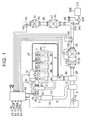
- FIG. 1 shows a diesel engine (hereinafter, simply referred to as an "engine") to which the exhaust gas control apparatus according to this embodiment is applied and a peripheral configuration thereof.
- engine a diesel engine
- a plurality of cylinders #1 to #4 are disposed in an engine 1.
- a plurality of fuel injection valves 4a to 4d are disposed in a cylinder head 2 to correspond to the respective cylinders #1 to #4. These fuel injection valves 4a to 4d inject a fuel into combustion chambers of the respective cylinders #1 to #4.
- An intake port for introducing fresh air into the cylinders and exhaust ports 6a to 6d for discharging combustion gas out of the cylinders are disposed in the cylinder head 2 to correspond to the respective cylinders #1 to #4.
- the fuel injection valves 4a to 4d are connected to a common rail 9 that accumulates a high-pressure fuel.
- the common rail 9 is connected to a supply pump 10.
- the supply pump 10 suctions the fuel in a fuel tank and supplies the high-pressure fuel to the common rail 9.
- the fuel injection valves 4a to 4d are open, the high-pressure fuel supplied to the common rail 9 is injected into the cylinders from the respective fuel injection valves 4a to 4d.
- An intake manifold 7 is connected to the intake port.
- the intake manifold 7 is connected to an intake passage 3.
- An intake throttle valve 16 for suctioned air amount adjustment is disposed in the intake passage 3.
- An exhaust manifold 8 is connected to the exhaust ports 6a to 6d.
- the exhaust manifold 8 is connected to an exhaust passage 26.
- a turbocharger 11, which supercharges suctioned air introduced into the cylinders by using an exhaust gas pressure, is disposed in the middle of the exhaust passage 26.
- an intercooler 18 is disposed between an intake side compressor of the turbocharger 11 and the intake throttle valve 16. The intercooler 18 cools the suctioned air with a temperature raised by the supercharging by the turbocharger 11.
- a first purification member 30 that purifies exhaust gas is disposed on the downstream side of an exhaust side turbine of the turbocharger 11 and in the middle of the exhaust passage 26.
- an oxidation catalyst 31 and a filter 32 are arranged in series with respect to a direction in which the exhaust gas flows.
- a catalyst that performs an oxidation treatment on HC in the exhaust gas is supported on the oxidation catalyst 31.
- the filter 32 is a member that collects particulate matter (PM) in the exhaust gas and is configured to use porous ceramic.
- a catalyst that promotes PM oxidation is supported on the filter 32. The PM in the exhaust gas is collected when the exhaust gas passes through a porous wall of the filter 32.
- a fuel adding valve 5 for adding the fuel to the exhaust gas is disposed in the vicinity of a merging portion of the exhaust manifold 8.
- the fuel adding valve 5 is connected to the supply pump 10 via a fuel supply pipe 27.
- a position at which the fuel adding valve 5 is arranged can be appropriately changed insofar as the position is on the upstream side of the first purification member 30 in an exhaust system.
- the fuel may be added to the exhaust gas by a post injection being performed with a fuel injection timing adjusted.
- a regeneration treatment for the filter 32 is initiated.
- the fuel is injected into the exhaust manifold 8 from the fuel adding valve 5.
- the fuel that is injected from the fuel adding valve 5 is oxidized upon reaching the oxidation catalyst 31.
- the temperature of the exhaust gas rises.
- the temperature of the filter 32 rises by the exhaust gas heated at the oxidation catalyst 31 flowing into the filter 32. In this manner, the filter 32 is regenerated by the PM deposited in the filter 32 being subjected to the oxidation treatment.
- a second purification member 40 that purifies the exhaust gas is disposed on the downstream side of the first purification member 30 and in the middle of the exhaust passage 26.
- a selective reduction-type NOx catalyst (hereinafter, referred to as a SCR catalyst) 41 that reduces and removes the NOx in the exhaust gas by using ammonia is arranged in the second purification member 40.
- a third purification member 50 that purifies the exhaust gas is disposed on the downstream side of the second purification member 40 and in the middle of the exhaust passage 26.
- An ammonia oxidation catalyst 51 that removes the ammonia in the exhaust gas is arranged in the third purification member 50.
- a urea water supply mechanism 200 as an adding mechanism that adds urea water to the exhaust gas is disposed in the engine 1.
- the urea water supply mechanism 200 is configured to be provided with a tank 210 that stores the urea water, a urea adding valve 230 that supplies the urea water into the exhaust passage 26 by injection, a supply passage 240 that connects the urea adding valve 230 and the tank 210 to each other, and a pump 220 that is disposed in the middle of the supply passage 240.
- the urea adding valve 230 is disposed between the first purification member 30 and the second purification member 40 on the exhaust passage 26. When the urea adding valve 230 is open, the urea water is supplied by injection into the exhaust passage 26 via the supply passage 240.
- the pump 220 is an electric pump. During a positive rotation of the pump 220, the urea water is fed from the tank 210 toward the urea adding valve 230. During a reverse rotation of the pump 220, the urea water is fed from the urea adding valve 230 to the tank 210. In other words, during the reverse rotation of the pump 220, the urea water is recovered from the urea adding valve 230 and the supply passage 240 and is returned to the tank 210.
- a dispersion plate 60 is disposed between the urea adding valve 230 and the SCR catalyst 41 in the exhaust passage 26.
- the dispersion plate 60 promotes the atomization of the urea water by dispersing the urea water injected from the urea adding valve 230.
- the urea water injected from the urea adding valve 230 becomes ammonia after being hydrolyzed by heat of the exhaust gas. This ammonia is adsorbed onto the SCR catalyst 41 upon reaching the SCR catalyst 41. Then, the NOx is reduced and removed by the use of the ammonia adsorbed on the SCR catalyst 41.
- a maximum ammonia adsorption amount of the SCR catalyst 41 decreases as a SCR bed temperature ST, which is the temperature of the SCR catalyst 41, increases and the SCR catalyst 41 becomes incapable of adsorbing the ammonia once the SCR bed temperature ST exceeds an adsorption limit temperature UT.
- a desorption initiation temperature DT is a temperature that is lower than the adsorption limit temperature UT.
- the amount of the ammonia that is desorbed from the SCR catalyst 41 increases as the SCR bed temperature ST increases. Accordingly, as the SCR bed temperature ST increases with a rise in the exhaust gas temperature, the maximum ammonia adsorption amount decreases and the ammonia desorption amount increases.
- the engine 1 is provided with an exhaust gas recirculation device (hereinafter, referred to as an EGR device), too.
- An EGR passage 13, an EGR valve 15, an EGR cooler 14, and the like constitute the EGR device.
- the EGR passage 13 allows the intake manifold 7 and the exhaust manifold 8 to communicate with each other.
- the EGR valve 15 is disposed on the EGR passage 13.
- the EGR cooler 14 is disposed in the middle of the EGR passage 13.
- An EGR amount which is the amount of the exhaust gas that is returned to the intake passage from the exhaust passage 26, is adjusted by an adjustment of the opening degree of the EGR valve 15 in accordance with engine operation states.
- the temperature of the exhaust gas that flows through the EGR passage 13 is lowered by the EGR cooler 14.
- an air flow meter 19 detects a suctioned air amount GA.
- a throttle valve opening degree sensor 20 detects an opening degree of the intake throttle valve 16.
- a crank angle sensor 21 detects an engine rotation speed NE.
- An accelerator sensor 22 detects an accelerator pedal depression amount, that is, an accelerator operation amount ACCP.
- An outside air temperature sensor 23 detects an outside air temperature THout.
- a vehicle speed sensor 24 detects a vehicle speed SPD of a vehicle in which the engine 1 is mounted.
- a first exhaust gas temperature sensor 100 that is disposed on the upstream side of the oxidation catalyst 31 detects a first exhaust gas temperature TH1, which is the temperature of the exhaust gas flowing into the oxidation catalyst 31.
- a differential pressure sensor 110 detects a pressure difference ⁇ P between the exhaust gas pressure on the upstream side of the filter 32 and the exhaust gas pressure on the downstream side of the filter 32.
- a second exhaust gas temperature sensor 120 and a first NOx sensor 130 are disposed on the upstream side of the urea adding valve 230 and between the first purification member 30 and the second purification member 40.
- the second exhaust gas temperature sensor 120 detects a second exhaust gas temperature TH2, which is the temperature of the exhaust gas flowing into the SCR catalyst 41.
- This second exhaust gas temperature TH2 is more suitable than the first exhaust gas temperature TH1 as a temperature correlated to the temperature of the SCR catalyst 41.
- the first NOx sensor 130 detects a first NOx concentration N1, which is a NOx concentration of the exhaust gas that has not yet flown into the SCR catalyst 41.
- a second NOx sensor 140 is disposed on the downstream side of the third purification member 50.
- the second NOx sensor 140 detects a second NOx concentration N2, which is the NOx concentration of the exhaust gas purified by the SCR catalyst 41.
- This control device 80 for instance, consists of an electronic control unit and is configured to have a microcomputer as a main component.
- the microcomputer is provided with a central processing unit (CPU), a read-only memory (ROM) in which various programs, maps, and the like are stored in advance, a random access memory (RAM) that temporarily stores a calculation result of the CPU and the like, a timer counter, an input interface, an output interface, and the like.
- CPU central processing unit
- ROM read-only memory
- RAM random access memory
- the control device 80 performs various types of controls for the engine 1 such as fuel injection quantity and timing controls for the fuel injection valves 4a to 4d and the fuel adding valve 5, a discharge pressure control for the supply pump 10, a driving amount control for an actuator 17 that opens and closes the intake throttle valve 16, and an opening degree control for the EGR valve 15.
- the control device 80 controls urea water addition by the urea adding valve 230 as an example of the exhaust gas purification control.
- a urea addition amount QE that is required for a reduction treatment of the NOx discharged from the engine 1 is calculated based on the engine operation state and the like.
- the opening state of the urea adding valve 230 is controlled such that the urea water equivalent in amount to the calculated urea addition amount QE is injected from the urea adding valve 230.
- the control device 80 also executes an ammonia adsorption amount control, which controls the ammonia adsorption amount of the SCR catalyst 41, as an example of this addition control.
- a target ammonia adsorption amount NHp that is required for the NOx reduction treatment to be performed in the SCR catalyst 41 is set.
- a constant fixed value NH1 is set as the target adsorption amount NHp in a case where the SCR bed temperature ST is equal to or lower than a predetermined temperature ST1.
- the target adsorption amount NHp is set to an amount that is smaller than the fixed value NH1. More specifically, the target adsorption amount NHp is variably set to decrease as the SCR bed temperature ST increases.
- the ammonia adsorption amount is controlled, so that the actual ammonia adsorption amount of the SCR catalyst 41 (hereinafter, referred to as an actual adsorption amount) corresponds to the target adsorption amount NHp, by the urea addition amount QE being corrected based on the target adsorption amount NHp.
- the control device 80 executes the following integration or incrementing processing and initialization processing in order to suppress the increase in the error.
- the control device 80 first calculates a temperature integrated or incremented value HS as an example of a parameter for determining whether or not the high-temperature state of the SCR catalyst 41 has continued for a long period of time.
- the temperature integrated value HS is an integrated value of the temperature of the SCR catalyst 41 at a time when the temperature of the SCR catalyst 41 is equal to or higher than a threshold determined in advance, more specifically, when the temperature of the SCR catalyst 41 is equal to or higher than the desorption initiation temperature DT at which the ammonia is desorbed from the SCR catalyst 41.
- FIG. 4 A procedure of the integration or incrementing processing for the calculation of the temperature integrated value HS is illustrated in FIG. 4 .
- This processing is repeatedly executed at a predetermined cycle.
- the control device 80 reads the second exhaust gas temperature TH2 that is a detected value of the temperature of the exhaust gas flowing into the SCR catalyst 41 and an exhaust gas flow rate EA that is the flow rate of the exhaust gas flowing into the SCR catalyst 41 (S100).
- the exhaust gas flow rate EA can be obtained from the suctioned air amount GA, an engine load, the engine rotation speed NE, or the like.
- the control device 80 sets a correction factor KT based on the exhaust gas flow rate EA (S110).
- This correction factor KT is a value for correcting the second exhaust gas temperature TH2, and a value that exceeds "0" and is equal to or less than "1" is variably set to the correction factor KT based on the exhaust gas flow rate EA. More specifically, the correction factor KT is set to decrease as the exhaust gas flow rate EA decreases.
- the control device 80 calculates a temperature corresponding to the SCR bed temperature ST (S120), that is, a catalyst temperature THEH which is the temperature of the SCR catalyst 41, by correcting the second exhaust gas temperature TH2 with the correction factor KT based on the following Equation (1).
- Catalyst temperature THEH Second exhaust gas temperature TH 2 ⁇ Correction factor KT
- the correction factor KT is a value that exceeds "0" and is equal to or less than "1" and is set to decrease as the exhaust gas flow rate EA decreases. Accordingly, in the processing of Step S120, the second exhaust gas temperature TH2 that is a value detected by the second exhaust gas temperature sensor 120 is corrected to decrease as the exhaust gas flow rate EA decreases, and the second exhaust gas temperature TH2 subsequent to that correction is set to the catalyst temperature THEH.
- control device 80 determines whether or not the catalyst temperature THEH calculated in Step S120 is equal to or higher than the desorption initiation temperature DT described above (S130). When the catalyst temperature THEH is smaller than the desorption initiation temperature DT (S130: NO), the control device 80 terminates this processing.
- Step S140 the temperature integrated value HS at a time of the current execution of this processing is calculated by the addition of the catalyst temperature THEH calculated in Step S120 and of the temperature integrated value HS calculated at a time of the previous execution of this processing.
- the temperature incremented value HS is incremented by the temperature THEH of the catalyst 41 calculated in Step S120.
- the temperature integrated value HS increases by catalyst temperature THEH at every integration processing execution cycle in a case where the catalyst temperature THEH is equal to or higher than the desorption initiation temperature DT described above.
- the temperature integrated value HS is reset to "0" at a point in time when the initialization processing (described later) is terminated and at a point in time when the regeneration treatment for the filter 32 is terminated, and then the integration is initiated again.
- the temperature of the SCR catalyst 41 is raised by heat transfer from the exhaust gas.
- the amount of the heat that is transferred from the exhaust gas to the SCR catalyst 41 decreases as the flow rate of the exhaust gas flowing into the SCR catalyst 41 decreases. Accordingly, when the temperature of the SCR catalyst 41 is calculated with the effect of the exhaust gas flow rate taken into account, the temperature of the SCR catalyst 41 can be accurately calculated. As a result, the temperature integrated value HS can be accurately calculated.
- Step S100 each of the processing of Step S100, Step S110, and Step S120 is executed.
- the detected value of the temperature of the exhaust gas flowing into the SCR catalyst 41 is corrected to decrease as the flow rate of the exhaust gas flowing into the SCR catalyst 41 decreases, and the temperature resulting from this correction is used as the catalyst temperature THEH.
- Step S140 the temperature integrated value HS is calculated by the integration of the catalyst temperature THEH. Accordingly, the catalyst temperature THEH decreases as the exhaust gas flow rate EA decreases. As a result, the temperature integrated value HS calculated in Step S140 decreases as the exhaust gas flow rate EA decreases.
- the effect of the exhaust gas flow rate EA regarding the amount of the heat transferred from the exhaust gas to the SCR catalyst 41 is taken into account, and thus the temperature integrated value HS is accurately calculated.
- the control device 80 executes the initialization processing for decreasing the amount of the ammonia adsorbed on the SCR catalyst 41 to "0".
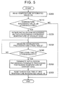
- FIG. 5 shows a series of processing procedures for the execution of the initialization processing. This processing is also repeatedly executed at a predetermined cycle.
- the control device 80 first reads the current temperature integrated value HS (S200). Then, the control device 80 determines whether or not the temperature integrated value HS is equal to or greater than the threshold HS 1 (S210). When the high-temperature state of the SCR catalyst 41 continues for a long period of time, the temperature integrated value HS increases. Accordingly, it is conceivable that the amount of the ammonia desorbed from the SCR catalyst 41 is likely to increase and a cumulative value of the error of the actual adsorption amount NHR with respect to the target adsorption amount NHp increases as the temperature integrated value HS increases.
- a value of the temperature integrated value HS that corresponds to an unallowable increase of the cumulative value of the error of the actual adsorption amount NHR with respect to the target adsorption amount NHp is set to the threshold HS 1 in advance through an experiment or the like.
- the control device 80 terminates this processing.
- the control device 80 initiates the initialization processing (S220) for decreasing the amount of the ammonia adsorbed on the SCR catalyst 41 to "0".
- a temperature-raising processing for raising the temperature of the exhaust gas flowing into the SCR catalyst 41 is executed as this initialization processing.
- This temperature-raising processing can be appropriately executed.
- the temperature of the exhaust gas can be raised by fuel addition from the fuel adding valve 5 being executed or the post injection being executed.
- the temperature-raising processing is executed, the temperature of the exhaust gas is raised to the temperature at which the ammonia is desorbed from the SCR catalyst 41. More specifically, the temperature of the exhaust gas is raised to at least a temperature at which the amount of the ammonia desorbed from the SCR catalyst 41 exceeds the amount of the ammonia adsorbed onto the SCR catalyst 41.
- the temperature of the exhaust gas is raised to the adsorption limit temperature UT at which the SCR catalyst 41 becomes incapable of the ammonia adsorption.
- the regeneration treatment for the filter 32 may be forcibly initiated as the initialization processing as well.
- This execution time ET represents the length of time elapsed since the initiation of the initialization processing.
- control device 80 determines whether or not the execution time ET is equal to or longer than a threshold ET1 (S240).
- the execution time ET that is required for a complete desorption of the ammonia adsorbed on the SCR catalyst 41 is set in advance to this threshold ET1.
- the control device 80 When the execution time ET becomes smaller than the threshold ET1 (S240: NO), the control device 80 repeatedly performs the processing of Step S230 and the processing of Step S240 until the execution time ET becomes equal to or longer than the threshold ET1.
- the control device 80 terminates the initialization processing. In other words, the control device 80 terminates the processing for raising the temperature of the exhaust gas (S250) and resets the execution time ET and the temperature integrated value HS to "0" (S260). Then, the control device 80 terminates this processing.
- the SCR bed temperature ST gradually increases by the initialization processing being initiated once the temperature integrated value HS becomes equal to or greater than the threshold HS1 at time t1. Because of this rise in the SCR bed temperature ST, the desorption of the ammonia from the SCR catalyst 41 is prompted, and thus the actual adsorption amount NHR ultimately becomes "0" after being gradually decreased as illustrated by a solid line L1.
- the target adsorption amount NHp gradually decreases with the rise in the SCR bed temperature ST.
- the SCR bed temperature ST reaches the adsorption limit temperature UT at time t2
- the ammonia adsorption becomes impossible, and thus the target adsorption amount NHp is set to "0".
- the urea addition amount also gradually decreases.
- the target adsorption amount NHp is set to "0" at time t2
- the urea addition amount for the ammonia adsorption is set to "0".
- the initialization processing is terminated and the SCR bed temperature ST declines.
- the ammonia adsorption amount control based on urea addition is initiated. In other words, setting of the target adsorption amount NHp based on the SCR bed temperature ST is performed and the urea addition for the ammonia adsorption is initiated, which causes the actual adsorption amount NHR to begin to increase again.
- the initialization processing described above is executed prior to the initiation of the ammonia adsorption amount control at time t3, and thus the actual adsorption amount NHR is temporarily reset to "0". Accordingly, a cumulative error ⁇ G of the actual adsorption amount NHR with respect to the target adsorption amount NHp preceding the initiation of the execution of the initialization processing is eliminated. Accordingly, the period subsequent to time t3 is a state where the deviation of the actual adsorption amount NHR with respect to the target adsorption amount NHp is reduced, in which the actual adsorption amount NHR of the SCR catalyst 41 is maintained at an appropriate amount in accordance with the target adsorption amount NHp.
- the actual adsorption amount NHR is "0", and thus it is desirable that the actual adsorption amount NHR is increased rapidly. Accordingly, immediately after the initiation of the ammonia adsorption amount control at time t3 in FIG. 6 , the actual adsorption amount NHR may be rapidly increased not by the target adsorption amount NHp being set based on the SCR bed temperature ST but by a relatively high value being set as the target adsorption amount NHp.
- the temperature integrated value HS is calculated, which is the integrated value of the temperature of the SCR catalyst 41 at the time when the temperature of the SCR catalyst 41 is equal to or higher than the threshold determined in advance, more specifically, when the temperature of the SCR catalyst 41 is equal to or higher than the temperature at which the ammonia is desorbed. Then, on the condition that the temperature integrated value HS has become equal to or greater than the threshold HS1, the initialization processing for decreasing the amount of the ammonia adsorbed on the SCR catalyst 41 to "0" is executed.
- the initialization processing is reliably executed based on the temperature integrated value HS. Accordingly, the risk of an increase in the error of the actual adsorption amount NHR with respect to the target adsorption amount NHp that is attributable to the continuation of a state where the initialization processing is not executed can be reduced.
- the constant fixed value NH1 is set as the target adsorption amount NHp in a case where the SCR bed temperature ST is equal to or lower than the temperature ST1.
- the manner in which the target adsorption amount NHp is set can be appropriately changed.
- the target adsorption amount NHp may be variably set in accordance with the SCR bed temperature ST even in a case where the SCR bed temperature ST is equal to or lower than the temperature ST1.
- the target adsorption amount NHp may variably be set based on the amount of the NOx flowing into the SCR catalyst 41 per unit time.
- the second exhaust gas temperature TH2 is corrected based on the exhaust gas flow rate EA in the integration processing for the calculation of the temperature integrated value HS.
- the temperature integrated value HS may also be calculated by the integration of the catalyst temperature THEH without this correction and the second exhaust gas temperature TH2 may be used as the catalyst temperature THEH as it is.
- the second exhaust gas temperature TH2 which is the temperature of the exhaust gas flowing into the SCR catalyst 41, is actually detected by the second exhaust gas temperature sensor 120.
- another method may also be adopted for the detection of the second exhaust gas temperature TH2, examples of which include estimation of the temperature of the exhaust gas flowing into the SCR catalyst 41 based on the engine operation states such as the engine load and the engine rotation speed and use of the estimated value as the second exhaust gas temperature TH2.
- the temperature-raising processing for raising the temperature of the exhaust gas flowing into the SCR catalyst 41 is executed as the initialization processing.
- a processing for stopping the urea water addition from the urea water supply mechanism 200 may be executed as the initialization processing as well.
- the temperature-raising processing for raising the temperature of the exhaust gas flowing into the SCR catalyst 41 and the processing for stopping the urea water addition from the urea water supply mechanism 200 may be used in combination with each other as the initialization processing, too.
- the initialization processing is performed until the actual ammonia adsorption amount NHR becomes "0".
- the actual adsorption amount NHR does not necessarily have to be decreased to "0” and the actual adsorption amount NHR may slightly exceed "0" at the completion of the initialization processing.
- the initialization processing described above may be executed so that the amount of the ammonia adsorbed on the SCR catalyst 41 is subjected to any decrease on the condition that the temperature integrated value HS has become equal to or greater than the threshold HS1.
- the initialization processing is reliably executed based on the temperature integrated value HS. Accordingly, the risk of an increase in the error of the actual adsorption amount NHR with respect to the target adsorption amount NHp that is attributable to the continuation of the state where the initialization processing is not executed can be reduced.
Landscapes
- Engineering & Computer Science (AREA)
- Chemical & Material Sciences (AREA)
- Combustion & Propulsion (AREA)
- Mechanical Engineering (AREA)
- General Engineering & Computer Science (AREA)
- Chemical Kinetics & Catalysis (AREA)
- Health & Medical Sciences (AREA)
- Toxicology (AREA)
- Exhaust Gas After Treatment (AREA)
- Exhaust Gas Treatment By Means Of Catalyst (AREA)
- Combined Controls Of Internal Combustion Engines (AREA)
Abstract
Description
- The disclosure relates to an exhaust gas control system and an exhaust gas control apparatus for an internal combustion engine.
- Japanese Patent Application Publication No.
2014-88800 JP 2014-88800 A - When the amount of the ammonia adsorbed on the catalyst is insufficient, an appropriate NOx removal cannot be performed. When the ammonia adsorption amount is excessive, an ammonia slip is likely to occur. Accordingly, it is desirable to execute an ammonia adsorption amount control, which is designed to set a target adsorption amount for the ammonia adsorbed onto the catalyst and to control a urea water addition amount based on the target adsorption amount.
- Inhibiting an error between the target adsorption amount and the actual ammonia adsorption amount is important in executing the ammonia adsorption amount control. When a high-temperature state of the catalyst continues for a long period of time, however, the amount of the ammonia that is desorbed from the catalyst increases, and thus the actual ammonia adsorption amount deviates from the target adsorption amount, which causes the error to be accumulated.
- In the apparatus that is disclosed in
JP 2014-88800 A - In the apparatus that is disclosed in
JP 2014-88800 A - The disclosure provides an exhaust gas control system and an exhaust gas control method for an internal combustion engine configured to reduce the risk of an increase in an error of an actual ammonia adsorption amount with respect to a target adsorption amount that is attributable to the continuation of a state where an initialization processing is not executed.
- An example aspect of the disclosure provides an exhaust gas control system for an internal combustion engine. The internal combustion engine includes an exhaust gas control apparatus. The exhaust gas control apparatus includes an adding mechanism and a catalyst. The adding mechanism is configured to add urea water to exhaust gas. The catalyst is configured to adsorb ammonia resulting from the urea water and remove NOx by using the adsorbed ammonia. The exhaust gas control system includes an electronic control unit configured to: set a target adsorption amount for the ammonia adsorbed onto the catalyst; control a urea water addition amount based on the target adsorption amount; acquire a temperature of the catalyst; execute a first processing for acquiring a parameter correlated to the time period during which the temperature of the catalyst is equal to or higher than a threshold determined in advance; and execute an initialization processing for decreasing the amount of the ammonia adsorbed on the catalyst on a condition that said parameter acquired in the first processing is equal to or higher than a predetermined value. For instance, the parameter acquired in the first processing is an incremented value of the temperature of the catalyst, said incremented value being incremented by the temperature of the catalyst at a predetermined cycle when the temperature of the catalyst is equal to or higher than said threshold, the initialization processing being executed when the incremented value of the temperature of the catalyst has become equal to or higher than a predetermined value.
- As described above, when a high-temperature state of the catalyst continues for a long period of time, an error between the target adsorption amount and the actual ammonia adsorption amount is accumulated and increased. In this regard, according to the configuration described above, the temperature of the catalyst equal to or higher than the threshold determined in advance is integrated as a parameter for determining whether or not the high-temperature state of the catalyst has continued for a long period of time. Then, the initialization processing is executed in a case where it can be determined by the incremented value of the temperature of the catalyst being equal to or higher than the predetermined value that the cumulative error between the target adsorption amount and the actual ammonia adsorption amount has been increased, and thus the initialization processing is reliably executed based on the integrated value of the temperature of the catalyst. Accordingly, an increase in the error of the actual ammonia adsorption amount with respect to the target adsorption amount that is attributable to the continuation of a state where the initialization processing is not executed can be reduced.
- In the exhaust gas control system, the electronic control unit may be configured to acquire a temperature of the exhaust gas flowing into the catalyst, the electronic control unit may be configured to acquire a flow rate of the exhaust gas flowing into the catalyst, and the electronic control unit may be configured to decrease the acquired exhaust gas temperature as the acquired exhaust gas flow rate decreases and use the decreased temperature as the temperature of the catalyst.
- The temperature of the catalyst is raised by heat transfer from the exhaust gas. The amount of the heat that is transferred from the exhaust gas to the catalyst decreases as the flow rate of the exhaust gas flowing into the catalyst decreases. Accordingly, when the temperature of the catalyst is calculated with the effect of the exhaust gas flow rate taken into account, the temperature of the catalyst can be accurately calculated. As a result, the integrated value of the temperature of the catalyst can also be accurately calculated.
- According to the configuration described above, the temperature of the exhaust gas flowing into the catalyst and the flow rate of the exhaust gas flowing into the catalyst are acquired. Then, the acquired exhaust gas temperature is decreased as the acquired exhaust gas flow rate decreases and the corrected temperature is used as the temperature of the catalyst. Accordingly, the temperature of the catalyst that is acquired by the electronic control unit decreases as the flow rate of the exhaust gas decreases. As a result, the integrated value of the catalyst temperature calculated in the initialization processing decreases as the exhaust gas flow rate decreases. During the calculation of the integrated value of the temperature of the catalyst as described above, the effect of the exhaust gas flow rate regarding the amount of the heat transferred from the exhaust gas to the catalyst is taken into account, and thus the integrated value of the temperature of the catalyst can be accurately calculated.
- In the exhaust gas control system, the electronic control unit may be configured to execute, as the initialization processing, a temperature-raising processing for raising the temperature of the exhaust gas flowing into the catalyst to a temperature at which the ammonia is desorbed from the catalyst.
- According to the configuration described above, the ammonia desorption from the catalyst is prompted since the catalyst temperature is raised by the temperature-raising processing. Accordingly, the amount of the ammonia adsorbed on the catalyst can be decreased.
- In the exhaust gas control system, the electronic control unit may be configured to execute, as the initialization processing, a processing for stopping the urea water addition from the adding mechanism. According to the configuration described above, the urea water addition is stopped, and thus a reduction treatment of the NOx flowing into the catalyst is performed by the ammonia adsorbed on the catalyst before the urea water addition is stopped. Accordingly, the ammonia adsorbed on the catalyst is consumed by a NOx reduction reaction with the NOx, and the ammonia adsorption amount of the catalyst gradually decreases. Accordingly, the amount of the ammonia adsorbed on the catalyst can be decreased in the end.
- In the exhaust gas control system, the electronic control unit may be configured to measure an execution time of the initialization processing and execute the initialization processing until the measured execution time reaches a threshold determined in advance.
- According to the configuration described above, the initialization processing can be terminated in a stage in which the amount of the ammonia adsorbed on the catalyst becomes "0" by the execution time threshold being appropriately set.
- Another example aspect of the disclosure provides an exhaust gas control method for an internal combustion engine. The internal combustion engine includes an exhaust gas control apparatus. The exhaust gas control apparatus includes an adding mechanism and a catalyst. The adding mechanism is configured to add urea water to exhaust gas, and the catalyst is configured to adsorb ammonia resulting from the urea water and remove NOx by using the adsorbed ammonia. The exhaust gas control method includes: setting a target adsorption amount for the ammonia adsorbed onto the catalyst and controlling a urea water addition amount based on the target adsorption amount; acquiring a temperature of the catalyst; executing a first processing for acquiring a parameter correlated to the time period during which the temperature of the catalyst is equal to or higher than a threshold determined in advance; and executing an initialization processing for decreasing the amount of the ammonia adsorbed on the catalyst on a condition that said parameter acquired in the first processing is equal to or higher than a predetermined value. For instance, said parameter is an incremented value of the temperature of the catalyst, said incremented value being incremented by the temperature of the catalyst at a predetermined cycle when the temperature of the catalyst is equal to or higher than said threshold, the initialization processing being executed when the incremented value of the temperature of the catalyst has become equal to or higher than a predetermined value.
- Features, advantages, and technical and industrial significance of exemplary embodiments of the disclosure will be described below with reference to the accompanying drawings, in which like numerals denote like elements, and wherein:
-
FIG. 1 is a schematic diagram illustrating an internal combustion engine to which an embodiment of an exhaust gas control apparatus for an internal combustion engine is applied and a peripheral configuration thereof; -
FIG. 2 is a graph illustrating a relationship of a maximum ammonia adsorption amount and of an ammonia desorption amount to a catalyst temperature; -
FIG. 3 is a graph illustrating a relationship between the catalyst temperature and a target adsorption amount; -
FIG. 4 is a flowchart illustrating a procedure of an integration processing according to the embodiment; -
FIG. 5 is a flowchart illustrating a series of processing procedures at a time when an initialization processing according to the embodiment is executed; -
FIG. 6 is a timing chart illustrating an effect of the initialization processing according to the embodiment; and -
FIG. 7 is a timing chart illustrating an effect of an initialization processing according to a modification example of the embodiment. - Hereinafter, a specific embodiment of an exhaust gas control apparatus for an internal combustion engine will be described with reference to
FIGS. 1 to 6 .FIG. 1 shows a diesel engine (hereinafter, simply referred to as an "engine") to which the exhaust gas control apparatus according to this embodiment is applied and a peripheral configuration thereof. - A plurality of
cylinders # 1 to #4 are disposed in anengine 1. A plurality offuel injection valves 4a to 4d are disposed in acylinder head 2 to correspond to therespective cylinders # 1 to #4. Thesefuel injection valves 4a to 4d inject a fuel into combustion chambers of therespective cylinders # 1 to #4. An intake port for introducing fresh air into the cylinders andexhaust ports 6a to 6d for discharging combustion gas out of the cylinders are disposed in thecylinder head 2 to correspond to therespective cylinders # 1 to #4. - The
fuel injection valves 4a to 4d are connected to acommon rail 9 that accumulates a high-pressure fuel. Thecommon rail 9 is connected to asupply pump 10. Thesupply pump 10 suctions the fuel in a fuel tank and supplies the high-pressure fuel to thecommon rail 9. When thefuel injection valves 4a to 4d are open, the high-pressure fuel supplied to thecommon rail 9 is injected into the cylinders from the respectivefuel injection valves 4a to 4d. - An intake manifold 7 is connected to the intake port. The intake manifold 7 is connected to an
intake passage 3. Anintake throttle valve 16 for suctioned air amount adjustment is disposed in theintake passage 3. - An
exhaust manifold 8 is connected to theexhaust ports 6a to 6d. Theexhaust manifold 8 is connected to anexhaust passage 26. Aturbocharger 11, which supercharges suctioned air introduced into the cylinders by using an exhaust gas pressure, is disposed in the middle of theexhaust passage 26. On theintake passage 3, anintercooler 18 is disposed between an intake side compressor of theturbocharger 11 and theintake throttle valve 16. Theintercooler 18 cools the suctioned air with a temperature raised by the supercharging by theturbocharger 11. - A
first purification member 30 that purifies exhaust gas is disposed on the downstream side of an exhaust side turbine of theturbocharger 11 and in the middle of theexhaust passage 26. In thefirst purification member 30, anoxidation catalyst 31 and afilter 32 are arranged in series with respect to a direction in which the exhaust gas flows. - A catalyst that performs an oxidation treatment on HC in the exhaust gas is supported on the
oxidation catalyst 31. Thefilter 32 is a member that collects particulate matter (PM) in the exhaust gas and is configured to use porous ceramic. A catalyst that promotes PM oxidation is supported on thefilter 32. The PM in the exhaust gas is collected when the exhaust gas passes through a porous wall of thefilter 32. - A fuel adding valve 5 for adding the fuel to the exhaust gas is disposed in the vicinity of a merging portion of the
exhaust manifold 8. The fuel adding valve 5 is connected to thesupply pump 10 via afuel supply pipe 27. A position at which the fuel adding valve 5 is arranged can be appropriately changed insofar as the position is on the upstream side of thefirst purification member 30 in an exhaust system. The fuel may be added to the exhaust gas by a post injection being performed with a fuel injection timing adjusted. - When the amount of the PM collected by the
filter 32 exceeds a predetermined value, a regeneration treatment for thefilter 32 is initiated. During the regeneration treatment for thefilter 32, the fuel is injected into theexhaust manifold 8 from the fuel adding valve 5. The fuel that is injected from the fuel adding valve 5 is oxidized upon reaching theoxidation catalyst 31. Then, the temperature of the exhaust gas rises. Then, the temperature of thefilter 32 rises by the exhaust gas heated at theoxidation catalyst 31 flowing into thefilter 32. In this manner, thefilter 32 is regenerated by the PM deposited in thefilter 32 being subjected to the oxidation treatment. - A
second purification member 40 that purifies the exhaust gas is disposed on the downstream side of thefirst purification member 30 and in the middle of theexhaust passage 26. A selective reduction-type NOx catalyst (hereinafter, referred to as a SCR catalyst) 41 that reduces and removes the NOx in the exhaust gas by using ammonia is arranged in thesecond purification member 40. - A
third purification member 50 that purifies the exhaust gas is disposed on the downstream side of thesecond purification member 40 and in the middle of theexhaust passage 26. Anammonia oxidation catalyst 51 that removes the ammonia in the exhaust gas is arranged in thethird purification member 50. - A urea
water supply mechanism 200 as an adding mechanism that adds urea water to the exhaust gas is disposed in theengine 1. The ureawater supply mechanism 200 is configured to be provided with atank 210 that stores the urea water, aurea adding valve 230 that supplies the urea water into theexhaust passage 26 by injection, asupply passage 240 that connects theurea adding valve 230 and thetank 210 to each other, and apump 220 that is disposed in the middle of thesupply passage 240. - The
urea adding valve 230 is disposed between thefirst purification member 30 and thesecond purification member 40 on theexhaust passage 26. When theurea adding valve 230 is open, the urea water is supplied by injection into theexhaust passage 26 via thesupply passage 240. - The
pump 220 is an electric pump. During a positive rotation of thepump 220, the urea water is fed from thetank 210 toward theurea adding valve 230. During a reverse rotation of thepump 220, the urea water is fed from theurea adding valve 230 to thetank 210. In other words, during the reverse rotation of thepump 220, the urea water is recovered from theurea adding valve 230 and thesupply passage 240 and is returned to thetank 210. - A
dispersion plate 60 is disposed between theurea adding valve 230 and theSCR catalyst 41 in theexhaust passage 26. Thedispersion plate 60 promotes the atomization of the urea water by dispersing the urea water injected from theurea adding valve 230. - The urea water injected from the
urea adding valve 230 becomes ammonia after being hydrolyzed by heat of the exhaust gas. This ammonia is adsorbed onto theSCR catalyst 41 upon reaching theSCR catalyst 41. Then, the NOx is reduced and removed by the use of the ammonia adsorbed on theSCR catalyst 41. - As illustrated in
FIG. 2 , a maximum ammonia adsorption amount of theSCR catalyst 41 decreases as a SCR bed temperature ST, which is the temperature of theSCR catalyst 41, increases and theSCR catalyst 41 becomes incapable of adsorbing the ammonia once the SCR bed temperature ST exceeds an adsorption limit temperature UT. Once the SCR bed temperature ST exceeds a desorption initiation temperature DT, the ammonia begins to be desorbed from theSCR catalyst 41. The desorption initiation temperature DT is a temperature that is lower than the adsorption limit temperature UT. The amount of the ammonia that is desorbed from theSCR catalyst 41 increases as the SCR bed temperature ST increases. Accordingly, as the SCR bed temperature ST increases with a rise in the exhaust gas temperature, the maximum ammonia adsorption amount decreases and the ammonia desorption amount increases. - The
engine 1 is provided with an exhaust gas recirculation device (hereinafter, referred to as an EGR device), too. AnEGR passage 13, anEGR valve 15, anEGR cooler 14, and the like constitute the EGR device. TheEGR passage 13 allows the intake manifold 7 and theexhaust manifold 8 to communicate with each other. TheEGR valve 15 is disposed on theEGR passage 13. TheEGR cooler 14 is disposed in the middle of theEGR passage 13. An EGR amount, which is the amount of the exhaust gas that is returned to the intake passage from theexhaust passage 26, is adjusted by an adjustment of the opening degree of theEGR valve 15 in accordance with engine operation states. The temperature of the exhaust gas that flows through theEGR passage 13 is lowered by theEGR cooler 14. - Various sensors for engine operation state detection are attached to the
engine 1. For example, anair flow meter 19 detects a suctioned air amount GA. A throttle valveopening degree sensor 20 detects an opening degree of theintake throttle valve 16. A crank angle sensor 21 detects an engine rotation speed NE. An accelerator sensor 22 detects an accelerator pedal depression amount, that is, an accelerator operation amount ACCP. An outside air temperature sensor 23 detects an outside air temperature THout. A vehicle speed sensor 24 detects a vehicle speed SPD of a vehicle in which theengine 1 is mounted. - A first exhaust
gas temperature sensor 100 that is disposed on the upstream side of theoxidation catalyst 31 detects a first exhaust gas temperature TH1, which is the temperature of the exhaust gas flowing into theoxidation catalyst 31. Adifferential pressure sensor 110 detects a pressure difference ΔP between the exhaust gas pressure on the upstream side of thefilter 32 and the exhaust gas pressure on the downstream side of thefilter 32. - On the
exhaust passage 26, a second exhaustgas temperature sensor 120 and afirst NOx sensor 130 are disposed on the upstream side of theurea adding valve 230 and between thefirst purification member 30 and thesecond purification member 40. The second exhaustgas temperature sensor 120 detects a second exhaust gas temperature TH2, which is the temperature of the exhaust gas flowing into theSCR catalyst 41. This second exhaust gas temperature TH2 is more suitable than the first exhaust gas temperature TH1 as a temperature correlated to the temperature of theSCR catalyst 41. Thefirst NOx sensor 130 detects a first NOx concentration N1, which is a NOx concentration of the exhaust gas that has not yet flown into theSCR catalyst 41. - On the
exhaust passage 26, asecond NOx sensor 140 is disposed on the downstream side of thethird purification member 50. Thesecond NOx sensor 140 detects a second NOx concentration N2, which is the NOx concentration of the exhaust gas purified by theSCR catalyst 41. - Outputs from these various sensors and the like are input to a
control device 80. Thiscontrol device 80, for instance, consists of an electronic control unit and is configured to have a microcomputer as a main component. The microcomputer is provided with a central processing unit (CPU), a read-only memory (ROM) in which various programs, maps, and the like are stored in advance, a random access memory (RAM) that temporarily stores a calculation result of the CPU and the like, a timer counter, an input interface, an output interface, and the like. - The
control device 80 performs various types of controls for theengine 1 such as fuel injection quantity and timing controls for thefuel injection valves 4a to 4d and the fuel adding valve 5, a discharge pressure control for thesupply pump 10, a driving amount control for anactuator 17 that opens and closes theintake throttle valve 16, and an opening degree control for theEGR valve 15. - Various exhaust gas purification controls such as the above-described regeneration treatment for the combustion of the PM collected by the
filter 32 are performed by thecontrol device 80, too. Thecontrol device 80 controls urea water addition by theurea adding valve 230 as an example of the exhaust gas purification control. During this addition control, a urea addition amount QE that is required for a reduction treatment of the NOx discharged from theengine 1 is calculated based on the engine operation state and the like. During an ignition control, the opening state of theurea adding valve 230 is controlled such that the urea water equivalent in amount to the calculated urea addition amount QE is injected from theurea adding valve 230. Thecontrol device 80 also executes an ammonia adsorption amount control, which controls the ammonia adsorption amount of theSCR catalyst 41, as an example of this addition control. - As illustrated in
FIG. 3 , during the ammonia adsorption amount control, a target ammonia adsorption amount NHp that is required for the NOx reduction treatment to be performed in theSCR catalyst 41 is set. In this embodiment, a constant fixed value NH1 is set as the target adsorption amount NHp in a case where the SCR bed temperature ST is equal to or lower than a predetermined temperature ST1. In a region where the SCR bed temperature ST exceeds the temperature ST1, the target adsorption amount NHp is set to an amount that is smaller than the fixed value NH1. More specifically, the target adsorption amount NHp is variably set to decrease as the SCR bed temperature ST increases. Then, the ammonia adsorption amount is controlled, so that the actual ammonia adsorption amount of the SCR catalyst 41 (hereinafter, referred to as an actual adsorption amount) corresponds to the target adsorption amount NHp, by the urea addition amount QE being corrected based on the target adsorption amount NHp. - When a high-temperature state of the
SCR catalyst 41 continues for a long period of time, the amount of the ammonia that is desorbed from theSCR catalyst 41 increases. Accordingly, an actual adsorption amount NHR deviates from the target adsorption amount NHp and an error of the actual adsorption amount NHR with respect to the target adsorption amount NHp is accumulated. - The
control device 80 executes the following integration or incrementing processing and initialization processing in order to suppress the increase in the error. Thecontrol device 80 first calculates a temperature integrated or incremented value HS as an example of a parameter for determining whether or not the high-temperature state of theSCR catalyst 41 has continued for a long period of time. The temperature integrated value HS is an integrated value of the temperature of theSCR catalyst 41 at a time when the temperature of theSCR catalyst 41 is equal to or higher than a threshold determined in advance, more specifically, when the temperature of theSCR catalyst 41 is equal to or higher than the desorption initiation temperature DT at which the ammonia is desorbed from theSCR catalyst 41. - A procedure of the integration or incrementing processing for the calculation of the temperature integrated value HS is illustrated in
FIG. 4 . This processing is repeatedly executed at a predetermined cycle. Once this processing is initiated, thecontrol device 80 reads the second exhaust gas temperature TH2 that is a detected value of the temperature of the exhaust gas flowing into theSCR catalyst 41 and an exhaust gas flow rate EA that is the flow rate of the exhaust gas flowing into the SCR catalyst 41 (S100). The exhaust gas flow rate EA can be obtained from the suctioned air amount GA, an engine load, the engine rotation speed NE, or the like. - Then, the
control device 80 sets a correction factor KT based on the exhaust gas flow rate EA (S110). This correction factor KT is a value for correcting the second exhaust gas temperature TH2, and a value that exceeds "0" and is equal to or less than "1" is variably set to the correction factor KT based on the exhaust gas flow rate EA. More specifically, the correction factor KT is set to decrease as the exhaust gas flow rate EA decreases. - Then, the
control device 80 calculates a temperature corresponding to the SCR bed temperature ST (S120), that is, a catalyst temperature THEH which is the temperature of theSCR catalyst 41, by correcting the second exhaust gas temperature TH2 with the correction factor KT based on the following Equation (1).
- As described above, the correction factor KT is a value that exceeds "0" and is equal to or less than "1" and is set to decrease as the exhaust gas flow rate EA decreases. Accordingly, in the processing of Step S120, the second exhaust gas temperature TH2 that is a value detected by the second exhaust
gas temperature sensor 120 is corrected to decrease as the exhaust gas flow rate EA decreases, and the second exhaust gas temperature TH2 subsequent to that correction is set to the catalyst temperature THEH. - Then, the
control device 80 determines whether or not the catalyst temperature THEH calculated in Step S120 is equal to or higher than the desorption initiation temperature DT described above (S130). When the catalyst temperature THEH is smaller than the desorption initiation temperature DT (S130: NO), thecontrol device 80 terminates this processing. - When the catalyst temperature THEH is equal to or higher than the desorption initiation temperature DT (S130: YES), the
control device 80 terminates this processing after executing a processing for updating the temperature integrated value HS (S140). In Step S140, the temperature integrated value HS at a time of the current execution of this processing is calculated by the addition of the catalyst temperature THEH calculated in Step S120 and of the temperature integrated value HS calculated at a time of the previous execution of this processing. In other words, in step S140, the temperature incremented value HS is incremented by the temperature THEH of thecatalyst 41 calculated in Step S120. It is thus understood that the terms "integration" and "integrated" used in the present description refer to an incrementing calculation of the temperature value HS. - By this integration or incrementing processing being repeatedly executed, the temperature integrated value HS increases by catalyst temperature THEH at every integration processing execution cycle in a case where the catalyst temperature THEH is equal to or higher than the desorption initiation temperature DT described above. The temperature integrated value HS is reset to "0" at a point in time when the initialization processing (described later) is terminated and at a point in time when the regeneration treatment for the
filter 32 is terminated, and then the integration is initiated again. - The following effects are achieved by the execution of the integration or incrementing processing illustrated in
FIG. 4 . The temperature of theSCR catalyst 41 is raised by heat transfer from the exhaust gas. The amount of the heat that is transferred from the exhaust gas to theSCR catalyst 41 decreases as the flow rate of the exhaust gas flowing into theSCR catalyst 41 decreases. Accordingly, when the temperature of theSCR catalyst 41 is calculated with the effect of the exhaust gas flow rate taken into account, the temperature of theSCR catalyst 41 can be accurately calculated. As a result, the temperature integrated value HS can be accurately calculated. - In the integration processing according to this embodiment described above, each of the processing of Step S100, Step S110, and Step S120 is executed. Then, the detected value of the temperature of the exhaust gas flowing into the
SCR catalyst 41 is corrected to decrease as the flow rate of the exhaust gas flowing into theSCR catalyst 41 decreases, and the temperature resulting from this correction is used as the catalyst temperature THEH. In Step S140, the temperature integrated value HS is calculated by the integration of the catalyst temperature THEH. Accordingly, the catalyst temperature THEH decreases as the exhaust gas flow rate EA decreases. As a result, the temperature integrated value HS calculated in Step S140 decreases as the exhaust gas flow rate EA decreases. During the calculation of the temperature integrated value HS described above, the effect of the exhaust gas flow rate EA regarding the amount of the heat transferred from the exhaust gas to theSCR catalyst 41 is taken into account, and thus the temperature integrated value HS is accurately calculated. - On a condition that the temperature integrated value HS calculated as described above has become equal to or greater than a predetermined threshold HS1, the
control device 80 executes the initialization processing for decreasing the amount of the ammonia adsorbed on theSCR catalyst 41 to "0". -
FIG. 5 shows a series of processing procedures for the execution of the initialization processing. This processing is also repeatedly executed at a predetermined cycle. Once this processing is initiated, thecontrol device 80 first reads the current temperature integrated value HS (S200). Then, thecontrol device 80 determines whether or not the temperature integrated value HS is equal to or greater than the threshold HS 1 (S210). When the high-temperature state of theSCR catalyst 41 continues for a long period of time, the temperature integrated value HS increases. Accordingly, it is conceivable that the amount of the ammonia desorbed from theSCR catalyst 41 is likely to increase and a cumulative value of the error of the actual adsorption amount NHR with respect to the target adsorption amount NHp increases as the temperature integrated value HS increases. In this regard, a value of the temperature integrated value HS that corresponds to an unallowable increase of the cumulative value of the error of the actual adsorption amount NHR with respect to the target adsorption amount NHp is set to thethreshold HS 1 in advance through an experiment or the like. - When the temperature integrated value HS becomes smaller than the threshold HS1 (S210: NO), the cumulative value of the error of the actual adsorption amount NHR with respect to the target adsorption amount NHp is insignificant. Accordingly, the
control device 80 terminates this processing. - When the temperature integrated value HS is equal to or greater than the threshold HS1 (S210: YES), the cumulative value of the error of the actual adsorption amount NHR with respect to the target adsorption amount NHp reaches an unallowable extent, and thus the
control device 80 initiates the initialization processing (S220) for decreasing the amount of the ammonia adsorbed on theSCR catalyst 41 to "0". - In this embodiment, a temperature-raising processing for raising the temperature of the exhaust gas flowing into the
SCR catalyst 41 is executed as this initialization processing. This temperature-raising processing can be appropriately executed. For example, the temperature of the exhaust gas can be raised by fuel addition from the fuel adding valve 5 being executed or the post injection being executed. When the temperature-raising processing is executed, the temperature of the exhaust gas is raised to the temperature at which the ammonia is desorbed from theSCR catalyst 41. More specifically, the temperature of the exhaust gas is raised to at least a temperature at which the amount of the ammonia desorbed from theSCR catalyst 41 exceeds the amount of the ammonia adsorbed onto theSCR catalyst 41. For example, in this embodiment, the temperature of the exhaust gas is raised to the adsorption limit temperature UT at which theSCR catalyst 41 becomes incapable of the ammonia adsorption. The regeneration treatment for thefilter 32 may be forcibly initiated as the initialization processing as well. - Once the initialization processing is initiated, the
control device 80 measures an initialization processing execution time ET (S230). This execution time ET represents the length of time elapsed since the initiation of the initialization processing. - Then, the
control device 80 determines whether or not the execution time ET is equal to or longer than a threshold ET1 (S240). The execution time ET that is required for a complete desorption of the ammonia adsorbed on theSCR catalyst 41 is set in advance to this threshold ET1. - When the execution time ET becomes smaller than the threshold ET1 (S240: NO), the
control device 80 repeatedly performs the processing of Step S230 and the processing of Step S240 until the execution time ET becomes equal to or longer than the threshold ET1. - Once the execution time ET becomes equal to or longer than the threshold ET1, the
control device 80 terminates the initialization processing. In other words, thecontrol device 80 terminates the processing for raising the temperature of the exhaust gas (S250) and resets the execution time ET and the temperature integrated value HS to "0" (S260). Then, thecontrol device 80 terminates this processing. - Hereinafter, an effect of the initialization processing will be described with reference to
FIG. 6 . The SCR bed temperature ST gradually increases by the initialization processing being initiated once the temperature integrated value HS becomes equal to or greater than the threshold HS1 at time t1. Because of this rise in the SCR bed temperature ST, the desorption of the ammonia from theSCR catalyst 41 is prompted, and thus the actual adsorption amount NHR ultimately becomes "0" after being gradually decreased as illustrated by a solid line L1. - In addition, as illustrated by a two-dot chain line L2, the target adsorption amount NHp gradually decreases with the rise in the SCR bed temperature ST. Once the SCR bed temperature ST reaches the adsorption limit temperature UT at time t2, the ammonia adsorption becomes impossible, and thus the target adsorption amount NHp is set to "0". Because of this decrease in the target adsorption amount NHp associated with the rise in the SCR bed temperature ST, the urea addition amount also gradually decreases. Once the target adsorption amount NHp is set to "0" at time t2, the urea addition amount for the ammonia adsorption is set to "0".
- Once the execution time ET reaches the threshold ET1 at time t3, the initialization processing is terminated and the SCR bed temperature ST declines. In addition, after time t3, the ammonia adsorption amount control based on urea addition is initiated. In other words, setting of the target adsorption amount NHp based on the SCR bed temperature ST is performed and the urea addition for the ammonia adsorption is initiated, which causes the actual adsorption amount NHR to begin to increase again.
- The initialization processing described above is executed prior to the initiation of the ammonia adsorption amount control at time t3, and thus the actual adsorption amount NHR is temporarily reset to "0". Accordingly, a cumulative error ΔG of the actual adsorption amount NHR with respect to the target adsorption amount NHp preceding the initiation of the execution of the initialization processing is eliminated. Accordingly, the period subsequent to time t3 is a state where the deviation of the actual adsorption amount NHR with respect to the target adsorption amount NHp is reduced, in which the actual adsorption amount NHR of the
SCR catalyst 41 is maintained at an appropriate amount in accordance with the target adsorption amount NHp. - Immediately after the termination of the initialization processing, the actual adsorption amount NHR is "0", and thus it is desirable that the actual adsorption amount NHR is increased rapidly. Accordingly, immediately after the initiation of the ammonia adsorption amount control at time t3 in
FIG. 6 , the actual adsorption amount NHR may be rapidly increased not by the target adsorption amount NHp being set based on the SCR bed temperature ST but by a relatively high value being set as the target adsorption amount NHp. - The following effects can be achieved by this embodiment as described above. (1) As the parameter for determining whether or not the high-temperature state of the
SCR catalyst 41 has continued for a long period of time, the temperature integrated value HS is calculated, which is the integrated value of the temperature of theSCR catalyst 41 at the time when the temperature of theSCR catalyst 41 is equal to or higher than the threshold determined in advance, more specifically, when the temperature of theSCR catalyst 41 is equal to or higher than the temperature at which the ammonia is desorbed. Then, on the condition that the temperature integrated value HS has become equal to or greater than the threshold HS1, the initialization processing for decreasing the amount of the ammonia adsorbed on theSCR catalyst 41 to "0" is executed. Accordingly, the initialization processing is reliably executed based on the temperature integrated value HS. Accordingly, the risk of an increase in the error of the actual adsorption amount NHR with respect to the target adsorption amount NHp that is attributable to the continuation of a state where the initialization processing is not executed can be reduced. - (2) The detected value of the temperature of the exhaust gas flowing into the
SCR catalyst 41 is corrected to decrease as the flow rate of the exhaust gas flowing into theSCR catalyst 41 decreases, and the corrected detected value is used as the catalyst temperature THEH of theSCR catalyst 41. Then, the temperature integrated value HS is obtained by the integration of the catalyst temperature THEH. During the calculation of the temperature integrated value HS described above, the effect of the exhaust gas flow rate regarding the amount of the heat transferred from the exhaust gas to theSCR catalyst 41 is taken into account, and thus the temperature integrated value HS can be accurately calculated. - (3) The temperature-raising processing for raising the temperature of the exhaust gas flowing into the
SCR catalyst 41 to the temperature at which the ammonia is desorbed from theSCR catalyst 41 is executed as the initialization processing. Accordingly, the amount of the ammonia adsorbed on theSCR catalyst 41 can be decreased. - (4) The initialization processing execution time ET is measured and the initialization processing is executed until the measured execution time ET reaches the threshold ET1 determined in advance. Accordingly, by the threshold ET1 being appropriately set, the initialization processing can be terminated in a stage in which the amount of the ammonia adsorbed on the
SCR catalyst 41 becomes "0". - The above-described embodiment can be put into practice after being modified as follows. As illustrated in
FIG. 3 , in this above-described embodiment, the constant fixed value NH1 is set as the target adsorption amount NHp in a case where the SCR bed temperature ST is equal to or lower than the temperature ST1. However, the manner in which the target adsorption amount NHp is set can be appropriately changed. For example, the target adsorption amount NHp may be variably set in accordance with the SCR bed temperature ST even in a case where the SCR bed temperature ST is equal to or lower than the temperature ST1. In addition, the target adsorption amount NHp may variably be set based on the amount of the NOx flowing into theSCR catalyst 41 per unit time. - The second exhaust gas temperature TH2 is corrected based on the exhaust gas flow rate EA in the integration processing for the calculation of the temperature integrated value HS. However, the temperature integrated value HS may also be calculated by the integration of the catalyst temperature THEH without this correction and the second exhaust gas temperature TH2 may be used as the catalyst temperature THEH as it is.
- The second exhaust gas temperature TH2, which is the temperature of the exhaust gas flowing into the
SCR catalyst 41, is actually detected by the second exhaustgas temperature sensor 120. However, another method may also be adopted for the detection of the second exhaust gas temperature TH2, examples of which include estimation of the temperature of the exhaust gas flowing into theSCR catalyst 41 based on the engine operation states such as the engine load and the engine rotation speed and use of the estimated value as the second exhaust gas temperature TH2. - The temperature-raising processing for raising the temperature of the exhaust gas flowing into the
SCR catalyst 41 is executed as the initialization processing. However, as illustrated inFIG. 7 , a processing for stopping the urea water addition from the ureawater supply mechanism 200 may be executed as the initialization processing as well. Once the urea water addition is stopped as a result thereof, the reduction treatment of the NOx flowing into theSCR catalyst 41 being performed by the ammonia adsorbed on theSCR catalyst 41 before the urea water addition is stopped. Accordingly, as illustrated inFIG. 7 , the ammonia adsorbed on theSCR catalyst 41 is consumed by a NOx reduction reaction after time t1, and the ammonia adsorption amount of theSCR catalyst 41 gradually decreases. Accordingly, the amount of the ammonia adsorbed on theSCR catalyst 41 can be decreased to "0" in the end. - The temperature-raising processing for raising the temperature of the exhaust gas flowing into the
SCR catalyst 41 and the processing for stopping the urea water addition from the ureawater supply mechanism 200 may be used in combination with each other as the initialization processing, too. In the embodiment described above, the initialization processing is performed until the actual ammonia adsorption amount NHR becomes "0". However, the actual adsorption amount NHR does not necessarily have to be decreased to "0" and the actual adsorption amount NHR may slightly exceed "0" at the completion of the initialization processing. In other words, the initialization processing described above may be executed so that the amount of the ammonia adsorbed on theSCR catalyst 41 is subjected to any decrease on the condition that the temperature integrated value HS has become equal to or greater than the threshold HS1. Even in this case, the initialization processing is reliably executed based on the temperature integrated value HS. Accordingly, the risk of an increase in the error of the actual adsorption amount NHR with respect to the target adsorption amount NHp that is attributable to the continuation of the state where the initialization processing is not executed can be reduced.
Claims (8)
- An exhaust gas control system for an internal combustion engine (1), the internal combustion engine (1) including an exhaust gas control apparatus, the exhaust gas control apparatus including an adding mechanism (200) and a catalyst (41), the adding mechanism (200) being configured to add urea water to exhaust gas, and the catalyst (41) being configured to adsorb ammonia resulting from the urea water and remove NOx by using the adsorbed ammonia, the exhaust gas control system comprising
an electronic control unit (80) configured to:set a target adsorption amount (NHp) for the ammonia adsorbed onto the catalyst (41);control a urea water addition amount based on the target adsorption amount;acquire a temperature (THEH) of the catalyst (41);execute a first processing for acquiring a parameter correlated to the time period during which the temperature (THEH) of the catalyst (41) is equal to or higher than a threshold (DT) determined in advance; andexecute an initialization processing for decreasing the amount of the ammonia adsorbed on the catalyst (41) on a condition that said parameter calculated in the first processing is equal to or higher than a predetermined value. - The exhaust gas control system according to claim 1, wherein said parameter acquired in the first processing is an incremented value (HS) of the temperature of the catalyst (41), said incremented value being incremented by the temperature (THEH) of the catalyst (41) at a predetermined cycle when the temperature (THEH) of the catalyst (41) is equal to or higher than said threshold (DT), the initialization processing being executed when the incremented value (HS) of the temperature of the catalyst (41) has become equal to or higher than a predetermined value (HS1).
- The exhaust gas control system according to claim 1 or 2,
wherein the electronic control unit (80) is configured to acquire a temperature (TH2) of the exhaust gas flowing into the catalyst (41),
the electronic control unit (80) is configured to acquire a flow rate (EA) of the exhaust gas flowing into the catalyst (41), and
the electronic control unit (80) is configured to decrease the acquired temperature of the exhaust gas as the acquired flow rate of the exhaust gas decreases and use the decreased temperature of the exhaust gas as the temperature (THEH) of the catalyst (41). - The exhaust gas control system according to any one of claims 1 to 3,
wherein the electronic control unit (80) is configured to execute, as the initialization processing, a temperature-raising processing for raising the exhaust gas temperature of the exhaust gas flowing into the catalyst (41) to a temperature at which the ammonia is desorbed from the catalyst (41). - The exhaust gas control system according to any one of claims 1 to 4,
wherein the electronic control unit (80) is configured to execute, as the initialization processing, a processing for stopping the urea water addition from the adding mechanism (200). - The exhaust gas control system according to any one of claims 1 to 5,
wherein the electronic control unit (80) is configured to measure an execution time of the initialization processing and execute the initialization processing until the measured execution time reaches a threshold (ET1) determined in advance. - An exhaust gas control method for an internal combustion engine (1), the internal combustion engine (1) including an exhaust gas control apparatus, the exhaust gas control apparatus including an adding mechanism (200) and a catalyst (41), the adding mechanism (200) being configured to add urea water to exhaust gas, and the catalyst (41) being configured to adsorb ammonia resulting from the urea water and remove NOx by using the adsorbed ammonia, the exhaust gas control method comprising:setting a target adsorption amount (NHp) for the ammonia adsorbed onto the catalyst (41) and controlling a urea water addition amount based on the target adsorption amount;acquiring a temperature (THEH) of the catalyst (41);executing a first processing for acquiring a parameter correlated to the time period during which the temperature (THEH) of the catalyst (41) is equal to or higher than a threshold (DT) determined in advance; andexecuting an initialization processing for decreasing the amount of the ammonia adsorbed on the catalyst (41) on a condition that said parameter calculated in the first processing has become equal to or higher than a predetermined value (HS1).
- An exhaust gas control method according to claim 7, wherein said parameter is an incremented value (HS) of the temperature of the catalyst (41), said incremented value being incremented by the temperature (THEH) of the catalyst (41) at a predetermined cycle when the temperature (THEH) of the catalyst (41) is equal to or higher than said threshold (DT), the initialization processing being executed when the incremented value (HS) of the temperature of the catalyst (41) has become equal to or higher than a predetermined value (HS1).
Applications Claiming Priority (1)
| Application Number | Priority Date | Filing Date | Title |
|---|---|---|---|
| JP2015156268A JP6269614B2 (en) | 2015-08-06 | 2015-08-06 | Exhaust gas purification device for internal combustion engine |
Publications (2)
| Publication Number | Publication Date |
|---|---|
| EP3128142A1 true EP3128142A1 (en) | 2017-02-08 |
| EP3128142B1 EP3128142B1 (en) | 2017-11-22 |
Family
ID=56561304
Family Applications (1)
| Application Number | Title | Priority Date | Filing Date |
|---|---|---|---|
| EP16182385.1A Not-in-force EP3128142B1 (en) | 2015-08-06 | 2016-08-02 | Exhaust gas control apparatus and exhaust gas control method for internal combustion engine |
Country Status (8)
| Country | Link |
|---|---|
| US (1) | US10024259B2 (en) |
| EP (1) | EP3128142B1 (en) |
| JP (1) | JP6269614B2 (en) |
| KR (1) | KR101853549B1 (en) |
| CN (1) | CN106437954B (en) |
| BR (1) | BR102016017639A2 (en) |
| MY (1) | MY182631A (en) |
| RU (1) | RU2638702C1 (en) |
Cited By (1)
| Publication number | Priority date | Publication date | Assignee | Title |
|---|---|---|---|---|
| WO2019072753A1 (en) * | 2017-10-13 | 2019-04-18 | Continental Automotive Gmbh | METHOD FOR OPERATING AN EXHAUST GAS TREATMENT PLANT FOR A DIESEL ENGINE EMISSION CONTROL DEPENDING ON THE STORED NH3 |
Families Citing this family (5)
| Publication number | Priority date | Publication date | Assignee | Title |
|---|---|---|---|---|
| US10767532B2 (en) * | 2018-06-13 | 2020-09-08 | Deere & Company | Exhaust gas treatment system and method having improved low temperature performance |
| US10718245B2 (en) | 2018-06-13 | 2020-07-21 | Deere & Company | Exhaust gas treatment system and method having improved low temperature performance |
| CN117869050A (en) * | 2019-09-13 | 2024-04-12 | 康明斯排放处理公司 | Aftertreatment system including preheated oxidation catalyst |
| CN114856769B (en) * | 2022-05-20 | 2023-05-23 | 潍柴动力股份有限公司 | Temperature control method, device and equipment |
| CN116146312B (en) * | 2023-04-21 | 2023-07-18 | 潍柴动力股份有限公司 | A control method, system, storage medium and electronic equipment for SCR airflow |
Citations (2)
| Publication number | Priority date | Publication date | Assignee | Title |
|---|---|---|---|---|
| EP1348477A1 (en) * | 2002-03-29 | 2003-10-01 | Mitsubishi Fuso Truck and Bus Corporation | NOx cleaning apparatus of internal combustion engine |
| JP2014088800A (en) | 2012-10-30 | 2014-05-15 | Mitsubishi Heavy Ind Ltd | Device and method for controlling exhaust emission of internal combustion engine |
Family Cites Families (16)
| Publication number | Priority date | Publication date | Assignee | Title |
|---|---|---|---|---|
| DE19736384A1 (en) * | 1997-08-21 | 1999-02-25 | Man Nutzfahrzeuge Ag | Method for metering a reducing agent into nitrogen oxide-containing exhaust gas from an internal combustion engine |
| JP3956738B2 (en) * | 2002-03-27 | 2007-08-08 | 三菱ふそうトラック・バス株式会社 | NOx purification device for internal combustion engine |
| SE526404C2 (en) * | 2004-01-20 | 2005-09-06 | Scania Cv Abp | Method and apparatus for controlling the injection of reducing agents |
| US7707824B2 (en) * | 2007-04-10 | 2010-05-04 | Gm Global Technology Operations, Inc. | Excess NH3 storage control for SCR catalysts |
| JP2009097438A (en) * | 2007-10-17 | 2009-05-07 | Mitsubishi Fuso Truck & Bus Corp | Exhaust purification device |
| US8281572B2 (en) * | 2008-04-30 | 2012-10-09 | Cummins Ip, Inc. | Apparatus, system, and method for reducing NOx emissions from an engine system |
| JP4658267B2 (en) * | 2008-05-26 | 2011-03-23 | 株式会社日本自動車部品総合研究所 | Exhaust gas purification device for internal combustion engine |
| JP4598843B2 (en) * | 2008-06-03 | 2010-12-15 | 株式会社日本自動車部品総合研究所 | Exhaust gas purification device for internal combustion engine |
| JP2010261423A (en) * | 2009-05-11 | 2010-11-18 | Toyota Motor Corp | Exhaust gas purification device for internal combustion engine |
| WO2011118095A1 (en) * | 2010-03-25 | 2011-09-29 | Udトラックス株式会社 | Engine exhaust purification device and engine exaust purification method |
| US8454916B2 (en) * | 2010-06-18 | 2013-06-04 | GM Global Technology Operations LLC | Selective catalytic reduction (SCR) catalyst depletion control systems and methods |
| JP5627367B2 (en) * | 2010-09-22 | 2014-11-19 | トヨタ自動車株式会社 | Exhaust purification device and control method of exhaust purification device |
| WO2012092974A1 (en) * | 2011-01-07 | 2012-07-12 | Delphi Technologies Holding S.À.R.L. | Internal combustion engine with exhaust after treatment and its method of operation |
| JP5559230B2 (en) * | 2012-04-03 | 2014-07-23 | 本田技研工業株式会社 | Exhaust gas purification system for internal combustion engine |
| KR101416409B1 (en) * | 2012-12-31 | 2014-07-08 | 기아자동차 주식회사 | System for control urea injection quantity of vehicle and method thereof |
| JP2015121198A (en) * | 2013-12-25 | 2015-07-02 | トヨタ自動車株式会社 | Liquid volume detection device |
-
2015
- 2015-08-06 JP JP2015156268A patent/JP6269614B2/en not_active Expired - Fee Related
-
2016
- 2016-07-29 BR BR102016017639A patent/BR102016017639A2/en not_active Application Discontinuation
- 2016-08-02 RU RU2016131781A patent/RU2638702C1/en not_active IP Right Cessation
- 2016-08-02 US US15/226,440 patent/US10024259B2/en not_active Expired - Fee Related
- 2016-08-02 EP EP16182385.1A patent/EP3128142B1/en not_active Not-in-force
- 2016-08-02 MY MYPI2016702809A patent/MY182631A/en unknown
- 2016-08-04 CN CN201610632891.1A patent/CN106437954B/en not_active Expired - Fee Related
- 2016-08-04 KR KR1020160099502A patent/KR101853549B1/en not_active Expired - Fee Related
Patent Citations (2)
| Publication number | Priority date | Publication date | Assignee | Title |
|---|---|---|---|---|
| EP1348477A1 (en) * | 2002-03-29 | 2003-10-01 | Mitsubishi Fuso Truck and Bus Corporation | NOx cleaning apparatus of internal combustion engine |
| JP2014088800A (en) | 2012-10-30 | 2014-05-15 | Mitsubishi Heavy Ind Ltd | Device and method for controlling exhaust emission of internal combustion engine |
Cited By (2)
| Publication number | Priority date | Publication date | Assignee | Title |
|---|---|---|---|---|
| WO2019072753A1 (en) * | 2017-10-13 | 2019-04-18 | Continental Automotive Gmbh | METHOD FOR OPERATING AN EXHAUST GAS TREATMENT PLANT FOR A DIESEL ENGINE EMISSION CONTROL DEPENDING ON THE STORED NH3 |
| DE102017218322B4 (en) | 2017-10-13 | 2025-02-27 | Vitesco Technologies GmbH | Method for operating an exhaust aftertreatment system of a diesel engine with emission control depending on the stored NH3 |
Also Published As
| Publication number | Publication date |
|---|---|
| RU2638702C1 (en) | 2017-12-15 |
| JP2017036670A (en) | 2017-02-16 |
| CN106437954A (en) | 2017-02-22 |
| MY182631A (en) | 2021-01-27 |
| EP3128142B1 (en) | 2017-11-22 |
| BR102016017639A2 (en) | 2017-02-21 |
| KR20170017791A (en) | 2017-02-15 |
| JP6269614B2 (en) | 2018-01-31 |
| CN106437954B (en) | 2018-12-14 |
| US10024259B2 (en) | 2018-07-17 |
| US20170037801A1 (en) | 2017-02-09 |
| KR101853549B1 (en) | 2018-04-30 |
Similar Documents
| Publication | Publication Date | Title |
|---|---|---|
| EP3128142B1 (en) | Exhaust gas control apparatus and exhaust gas control method for internal combustion engine | |
| EP3073086B1 (en) | Exhaust gas control apparatus for internal combustion engine | |
| CN101680335B (en) | Exhaust emission purifier of internal combustion engine | |
| EP3098412B1 (en) | Aqueous urea solution supply device and aqueous urea solution supply method for internal combustion engine | |
| CN104583550A (en) | Exhaust purification device and exhaust purification method for internal combustion engine | |
| AU2014298160B2 (en) | Exhaust gas purification apparatus for internal combustion engine and control method thereof | |
| JP5834906B2 (en) | Exhaust gas purification device for internal combustion engine | |
| JP2016098682A (en) | Internal combustion engine exhaust emission control apparatus | |
| EP3032078B1 (en) | Control device for internal combustion engine | |
| JP5699922B2 (en) | Exhaust gas purification device for internal combustion engine | |
| EP3055524B1 (en) | Exhaust gas control apparatus for an internal combustion engine and corresponding control method | |
| JP6011504B2 (en) | Exhaust gas purification device for internal combustion engine | |
| AU2014333505A1 (en) | Exhaust gas control apparatus for an internal combustion engine and corresponding control method | |
| CN105464828A (en) | Control device for internal combustion engine | |
| EP3071806B1 (en) | Exhaust gas control apparatus and exhaust gas control method for internal combustion engine | |
| JP2015071994A (en) | Exhaust gas purification device for internal combustion engine |
Legal Events
| Date | Code | Title | Description |
|---|---|---|---|
| PUAI | Public reference made under article 153(3) epc to a published international application that has entered the european phase |
Free format text: ORIGINAL CODE: 0009012 |
|
| STAA | Information on the status of an ep patent application or granted ep patent |
Free format text: STATUS: REQUEST FOR EXAMINATION WAS MADE |
|
| 17P | Request for examination filed |
Effective date: 20160802 |
|
| AK | Designated contracting states |
Kind code of ref document: A1 Designated state(s): AL AT BE BG CH CY CZ DE DK EE ES FI FR GB GR HR HU IE IS IT LI LT LU LV MC MK MT NL NO PL PT RO RS SE SI SK SM TR |
|
| AX | Request for extension of the european patent |
Extension state: BA ME |
|
| GRAP | Despatch of communication of intention to grant a patent |
Free format text: ORIGINAL CODE: EPIDOSNIGR1 |
|
| STAA | Information on the status of an ep patent application or granted ep patent |
Free format text: STATUS: GRANT OF PATENT IS INTENDED |
|
| INTG | Intention to grant announced |
Effective date: 20170616 |
|
| GRAS | Grant fee paid |
Free format text: ORIGINAL CODE: EPIDOSNIGR3 |
|
| GRAA | (expected) grant |
Free format text: ORIGINAL CODE: 0009210 |
|
| STAA | Information on the status of an ep patent application or granted ep patent |
Free format text: STATUS: THE PATENT HAS BEEN GRANTED |
|
| AK | Designated contracting states |
Kind code of ref document: B1 Designated state(s): AL AT BE BG CH CY CZ DE DK EE ES FI FR GB GR HR HU IE IS IT LI LT LU LV MC MK MT NL NO PL PT RO RS SE SI SK SM TR |
|
| REG | Reference to a national code |
Ref country code: GB Ref legal event code: FG4D |
|
| REG | Reference to a national code |
Ref country code: CH Ref legal event code: EP |
|
| REG | Reference to a national code |
Ref country code: IE Ref legal event code: FG4D |
|
| REG | Reference to a national code |
Ref country code: AT Ref legal event code: REF Ref document number: 948624 Country of ref document: AT Kind code of ref document: T Effective date: 20171215 |
|
| REG | Reference to a national code |
Ref country code: DE Ref legal event code: R096 Ref document number: 602016000883 Country of ref document: DE |
|
| REG | Reference to a national code |
Ref country code: NL Ref legal event code: MP Effective date: 20171122 |
|
| REG | Reference to a national code |
Ref country code: LT Ref legal event code: MG4D |
|
| REG | Reference to a national code |
Ref country code: AT Ref legal event code: MK05 Ref document number: 948624 Country of ref document: AT Kind code of ref document: T Effective date: 20171122 |
|
| PG25 | Lapsed in a contracting state [announced via postgrant information from national office to epo] |
Ref country code: LT Free format text: LAPSE BECAUSE OF FAILURE TO SUBMIT A TRANSLATION OF THE DESCRIPTION OR TO PAY THE FEE WITHIN THE PRESCRIBED TIME-LIMIT Effective date: 20171122 Ref country code: NL Free format text: LAPSE BECAUSE OF FAILURE TO SUBMIT A TRANSLATION OF THE DESCRIPTION OR TO PAY THE FEE WITHIN THE PRESCRIBED TIME-LIMIT Effective date: 20171122 Ref country code: SE Free format text: LAPSE BECAUSE OF FAILURE TO SUBMIT A TRANSLATION OF THE DESCRIPTION OR TO PAY THE FEE WITHIN THE PRESCRIBED TIME-LIMIT Effective date: 20171122 Ref country code: ES Free format text: LAPSE BECAUSE OF FAILURE TO SUBMIT A TRANSLATION OF THE DESCRIPTION OR TO PAY THE FEE WITHIN THE PRESCRIBED TIME-LIMIT Effective date: 20171122 Ref country code: FI Free format text: LAPSE BECAUSE OF FAILURE TO SUBMIT A TRANSLATION OF THE DESCRIPTION OR TO PAY THE FEE WITHIN THE PRESCRIBED TIME-LIMIT Effective date: 20171122 Ref country code: NO Free format text: LAPSE BECAUSE OF FAILURE TO SUBMIT A TRANSLATION OF THE DESCRIPTION OR TO PAY THE FEE WITHIN THE PRESCRIBED TIME-LIMIT Effective date: 20180222 |
|
| PG25 | Lapsed in a contracting state [announced via postgrant information from national office to epo] |
Ref country code: HR Free format text: LAPSE BECAUSE OF FAILURE TO SUBMIT A TRANSLATION OF THE DESCRIPTION OR TO PAY THE FEE WITHIN THE PRESCRIBED TIME-LIMIT Effective date: 20171122 Ref country code: BG Free format text: LAPSE BECAUSE OF FAILURE TO SUBMIT A TRANSLATION OF THE DESCRIPTION OR TO PAY THE FEE WITHIN THE PRESCRIBED TIME-LIMIT Effective date: 20180222 Ref country code: GR Free format text: LAPSE BECAUSE OF FAILURE TO SUBMIT A TRANSLATION OF THE DESCRIPTION OR TO PAY THE FEE WITHIN THE PRESCRIBED TIME-LIMIT Effective date: 20180223 Ref country code: RS Free format text: LAPSE BECAUSE OF FAILURE TO SUBMIT A TRANSLATION OF THE DESCRIPTION OR TO PAY THE FEE WITHIN THE PRESCRIBED TIME-LIMIT Effective date: 20171122 Ref country code: AT Free format text: LAPSE BECAUSE OF FAILURE TO SUBMIT A TRANSLATION OF THE DESCRIPTION OR TO PAY THE FEE WITHIN THE PRESCRIBED TIME-LIMIT Effective date: 20171122 Ref country code: LV Free format text: LAPSE BECAUSE OF FAILURE TO SUBMIT A TRANSLATION OF THE DESCRIPTION OR TO PAY THE FEE WITHIN THE PRESCRIBED TIME-LIMIT Effective date: 20171122 |
|
| REG | Reference to a national code |
Ref country code: DE Ref legal event code: R084 Ref document number: 602016000883 Country of ref document: DE |
|
| REG | Reference to a national code |
Ref country code: FR Ref legal event code: PLFP Year of fee payment: 3 |
|
| REG | Reference to a national code |
Ref country code: GB Ref legal event code: 746 Effective date: 20180530 |
|
| PG25 | Lapsed in a contracting state [announced via postgrant information from national office to epo] |
Ref country code: SK Free format text: LAPSE BECAUSE OF FAILURE TO SUBMIT A TRANSLATION OF THE DESCRIPTION OR TO PAY THE FEE WITHIN THE PRESCRIBED TIME-LIMIT Effective date: 20171122 Ref country code: CY Free format text: LAPSE BECAUSE OF FAILURE TO SUBMIT A TRANSLATION OF THE DESCRIPTION OR TO PAY THE FEE WITHIN THE PRESCRIBED TIME-LIMIT Effective date: 20171122 Ref country code: CZ Free format text: LAPSE BECAUSE OF FAILURE TO SUBMIT A TRANSLATION OF THE DESCRIPTION OR TO PAY THE FEE WITHIN THE PRESCRIBED TIME-LIMIT Effective date: 20171122 Ref country code: EE Free format text: LAPSE BECAUSE OF FAILURE TO SUBMIT A TRANSLATION OF THE DESCRIPTION OR TO PAY THE FEE WITHIN THE PRESCRIBED TIME-LIMIT Effective date: 20171122 Ref country code: DK Free format text: LAPSE BECAUSE OF FAILURE TO SUBMIT A TRANSLATION OF THE DESCRIPTION OR TO PAY THE FEE WITHIN THE PRESCRIBED TIME-LIMIT Effective date: 20171122 |
|
| REG | Reference to a national code |
Ref country code: DE Ref legal event code: R097 Ref document number: 602016000883 Country of ref document: DE |
|
| PG25 | Lapsed in a contracting state [announced via postgrant information from national office to epo] |
Ref country code: IT Free format text: LAPSE BECAUSE OF FAILURE TO SUBMIT A TRANSLATION OF THE DESCRIPTION OR TO PAY THE FEE WITHIN THE PRESCRIBED TIME-LIMIT Effective date: 20171122 Ref country code: SM Free format text: LAPSE BECAUSE OF FAILURE TO SUBMIT A TRANSLATION OF THE DESCRIPTION OR TO PAY THE FEE WITHIN THE PRESCRIBED TIME-LIMIT Effective date: 20171122 Ref country code: PL Free format text: LAPSE BECAUSE OF FAILURE TO SUBMIT A TRANSLATION OF THE DESCRIPTION OR TO PAY THE FEE WITHIN THE PRESCRIBED TIME-LIMIT Effective date: 20171122 |
|
| PGFP | Annual fee paid to national office [announced via postgrant information from national office to epo] |
Ref country code: FR Payment date: 20180612 Year of fee payment: 3 |
|
| PLBE | No opposition filed within time limit |
Free format text: ORIGINAL CODE: 0009261 |
|
| STAA | Information on the status of an ep patent application or granted ep patent |
Free format text: STATUS: NO OPPOSITION FILED WITHIN TIME LIMIT |
|
| 26N | No opposition filed |
Effective date: 20180823 |
|
| PGFP | Annual fee paid to national office [announced via postgrant information from national office to epo] |
Ref country code: DE Payment date: 20180717 Year of fee payment: 3 |
|
| PG25 | Lapsed in a contracting state [announced via postgrant information from national office to epo] |
Ref country code: MC Free format text: LAPSE BECAUSE OF FAILURE TO SUBMIT A TRANSLATION OF THE DESCRIPTION OR TO PAY THE FEE WITHIN THE PRESCRIBED TIME-LIMIT Effective date: 20171122 |
|
| PG25 | Lapsed in a contracting state [announced via postgrant information from national office to epo] |
Ref country code: LU Free format text: LAPSE BECAUSE OF NON-PAYMENT OF DUE FEES Effective date: 20180802 |
|
| REG | Reference to a national code |
Ref country code: BE Ref legal event code: MM Effective date: 20180831 |
|
| REG | Reference to a national code |
Ref country code: IE Ref legal event code: MM4A |
|
| PG25 | Lapsed in a contracting state [announced via postgrant information from national office to epo] |
Ref country code: IE Free format text: LAPSE BECAUSE OF NON-PAYMENT OF DUE FEES Effective date: 20180802 |
|
| PG25 | Lapsed in a contracting state [announced via postgrant information from national office to epo] |
Ref country code: BE Free format text: LAPSE BECAUSE OF NON-PAYMENT OF DUE FEES Effective date: 20180831 |
|
| PG25 | Lapsed in a contracting state [announced via postgrant information from national office to epo] |
Ref country code: MT Free format text: LAPSE BECAUSE OF NON-PAYMENT OF DUE FEES Effective date: 20180802 |
|
| REG | Reference to a national code |
Ref country code: DE Ref legal event code: R119 Ref document number: 602016000883 Country of ref document: DE |
|
| PG25 | Lapsed in a contracting state [announced via postgrant information from national office to epo] |
Ref country code: TR Free format text: LAPSE BECAUSE OF FAILURE TO SUBMIT A TRANSLATION OF THE DESCRIPTION OR TO PAY THE FEE WITHIN THE PRESCRIBED TIME-LIMIT Effective date: 20171122 |
|
| PG25 | Lapsed in a contracting state [announced via postgrant information from national office to epo] |
Ref country code: CH Free format text: LAPSE BECAUSE OF NON-PAYMENT OF DUE FEES Effective date: 20190831 Ref country code: PT Free format text: LAPSE BECAUSE OF FAILURE TO SUBMIT A TRANSLATION OF THE DESCRIPTION OR TO PAY THE FEE WITHIN THE PRESCRIBED TIME-LIMIT Effective date: 20171122 Ref country code: LI Free format text: LAPSE BECAUSE OF NON-PAYMENT OF DUE FEES Effective date: 20190831 |
|
| PG25 | Lapsed in a contracting state [announced via postgrant information from national office to epo] |
Ref country code: HU Free format text: LAPSE BECAUSE OF FAILURE TO SUBMIT A TRANSLATION OF THE DESCRIPTION OR TO PAY THE FEE WITHIN THE PRESCRIBED TIME-LIMIT; INVALID AB INITIO Effective date: 20160802 Ref country code: RO Free format text: LAPSE BECAUSE OF FAILURE TO SUBMIT A TRANSLATION OF THE DESCRIPTION OR TO PAY THE FEE WITHIN THE PRESCRIBED TIME-LIMIT Effective date: 20171122 Ref country code: MK Free format text: LAPSE BECAUSE OF NON-PAYMENT OF DUE FEES Effective date: 20171122 |
|
| PG25 | Lapsed in a contracting state [announced via postgrant information from national office to epo] |
Ref country code: FR Free format text: LAPSE BECAUSE OF NON-PAYMENT OF DUE FEES Effective date: 20190831 Ref country code: DE Free format text: LAPSE BECAUSE OF NON-PAYMENT OF DUE FEES Effective date: 20200303 Ref country code: AL Free format text: LAPSE BECAUSE OF FAILURE TO SUBMIT A TRANSLATION OF THE DESCRIPTION OR TO PAY THE FEE WITHIN THE PRESCRIBED TIME-LIMIT Effective date: 20171122 Ref country code: IS Free format text: LAPSE BECAUSE OF FAILURE TO SUBMIT A TRANSLATION OF THE DESCRIPTION OR TO PAY THE FEE WITHIN THE PRESCRIBED TIME-LIMIT Effective date: 20180322 |
|
| PG25 | Lapsed in a contracting state [announced via postgrant information from national office to epo] |
Ref country code: SI Free format text: LAPSE BECAUSE OF NON-PAYMENT OF DUE FEES Effective date: 20180802 |
|
| GBPC | Gb: european patent ceased through non-payment of renewal fee |
Effective date: 20200802 |
|
| PG25 | Lapsed in a contracting state [announced via postgrant information from national office to epo] |
Ref country code: GB Free format text: LAPSE BECAUSE OF NON-PAYMENT OF DUE FEES Effective date: 20200802 |