EP3127680A1 - Method for manufacturing bottle - Google Patents
Method for manufacturing bottle Download PDFInfo
- Publication number
- EP3127680A1 EP3127680A1 EP15774242.0A EP15774242A EP3127680A1 EP 3127680 A1 EP3127680 A1 EP 3127680A1 EP 15774242 A EP15774242 A EP 15774242A EP 3127680 A1 EP3127680 A1 EP 3127680A1
- Authority
- EP
- European Patent Office
- Prior art keywords
- bottle
- wall part
- blow molding
- molded article
- deformable tube
- Prior art date
- Legal status (The legal status is an assumption and is not a legal conclusion. Google has not performed a legal analysis and makes no representation as to the accuracy of the status listed.)
- Granted
Links
Images


Classifications
-
- B—PERFORMING OPERATIONS; TRANSPORTING
- B65—CONVEYING; PACKING; STORING; HANDLING THIN OR FILAMENTARY MATERIAL
- B65D—CONTAINERS FOR STORAGE OR TRANSPORT OF ARTICLES OR MATERIALS, e.g. BAGS, BARRELS, BOTTLES, BOXES, CANS, CARTONS, CRATES, DRUMS, JARS, TANKS, HOPPERS, FORWARDING CONTAINERS; ACCESSORIES, CLOSURES, OR FITTINGS THEREFOR; PACKAGING ELEMENTS; PACKAGES
- B65D1/00—Rigid or semi-rigid containers having bodies formed in one piece, e.g. by casting metallic material, by moulding plastics, by blowing vitreous material, by throwing ceramic material, by moulding pulped fibrous material or by deep-drawing operations performed on sheet material
- B65D1/02—Bottles or similar containers with necks or like restricted apertures, designed for pouring contents
- B65D1/0223—Bottles or similar containers with necks or like restricted apertures, designed for pouring contents characterised by shape
- B65D1/0261—Bottom construction
- B65D1/0276—Bottom construction having a continuous contact surface, e.g. Champagne-type bottom
-
- B—PERFORMING OPERATIONS; TRANSPORTING
- B29—WORKING OF PLASTICS; WORKING OF SUBSTANCES IN A PLASTIC STATE IN GENERAL
- B29C—SHAPING OR JOINING OF PLASTICS; SHAPING OF MATERIAL IN A PLASTIC STATE, NOT OTHERWISE PROVIDED FOR; AFTER-TREATMENT OF THE SHAPED PRODUCTS, e.g. REPAIRING
- B29C49/00—Blow-moulding, i.e. blowing a preform or parison to a desired shape within a mould; Apparatus therefor
- B29C49/08—Biaxial stretching during blow-moulding
-
- B—PERFORMING OPERATIONS; TRANSPORTING
- B29—WORKING OF PLASTICS; WORKING OF SUBSTANCES IN A PLASTIC STATE IN GENERAL
- B29C—SHAPING OR JOINING OF PLASTICS; SHAPING OF MATERIAL IN A PLASTIC STATE, NOT OTHERWISE PROVIDED FOR; AFTER-TREATMENT OF THE SHAPED PRODUCTS, e.g. REPAIRING
- B29C49/00—Blow-moulding, i.e. blowing a preform or parison to a desired shape within a mould; Apparatus therefor
- B29C49/18—Blow-moulding, i.e. blowing a preform or parison to a desired shape within a mould; Apparatus therefor using several blowing steps
-
- B—PERFORMING OPERATIONS; TRANSPORTING
- B29—WORKING OF PLASTICS; WORKING OF SUBSTANCES IN A PLASTIC STATE IN GENERAL
- B29C—SHAPING OR JOINING OF PLASTICS; SHAPING OF MATERIAL IN A PLASTIC STATE, NOT OTHERWISE PROVIDED FOR; AFTER-TREATMENT OF THE SHAPED PRODUCTS, e.g. REPAIRING
- B29C49/00—Blow-moulding, i.e. blowing a preform or parison to a desired shape within a mould; Apparatus therefor
- B29C49/42—Component parts, details or accessories; Auxiliary operations
- B29C49/48—Moulds
-
- B—PERFORMING OPERATIONS; TRANSPORTING
- B29—WORKING OF PLASTICS; WORKING OF SUBSTANCES IN A PLASTIC STATE IN GENERAL
- B29C—SHAPING OR JOINING OF PLASTICS; SHAPING OF MATERIAL IN A PLASTIC STATE, NOT OTHERWISE PROVIDED FOR; AFTER-TREATMENT OF THE SHAPED PRODUCTS, e.g. REPAIRING
- B29C49/00—Blow-moulding, i.e. blowing a preform or parison to a desired shape within a mould; Apparatus therefor
- B29C49/42—Component parts, details or accessories; Auxiliary operations
- B29C49/48—Moulds
- B29C49/54—Moulds for undercut articles
- B29C49/541—Moulds for undercut articles having a recessed undersurface
-
- B—PERFORMING OPERATIONS; TRANSPORTING
- B29—WORKING OF PLASTICS; WORKING OF SUBSTANCES IN A PLASTIC STATE IN GENERAL
- B29C—SHAPING OR JOINING OF PLASTICS; SHAPING OF MATERIAL IN A PLASTIC STATE, NOT OTHERWISE PROVIDED FOR; AFTER-TREATMENT OF THE SHAPED PRODUCTS, e.g. REPAIRING
- B29C49/00—Blow-moulding, i.e. blowing a preform or parison to a desired shape within a mould; Apparatus therefor
- B29C49/42—Component parts, details or accessories; Auxiliary operations
- B29C49/64—Heating or cooling preforms, parisons or blown articles
- B29C49/6409—Thermal conditioning of preforms
- B29C49/6418—Heating of preforms
- B29C49/642—Heating of preforms and shrinking of the preform
-
- B—PERFORMING OPERATIONS; TRANSPORTING
- B29—WORKING OF PLASTICS; WORKING OF SUBSTANCES IN A PLASTIC STATE IN GENERAL
- B29C—SHAPING OR JOINING OF PLASTICS; SHAPING OF MATERIAL IN A PLASTIC STATE, NOT OTHERWISE PROVIDED FOR; AFTER-TREATMENT OF THE SHAPED PRODUCTS, e.g. REPAIRING
- B29C49/00—Blow-moulding, i.e. blowing a preform or parison to a desired shape within a mould; Apparatus therefor
- B29C49/42—Component parts, details or accessories; Auxiliary operations
- B29C49/64—Heating or cooling preforms, parisons or blown articles
- B29C49/6472—Heating or cooling preforms, parisons or blown articles in several stages
-
- B—PERFORMING OPERATIONS; TRANSPORTING
- B29—WORKING OF PLASTICS; WORKING OF SUBSTANCES IN A PLASTIC STATE IN GENERAL
- B29K—INDEXING SCHEME ASSOCIATED WITH SUBCLASSES B29B, B29C OR B29D, RELATING TO MOULDING MATERIALS OR TO MATERIALS FOR MOULDS, REINFORCEMENTS, FILLERS OR PREFORMED PARTS, e.g. INSERTS
- B29K2067/00—Use of polyesters or derivatives thereof, as moulding material
- B29K2067/003—PET, i.e. poylethylene terephthalate
-
- B—PERFORMING OPERATIONS; TRANSPORTING
- B29—WORKING OF PLASTICS; WORKING OF SUBSTANCES IN A PLASTIC STATE IN GENERAL
- B29K—INDEXING SCHEME ASSOCIATED WITH SUBCLASSES B29B, B29C OR B29D, RELATING TO MOULDING MATERIALS OR TO MATERIALS FOR MOULDS, REINFORCEMENTS, FILLERS OR PREFORMED PARTS, e.g. INSERTS
- B29K2995/00—Properties of moulding materials, reinforcements, fillers, preformed parts or moulds
- B29K2995/0037—Other properties
- B29K2995/0041—Crystalline
-
- B—PERFORMING OPERATIONS; TRANSPORTING
- B29—WORKING OF PLASTICS; WORKING OF SUBSTANCES IN A PLASTIC STATE IN GENERAL
- B29L—INDEXING SCHEME ASSOCIATED WITH SUBCLASS B29C, RELATING TO PARTICULAR ARTICLES
- B29L2031/00—Other particular articles
- B29L2031/712—Containers; Packaging elements or accessories, Packages
- B29L2031/7158—Bottles
Definitions
- the present invention relates to a method for manufacturing a bottle.
- a bottle formed in a bottomed tubular shape has been known as stated in, for instance, Patent Document 1 below, for a long time.
- a bottom wall section of this bottle is provided with a contact part that is located at an outer circumferential edge, and a deformable tube part that has a multilevel topped tubular shape and is provided upright at the contact part and blocks an inner side of the contact part.
- this bottle after this bottle is filled with, for instance, a high-temperature content, when a pressure in the bottle is reduced due to cooling of the content or the like, the deformable tube part is deformed inward in a bottle axial direction, and thereby reduced-pressure absorbing performance is exhibited.
- Patent Document 1 PCT International Publication No. WO2010/061758
- this type of bottle is formed from a preform by biaxial stretch blow molding, an amount of use of a material is easily increased, for instance, due to formation of material accumulation at the deformable tube part having the multilevel topped tubular shape.
- the present invention is conceived in view of the aforementioned circumstances this problem, and an object thereof is to reduce a thickness of a deformable tube part while securing reduced-pressure absorbing performance caused by the deformable tube part and heat resistance of the deformable tube part.
- a method for manufacturing a bottle according to the present invention includes forming the bottle that is formed in a bottomed tubular shape and has a bottom wall section that is provided with a contact part positioned at an outer circumferential edge thereof and a deformable tube part that is of a multilevel topped tubular shape, is provided upright at the contact part, and blocks an inside of the contact part.
- the deformable tube part includes a rising circumferential wall part that is continuous to the contact part from an inner side in a bottle radial direction and extends toward an upper side that is an inner side in a direction of a bottle axis, an annular movable wall part that protrudes from an upper end of the rising circumferential wall part toward the inner side in the bottle radial direction, and a depressed circumferential wall part that extends upward from an inner end of the movable wall part in the bottle radial direction, and the movable wall part is arranged to be movable upward relative to a connected portion connected with the rising circumferential wall part along with the depressed circumferential wall part.
- the method includes: a primary blow molding process of performing biaxial stretch blow molding on a preform to obtain a primary intermediate molded article; a heat treatment process of heating the primary intermediate molded article to be forcibly shrunken and molded into a secondary intermediate molded article; and a secondary blow molding process of performing blow molding on the secondary intermediate molded article to obtain the bottle.
- the bottle is formed by so-called double blow molding having the primary blow molding process, the heat treatment process, and the secondary blow molding process. Therefore, in comparison with a case in which so-called single blow molding in which a bottle is formed from a preform by single biaxial stretch blow molding is adopted, a density of the deformable tube part can be improved.
- the double blow molding is adopted to improve the density of the deformable tube part.
- the heat resistance of the deformable tube part can be secured. Therefore, in comparison with a case in which single blow molding is adopted to form the bottle in which equivalent heat resistance is given to the deformable tube part, a temperature of a bottom mold can be kept low. Thereby, reduced-pressure absorbing performance caused by the deformable tube part can also be secured.
- the density of the movable wall part may be equal to or more than 1.374 g/cm 3 .
- the density of the movable wall part may be equal to or more than 1.374 g/cm 3 , and the density of the movable wall part that is a portion of the deformable tube part which is easy to be positively displaced is increased to a certain level or more. Thereby, it is possible to efficiently secure the heat resistance of the deformable tube part.
- the deformable tube part can be thinned while securing the reduced-pressure absorbing performance caused by the deformable tube part and the heat resistance of the deformable tube part.
- a bottle 10 As shown in Fig. 1 , a bottle 10 according to the present embodiment is formed in a bottomed tubular shape.
- the bottle 10 is provided with a mouth section 11, a shoulder section 12, a trunk section 13, and a bottom section 14, and has a schematic constitution in which these are continuously provided in this order with central axes thereof located on a common axis.
- the common axis is referred to as a bottle axis O
- a side directed to the mouth section 11 in a direction of the bottle axis O is referred to as an upper side
- a side directed to the bottom section 14 is referred to as a lower side.
- a direction perpendicular to the bottle axis O is referred to as a bottle radial direction
- a direction revolving around the bottle axis O is referred to as a bottle circumferential direction.
- the bottle 10 is integrally formed of, for instance, a synthetic resin material such as polyethylene terephthalate.
- This bottle 10 may be used as a so-called heat-resistant bottle that is filled with a content, a temperature of which is, for instance, 75°C to 87°C, and particularly about 85°C or more.
- the mouth section 11 is formed in a tubular shape, and a cap (not shown) is mounted on the mouth section 11. Further, each of the mouth section 11, the shoulder section 12, the trunk section 13, and the bottom section 14 has a circular shape when viewed in a cross section perpendicular to the bottle axis O.
- the shoulder section 12 is continuous to a lower end of the mouth section 11, and a diameter thereof is gradually increased toward the lower side.
- a plurality of longitudinal grooves 12a which extend along an outer circumferential surface of the shoulder section 12 in the direction of the bottle axis O, are formed in the shoulder section 12 at intervals in a circumferential direction.
- the trunk section 13 is formed in a tubular shape.
- a plurality of partition grooves 16a and 16b, which continuously extend throughout the circumference, are disposed in the trunk section 13 at intervals in the direction of the bottle axis O.
- the partition grooves 16a and 16b include first partition grooves 16a and a second partition groove 16b.
- the first partition grooves 16a are provided in a pair at an interval in the direction of the bottle axis O.
- the first partition grooves 16a separately partition an upper end 13a and a lower end 13b in the direction of the bottle axis O, and an intermediate part 13c located between both of these ends.
- the single second partition groove 16b is disposed in the middle of the intermediate part 13c in the direction of the bottle axis O.
- the second partition groove 16b partitions the intermediate part 13c in the direction of the bottle axis O.
- the second partition groove 16b is deeper than the first partition grooves 16a.
- the opposite ends 13a and 13b of the trunk section 13 in the direction of the bottle axis O are respectively formed with a plurality of narrow grooves 16c, which continuously extend throughout the circumference, at an interval in the direction of the bottle axis O.
- the intermediate part 13c of the trunk section 13 in the direction of the bottle axis O is formed with a plurality of circumferential grooves 16d, which continuously extend throughout the circumference, at intervals in the direction of the bottle axis O.
- the circumferential grooves 16d are formed in respective portions (hereinafter referred to as "partition portions") into which the intermediate part 13c is partitioned with the second partition groove 16b in a plural number, and in the same number as in the shown example.
- the circumferential grooves 16d have a wider width than the narrow groove 16c.
- the circumferential grooves 16d are deeper than the narrow groove 16c.
- the plurality of circumferential grooves 16d are disposed over the whole areas of the respective partition portions of the intermediate part 13c of the trunk section 13 in the direction of the bottle axis O at intervals in the direction of the bottle axis O.
- the circumferential grooves 16d have waveforms that have the same shapes and sizes and periodically extend in a circumferential direction while being bent in the direction of the bottle axis O in a side view of the trunk section 13.
- the circumferential grooves 16d adjacent to each other in the direction of the bottle axis O are separated from each other throughout the circumference in the direction of the bottle axis O. Phases of the circumferential grooves 16d adjacent to each other in the direction of the bottle axis O are shifted from each other.
- the bottom section 14 is formed in the shape of a cup that is continuous to the lower end 13b of the trunk section 13 and blocks a lower end opening of the trunk section 13.
- the bottom section 14 is formed in the shape of a cup that is provided with a heel part 17, an upper end opening of which is connected to the lower end opening of the trunk section 13, and a bottom wall section 19 which blocks a lower end opening of the heel part 17 and an outer circumferential edge of which becomes a contact part 18.
- the contact part 18 of the bottom wall section 19 is formed in the shape of a ring that is disposed coaxially with the bottle axis O, and continuously extends throughout the circumference in the bottle circumferential direction.
- a deformable tube part 20 that is of a multilevel topped tubular shape and blocks the inside of the contact part 18 is provided upright at the contact part 18.
- an upper tubular part located at an upper side is deformed to be relatively displaced upward relative to a lower tubular part located at a lower side (an outer side in the direction of the bottle axis), and thereby the deformable tube part 20 exhibits reduced-pressure absorbing performance.
- the deformable tube part 20 is provided with a rising circumferential wall part 21 that is continuous to the contact part 18 from the inner side in the bottle radial direction and extends upward, an annular movable wall part 22 that protrudes from an upper end of the rising circumferential wall part 21 toward the inner side in the bottle radial direction, and a depressed circumferential wall part 23 that extends upward from an inner end of the movable wall part 22 in the bottle radial direction.
- An uneven part 21a is formed at the rising circumferential wall part 21 throughout the circumference.
- the uneven part 21a is configured such that a plurality of protrusions formed in a curved surface shape protruding toward the inner side in the bottle radial direction are arranged at intervals in the bottle circumferential direction.
- the movable wall part 22 is formed in a curved surface shape protruding downward, and gradually extends downward from the outer side toward the inner side in the bottle radial direction.
- the movable wall part 22 and the rising circumferential wall part 21 are connected via a curved surface part (a portion connected with the rising circumferential wall part) 25 protruding upward.
- the movable wall part 22 is configured to be movable relative to the curved surface part 25 to displace the depressed circumferential wall part 23 toward the upper side.
- the movable wall part 22 has a plurality of ribs 29 that are radially arranged around the bottle axis O.
- the ribs 29 are configured such that a plurality of recesses 29a recessed upward in a curved surface shape are intermittently arranged in the bottle radial direction. Inner ends of the ribs 29 in the bottle radial direction may be located within the movable wall part 22 or within the depressed circumferential wall part 23.
- a density of the movable wall part 22 is equal to or more than 1.374 g/cm 3 , and a portion of the movable wall part 22 which has the lowest density has a density of 1.374 g/cm 3 or more.
- the depressed circumferential wall part 23 is disposed coaxially with the bottle axis O, and a top wall 24 disposed coaxially with the bottle axis O is connected to an upper end of the depressed circumferential wall part 23.
- the depressed circumferential wall part 23 and the top wall 24 have a topped tubular shape as a whole.
- the depressed circumferential wall part 23 is formed in a cylindrical shape.
- the top wall 24 is formed in a tabular shape.
- the depressed circumferential wall part 23 is formed in the shape of a multilevel tube, a diameter of which is gradually increased from an upper side toward a lower side thereof.
- the depressed circumferential wall part 23 is provided with a lower tube part 23a, a diameter of which is gradually reduced from the inner end of the movable wall part 22 in the bottle radial direction toward an upper side thereof, an upper tube part 23b, a diameter of which is gradually increased from an outer circumferential edge of the top wall 24 toward a lower side thereof and which has a smaller diameter than the lower tube part 23a, and an annular step part 23c that connects together the tube parts 23a and 23b.
- the lower tube part 23a and the upper tube part 23b extend in a straight line shape, and are inclined with respect to the bottle axis O.
- an inclined angle of the lower tube part 23a is greater than that of the upper tube part 23b.
- the lower tube part 23a is connected to the inner end of the movable wall part 22 in the bottle radial direction via a curved surface part 26 protruding downward.
- the curved surface part 26 faces the inner side in the bottle radial direction, and protrudes obliquely downward.
- the curved surface part 26 smoothly connects the movable wall part 22 and the lower tube part 23a without a level difference.
- a connected portion between the upper tube part 23b and the top wall 24 faces the outer side in the bottle radial direction, and is formed in the shape of a curved surface that protrudes obliquely upward.
- the annular step part 23c has inner and outer surfaces facing the direction of the bottle axis O, and is formed in a tabular shape.
- the annular step part 23c is located at a height equal to that of the upper end of the rising circumferential wall part 21 in the direction of the bottle axis O.
- An outer circumferential edge of the annular step part 23c is provided with a concave strip part 27 recessed upward.
- the concave strip part 27 continuously extends throughout the circumference in a circumferential direction.
- the concave strip part 27 is formed in the shape of a curved surface protruding upward.
- An outer circumferential surface of the concave strip part 27 which faces the inner side in the bottle radial direction is smoothly continuous to the lower tube part 23a without a level difference.
- a connected portion between the annular step part 23c and the upper tube part 23b faces the inner side in the bottle radial direction, and is formed in the shape of a curved surface that protrudes obliquely downward.
- the movable wall part 22 is turned upward to allow the variation in the internal pressure to be absorbed. Thereby, it is possible to suppress deformation of each of the shoulder section 12 and the trunk section 13 in the bottle radial direction.
- This manufacturing method has a primary blow molding process of carrying out biaxial stretch blow molding on a preform to obtain a primary intermediate molded article, a heat treatment process of heating the primary intermediate molded article to be forcibly shrunken and molded into a secondary intermediate molded article, and a secondary blow molding process of carrying out blow molding on the secondary intermediate molded article to obtain the bottle 10.
- the primary blow molding process is carried out in analogy with, for instance, typical biaxial stretch blow molding.
- a main body part that include portions other than a portion becoming the mouth section in the perform, i.e. portions becoming the shoulder section 12, the trunk section 13, and the bottom section 14 is stretched and molded.
- the stretched and molded portion in the secondary intermediate molded article has a size equal to or slightly smaller than a bottle main body 15 including the shoulder section 12, the trunk section 13, and the bottom section 14 in the bottle 10.
- the size of the stretched and molded portion in the secondary intermediate molded article may be adjusted, for instance, by setting a magnification of stretch molding from the preform into the primary intermediate molded article, and dimensions of the primary intermediate molded article.
- the secondary blow molding process is carried out similar to typical biaxial stretch blow molding. At this point, a stretching magnification is smaller compared to the primary blow molding process of the stretched and molded portion in the secondary intermediate molded article.
- the bottle 10 is formed from the preform.
- the bottle 10 is formed by so-called double blow molding that has the primary blow molding process, the heat treatment process, and the secondary blow molding process. Therefore, in comparison with a case in which so-called single blow molding in which the bottle 10 is formed by single biaxial stretch blow molding is employed, a density of the deformable tube part 20 can be improved. Thereby, even if the deformable tube part 20 is thinned, it is possible, for instance, to maintain a density of the movable wall part 22, and secure heat resistance of the deformable tube part 20.
- the density of the movable wall part 22 is equal to or more than 1.374 g/cm 3 , and the density of the movable wall part 22 that is a portion of the deformable tube part 20 which is easy to be positively displaced is increased to a certain level or more. Thereby, it is possible to efficiently secure the heat resistance of the deformable tube part 20.
- the double blow molding is adopted to improve the density of the deformable tube part 20, and thereby the heat resistance of the deformable tube part 20 can be secured. Accordingly, in comparison with a case in which the single blow molding is adopted and then the bottle 10 imparting the deformable tube part 20 with equivalent heat resistance is formed, a temperature of the bottom mold can be kept low. Thereby, the reduced-pressure absorbing performance caused by the deformable tube part 20 can also be secured.
- the longitudinal grooves 12a, the partition grooves 16a and 16b, the narrow groove 16c, and the circumferential grooves 16d are dispensable.
- the rising circumferential wall part 21 may be appropriately modified to, for instance, extend in parallel in the direction of the bottle axis O or extend to be inclined with respect to the bottle axis O.
- the movable wall part 22 may be appropriately modified to, for instance, protrude in parallel in the bottle radial direction.
- the synthetic resin material of which the bottle 10 is formed is not limited to polyethylene terephthalate, but it may be appropriately modified to, for instance, polyethylene naphthalate, amorphous polyester, or the like, or a blend material thereof.
- the bottle 10 is not limited to a single-layered structure, but it may be a stacked structure having an intermediate layer.
- This intermediate layer may include, for instance, a layer formed of a resin material having a gas barrier characteristic, a layer formed of a recycled material, or a layer formed of a resin material having oxygen absorbability.
- each of the shoulder section 12, the trunk section 13, and the bottom section 14 when viewed in the cross section perpendicular to the bottle axis O is set as the circular shape, but without being limited thereto, it may be appropriately modified to, for instance, be a polygonal shape.
- the components in the aforementioned embodiment may be appropriately substituted with well-known components, and furthermore, they may be appropriately combined with the aforementioned modifications.
- Comparative Examples 1 to 4 and Embodiment 1 five bottles having the structure shown in the aforementioned embodiment were formed by making molding conditions different from one another. The molding conditions, and so on of each bottle are presented in Table 1 below.
- Table 1 Comparative Example Embodiment 1 2 3 4 1 Molding method Single blow Double blow Temperature of bottom mold 50°C 120°C 50°C Average value of thicknesses of deformable tube part (mm) 0.41 0.44 0.49 0.40 0.32 Weight of deformable tube part (g) 2.0 2.4 3.2 2.0 1.84 Density at outer circumferential portion of movable wall part (g/cm 3 ) 1.369 1.375 1.373 Density at inner circumferential portion of movable wall part (g/cm 3 ) 1.375 1.374 1.375 Heat-resistant temperature 70°C 87°C 87°C
- a bottle was formed from a preform by single blow molding, i.e. single biaxial stretch blow molding.
- a bottle was formed by the method for manufacturing the bottle, which has been described in the aforementioned embodiment.
- a temperature of the bottom mold was set to 50°C.
- a temperature of the bottom mold was set to 120°C.
- a temperature of the bottom mold in a secondary blow molding process was set to 50°C.
- a density at the outer circumferential portion of the movable wall part, a density at the inner circumferential portion of the movable wall part, and a heat-resistant temperature are as presented in Table 1.
- the heat-resistant temperature refers to an upper limit of a temperature of a content, at which, when the content is filled in the bottle, the deformable tube part of the bottle can absorb a reduced pressure without deformation during cooling.
- the deformable tube part can be thinned while securing the reduced-pressure absorbing performance caused by the deformable tube part and the heat resistance of the deformable tube part.
Landscapes
- Engineering & Computer Science (AREA)
- Mechanical Engineering (AREA)
- Manufacturing & Machinery (AREA)
- Physics & Mathematics (AREA)
- Thermal Sciences (AREA)
- Ceramic Engineering (AREA)
- Containers Having Bodies Formed In One Piece (AREA)
- Blow-Moulding Or Thermoforming Of Plastics Or The Like (AREA)
- Moulds For Moulding Plastics Or The Like (AREA)
Abstract
Description
- The present invention relates to a method for manufacturing a bottle.
- Priority is claimed on
Japanese Patent Application No. 2014-073266, filed on March 31, 2014 - A bottle formed in a bottomed tubular shape has been known as stated in, for instance, Patent Document 1 below, for a long time. A bottom wall section of this bottle is provided with a contact part that is located at an outer circumferential edge, and a deformable tube part that has a multilevel topped tubular shape and is provided upright at the contact part and blocks an inner side of the contact part.
- In this bottle, after this bottle is filled with, for instance, a high-temperature content, when a pressure in the bottle is reduced due to cooling of the content or the like, the deformable tube part is deformed inward in a bottle axial direction, and thereby reduced-pressure absorbing performance is exhibited.
- [Patent Document 1]
PCT International Publication No. WO2010/061758 - Meanwhile, when this type of bottle is formed from a preform by biaxial stretch blow molding, an amount of use of a material is easily increased, for instance, due to formation of material accumulation at the deformable tube part having the multilevel topped tubular shape.
- Here, to inhibit the amount of use of the material, it is thought to reduce a thickness of the deformable tube part, but heat resistance of the deformable tube part cannot be secured by merely reducing the thickness of the deformable tube part. As a result, for example, when this bottle is filled with the high-temperature content as described above, there is a possibility of the deformable tube part receiving an influence of heat of the content so that the deformable tube part is reversely deformed outward in the bottle axial direction, so-called is subjected to bottom fall, or the like.
- As a means for solving this problem, for example, there is a method of raising the temperature of a bottom mold for forming the bottom wall section of the bottle among metal molds for forming the bottle, and forming the bottle using the bottom mold of a high temperature.
- However, in this case, there is a possibility of the deformable tube part being easily hardened so that the reduced-pressure absorbing performance caused by the deformable tube part cannot be secured.
- The present invention is conceived in view of the aforementioned circumstances this problem, and an object thereof is to reduce a thickness of a deformable tube part while securing reduced-pressure absorbing performance caused by the deformable tube part and heat resistance of the deformable tube part.
- A method for manufacturing a bottle according to the present invention includes forming the bottle that is formed in a bottomed tubular shape and has a bottom wall section that is provided with a contact part positioned at an outer circumferential edge thereof and a deformable tube part that is of a multilevel topped tubular shape, is provided upright at the contact part, and blocks an inside of the contact part. The deformable tube part includes a rising circumferential wall part that is continuous to the contact part from an inner side in a bottle radial direction and extends toward an upper side that is an inner side in a direction of a bottle axis, an annular movable wall part that protrudes from an upper end of the rising circumferential wall part toward the inner side in the bottle radial direction, and a depressed circumferential wall part that extends upward from an inner end of the movable wall part in the bottle radial direction, and the movable wall part is arranged to be movable upward relative to a connected portion connected with the rising circumferential wall part along with the depressed circumferential wall part. The method includes: a primary blow molding process of performing biaxial stretch blow molding on a preform to obtain a primary intermediate molded article; a heat treatment process of heating the primary intermediate molded article to be forcibly shrunken and molded into a secondary intermediate molded article; and a secondary blow molding process of performing blow molding on the secondary intermediate molded article to obtain the bottle.
- In this case, if a pressure in the bottle is reduced, the deformable tube part is deformed, and the movable wall part moves upward along with the depressed circumferential wall part. Thereby, reduced-pressure absorbing performance caused by the deformable tube part is exhibited.
- Here, according to the method for manufacturing the bottle, the bottle is formed by so-called double blow molding having the primary blow molding process, the heat treatment process, and the secondary blow molding process. Therefore, in comparison with a case in which so-called single blow molding in which a bottle is formed from a preform by single biaxial stretch blow molding is adopted, a density of the deformable tube part can be improved.
- Thereby, even if the deformable tube part is thinned, it is possible to, for example, maintain the density of the movable wall part, and to secure heat resistance of the deformable tube part.
- Also, in this way, the double blow molding is adopted to improve the density of the deformable tube part. Thereby, the heat resistance of the deformable tube part can be secured. Therefore, in comparison with a case in which single blow molding is adopted to form the bottle in which equivalent heat resistance is given to the deformable tube part, a temperature of a bottom mold can be kept low. Thereby, reduced-pressure absorbing performance caused by the deformable tube part can also be secured.
- The density of the movable wall part may be equal to or more than 1.374 g/cm3.
- In this case, the density of the movable wall part may be equal to or more than 1.374 g/cm3, and the density of the movable wall part that is a portion of the deformable tube part which is easy to be positively displaced is increased to a certain level or more. Thereby, it is possible to efficiently secure the heat resistance of the deformable tube part.
- According to the present invention, the deformable tube part can be thinned while securing the reduced-pressure absorbing performance caused by the deformable tube part and the heat resistance of the deformable tube part.
-
-
Fig. 1 is a side view of a bottle formed by a method for manufacturing a bottle according to an embodiment of the present invention. -
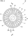
Fig. 2 is a bottom view of the bottle shown inFig. 1 . -
Fig. 3 is a sectional view taken along line X-X of the bottle shown inFig. 2 when viewed in an arrow direction. - Hereinafter, an embodiment of the present invention will be described in detail with reference to the drawings.
- As shown in
Fig. 1 , abottle 10 according to the present embodiment is formed in a bottomed tubular shape. Thebottle 10 is provided with amouth section 11, ashoulder section 12, atrunk section 13, and abottom section 14, and has a schematic constitution in which these are continuously provided in this order with central axes thereof located on a common axis. - Hereinafter, the common axis is referred to as a bottle axis O, a side directed to the
mouth section 11 in a direction of the bottle axis O is referred to as an upper side, and a side directed to thebottom section 14 is referred to as a lower side. Also, in a top view when viewed in the direction of the bottle axis O, a direction perpendicular to the bottle axis O is referred to as a bottle radial direction, and a direction revolving around the bottle axis O is referred to as a bottle circumferential direction. - Further, the
bottle 10 is integrally formed of, for instance, a synthetic resin material such as polyethylene terephthalate. Thisbottle 10 may be used as a so-called heat-resistant bottle that is filled with a content, a temperature of which is, for instance, 75°C to 87°C, and particularly about 85°C or more. - The
mouth section 11 is formed in a tubular shape, and a cap (not shown) is mounted on themouth section 11. Further, each of themouth section 11, theshoulder section 12, thetrunk section 13, and thebottom section 14 has a circular shape when viewed in a cross section perpendicular to the bottle axis O. - The
shoulder section 12 is continuous to a lower end of themouth section 11, and a diameter thereof is gradually increased toward the lower side. A plurality oflongitudinal grooves 12a, which extend along an outer circumferential surface of theshoulder section 12 in the direction of the bottle axis O, are formed in theshoulder section 12 at intervals in a circumferential direction. - The
trunk section 13 is formed in a tubular shape. A plurality ofpartition grooves trunk section 13 at intervals in the direction of the bottle axis O. Thepartition grooves first partition grooves 16a and asecond partition groove 16b. - The
first partition grooves 16a are provided in a pair at an interval in the direction of the bottle axis O. Thefirst partition grooves 16a separately partition anupper end 13a and alower end 13b in the direction of the bottle axis O, and anintermediate part 13c located between both of these ends. The singlesecond partition groove 16b is disposed in the middle of theintermediate part 13c in the direction of the bottle axis O. Thesecond partition groove 16b partitions theintermediate part 13c in the direction of the bottle axis O. Thesecond partition groove 16b is deeper than thefirst partition grooves 16a. - The opposite ends 13a and 13b of the
trunk section 13 in the direction of the bottle axis O are respectively formed with a plurality ofnarrow grooves 16c, which continuously extend throughout the circumference, at an interval in the direction of the bottle axis O. - The
intermediate part 13c of thetrunk section 13 in the direction of the bottle axis O is formed with a plurality ofcircumferential grooves 16d, which continuously extend throughout the circumference, at intervals in the direction of the bottle axis O. Thecircumferential grooves 16d are formed in respective portions (hereinafter referred to as "partition portions") into which theintermediate part 13c is partitioned with thesecond partition groove 16b in a plural number, and in the same number as in the shown example. - The
circumferential grooves 16d have a wider width than thenarrow groove 16c. Thecircumferential grooves 16d are deeper than thenarrow groove 16c. The plurality ofcircumferential grooves 16d are disposed over the whole areas of the respective partition portions of theintermediate part 13c of thetrunk section 13 in the direction of the bottle axis O at intervals in the direction of the bottle axis O. Thecircumferential grooves 16d have waveforms that have the same shapes and sizes and periodically extend in a circumferential direction while being bent in the direction of the bottle axis O in a side view of thetrunk section 13. Thecircumferential grooves 16d adjacent to each other in the direction of the bottle axis O are separated from each other throughout the circumference in the direction of the bottle axis O. Phases of thecircumferential grooves 16d adjacent to each other in the direction of the bottle axis O are shifted from each other. - The
bottom section 14 is formed in the shape of a cup that is continuous to thelower end 13b of thetrunk section 13 and blocks a lower end opening of thetrunk section 13. To be specific, thebottom section 14 is formed in the shape of a cup that is provided with aheel part 17, an upper end opening of which is connected to the lower end opening of thetrunk section 13, and abottom wall section 19 which blocks a lower end opening of theheel part 17 and an outer circumferential edge of which becomes acontact part 18. - As shown in
Figs. 2 and3 , thecontact part 18 of thebottom wall section 19 is formed in the shape of a ring that is disposed coaxially with the bottle axis O, and continuously extends throughout the circumference in the bottle circumferential direction. Adeformable tube part 20 that is of a multilevel topped tubular shape and blocks the inside of thecontact part 18 is provided upright at thecontact part 18. - Of tubular parts constituting this
deformable tube part 20, an upper tubular part located at an upper side (an inner side in the direction of the bottle axis) is deformed to be relatively displaced upward relative to a lower tubular part located at a lower side (an outer side in the direction of the bottle axis), and thereby thedeformable tube part 20 exhibits reduced-pressure absorbing performance. - As shown in
Fig. 3 , thedeformable tube part 20 is provided with a risingcircumferential wall part 21 that is continuous to thecontact part 18 from the inner side in the bottle radial direction and extends upward, an annularmovable wall part 22 that protrudes from an upper end of the risingcircumferential wall part 21 toward the inner side in the bottle radial direction, and a depressedcircumferential wall part 23 that extends upward from an inner end of themovable wall part 22 in the bottle radial direction. - An
uneven part 21a is formed at the risingcircumferential wall part 21 throughout the circumference. Theuneven part 21a is configured such that a plurality of protrusions formed in a curved surface shape protruding toward the inner side in the bottle radial direction are arranged at intervals in the bottle circumferential direction. - The
movable wall part 22 is formed in a curved surface shape protruding downward, and gradually extends downward from the outer side toward the inner side in the bottle radial direction. Themovable wall part 22 and the risingcircumferential wall part 21 are connected via a curved surface part (a portion connected with the rising circumferential wall part) 25 protruding upward. Themovable wall part 22 is configured to be movable relative to thecurved surface part 25 to displace the depressedcircumferential wall part 23 toward the upper side. - As shown in
Figs. 2 and3 , themovable wall part 22 has a plurality ofribs 29 that are radially arranged around the bottle axis O. Theribs 29 are configured such that a plurality ofrecesses 29a recessed upward in a curved surface shape are intermittently arranged in the bottle radial direction. Inner ends of theribs 29 in the bottle radial direction may be located within themovable wall part 22 or within the depressedcircumferential wall part 23. - In the present embodiment here, a density of the
movable wall part 22 is equal to or more than 1.374 g/cm3, and a portion of themovable wall part 22 which has the lowest density has a density of 1.374 g/cm3 or more. - The depressed
circumferential wall part 23 is disposed coaxially with the bottle axis O, and atop wall 24 disposed coaxially with the bottle axis O is connected to an upper end of the depressedcircumferential wall part 23. The depressedcircumferential wall part 23 and thetop wall 24 have a topped tubular shape as a whole. The depressedcircumferential wall part 23 is formed in a cylindrical shape. Thetop wall 24 is formed in a tabular shape. - As shown in
Fig. 3 , the depressedcircumferential wall part 23 is formed in the shape of a multilevel tube, a diameter of which is gradually increased from an upper side toward a lower side thereof. The depressedcircumferential wall part 23 is provided with alower tube part 23a, a diameter of which is gradually reduced from the inner end of themovable wall part 22 in the bottle radial direction toward an upper side thereof, anupper tube part 23b, a diameter of which is gradually increased from an outer circumferential edge of thetop wall 24 toward a lower side thereof and which has a smaller diameter than thelower tube part 23a, and anannular step part 23c that connects together thetube parts - In a longitudinal sectional view of the
deformable tube part 20, thelower tube part 23a and theupper tube part 23b extend in a straight line shape, and are inclined with respect to the bottle axis O. In the longitudinal sectional view, an inclined angle of thelower tube part 23a is greater than that of theupper tube part 23b. - The
lower tube part 23a is connected to the inner end of themovable wall part 22 in the bottle radial direction via acurved surface part 26 protruding downward. Thecurved surface part 26 faces the inner side in the bottle radial direction, and protrudes obliquely downward. Thecurved surface part 26 smoothly connects themovable wall part 22 and thelower tube part 23a without a level difference. A connected portion between theupper tube part 23b and thetop wall 24 faces the outer side in the bottle radial direction, and is formed in the shape of a curved surface that protrudes obliquely upward. - The
annular step part 23c has inner and outer surfaces facing the direction of the bottle axis O, and is formed in a tabular shape. Theannular step part 23c is located at a height equal to that of the upper end of the risingcircumferential wall part 21 in the direction of the bottle axis O. - An outer circumferential edge of the
annular step part 23c is provided with aconcave strip part 27 recessed upward. Theconcave strip part 27 continuously extends throughout the circumference in a circumferential direction. Theconcave strip part 27 is formed in the shape of a curved surface protruding upward. An outer circumferential surface of theconcave strip part 27 which faces the inner side in the bottle radial direction is smoothly continuous to thelower tube part 23a without a level difference. A connected portion between theannular step part 23c and theupper tube part 23b faces the inner side in the bottle radial direction, and is formed in the shape of a curved surface that protrudes obliquely downward. - In the
bottle 10, when an internal pressure of thebottle 10 varies, themovable wall part 22 is turned upward to allow the variation in the internal pressure to be absorbed. Thereby, it is possible to suppress deformation of each of theshoulder section 12 and thetrunk section 13 in the bottle radial direction. - Next, an example of a method for manufacturing the
bottle 10 will be described. This manufacturing method has a primary blow molding process of carrying out biaxial stretch blow molding on a preform to obtain a primary intermediate molded article, a heat treatment process of heating the primary intermediate molded article to be forcibly shrunken and molded into a secondary intermediate molded article, and a secondary blow molding process of carrying out blow molding on the secondary intermediate molded article to obtain thebottle 10. - The primary blow molding process is carried out in analogy with, for instance, typical biaxial stretch blow molding. At this point, a main body part that include portions other than a portion becoming the mouth section in the perform, i.e. portions becoming the
shoulder section 12, thetrunk section 13, and thebottom section 14 is stretched and molded. - In the heat treatment process, internal residual stress occurring in the primary intermediate molded article is forcibly removed, and crystallization of the primary intermediate molded article is accelerated. Further, in this heat treatment process, a metal mold for the primary blow molding process may be used. At this point, in the primary intermediate molded article, according to internal residual stress generated in each of portions molded by stretching the main body part of the preform (hereinafter referred to as "stretched and molded portion"), the stretched and molded portion is freely shrunken and deformed to forcibly remove the internal residual stress. Thereby, the secondary intermediate molded article is molded.
- Further, the stretched and molded portion in the secondary intermediate molded article has a size equal to or slightly smaller than a bottle
main body 15 including theshoulder section 12, thetrunk section 13, and thebottom section 14 in thebottle 10. The size of the stretched and molded portion in the secondary intermediate molded article may be adjusted, for instance, by setting a magnification of stretch molding from the preform into the primary intermediate molded article, and dimensions of the primary intermediate molded article. - The secondary blow molding process is carried out similar to typical biaxial stretch blow molding. At this point, a stretching magnification is smaller compared to the primary blow molding process of the stretched and molded portion in the secondary intermediate molded article.
- Thereby, the
bottle 10 is formed from the preform. - As described above, according to the method for manufacturing the bottle according to the present embodiment, the
bottle 10 is formed by so-called double blow molding that has the primary blow molding process, the heat treatment process, and the secondary blow molding process. Therefore, in comparison with a case in which so-called single blow molding in which thebottle 10 is formed by single biaxial stretch blow molding is employed, a density of thedeformable tube part 20 can be improved. Thereby, even if thedeformable tube part 20 is thinned, it is possible, for instance, to maintain a density of themovable wall part 22, and secure heat resistance of thedeformable tube part 20. - Also, the density of the
movable wall part 22 is equal to or more than 1.374 g/cm3, and the density of themovable wall part 22 that is a portion of thedeformable tube part 20 which is easy to be positively displaced is increased to a certain level or more. Thereby, it is possible to efficiently secure the heat resistance of thedeformable tube part 20. - Also, as described above, the double blow molding is adopted to improve the density of the
deformable tube part 20, and thereby the heat resistance of thedeformable tube part 20 can be secured. Accordingly, in comparison with a case in which the single blow molding is adopted and then thebottle 10 imparting thedeformable tube part 20 with equivalent heat resistance is formed, a temperature of the bottom mold can be kept low. Thereby, the reduced-pressure absorbing performance caused by thedeformable tube part 20 can also be secured. - The technical scope of the present invention is not limited to the aforementioned embodiment, but the present invention may be modified in various ways without departing from the gist of the present invention.
- The
longitudinal grooves 12a, thepartition grooves narrow groove 16c, and thecircumferential grooves 16d are dispensable. - The rising
circumferential wall part 21 may be appropriately modified to, for instance, extend in parallel in the direction of the bottle axis O or extend to be inclined with respect to the bottle axis O. - The
movable wall part 22 may be appropriately modified to, for instance, protrude in parallel in the bottle radial direction. - The synthetic resin material of which the
bottle 10 is formed is not limited to polyethylene terephthalate, but it may be appropriately modified to, for instance, polyethylene naphthalate, amorphous polyester, or the like, or a blend material thereof. - The
bottle 10 is not limited to a single-layered structure, but it may be a stacked structure having an intermediate layer. This intermediate layer may include, for instance, a layer formed of a resin material having a gas barrier characteristic, a layer formed of a recycled material, or a layer formed of a resin material having oxygen absorbability. - In the aforementioned embodiment, the shape of each of the
shoulder section 12, thetrunk section 13, and thebottom section 14 when viewed in the cross section perpendicular to the bottle axis O is set as the circular shape, but without being limited thereto, it may be appropriately modified to, for instance, be a polygonal shape. - In addition, without departing from the gist of the present invention, the components in the aforementioned embodiment may be appropriately substituted with well-known components, and furthermore, they may be appropriately combined with the aforementioned modifications.
- Next, a verification test for verifying the operation and effects described above will be described.
- In this verification test, as Comparative Examples 1 to 4 and Embodiment 1, five bottles having the structure shown in the aforementioned embodiment were formed by making molding conditions different from one another. The molding conditions, and so on of each bottle are presented in Table 1 below.
[Table 1] Comparative Example Embodiment 1 2 3 4 1 Molding method Single blow Double blow Temperature of bottom mold 50°C 120°C 50°C Average value of thicknesses of deformable tube part (mm) 0.41 0.44 0.49 0.40 0.32 Weight of deformable tube part (g) 2.0 2.4 3.2 2.0 1.84 Density at outer circumferential portion of movable wall part (g/cm3) 1.369 1.375 1.373 Density at inner circumferential portion of movable wall part (g/cm3) 1.375 1.374 1.375 Heat-resistant temperature 70°C 87°C 87°C - As presented in Table 1, in Comparative Examples 1 to 4, a bottle was formed from a preform by single blow molding, i.e. single biaxial stretch blow molding. In Embodiment 1, a bottle was formed by the method for manufacturing the bottle, which has been described in the aforementioned embodiment.
- In Comparative Examples 1 to 3, a temperature of the bottom mold was set to 50°C. In Comparative Example 4, a temperature of the bottom mold was set to 120°C. In Embodiment 1, a temperature of the bottom mold in a secondary blow molding process was set to 50°C.
- Further, an average value of thicknesses of the deformable tube part and weight (mass) of the deformable tube part are as presented in Table 1. The bottles according to Comparative Examples 1 to 4 and Embodiment 1 have the same structures, but they are different from one another in the thickness and weight of the deformable tube part.
- With respect to each of Comparative Examples 1 to 4 and Embodiment 1, a density at the outer circumferential portion of the movable wall part, a density at the inner circumferential portion of the movable wall part, and a heat-resistant temperature are as presented in Table 1. The heat-resistant temperature refers to an upper limit of a temperature of a content, at which, when the content is filled in the bottle, the deformable tube part of the bottle can absorb a reduced pressure without deformation during cooling.
- It was ascertained from this result by comparing the density at the outer circumferential portion of the movable wall part of each of Comparative Examples 1 to 3 with that of Comparative Example 4, if the temperature of the bottom mold is raised, the density of the movable wall part can be increased. Also, as a result, it was ascertained that the heat-resistant temperature was also raised.
- Thus, it was ascertained that, after Embodiment 1 was added to Comparative Examples 1 to 3 and Comparative Example 4, the densities at the outer circumferential portions of the movable wall parts were compared with one another, and thereby the density of the movable wall part could be increased without raising the temperature of the bottom mold when the bottle was formed by double blow molding. Also, as a result, it was ascertained that the heat-resistant temperature was also raised.
- With respect to each of Comparative Examples 1 to 4 and Embodiment 1, reduced-pressure absorbing performance (not set forth in Table 1) was ascertained. As a result, Comparative Examples 1 to 3 and Embodiment 1 exhibited equivalent reduced-pressure absorbing performance, but Comparative Example 4 had a worse reduced-pressure absorbing performance than Comparative Examples 1 to 3 and Embodiment 1. It was ascertained from this result that the bottle was formed by double blow molding, the temperature of the bottom mold was kept low, and thereby the reduced-pressure absorbing performance was secured.
- According to the present invention, the deformable tube part can be thinned while securing the reduced-pressure absorbing performance caused by the deformable tube part and the heat resistance of the deformable tube part.
-
- 10 Bottle
- 18 Contact part
- 19 Bottom wall section
- 20 Deformable tube part
- 21 Rising circumferential wall part
- 22 Movable wall part
- 23 Depressed circumferential wall part
- 25 Curved surface part (connected portion connected with rising circumferential wall part)
- O bottle axis
Claims (2)
- A method for manufacturing a bottle including forming the bottle that is formed in a bottomed tubular shape and has a bottom wall section provided with a contact part positioned at an outer circumferential edge thereof and a deformable tube part that is of a multilevel topped tubular shape, is provided upright at the contact part, and blocks an inside of the contact part;
the deformable tube part includes a rising circumferential wall part that is continuous to the contact part from an inner side in a bottle radial direction and extends toward an upper side that is an inner side in a direction of a bottle axis, an annular movable wall part that protrudes from an upper end of the rising circumferential wall part toward the inner side in the bottle radial direction, and a depressed circumferential wall part that extends upward from an inner end of the movable wall part in the bottle radial direction;
the movable wall part is arranged to be movable upward relative to a connected portion connected with the rising circumferential wall part along with the depressed circumferential wall part;
the method comprising:a primary blow molding process of performing biaxial stretch blow molding on a preform to obtain a primary intermediate molded article;a heat treatment process of heating the primary intermediate molded article to be forcibly shrunken and molded into a secondary intermediate molded article; anda secondary blow molding process of performing blow molding on the secondary intermediate molded article to obtain the bottle. - The method according to claim 1, wherein a density of the movable wall part is equal to or more than 1.374 g/cm3.
Applications Claiming Priority (2)
| Application Number | Priority Date | Filing Date | Title |
|---|---|---|---|
| JP2014073266A JP6457191B2 (en) | 2014-03-31 | 2014-03-31 | Bottle manufacturing method |
| PCT/JP2015/051847 WO2015151559A1 (en) | 2014-03-31 | 2015-01-23 | Method for manufacturing bottle |
Publications (3)
| Publication Number | Publication Date |
|---|---|
| EP3127680A1 true EP3127680A1 (en) | 2017-02-08 |
| EP3127680A4 EP3127680A4 (en) | 2017-11-22 |
| EP3127680B1 EP3127680B1 (en) | 2020-03-11 |
Family
ID=54239902
Family Applications (1)
| Application Number | Title | Priority Date | Filing Date |
|---|---|---|---|
| EP15774242.0A Active EP3127680B1 (en) | 2014-03-31 | 2015-01-23 | Method for manufacturing a bottle |
Country Status (6)
| Country | Link |
|---|---|
| US (1) | US10099811B2 (en) |
| EP (1) | EP3127680B1 (en) |
| JP (1) | JP6457191B2 (en) |
| AU (1) | AU2015241913B2 (en) |
| CA (1) | CA2933837C (en) |
| WO (1) | WO2015151559A1 (en) |
Families Citing this family (11)
| Publication number | Priority date | Publication date | Assignee | Title |
|---|---|---|---|---|
| CN104703776A (en) * | 2012-08-31 | 2015-06-10 | 依云矿泉水股份有限公司 | Bottle, method of making the same and use of FDCA and diol monomers in such bottle |
| USD802425S1 (en) * | 2015-11-09 | 2017-11-14 | Cj Cheiljedang Corp. | Bottle |
| USD808813S1 (en) * | 2015-12-28 | 2018-01-30 | The Coca-Cola Company | Bottle |
| USD802424S1 (en) * | 2016-01-13 | 2017-11-14 | Cj Cheiljedang Corp. | Bottle |
| USD810575S1 (en) * | 2016-03-04 | 2018-02-20 | Aquawell Group AG | Bottle |
| USD811230S1 (en) * | 2016-03-04 | 2018-02-27 | Aquawell Group AG | Bottle |
| TWI680851B (en) * | 2017-11-23 | 2020-01-01 | 三弘實業有限公司 | Pouch manufacturing method and its mold |
| JP7278971B2 (en) * | 2018-01-18 | 2023-05-22 | 日精エー・エス・ビー機械株式会社 | container |
| MX2022011301A (en) * | 2020-03-11 | 2022-11-14 | Niagara Bottling Llc | Offset wave groove bottle. |
| US20260021623A1 (en) * | 2022-06-21 | 2026-01-22 | Amcor Rigid Packaging Usa, Llc | Vacuum absorbing, blow molded, container base |
| USD1126002S1 (en) | 2024-10-08 | 2026-05-12 | Co2Pac Limited | Container |
Family Cites Families (9)
| Publication number | Priority date | Publication date | Assignee | Title |
|---|---|---|---|---|
| US5352402A (en) * | 1989-10-23 | 1994-10-04 | Nissei Asb Machine Co., Ltd. | Method and apparatus for manufacturing biaxially oriented, thermally stable, blown containers |
| DE69025451T2 (en) | 1989-10-23 | 1996-07-04 | Nissei Asb Machine Co Ltd | Method of manufacturing biaxially oriented containers and apparatus for manufacturing the same |
| JPH0813498B2 (en) * | 1992-02-29 | 1996-02-14 | 日精エー・エス・ビー機械株式会社 | Molding method for heat-resistant container |
| FR2730471B1 (en) | 1995-02-09 | 1997-04-25 | Sidel Sa | CONTAINER, SUCH AS BOTTLE, WITH SELF-CONTAINING BOTTLE AND METHODS OF MAKING SAME |
| US6720047B2 (en) | 2000-05-02 | 2004-04-13 | Toyo Seikan Kaisha, Ltd. | Heat resistant blow molded containers |
| JP4186431B2 (en) * | 2000-05-02 | 2008-11-26 | 東洋製罐株式会社 | Stretch blow molded container |
| JP2002166916A (en) * | 2000-11-29 | 2002-06-11 | Yoshino Kogyosho Co Ltd | Biaxially stretch blow molded lightweight bottle container made of synthetic resin and method of manufacturing the same |
| EP2853501B1 (en) | 2008-11-27 | 2017-03-22 | Yoshino Kogyosho Co., Ltd. | Synthetic resin bottle |
| ES2685125T3 (en) * | 2011-03-29 | 2018-10-05 | Amcor Group Gmbh | Procedure to form a container |
-
2014
- 2014-03-31 JP JP2014073266A patent/JP6457191B2/en active Active
-
2015
- 2015-01-23 AU AU2015241913A patent/AU2015241913B2/en active Active
- 2015-01-23 CA CA2933837A patent/CA2933837C/en active Active
- 2015-01-23 WO PCT/JP2015/051847 patent/WO2015151559A1/en not_active Ceased
- 2015-01-23 US US15/103,576 patent/US10099811B2/en active Active
- 2015-01-23 EP EP15774242.0A patent/EP3127680B1/en active Active
Also Published As
| Publication number | Publication date |
|---|---|
| EP3127680B1 (en) | 2020-03-11 |
| AU2015241913A1 (en) | 2016-06-30 |
| EP3127680A4 (en) | 2017-11-22 |
| US10099811B2 (en) | 2018-10-16 |
| WO2015151559A1 (en) | 2015-10-08 |
| AU2015241913A8 (en) | 2016-07-14 |
| CA2933837C (en) | 2021-07-13 |
| JP6457191B2 (en) | 2019-01-23 |
| CA2933837A1 (en) | 2015-10-08 |
| US20160304232A1 (en) | 2016-10-20 |
| JP2015193410A (en) | 2015-11-05 |
| AU2015241913B2 (en) | 2019-03-14 |
Similar Documents
| Publication | Publication Date | Title |
|---|---|---|
| EP3127680B1 (en) | Method for manufacturing a bottle | |
| US11352162B2 (en) | Plastics material bottle with intersecting tension bands | |
| EP3290345B1 (en) | Synthetic resin container | |
| JP2003285814A (en) | Synthetic resin bottle | |
| JP6788389B2 (en) | Blow Molded Preforms for Multiple Bottles and Multiple Bottles | |
| US11136167B2 (en) | Plastic container with threaded neck finish | |
| JP6648006B2 (en) | Synthetic resin bottle | |
| CA3040674A1 (en) | Bottle | |
| JP2017210266A (en) | Synthetic resin blow molded bottle | |
| JP6707884B2 (en) | Synthetic resin container | |
| JP6389359B2 (en) | Bottle manufacturing method | |
| JP5631183B2 (en) | preform | |
| JP2013144560A (en) | Synthetic resin made container | |
| JP5434634B2 (en) | Plastic container | |
| JP2016145074A (en) | Synthetic resin container | |
| JP4525922B2 (en) | Polyester resin container and molding method thereof | |
| JP7833941B2 (en) | Round bottle made of synthetic resin | |
| JP5453669B2 (en) | Synthetic resin square housing | |
| JP5349780B2 (en) | Packaging container | |
| JP6670573B2 (en) | A bottle with a panel formed on the body | |
| JP6902934B2 (en) | Blow bottle | |
| JP6678047B2 (en) | Preform for blow molding | |
| JP7158181B2 (en) | square bottle | |
| JP6367641B2 (en) | Composite container and manufacturing method thereof | |
| JP5666506B2 (en) | Plastic bottle |
Legal Events
| Date | Code | Title | Description |
|---|---|---|---|
| STAA | Information on the status of an ep patent application or granted ep patent |
Free format text: STATUS: THE INTERNATIONAL PUBLICATION HAS BEEN MADE |
|
| PUAI | Public reference made under article 153(3) epc to a published international application that has entered the european phase |
Free format text: ORIGINAL CODE: 0009012 |
|
| STAA | Information on the status of an ep patent application or granted ep patent |
Free format text: STATUS: REQUEST FOR EXAMINATION WAS MADE |
|
| 17P | Request for examination filed |
Effective date: 20160905 |
|
| AK | Designated contracting states |
Kind code of ref document: A1 Designated state(s): AL AT BE BG CH CY CZ DE DK EE ES FI FR GB GR HR HU IE IS IT LI LT LU LV MC MK MT NL NO PL PT RO RS SE SI SK SM TR |
|
| AX | Request for extension of the european patent |
Extension state: BA ME |
|
| DAX | Request for extension of the european patent (deleted) | ||
| A4 | Supplementary search report drawn up and despatched |
Effective date: 20171020 |
|
| RIC1 | Information provided on ipc code assigned before grant |
Ipc: B29C 49/48 20060101ALI20171016BHEP Ipc: B65D 1/02 20060101ALI20171016BHEP Ipc: B29C 49/08 20060101AFI20171016BHEP Ipc: B29C 49/54 20060101ALI20171016BHEP Ipc: B29C 33/42 20060101ALI20171016BHEP |
|
| REG | Reference to a national code |
Ref country code: DE Ref legal event code: R079 Ref document number: 602015048646 Country of ref document: DE Free format text: PREVIOUS MAIN CLASS: B29C0049080000 Ipc: B29C0049180000 |
|
| GRAP | Despatch of communication of intention to grant a patent |
Free format text: ORIGINAL CODE: EPIDOSNIGR1 |
|
| STAA | Information on the status of an ep patent application or granted ep patent |
Free format text: STATUS: GRANT OF PATENT IS INTENDED |
|
| RIC1 | Information provided on ipc code assigned before grant |
Ipc: B65D 1/02 20060101ALI20191031BHEP Ipc: B29K 67/00 20060101ALN20191031BHEP Ipc: B29C 49/54 20060101ALI20191031BHEP Ipc: B29C 49/18 20060101AFI20191031BHEP Ipc: B29C 49/08 20060101ALI20191031BHEP Ipc: B29C 49/64 20060101ALI20191031BHEP Ipc: B29C 49/48 20060101ALN20191031BHEP |
|
| RIN1 | Information on inventor provided before grant (corrected) |
Inventor name: SUZUKI TAKANORI Inventor name: YOSHII KOJI |
|
| INTG | Intention to grant announced |
Effective date: 20191118 |
|
| GRAS | Grant fee paid |
Free format text: ORIGINAL CODE: EPIDOSNIGR3 |
|
| GRAA | (expected) grant |
Free format text: ORIGINAL CODE: 0009210 |
|
| STAA | Information on the status of an ep patent application or granted ep patent |
Free format text: STATUS: THE PATENT HAS BEEN GRANTED |
|
| AK | Designated contracting states |
Kind code of ref document: B1 Designated state(s): AL AT BE BG CH CY CZ DE DK EE ES FI FR GB GR HR HU IE IS IT LI LT LU LV MC MK MT NL NO PL PT RO RS SE SI SK SM TR |
|
| REG | Reference to a national code |
Ref country code: GB Ref legal event code: FG4D |
|
| REG | Reference to a national code |
Ref country code: CH Ref legal event code: EP |
|
| REG | Reference to a national code |
Ref country code: AT Ref legal event code: REF Ref document number: 1242586 Country of ref document: AT Kind code of ref document: T Effective date: 20200315 |
|
| REG | Reference to a national code |
Ref country code: IE Ref legal event code: FG4D |
|
| REG | Reference to a national code |
Ref country code: DE Ref legal event code: R096 Ref document number: 602015048646 Country of ref document: DE |
|
| PG25 | Lapsed in a contracting state [announced via postgrant information from national office to epo] |
Ref country code: RS Free format text: LAPSE BECAUSE OF FAILURE TO SUBMIT A TRANSLATION OF THE DESCRIPTION OR TO PAY THE FEE WITHIN THE PRESCRIBED TIME-LIMIT Effective date: 20200311 Ref country code: FI Free format text: LAPSE BECAUSE OF FAILURE TO SUBMIT A TRANSLATION OF THE DESCRIPTION OR TO PAY THE FEE WITHIN THE PRESCRIBED TIME-LIMIT Effective date: 20200311 Ref country code: NO Free format text: LAPSE BECAUSE OF FAILURE TO SUBMIT A TRANSLATION OF THE DESCRIPTION OR TO PAY THE FEE WITHIN THE PRESCRIBED TIME-LIMIT Effective date: 20200611 |
|
| REG | Reference to a national code |
Ref country code: NL Ref legal event code: MP Effective date: 20200311 |
|
| PG25 | Lapsed in a contracting state [announced via postgrant information from national office to epo] |
Ref country code: BG Free format text: LAPSE BECAUSE OF FAILURE TO SUBMIT A TRANSLATION OF THE DESCRIPTION OR TO PAY THE FEE WITHIN THE PRESCRIBED TIME-LIMIT Effective date: 20200611 Ref country code: SE Free format text: LAPSE BECAUSE OF FAILURE TO SUBMIT A TRANSLATION OF THE DESCRIPTION OR TO PAY THE FEE WITHIN THE PRESCRIBED TIME-LIMIT Effective date: 20200311 Ref country code: LV Free format text: LAPSE BECAUSE OF FAILURE TO SUBMIT A TRANSLATION OF THE DESCRIPTION OR TO PAY THE FEE WITHIN THE PRESCRIBED TIME-LIMIT Effective date: 20200311 Ref country code: HR Free format text: LAPSE BECAUSE OF FAILURE TO SUBMIT A TRANSLATION OF THE DESCRIPTION OR TO PAY THE FEE WITHIN THE PRESCRIBED TIME-LIMIT Effective date: 20200311 Ref country code: GR Free format text: LAPSE BECAUSE OF FAILURE TO SUBMIT A TRANSLATION OF THE DESCRIPTION OR TO PAY THE FEE WITHIN THE PRESCRIBED TIME-LIMIT Effective date: 20200612 |
|
| REG | Reference to a national code |
Ref country code: LT Ref legal event code: MG4D |
|
| PG25 | Lapsed in a contracting state [announced via postgrant information from national office to epo] |
Ref country code: NL Free format text: LAPSE BECAUSE OF FAILURE TO SUBMIT A TRANSLATION OF THE DESCRIPTION OR TO PAY THE FEE WITHIN THE PRESCRIBED TIME-LIMIT Effective date: 20200311 |
|
| PG25 | Lapsed in a contracting state [announced via postgrant information from national office to epo] |
Ref country code: PT Free format text: LAPSE BECAUSE OF FAILURE TO SUBMIT A TRANSLATION OF THE DESCRIPTION OR TO PAY THE FEE WITHIN THE PRESCRIBED TIME-LIMIT Effective date: 20200805 Ref country code: SK Free format text: LAPSE BECAUSE OF FAILURE TO SUBMIT A TRANSLATION OF THE DESCRIPTION OR TO PAY THE FEE WITHIN THE PRESCRIBED TIME-LIMIT Effective date: 20200311 Ref country code: IS Free format text: LAPSE BECAUSE OF FAILURE TO SUBMIT A TRANSLATION OF THE DESCRIPTION OR TO PAY THE FEE WITHIN THE PRESCRIBED TIME-LIMIT Effective date: 20200711 Ref country code: RO Free format text: LAPSE BECAUSE OF FAILURE TO SUBMIT A TRANSLATION OF THE DESCRIPTION OR TO PAY THE FEE WITHIN THE PRESCRIBED TIME-LIMIT Effective date: 20200311 Ref country code: CZ Free format text: LAPSE BECAUSE OF FAILURE TO SUBMIT A TRANSLATION OF THE DESCRIPTION OR TO PAY THE FEE WITHIN THE PRESCRIBED TIME-LIMIT Effective date: 20200311 Ref country code: LT Free format text: LAPSE BECAUSE OF FAILURE TO SUBMIT A TRANSLATION OF THE DESCRIPTION OR TO PAY THE FEE WITHIN THE PRESCRIBED TIME-LIMIT Effective date: 20200311 Ref country code: SM Free format text: LAPSE BECAUSE OF FAILURE TO SUBMIT A TRANSLATION OF THE DESCRIPTION OR TO PAY THE FEE WITHIN THE PRESCRIBED TIME-LIMIT Effective date: 20200311 Ref country code: EE Free format text: LAPSE BECAUSE OF FAILURE TO SUBMIT A TRANSLATION OF THE DESCRIPTION OR TO PAY THE FEE WITHIN THE PRESCRIBED TIME-LIMIT Effective date: 20200311 |
|
| REG | Reference to a national code |
Ref country code: AT Ref legal event code: MK05 Ref document number: 1242586 Country of ref document: AT Kind code of ref document: T Effective date: 20200311 |
|
| REG | Reference to a national code |
Ref country code: DE Ref legal event code: R097 Ref document number: 602015048646 Country of ref document: DE |
|
| PLBE | No opposition filed within time limit |
Free format text: ORIGINAL CODE: 0009261 |
|
| STAA | Information on the status of an ep patent application or granted ep patent |
Free format text: STATUS: NO OPPOSITION FILED WITHIN TIME LIMIT |
|
| PG25 | Lapsed in a contracting state [announced via postgrant information from national office to epo] |
Ref country code: DK Free format text: LAPSE BECAUSE OF FAILURE TO SUBMIT A TRANSLATION OF THE DESCRIPTION OR TO PAY THE FEE WITHIN THE PRESCRIBED TIME-LIMIT Effective date: 20200311 Ref country code: AT Free format text: LAPSE BECAUSE OF FAILURE TO SUBMIT A TRANSLATION OF THE DESCRIPTION OR TO PAY THE FEE WITHIN THE PRESCRIBED TIME-LIMIT Effective date: 20200311 Ref country code: ES Free format text: LAPSE BECAUSE OF FAILURE TO SUBMIT A TRANSLATION OF THE DESCRIPTION OR TO PAY THE FEE WITHIN THE PRESCRIBED TIME-LIMIT Effective date: 20200311 Ref country code: IT Free format text: LAPSE BECAUSE OF FAILURE TO SUBMIT A TRANSLATION OF THE DESCRIPTION OR TO PAY THE FEE WITHIN THE PRESCRIBED TIME-LIMIT Effective date: 20200311 |
|
| 26N | No opposition filed |
Effective date: 20201214 |
|
| PG25 | Lapsed in a contracting state [announced via postgrant information from national office to epo] |
Ref country code: SI Free format text: LAPSE BECAUSE OF FAILURE TO SUBMIT A TRANSLATION OF THE DESCRIPTION OR TO PAY THE FEE WITHIN THE PRESCRIBED TIME-LIMIT Effective date: 20200311 Ref country code: PL Free format text: LAPSE BECAUSE OF FAILURE TO SUBMIT A TRANSLATION OF THE DESCRIPTION OR TO PAY THE FEE WITHIN THE PRESCRIBED TIME-LIMIT Effective date: 20200311 |
|
| PG25 | Lapsed in a contracting state [announced via postgrant information from national office to epo] |
Ref country code: MC Free format text: LAPSE BECAUSE OF FAILURE TO SUBMIT A TRANSLATION OF THE DESCRIPTION OR TO PAY THE FEE WITHIN THE PRESCRIBED TIME-LIMIT Effective date: 20200311 |
|
| REG | Reference to a national code |
Ref country code: CH Ref legal event code: PL |
|
| PG25 | Lapsed in a contracting state [announced via postgrant information from national office to epo] |
Ref country code: LU Free format text: LAPSE BECAUSE OF NON-PAYMENT OF DUE FEES Effective date: 20210123 |
|
| REG | Reference to a national code |
Ref country code: BE Ref legal event code: MM Effective date: 20210131 |
|
| PG25 | Lapsed in a contracting state [announced via postgrant information from national office to epo] |
Ref country code: LI Free format text: LAPSE BECAUSE OF NON-PAYMENT OF DUE FEES Effective date: 20210131 Ref country code: CH Free format text: LAPSE BECAUSE OF NON-PAYMENT OF DUE FEES Effective date: 20210131 |
|
| PG25 | Lapsed in a contracting state [announced via postgrant information from national office to epo] |
Ref country code: IE Free format text: LAPSE BECAUSE OF NON-PAYMENT OF DUE FEES Effective date: 20210123 |
|
| PG25 | Lapsed in a contracting state [announced via postgrant information from national office to epo] |
Ref country code: BE Free format text: LAPSE BECAUSE OF NON-PAYMENT OF DUE FEES Effective date: 20210131 |
|
| PG25 | Lapsed in a contracting state [announced via postgrant information from national office to epo] |
Ref country code: HU Free format text: LAPSE BECAUSE OF FAILURE TO SUBMIT A TRANSLATION OF THE DESCRIPTION OR TO PAY THE FEE WITHIN THE PRESCRIBED TIME-LIMIT; INVALID AB INITIO Effective date: 20150123 |
|
| PG25 | Lapsed in a contracting state [announced via postgrant information from national office to epo] |
Ref country code: CY Free format text: LAPSE BECAUSE OF FAILURE TO SUBMIT A TRANSLATION OF THE DESCRIPTION OR TO PAY THE FEE WITHIN THE PRESCRIBED TIME-LIMIT Effective date: 20200311 |
|
| PG25 | Lapsed in a contracting state [announced via postgrant information from national office to epo] |
Ref country code: MK Free format text: LAPSE BECAUSE OF FAILURE TO SUBMIT A TRANSLATION OF THE DESCRIPTION OR TO PAY THE FEE WITHIN THE PRESCRIBED TIME-LIMIT Effective date: 20200311 |
|
| PG25 | Lapsed in a contracting state [announced via postgrant information from national office to epo] |
Ref country code: TR Free format text: LAPSE BECAUSE OF FAILURE TO SUBMIT A TRANSLATION OF THE DESCRIPTION OR TO PAY THE FEE WITHIN THE PRESCRIBED TIME-LIMIT Effective date: 20200311 |
|
| PG25 | Lapsed in a contracting state [announced via postgrant information from national office to epo] |
Ref country code: MT Free format text: LAPSE BECAUSE OF FAILURE TO SUBMIT A TRANSLATION OF THE DESCRIPTION OR TO PAY THE FEE WITHIN THE PRESCRIBED TIME-LIMIT Effective date: 20200311 |
|
| PGFP | Annual fee paid to national office [announced via postgrant information from national office to epo] |
Ref country code: GB Payment date: 20241205 Year of fee payment: 11 |
|
| PGFP | Annual fee paid to national office [announced via postgrant information from national office to epo] |
Ref country code: FR Payment date: 20241209 Year of fee payment: 11 |
|
| PGFP | Annual fee paid to national office [announced via postgrant information from national office to epo] |
Ref country code: DE Payment date: 20241203 Year of fee payment: 11 |