EP3127677A1 - Injection molding mold - Google Patents
Injection molding mold Download PDFInfo
- Publication number
- EP3127677A1 EP3127677A1 EP15772956.7A EP15772956A EP3127677A1 EP 3127677 A1 EP3127677 A1 EP 3127677A1 EP 15772956 A EP15772956 A EP 15772956A EP 3127677 A1 EP3127677 A1 EP 3127677A1
- Authority
- EP
- European Patent Office
- Prior art keywords
- needle
- injection needle
- pin
- injection
- proximal end
- Prior art date
- Legal status (The legal status is an assumption and is not a legal conclusion. Google has not performed a legal analysis and makes no representation as to the accuracy of the status listed.)
- Withdrawn
Links
Images




Classifications
-
- A—HUMAN NECESSITIES
- A61—MEDICAL OR VETERINARY SCIENCE; HYGIENE
- A61M—DEVICES FOR INTRODUCING MEDIA INTO, OR ONTO, THE BODY; DEVICES FOR TRANSDUCING BODY MEDIA OR FOR TAKING MEDIA FROM THE BODY; DEVICES FOR PRODUCING OR ENDING SLEEP OR STUPOR
- A61M5/00—Devices for bringing media into the body in a subcutaneous, intra-vascular or intramuscular way; Accessories therefor, e.g. filling or cleaning devices, arm-rests
- A61M5/178—Syringes
- A61M5/31—Details
- A61M5/32—Needles; Details of needles pertaining to their connection with syringe or hub; Accessories for bringing the needle into, or holding the needle on, the body; Devices for protection of needles
- A61M5/34—Constructions for connecting the needle, e.g. to syringe nozzle or needle hub
-
- A—HUMAN NECESSITIES
- A61—MEDICAL OR VETERINARY SCIENCE; HYGIENE
- A61M—DEVICES FOR INTRODUCING MEDIA INTO, OR ONTO, THE BODY; DEVICES FOR TRANSDUCING BODY MEDIA OR FOR TAKING MEDIA FROM THE BODY; DEVICES FOR PRODUCING OR ENDING SLEEP OR STUPOR
- A61M5/00—Devices for bringing media into the body in a subcutaneous, intra-vascular or intramuscular way; Accessories therefor, e.g. filling or cleaning devices, arm-rests
- A61M5/178—Syringes
- A61M5/31—Details
- A61M5/3129—Syringe barrels
-
- B—PERFORMING OPERATIONS; TRANSPORTING
- B29—WORKING OF PLASTICS; WORKING OF SUBSTANCES IN A PLASTIC STATE IN GENERAL
- B29C—SHAPING OR JOINING OF PLASTICS; SHAPING OF MATERIAL IN A PLASTIC STATE, NOT OTHERWISE PROVIDED FOR; AFTER-TREATMENT OF THE SHAPED PRODUCTS, e.g. REPAIRING
- B29C45/00—Injection moulding, i.e. forcing the required volume of moulding material through a nozzle into a closed mould; Apparatus therefor
- B29C45/14—Injection moulding, i.e. forcing the required volume of moulding material through a nozzle into a closed mould; Apparatus therefor incorporating preformed parts or layers, e.g. injection moulding around inserts or for coating articles
- B29C45/14065—Positioning or centering articles in the mould
-
- A—HUMAN NECESSITIES
- A61—MEDICAL OR VETERINARY SCIENCE; HYGIENE
- A61M—DEVICES FOR INTRODUCING MEDIA INTO, OR ONTO, THE BODY; DEVICES FOR TRANSDUCING BODY MEDIA OR FOR TAKING MEDIA FROM THE BODY; DEVICES FOR PRODUCING OR ENDING SLEEP OR STUPOR
- A61M2207/00—Methods of manufacture, assembly or production
-
- A—HUMAN NECESSITIES
- A61—MEDICAL OR VETERINARY SCIENCE; HYGIENE
- A61M—DEVICES FOR INTRODUCING MEDIA INTO, OR ONTO, THE BODY; DEVICES FOR TRANSDUCING BODY MEDIA OR FOR TAKING MEDIA FROM THE BODY; DEVICES FOR PRODUCING OR ENDING SLEEP OR STUPOR
- A61M5/00—Devices for bringing media into the body in a subcutaneous, intra-vascular or intramuscular way; Accessories therefor, e.g. filling or cleaning devices, arm-rests
- A61M5/178—Syringes
- A61M5/28—Syringe ampoules or carpules, i.e. ampoules or carpules provided with a needle
-
- A—HUMAN NECESSITIES
- A61—MEDICAL OR VETERINARY SCIENCE; HYGIENE
- A61M—DEVICES FOR INTRODUCING MEDIA INTO, OR ONTO, THE BODY; DEVICES FOR TRANSDUCING BODY MEDIA OR FOR TAKING MEDIA FROM THE BODY; DEVICES FOR PRODUCING OR ENDING SLEEP OR STUPOR
- A61M5/00—Devices for bringing media into the body in a subcutaneous, intra-vascular or intramuscular way; Accessories therefor, e.g. filling or cleaning devices, arm-rests
- A61M5/178—Syringes
- A61M5/31—Details
- A61M5/32—Needles; Details of needles pertaining to their connection with syringe or hub; Accessories for bringing the needle into, or holding the needle on, the body; Devices for protection of needles
- A61M5/34—Constructions for connecting the needle, e.g. to syringe nozzle or needle hub
- A61M5/343—Connection of needle cannula to needle hub, or directly to syringe nozzle without a needle hub
-
- B—PERFORMING OPERATIONS; TRANSPORTING
- B29—WORKING OF PLASTICS; WORKING OF SUBSTANCES IN A PLASTIC STATE IN GENERAL
- B29C—SHAPING OR JOINING OF PLASTICS; SHAPING OF MATERIAL IN A PLASTIC STATE, NOT OTHERWISE PROVIDED FOR; AFTER-TREATMENT OF THE SHAPED PRODUCTS, e.g. REPAIRING
- B29C45/00—Injection moulding, i.e. forcing the required volume of moulding material through a nozzle into a closed mould; Apparatus therefor
- B29C45/0025—Preventing defects on the moulded article, e.g. weld lines, shrinkage marks
- B29C2045/0027—Gate or gate mark locations
-
- B—PERFORMING OPERATIONS; TRANSPORTING
- B29—WORKING OF PLASTICS; WORKING OF SUBSTANCES IN A PLASTIC STATE IN GENERAL
- B29C—SHAPING OR JOINING OF PLASTICS; SHAPING OF MATERIAL IN A PLASTIC STATE, NOT OTHERWISE PROVIDED FOR; AFTER-TREATMENT OF THE SHAPED PRODUCTS, e.g. REPAIRING
- B29C45/00—Injection moulding, i.e. forcing the required volume of moulding material through a nozzle into a closed mould; Apparatus therefor
- B29C45/14—Injection moulding, i.e. forcing the required volume of moulding material through a nozzle into a closed mould; Apparatus therefor incorporating preformed parts or layers, e.g. injection moulding around inserts or for coating articles
- B29C45/14065—Positioning or centering articles in the mould
- B29C2045/14139—Positioning or centering articles in the mould positioning inserts having a part extending into a positioning cavity outside the mould cavity
-
- B—PERFORMING OPERATIONS; TRANSPORTING
- B29—WORKING OF PLASTICS; WORKING OF SUBSTANCES IN A PLASTIC STATE IN GENERAL
- B29C—SHAPING OR JOINING OF PLASTICS; SHAPING OF MATERIAL IN A PLASTIC STATE, NOT OTHERWISE PROVIDED FOR; AFTER-TREATMENT OF THE SHAPED PRODUCTS, e.g. REPAIRING
- B29C45/00—Injection moulding, i.e. forcing the required volume of moulding material through a nozzle into a closed mould; Apparatus therefor
- B29C45/14—Injection moulding, i.e. forcing the required volume of moulding material through a nozzle into a closed mould; Apparatus therefor incorporating preformed parts or layers, e.g. injection moulding around inserts or for coating articles
- B29C45/14336—Coating a portion of the article, e.g. the edge of the article
- B29C45/14418—Sealing means between mould and article
-
- B—PERFORMING OPERATIONS; TRANSPORTING
- B29—WORKING OF PLASTICS; WORKING OF SUBSTANCES IN A PLASTIC STATE IN GENERAL
- B29C—SHAPING OR JOINING OF PLASTICS; SHAPING OF MATERIAL IN A PLASTIC STATE, NOT OTHERWISE PROVIDED FOR; AFTER-TREATMENT OF THE SHAPED PRODUCTS, e.g. REPAIRING
- B29C45/00—Injection moulding, i.e. forcing the required volume of moulding material through a nozzle into a closed mould; Apparatus therefor
- B29C45/14—Injection moulding, i.e. forcing the required volume of moulding material through a nozzle into a closed mould; Apparatus therefor incorporating preformed parts or layers, e.g. injection moulding around inserts or for coating articles
- B29C45/14336—Coating a portion of the article, e.g. the edge of the article
- B29C45/14426—Coating the end of wire-like or rod-like or cable-like or blade-like or belt-like articles
-
- B—PERFORMING OPERATIONS; TRANSPORTING
- B29—WORKING OF PLASTICS; WORKING OF SUBSTANCES IN A PLASTIC STATE IN GENERAL
- B29C—SHAPING OR JOINING OF PLASTICS; SHAPING OF MATERIAL IN A PLASTIC STATE, NOT OTHERWISE PROVIDED FOR; AFTER-TREATMENT OF THE SHAPED PRODUCTS, e.g. REPAIRING
- B29C45/00—Injection moulding, i.e. forcing the required volume of moulding material through a nozzle into a closed mould; Apparatus therefor
- B29C45/14—Injection moulding, i.e. forcing the required volume of moulding material through a nozzle into a closed mould; Apparatus therefor incorporating preformed parts or layers, e.g. injection moulding around inserts or for coating articles
- B29C45/14598—Coating tubular articles
-
- B—PERFORMING OPERATIONS; TRANSPORTING
- B29—WORKING OF PLASTICS; WORKING OF SUBSTANCES IN A PLASTIC STATE IN GENERAL
- B29L—INDEXING SCHEME ASSOCIATED WITH SUBCLASS B29C, RELATING TO PARTICULAR ARTICLES
- B29L2031/00—Other particular articles
- B29L2031/753—Medical equipment; Accessories therefor
- B29L2031/7544—Injection needles, syringes
Definitions
- the present invention relates to an injection molding die used to mold a needle-equipped syringe used to inject a small amount of drug solution under the skin, and a method for producing the needle-equipped syringe using the injection molding die.
- the needle-equipped syringe is a syringe in which a thin injection needle penetrates through the distal end of a barrel to be used as the syringe barrel and then is fixed to the barrel. A gasket is attached to the distal end of a plunger and the plunger is inserted in the barrel. This enables the needle-equipped syringe to rapidly discharge a small amount of drug solution in the barrel from the injection needle by strongly pressing the drug solution with the plunger.
- the needle-equipped syringe is used for hypodermic injection rather than intravenous injection.
- the needle-equipped syringe includes the barrel to which the injection needle is fixed. Accordingly, the needle-equipped syringe does not require a complicated operation for attaching a separate injection needle hub immediately before the administration, and allows for easy and efficient administration of the drug solution. Thus, the needle-equipped syringe is used for general purposes.
- the needle-equipped syringe is produced with a manner in which a barrel including an insertion hole opening on the distal end of the barrel is produced, and an injection needle is inserted into and adhered to the insertion hole with adhesive.
- a low dosage for example, about 500 ⁇ L of a biological product such as a vaccine is administrated by hypodermic injection.
- the injection needle adhered to the needle-equipped syringe has a small diameter. This often raises the pressure on the plunger too high when a small amount of drug solution is administrated. This may cause the injection needle to disconnect from the distal end of the barrel.
- a needle-equipped syringe to which an injection needle is fixed instead of adhesion has been used recently.
- a needle-equipped syringe in which a barrel and an injection needle located on the distal end of the barrel are integrally formed is produced by injection molding in which resin is injected into an injection molding die on which the injection needle is provided.
- the needle-equipped syringe produced as describe above includes the injection needle directly and firmly fixed to the nozzle part of the barrel. Accordingly, the injection needle does not disconnect from the distal end of the barrel even when a high pressure is applied. Thus, the needle-equipped syringe is extremely safe.
- a conventional injection molding die used to produce the needle-equipped syringe in injection molding includes: a male die 10 provided with a protrusion 11 that supports the injection needle 61 so that the injection needle 61 is deeply stuck to the distal end of the core pin 13 and stands independently; and a female die 20 that forms the external surface of the barrel, as illustrated in Fig. 6 .
- a shallow insertion of the injection needle 61 into the protrusion 11 may cause an inclination of the injection needle 61 in the middle of the formation of the cavity space 20a. This may causes the inclination of the central axis of the injection needle 61 of the needle-equipped syringe molded by the injection of resin after the formation with respect to the central axis of the barrel.
- the protrusion 11 has a height and a thickness to some degree so that the injection needle 61 can deeply be inserted in the protrusion 11.
- the transferred protrusion 11 is transferred and a deep and wide recessed part that is formed on the inner wall of the distal end of the molded barrel.
- the injection needle is fixed so that the proximal end of the needle is embedded in the recessed part.
- the recessed part is left as a dead space.
- the drug solution with which the recessed part is filled reaches no less than tens to a hundred and several tens ⁇ L.
- the plunger presses the gasket the distal end of the gasket comes into contact with the inner wall of the distal end of the barrel. This stops the plunger from pressing the gasket any more.
- the drug solution with which the recessed part is filled is not push out.
- the drug solution remains in the recessed part without discharge, and goes to waste.
- an objective of the present invention is to provide: an injection molding die that can fix the injection needle to the barrel without inclining the injection needle and can produce a needle-equipped syringe with a minimum dead space hindering the discharge of the filled drug solution; a method for easily producing needle-equipped syringes as many as possible at a high yield using the injection molding die; and a needle-equipped syringe that is produced by the method and that enables nearly complete discharge of the filled drug solution.
- An injection molding die for molding a needle-equipped syringe that includes a barrel and an injection needle, the barrel including a cylindrical body, a nozzle part located on a distal end of the body, and an opening part located on a proximal end of the body, the barrel being made of resin, the injection needle including a needle distal end and a needle proximal end, the needle proximal end being held by the nozzle part, the barrel being integrally molded with the injection needle, the injection molding die comprising: a male die including: a core pin, and a through hole, wherein the core pin includes a pin distal end and a pin proximal end, and is configured to form an internal surface of the barrel, wherein the through hole penetrates through the core pin from the pin distal end to the pin proximal end and is configured such that the needle proximal end of the injection needle is insertable from the pin distal end into the through hole; a female die including: a female die opening part, a concave part,
- a rising amount of the support rod is adjustable such that a distance between a distal end of the support rod and the pin distal end is 1.5 mm or less.
- the core pin includes a protrusion on the pin distal end, the protrusion being configured to prevent the resin from entering the injection needle by surrounding the needle proximal end.
- an outer diameter of the protrusion is 1.5 mm or less, and a height of the protrusion is 1.5 mm or less.
- the male die includes a cooling mechanism in the core pin, and the cooling mechanism is configured to cool the resin injected from the resin injection gate by thermal conduction.
- the female die includes clamping units configured to clamp the injection needle in the injection needle holding hole.
- a method for producing a needle-equipped syringe using an injection molding die including a barrel and an injection needle, the barrel including a cylindrical body, a nozzle part located on a distal end of the body, and an opening part located on a proximal end of the body, the barrel being made of resin, the injection needle including a needle distal end and a needle proximal end, the needle proximal end being held by the nozzle part, the method comprising: providing a male die including: a core pin, and a through hole, wherein the core pin includes a pin distal end and a pin proximal end, and is configured to form an internal surface of the barrel, wherein the through hole penetrates through the core pin from the pin distal end to the pin proximal end, providing a female die including: a female die opening part, a concave part, and an injection needle holding hole, wherein the concave part communicates with the female die opening part, and is configured to form an external
- the support rod is gradually pushed up until a distance between the distal end of the support rod and the pin distal end is 1.5 mm or less.
- a protrusion is formed on the pin distal end, the protrusion being configured to prevent the resin from entering the through hole by surrounding the needle proximal end, and wherein when the resin is injectedinto the cavity space, a recessed part corresponding to the protrusion is formed in the barrel, and the needle proximal end is embedded in the recessed part.
- the protrusion is formed such that an outer diameter of the protrusion is 1.5 mm or less, and a height of the protrusion is 1.5 mm or less.
- clamping units configured to clamp the injection needle in the injection needle holding hole are located in the female die, and wherein after pushing up the injection needle by a gradual push-up of the support rod, the injection needle, while supported by the support rod, is clamped by the clamping units.
- a cooling mechanism configured to cool the resin injected from the resin injection gate by thermal conduction is provided in the core pin, and the method further comprises cooling and solidifying the resin injected in the cavity with the cooling mechanism such that the injection needle and the barrel are integrally formed, and removing the integrally-formed injection needle and barrel.
- a needle-equipped syringe comprising: a barrel including: a cylindrical body, a nozzle part located on a distal end of the body, and an opening part located on a proximal end of the body, wherein the barrel is made of resin; and an injection needle held by the nozzle part, wherein the barrel is integrally molded with the injection needle, and the body is configured to be filled with drug solution, wherein a recessedpart is located on a proximal end of the nozzle part, the recessed part being surrounded by an inner wall of the barrel and recessed distally, wherein an outer diameter of the recessed part is 1.5 mm or less, and a height of the recessed part is 1.5 mm or less, and wherein a needle proximal end of the injection needle protrudes in the recessed part by 1.5 mm or less.
- the injection molding die according to the present invention is configured to mold a needle-equipped syringe in a manner in which a through hole penetrates through a core pin from the pin distal end to the pin proximal end of the core pin, a support rod is inserted from the pin proximal end in the through hole, and the support rod supports the injection needle inserted from the pin distal end and pushes up the injection needle when resin is injected.
- Using the injection molding die allows the injection needle to deeply be inserted into the through hole and be supported by the support rod when the male die and the female die form a cavity space, and thus prevents the injection needle frominclination.
- the injection needle can be fixed to the barrel without inclination. This can form a needle-equipped syringe with a small dead space.
- the injection needle is deeply inserted into the through hole of the injection molding die, and the support rod pushes up the injection needle as high as possible while supporting the injection needle in order to prevent the injection needle from inclination.
- This can efficiently and easily mold a needle-equipped syringe with a small dead space at a high yield.
- the needle proximal end of the injection needle hardly protrudes in the internal hollow of the barrel, and thus the recessed part of the inner wall of the nozzle part surrounding the protrusion is extremely small. This reduces the dead space. The reduced dead space allows for nearly complete discharge of the filled drug solution. Additionally, the rate of defective products in which the central axis of the injection needle and the central axis of the body of the barrel are misaligned is low among the needle-equipped syringes.
- the needle-equipped syringes can be produced at a high yield.
- the needle-equipped syringes are highly safe and reliable.
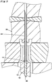
- Fig. 1 is a schematic cross-sectional front view of an embodiment of an injection molding die 1 of the present invention.
- the injection molding die 1 is configured to mold a needle-equipped syringe 60 including an injection needle 61 and a barrel 62 to which the injection needle 61 is fixed (see Fig. 4A ).
- the injection molding die 1 includes: a male die 10 including a core pin 13 that forms an internal surface of the barrel 62 of the needle-equipped syringe 60, a fixing plate 14 to which the pin proximal end of the core pin 13 is fitted, and a through hole 12 into which the injection needle 61 that is a metal cylindrical needle is inserted from the pin distal end of the core pin 13; a support rod 40 inserted from the pin proximal end of the core pin 13 into the through hole 12; a female die 20 including a concave part 24 that forms the external surface of the barrel 62 and communicates with the female die opening part 23b; and a resin injection gate 33 used to inject resin into the cavity space 20a formed of the male die 10 and the female die 20.
- the support rod 40 has contact with the needle proximal end of the injection needle 61 inserted in the through hole 12 and can push up the injection needle 61.
- Fig. 1 illustrates a state before the support rod 40 pushes up the injection needle 61.
- the core pin 13 of the male die 10 has a columnar shape and an even diameter between the pin distal end and pin proximal end of the core pin 13.
- the pin distal end is formed in a substantially conical shape.
- the top of the pin distal end includes a protrusion 11.
- the proximal end part of the core pin 13 has a cylindrical column shape with an expanded diameter.
- the incline of the substantially conical shape is steeper at the protrusion 11 than at the base of the substantially conical shape near the distal end of the core pin 13.
- the through hole 12 penetrates through the central axis of the core pin 13 from the pin distal end to pin proximal end.
- the inner diameter of the through hole 12 is slightly larger than the outer diameter of the injection needle 61 so that there is some play making it easy to insert the injection needle 61.
- the outer diameter of the protrusion 11 is equal to or smaller than 1.5 mm, and is preferably equal to or smaller than 1.0 mm, and more preferably equal to or smaller than 0.5 mm.
- the height of the protrusion 11 is equal to or lower than 1.5 mm, and is preferably equal to or lower than 1.0 mm, and more preferably equal to or lower than 0.5 mm. Note that the smaller protrusion 11 is more preferable.
- the protrusion 11 is not necessarily required.
- the through hole 12 is formed in a cylindrical shape and has the inner diameter slightly larger than the outer diameter of the injection needle 61.
- the difference between the inner diameter of the through hole 12 and the outer diameter of the injection needle 61 provides slight play large enough to insert and push up the injection needle 61. This play prevents the through hole 12 from scratching the surface of the inserted injection needle 61 and prevents the injection needle 61 from inclination.
- the fixing plate 14 includes a fitting hole into which the pin proximal end of the core pin 13 having a columnar shape and the expanded diameter is fitted.
- the core pin 13 is fitted into the fitting hole and vertically supported.
- the through hole 12 penetrates through the fixing plate 14 while coaxially extending from the fitting hole to bottom surface of the fixing plate 14 in the same diameter.
- the support rod 40 is inserted into the through hole 12 from the pin proximal end of the core pin 13 through the fixing plate 14.
- the distal end of the support rod 40 has contact with the injection needle 61. This contact causes the support rod 40 to support the injection needle 61 by poking and pushing up the injection needle 61. This prevents the injection needle 61 from dropping from the through hole 12.
- a distal end surface of the support rod 40 has a concave surface of which center is recessed so as to support the injection needle 61 in the minimum contact with the proximal end of the injection needle 61.
- the proximal end of the support rod 40 is stuck and fixed to the drive plate 50 that gradually pushes up the support rod 40.
- the drive plate 50 is connected to an up-and-down drive source (not illustrated). This connection enables the distal end surface of the support rod 40 to move up and down in the through hole 12 and adjust the vertical position of the injection needle 61 inserted in the through hole 12.
- the female die 20 includes: a body forming female die 23 mounted on the fixing plate 14 and configured to mold a body 65 and a flange 68 of the barrel 62; a nozzle part forming female die 22 mounted on the body forming female die 23 and configured to mold the proximal end of the nozzle part 63 of the barrel 62; and a needle holding female die 21 mounted on the nozzle part forming female die 22 and configured to mold a head 63a of the nozzle part 63 (see Fig. 4B ) and hold the injection needle 61 when the barrel 62 is molded.
- the body forming female die 23 includes: a body forming space 23a configured to form a cavity space 20a corresponding to the body 65 and the flange 68 of the barrel 62 (see Fig. 4A ) between the body forming female die 23 and the core pin 13 penetrating the body forming female die 23; and a female die opening part 23b from which the core pin 13 is inserted into the body forming space 23a.
- the female die opening part 23b and the body forming space 23a are arranged coaxially with the core pin 13.
- the nozzle part forming female die 22 is provided with a nozzle forming space 22c on the surface of the nozzle part forming female die 22 facing the body forming female die 23.
- the nozzle forming space 22c is a recessed part used to form a pleated skirt 63c of the nozzle part 63 of the barrel 62 (see Fig. 4B ).
- the nozzle forming space 22c is placed coaxially with the core pin 13.
- the nozzle part forming female die 22 includes a left die 22 L and a right die 22 R that can be separate into right and left in order to remove the head 63a and pleated skirt 63c of the nozzle part 63 formed in the head forming space 21e (see Fig. 4B ). Symmetrically putting the left die 22 L and right die 22 R together and merging the separate surfaces form the nozzle forming space 22c.
- the needle holding female die 21 includes on the surface facing the nozzle part forming female die 22 a head forming space 21e and an injection needle holding hole 21a.
- the head forming space 21e is used to form the head 63a of the nozzle part 63.
- the injection needle holding hole 21a holds the injection needle 61.
- the injection needle holding hole 21a and the through hole 12 are coaxially arranged.
- the peripheral edge of the head forming space 21e is larger than the nozzle forming space 22c.
- the center of the head forming space 21e is provided with a convex part 21c surrounding the opening part of the injection needle holding hole.
- a part of the convex part 21c that is an edge of the opening part of the injection needle holding hole is chamfered so that an inclined part 21d that slightly extends the opening part of the injection needle holding hole is formed. This smoothly introduces and inserts the injection needle 61 into the injection needle holding hole 21a even when the injection needle 61 is slightly inclined.
- the surface of the convex part 21c and the internal surface of the head forming space 21e are preferably pear-skin finished or roughened in order to facilitate the removal of the resin from the parts.
- the needle holding female die 21 is provided with a pair of clamping units 21b configured to clamp the injection needle 61.
- the pair of clamping units 21b detachably penetrates through the needle holding female die 21 in a direction perpendicular to the direction of the axis of the injection needle 61 so that the pair of clamping units 21b can clamp and fix the pushed-up injection needle 61 while the central axis of the injection needle 61 and the central axis of the core pin 13 are substantially aligned in the injection needle holding hole 21a.
- the nozzle part forming female die 22 is mounted on the body forming female die 23. Additionally, the needle holding female die 21 is mounted on the nozzle part forming female die 22. This forms the concave part 24 including the body forming space 23a, the nozzle forming space 22c, and the head forming space 21e.
- the concave part 24 corresponds to the external shape of the barrel 62 in order to form the external surface of the barrel 62.
- the core pin 13 is coaxially inserted into the concave part 24.
- the concave part 24, the core pin 13, and the fixing plate 14 form the cavity space 20a used to mold the barrel 62 when the body forming female die 23 has contact with the fixing plate 14.
- the core pin 13, the nozzle forming space 22c, and the injection needle holding hole 21a are coaxially arranged in the cavity space 20a.
- the cavity space 20a forms a space large enough to form the body 65 and nozzle part 63 of the barrel 62 and the flange 68 of the needle-equipped syringe 60 in predetermined thicknesses.
- the resin injection gate 33 is used to inject resin into the cavity space 20a.
- the resin injection gate 33 is located only on a side of the body forming female die 23 so as to form the side surface of an end of the flange 68.
- a resin injection nozzle 30 used to introduce and inject the thermally-melt thermoplastic resin into the cavity space 20a is connected to the resin injection gate 33.
- the resin injection nozzle 30 includes a tubular runner 31 through which the thermally-melt thermoplastic resin flows.
- the runner 31 communicates with the cavity space 20a forming the flange 68 so as to fill the cavity space 20a with the resin through the resin injection gate 33.
- a heater 32 that maintains a state in which the resin in the runner 31 is melt is provided around the runner 31.
- the female die 20 is coupled to an up-and-down drive source (not illustrated) that causes the dies 21, 22, and 23 to cooperate with each other or is coupled to a plurality of up-and-down drive sources (not illustrated) that cause the dies 21, 22, and 23 to separately operate, respectively, so that the body forming female die 23 comes into contact with the fixing plate 14, the nozzle part forming female die 22 comes into contact with the body forming female die 23, and the needle holding female die 21 comes into contact with the nozzle part forming female die 22 sequentially.
- the contacts form the female die 20 for injection molding.
- the drive plate 50 can be coupled to an up-and-down drive source (not illustrated) that causes the drive plate 50 to cooperate with the dies 21, 22, and 23 or to operate separately from the dies 21, 22, and 23 so that the drive plate 50 has contact with the fixing plate 14.
- the female die 20 is coupled to the up-and-down drive source (s) so that the dies of the female die 20 are divided in reverse order in order to remove the needle-equipped syringe 60 from the female die 20 after the injection molding.
- the distal end of the core pin 13 can substantially be formed in a hemispherical shape or a halved polyhedral shape.
- the external shape of the protrusion 11 can substantially be formed in a frustum of a cone, a hemispherical shape, or a frustum of a pyramid.
- the needle holding female die 21 and/or the body forming female die 23 can be a pair of dies that face each other and can open and close in a direction perpendicular to the direction of the axis of the core pin 13.
- any one of the needle holding female die 21, the nozzle part forming female die 22, the body forming female die 23, the drive plate 50, and the fixing plate 14 may be immovable or all of them may be movable as long as the needle holding female die 21, the nozzle part forming female die 22, the body forming female die 23, the drive plate 50, and the fixing plate 14 relatively operate similarly to the example.
- the injection molding die 1 is used to produce a needle-equipped syringe 60 as described below.
- the needle holding female die 21, the nozzle part forming female die 22, the body forming female die 23, the fixing plate 14, and the drive plate 50 are separate from each other. Meanwhile, the core pin 13 of the male die 10 is completely removed from the body forming space 23a of the body forming female die 23. Additionally, the support rod 40 is inserted in the through hole 12 of the core pin 13.
- the nozzle part forming female die 22 is formed of the left die 22 L and right die 22 R put together.
- the support rod 40 is gradually pushed up so that the injection needle 61 is inserted into the through hole 12 deeply enough to cause the tip of the injection needle 61 to protrude from the through hole 12.
- the needle proximal end of the injection needle 61 is inserted into the through hole 12, and the support rod 40 pushes up and supports the injection needle 61.
- the body forming female die 23 is placed at a position higher than the needle distal end of the injection needle 61 so that the body forming space 23a and the core pin 13 are coaxially arranged. While the central axis of the core pin 13 and the central axis of female die opening part 20 are aligned, the body forming female die 23 moves in a closing direction A 4 until the body forming female die 23 comes into contact with the fixing plate 14. This movement inserts the core pin 13 into the body forming space 23a.
- the nozzle part forming female die 22 is placed at a position higher than the needle distal end of the injection needle 61 so that the nozzle forming space 22c and the core pin 13 are coaxially arranged. While the central axes of the nozzle forming space 22c and the core pin 13 are aligned, the nozzle part forming female die 22 moves in a closing direction A 3 until the nozzle part forming female die 22 comes into contact with the body forming female die 23.
- the needle holding female die 21 is placed at a position higher than the needle distal end of the injection needle 61 so that the injection needle holding hole 21a and the core pin 13 are coaxially arranged. While the central axes of the injection needle holding hole 21a and the core pin 13 are aligned, the injection needle 61 is inserted into the injection needle holding hole 21a and the needle holding female die 21 moves in a closing direction A 2 until the needle holding female die 21 comes into contact with the nozzle part forming female die 22. The movement inserts the tip part of the injection needle 61 into the injection needle holding hole 21a. Meanwhile, the tip of the injection needle 61 is placed at a position lower than the clamping units 21b.
- the concave part 24 including the body forming space 23a, the nozzle forming space 22c, and the head forming space 21e is formed in the female die 20.
- the cavity space 20a is formed between the female die 20 and the male die 10.
- the injection needle 61 is deeply inserted in the core pin 13. This deep insertion prevents the injection needle 61 from being inclined when the cavity space 20a is formed.
- the drive plate 50 moves in a closing direction A 5 until the drive plate 50 comes into contact with the fixing plate 14.
- the support rod 40 connected to the drive plate 50 lunges upward and pushes up the needle proximal end of the injection needle 61 to the vicinity of the distal end of the protrusion 11.
- the needle proximal end of the injection needle 61 moves to a position higher than the clamping units 21b.
- the proximal end of the injection needle 61 is pushed up immediately under the distal end of the protrusion 11 highly enough to prevent the resin from flowing from the needle proximal end into the hole of the injection needle 61.
- the inj ection needle 61 is pushed up in the injection needle holding hole 21a and held in a state in which the central axis of the injection needle 61 is aligned with the central axis of the core pin 13. This can minimize the size of the protrusion 11 in the injection molding die 1 (see Fig. 3 ), and thus can extremely reduce the size of the recessed part 64 formed by the transfer of the protrusion 11 on the inner wall of the barrel 62 of the needle-equipped syringe 60.
- the recessed part 64 can be a dead space.
- the size of the recessed part 64 can be reduced approximately to a few percentages or a few tenths of that of a needle-equipped syringe that is molded with deeply insertion of the injection needle 61 into the core pin 13 to minimize inclination of the injection needle 61 as in the prior art (see Fig. 6 ).
- the clamping units 21b move in a closing direction A 1 .
- This movement can fix the injection needle 61 in a state in which the injection needle 61 is substantially arranged coaxially with the core pin 13.
- the melt resin is injected through the runner 31 from the resin injection gate 33 to the cavity space 20a for injection molding to mold the needle-equipped syringe 60.
- the cavity space 20a corresponding to the flange 68, body 65, nozzle part 63 of the needle-equipped syringe 60 is filled with the thermally-melt thermoplastic resin sequentially.
- the resin is continuously filled for a while, and the cavity space 20a is completely filled with the resin to a position corresponding to the head 63a of the nozzle part 63.
- the thermally-melt resin in the cavity space 20a is cooled and solidified. Meanwhile, the injection needle 61 is held at a predetermined position and the needle proximal end is slightly embedded in the protrusion 11.
- the core pin 13 placed in the cavity space 20a forms an internal hollow 66 of the barrel 62 to be filled with drug solution and an opening part 67 from which the drug solution is injected in the internal hollow 66.
- the concave part 24 of the cavity space 20a forms the outer wall of the barrel 62 (see Fig. 4A ).
- the clamping units 21b are moved and opened in a direction opposite to the closing direction A 1 so that the needle holding female die 21 is movable. Subsequently, the needle holding female die 21 is moved in a direction opposite to the closing direction A 2 . Furthermore, the nozzle part forming female die 22 is divided into the left die 22L and the right die 22 R , and moved in a direction opposite to the closing direction A 3 . After that, the body forming female die 23 is moved in a direction opposite to the closing direction A 4 so that the injection molding die 1 is opened. The molded needle-equipped syringe 60 is removed from the core pin 13. The burr formed on the flange 68 due to the resin injection gate 33 is removed as necessary.
- the needle-equipped syringe 60 of the present invention produced as described above is formed of the barrel 62 made of resin and the injection needle 61 integrated with the nozzle part 63 of the barrel 62 as illustrated in Fig. 4A .
- the barrel 62 is formed in a cylindrical shape and includes : the body 65 including the internal hollow 66 to be filled with drug solution, and formed of the nozzle part 63 located on the distal end of the barrel 62 and the peripheral wall continuously formed around the nozzle part 63 and extending toward the proximal end; and the opening part 67 located on the proximal end.
- the opening part 67 includes the flange 68 extending outward and vertically to the axis of the body 65.
- the flange 68 includes only a gate mark 69 on the external surface of the flange 68. The gate mark is left with the resin injection gate 33 when the needle-equipped syringe 60 is formed.
- the injection needle 61 penetrates through the nozzle part 63.
- the nozzle part 63 includes the recessed part 64 that is formed by the transfer of protrusion 11 and is formed substantially in a frustum of a cone on the internal surface of the nozzle part 63.
- the outer diameter of the recessed part 64 is equal to or smaller than 1.5 mm, and is preferably equal to or smaller than 1.0 mm, and more preferably equal to or smaller than 0.5 mm.
- the depth of the recessed part 64 is equal to or lower than 1.5 mm, and is preferably equal to or lower than 1.0 mm, and more preferably equal to or lower than 0.5 mm. Note that the smaller recessed part 64 is more preferable.
- the recessed part 64 is not necessarily required.
- the needle proximal end of the injection needle 61 slightly protrudes from the recessed part 64 to the internal hollow 66 of the body 65.
- the length of the needle proximal end protruding to the internal hollow 66 is equal to or shorter than 1.5 mm, and is preferably equal to or shorter than 1.0 mm, and more preferably equal to or shorter than 0.5 mm, and more preferably 0 mm. This can minimize the dead space formed between the proximal end of the injection needle 61 and the distal end (bottom) of the recessed part 64 corresponding to the distal end of the protrusion 11 in the recessed part 64. Even when the dead space is filled with the drug solution, the amount of the filled drug solution is extremely small. Thus, the filled drug solution is completely discharged. The complete discharge contributes to the efficient usage of the drug solution.
- the injection needle 61 is held in a state in which the part from the center to the tip of the distal end of the injection needle 61 protrudes from the nozzle part 63 toward a side on the distal end of the nozzle part 63.
- the axis of the held injection needle 61 is not inclined at all or is hardly inclined. This preferably makes the held injection needle 61 substantially parallel to the axis of the outer peripheral surface of the body 65.
- the substantial parallelism means that the axis of the injection needle 61 is absolutely parallel to the axis of the outer peripheral surface of the body 65 of the barrel 62, or that the central axis of the injection needle 61 is inclined at an angle of two degrees or less with respect to the central axis of the outer peripheral surface of the body 65.
- the nozzle part 63 includes the pleated skirt 63c and the head 63a.
- the circular head 63a of which diameter is expanded to some degree is mounted on the pleated skirt 63c, and includes a circular incline 63b that is the center of the circular recessed part of the head 63a bulging in a conical shape and penetrated by the injection needle 61.
- the recessed part 64 can substantially be formed in a frustumof a cone, a hemispherical shape, or a frustum of a pyramid, depending on the shape of the protrusion 11.
- the center of the head 63a can bulge in a domical shape around the injection needle 61, depending on the shape of the inclined part 21d.
- the pleated skirt 63c of the nozzle part 63 can have a polygonal prism shape such as quadrangular prisms or hexagonal prisms or a columnar shape that enables the nozzle part 63 to maintain the strength to hold the injection needle 61.
- the resin to form the barrel 62 is selected in terms, for example, of the chemical resistance, heat resistance, gas and/or bacteria barrier property, safety of a living body, and transparency.
- Thermoplastic resin for example, polyolefin resin such as polyethylene, polypropylene, and cyclo-olefin polymers; polystyrene; polycarbonate; or polyester such as polyethylene terephthalate; polyamide is used.
- cyclic olefin homopolymer or cyclic olefin copolymer is preferably used because such resins are transparent enough to visually confirm the contained drug solution from the outside and have a little interaction with the drug solution.
- the injection needle 61 is made of a material durable enough to be used for injection molding, and selected in terms, for example, of the chemical resistance, heat resistance, gas and/or bacteria barrier property, and safety of a living body.
- a material durable enough to be used for injection molding and selected in terms, for example, of the chemical resistance, heat resistance, gas and/or bacteria barrier property, and safety of a living body.
- stainless steel and nickel-free stainless steel can be cited as the material.
- Stainless steel relatively easy to form and inexpensive is preferable.
- the position where the nozzle part 63 holds the needle proximal end of the injection needle 61 is not necessarily the center of the nozzle part 63.
- the position can be moved from the center in a radial direction of the body 65 to some degree.
- the injection needle 61 can be inserted into the through hole 12 after the bevel of the injection needle 61 is detected with a sensor and the orientation of the injection needle 61 is adjusted so that the bevel faces the flange 68.
- Fig. 5 is a schematic cross-sectional front view of another embodiment of the injection molding die 1.
- the injection molding die 1 includes a core pin 13 including a cooling mechanism in the core pin 13 instead of the core pin 13 illustrated in Fig. 1 .
- the cooling mechanism cools the thermally-melt thermoplastic resin injected from the resin injection gate 33 by heat conduction, and is, for example, a water cooling mechanism in which cooling water flows for heat exchange.
- the cooling mechanism includes a groove through which cooling water flows in the core pin 13.
- the inside of the core pin 13 is cylindrically hollowed and a cylindrical core 15 is fitted and screwed to the hollowed inside.
- the core pin 13 is provided with the throughhole 12 penetrating the central axis of the core pin 13 including the core 15 from the needle distal end to needle proximal end of the core pin 13.
- the core 15 is provided with a pair of longitudinal grooves 15b on the side surfaces of the core rod 15c symmetrically with respect to the core rod 15c from the lower end to upper end of the core rod 15c.
- the core 15 is provided with a lateral groove 15a formed in a semi-circle and connecting the upper ends of the longitudinal grooves 15b.
- the lower ends of the longitudinal grooves 15b are connected to a pipe 14a provided in the fixing plate 14 so that the cooling water flows from one longitudinal groove 15b through the lateral groove 15a to another longitudinal groove 15b.
- the cooling water flowing in the lateral groove 15a and the longitudinal grooves 15b flows in the flow path in the core pin 13 so as to cool and solidify the thermally-melt resin injected in the cavity space 20a in the injection molding die 1.
- the cooling mechanism can be a thermal conductive metal rod cooled by a cooling medium.
- a method for producing a needle-equipped syringe using the injection molding die of the present invention can be used to produce a needle-equipped syringe in which there is a small dead space and the injection needle is not inclined with respect to the barrel.
- the needle-equipped syringe can be used for hypodermic injection, for example, of a biological product such as a vaccine.
Landscapes
- Health & Medical Sciences (AREA)
- Engineering & Computer Science (AREA)
- Hematology (AREA)
- Life Sciences & Earth Sciences (AREA)
- Vascular Medicine (AREA)
- Anesthesiology (AREA)
- Biomedical Technology (AREA)
- Heart & Thoracic Surgery (AREA)
- Veterinary Medicine (AREA)
- Public Health (AREA)
- Animal Behavior & Ethology (AREA)
- General Health & Medical Sciences (AREA)
- Mechanical Engineering (AREA)
- Manufacturing & Machinery (AREA)
- Infusion, Injection, And Reservoir Apparatuses (AREA)
- Moulds For Moulding Plastics Or The Like (AREA)
- Injection Moulding Of Plastics Or The Like (AREA)
Abstract
Description
- The present invention relates to an injection molding die used to mold a needle-equipped syringe used to inject a small amount of drug solution under the skin, and a method for producing the needle-equipped syringe using the injection molding die.
- The needle-equipped syringe is a syringe in which a thin injection needle penetrates through the distal end of a barrel to be used as the syringe barrel and then is fixed to the barrel. A gasket is attached to the distal end of a plunger and the plunger is inserted in the barrel. This enables the needle-equipped syringe to rapidly discharge a small amount of drug solution in the barrel from the injection needle by strongly pressing the drug solution with the plunger. Thus, the needle-equipped syringe is used for hypodermic injection rather than intravenous injection. The needle-equipped syringe includes the barrel to which the injection needle is fixed. Accordingly, the needle-equipped syringe does not require a complicated operation for attaching a separate injection needle hub immediately before the administration, and allows for easy and efficient administration of the drug solution. Thus, the needle-equipped syringe is used for general purposes.
- The needle-equipped syringe is produced with a manner in which a barrel including an insertion hole opening on the distal end of the barrel is produced, and an injection needle is inserted into and adhered to the insertion hole with adhesive. For pain relief at the administration, a low dosage, for example, about 500 µL of a biological product such as a vaccine is administrated by hypodermic injection. The injection needle adhered to the needle-equipped syringe has a small diameter. This often raises the pressure on the plunger too high when a small amount of drug solution is administrated. This may cause the injection needle to disconnect from the distal end of the barrel.
- In light of the foregoing, a needle-equipped syringe to which an injection needle is fixed instead of adhesion has been used recently. For example, as described in
Patent Literature 1, a needle-equipped syringe in which a barrel and an injection needle located on the distal end of the barrel are integrally formed is produced by injection molding in which resin is injected into an injection molding die on which the injection needle is provided. The needle-equipped syringe produced as describe above includes the injection needle directly and firmly fixed to the nozzle part of the barrel. Accordingly, the injection needle does not disconnect from the distal end of the barrel even when a high pressure is applied. Thus, the needle-equipped syringe is extremely safe. - A conventional injection molding die used to produce the needle-equipped syringe in injection molding includes: a
male die 10 provided with aprotrusion 11 that supports theinjection needle 61 so that theinjection needle 61 is deeply stuck to the distal end of thecore pin 13 and stands independently; and afemale die 20 that forms the external surface of the barrel, as illustrated inFig. 6 . A shallow insertion of theinjection needle 61 into theprotrusion 11 may cause an inclination of theinjection needle 61 in the middle of the formation of thecavity space 20a. This may causes the inclination of the central axis of theinjection needle 61 of the needle-equipped syringe molded by the injection of resin after the formation with respect to the central axis of the barrel. In light of the foregoing, theprotrusion 11 has a height and a thickness to some degree so that theinjection needle 61 can deeply be inserted in theprotrusion 11. As a result, the transferredprotrusion 11 is transferred and a deep and wide recessed part that is formed on the inner wall of the distal end of the molded barrel. The injection needle is fixed so that the proximal end of the needle is embedded in the recessed part. The recessed part is left as a dead space. The drug solution with which the recessed part is filled reaches no less than tens to a hundred and several tens µL. When the plunger presses the gasket, the distal end of the gasket comes into contact with the inner wall of the distal end of the barrel. This stops the plunger from pressing the gasket any more. Thus, the drug solution with which the recessed part is filled is not push out. The drug solution remains in the recessed part without discharge, and goes to waste. - In light of the foregoing, in order to efficiently use a limited batch of drug solution such as seasonal flu vaccine, there is a need for producing needle-equipped syringes with a minimum dead space so that the needle-equipped syringes can be produced as many as possible.
-
- Patent Literature 1:
-
JP 2013-70892 A - To solve the problem described above, an objective of the present invention is to provide: an injection molding die that can fix the injection needle to the barrel without inclining the injection needle and can produce a needle-equipped syringe with a minimum dead space hindering the discharge of the filled drug solution; a method for easily producing needle-equipped syringes as many as possible at a high yield using the injection molding die; and a needle-equipped syringe that is produced by the method and that enables nearly complete discharge of the filled drug solution.
- An injection molding die for molding a needle-equipped syringe that includes a barrel and an injection needle, the barrel including a cylindrical body, a nozzle part located on a distal end of the body, and an opening part located on a proximal end of the body, the barrel being made of resin, the injection needle including a needle distal end and a needle proximal end, the needle proximal end being held by the nozzle part, the barrel being integrally molded with the injection needle, the injection molding die comprising: a male die including: a core pin, and a through hole, wherein the core pin includes a pin distal end and a pin proximal end, and is configured to form an internal surface of the barrel, wherein the through hole penetrates through the core pin from the pin distal end to the pin proximal end and is configured such that the needle proximal end of the injection needle is insertable from the pin distal end into the through hole; a female die including: a female die opening part, a concave part, and an injection needle holding hole, wherein the concave part communicates with the female die opening part, is configured to form an external surface of the barrel,
wherein the injection needle holding hole is located on a side opposite to the female die opening part and coaxially with the through hole, wherein the injection needle holding hole communicates with the concave part, and is configured to hold the injection needle; a support rod that is insertable from the pin proximal end into the through hole, wherein the support rod is configured to push up and support the needle proximal end of the injection needle inserted from the pin distal end, and to push up the needle proximal end to a vicinity of the pin distal end; and a resin injection gate configured to allow the resin to be injected to a cavity space formed by the concave part and the core pin inserted from the female die opening part. - In the injection molding die, it is preferable that a rising amount of the support rod is adjustable such that a distance between a distal end of the support rod and the pin distal end is 1.5 mm or less.
- In the injection molding die, it is preferable that the core pin includes a protrusion on the pin distal end, the protrusion being configured to prevent the resin from entering the injection needle by surrounding the needle proximal end.
- In the injection molding die, it is preferable that an outer diameter of the protrusion is 1.5 mm or less, and a height of the protrusion is 1.5 mm or less.
- In the injection molding die, it is preferable that the male die includes a cooling mechanism in the core pin, and the cooling mechanism is configured to cool the resin injected from the resin injection gate by thermal conduction.
- In the injection molding die, it is preferable that the female die includes clamping units configured to clamp the injection needle in the injection needle holding hole.
- A method for producing a needle-equipped syringe using an injection molding die, the needle-equipped syringe including a barrel and an injection needle, the barrel including a cylindrical body, a nozzle part located on a distal end of the body, and an opening part located on a proximal end of the body, the barrel being made of resin, the injection needle including a needle distal end and a needle proximal end, the needle proximal end being held by the nozzle part, the method comprising: providing a male die including: a core pin, and a through hole, wherein the core pin includes a pin distal end and a pin proximal end, and is configured to form an internal surface of the barrel, wherein the through hole penetrates through the core pin from the pin distal end to the pin proximal end, providing a female die including: a female die opening part, a concave part, and an injection needle holding hole, wherein the concave part communicates with the female die opening part, and is configured to form an external surface of the barrel, wherein the injection needle holding hole is located on a side opposite to the female die opening part and coaxially with the through hole, wherein the injection needle holding hole communicates with the concave part, providing a support rod that is inserted from the pin proximal end into the through hole; inserting the injection needle from the needle proximal end into the through hole from the pin distal end, and pushing up and supporting the needle proximal end of the injection needle with the support rod; forming a cavity space formed of the concave part and the core pin by inserting the core pin from the female die opening part into an internal hollow of the concave part; pushing up the needle proximal end to a vicinity of the pin distal end by gradually pushing up the support rod inserted in the through hole, and holding the injection needle in the injection needle holding hole; and integrally forming the injection needle and the barrel by injecting the resin in the cavity space.
- In the method for producing a needle-equipped syringe, it is preferable that the support rod is gradually pushed up until a distance between the distal end of the support rod and the pin distal end is 1.5 mm or less.
- In the method for producing a needle-equipped syringe, it is preferable that a protrusion is formed on the pin distal end, the protrusion being configured to prevent the resin from entering the through hole by surrounding the needle proximal end, and wherein when the resin is injectedinto the cavity space, a recessed part corresponding to the protrusion is formed in the barrel, and the needle proximal end is embedded in the recessed part.
- In the method for producing a needle-equipped syringe, it is preferable that the protrusion is formed such that an outer diameter of the protrusion is 1.5 mm or less, and a height of the protrusion is 1.5 mm or less.
- In the method for producing a needle-equipped syringe, it is preferable that clamping units configured to clamp the injection needle in the injection needle holding hole are located in the female die, and wherein after pushing up the injection needle by a gradual push-up of the support rod, the injection needle, while supported by the support rod, is clamped by the clamping units.
- In the method for producing a needle-equipped syringe, it is preferable that a cooling mechanism configured to cool the resin injected from the resin injection gate by thermal conduction is provided in the core pin, and the method further comprises cooling and solidifying the resin injected in the cavity with the cooling mechanism such that the injection needle and the barrel are integrally formed, and removing the integrally-formed injection needle and barrel.
- A needle-equipped syringe comprising: a barrel including: a cylindrical body, a nozzle part located on a distal end of the body, and an opening part located on a proximal end of the body, wherein the barrel is made of resin; and an injection needle held by the nozzle part, wherein the barrel is integrally molded with the injection needle, and the body is configured to be filled with drug solution, wherein a recessedpart is located on a proximal end of the nozzle part, the recessed part being surrounded by an inner wall of the barrel and recessed distally, wherein an outer diameter of the recessed part is 1.5 mm or less, and a height of the recessed part is 1.5 mm or less, and
wherein a needle proximal end of the injection needle protrudes in the recessed part by 1.5 mm or less. - The injection molding die according to the present invention is configured to mold a needle-equipped syringe in a manner in which a through hole penetrates through a core pin from the pin distal end to the pin proximal end of the core pin, a support rod is inserted from the pin proximal end in the through hole, and the support rod supports the injection needle inserted from the pin distal end and pushes up the injection needle when resin is injected. Using the injection molding die allows the injection needle to deeply be inserted into the through hole and be supported by the support rod when the male die and the female die form a cavity space, and thus prevents the injection needle frominclination. Thus, the injection needle can be fixed to the barrel without inclination. This can form a needle-equipped syringe with a small dead space.
- According to the method for producing a needle-equipped syringe of the present invention, the injection needle is deeply inserted into the through hole of the injection molding die, and the support rod pushes up the injection needle as high as possible while supporting the injection needle in order to prevent the injection needle from inclination. This can efficiently and easily mold a needle-equipped syringe with a small dead space at a high yield.
- In the needle-equipped syringe according to the present invention, the needle proximal end of the injection needle hardly protrudes in the internal hollow of the barrel, and thus the recessed part of the inner wall of the nozzle part surrounding the protrusion is extremely small. This reduces the dead space. The reduced dead space allows for nearly complete discharge of the filled drug solution. Additionally, the rate of defective products in which the central axis of the injection needle and the central axis of the body of the barrel are misaligned is low among the needle-equipped syringes. The needle-equipped syringes can be produced at a high yield. The needle-equipped syringes are highly safe and reliable.
-
-
Fig. 1 is a schematic cross-sectional front view of a state before an injection needle is pushed up while an injection molding die of the present invention is used. -
Fig. 2 is a schematic cross-sectional front view of a state in which the injection needle is pushed up and resin is injected while the injection molding die of the present invention is used. -
Fig. 3 is an enlarged partial cross-sectional front view of the main parts of the injection molding die of the present invention. -
Fig. 4A is a perspective view of a needle-equipped syringe of the present invention. -
Fig. 4B is an enlarged cross-sectional view of a part of the needle-equipped syringe of the present invention. -
Fig. 5 is a schematic cross-sectional front view of another embodiment of the injection molding die of the present invention. -
Fig. 6 is an enlarged partial cross-sectional front view of the main parts of the injection molding die to which the present invention is not applied. - Hereinafter, the embodiments of the present invention will be described in detail. However, the scope of the present invention is not limited to the embodiments.
-
Fig. 1 is a schematic cross-sectional front view of an embodiment of an injection molding die 1 of the present invention. The injection molding die 1 is configured to mold a needle-equippedsyringe 60 including aninjection needle 61 and abarrel 62 to which theinjection needle 61 is fixed (seeFig. 4A ). The injection molding die 1 includes: amale die 10 including acore pin 13 that forms an internal surface of thebarrel 62 of the needle-equippedsyringe 60, a fixingplate 14 to which the pin proximal end of thecore pin 13 is fitted, and a throughhole 12 into which theinjection needle 61 that is a metal cylindrical needle is inserted from the pin distal end of thecore pin 13; asupport rod 40 inserted from the pin proximal end of thecore pin 13 into the throughhole 12; afemale die 20 including aconcave part 24 that forms the external surface of thebarrel 62 and communicates with the femaledie opening part 23b; and aresin injection gate 33 used to inject resin into thecavity space 20a formed of the male die 10 and thefemale die 20. Thesupport rod 40 has contact with the needle proximal end of theinjection needle 61 inserted in the throughhole 12 and can push up theinjection needle 61.Fig. 1 illustrates a state before thesupport rod 40 pushes up theinjection needle 61. - The
core pin 13 of the male die 10 has a columnar shape and an even diameter between the pin distal end and pin proximal end of thecore pin 13. The pin distal end is formed in a substantially conical shape. The top of the pin distal end includes aprotrusion 11. The proximal end part of thecore pin 13 has a cylindrical column shape with an expanded diameter. The incline of the substantially conical shape is steeper at theprotrusion 11 than at the base of the substantially conical shape near the distal end of thecore pin 13. The throughhole 12 penetrates through the central axis of thecore pin 13 from the pin distal end to pin proximal end. The inner diameter of the throughhole 12 is slightly larger than the outer diameter of theinjection needle 61 so that there is some play making it easy to insert theinjection needle 61. - The outer diameter of the
protrusion 11 is equal to or smaller than 1.5 mm, and is preferably equal to or smaller than 1.0 mm, and more preferably equal to or smaller than 0.5 mm. The height of theprotrusion 11 is equal to or lower than 1.5 mm, and is preferably equal to or lower than 1.0 mm, and more preferably equal to or lower than 0.5 mm. Note that thesmaller protrusion 11 is more preferable. Theprotrusion 11 is not necessarily required. - The through
hole 12 is formed in a cylindrical shape and has the inner diameter slightly larger than the outer diameter of theinjection needle 61. The difference between the inner diameter of the throughhole 12 and the outer diameter of theinjection needle 61 provides slight play large enough to insert and push up theinjection needle 61. This play prevents the throughhole 12 from scratching the surface of the insertedinjection needle 61 and prevents theinjection needle 61 from inclination. - The fixing
plate 14 includes a fitting hole into which the pin proximal end of thecore pin 13 having a columnar shape and the expanded diameter is fitted. Thecore pin 13 is fitted into the fitting hole and vertically supported. The throughhole 12 penetrates through the fixingplate 14 while coaxially extending from the fitting hole to bottom surface of the fixingplate 14 in the same diameter. - The
support rod 40 is inserted into the throughhole 12 from the pin proximal end of thecore pin 13 through the fixingplate 14. The distal end of thesupport rod 40 has contact with theinjection needle 61. This contact causes thesupport rod 40 to support theinjection needle 61 by poking and pushing up theinjection needle 61. This prevents theinjection needle 61 from dropping from the throughhole 12. A distal end surface of thesupport rod 40 has a concave surface of which center is recessed so as to support theinjection needle 61 in the minimum contact with the proximal end of theinjection needle 61. - The proximal end of the
support rod 40 is stuck and fixed to thedrive plate 50 that gradually pushes up thesupport rod 40. Thedrive plate 50 is connected to an up-and-down drive source (not illustrated). This connection enables the distal end surface of thesupport rod 40 to move up and down in the throughhole 12 and adjust the vertical position of theinjection needle 61 inserted in the throughhole 12. - The female die 20 includes: a body forming female die 23 mounted on the fixing
plate 14 and configured to mold abody 65 and aflange 68 of thebarrel 62; a nozzle part forming female die 22 mounted on the body formingfemale die 23 and configured to mold the proximal end of thenozzle part 63 of thebarrel 62; and a needle holding female die 21 mounted on the nozzle part formingfemale die 22 and configured to mold ahead 63a of the nozzle part 63 (seeFig. 4B ) and hold theinjection needle 61 when thebarrel 62 is molded. - The body forming
female die 23 includes: abody forming space 23a configured to form acavity space 20a corresponding to thebody 65 and theflange 68 of the barrel 62 (seeFig. 4A ) between the body formingfemale die 23 and thecore pin 13 penetrating the body formingfemale die 23; and a femaledie opening part 23b from which thecore pin 13 is inserted into thebody forming space 23a. The femaledie opening part 23b and thebody forming space 23a are arranged coaxially with thecore pin 13. - The nozzle part forming
female die 22 is provided with anozzle forming space 22c on the surface of the nozzle part forming female die 22 facing the body formingfemale die 23. Thenozzle forming space 22c is a recessed part used to form apleated skirt 63c of thenozzle part 63 of the barrel 62 (seeFig. 4B ). Thenozzle forming space 22c is placed coaxially with thecore pin 13. - Note that the nozzle part forming
female die 22 includes aleft die 22L and aright die 22R that can be separate into right and left in order to remove thehead 63a andpleated skirt 63c of thenozzle part 63 formed in thehead forming space 21e (seeFig. 4B ). Symmetrically putting the left die 22L and right die 22R together and merging the separate surfaces form thenozzle forming space 22c. - The needle holding
female die 21 includes on the surface facing the nozzle part forming female die 22 ahead forming space 21e and an injectionneedle holding hole 21a. Thehead forming space 21e is used to form thehead 63a of thenozzle part 63. The injectionneedle holding hole 21a holds theinjection needle 61. The injectionneedle holding hole 21a and the throughhole 12 are coaxially arranged. - The peripheral edge of the
head forming space 21e is larger than thenozzle forming space 22c. The center of thehead forming space 21e is provided with aconvex part 21c surrounding the opening part of the injection needle holding hole. A part of theconvex part 21c that is an edge of the opening part of the injection needle holding hole is chamfered so that aninclined part 21d that slightly extends the opening part of the injection needle holding hole is formed. This smoothly introduces and inserts theinjection needle 61 into the injectionneedle holding hole 21a even when theinjection needle 61 is slightly inclined. - The surface of the
convex part 21c and the internal surface of thehead forming space 21e are preferably pear-skin finished or roughened in order to facilitate the removal of the resin from the parts. - Furthermore, the needle holding
female die 21 is provided with a pair of clampingunits 21b configured to clamp theinjection needle 61. The pair of clampingunits 21b detachably penetrates through the needle holdingfemale die 21 in a direction perpendicular to the direction of the axis of theinjection needle 61 so that the pair of clampingunits 21b can clamp and fix the pushed-upinjection needle 61 while the central axis of theinjection needle 61 and the central axis of thecore pin 13 are substantially aligned in the injectionneedle holding hole 21a. - The nozzle part forming
female die 22 is mounted on the body formingfemale die 23. Additionally, the needle holdingfemale die 21 is mounted on the nozzle part formingfemale die 22. This forms theconcave part 24 including thebody forming space 23a, thenozzle forming space 22c, and thehead forming space 21e. Theconcave part 24 corresponds to the external shape of thebarrel 62 in order to form the external surface of thebarrel 62. - The
core pin 13 is coaxially inserted into theconcave part 24. Theconcave part 24, thecore pin 13, and the fixingplate 14 form thecavity space 20a used to mold thebarrel 62 when the body formingfemale die 23 has contact with the fixingplate 14. Thecore pin 13, thenozzle forming space 22c, and the injectionneedle holding hole 21a are coaxially arranged in thecavity space 20a. Thecavity space 20a forms a space large enough to form thebody 65 andnozzle part 63 of thebarrel 62 and theflange 68 of the needle-equippedsyringe 60 in predetermined thicknesses. - The
resin injection gate 33 is used to inject resin into thecavity space 20a. Theresin injection gate 33 is located only on a side of the body forming female die 23 so as to form the side surface of an end of theflange 68. Aresin injection nozzle 30 used to introduce and inject the thermally-melt thermoplastic resin into thecavity space 20a is connected to theresin injection gate 33. Theresin injection nozzle 30 includes atubular runner 31 through which the thermally-melt thermoplastic resin flows. Therunner 31 communicates with thecavity space 20a forming theflange 68 so as to fill thecavity space 20a with the resin through theresin injection gate 33. Aheater 32 that maintains a state in which the resin in therunner 31 is melt is provided around therunner 31. - The female die 20 is coupled to an up-and-down drive source (not illustrated) that causes the dies 21, 22, and 23 to cooperate with each other or is coupled to a plurality of up-and-down drive sources (not illustrated) that cause the dies 21, 22, and 23 to separately operate, respectively, so that the body forming
female die 23 comes into contact with the fixingplate 14, the nozzle part formingfemale die 22 comes into contact with the body formingfemale die 23, and the needle holdingfemale die 21 comes into contact with the nozzle part forming female die 22 sequentially. The contacts form the female die 20 for injection molding. Finally, thedrive plate 50 can be coupled to an up-and-down drive source (not illustrated) that causes thedrive plate 50 to cooperate with the dies 21, 22, and 23 or to operate separately from the dies 21, 22, and 23 so that thedrive plate 50 has contact with the fixingplate 14. The female die 20 is coupled to the up-and-down drive source (s) so that the dies of the female die 20 are divided in reverse order in order to remove the needle-equippedsyringe 60 from the female die 20 after the injection molding. - The distal end of the
core pin 13 can substantially be formed in a hemispherical shape or a halved polyhedral shape. The external shape of theprotrusion 11 can substantially be formed in a frustum of a cone, a hemispherical shape, or a frustum of a pyramid. - The needle holding
female die 21 and/or the body forming female die 23 can be a pair of dies that face each other and can open and close in a direction perpendicular to the direction of the axis of thecore pin 13. - An example in which the needle holding
female die 21, the nozzle part formingfemale die 22, the body formingfemale die 23, and thedrive plate 50 are driven based on theimmovable fixing plate 14 has been described. Any one of the needle holdingfemale die 21, the nozzle part formingfemale die 22, the body formingfemale die 23, thedrive plate 50, and the fixingplate 14 may be immovable or all of them may be movable as long as the needle holdingfemale die 21, the nozzle part formingfemale die 22, the body formingfemale die 23, thedrive plate 50, and the fixingplate 14 relatively operate similarly to the example. - The injection molding die 1 is used to produce a needle-equipped
syringe 60 as described below. - First, the needle holding
female die 21, the nozzle part formingfemale die 22, the body formingfemale die 23, the fixingplate 14, and thedrive plate 50 are separate from each other. Meanwhile, thecore pin 13 of the male die 10 is completely removed from thebody forming space 23a of the body formingfemale die 23. Additionally, thesupport rod 40 is inserted in the throughhole 12 of thecore pin 13. The nozzle part formingfemale die 22 is formed of the left die 22L and right die 22R put together. - First, the
support rod 40 is gradually pushed up so that theinjection needle 61 is inserted into the throughhole 12 deeply enough to cause the tip of theinjection needle 61 to protrude from the throughhole 12. The needle proximal end of theinjection needle 61 is inserted into the throughhole 12, and thesupport rod 40 pushes up and supports theinjection needle 61. The body formingfemale die 23 is placed at a position higher than the needle distal end of theinjection needle 61 so that thebody forming space 23a and thecore pin 13 are coaxially arranged. While the central axis of thecore pin 13 and the central axis of femaledie opening part 20 are aligned, the body forming female die 23 moves in a closing direction A4 until the body formingfemale die 23 comes into contact with the fixingplate 14. This movement inserts thecore pin 13 into thebody forming space 23a. - Next, the nozzle part forming
female die 22 is placed at a position higher than the needle distal end of theinjection needle 61 so that thenozzle forming space 22c and thecore pin 13 are coaxially arranged. While the central axes of thenozzle forming space 22c and thecore pin 13 are aligned, the nozzle part forming female die 22 moves in a closing direction A3 until the nozzle part formingfemale die 22 comes into contact with the body formingfemale die 23. - Furthermore, the needle holding
female die 21 is placed at a position higher than the needle distal end of theinjection needle 61 so that the injectionneedle holding hole 21a and thecore pin 13 are coaxially arranged. While the central axes of the injectionneedle holding hole 21a and thecore pin 13 are aligned, theinjection needle 61 is inserted into the injectionneedle holding hole 21a and the needle holding female die 21 moves in a closing direction A2 until the needle holdingfemale die 21 comes into contact with the nozzle part formingfemale die 22. The movement inserts the tip part of theinjection needle 61 into the injectionneedle holding hole 21a. Meanwhile, the tip of theinjection needle 61 is placed at a position lower than the clampingunits 21b. - Then, the
concave part 24 including thebody forming space 23a, thenozzle forming space 22c, and thehead forming space 21e is formed in thefemale die 20. Thecavity space 20a is formed between thefemale die 20 and themale die 10. Theinjection needle 61 is deeply inserted in thecore pin 13. This deep insertion prevents theinjection needle 61 from being inclined when thecavity space 20a is formed. - Next, as illustrated in
Figs. 1 and2 , while the injectionneedle holding hole 21a, thenozzle forming space 22c, thebody forming space 23a, thehead forming space 21e, and thecore pin 13 are coaxially held, thedrive plate 50 moves in a closing direction A5 until thedrive plate 50 comes into contact with the fixingplate 14. In response to the movement, thesupport rod 40 connected to thedrive plate 50 lunges upward and pushes up the needle proximal end of theinjection needle 61 to the vicinity of the distal end of theprotrusion 11. The needle proximal end of theinjection needle 61 moves to a position higher than the clampingunits 21b. Meanwhile, the proximal end of theinjection needle 61 is pushed up immediately under the distal end of theprotrusion 11 highly enough to prevent the resin from flowing from the needle proximal end into the hole of theinjection needle 61. The inj ectionneedle 61 is pushed up in the injectionneedle holding hole 21a and held in a state in which the central axis of theinjection needle 61 is aligned with the central axis of thecore pin 13. This can minimize the size of theprotrusion 11 in the injection molding die 1 (seeFig. 3 ), and thus can extremely reduce the size of the recessedpart 64 formed by the transfer of theprotrusion 11 on the inner wall of thebarrel 62 of the needle-equippedsyringe 60. Thus, the recessedpart 64 can be a dead space. However, the size of the recessedpart 64 can be reduced approximately to a few percentages or a few tenths of that of a needle-equipped syringe that is molded with deeply insertion of theinjection needle 61 into thecore pin 13 to minimize inclination of theinjection needle 61 as in the prior art (seeFig. 6 ). - After that, the clamping
units 21b move in a closing direction A1. This movement can fix theinjection needle 61 in a state in which theinjection needle 61 is substantially arranged coaxially with thecore pin 13. After the injection molding die 1 is clamped, the melt resin is injected through therunner 31 from theresin injection gate 33 to thecavity space 20a for injection molding to mold the needle-equippedsyringe 60. - During the injection molding, the
cavity space 20a corresponding to theflange 68,body 65,nozzle part 63 of the needle-equippedsyringe 60 is filled with the thermally-melt thermoplastic resin sequentially. The resin is continuously filled for a while, and thecavity space 20a is completely filled with the resin to a position corresponding to thehead 63a of thenozzle part 63. The thermally-melt resin in thecavity space 20a is cooled and solidified. Meanwhile, theinjection needle 61 is held at a predetermined position and the needle proximal end is slightly embedded in theprotrusion 11. This prevents the resin from entering the needle hole from the proximal end, and solidifies the resin so that the resin surrounds substantially half of theinjection needle 61 in thenozzle forming space 22c. As a result, theinjection needle 61 is firmly fixed to and held on thebarrel 62 without blocking the needle hole. Meanwhile, thecore pin 13 placed in thecavity space 20a forms an internal hollow 66 of thebarrel 62 to be filled with drug solution and anopening part 67 from which the drug solution is injected in the internal hollow 66. Theconcave part 24 of thecavity space 20a forms the outer wall of the barrel 62 (seeFig. 4A ). - After that, when the resin is solidified, the clamping
units 21b are moved and opened in a direction opposite to the closing direction A1 so that the needle holdingfemale die 21 is movable. Subsequently, the needle holdingfemale die 21 is moved in a direction opposite to the closing direction A2. Furthermore, the nozzle part formingfemale die 22 is divided into the left die 22L and the right die 22R, and moved in a direction opposite to the closing direction A3. After that, the body formingfemale die 23 is moved in a direction opposite to the closing direction A4 so that the injection molding die 1 is opened. The molded needle-equippedsyringe 60 is removed from thecore pin 13. The burr formed on theflange 68 due to theresin injection gate 33 is removed as necessary. - The needle-equipped
syringe 60 of the present invention produced as described above is formed of thebarrel 62 made of resin and theinjection needle 61 integrated with thenozzle part 63 of thebarrel 62 as illustrated inFig. 4A . - The
barrel 62 is formed in a cylindrical shape and includes : thebody 65 including the internal hollow 66 to be filled with drug solution, and formed of thenozzle part 63 located on the distal end of thebarrel 62 and the peripheral wall continuously formed around thenozzle part 63 and extending toward the proximal end; and theopening part 67 located on the proximal end. The openingpart 67 includes theflange 68 extending outward and vertically to the axis of thebody 65. Theflange 68 includes only agate mark 69 on the external surface of theflange 68. The gate mark is left with theresin injection gate 33 when the needle-equippedsyringe 60 is formed. - The
injection needle 61 penetrates through thenozzle part 63. Thenozzle part 63 includes the recessedpart 64 that is formed by the transfer ofprotrusion 11 and is formed substantially in a frustum of a cone on the internal surface of thenozzle part 63. - The outer diameter of the recessed
part 64 is equal to or smaller than 1.5 mm, and is preferably equal to or smaller than 1.0 mm, and more preferably equal to or smaller than 0.5 mm. The depth of the recessedpart 64 is equal to or lower than 1.5 mm, and is preferably equal to or lower than 1.0 mm, and more preferably equal to or lower than 0.5 mm. Note that the smaller recessedpart 64 is more preferable. The recessedpart 64 is not necessarily required. - The needle proximal end of the
injection needle 61 slightly protrudes from the recessedpart 64 to the internal hollow 66 of thebody 65. The length of the needle proximal end protruding to the internal hollow 66 is equal to or shorter than 1.5 mm, and is preferably equal to or shorter than 1.0 mm, and more preferably equal to or shorter than 0.5 mm, and more preferably 0 mm. This can minimize the dead space formed between the proximal end of theinjection needle 61 and the distal end (bottom) of the recessedpart 64 corresponding to the distal end of theprotrusion 11 in the recessedpart 64. Even when the dead space is filled with the drug solution, the amount of the filled drug solution is extremely small. Thus, the filled drug solution is completely discharged. The complete discharge contributes to the efficient usage of the drug solution. - The
injection needle 61 is held in a state in which the part from the center to the tip of the distal end of theinjection needle 61 protrudes from thenozzle part 63 toward a side on the distal end of thenozzle part 63. - The axis of the held
injection needle 61 is not inclined at all or is hardly inclined. This preferably makes the heldinjection needle 61 substantially parallel to the axis of the outer peripheral surface of thebody 65. The substantial parallelism means that the axis of theinjection needle 61 is absolutely parallel to the axis of the outer peripheral surface of thebody 65 of thebarrel 62, or that the central axis of theinjection needle 61 is inclined at an angle of two degrees or less with respect to the central axis of the outer peripheral surface of thebody 65. - The
nozzle part 63 includes thepleated skirt 63c and thehead 63a. Thecircular head 63a of which diameter is expanded to some degree is mounted on thepleated skirt 63c, and includes acircular incline 63b that is the center of the circular recessed part of thehead 63a bulging in a conical shape and penetrated by theinjection needle 61. - The recessed
part 64 can substantially be formed in a frustumof a cone, a hemispherical shape, or a frustum of a pyramid, depending on the shape of theprotrusion 11. - The center of the
head 63a can bulge in a domical shape around theinjection needle 61, depending on the shape of theinclined part 21d. - The
pleated skirt 63c of thenozzle part 63 can have a polygonal prism shape such as quadrangular prisms or hexagonal prisms or a columnar shape that enables thenozzle part 63 to maintain the strength to hold theinjection needle 61. - The resin to form the
barrel 62 is selected in terms, for example, of the chemical resistance, heat resistance, gas and/or bacteria barrier property, safety of a living body, and transparency. Thermoplastic resin, for example, polyolefin resin such as polyethylene, polypropylene, and cyclo-olefin polymers; polystyrene; polycarbonate; or polyester such as polyethylene terephthalate; polyamide is used. Especially, cyclic olefin homopolymer or cyclic olefin copolymer is preferably used because such resins are transparent enough to visually confirm the contained drug solution from the outside and have a little interaction with the drug solution. - The
injection needle 61 is made of a material durable enough to be used for injection molding, and selected in terms, for example, of the chemical resistance, heat resistance, gas and/or bacteria barrier property, and safety of a living body. For example, stainless steel and nickel-free stainless steel can be cited as the material. Stainless steel relatively easy to form and inexpensive is preferable. - The position where the
nozzle part 63 holds the needle proximal end of theinjection needle 61 is not necessarily the center of thenozzle part 63. The position can be moved from the center in a radial direction of thebody 65 to some degree. Alternatively, theinjection needle 61 can be inserted into the throughhole 12 after the bevel of theinjection needle 61 is detected with a sensor and the orientation of theinjection needle 61 is adjusted so that the bevel faces theflange 68. -
Fig. 5 is a schematic cross-sectional front view of another embodiment of the injection molding die 1. The injection molding die 1 includes acore pin 13 including a cooling mechanism in thecore pin 13 instead of thecore pin 13 illustrated inFig. 1 . The cooling mechanism cools the thermally-melt thermoplastic resin injected from theresin injection gate 33 by heat conduction, and is, for example, a water cooling mechanism in which cooling water flows for heat exchange. - Specifically, the cooling mechanism includes a groove through which cooling water flows in the
core pin 13. The inside of thecore pin 13 is cylindrically hollowed and acylindrical core 15 is fitted and screwed to the hollowed inside. Thecore pin 13 is provided with the throughhole 12 penetrating the central axis of thecore pin 13 including the core 15 from the needle distal end to needle proximal end of thecore pin 13. - The
core 15 is provided with a pair oflongitudinal grooves 15b on the side surfaces of thecore rod 15c symmetrically with respect to thecore rod 15c from the lower end to upper end of thecore rod 15c. Thecore 15 is provided with alateral groove 15a formed in a semi-circle and connecting the upper ends of thelongitudinal grooves 15b. The lower ends of thelongitudinal grooves 15b are connected to apipe 14a provided in the fixingplate 14 so that the cooling water flows from onelongitudinal groove 15b through thelateral groove 15a to anotherlongitudinal groove 15b. The cooling water flowing in thelateral groove 15a and thelongitudinal grooves 15b flows in the flow path in thecore pin 13 so as to cool and solidify the thermally-melt resin injected in thecavity space 20a in the injection molding die 1. - Note that the cooling mechanism can be a thermal conductive metal rod cooled by a cooling medium.
- A method for producing a needle-equipped syringe using the injection molding die of the present invention can be used to produce a needle-equipped syringe in which there is a small dead space and the injection needle is not inclined with respect to the barrel. The needle-equipped syringe can be used for hypodermic injection, for example, of a biological product such as a vaccine.
-
- 1
- Injection molding die
- 10
- Male die
- 11
- Protrusion
- 12
- Through hole
- 13
- Core pin
- 14
- Fixing plate
- 14a
- Pipe
- 15
- Core
- 15a
- Lateral groove
- 15b
- Longitudinal groove
- 15c
- Core rod
- 16
- Insertion unit
- 20
- Female die
- 20a
- Cavity space
- 21
- Needle holding female die
- 21a
- Injection needle holding hole
- 21b
- Clamping unit
- 21c
- Convex part
- 21d
- Inclined part
- 21e
- Head forming space
- 22
- Nozzle part forming female die
- 22L
- Left die
- 22R
- Right die
- 22c
- Nozzle forming space
- 23
- Body forming female die
- 23a
- Body forming space
- 23b
- Female die opening part
- 24
- Concave part
- 30
- Resin injection nozzle
- 31
- Runner
- 32
- Heater
- 33
- Resin injection gate
- 40
- Support rod
- 50
- Drive plate
- 60
- Needle-equipped syringe
- 61
- Injection needle
- 62
- Barrel
- 63
- Nozzle part
- 63a
- Head
- 63b
- Circular incline
- 63c
- Pleated skirt
- 64
- Recessed part
- 65
- Body
- 66
- Internal hollow
- 67
- Opening part
- 68
- Flange
- 69
- Gate mark
- A1, A2, A3, A4, A5
- Closing direction
Claims (13)
- An injection molding die for molding a needle-equipped syringe that includes a barrel and an injection needle, the barrel including a cylindrical body, a nozzle part located on a distal end of the body, and an opening part located on a proximal end of the body, the barrel being made of resin, the injection needle including a needle distal end and a needle proximal end, the needle proximal end being held by the nozzle part, the barrel being integrally molded with the injection needle,
the injection molding die comprising:a male die including:a core pin, anda through hole,wherein the core pin includes a pin distal end and a pin proximal end, and is configured to form an internal surface of the barrel,wherein the through hole penetrates through the core pin from the pin distal end to the pin proximal end and is configured such that the needle proximal end of the injection needle is insertable from the pin distal end into the through hole;a female die including:a female die opening part,a concave part, andan injection needle holding hole,wherein the concave part communicates with the female die opening part, is configured to form an external surface of the barrel,wherein the injection needle holding hole is located on a side opposite to the female die opening part and coaxially with the through hole,wherein the injection needle holding hole communicates with the concave part, and is configured to hold the injection needle;a support rod that is insertable from the pin proximal end into the through hole, wherein the support rod is configured to push up and support the needle proximal end of the injection needle inserted from the pin distal end, and to push up the needle proximal end to a vicinity of the pin distal end; anda resin injection gate configured to allow the resin to be injected to a cavity space formed by the concave part and the core pin inserted from the female die opening part. - The injection molding die according to claim 1, wherein a rising amount of the support rod is adjustable such that a distance between a distal end of the support rod and the pin distal end is 1.5 mm or less.
- The injection molding die according to claim 2, wherein the core pin includes a protrusion on the pin distal end, the protrusion being configured to prevent the resin from entering the injection needle by surrounding the needle proximal end.
- The injection molding die according to claim 3, wherein an outer diameter of the protrusion is 1.5 mm or less, and a height of the protrusion is 1.5 mm or less.
- The injection molding die according to claim 1, wherein the male die includes a cooling mechanism in the core pin, and the cooling mechanism is configured to cool the resin injected from the resin injection gate by thermal conduction.
- The injection molding die according to claim 1, wherein the female die includes clamping units configured to clamp the injection needle in the injection needle holding hole.
- A method for producing a needle-equipped syringe using an injection molding die, the needle-equipped syringe including a barrel and an injection needle, the barrel including a cylindrical body, a nozzle part located on a distal end of the body, and an opening part located on a proximal end of the body, the barrel being made of resin, the injection needle including a needle distal end and a needle proximal end, the needle proximal end being held by the nozzle part,
the method comprising:providing a male die including:a core pin, anda through hole,wherein the core pin includes a pin distal end and a pin proximal end, and is configured to form an internal surface of the barrel,wherein the through hole penetrates through the core pin from the pin distal end to the pin proximal end,providing a female die including:a female die opening part,a concave part, andan injection needle holding hole,wherein the concave part communicates with the female die opening part, and is configured to form an external surface of the barrel,wherein the injection needle holding hole is located on a side opposite to the female die opening part and coaxially with the through hole,wherein the injection needle holding hole communicates with the concave part,providing a support rod that is inserted from the pin proximal end into the through hole;inserting the injection needle from the needle proximal end into the through hole from the pin distal end, and pushing up and supporting the needle proximal end of the injection needle with the support rod;forming a cavity space formed of the concave part and the core pin by inserting the core pin from the female die opening part into an internal hollow of the concave part;pushing up the needle proximal end to a vicinity of the pin distal end by gradually pushing up the support rod inserted in the through hole, and holding the injection needle in the injection needle holding hole; andintegrally forming the injection needle and the barrel by injecting the resin in the cavity space. - The method for producing a needle-equipped syringe according to claim 7, wherein the support rod is gradually pushed up until a distance between the distal end of the support rod and the pin distal end is 1.5 mm or less.
- The method for producing a needle-equipped syringe according to claim 7,
wherein a protrusion is formed on the pin distal end, the protrusion being configured to prevent the resin from entering the through hole by surrounding the needle proximal end, and
wherein when the resin is injected into the cavity space, a recessed part corresponding to the protrusion is formed in the barrel , and the needle proximal end is embedded in the recessed part. - The method for producing a needle-equipped syringe according to claim 7, wherein the protrusion is formed such that an outer diameter of the protrusion is 1.5 mm or less, and a height of the protrusion is 1.5 mm or less.
- The method for producing a needle-equipped syringe according to claim 7,
wherein clamping units configured to clamp the injection needle in the injection needle holding hole are located in the female die, and
wherein after pushing up the injection needle by a gradual push-up of the support rod, the injection needle, while supported by the support rod, is clamped by the clamping units. - The method for producing a needle-equipped syringe according to claim 7,
wherein a cooling mechanism configured to cool the resin injected from the resin injection gate by thermal conduction is provided in the core pin, and
the method further comprises cooling and solidifying the resin injected in the cavity with the cooling mechanism such that the injection needle and the barrel are integrally formed, and removing the integrally-formed injection needle and barrel. - A needle-equipped syringe comprising:a barrel including:a cylindrical body,a nozzle part located on a distal end of the body,
andan opening part located on a proximal end of the body,wherein the barrel is made of resin; andan injection needle held by the nozzle part,wherein the barrel is integrally molded with the injection needle, and the body is configured to be filled with drug solution,wherein a recessed part is located on a proximal end of the nozzle part, the recessed part being surrounded by an inner wall of the barrel and recessed distally,wherein an outer diameter of the recessed part is 1.5 mm or less, and a height of the recessed part is 1. 5 mm or less, andwherein a needle proximal end of the injection needle protrudes in the recessed part by 1.5 mm or less.
Applications Claiming Priority (2)
| Application Number | Priority Date | Filing Date | Title |
|---|---|---|---|
| JP2014071911 | 2014-03-31 | ||
| PCT/JP2015/058948 WO2015151936A1 (en) | 2014-03-31 | 2015-03-24 | Injection molding mold |
Publications (2)
| Publication Number | Publication Date |
|---|---|
| EP3127677A1 true EP3127677A1 (en) | 2017-02-08 |
| EP3127677A4 EP3127677A4 (en) | 2017-12-13 |
Family
ID=54240263
Family Applications (1)
| Application Number | Title | Priority Date | Filing Date |
|---|---|---|---|
| EP15772956.7A Withdrawn EP3127677A4 (en) | 2014-03-31 | 2015-03-24 | Injection molding mold |
Country Status (4)
| Country | Link |
|---|---|
| US (1) | US10493216B2 (en) |
| EP (1) | EP3127677A4 (en) |
| JP (2) | JP6510492B2 (en) |
| WO (1) | WO2015151936A1 (en) |
Cited By (3)
| Publication number | Priority date | Publication date | Assignee | Title |
|---|---|---|---|---|
| CN107379422A (en) * | 2017-09-11 | 2017-11-24 | 格林精密部件(苏州)有限公司 | A kind of long axis workpiece injection mold |
| US10137618B2 (en) | 2015-06-23 | 2018-11-27 | Gerresheimer Regensburg Gmbh | Device for producing plastics parts having inserts |
| EP3620284B1 (en) * | 2018-09-07 | 2022-07-27 | Gerresheimer Regensburg GmbH | Method and device for producing a hollow injection moulded component |
Families Citing this family (11)
| Publication number | Priority date | Publication date | Assignee | Title |
|---|---|---|---|---|
| US10576207B2 (en) * | 2015-10-09 | 2020-03-03 | West Pharma. Services IL, Ltd. | Angled syringe patch injector |
| JP2017154280A (en) * | 2016-02-29 | 2017-09-07 | 住友理工株式会社 | Method for manufacturing bent-pipe-like resin tube |
| JP6715635B2 (en) * | 2016-03-24 | 2020-07-01 | テルモ株式会社 | Medical needle and manufacturing method thereof |
| DE102016107131B4 (en) | 2016-04-18 | 2020-02-13 | Gerresheimer Regensburg Gmbh | Tool for manufacturing an injection device and method for manufacturing an injection device |
| DE102016118768B4 (en) * | 2016-10-04 | 2022-05-05 | Gerresheimer Regensburg Gmbh | Method for manufacturing a syringe with an integrated closure element |
| DE102017115729B3 (en) * | 2017-07-13 | 2018-08-23 | Gerresheimer Regensburg Gmbh | Injection molding tool for producing an injection molded part and method for producing an injection molded part |
| JP7542177B2 (en) * | 2020-08-13 | 2024-08-30 | 株式会社トップ | Manufacturing method of syringe with needle |
| JP7698285B2 (en) * | 2021-04-22 | 2025-06-25 | 中川特殊鋼株式会社 | Method for forming insulator for slot coil of rotating electric machine |
| CN116442475B (en) * | 2023-04-27 | 2026-03-20 | 江西丰临医疗科技股份有限公司 | A needle-shaped mold with anti-flash effect |
| DE102023128949A1 (en) * | 2023-10-20 | 2025-04-24 | Oras Oy | Manufacturing process for a sanitary fitting |
| WO2025191949A1 (en) * | 2024-03-15 | 2025-09-18 | テルモ株式会社 | Syringe barrel and method for manufacturing syringe barrel |
Family Cites Families (14)
| Publication number | Priority date | Publication date | Assignee | Title |
|---|---|---|---|---|
| US3330004A (en) * | 1963-11-04 | 1967-07-11 | Nosco Plastics | Hypodermic syringe |
| US4956143A (en) * | 1981-09-16 | 1990-09-11 | Taut, Inc. | Method and apparatus for the multi-unit production of thin-walled tubular products utilizing an injection molding technique |
| US5380301A (en) * | 1992-07-10 | 1995-01-10 | Sherwood Medical Company | Catheter/hub strain relief and method of manufacture thereof |
| JPH0966104A (en) * | 1995-09-01 | 1997-03-11 | Koki Eng:Kk | Syringe integrated with needle |
| US7842217B2 (en) * | 2007-03-28 | 2010-11-30 | Benlan, Inc. | Enteral-only syringe and method of manufacturing same |
| EP3106189A1 (en) * | 2007-04-26 | 2016-12-21 | Daikyo Seiko, LTD. | Mold and method for molding same for needle-equipped syringe barrel and needle-equipped syringe |
| WO2009091895A2 (en) | 2008-01-15 | 2009-07-23 | West Pharmaceutical Services, Inc. | Collet mechanism and method of molding cannula to a syringe barrel |
| US8721603B2 (en) * | 2008-01-15 | 2014-05-13 | West Pharmaceutical Services, Inc. | Syringe with co-molded hub and cannula |
| CN102264524B (en) * | 2008-12-24 | 2014-11-26 | Ssb技术有限公司 | Moulding cannulae and small deep holes |
| WO2012043544A1 (en) * | 2010-09-29 | 2012-04-05 | テルモ株式会社 | Syringe with needle |
| WO2012150897A1 (en) * | 2011-05-03 | 2012-11-08 | Shl Group Ab | Mold assembly and method for manufacturing a syringe container |
| JP2013070892A (en) * | 2011-09-29 | 2013-04-22 | Terumo Corp | Method of manufacturing syringe with needle |
| DE102011120403A1 (en) * | 2011-12-03 | 2013-06-06 | Zahoransky Ag | Apparatus for molding a plastic molding on a functional part to form a multi-component part |
| CH706504A1 (en) * | 2012-05-14 | 2013-11-15 | Schoettli Ag | A process for producing a syringe barrel for medical use and an apparatus for carrying out the method. |
-
2015
- 2015-03-24 WO PCT/JP2015/058948 patent/WO2015151936A1/en not_active Ceased
- 2015-03-24 JP JP2016511567A patent/JP6510492B2/en active Active
- 2015-03-24 EP EP15772956.7A patent/EP3127677A4/en not_active Withdrawn
-
2016
- 2016-09-29 US US15/280,568 patent/US10493216B2/en active Active
-
2019
- 2019-04-03 JP JP2019071417A patent/JP6768869B2/en active Active
Cited By (5)
| Publication number | Priority date | Publication date | Assignee | Title |
|---|---|---|---|---|
| US10137618B2 (en) | 2015-06-23 | 2018-11-27 | Gerresheimer Regensburg Gmbh | Device for producing plastics parts having inserts |
| EP3109026B1 (en) * | 2015-06-23 | 2018-11-28 | Gerresheimer Regensburg GmbH | Device for the production of plastics objects with inserts |
| CN107379422A (en) * | 2017-09-11 | 2017-11-24 | 格林精密部件(苏州)有限公司 | A kind of long axis workpiece injection mold |
| EP3620284B1 (en) * | 2018-09-07 | 2022-07-27 | Gerresheimer Regensburg GmbH | Method and device for producing a hollow injection moulded component |
| US11667064B2 (en) | 2018-09-07 | 2023-06-06 | Gerresheimer Regensburg Gmbh | Method for producing a hollow injection-moulded part |
Also Published As
| Publication number | Publication date |
|---|---|
| US20170014580A1 (en) | 2017-01-19 |
| US10493216B2 (en) | 2019-12-03 |
| EP3127677A4 (en) | 2017-12-13 |
| JP6510492B2 (en) | 2019-05-08 |
| JP6768869B2 (en) | 2020-10-14 |
| JPWO2015151936A1 (en) | 2017-04-13 |
| JP2019111832A (en) | 2019-07-11 |
| WO2015151936A1 (en) | 2015-10-08 |
Similar Documents
| Publication | Publication Date | Title |
|---|---|---|
| US10493216B2 (en) | Method for producing a needle-equipped syringe | |
| US10525209B2 (en) | Needle-equipped syringe and injection molding die for the same | |
| US20070191761A1 (en) | Method of molding for microneedle arrays | |
| KR20050043746A (en) | Catheter sleeve assembly and one step injection molding process for making the same | |
| US10603476B2 (en) | Microneedle | |
| US9345846B1 (en) | Molding apparatus, method and syringe produced using same | |
| CN106964013A (en) | Angled syringe repair injector | |
| US20240286332A1 (en) | Barrier Coated Stopper and Method of Forming Same | |
| EP3412331B1 (en) | Microneedle | |
| JP6411944B2 (en) | Injection needle and method of manufacturing the injection needle | |
| US11667064B2 (en) | Method for producing a hollow injection-moulded part | |
| US10933194B2 (en) | Syringe for and method of delivering a volume of solution | |
| CN110239027B (en) | Microporous injection molding mold and molding method thereof | |
| CN218615079U (en) | Meniscus sewing nail handle mould | |
| CN109641108B (en) | Syringe plunger, method for producing the same, and medical syringe | |
| US20030160362A1 (en) | Method of injection molding an article having an array of openings | |
| CN210501152U (en) | Micropore injection molding mold | |
| ES2996917T3 (en) | System for manufacturing polymer parts by injection and associated method | |
| WO2024237204A1 (en) | Microneedle manufacturing method, microneedle, and microneedle unit | |
| CN107081875A (en) | Infusion device tee-junction joint processing mold and its application method |
Legal Events
| Date | Code | Title | Description |
|---|---|---|---|
| PUAI | Public reference made under article 153(3) epc to a published international application that has entered the european phase |
Free format text: ORIGINAL CODE: 0009012 |
|
| 17P | Request for examination filed |
Effective date: 20161020 |
|
| AK | Designated contracting states |
Kind code of ref document: A1 Designated state(s): AL AT BE BG CH CY CZ DE DK EE ES FI FR GB GR HR HU IE IS IT LI LT LU LV MC MK MT NL NO PL PT RO RS SE SI SK SM TR |
|
| AX | Request for extension of the european patent |
Extension state: BA ME |
|
| DAV | Request for validation of the european patent (deleted) | ||
| DAX | Request for extension of the european patent (deleted) | ||
| A4 | Supplementary search report drawn up and despatched |
Effective date: 20171115 |
|
| RIC1 | Information provided on ipc code assigned before grant |
Ipc: A61M 5/34 20060101ALN20171109BHEP Ipc: B29C 33/14 20060101AFI20171109BHEP Ipc: A61M 5/28 20060101ALN20171109BHEP Ipc: B29L 31/00 20060101ALN20171109BHEP Ipc: B29C 45/14 20060101ALI20171109BHEP |
|
| STAA | Information on the status of an ep patent application or granted ep patent |
Free format text: STATUS: THE APPLICATION IS DEEMED TO BE WITHDRAWN |
|
| 18D | Application deemed to be withdrawn |
Effective date: 20180612 |