EP3126873B1 - Ortungssystem zur bestimmung der position eines fahrzeugs in einer ladestation - Google Patents
Ortungssystem zur bestimmung der position eines fahrzeugs in einer ladestation Download PDFInfo
- Publication number
- EP3126873B1 EP3126873B1 EP15726574.5A EP15726574A EP3126873B1 EP 3126873 B1 EP3126873 B1 EP 3126873B1 EP 15726574 A EP15726574 A EP 15726574A EP 3126873 B1 EP3126873 B1 EP 3126873B1
- Authority
- EP
- European Patent Office
- Prior art keywords
- vehicle
- marking
- sensor device
- longitudinal direction
- vehicle longitudinal
- Prior art date
- Legal status (The legal status is an assumption and is not a legal conclusion. Google has not performed a legal analysis and makes no representation as to the accuracy of the status listed.)
- Not-in-force
Links
- 238000000034 method Methods 0.000 claims description 14
- 230000001419 dependent effect Effects 0.000 claims description 12
- 238000005452 bending Methods 0.000 claims description 4
- 230000005855 radiation Effects 0.000 claims description 3
- 239000003550 marker Substances 0.000 description 15
- 238000001514 detection method Methods 0.000 description 5
- 238000005259 measurement Methods 0.000 description 5
- 238000004146 energy storage Methods 0.000 description 3
- 230000006870 function Effects 0.000 description 3
- 238000011156 evaluation Methods 0.000 description 1
Images



Classifications
-
- G—PHYSICS
- G01—MEASURING; TESTING
- G01S—RADIO DIRECTION-FINDING; RADIO NAVIGATION; DETERMINING DISTANCE OR VELOCITY BY USE OF RADIO WAVES; LOCATING OR PRESENCE-DETECTING BY USE OF THE REFLECTION OR RERADIATION OF RADIO WAVES; ANALOGOUS ARRANGEMENTS USING OTHER WAVES
- G01S17/00—Systems using the reflection or reradiation of electromagnetic waves other than radio waves, e.g. lidar systems
- G01S17/02—Systems using the reflection of electromagnetic waves other than radio waves
- G01S17/06—Systems determining position data of a target
- G01S17/46—Indirect determination of position data
- G01S17/48—Active triangulation systems, i.e. using the transmission and reflection of electromagnetic waves other than radio waves
-
- B—PERFORMING OPERATIONS; TRANSPORTING
- B60—VEHICLES IN GENERAL
- B60L—PROPULSION OF ELECTRICALLY-PROPELLED VEHICLES; SUPPLYING ELECTRIC POWER FOR AUXILIARY EQUIPMENT OF ELECTRICALLY-PROPELLED VEHICLES; ELECTRODYNAMIC BRAKE SYSTEMS FOR VEHICLES IN GENERAL; MAGNETIC SUSPENSION OR LEVITATION FOR VEHICLES; MONITORING OPERATING VARIABLES OF ELECTRICALLY-PROPELLED VEHICLES; ELECTRIC SAFETY DEVICES FOR ELECTRICALLY-PROPELLED VEHICLES
- B60L53/00—Methods of charging batteries, specially adapted for electric vehicles; Charging stations or on-board charging equipment therefor; Exchange of energy storage elements in electric vehicles
- B60L53/30—Constructional details of charging stations
-
- B—PERFORMING OPERATIONS; TRANSPORTING
- B60—VEHICLES IN GENERAL
- B60L—PROPULSION OF ELECTRICALLY-PROPELLED VEHICLES; SUPPLYING ELECTRIC POWER FOR AUXILIARY EQUIPMENT OF ELECTRICALLY-PROPELLED VEHICLES; ELECTRODYNAMIC BRAKE SYSTEMS FOR VEHICLES IN GENERAL; MAGNETIC SUSPENSION OR LEVITATION FOR VEHICLES; MONITORING OPERATING VARIABLES OF ELECTRICALLY-PROPELLED VEHICLES; ELECTRIC SAFETY DEVICES FOR ELECTRICALLY-PROPELLED VEHICLES
- B60L53/00—Methods of charging batteries, specially adapted for electric vehicles; Charging stations or on-board charging equipment therefor; Exchange of energy storage elements in electric vehicles
- B60L53/30—Constructional details of charging stations
- B60L53/35—Means for automatic or assisted adjustment of the relative position of charging devices and vehicles
- B60L53/36—Means for automatic or assisted adjustment of the relative position of charging devices and vehicles by positioning the vehicle
-
- B—PERFORMING OPERATIONS; TRANSPORTING
- B60—VEHICLES IN GENERAL
- B60L—PROPULSION OF ELECTRICALLY-PROPELLED VEHICLES; SUPPLYING ELECTRIC POWER FOR AUXILIARY EQUIPMENT OF ELECTRICALLY-PROPELLED VEHICLES; ELECTRODYNAMIC BRAKE SYSTEMS FOR VEHICLES IN GENERAL; MAGNETIC SUSPENSION OR LEVITATION FOR VEHICLES; MONITORING OPERATING VARIABLES OF ELECTRICALLY-PROPELLED VEHICLES; ELECTRIC SAFETY DEVICES FOR ELECTRICALLY-PROPELLED VEHICLES
- B60L53/00—Methods of charging batteries, specially adapted for electric vehicles; Charging stations or on-board charging equipment therefor; Exchange of energy storage elements in electric vehicles
- B60L53/30—Constructional details of charging stations
- B60L53/35—Means for automatic or assisted adjustment of the relative position of charging devices and vehicles
- B60L53/37—Means for automatic or assisted adjustment of the relative position of charging devices and vehicles using optical position determination, e.g. using cameras
-
- B—PERFORMING OPERATIONS; TRANSPORTING
- B60—VEHICLES IN GENERAL
- B60L—PROPULSION OF ELECTRICALLY-PROPELLED VEHICLES; SUPPLYING ELECTRIC POWER FOR AUXILIARY EQUIPMENT OF ELECTRICALLY-PROPELLED VEHICLES; ELECTRODYNAMIC BRAKE SYSTEMS FOR VEHICLES IN GENERAL; MAGNETIC SUSPENSION OR LEVITATION FOR VEHICLES; MONITORING OPERATING VARIABLES OF ELECTRICALLY-PROPELLED VEHICLES; ELECTRIC SAFETY DEVICES FOR ELECTRICALLY-PROPELLED VEHICLES
- B60L53/00—Methods of charging batteries, specially adapted for electric vehicles; Charging stations or on-board charging equipment therefor; Exchange of energy storage elements in electric vehicles
- B60L53/60—Monitoring or controlling charging stations
- B60L53/65—Monitoring or controlling charging stations involving identification of vehicles or their battery types
-
- G—PHYSICS
- G01—MEASURING; TESTING
- G01S—RADIO DIRECTION-FINDING; RADIO NAVIGATION; DETERMINING DISTANCE OR VELOCITY BY USE OF RADIO WAVES; LOCATING OR PRESENCE-DETECTING BY USE OF THE REFLECTION OR RERADIATION OF RADIO WAVES; ANALOGOUS ARRANGEMENTS USING OTHER WAVES
- G01S17/00—Systems using the reflection or reradiation of electromagnetic waves other than radio waves, e.g. lidar systems
- G01S17/02—Systems using the reflection of electromagnetic waves other than radio waves
- G01S17/06—Systems determining position data of a target
- G01S17/42—Simultaneous measurement of distance and other co-ordinates
-
- B—PERFORMING OPERATIONS; TRANSPORTING
- B60—VEHICLES IN GENERAL
- B60L—PROPULSION OF ELECTRICALLY-PROPELLED VEHICLES; SUPPLYING ELECTRIC POWER FOR AUXILIARY EQUIPMENT OF ELECTRICALLY-PROPELLED VEHICLES; ELECTRODYNAMIC BRAKE SYSTEMS FOR VEHICLES IN GENERAL; MAGNETIC SUSPENSION OR LEVITATION FOR VEHICLES; MONITORING OPERATING VARIABLES OF ELECTRICALLY-PROPELLED VEHICLES; ELECTRIC SAFETY DEVICES FOR ELECTRICALLY-PROPELLED VEHICLES
- B60L2200/00—Type of vehicles
- B60L2200/18—Buses
-
- Y—GENERAL TAGGING OF NEW TECHNOLOGICAL DEVELOPMENTS; GENERAL TAGGING OF CROSS-SECTIONAL TECHNOLOGIES SPANNING OVER SEVERAL SECTIONS OF THE IPC; TECHNICAL SUBJECTS COVERED BY FORMER USPC CROSS-REFERENCE ART COLLECTIONS [XRACs] AND DIGESTS
- Y02—TECHNOLOGIES OR APPLICATIONS FOR MITIGATION OR ADAPTATION AGAINST CLIMATE CHANGE
- Y02T—CLIMATE CHANGE MITIGATION TECHNOLOGIES RELATED TO TRANSPORTATION
- Y02T10/00—Road transport of goods or passengers
- Y02T10/60—Other road transportation technologies with climate change mitigation effect
- Y02T10/70—Energy storage systems for electromobility, e.g. batteries
-
- Y—GENERAL TAGGING OF NEW TECHNOLOGICAL DEVELOPMENTS; GENERAL TAGGING OF CROSS-SECTIONAL TECHNOLOGIES SPANNING OVER SEVERAL SECTIONS OF THE IPC; TECHNICAL SUBJECTS COVERED BY FORMER USPC CROSS-REFERENCE ART COLLECTIONS [XRACs] AND DIGESTS
- Y02—TECHNOLOGIES OR APPLICATIONS FOR MITIGATION OR ADAPTATION AGAINST CLIMATE CHANGE
- Y02T—CLIMATE CHANGE MITIGATION TECHNOLOGIES RELATED TO TRANSPORTATION
- Y02T10/00—Road transport of goods or passengers
- Y02T10/60—Other road transportation technologies with climate change mitigation effect
- Y02T10/7072—Electromobility specific charging systems or methods for batteries, ultracapacitors, supercapacitors or double-layer capacitors
-
- Y—GENERAL TAGGING OF NEW TECHNOLOGICAL DEVELOPMENTS; GENERAL TAGGING OF CROSS-SECTIONAL TECHNOLOGIES SPANNING OVER SEVERAL SECTIONS OF THE IPC; TECHNICAL SUBJECTS COVERED BY FORMER USPC CROSS-REFERENCE ART COLLECTIONS [XRACs] AND DIGESTS
- Y02—TECHNOLOGIES OR APPLICATIONS FOR MITIGATION OR ADAPTATION AGAINST CLIMATE CHANGE
- Y02T—CLIMATE CHANGE MITIGATION TECHNOLOGIES RELATED TO TRANSPORTATION
- Y02T90/00—Enabling technologies or technologies with a potential or indirect contribution to GHG emissions mitigation
- Y02T90/10—Technologies relating to charging of electric vehicles
- Y02T90/12—Electric charging stations
-
- Y—GENERAL TAGGING OF NEW TECHNOLOGICAL DEVELOPMENTS; GENERAL TAGGING OF CROSS-SECTIONAL TECHNOLOGIES SPANNING OVER SEVERAL SECTIONS OF THE IPC; TECHNICAL SUBJECTS COVERED BY FORMER USPC CROSS-REFERENCE ART COLLECTIONS [XRACs] AND DIGESTS
- Y02—TECHNOLOGIES OR APPLICATIONS FOR MITIGATION OR ADAPTATION AGAINST CLIMATE CHANGE
- Y02T—CLIMATE CHANGE MITIGATION TECHNOLOGIES RELATED TO TRANSPORTATION
- Y02T90/00—Enabling technologies or technologies with a potential or indirect contribution to GHG emissions mitigation
- Y02T90/10—Technologies relating to charging of electric vehicles
- Y02T90/14—Plug-in electric vehicles
-
- Y—GENERAL TAGGING OF NEW TECHNOLOGICAL DEVELOPMENTS; GENERAL TAGGING OF CROSS-SECTIONAL TECHNOLOGIES SPANNING OVER SEVERAL SECTIONS OF THE IPC; TECHNICAL SUBJECTS COVERED BY FORMER USPC CROSS-REFERENCE ART COLLECTIONS [XRACs] AND DIGESTS
- Y02—TECHNOLOGIES OR APPLICATIONS FOR MITIGATION OR ADAPTATION AGAINST CLIMATE CHANGE
- Y02T—CLIMATE CHANGE MITIGATION TECHNOLOGIES RELATED TO TRANSPORTATION
- Y02T90/00—Enabling technologies or technologies with a potential or indirect contribution to GHG emissions mitigation
- Y02T90/10—Technologies relating to charging of electric vehicles
- Y02T90/16—Information or communication technologies improving the operation of electric vehicles
-
- Y—GENERAL TAGGING OF NEW TECHNOLOGICAL DEVELOPMENTS; GENERAL TAGGING OF CROSS-SECTIONAL TECHNOLOGIES SPANNING OVER SEVERAL SECTIONS OF THE IPC; TECHNICAL SUBJECTS COVERED BY FORMER USPC CROSS-REFERENCE ART COLLECTIONS [XRACs] AND DIGESTS
- Y02—TECHNOLOGIES OR APPLICATIONS FOR MITIGATION OR ADAPTATION AGAINST CLIMATE CHANGE
- Y02T—CLIMATE CHANGE MITIGATION TECHNOLOGIES RELATED TO TRANSPORTATION
- Y02T90/00—Enabling technologies or technologies with a potential or indirect contribution to GHG emissions mitigation
- Y02T90/10—Technologies relating to charging of electric vehicles
- Y02T90/16—Information or communication technologies improving the operation of electric vehicles
- Y02T90/167—Systems integrating technologies related to power network operation and communication or information technologies for supporting the interoperability of electric or hybrid vehicles, i.e. smartgrids as interface for battery charging of electric vehicles [EV] or hybrid vehicles [HEV]
-
- Y—GENERAL TAGGING OF NEW TECHNOLOGICAL DEVELOPMENTS; GENERAL TAGGING OF CROSS-SECTIONAL TECHNOLOGIES SPANNING OVER SEVERAL SECTIONS OF THE IPC; TECHNICAL SUBJECTS COVERED BY FORMER USPC CROSS-REFERENCE ART COLLECTIONS [XRACs] AND DIGESTS
- Y04—INFORMATION OR COMMUNICATION TECHNOLOGIES HAVING AN IMPACT ON OTHER TECHNOLOGY AREAS
- Y04S—SYSTEMS INTEGRATING TECHNOLOGIES RELATED TO POWER NETWORK OPERATION, COMMUNICATION OR INFORMATION TECHNOLOGIES FOR IMPROVING THE ELECTRICAL POWER GENERATION, TRANSMISSION, DISTRIBUTION, MANAGEMENT OR USAGE, i.e. SMART GRIDS
- Y04S30/00—Systems supporting specific end-user applications in the sector of transportation
- Y04S30/10—Systems supporting the interoperability of electric or hybrid vehicles
- Y04S30/14—Details associated with the interoperability, e.g. vehicle recognition, authentication, identification or billing
Definitions
- the invention relates to a location system for determining the position of a vehicle when entering a charging station, which is suitable for charging an energy storage of the vehicle.
- the invention is accordingly an object of the invention to provide a positioning system, which is suitable for determining the position of a vehicle within a charging station, in particular for determining the position when driving the vehicle into the charging station, and with a location particularly simple, but still very can be done exactly.
- a positioning system with the features according to claim 1.
- Advantageous embodiments of the locating system according to the invention are specified in subclaims.
- a location system is in documents EP 2692573 A2 and WO 2011/139680 A2 disclosed. Thereafter, the invention provides that the positioning system on the vehicle side has a mark in which changes at least one marking property in the vehicle longitudinal direction, and the locating device track side, in particular charging station side, a sensor device which - when driving past the vehicle to the sensor device, in particular when retracting the vehicle in the charging station - measures the distance of the marking from the sensor device and generates a distance signal indicating the distance of the marking from the sensor device in the vehicle transverse direction, and reads the marking property in the vehicle longitudinal direction and generates a vehicle longitudinal direction signal, the position of the marker and / or the vehicle relative to the sensor device indicates in the vehicle longitudinal direction.
- a significant advantage of the locating system according to the invention is to be seen in that a determination of the position of the vehicle within the charging station can be determined both in the vehicle longitudinal direction and in the vehicle transverse direction by means of a marking in which a marking property changes solely in the vehicle longitudinal direction.
- the vehicle longitudinal direction-dependent marking property is determined by the surface topology or at least the surface topology of the marker.
- the vehicle-length-direction-dependent marking property is determined by the surface profile of the mark in the vehicle Y direction, and the vehicle longitudinal direction signal is generated by evaluating the distance signal.
- the distance signal is used in other words to generate a two-dimensional position signal.
- the surface topology of the mark has a height coding in the vehicle Y direction along the vehicle X direction, by means of which the position of the mark in the vehicle X direction relative to the sensor device can be determined.
- the surface topology of the marking is bent around a bending axis that corresponds to the vehicle longitudinal axis or parallel to the vehicle's longitudinal axis. In such a configuration is a reliable marker recognition even possible if the vehicle is declining, for example, to facilitate the boarding of passengers in vehicle standstill.
- the vehicle longitudinal direction-dependent marking characteristic of the marking on the front marking end seen in the forward direction of travel of the vehicle has a starting feature or a starting sequence, by means of which the sensor device recognizes the beginning of the passage of the marking.
- a particularly simple marking can advantageously be formed by a perforated and / or slit diaphragm which contains one or more holes and / or slots, or at least also contain such a perforated and / or slotted diaphragm.
- the marking may advantageously have a coding that identifies the vehicle.
- the sensor device preferably recognizes the vehicle based on the coding.
- the sensor device is preferably a non-contact sensor device.
- the sensor device operates optically, inductively, magnetically and / or capacitively.
- the sensor device determines the distance between the marking and the sensor device by means of a triangulation method, in particular a laser triangulation method, or by means of a radiation transit time method.
- the invention also relates to a charging station which is suitable for charging an energy store of a vehicle.
- the charging station has a sensor device which, when the vehicle enters the charging station, interrupts the distance of a vehicle-side marking the sensor device measures and generates a distance signal that indicates the distance of the marking from the sensor device in the vehicle transverse direction, and reads a marking property in the vehicle longitudinal direction and generates a vehicle longitudinal direction signal indicating the position of the marking and / or the vehicle relative to the sensor device in the vehicle longitudinal direction.
- the invention also relates to a vehicle which also has at least one electric drive and an energy store which can be charged via a charging station.
- a vehicle which also has at least one electric drive and an energy store which can be charged via a charging station.
- the vehicle has a vehicle-side marking with a vehicle-longitudinal direction-dependent marking characteristic, based on which a vehicle longitudinal direction signal indicating the position of the marker and / or the vehicle relative to a sensor device of the charging station in the vehicle longitudinal direction, and a distance signal indicates the distance of the marking and / or the vehicle from the sensor device in the vehicle transverse direction, can be generated.
- the invention also relates to a method for determining the position of a vehicle when entering a charging station, which is suitable for charging an energy storage device of the vehicle. According to the invention, it is provided with respect to such a method that when driving past the vehicle to a sensor device of the charging station, the distance of a vehicle-side marking of the sensor device the charging station is measured in the vehicle transverse direction and a distance signal is generated, which indicates the distance of the marking and / or the vehicle from the sensor device of the charging station in the vehicle transverse direction, and a vehicle longitudinal direction-dependent marking property of the vehicle-side mark is read and a vehicle longitudinal direction signal is generated, the position of the Marking and / or the vehicle relative to the sensor device of the charging station in the vehicle longitudinal direction indicates.
- the vehicle longitudinal direction-dependent marking property is determined by the surface profile of the marking in the vehicle Y direction and the vehicle longitudinal direction signal is generated by evaluating the distance signal.
- the FIG. 1 shows a charging station 10, in which a vehicle 20 enters along a predetermined for the charging station 10 direction of travel F.
- the vehicle 20 is provided with a mark 30 in which a mark property in the vehicle longitudinal direction X changes.
- the marking 30 has a surface topology or a surface profile OP whose height, viewed along the vehicle transverse direction or the vehicle Y direction, changes along the vehicle longitudinal direction X and thus mathematically represents a function OP (X) of the longitudinal coordinate X.
- the marker 30 may be arranged, for example, on the vehicle roof of the vehicle 20, on the - viewed in the direction of travel F - right side wall of the vehicle or in the region of the vehicle floor of the vehicle 20.
- the charging station 10 is equipped with a sensor device 40, which includes a sensor 50, a computing device 60 and a memory 70.
- the sensor 50 preferably operates without contact, for example optically, inductively, magnetically and / or capacitively.
- the sensor 50 may be a laser-based sensor which determines the distance between the sensor 50 and the vehicle-side marking 30 by means of a triangulation method, in particular a laser triangulation method. or determined by a laser radiation transit time method.
- the mode of operation of the sensor 50 is indicated by means of a measuring beam M, which is radiated by the sensor 50 in the direction of the vehicle 20, is at least partially reflected by the marker 30 and reaches the sensor 50 as a reflected measuring beam M '.
- the charging station 10 or its sensor device 40 can be operated, for example, as follows: If the vehicle 20 enters the loading station 10 along the direction of travel F, the sensor 50 will detect the occurrence of the marking 30 on the basis of the reflected measuring beam M 'and generate a distance signal A (t) representing the distance of the marking 30 from the sensor 50 or from the sensor device 40 indicates.
- the distance signal A (t) reaches the computing device 60, which evaluates the time profile of the distance signal A (t). For this purpose, the computing device 60 reads out from the memory 70 a data set D which mathematically describes the horizontal surface profile OP of the geometric marking 30.
- the computing device 60 can determine at which point on the surface profile OP the measuring beam M is at any time. In other words, the computing device 60 is thus able to generate a vehicle longitudinal direction signal that indicates the position of the marker 30 in the vehicle longitudinal direction relative to the measurement beam M and thus relative to the sensor 50 and the sensor device 40.
- the vehicle longitudinal direction signal is in the FIG. 1 marked with the reference B (t).
- the sensor device 40 or in the computing device 60 are thus two location information, namely the distance signal A (t) and the vehicle longitudinal direction signal B (t), both together the two-dimensional spatial coordinates of the marker 30 within the charging station 10 with respect to the position of the sensor device 40 indicate.
- the arithmetic unit 60 may also generate locating signals indicating the positioning of the marker 30 or other locations of the vehicle 20 relative to the sensor device 40 and / or relative to other reference points within the charging station 10 describe.
- the sensor device 40 in the embodiment according to FIG. 1 able to determine the position of the vehicle 20 within the charging station 10 both in the vehicle longitudinal direction X and in the vehicle transverse direction Y solely by means of a single measurement signal, namely the distance signal A (t) indicating the distance of the mark 30 from the sensor device 40 , A single measurement signal is therefore sufficient to obtain a two-dimensional location information for the vehicle 20 within the charging station 10.
- a start sequence SSQ or at least one start feature by means of which or on the basis of which the sensor device 40 indicates the beginning of the passage of the marking 30 particularly easy to recognize.
- a start sequence is formed by an abrupt increase of the surface profile OP in the vehicle Y direction or vehicle transverse direction and an adjoining relatively long section of constant surface profile.
- the sensor device 40 of the charging station 10 and the marking 30 of the vehicle 20 work together and together form a positioning system 100, which is suitable for determining the position of the vehicle 20 in the charging station 10.
- the in the vehicle longitudinal direction X changing marking property - in the embodiment according to FIG. 1
- a vehicle coding is preferably implemented within the surface profile OP of the marking 30, which is recognized by the computing device 60 during reading and evaluation of the distance signal A (t) and used to generate an identification signal that identifies the respective vehicle 20.
- the FIG. 2 shows such an embodiment for a positioning system 100, in which the sensor device 40 additionally outputs an identification signal I, which has been obtained by means of the distance signal A (t) and identifies the vehicle 20.
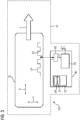
- FIG. 3 shows a further embodiment of a charging station 10, in which a sensor device 40 for locating a vehicle 20 located within the charging station 10 is suitable. Also in the embodiment according to FIG. 3 a sensor device 40 of the charging station 10 and a marking 30 on the vehicle 20 form a positioning system 100, with which the position of the vehicle 20 within the charging station 10 can be determined.
- the surface profile OP of the vehicle-side marker 30 is kept simpler; so is in the FIG. 3
- the vehicle-side marking 30 seen in the vehicle transverse direction or vehicle Y direction has only two profile heights, namely a first profile height at which the surface of the marker 30 has a small distance to the sensor 50 of the sensor device 40 compared to the second profile height and a second profile height at which the surface of the marking 30 has a large distance from the sensor 50 of the sensor device 40 compared to the first profile height.
- the surface profile OP with the marking 30 can be formed, for example, by a perforated or slotted diaphragm.
- a data set D is stored, which defines the surface profile OP of the marking 30 of the vehicle 20.
- the operation of the sensor device 40 according to FIG. 3 corresponds substantially to the operation of the sensor device 40 according to FIG. 1 If the vehicle 20 travels along the direction of travel F into the charging station 10, then the computing device 60 will recognize the occurrence of the marking 30 on the basis of the time profile of the distance signal A (t) so that it can be detected, for example by counting the profile steps or profile jumps. determine the position of the measuring beam M on the surface profile OP of the marker 30 in the vehicle longitudinal direction.
- FIG. 3 a determination of the position of the marker 30 in the vehicle longitudinal direction X alone based on the distance signal A (t) possible, although the marker 30 is designed much simpler than the mark according to the FIG. 1 or 2 ,
- the sensor device 40 can output the distance signal A (t) as well as the vehicle longitudinal direction signal B (t) directly at its output. Alternatively or additionally, by means of the distance signal A (t) and the vehicle longitudinal direction signal B (t), the sensor device 40 can output other locating signals indicating the position of the vehicle 20 within the charging station 10 with respect to reference points of the vehicle 20 other than the mark 30 and / or with respect to reference points other than the position of the sensor device 40 within the charging station 10.
- FIG. 4 shows an embodiment of a charging station 10, in which a sensor device 40 is equipped with two sensors 50 and 51, the function of their function and operation of the sensors 50 according to the FIGS. 1 to 3 correspond.
- the two sensors 50 and 51 respectively generate measurement beams M, respectively receive measurement beams M 'and are each capable of generating a distance signal A1 (t) or A2 (t) which determines the respective distance of the sensor 50 or 51 from the sensor vehicle-side mark 30 indicates.
- the two distance signals A1 (t) and A2 (t) reach the computing device 60, which evaluates them and is able to locate the vehicle 20 both in the transverse direction Y of the vehicle (preferably in the vehicle transverse direction Y) using the data set D or the surface profile OP stored therein Shape of an averaged from the two distance signals A1 (t) and A2 (t) distance signal Am (t)) and in the vehicle X-direction.
- a misdetection of the vehicle 20 may occur in the sensor device 40 according to FIG. 4 be avoided in a particularly simple manner, since by means of the two distance signals A1 (t) and A2 (t) for controlling a direction of travel detection of the vehicle 20 is additionally possible; because By simultaneously evaluating the two distance signals A1 (t) and A2 (t) can be easily seen in which direction of travel F, the vehicle 20 moves at any time. If, after the vehicle 20 retracts into the charging station 10 - for whatever reason - after a vehicle standstill to a reverse drive, this can be detected by the sensor device 40 and used to correct the vehicle longitudinal direction signal B (t).
- sensors 50 and 51 it is possible besides those in the FIGS. 1 to 4 shown sensors 50 and 51 to provide additional sensors which are arranged vertically offset and thus can ensure a detection of the mark 30 even if the vertical positioning of the marker 30 on the vehicle 20 is different than expected or, for example, when lowering or tilting the vehicle 20th is changed at standstill.
- the charging station 10 according to the FIGS. 1 to 4 is equipped in addition to the sensor device 40 described in detail with the usual charging components with which an energy storage of vehicles 10 can be charged.
- Such charging components evaluate the position information of the sensor device 40 for the Loading operation and are the sake of clarity in the FIGS. 1 to 4 not shown.
Landscapes
- Engineering & Computer Science (AREA)
- Physics & Mathematics (AREA)
- Electromagnetism (AREA)
- Power Engineering (AREA)
- Transportation (AREA)
- Mechanical Engineering (AREA)
- Computer Networks & Wireless Communication (AREA)
- General Physics & Mathematics (AREA)
- Radar, Positioning & Navigation (AREA)
- Remote Sensing (AREA)
- Electric Propulsion And Braking For Vehicles (AREA)
- Current-Collector Devices For Electrically Propelled Vehicles (AREA)
- Charge And Discharge Circuits For Batteries Or The Like (AREA)
Description
- Die Erfindung bezieht sich auf ein Ortungssystem zur Bestimmung der Position eines Fahrzeugs beim Einfahren in eine Ladestation, die zum Aufladen eines Energiespeichers des Fahrzeugs geeignet ist.
- Bekanntermaßen können elektrische Energiespeicher von Hybridfahrzeugen oder von ausschließlich elektrisch angetriebenen Fahrzeugen, wie beispielsweise von Bussen des öffentlichen Nahverkehrs, an entsprechend ausgestatteten Haltestellen, nachfolgend Ladestationen genannt, aufgeladen werden. Um den Ladevorgang automatisiert durchführen zu können, sollte die Position des Fahrzeugs innerhalb der Ladestation möglichst genau bekannt sein.
- Der Erfindung liegt demgemäß die Aufgabe zugrunde, ein Ortungssystem anzugeben, das zur Bestimmung der Position eines Fahrzeugs innerhalb einer Ladestation, insbesondere zur Bestimmung der Position beim Einfahren des Fahrzeugs in die Ladestation, geeignet ist und mit dem sich eine Ortsbestimmung besonders einfach, aber dennoch sehr genau durchführen lässt. Diese Aufgabe wird erfindungsgemäß durch ein Ortungssystem mit den Merkmalen gemäß Patentanspruch 1 gelöst. Vorteilhafte Ausgestaltungen des erfindungsgemäßen Ortungssystems sind in Unteransprüchen angegeben.
- Ein Ortungssystem gemäß Oberbegriff von Patentanspruch 1 ist in Dokumenten
EP 2692573 A2 undWO 2011/139680 A2 offenbart. Danach ist erfindungsgemäß vorgesehen, dass das Ortungssystem fahrzeugseitig eine Markierung aufweist, bei der sich zumindest eine Markierungseigenschaft in Fahrzeuglängsrichtung ändert, und die Ortungseinrichtung streckenseitig, insbesondere ladestationsseitig, eine Sensoreinrichtung aufweist, die - beim Vorbeifahren des Fahrzeugs an der Sensoreinrichtung, insbesondere beim Einfahren des Fahrzeugs in die Ladestation - den Abstand der Markierung von der Sensoreinrichtung misst und ein Abstandssignal erzeugt, das den Abstand der Markierung von der Sensoreinrichtung in Fahrzeugquerrichtung angibt, und die Markierungseigenschaft in Fahrzeuglängsrichtung ausliest und ein Fahrzeuglängsrichtungssignal erzeugt, das die Position der Markierung und/oder des Fahrzeugs relativ zur Sensoreinrichtung in Fahrzeuglängsrichtung angibt. - Ein wesentlicher Vorteil des erfindungsgemäßen Ortungssystems ist darin zu sehen, dass eine Bestimmung der Position des Fahrzeugs innerhalb der Ladestation sowohl in Fahrzeuglängsrichtung als auch in Fahrzeugquerrichtung anhand einer Markierung ermittelt werden kann, bei der sich eine Markierungseigenschaft allein in Fahrzeuglängsrichtung ändert. Vorzugsweise wird die fahrzeuglängsrichtungsabhängige Markierungseigenschaft durch die Oberflächentopologie oder zumindest auch durch die Oberflächentopologie der Markierung bestimmt. Die fahrzeuglängsrichtungsabhängige Markierungseigenschaft wird durch das Oberflächenprofil der Markierung in Fahrzeug-Y-Richtung bestimmt und das Fahrzeuglängsrichtungssignal wird durch Auswertung des Abstandssignals erzeugt. Bei dieser Ausgestaltung dient das Abstandssignal mit anderen Worten zur Erzeugung eines zweidimensionalen Positionssignals. Die Oberflächentopologie der Markierung weist in Fahrzeug-Y-Richtung entlang der Fahrzeug-X-Richtung eine Höhenkodierung auf, anhand derer die Position der Markierung in Fahrzeug-X-Richtung relativ zur Sensoreinrichtung feststellbar ist.
- Die Oberflächentopologie der Markierung ist um eine Biegeachse, die der Fahrzeuglängsachse entspricht oder parallel zur Fahrzeuglängsachse liegt, gebogen. Bei einer solchen Ausgestaltung ist eine zuverlässige Markierungserkennung auch noch möglich, wenn sich das Fahrzeug neigt, beispielsweise um bei Fahrzeugstillstand das Einsteigen von Passagieren zu erleichtern.
- Vorzugsweise weist die fahrzeuglängsrichtungsabhängige Markierungseigenschaft der Markierung an dem in Vorwärtsfahrtrichtung des Fahrzeugs gesehen vorderen Markierungsende ein Startmerkmal oder eine Startsequenz auf, anhand derer die Sensoreinrichtung den Beginn des Vorbeifahrens der Markierung erkennt.
- Eine besonders einfache Markierung kann in vorteilhafter Weise durch eine Loch- und/oder Schlitzblende, die ein oder mehrere Löcher und/oder Schlitze enthält, gebildet sein oder eine solche Loch- und/oder Schlitzblende zumindest auch enthalten.
- Die Markierung kann in vorteilhafter Weise darüber hinaus eine Kodierung aufweisen, die das Fahrzeug identifiziert. Im Falle einer solchen Ausgestaltung erkennt die Sensoreinrichtung vorzugsweise anhand der Kodierung das Fahrzeug.
- Die Sensoreinrichtung ist vorzugsweise eine berührungslos arbeitende Sensoreinrichtung. Bevorzugt arbeitet die Sensoreinrichtung optisch, induktiv, magnetisch und/oder kapazitiv.
- Als besonders vorteilhaft wird es angesehen, wenn die Sensoreinrichtung den Abstand zwischen der Markierung und der Sensoreinrichtung mittels eines Triangulationsverfahrens, insbesondere eines Lasertriangulationsverfahrens, oder mittels eines Strahlungslaufzeitverfahrens bestimmt.
- Die Erfindung bezieht sich darüber hinaus auf eine Ladestation, die zum Aufladen eines Energiespeichers eines Fahrzeugs geeignet ist. Bezüglich einer solchen Ladestation ist erfindungsgemäß vorgesehen, dass die Ladestation eine Sensoreinrichtung aufweist, die beim Einfahren des Fahrzeugs in die Ladestation den Abstand einer fahrzeugseitigen Markierung von der Sensoreinrichtung misst und ein Abstandssignal erzeugt, das den Abstand der Markierung von der Sensoreinrichtung in Fahrzeugquerrichtung angibt, und eine Markierungseigenschaft in Fahrzeuglängsrichtung ausliest und ein Fahrzeuglängsrichtungssignal erzeugt, das die Position der Markierung und/oder des Fahrzeugs relativ zur Sensoreinrichtung in Fahrzeuglängsrichtung angibt.
- Bezüglich der Vorteile der erfindungsgemäßen Ladestation sei auf die obigen Erläuterungen im Zusammenhang mit dem erfindungsgemäßen Ortungssystem verwiesen, da die Vorteile des erfindungsgemäßen Ortungssystems denen der erfindungsgemäßen Ladestation im Wesentlichen entsprechen.
- Die Erfindung bezieht sich darüber hinaus auf ein Fahrzeug, das zumindest auch einen Elektroantrieb und einen Energiespeicher aufweist, der über eine Ladestation aufladbar ist. Bezüglich eines solchen Fahrzeugs ist erfindungsgemäß vorgesehen, dass das Fahrzeug eine fahrzeugseitige Markierung mit einer fahrzeuglängsrichtungsabhängigen Markierungseigenschaft aufweist, anhand derer ein Fahrzeuglängsrichtungssignal, das die Position der Markierung und/oder des Fahrzeugs relativ zu einer Sensoreinrichtung der Ladestation in Fahrzeuglängsrichtung angibt, und ein Abstandssignal, das den Abstand der Markierung und/oder des Fahrzeugs von der Sensoreinrichtung in Fahrzeugquerrichtung angibt, erzeugt werden kann.
- Bezüglich der Vorteile des erfindungsgemäßen Fahrzeugs sei auf die obigen Erläuterungen im Zusammenhang mit dem erfindungsgemäßen Ortungssystem verwiesen.
- Die Erfindung bezieht sich darüber hinaus auf ein Verfahren zum Bestimmen der Position eines Fahrzeugs beim Einfahren in eine Ladestation, die zum Aufladen eines Energiespeichers des Fahrzeugs geeignet ist. Erfindungsgemäß ist bezüglich eines solchen Verfahrens vorgesehen, dass beim Vorbeifahren des Fahrzeugs an einer Sensoreinrichtung der Ladestation der Abstand einer fahrzeugseitigen Markierung von der Sensoreinrichtung der Ladestation in Fahrzeugquerrichtung gemessen wird und ein Abstandssignal erzeugt wird, das den Abstand der Markierung und/oder des Fahrzeugs von der Sensoreinrichtung der Ladestation in Fahrzeugquerrichtung angibt, und eine fahrzeuglängsrichtungsabhängige Markierungseigenschaft der fahrzeugseitigen Markierung ausgelesen wird und ein Fahrzeuglängsrichtungssignal erzeugt wird, das die Position der Markierung und/oder des Fahrzeugs relativ zur Sensoreinrichtung der Ladestation in Fahrzeuglängsrichtung angibt.
- Bezüglich der Vorteile des erfindungsgemäßen Verfahrens sei auf die obigen Erläuterungen im Zusammenhang mit dem erfindungsgemäßen Ortungssystem verwiesen.
- Als besonders vorteilhaft wird es angesehen, wenn die fahrzeuglängsrichtungsabhängige Markierungseigenschaft durch das Oberflächenprofil der Markierung in Fahrzeug-Y-Richtung bestimmt wird und das Fahrzeuglängsrichtungssignal durch Auswertung des Abstandssignals erzeugt wird.
- Die Erfindung wird nachfolgend anhand von Ausführungsbeispielen näher erläutert; dabei zeigen beispielhaft:
- Figur 1
- ein Ausführungsbeispiel für eine erfindungsgemäße Ladestation, in die ein mit einer Markierung ausgestattetes Fahrzeug einfährt,
- Figur 2
- ein Ausführungsbeispiel für eine erfindungsgemäße Ladestation, in die ein mit einer Markierung ausgestattetes Fahrzeug einfährt, wobei eine Sensoreinrichtung zusätzlich eine Identifikation des einfahrenden Fahrzeugs vornimmt,
- Figur 3
- ein Ausführungsbeispiel für eine erfindungsgemäße Ladestation, in die ein mit einer - verglichen mit den Markierungen gemäß den
Figuren 1 und2- einfacheren Markierung ausgestattetes Fahrzeug einfährt, und - Figur 4
- ein Ausführungsbeispiel für eine erfindungsgemäße Ladestation, bei der eine Sensoreinrichtung mit zwei in Fahrzeuglängsrichtung versetzt angeordneten Sensoren ausgestattet ist.
- In den Figuren werden der Übersicht halber für identische oder vergleichbare Komponenten stets dieselben Bezugszeichen verwendet.
- Die
Figur 1 zeigt eine Ladestation 10, in die ein Fahrzeug 20 entlang einer für die Ladestation 10 vorgegebenen Fahrtrichtung F einfährt. Das Fahrzeug 20 ist mit einer Markierung 30 versehen, bei der sich eine Markierungseigenschaft in Fahrzeuglängsrichtung X ändert. Bei dem Ausführungsbeispiel gemäßFigur 1 weist die Markierung 30 eine Oberflächentopologie bzw. ein Oberflächenprofil OP auf, dessen - entlang der Fahrzeugquerrichtung bzw. der Fahrzeug-Y-Richtung gesehen - Höhe sich entlang der Fahrzeuglängsrichtung X ändert und somit mathematisch eine Funktion OP(X) der Längskoordinate X darstellt. - Die Markierung 30 kann beispielsweise auf dem Fahrzeugdach des Fahrzeugs 20, an der - in Fahrtrichtung F gesehen - rechten Seitenwand des Fahrzeugs oder auch im Bereich des Fahrzeugbodens des Fahrzeugs 20 angeordnet sein.
- Zur Ortung des Fahrzeugs 20 innerhalb der Ladestation 10 ist die Ladestation 10 mit einer Sensoreinrichtung 40 ausgestattet, die einen Sensor 50, eine Recheneinrichtung 60 sowie einen Speicher 70 umfasst.
- Der Sensor 50 arbeitet vorzugsweise berührungslos, beispielsweise optisch, induktiv, magnetisch und/oder kapazitiv. Beispielsweise kann es sich bei dem Sensor 50 um einen laserbasierten Sensor handeln, der den Abstand zwischen dem Sensor 50 und der fahrzeugseitigen Markierung 30 mittels eines Triangulationsverfahrens, insbesondere eines Lasertriangulationsverfahrens, oder mittels eines Laserstrahlungslaufzeitverfahrens bestimmt.
- In der
Figur 1 ist die Arbeitsweise des Sensors 50 mittels eines Messstrahls M angedeutet, der von dem Sensor 50 Richtung Fahrzeug 20 gestrahlt wird, von der Markierung 30 zumindest teilweise reflektiert wird und als reflektierter Messstrahl M' zurück zum Sensor 50 gelangt. - Die Ladestation 10 bzw. deren Sensoreinrichtung 40 kann beispielsweise wie folgt betrieben werden:
Fährt das Fahrzeug 20 entlang der Fahrtrichtung F in die Ladestation 10 ein, so wird der Sensor 50 anhand des reflektierten Messstrahls M' das Auftreten der Markierung 30 erkennen und ein Abstandssignal A(t) erzeugen, das den Abstand der Markierung 30 von dem Sensor 50 bzw. von der Sensoreinrichtung 40 angibt. - Das Abstandssignal A(t) gelangt zu der Recheneinrichtung 60, die den zeitlichen Verlauf des Abstandssignals A(t) auswertet. Hierzu liest die Recheneinrichtung 60 aus dem Speicher 70 einen Datensatz D aus, der das horizontale Oberflächenprofil OP der geometrischen Markierung 30 mathematisch beschreibt.
- Anhand des Datensatzes D bzw. anhand des ausgelesenen Oberflächenprofils OP sowie anhand des zeitlichen Verlaufs des Abstandssignals A(t) kann die Recheneinrichtung 60 bestimmen, an welcher Stelle auf dem Oberflächenprofil OP sich der Messstrahl M zu jedem Zeitpunkt befindet. Mit anderen Worten ist die Recheneinrichtung 60 also in der Lage, ein Fahrzeuglängsrichtungssignal zu erzeugen, das die Position der Markierung 30 in Fahrzeuglängsrichtung relativ zum Messstrahl M und damit relativ zum Sensor 50 bzw. der Sensoreinrichtung 40 angibt. Das Fahrzeuglängsrichtungssignal ist in der
Figur 1 mit dem Bezugszeichen B(t) gekennzeichnet. - In der Sensoreinrichtung 40 bzw. in der Recheneinrichtung 60 liegen somit zwei Ortsangaben vor, nämlich das Abstandssignal A(t) sowie das Fahrzeugslängsrichtungssignal B(t), die beide gemeinsam die zweidimensionalen Raumkoordinaten der Markierung 30 innerhalb der Ladestation 10 bezogen auf die Position der Sensoreinrichtung 40 angeben.
- Da die Positionierung der Markierung 30 am bzw. auf dem Fahrzeug 20 vorab bekannt ist und vorzugsweise ebenfalls in dem Datensatz D des Speichers 70 oder in einem anderen Datensatz des Speichers 70 hinterlegt ist und da auch die Positionierung der Sensoreinrichtung 40 innerhalb der Ladestation 10 bekannt ist, kann die Recheneinheit 60 zusätzlich oder alternativ zu dem Abstandssignal A(t) und dem Fahrzeuglängsrichtungssignal B(t) auch Ortungssignale erzeugen, die die Positionierung der Markierung 30 bzw. anderer Stellen des Fahrzeugs 20 relativ zur Sensoreinrichtung 40 und/oder relativ zu anderen Referenzpunkten innerhalb der Ladestation 10 beschreiben.
- Mit anderen Worten ist die Sensoreinrichtung 40 bei dem Ausführungsbeispiel gemäß
Figur 1 in der Lage, ausschließlich anhand eines einzigen Messsignals, nämlich des Abstandssignals A(t), das des Abstand der Markierung 30 von der Sensoreinrichtung 40 angibt, die Position des Fahrzeugs 20 innerhalb der Ladestation 10 sowohl in Fahrzeuglängsrichtung X als auch in Fahrzeugquerrichtung Y zu ermitteln. Ein einziges Messsignal ist also ausreichend, um eine zweidimensionale Ortsangabe für das Fahrzeug 20 innerhalb der Ladestation 10 zu erhalten. - Um das Erkennen der Markierung 30 bzw. das Erkennen des Einfahrens des Fahrzeugs 20 in den Bereich der Sensoreinrichtung 40 zu vereinfachen, wird es als vorteilhaft angesehen, wenn die Markierung 30 an ihrem - in Fahrzeuglängsrichtung gesehen - vorderen Ende eine Startsequenz SSQ oder zumindest ein Startmerkmal aufweist, anhand derer bzw. anhand dessen die Sensoreinrichtung 40 den Beginn des Vorbeifahrens der Markierung 30 besonders einfach erkennen kann. Bei dem Ausführungsbeispiel gemäß
Figur 1 wird eine solche Startsequenz durch ein abruptes Ansteigen des Oberflächenprofils OP in Fahrzeug-Y-Richtung bzw. Fahrzeugquerrichtung sowie einen sich daran anschließenden relativ langen Abschnitt konstanten Oberflächenprofils gebildet. - Zur Ortung des Fahrzeugs 20 innerhalb der Ladestation 10 arbeiten die Sensoreinrichtung 40 der Ladestation 10 sowie die Markierung 30 des Fahrzeugs 20 zusammen und bilden gemeinsam ein Ortungssystem 100, das zur Bestimmung der Position des Fahrzeugs 20 in der Ladestation 10 geeignet ist.
- Mittels der sich in Fahrzeuglängsrichtung X ändernden Markierungseigenschaft - bei dem Ausführungsbeispiel gemäß
Figur 1 also mittels des sich in Fahrzeuglängsrichtung X ändernden Oberflächenprofils OP - kann nicht nur eine Bestimmung des Fahrzeuglängsrichtungssignals B(t) mittels des Abstandssignals A(t) erfolgen, wie dies oben im Detail beschrieben worden ist, sondern zusätzlich auch eine Identifikation des Fahrzeugs 20 selbst. Zu diesem Zweck wird innerhalb des Oberflächenprofils OP der Markierung 30 vorzugsweise eine Fahrzeugcodierung implementiert, die von der Recheneinrichtung 60 beim Auslesen und Auswerten des Abstandssignals A(t) erkannt wird und zum Erzeugen eines Identifizierungssignals, das das jeweilige Fahrzeug 20 identifiziert, herangezogen wird. DieFigur 2 zeigt ein solches Ausführungsbeispiel für ein Ortungssystem 100, bei dem die Sensoreinrichtung 40 zusätzlich ein Identifizierungssignal I ausgibt, das mittels des Abstandssignals A(t) gewonnen worden ist und das Fahrzeug 20 identifiziert. - Die
Figur 3 zeigt ein weiteres Ausführungsbeispiel für eine Ladestation 10, bei der eine Sensoreinrichtung 40 zur Ortung eines innerhalb der Ladestation 10 befindlichen Fahrzeugs 20 geeignet ist. Auch bei dem Ausführungsbeispiel gemäßFigur 3 bilden eine Sensoreinrichtung 40 der Ladestation 10 sowie eine Markierung 30 auf dem Fahrzeug 20 ein Ortungssystem 100, mit dem sich die Position des Fahrzeugs 20 innerhalb der Ladestation 10 bestimmen lässt. - Im Unterschied zu dem Ausführungsbeispiel gemäß
Figur 1 ist das Oberflächenprofil OP der fahrzeugseitigen Markierung 30 einfacher gehalten; so ist in derFigur 3 erkennbar, dass die fahrzeugseitige Markierung 30 in Fahrzeugquerrichtung bzw. Fahrzeug-Y-Richtung gesehen lediglich zwei Profilhöhen aufweist, nämlich eine erste Profilhöhe, bei der die Oberfläche der Markierung 30 einen - verglichen mit der zweiten Profilhöhe - kleinen Abstand zum Sensor 50 der Sensoreinrichtung 40 aufweist, und eine zweite Profilhöhe, bei der die Oberfläche der Markierung 30 - verglichen mit der ersten Profilhöhe - einen großen Abstand zum Sensor 50 der Sensoreinrichtung 40 aufweist. Das Oberflächenprofil OP mit der Markierung 30 kann beispielsweise durch eine Loch- oder Schlitzblende gebildet sein. - Um eine Erkennung der Markierung 30 beim Vorbeifahren des Fahrzeugs 20 zu ermöglichen, ist in dem Speicher 70 der Sensoreinrichtung 40 gemäß
Figur 3 vorzugsweise ein Datensatz D abgespeichert, der das Oberflächenprofil OP der Markierung 30 des Fahrzeugs 20 definiert. - Der Betrieb der Sensoreinrichtung 40 gemäß
Figur 3 entspricht im Wesentlichen dem Betrieb der Sensoreinrichtung 40 gemäßFigur 1 : Fährt das Fahrzeug 20 entlang der Fahrtrichtung F in die Ladestation 10 ein, so wird die Recheneinrichtung 60 anhand des zeitlichen Verlaufs des Abstandssignals A(t) das Auftreten der Markierung 30 erkennen, so dass sie - beispielsweise durch Abzählen der Profilstufen bzw. Profilsprünge - die Position des Messstrahls M auf dem Oberflächenprofil OP der Markierung 30 in Fahrzeuglängsrichtung bestimmen kann. - Mit anderen Worten ist auch bei dem Ausführungsbeispiel gemäß
Figur 3 eine Bestimmung der Position der Markierung 30 in Fahrzeuglängsrichtung X allein anhand des Abstandssignals A(t) möglich, obwohl die Markierung 30 deutlich einfacher ausgestaltet ist als die Markierung gemäß derFigur 1 oder2 . - Die Sensoreinrichtung 40 kann das Abstandssignal A(t) sowie das Fahrzeuglängsrichtungssignal B(t) unmittelbar an ihrem Ausgang abgeben. Alternativ oder zusätzlich kann die Sensoreinrichtung 40 mittels des Abstandssignals A(t) und des Fahrzeuglängsrichtungssignals B(t) andere Ortungssignale ausgeben, die die Position des Fahrzeugs 20 innerhalb der Ladestation 10 mit Bezug auf andere Bezugspunkte des Fahrzeugs 20 als die Markierung 30 und/oder mit Bezug auf andere Referenzpunkte als die Position der Sensoreinrichtung 40 innerhalb der Ladestation 10 angeben.
- Die
Figur 4 zeigt ein Ausführungsbeispiel für eine Ladestation 10, bei der eine Sensoreinrichtung 40 mit zwei Sensoren 50 und 51 ausgestattet ist, die von ihrer Funktion und Arbeitsweise den Sensoren 50 gemäß denFiguren 1 bis 3 entsprechen. - Die beiden Sensoren 50 und 51 erzeugen jeweils Messstrahlen M, empfangen jeweils Messstrahlen M' und sind jeweils in der Lage, ein Abstandssignal A1(t) bzw. A2(t) zu erzeugen, das den jeweiligen Abstand des Sensors 50 bzw. 51 von der fahrzeugseitigen Markierung 30 angibt.
- Die beiden Abstandssignale A1(t) und A2(t) gelangen zu der Recheneinrichtung 60, die diese auswertet und anhand des Datensatzes D bzw. des darin abgespeicherten Oberflächenprofils OP in der Lage ist, eine Ortung des Fahrzeugs 20 sowohl in Fahrzeugquerrichtung Y (vorzugsweise in Form eines aus den beiden Abstandssignale A1(t) und A2(t) gemittelten Abstandssignals Am(t)) als auch in Fahrzeug-X-Richtung durchzuführen.
- Eine Fehlmessung bzw. Fehllokalisierung des Fahrzeugs 20 kann bei der Sensoreinrichtung 40 gemäß
Figur 4 in besonders einfacher Weise vermieden werden, da mittels der beiden Abstandssignale A1(t) und A2(t) zur Kontrolle zusätzlich eine Fahrtrichtungserkennung des Fahrzeugs 20 möglich ist; denn durch gleichzeitiges Auswerten der beiden Abstandssignale A1(t) und A2(t) lässt sich ohne weiteres erkennen, in welche Fahrtrichtung F sich das Fahrzeug 20 zu jedem Zeitpunkt bewegt. Kommt es nach dem Einfahren des Fahrzeugs 20 in die Ladestation 10 - aus welchen Gründen auch immer - nach einem Fahrzeugstillstand zu einer Rückwärtsfahrt, so kann dies von der Sensoreinrichtung 40 erkannt und zur Korrektur des Fahrzeuglängsrichtungssignals B(t) herangezogen werden. - Insbesondere bei Bussen des öffentlichen Nahverkehrs ist es nicht unüblich, dass das Fahrzeug bei Stillstand abgesenkt und/oder gekippt wird, um das Ein- und Aussteigen von Passagieren zu vereinfachen. Um auch im Falle eines solchen Absenkens oder Kippens des Fahrzeugs ein zuverlässiges Erkennen und Auslesen der Markierung 30 zu ermöglichen, wird es als vorteilhaft angesehen, wenn die Oberflächentopologie der Markierung 30 um eine Biegeachse, die der Fahrzeuglängsachse X entspricht oder parallel zur Fahrzeuglängsachse X liegt, gebogen ist. Durch eine solche Biegung bzw. Wölbung der Oberflächentopologie bzw. des Oberflächenprofils OP der Markierung 30 lässt sich eine korrekte Erfassung der Markierung 30 auch im Falle eines Absenkens oder Kippens des Fahrzeugs sicherstellen.
- Darüber hinaus ist es möglich, neben den in den
Figuren 1 bis 4 dargestellten Sensoren 50 und 51 weitere Sensoren vorzusehen, die vertikal versetzt angeordnet sind und somit eine Detektion der Markierung 30 auch dann gewährleisten können, wenn die vertikale Positionierung der Markierung 30 auf dem Fahrzeug 20 anders als erwartet ist oder beispielsweise beim Absenken oder Kippen des Fahrzeugs 20 bei Stillstand verändert wird. - Die Ladestation 10 gemäß den
Figuren 1 bis 4 ist neben der im Detail beschriebenen Sensoreinrichtung 40 mit den üblichen Ladekomponenten ausgestattet, mit denen sich ein Energiespeicher der Fahrzeuge 10 aufladen lässt. Solche Ladekomponenten werten die Positionsangaben der Sensoreinrichtung 40 für den Ladebetrieb aus und sind der Übersicht halber in denFiguren 1 bis 4 nicht dargestellt. - Obwohl die Erfindung im Detail durch bevorzugte Ausführungsbeispiele näher illustriert und beschrieben wurde, so ist die Erfindung nicht durch die offenbarten Beispiele eingeschränkt und andere Variationen können vom Fachmann hieraus abgeleitet werden, ohne den Schutzumfang der Erfindung zu verlassen.
Claims (9)
- Ortungssystem (100) zur Bestimmung der Position eines Fahrzeugs (20) beim Einfahren in eine Ladestation (10), die zum Aufladen eines Energiespeichers des Fahrzeugs (20) geeignet ist,
wobei- das Ortungssystem (100) fahrzeugseitig eine Markierung (30) aufweist, bei der sich zumindest eine Markierungseigenschaft in Fahrzeuglängsrichtung (X) ändert, und- die Ortungseinrichtung streckenseitig eine Sensoreinrichtung (40) aufweist, die - beim Vorbeifahren des Fahrzeugs (20) an der Sensoreinrichtung (40) -- den Abstand der Markierung (30) von der Sensoreinrichtung (40) misst und ein Abstandssignal (A(t)) erzeugt, das den Abstand der Markierung (30) von der Sensoreinrichtung (40) in Fahrzeugquerrichtung (Y) angibt, und- die Markierungseigenschaft in Fahrzeuglängsrichtung (X) ausliest und ein Fahrzeuglängsrichtungssignal (B(t)) erzeugt, das die Position der Markierung (30) und/oder des Fahrzeugs (20) relativ zur Sensoreinrichtung (40) in Fahrzeuglängsrichtung (X) angibt, wobei:- die fahrzeuglängsrichtungsabhängige Markierungseigenschaft durch das Oberflächenprofil (OP) der Markierung (30) in Fahrzeugquerrichtung (Y) bestimmt wird und- das Fahrzeuglängsrichtungssignal (B(t)) durch Auswertung des Abstandssignals (A(t)) erzeugt wird, wobei das Oberflächenprofil der Markierung (30) in Fahrzeugquerrichtung (Y) entlang der Fahrzeuglängsrichtung (X) eine Höhenkodierung aufweist, anhand derer die Position der Markierung (30) in Fahrzeuglängsrichtung (X) relativ zur Sensoreinrichtung (40) feststellbar ist und dadurch gekennzeichnet, dass das Oberflächenprofil der Markierung (30) um eine Biegeachse, die der Fahrzeuglängsachse entspricht oder parallel zur Fahrzeuglängsachse liegt, gebogen ist, so dass sich eine korrekte Erfassung der Markierung (30) auch im Falle eines Absenkens oder Kippens des Fahrzeugs sicherstellen lässt. - Ortungssystem (100) nach dem voranstehenden Anspruch,
dadurch gekennzeichnet, dass
die fahrzeuglängsrichtungsabhängige Markierungseigenschaft der Markierung (30) an dem in Vorwärtsfahrtrichtung des Fahrzeugs (20) gesehen vorderen Markierungsende ein Startmerkmal oder eine Startsequenz (SSQ) aufweist, anhand derer die Sensoreinrichtung (40) den Beginn des Vorbeifahrens der Markierung (30) erkennt. - Ortungssystem (100) nach einem der voranstehenden Ansprüche,
dadurch gekennzeichnet, dass
die Markierung (30) durch eine Loch- und/oder Schlitzblende, die ein oder mehrere Löcher und/oder Schlitze enthält, gebildet ist oder eine solche Loch- und/oder Schlitzblende zumindest auch enthält. - Ortungssystem (100) nach einem der voranstehenden Ansprüche,
dadurch gekennzeichnet, dass- die Markierung (30) eine Kodierung aufweist, die das Fahrzeug (20) identifiziert, und- die Sensoreinrichtung (40) anhand der Kodierung das Fahrzeug (20) durch Auswertung des Abstandssignals (A(t)) erkennt. - Ortungssystem (100) nach einem der voranstehenden Ansprüche,
dadurch gekennzeichnet, dass
die Sensoreinrichtung (40) eine berührungslos arbeitende Sensoreinrichtung (40) ist. - Ortungssystem (100) nach einem der voranstehenden Ansprüche,
dadurch gekennzeichnet, dass
die Sensoreinrichtung (40) optisch, induktiv, magnetisch und/oder kapazitiv arbeitet. - Ortungssystem (100) nach einem der voranstehenden Ansprüche,
dadurch gekennzeichnet, dass
die Sensoreinrichtung (40) den Abstand zwischen der Markierung (30) und der Sensoreinrichtung (40) mittels eines Triangulationsverfahrens, insbesondere eines Lasertriangulationsverfahrens, oder mittels eines Strahlungslaufzeitverfahrens bestimmt. - Fahrzeug (20), das zumindest auch einen Elektroantrieb und einen Energiespeicher aufweist, der über eine Ladestation (10) aufladbar ist, wobei
das Fahrzeug (20) eine fahrzeugseitige Markierung (30) mit einer fahrzeuglängsrichtungsabhängigen Markierungseigenschaft aufweist, anhand derer ein Fahrzeuglängsrichtungssignal (B(t)), das die Position der Markierung (30) und/oder des Fahrzeugs (20) relativ zu einer Sensoreinrichtung (40) der Ladestation (10) in Fahrzeuglängsrichtung (X) angibt, und ein Abstandssignal (A(t)), das den Abstand der Markierung (30) und/oder des Fahrzeugs (20) von der Sensoreinrichtung (40) in Fahrzeugquerrichtung (Y) angibt, erzeugt werden kann, wobei die fahrzeuglängsrichtungsabhängige Markierungseigenschaft durch das Oberflächenprofil (OP) der Markierung (30) in Fahrzeugquerrichtung (Y) bestimmt wird, wobei das Oberflächenprofil der Markierung (30) in Fahrzeugquerrichtung (Y) entlang der Fahrzeuglängsrichtung (X) eine Höhenkodierung aufweist, anhand derer die Position der Markierung (30) in Fahrzeuglängsrichtung (X) relativ zur Sensoreinrichtung (40) feststellbar ist und dadurch gekennzeichnet, dass das Oberflächenprofil der Markierung (30) um eine Biegeachse, die der Fahrzeuglängsachse entspricht oder parallel zur Fahrzeuglängsachse liegt, gebogen ist, so dass sich eine korrekte Erfassung der Markierung (30) auch im Falle eines Absenkens oder Kippens des Fahrzeugs sicherstellen lässt. - Verfahren zum Bestimmen der Position eines Fahrzeugs (20) nach Anspruch 8 beim Einfahren in eine Ladestation (10), die zum Aufladen eines Energiespeichers des Fahrzeugs (20) geeignet ist,
dadurch gekennzeichnet, dass- beim Vorbeifahren des Fahrzeugs (20) an einer Sensoreinrichtung (40) der Ladestation (10) der Abstand einer fahrzeugseitigen Markierung (30) von der Sensoreinrichtung (40) der Ladestation (10) in Fahrzeugquerrichtung (Y) gemessen wird und ein Abstandssignal (A(t)) erzeugt wird, das den Abstand der Markierung (30) und/oder des Fahrzeugs (20) von der Sensoreinrichtung (40) der Ladestation (10) in Fahrzeugquerrichtung (Y) angibt, und- eine fahrzeuglängsrichtungsabhängige Markierungseigenschaft der fahrzeugseitigen Markierung (30) ausgelesen wird und ein Fahrzeuglängsrichtungssignal (B(t)) erzeugt wird, das die Position der Markierung (30) und/oder des Fahrzeugs (20) relativ zur Sensoreinrichtung (40) der Ladestation (10) in Fahrzeuglängsrichtung (X) angibt,- die fahrzeuglängsrichtungsabhängige Markierungseigenschaft durch das Oberflächenprofil (OP) der Markierung (30) in Fahrzeugquerrichtung (Y) bestimmt wird und- das Fahrzeuglängsrichtungssignal (B(t)) durch Auswertung des Abstandssignals (A(t)) erzeugt wird.
Priority Applications (1)
| Application Number | Priority Date | Filing Date | Title |
|---|---|---|---|
| PL15726574T PL3126873T3 (pl) | 2014-06-05 | 2015-05-28 | System pozycjonowania do określania pozycji pojazdu w stacji ładowania |
Applications Claiming Priority (2)
| Application Number | Priority Date | Filing Date | Title |
|---|---|---|---|
| DE102014210759.8A DE102014210759A1 (de) | 2014-06-05 | 2014-06-05 | Ortungssystem zur Bestimmung der Position eines Fahrzeugs in einer Ladestation |
| PCT/EP2015/061788 WO2015185429A1 (de) | 2014-06-05 | 2015-05-28 | Ortungssystem zur bestimmung der position eines fahrzeugs in einer ladestation |
Publications (2)
| Publication Number | Publication Date |
|---|---|
| EP3126873A1 EP3126873A1 (de) | 2017-02-08 |
| EP3126873B1 true EP3126873B1 (de) | 2018-06-27 |
Family
ID=53276858
Family Applications (1)
| Application Number | Title | Priority Date | Filing Date |
|---|---|---|---|
| EP15726574.5A Not-in-force EP3126873B1 (de) | 2014-06-05 | 2015-05-28 | Ortungssystem zur bestimmung der position eines fahrzeugs in einer ladestation |
Country Status (7)
| Country | Link |
|---|---|
| US (1) | US10551502B2 (de) |
| EP (1) | EP3126873B1 (de) |
| CN (1) | CN207067404U (de) |
| DE (1) | DE102014210759A1 (de) |
| PL (1) | PL3126873T3 (de) |
| TW (1) | TWI582386B (de) |
| WO (1) | WO2015185429A1 (de) |
Families Citing this family (13)
| Publication number | Priority date | Publication date | Assignee | Title |
|---|---|---|---|---|
| US10352689B2 (en) | 2016-01-28 | 2019-07-16 | Symbol Technologies, Llc | Methods and systems for high precision locationing with depth values |
| JP6602683B2 (ja) * | 2016-02-05 | 2019-11-06 | 株式会社東芝 | 充電装置および位置ずれ検出方法 |
| DE102016205804A1 (de) * | 2016-04-07 | 2017-10-12 | Siemens Aktiengesellschaft | Positionsbestimmungssystem |
| DE102016004582A1 (de) * | 2016-04-14 | 2017-10-19 | Man Truck & Bus Ag | Vorrichtung und Verfahren zum Aufladen eines elektrisch angetriebenen Fahrzeugs |
| EP3543735A4 (de) * | 2016-11-18 | 2020-07-08 | Auto Drive Solutions S.L. | Mit leseempfindlichen sensoren über relative bewegung beider gelesene codierte materialmittel |
| CN110014917A (zh) * | 2017-09-11 | 2019-07-16 | 郑州宇通客车股份有限公司 | 一种自动充电对接控制系统、充电站及汽车 |
| WO2019207499A2 (en) | 2018-04-25 | 2019-10-31 | Tanku LTD. | Method and system for performing fueling operations |
| DE102018207750A1 (de) * | 2018-05-17 | 2019-11-21 | Siemens Aktiengesellschaft | Identifikation eines Fahrzeugs und/oder Ermittlung einer relativen Position des Fahrzeugs gegenüber einer Ladestation |
| US11003972B2 (en) * | 2018-06-27 | 2021-05-11 | Intel Corporation | Localizing a vehicle's charging or fueling port—methods and apparatuses |
| CN109445429A (zh) * | 2018-10-15 | 2019-03-08 | 电子科技大学 | 自动行驶设备的窄通道进入控制方法 |
| CN109398350B (zh) * | 2018-10-19 | 2021-05-28 | 上海蔚来汽车有限公司 | 一种自动泊车方法及用于车辆的自动泊车系统 |
| CN110356277A (zh) * | 2019-08-15 | 2019-10-22 | 上海奥威科技开发有限公司 | 电动汽车充电定位方法及装置 |
| CN113572276B (zh) * | 2021-08-02 | 2024-01-26 | 鲁东大学 | 基于线圈结构进行无线充电对位及信息传递的系统与方法 |
Family Cites Families (48)
| Publication number | Priority date | Publication date | Assignee | Title |
|---|---|---|---|---|
| TW200605B (de) | 1990-09-13 | 1993-02-21 | Daihuku Co Ltd | |
| DE4236286A1 (de) | 1992-10-28 | 1994-05-05 | Daimler Benz Ag | Verfahren und Anordnung zum automatischen berührungslosen Laden |
| DE4411448C5 (de) * | 1994-03-31 | 2009-05-14 | Sick Ag | Verfahren und Vorrichtung zur Kontrolle eines vorgegebenen Überwachungsbereichs |
| US7798417B2 (en) * | 2000-01-03 | 2010-09-21 | Snyder David M | Method for data interchange |
| US7942328B2 (en) * | 2000-01-03 | 2011-05-17 | Roelesis Wireless Llc | Method for data interchange |
| US7350708B2 (en) * | 2000-01-03 | 2008-04-01 | Tripletail Ventures, Inc. | Method for data interchange |
| US8831970B2 (en) * | 2000-08-24 | 2014-09-09 | Martin Herman Weik, III | Virtual attendant system and parking management system |
| US9919723B2 (en) * | 2002-06-04 | 2018-03-20 | General Electric Company | Aerial camera system and method for determining size parameters of vehicle systems |
| US7382277B2 (en) * | 2003-02-12 | 2008-06-03 | Edward D. Ioli Trust | System for tracking suspicious vehicular activity |
| US7774268B2 (en) * | 2003-03-03 | 2010-08-10 | The Tb Group, Inc. | System, method, and apparatus for identifying and authenticating the presence of high value assets at remote locations |
| US7281666B2 (en) * | 2004-03-05 | 2007-10-16 | Joseph C Smith | Automobile identification device |
| US7525435B2 (en) * | 2005-08-02 | 2009-04-28 | Performance Partners, Llc | Method, apparatus, and system for securing areas of use of vehicles |
| US8292168B2 (en) * | 2005-10-24 | 2012-10-23 | Petratec International Ltd. | System and method for authorizing purchases associated with a vehicle |
| US20070108288A1 (en) * | 2005-11-16 | 2007-05-17 | Caskey Gregory T | Method and apparatus for novel reading of surface structure bar codes |
| US9430732B2 (en) * | 2014-05-08 | 2016-08-30 | Tego, Inc. | Three-dimension RFID tag with opening through structure |
| US20070229307A1 (en) * | 2006-03-31 | 2007-10-04 | Ivan Pawlenko | Detection technology for vehicular and other security applications |
| US8010219B2 (en) * | 2006-05-05 | 2011-08-30 | Tc License, Ltd. | Computer automated test and processing system of RFID tags |
| US8727208B2 (en) * | 2006-06-30 | 2014-05-20 | Intel-Ge Care Innovations Llc | Method for identifying pills via an optical device |
| US7791481B2 (en) * | 2007-01-22 | 2010-09-07 | Tc License Ltd. | Light activated RFID tag |
| US8872622B2 (en) * | 2007-03-27 | 2014-10-28 | Valmarc Corporation | Authentication of “source” for brands |
| WO2009050662A1 (en) * | 2007-10-19 | 2009-04-23 | Petratec International Ltd. | Rfid tag especially for use near conductive objects |
| WO2009124565A1 (de) * | 2008-04-10 | 2009-10-15 | Draka Industrial Cable Gmbh | Verfahren und vorrichtung zum berührungslosen messen eines versatzes der funktionskomponenten eines fahrweges einer mit einem linearmotor angetriebenen magnetschwebebahn |
| US8196817B2 (en) * | 2008-11-07 | 2012-06-12 | Mastercard International Incorporated | Systems and methods for facilitating payment transactions using a financial transaction card |
| DE102009033236A1 (de) | 2009-07-14 | 2011-01-20 | Conductix-Wampfler Ag | Vorrichtung zur induktiven Übertragung elektrischer Energie |
| CA2767279A1 (en) | 2009-07-15 | 2011-01-20 | Conductix-Wampfler Ag | System for inductively charging vehicles, comprising an electronic positioning aid |
| DE102009049432B4 (de) | 2009-10-14 | 2024-11-28 | Sew-Eurodrive Gmbh & Co Kg | Ladestation |
| CN103038975B (zh) | 2010-04-26 | 2016-09-14 | 普罗特拉公司 | 用于电动车在充电站自动连接和充电的系统与方法 |
| US8918898B2 (en) * | 2010-07-30 | 2014-12-23 | Certusview Technologies, Llc | Methods, apparatus and systems for onsite linking to location-specific electronic records of locate operations |
| US8509982B2 (en) * | 2010-10-05 | 2013-08-13 | Google Inc. | Zone driving |
| WO2012049438A1 (en) * | 2010-10-12 | 2012-04-19 | Stephen James Crampton | Hover cmm |
| US8873807B2 (en) * | 2011-03-08 | 2014-10-28 | Bank Of America Corporation | Vehicle recognition |
| US9410823B2 (en) | 2012-07-13 | 2016-08-09 | Qualcomm Incorporated | Systems, methods, and apparatus for detection of metal objects in a predetermined space |
| DE102012015262A1 (de) * | 2012-08-01 | 2014-02-06 | Audi Ag | Verfahren zum Positionieren eines Kraftwagens, System mit einem solchen Kraftwagen sowie Kraftwagen |
| WO2014076699A1 (en) * | 2012-11-13 | 2014-05-22 | Fuel Vision Ltd. | System and method for securing fuel transactions by image recognition and processing |
| US20140191718A1 (en) * | 2013-01-09 | 2014-07-10 | Stacey Reineccius | Secure authentication for fueling of vehicles |
| US9792473B2 (en) * | 2013-01-10 | 2017-10-17 | Weixi Luo | Card swiping method and device for determining mobile terminal for swiping card, utilizing intensity of ultrasonic signal |
| US9805538B2 (en) * | 2013-03-15 | 2017-10-31 | Zonar Systems, Inc. | Method and apparatus for fuel island authorization for trucking industry using proximity sensors |
| US20140379385A1 (en) * | 2013-06-24 | 2014-12-25 | Elwha, Llc | System and method for monitoring driving to determine an insurance property |
| US9405988B2 (en) * | 2013-08-13 | 2016-08-02 | James Alves | License plate recognition |
| US9626690B2 (en) * | 2013-09-18 | 2017-04-18 | Lidong Qu | System and method for using data tags to manage tasks and rewards in providing object-to-object services |
| WO2015154171A1 (en) * | 2014-04-08 | 2015-10-15 | Transponder Concepts Llc | Bridgeless antenna, and method of manufacture |
| EP2960883B1 (de) * | 2014-06-23 | 2017-08-09 | VITRONIC Dr.-Ing. Stein Bildverarbeitungssysteme GmbH | Bestimmung mindestens eines Merkmals eines Fahrzeugs |
| US10219140B2 (en) * | 2014-06-30 | 2019-02-26 | Nokia Technologies Oy | Vehicle communication identifiers based on license plate information |
| US20170148101A1 (en) * | 2015-11-23 | 2017-05-25 | CSI Holdings I LLC | Damage assessment and repair based on objective surface data |
| US10319166B2 (en) * | 2016-05-05 | 2019-06-11 | Visa International Service Assocation | Vehicle-based identification and access |
| US9886855B2 (en) * | 2016-05-24 | 2018-02-06 | General Motors Llc | Systems and methods for monitoring a parking space |
| US20180010954A1 (en) * | 2016-07-11 | 2018-01-11 | Dublin Lowndes, LLC | Material handling system |
| US10389429B2 (en) * | 2017-02-11 | 2019-08-20 | Massachusetts Institute Of Technology | Full-duplex, bi-directional, analog relay |
-
2014
- 2014-06-05 DE DE102014210759.8A patent/DE102014210759A1/de not_active Ceased
-
2015
- 2015-05-28 EP EP15726574.5A patent/EP3126873B1/de not_active Not-in-force
- 2015-05-28 PL PL15726574T patent/PL3126873T3/pl unknown
- 2015-05-28 US US15/313,578 patent/US10551502B2/en not_active Expired - Fee Related
- 2015-05-28 CN CN201590000693.2U patent/CN207067404U/zh not_active Expired - Fee Related
- 2015-05-28 WO PCT/EP2015/061788 patent/WO2015185429A1/de not_active Ceased
- 2015-06-03 TW TW104117982A patent/TWI582386B/zh not_active IP Right Cessation
Non-Patent Citations (1)
| Title |
|---|
| None * |
Also Published As
| Publication number | Publication date |
|---|---|
| DE102014210759A1 (de) | 2015-12-17 |
| TWI582386B (zh) | 2017-05-11 |
| US20170212237A1 (en) | 2017-07-27 |
| US10551502B2 (en) | 2020-02-04 |
| EP3126873A1 (de) | 2017-02-08 |
| CN207067404U (zh) | 2018-03-02 |
| PL3126873T3 (pl) | 2018-10-31 |
| TW201602518A (zh) | 2016-01-16 |
| WO2015185429A1 (de) | 2015-12-10 |
Similar Documents
| Publication | Publication Date | Title |
|---|---|---|
| DE102014210759A1 (de) | Ortungssystem zur Bestimmung der Position eines Fahrzeugs in einer Ladestation | |
| EP3442849B1 (de) | Verfahren und messsystem zum erfassen eines festpunktes neben einem gleis | |
| DE102010030213B4 (de) | Einparkhilfesystem für Querparklücken | |
| EP3523177B1 (de) | Verfahren, vorrichtung und bahnfahrzeug, insbesondere schienenfahrzeug, zur hinderniserkennung im bahnverkehr, insbesondere im schienenverkehr | |
| EP2684070B1 (de) | Verfahren zum detektieren einer parklücke, parkhilfesystem und kraftfahrzeug mit einem parkhilfesystem | |
| DE102017007511B3 (de) | Vorrichtung und Verfahren zur Erhaltung der Präzision der Navigations-Fähigkeit eines fahrerlosen Transportfahrzeugs | |
| EP3665502B1 (de) | Verfahren zum überwachen eines umgebungsbereiches eines kraftfahrzeugs, sensorsteuergerät, fahrerassistenzsystem sowie kraftfahrzeug | |
| DE112017004946B4 (de) | Parksteuervorrichtung und Parksteuerverfahren | |
| WO2009013054A1 (de) | Objektklassifizierungsverfahren und einparkhilfesystem | |
| EP3007024B1 (de) | Verfahren zur positionierung eines kraftfahrzeugs zum kontaktlosen laden und kraftfahrzeug | |
| DE112017004858T5 (de) | Verfahren zum Bestimmen des Vorhandenseins eines Anhängers | |
| EP2963631B1 (de) | Verfahren zum ermitteln eines parkplatzes aus einer anzahl von messpunkten | |
| DE102013017347A1 (de) | Verfahren zum Klassifizieren von Hindernissen | |
| DE102016122294A1 (de) | Planen einer Trajektorie zum autonomen Parken eines Kraftfahrzeugs in einer Parkplatzumgebung | |
| EP3295117A1 (de) | Vorrichtung zur bestimmung eines für ein fahrzeug befahrbaren raums, entsprechendes verfahren und fahrzeug | |
| DE102017212376A1 (de) | Verfahren und System zum Detektieren eines freien Bereiches innerhalb eines Parkplatzes | |
| DE102018009114A1 (de) | Verfahren zur Bestimmung der Position eines auf einer Verfahrfläche bewegbaren Mobilteils und Anlage mit Mobilteil zur Durchführung des Verfahrens | |
| EP2887093A1 (de) | Verfahren zum Klassifizieren eines Objekts, Sensoreinrichtung und Kraftfahrzeug | |
| EP3515787B1 (de) | Verfahren zur positionsbestimmung eines schienenfahrzeugs und schienenfahrzeug mit positionsbestimmungseinrichtung | |
| DE102020215149A1 (de) | Verfahren zum Betreiben eines Fahrzeugs in einem Regalgang in Abhängigkeit von einer Fahrweginformation | |
| EP2812647B1 (de) | Verfahren und anordnung zum vermessen von abständen eines schienenfahrzeugs zu seitlich des schienenfahrzeugs angeordneten gegenständen | |
| EP3520020A1 (de) | Verkehrszeichenklassifikation in einem umgebungsbereich eines kraftfahrzeugs | |
| DE102020121785B4 (de) | Verfahren zum Manövrieren eines Fahrzeugs in eine Schrägparklücke mit Vermeidung einer Kollision einer Frontschürze des Fahrzeugs mit einer Begrenzung der Schrägparklücke, Fahrerassistenzsystem sowie Fahrzeug | |
| DE102008051691A1 (de) | Vorrichtung zur Erkennung einer auf einem Fahrzeugdach eines Fahrzeuges angeordneten Dachlast | |
| DE102007060856A1 (de) | Verfahren und Sensoranordnung zur Ermittlung von Fahrspuren |
Legal Events
| Date | Code | Title | Description |
|---|---|---|---|
| STAA | Information on the status of an ep patent application or granted ep patent |
Free format text: STATUS: THE INTERNATIONAL PUBLICATION HAS BEEN MADE |
|
| PUAI | Public reference made under article 153(3) epc to a published international application that has entered the european phase |
Free format text: ORIGINAL CODE: 0009012 |
|
| STAA | Information on the status of an ep patent application or granted ep patent |
Free format text: STATUS: REQUEST FOR EXAMINATION WAS MADE |
|
| 17P | Request for examination filed |
Effective date: 20161103 |
|
| AK | Designated contracting states |
Kind code of ref document: A1 Designated state(s): AL AT BE BG CH CY CZ DE DK EE ES FI FR GB GR HR HU IE IS IT LI LT LU LV MC MK MT NL NO PL PT RO RS SE SI SK SM TR |
|
| AX | Request for extension of the european patent |
Extension state: BA ME |
|
| RAP1 | Party data changed (applicant data changed or rights of an application transferred) |
Owner name: SIEMENS AKTIENGESELLSCHAFT |
|
| DAV | Request for validation of the european patent (deleted) | ||
| DAX | Request for extension of the european patent (deleted) | ||
| GRAP | Despatch of communication of intention to grant a patent |
Free format text: ORIGINAL CODE: EPIDOSNIGR1 |
|
| STAA | Information on the status of an ep patent application or granted ep patent |
Free format text: STATUS: GRANT OF PATENT IS INTENDED |
|
| INTG | Intention to grant announced |
Effective date: 20180223 |
|
| GRAS | Grant fee paid |
Free format text: ORIGINAL CODE: EPIDOSNIGR3 |
|
| GRAA | (expected) grant |
Free format text: ORIGINAL CODE: 0009210 |
|
| STAA | Information on the status of an ep patent application or granted ep patent |
Free format text: STATUS: THE PATENT HAS BEEN GRANTED |
|
| AK | Designated contracting states |
Kind code of ref document: B1 Designated state(s): AL AT BE BG CH CY CZ DE DK EE ES FI FR GB GR HR HU IE IS IT LI LT LU LV MC MK MT NL NO PL PT RO RS SE SI SK SM TR |
|
| REG | Reference to a national code |
Ref country code: GB Ref legal event code: FG4D Free format text: NOT ENGLISH |
|
| REG | Reference to a national code |
Ref country code: AT Ref legal event code: REF Ref document number: 1012801 Country of ref document: AT Kind code of ref document: T Effective date: 20180715 |
|
| REG | Reference to a national code |
Ref country code: IE Ref legal event code: FG4D Free format text: LANGUAGE OF EP DOCUMENT: GERMAN |
|
| REG | Reference to a national code |
Ref country code: DE Ref legal event code: R096 Ref document number: 502015004848 Country of ref document: DE |
|
| REG | Reference to a national code |
Ref country code: SE Ref legal event code: TRGR |
|
| REG | Reference to a national code |
Ref country code: NL Ref legal event code: FP |
|
| REG | Reference to a national code |
Ref country code: CH Ref legal event code: PUE Owner name: SIEMENS MOBILITY GMBH, DE Free format text: FORMER OWNER: SIEMENS AKTIENGESELLSCHAFT, DE |
|
| PG25 | Lapsed in a contracting state [announced via postgrant information from national office to epo] |
Ref country code: FI Free format text: LAPSE BECAUSE OF FAILURE TO SUBMIT A TRANSLATION OF THE DESCRIPTION OR TO PAY THE FEE WITHIN THE PRESCRIBED TIME-LIMIT Effective date: 20180627 Ref country code: NO Free format text: LAPSE BECAUSE OF FAILURE TO SUBMIT A TRANSLATION OF THE DESCRIPTION OR TO PAY THE FEE WITHIN THE PRESCRIBED TIME-LIMIT Effective date: 20180927 Ref country code: LT Free format text: LAPSE BECAUSE OF FAILURE TO SUBMIT A TRANSLATION OF THE DESCRIPTION OR TO PAY THE FEE WITHIN THE PRESCRIBED TIME-LIMIT Effective date: 20180627 Ref country code: BG Free format text: LAPSE BECAUSE OF FAILURE TO SUBMIT A TRANSLATION OF THE DESCRIPTION OR TO PAY THE FEE WITHIN THE PRESCRIBED TIME-LIMIT Effective date: 20180927 |
|
| RAP2 | Party data changed (patent owner data changed or rights of a patent transferred) |
Owner name: SIEMENS MOBILITY GMBH |
|
| REG | Reference to a national code |
Ref country code: CH Ref legal event code: NV Representative=s name: SIEMENS SCHWEIZ AG, CH |
|
| REG | Reference to a national code |
Ref country code: LT Ref legal event code: MG4D |
|
| PG25 | Lapsed in a contracting state [announced via postgrant information from national office to epo] |
Ref country code: GR Free format text: LAPSE BECAUSE OF FAILURE TO SUBMIT A TRANSLATION OF THE DESCRIPTION OR TO PAY THE FEE WITHIN THE PRESCRIBED TIME-LIMIT Effective date: 20180928 Ref country code: HR Free format text: LAPSE BECAUSE OF FAILURE TO SUBMIT A TRANSLATION OF THE DESCRIPTION OR TO PAY THE FEE WITHIN THE PRESCRIBED TIME-LIMIT Effective date: 20180627 Ref country code: RS Free format text: LAPSE BECAUSE OF FAILURE TO SUBMIT A TRANSLATION OF THE DESCRIPTION OR TO PAY THE FEE WITHIN THE PRESCRIBED TIME-LIMIT Effective date: 20180627 Ref country code: LV Free format text: LAPSE BECAUSE OF FAILURE TO SUBMIT A TRANSLATION OF THE DESCRIPTION OR TO PAY THE FEE WITHIN THE PRESCRIBED TIME-LIMIT Effective date: 20180627 |
|
| REG | Reference to a national code |
Ref country code: DE Ref legal event code: R081 Ref document number: 502015004848 Country of ref document: DE Owner name: SIEMENS MOBILITY GMBH, DE Free format text: FORMER OWNER: SIEMENS AKTIENGESELLSCHAFT, 80333 MUENCHEN, DE |
|
| PG25 | Lapsed in a contracting state [announced via postgrant information from national office to epo] |
Ref country code: SK Free format text: LAPSE BECAUSE OF FAILURE TO SUBMIT A TRANSLATION OF THE DESCRIPTION OR TO PAY THE FEE WITHIN THE PRESCRIBED TIME-LIMIT Effective date: 20180627 Ref country code: CZ Free format text: LAPSE BECAUSE OF FAILURE TO SUBMIT A TRANSLATION OF THE DESCRIPTION OR TO PAY THE FEE WITHIN THE PRESCRIBED TIME-LIMIT Effective date: 20180627 Ref country code: RO Free format text: LAPSE BECAUSE OF FAILURE TO SUBMIT A TRANSLATION OF THE DESCRIPTION OR TO PAY THE FEE WITHIN THE PRESCRIBED TIME-LIMIT Effective date: 20180627 Ref country code: EE Free format text: LAPSE BECAUSE OF FAILURE TO SUBMIT A TRANSLATION OF THE DESCRIPTION OR TO PAY THE FEE WITHIN THE PRESCRIBED TIME-LIMIT Effective date: 20180627 Ref country code: IS Free format text: LAPSE BECAUSE OF FAILURE TO SUBMIT A TRANSLATION OF THE DESCRIPTION OR TO PAY THE FEE WITHIN THE PRESCRIBED TIME-LIMIT Effective date: 20181027 |
|
| PG25 | Lapsed in a contracting state [announced via postgrant information from national office to epo] |
Ref country code: SM Free format text: LAPSE BECAUSE OF FAILURE TO SUBMIT A TRANSLATION OF THE DESCRIPTION OR TO PAY THE FEE WITHIN THE PRESCRIBED TIME-LIMIT Effective date: 20180627 Ref country code: IT Free format text: LAPSE BECAUSE OF FAILURE TO SUBMIT A TRANSLATION OF THE DESCRIPTION OR TO PAY THE FEE WITHIN THE PRESCRIBED TIME-LIMIT Effective date: 20180627 Ref country code: ES Free format text: LAPSE BECAUSE OF FAILURE TO SUBMIT A TRANSLATION OF THE DESCRIPTION OR TO PAY THE FEE WITHIN THE PRESCRIBED TIME-LIMIT Effective date: 20180627 |
|
| REG | Reference to a national code |
Ref country code: GB Ref legal event code: 732E Free format text: REGISTERED BETWEEN 20190207 AND 20190213 |
|
| REG | Reference to a national code |
Ref country code: DE Ref legal event code: R097 Ref document number: 502015004848 Country of ref document: DE |
|
| PLBE | No opposition filed within time limit |
Free format text: ORIGINAL CODE: 0009261 |
|
| STAA | Information on the status of an ep patent application or granted ep patent |
Free format text: STATUS: NO OPPOSITION FILED WITHIN TIME LIMIT |
|
| PG25 | Lapsed in a contracting state [announced via postgrant information from national office to epo] |
Ref country code: DK Free format text: LAPSE BECAUSE OF FAILURE TO SUBMIT A TRANSLATION OF THE DESCRIPTION OR TO PAY THE FEE WITHIN THE PRESCRIBED TIME-LIMIT Effective date: 20180627 |
|
| 26N | No opposition filed |
Effective date: 20190328 |
|
| REG | Reference to a national code |
Ref country code: AT Ref legal event code: PC Ref document number: 1012801 Country of ref document: AT Kind code of ref document: T Owner name: SIEMENS MOBILITY GMBH, DE Effective date: 20190506 |
|
| PGFP | Annual fee paid to national office [announced via postgrant information from national office to epo] |
Ref country code: NL Payment date: 20190513 Year of fee payment: 5 |
|
| PGFP | Annual fee paid to national office [announced via postgrant information from national office to epo] |
Ref country code: PL Payment date: 20190426 Year of fee payment: 5 |
|
| PG25 | Lapsed in a contracting state [announced via postgrant information from national office to epo] |
Ref country code: SI Free format text: LAPSE BECAUSE OF FAILURE TO SUBMIT A TRANSLATION OF THE DESCRIPTION OR TO PAY THE FEE WITHIN THE PRESCRIBED TIME-LIMIT Effective date: 20180627 |
|
| PGFP | Annual fee paid to national office [announced via postgrant information from national office to epo] |
Ref country code: SE Payment date: 20190510 Year of fee payment: 5 Ref country code: FR Payment date: 20190517 Year of fee payment: 5 |
|
| REG | Reference to a national code |
Ref country code: NL Ref legal event code: PD Owner name: SIEMENS MOBILITY GMBH; DE Free format text: DETAILS ASSIGNMENT: CHANGE OF OWNER(S), ASSIGNMENT; FORMER OWNER NAME: SIEMENS AKTIENGESELLSCHAFT Effective date: 20190829 |
|
| PGFP | Annual fee paid to national office [announced via postgrant information from national office to epo] |
Ref country code: GB Payment date: 20190509 Year of fee payment: 5 Ref country code: DE Payment date: 20190719 Year of fee payment: 5 |
|
| PG25 | Lapsed in a contracting state [announced via postgrant information from national office to epo] |
Ref country code: AL Free format text: LAPSE BECAUSE OF FAILURE TO SUBMIT A TRANSLATION OF THE DESCRIPTION OR TO PAY THE FEE WITHIN THE PRESCRIBED TIME-LIMIT Effective date: 20180627 |
|
| PG25 | Lapsed in a contracting state [announced via postgrant information from national office to epo] |
Ref country code: MC Free format text: LAPSE BECAUSE OF FAILURE TO SUBMIT A TRANSLATION OF THE DESCRIPTION OR TO PAY THE FEE WITHIN THE PRESCRIBED TIME-LIMIT Effective date: 20180627 |
|
| PGFP | Annual fee paid to national office [announced via postgrant information from national office to epo] |
Ref country code: CH Payment date: 20190802 Year of fee payment: 5 |
|
| REG | Reference to a national code |
Ref country code: BE Ref legal event code: MM Effective date: 20190531 |
|
| PG25 | Lapsed in a contracting state [announced via postgrant information from national office to epo] |
Ref country code: LU Free format text: LAPSE BECAUSE OF NON-PAYMENT OF DUE FEES Effective date: 20190528 |
|
| PG25 | Lapsed in a contracting state [announced via postgrant information from national office to epo] |
Ref country code: TR Free format text: LAPSE BECAUSE OF FAILURE TO SUBMIT A TRANSLATION OF THE DESCRIPTION OR TO PAY THE FEE WITHIN THE PRESCRIBED TIME-LIMIT Effective date: 20180627 |
|
| PG25 | Lapsed in a contracting state [announced via postgrant information from national office to epo] |
Ref country code: IE Free format text: LAPSE BECAUSE OF NON-PAYMENT OF DUE FEES Effective date: 20190528 |
|
| PG25 | Lapsed in a contracting state [announced via postgrant information from national office to epo] |
Ref country code: BE Free format text: LAPSE BECAUSE OF NON-PAYMENT OF DUE FEES Effective date: 20190531 |
|
| PG25 | Lapsed in a contracting state [announced via postgrant information from national office to epo] |
Ref country code: PT Free format text: LAPSE BECAUSE OF FAILURE TO SUBMIT A TRANSLATION OF THE DESCRIPTION OR TO PAY THE FEE WITHIN THE PRESCRIBED TIME-LIMIT Effective date: 20181029 |
|
| REG | Reference to a national code |
Ref country code: DE Ref legal event code: R119 Ref document number: 502015004848 Country of ref document: DE |
|
| REG | Reference to a national code |
Ref country code: NL Ref legal event code: MM Effective date: 20200601 |
|
| PG25 | Lapsed in a contracting state [announced via postgrant information from national office to epo] |
Ref country code: SE Free format text: LAPSE BECAUSE OF NON-PAYMENT OF DUE FEES Effective date: 20200529 Ref country code: LI Free format text: LAPSE BECAUSE OF NON-PAYMENT OF DUE FEES Effective date: 20200531 Ref country code: CH Free format text: LAPSE BECAUSE OF NON-PAYMENT OF DUE FEES Effective date: 20200531 |
|
| PG25 | Lapsed in a contracting state [announced via postgrant information from national office to epo] |
Ref country code: NL Free format text: LAPSE BECAUSE OF NON-PAYMENT OF DUE FEES Effective date: 20200601 |
|
| GBPC | Gb: european patent ceased through non-payment of renewal fee |
Effective date: 20200528 |
|
| PG25 | Lapsed in a contracting state [announced via postgrant information from national office to epo] |
Ref country code: GB Free format text: LAPSE BECAUSE OF NON-PAYMENT OF DUE FEES Effective date: 20200528 Ref country code: FR Free format text: LAPSE BECAUSE OF NON-PAYMENT OF DUE FEES Effective date: 20200531 |
|
| PG25 | Lapsed in a contracting state [announced via postgrant information from national office to epo] |
Ref country code: CY Free format text: LAPSE BECAUSE OF FAILURE TO SUBMIT A TRANSLATION OF THE DESCRIPTION OR TO PAY THE FEE WITHIN THE PRESCRIBED TIME-LIMIT Effective date: 20180627 Ref country code: DE Free format text: LAPSE BECAUSE OF NON-PAYMENT OF DUE FEES Effective date: 20201201 |
|
| REG | Reference to a national code |
Ref country code: AT Ref legal event code: MM01 Ref document number: 1012801 Country of ref document: AT Kind code of ref document: T Effective date: 20200528 |
|
| PG25 | Lapsed in a contracting state [announced via postgrant information from national office to epo] |
Ref country code: MT Free format text: LAPSE BECAUSE OF FAILURE TO SUBMIT A TRANSLATION OF THE DESCRIPTION OR TO PAY THE FEE WITHIN THE PRESCRIBED TIME-LIMIT Effective date: 20180627 Ref country code: HU Free format text: LAPSE BECAUSE OF FAILURE TO SUBMIT A TRANSLATION OF THE DESCRIPTION OR TO PAY THE FEE WITHIN THE PRESCRIBED TIME-LIMIT; INVALID AB INITIO Effective date: 20150528 |
|
| PG25 | Lapsed in a contracting state [announced via postgrant information from national office to epo] |
Ref country code: AT Free format text: LAPSE BECAUSE OF NON-PAYMENT OF DUE FEES Effective date: 20200528 |
|
| PG25 | Lapsed in a contracting state [announced via postgrant information from national office to epo] |
Ref country code: MK Free format text: LAPSE BECAUSE OF FAILURE TO SUBMIT A TRANSLATION OF THE DESCRIPTION OR TO PAY THE FEE WITHIN THE PRESCRIBED TIME-LIMIT Effective date: 20180627 |
|
| PG25 | Lapsed in a contracting state [announced via postgrant information from national office to epo] |
Ref country code: PL Free format text: LAPSE BECAUSE OF NON-PAYMENT OF DUE FEES Effective date: 20200528 |