EP3126591B1 - Halteelement aus einem einstellknopf und einer stange mit einstellung der länge der stange über den einstellknopf hinaus - Google Patents
Halteelement aus einem einstellknopf und einer stange mit einstellung der länge der stange über den einstellknopf hinaus Download PDFInfo
- Publication number
- EP3126591B1 EP3126591B1 EP15719499.4A EP15719499A EP3126591B1 EP 3126591 B1 EP3126591 B1 EP 3126591B1 EP 15719499 A EP15719499 A EP 15719499A EP 3126591 B1 EP3126591 B1 EP 3126591B1
- Authority
- EP
- European Patent Office
- Prior art keywords
- rod
- holding element
- adjusting knob
- securing
- wheel
- Prior art date
- Legal status (The legal status is an assumption and is not a legal conclusion. Google has not performed a legal analysis and makes no representation as to the accuracy of the status listed.)
- Active
Links
- 238000010276 construction Methods 0.000 claims description 13
- 210000000078 claw Anatomy 0.000 claims description 9
- 238000006073 displacement reaction Methods 0.000 claims description 8
- 238000000034 method Methods 0.000 claims description 6
- 125000006850 spacer group Chemical group 0.000 claims description 6
- 230000000149 penetrating effect Effects 0.000 claims description 4
- 238000003780 insertion Methods 0.000 claims 1
- 230000037431 insertion Effects 0.000 claims 1
- 238000009877 rendering Methods 0.000 claims 1
- 238000012423 maintenance Methods 0.000 description 6
- 239000002184 metal Substances 0.000 description 4
- 208000031968 Cadaver Diseases 0.000 description 3
- 230000006870 function Effects 0.000 description 3
- 239000004033 plastic Substances 0.000 description 3
- 230000000903 blocking effect Effects 0.000 description 2
- 230000000694 effects Effects 0.000 description 2
- 239000000463 material Substances 0.000 description 2
- 230000003014 reinforcing effect Effects 0.000 description 2
- 101100536354 Drosophila melanogaster tant gene Proteins 0.000 description 1
- 239000004743 Polypropylene Substances 0.000 description 1
- 230000006978 adaptation Effects 0.000 description 1
- 230000000295 complement effect Effects 0.000 description 1
- 230000006835 compression Effects 0.000 description 1
- 238000007906 compression Methods 0.000 description 1
- 230000003247 decreasing effect Effects 0.000 description 1
- 239000003365 glass fiber Substances 0.000 description 1
- 239000011491 glass wool Substances 0.000 description 1
- 238000009434 installation Methods 0.000 description 1
- 238000009413 insulation Methods 0.000 description 1
- 239000012212 insulator Substances 0.000 description 1
- 230000002452 interceptive effect Effects 0.000 description 1
- 230000009916 joint effect Effects 0.000 description 1
- 238000004519 manufacturing process Methods 0.000 description 1
- 210000000056 organ Anatomy 0.000 description 1
- -1 polypropylene Polymers 0.000 description 1
- 229920001155 polypropylene Polymers 0.000 description 1
- 230000000284 resting effect Effects 0.000 description 1
- 238000000926 separation method Methods 0.000 description 1
Images


Classifications
-
- E—FIXED CONSTRUCTIONS
- E04—BUILDING
- E04F—FINISHING WORK ON BUILDINGS, e.g. STAIRS, FLOORS
- E04F13/00—Coverings or linings, e.g. for walls or ceilings
- E04F13/07—Coverings or linings, e.g. for walls or ceilings composed of covering or lining elements; Sub-structures therefor; Fastening means therefor
- E04F13/08—Coverings or linings, e.g. for walls or ceilings composed of covering or lining elements; Sub-structures therefor; Fastening means therefor composed of a plurality of similar covering or lining elements
- E04F13/0801—Separate fastening elements
- E04F13/0803—Separate fastening elements with load-supporting elongated furring elements between wall and covering elements
- E04F13/0805—Separate fastening elements with load-supporting elongated furring elements between wall and covering elements with additional fastening elements between furring elements and the wall
- E04F13/0807—Separate fastening elements with load-supporting elongated furring elements between wall and covering elements with additional fastening elements between furring elements and the wall adjustable perpendicular to the wall
-
- E—FIXED CONSTRUCTIONS
- E04—BUILDING
- E04F—FINISHING WORK ON BUILDINGS, e.g. STAIRS, FLOORS
- E04F13/00—Coverings or linings, e.g. for walls or ceilings
- E04F13/07—Coverings or linings, e.g. for walls or ceilings composed of covering or lining elements; Sub-structures therefor; Fastening means therefor
- E04F13/08—Coverings or linings, e.g. for walls or ceilings composed of covering or lining elements; Sub-structures therefor; Fastening means therefor composed of a plurality of similar covering or lining elements
- E04F13/0801—Separate fastening elements
- E04F13/0803—Separate fastening elements with load-supporting elongated furring elements between wall and covering elements
- E04F13/081—Separate fastening elements with load-supporting elongated furring elements between wall and covering elements with additional fastening elements between furring elements and covering elements
- E04F13/0812—Separate fastening elements with load-supporting elongated furring elements between wall and covering elements with additional fastening elements between furring elements and covering elements fixed by means of spring action
-
- F—MECHANICAL ENGINEERING; LIGHTING; HEATING; WEAPONS; BLASTING
- F16—ENGINEERING ELEMENTS AND UNITS; GENERAL MEASURES FOR PRODUCING AND MAINTAINING EFFECTIVE FUNCTIONING OF MACHINES OR INSTALLATIONS; THERMAL INSULATION IN GENERAL
- F16B—DEVICES FOR FASTENING OR SECURING CONSTRUCTIONAL ELEMENTS OR MACHINE PARTS TOGETHER, e.g. NAILS, BOLTS, CIRCLIPS, CLAMPS, CLIPS OR WEDGES; JOINTS OR JOINTING
- F16B37/00—Nuts or like thread-engaging members
- F16B37/08—Quickly-detachable or mountable nuts, e.g. consisting of two or more parts; Nuts movable along the bolt after tilting the nut
- F16B37/0807—Nuts engaged from the end of the bolt, e.g. axially slidable nuts
- F16B37/0857—Nuts engaged from the end of the bolt, e.g. axially slidable nuts with the threaded portions of the nut engaging the thread of the bolt by the action of one or more springs or resilient retaining members
-
- F—MECHANICAL ENGINEERING; LIGHTING; HEATING; WEAPONS; BLASTING
- F16—ENGINEERING ELEMENTS AND UNITS; GENERAL MEASURES FOR PRODUCING AND MAINTAINING EFFECTIVE FUNCTIONING OF MACHINES OR INSTALLATIONS; THERMAL INSULATION IN GENERAL
- F16B—DEVICES FOR FASTENING OR SECURING CONSTRUCTIONAL ELEMENTS OR MACHINE PARTS TOGETHER, e.g. NAILS, BOLTS, CIRCLIPS, CLAMPS, CLIPS OR WEDGES; JOINTS OR JOINTING
- F16B5/00—Joining sheets or plates, e.g. panels, to one another or to strips or bars parallel to them
- F16B5/02—Joining sheets or plates, e.g. panels, to one another or to strips or bars parallel to them by means of fastening members using screw-thread
- F16B5/0216—Joining sheets or plates, e.g. panels, to one another or to strips or bars parallel to them by means of fastening members using screw-thread the position of the plates to be connected being adjustable
- F16B5/0233—Joining sheets or plates, e.g. panels, to one another or to strips or bars parallel to them by means of fastening members using screw-thread the position of the plates to be connected being adjustable allowing for adjustment perpendicular to the plane of the plates
Definitions
- the present invention relates to a holding element consisting of a wheel removably receiving a rod with the possibility of fine adjustment of the length of the rod protruding from the wheel, this length being said to work and corresponding to the thickness of a construction element to be held by being gripped by the element.
- a particularly interesting application of this holding element according to the present invention is in the field of building and more specifically for the manufacture and marketing of products for the second work, mainly support structures and maintenance for the installation of a plasterboard-like construction element or insulator such as glass wool, the holding element enclosing the thickness of the building element and serving to support this element against the support structures, for example frames metal.
- such a holding element associated with a rod or a nail may serve to maintain an insulating layer disposed on a support or between two supports, advantageously a profile or two sections spaced apart from the length of the stem protruding from the wheel.
- the document FR-A-2 930 006 illustrating the state of the art closest, describes a holding element comprising a rod, a portion of the so-called length of working length corresponds to the thickness of a building element to be maintained by said element.
- a triangular bridle can Rotate for different frame widths and the rod is breakable to a desired length.
- the document FR-A-2,826,390 discloses a fixing device for the connection between profiles comprising first and second fasteners connected to a respective section, the first having a rod and the second being able to be fixed in an adjustable position along the rod comprising two jaws squeezing the rod actuated by an operating arm.
- the problem underlying the present invention is to design a holding element comprising a rod having a possibility of adjustment, simple, fast and accurate length of work of the rod so that this element is adaptable to multiple uses requiring a specific working length of the rod, this adjustment must be easy to implement while ensuring the maintenance of the working length of the rod in use.
- a holding member comprising a rod, a portion of the so-called length of working length corresponds to the thickness of a building element to be maintained by said element, characterized in that the rod has a thread, the holding member comprising a knob of substantially circular shape and receiving in a median recess the rod removably, the wheel being provided with securing means with the rod comprising screw means cooperating with the threading of the rod for adjusting the working length of the rod by screwing or unscrewing the wheel around the rod, the securing means comprising two securing plates housed in the wheel of the holding element and s' extending in opposite direction to each other along an axis of displacement according to a diameter of the wheel, each plate being movable between, of a rt, a first position in which its inner end portion is on the passage of the recess and its outer end protrudes laterally of the wheel, this first position being taken when no action by a setter is performed on its outer end
- the technical effect is to use a knob to fine-tune the working length of the rod.
- the securing means perform a quick engagement of the rod on the wheel.
- the separation of the rod with the wheel does not require a complex intervention of the installer of the element and the adjustment of the working length of the rod is fast and very precise, this adjustment being made by rotation of the wheel, which is an operation easily controllable by the installer, intuitively.
- the present invention finally relates to a construction element interposed between first and second support structures, characterized in that it is held between the support structures by at least one such holding element.
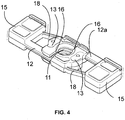
- FIG. 1 to 4 it is shown an embodiment of the holding element 1 intended to adapt to the thickness of a building element to maintain that it encloses at least partially and to ensure the positioning of this element of construction on at least one support structure, the construction element and the support structure being not shown in the figures.
- the holding element 1 according to the present invention comprises a wheel 2 which has an outer shape with a wafer 3, this shape exterior can be round or faceted.
- the holding element 1 according to the present invention also comprises a rod 6 having a thread 10.
- the wheel has a body 2a and the upper face of the body 2a of the wheel 2, that is to say the face which is opposite to that through which will exceed the greater part of the rod 6 to be associated with the wheel 2, wears a cap 4.
- the cap 4 caps this upper face forming the outer portion of the wheel 2, that is to say the part that is not vis-à-vis the element of construction to be clamped by the holding member 1.
- a spacing 5 may remain between the body 2a of the knob 2 and the cap 4.
- the wheel 2 receives the rod 6 by a median recess 9 which passes through it.
- the recess 9 may be extended by gutters 9a surrounding the rod 6 and engaged with the thread 10 of the rod 6, these gutter extending in the height of the cap 4 which has been illustrated without its contour greater than the figure 3 in order to better see his interior.
- the length of the rod 6 which protrudes from the underside of the wheel 2, called the working length, must be adjustable in order to be adapted to the construction element which is at least partially gripped by the holding element 1.
- the rod 6 has a thread 10 and the wheel 2 comprises screwing means 11 cooperating with the pitch of the thread 10 of the portion facing the rod 6 when a portion thereof is housed in the recess 9 of the knob 2.
- the thread 10 of the rod 6 is external.
- the screwing means 11 present in the wheel 2 will be described later.
- the reinforcing piece 7 may have a main portion extending diametrically with respect to the wheel 2 advantageously a edge edge of the wheel 2 at the edge of diametrically opposite edge.
- such a wheel 2 is intended to be associated with a rod 6 passing through at least partially.
- the wheel 2 receives a portion of the rod 6 in its interior removably.
- the median recess 9 of the wheel 2 passes through its upper face to its lower face, the latter being advantageously intended for the introduction of the rod 6. It is possible for an end portion of the rod 6 to come out of the upper face of the wheel 2 carrying the cap 4.
- This end portion or free end portion of the rod 6 advantageously bears no element and may be in the form of a tip, this tip may protrude from the cap 4 of the wheel 2.
- the other end of the rod 6 or rod end end may have a locking form 8 for attachment to a first support structure of any kind, preferably a frame frequently in the form of a rail, but this is not limiting.
- the working length of the rod 6 is defined between the head end portion of the rod 6 after the locking form 8 and the wheel 2.
- the rod 6 is made of plastic, preferably of polypropylene loaded with 30% glass fiber.
- This rod 6 has a thread 10 extending over most of its length.
- Plastic has been chosen as the component of the rod 6, preferably a metal which is conductive, so that the holding element 1 also advantageously serves as a thermal bridge breaker.
- the median recess 9 of the wheel 2 may surround only the portion of the rod 6 housed inside the wheel 2, the screwing means 11 being part of removable fastening means of the rod 6 being against the external threads of the rod 6.
- the screwing means 11 have dimensions and spacings corresponding to the dimensions of the pitch of the thread 10 of the rod 6.
- detachable securing means 12, 12a of the rod 6 relative to the wheel 2 are provided in the wheel 2. These securing means 12, 12a can be largely contained entirely in the wheel 2. These detachable fastening means 12, 12a perform a setting action in engagement with the rod 6 with the wheel 2 without however hindering the rotation of the wheel 2 relative to the rod 6 for adjusting the working length of the rod 6. The wheel 2 can thus be screwed or unscrewed on the rod 6 towards the end of the stem head by decreasing or increasing the working length of the rod 6.
- These securing means 12, 12a comprise screwing means 11 cooperating with the thread 10 of the rod 6 for adjusting the working length of the rod 6 by screwing or unscrewing the wheel 2 around the rod 6.
- the detachable fastening means housed in the wheel 2 comprise two mutually extending plates 12, 12a extending in opposite directions along a diameter of the wheel 2, thus arranged symmetrically radially with respect to the wheel 2.
- the inner end portions 13 of the plates 12, 12a are advantageously nested. at least partially in one another.
- the inner end portion 13 of a plate 12 or 12a may be closer to the outer end of the other plate 12a or 12 than the inner end portion 13 of the other plate 12a or 12 .
- interlocking is to be taken in its broad sense and such interlocking does not mean that there is necessarily a contact between the inner end portions 13 of the two plates 12, 12a but only that an inner end portion 13 of a plate 12 or 12a is closer to the outer end of the other plate 12a or 12 than its own inner end portion and vice versa.
- Notches only one of which is referenced by face, may be provided on at least one face of the inner end portions 13 of the plates 12, 12a for fastening. These notches, when positioned on the faces facing the inner end portions 13, allow guidance in position of the plates 12, 12a relative to each other while allowing an axial displacement of the plates 12, 12a relative to the wheel 2. Notches can also be provided on the opposite faces to each other of each plate 12, 12a, these notches cooperating with forms housed inside the wheel 2 for guiding the plates 12, 12a in the body 2a of the wheel 2.
- the inner end portions 13 of the plates 12, 12a may be superimposed on one another, with one portion 13 resting on the other. Notches may be provided on each of the faces of the portions facing each other, so that there may be a friction force between the two plates 12, 12a making it possible to hold them relative to one another without however prevent radial sliding of the plates 12, 12a relative to each other.
- Each plate 12, 12a has an outer end intended to protrude from the edge of the wafer 3 of the wheel 2 at least in the position of securing the rod 6 relative to the wheel 2.
- the inner end portion 13 of each plate 12, 12a may be located near the plumb of the recess 9 of the wheel 2 when no rod 3 is housed in the recess 9 of the median wheel 2.
- each plate 12, 12a of securing may carry a button 15 to be supported by the installer prior to the attachment of the rod 6 on the wheel 2.
- the buttons 15 of the plates 12, 12a of solidarity may be identical by being mounted head to tail in the knob 2.
- each plate 12, 12a may comprise an internal cavity 16 passing through it in its thickness. This internal cavity 16 is traversed by a portion of the rod 6 during the introduction of the rod 6 into the wheel 2.
- the internal cavities 16 of each plate 12, 12a have walls of complementary shape to partially surround the rod at a distance. 6 when it is pressed into the median recess 9 of the knob 2.
- the internal cavity 16 of each plate 12, 12a is on the other side of the rod 6 than the one on which the end is located. and the button 15 of the same plate 12, 12a, the cavity 16 of each plate 12, 12a being vis-à-vis the cavity 16 of the other plate 12a or 12.
- Each plate 12, 12a is movable between, on the one hand, a first position in which its inner end portion 13 is on the passage of the recess 9 and its outer end protrudes laterally of the wheel 2, this first position being taken when no action by a poser is performed on its outer end and, secondly, a second position in which its inner end portion 13 releases the passage of the recess 9 when an action is exerted on its outer end by the poser.
- the walls of the cavities 16 may be provided with screwing means 11, previously mentioned. These screwing means 11 cooperate with the thread 10 of the portion facing the rod 6 inserted into the recess 9 of the wheel 2, this to effect the adjustment of the working length of the rod 6.
- these screwing means can advantageously be in the form of jaws 11 penetrating the thread 10 of the portion of the rod 6 vis-à-vis. These claws 11 are superimposed and their dimensions and their spacing correspond to the dimensions of the pitch of the thread 10 of the rod 6.
- the jaws 11 can exert a locking action or locking on the rod 6 when they are stressed under the tensile force or compression of the rod 6 while allowing the rotation of the wheel 2 relative to the rod 6 when adjusting the working length of the rod 6, the jaws 11 can move in the thread 10 of the rod 6.
- the claws 11 advantageously extend along an arc of a circle in the associated cavity 16. There may be several claws 11 superimposed on each other.
- the claws 11 are not directly centered on the axis of operation of the buttons 15 of the plates 12, 12a of solidarity but preferably arranged offset with respect to this radial axis.
- the middle of the arc formed by a clutch 11 can be positioned at an angle of 45 ° relative to the axis of operation of the plates 12, 12a of attachment which passes through the middle part of the two buttons Plates 12, 12a.
- the plates 12, 12a of securing have notches on at least one of their faces, such notches can prevent unwanted retraction of the jaws 11 out of contact with the rod 6 during a force exerted on the rod 6.
- each plate 12, 12a for securing is associated with a return means 18 in position in which its button 15 projects outside the edge of the wafer 3 of the wheel 2, that is to say the first previously mentioned position.
- This allows an automatic maintenance of the portion of the rod 6 vis-à-vis the recess 9 with automatic return of the inner end portions 13, preferably by the inner walls of the cavities 16 against the rod 6.
- the return means 18 in position can be carried by each plate 12, 12a of securing. In a non-limiting embodiment, it is the second plate 12, 12a which carries a return means 18 in position acting on the first plate 12, 12a and vice versa.
- the two plates 12, 12a of solidarity to bring the other plate 12, 12a associated in the position so that its button 15 protrudes from the edge of the slice 3 of the wheel 2.
- the position return means may be in the form of an elastic blade 18 carried by the middle portion of a plate 12, 12a located near the inner end portion 13 of the another plate 12a, 12 and performing its restoring action on the innermost face of this inner end portion 13 of the other plate 12, 12a and vice versa.
- each plate 12, 12a can also carry its own return means 18 in position and thus individually perform its recall in position.
- the choice of materials for the return means 18 also contributes a lot to the results. It is thus preferred to use a plastic material with high elastic and memory properties, especially for the return means 18.
- the installer to adjust the working length of the rod 6 protruding from the wheel 2 by rotation of the wheel of the holding element 1.
- the rotation of the wheel 2 makes it possible to reduce or to increase the working length of the rod 6 protruding from the wheel 2 due to the cooperation of the thread 10 present on the rod 6 relative to the screwing means, advantageously jaw 11, that have the securing means 12, 12a .
- This has the great advantage of simply adjusting the working length of the rod 6 protruding from the wheel 2 and therefore to adapt to the thickness of the building element to maintain.
- the present invention relates to a method of removably mounting a rod 6 provided with a thread 10 in a wheel 2 and adjusting the wheel 2 relative to the rod 6 to obtain a desired working length of the rod 6 in a holding element 1 as previously described.
- the method comprises the step of action of a setter to render inoperative the securing means 12, 12a of the rod 6 with the wheel 2 followed by the introduction of a portion of the rod 6 in the wheel 2. Then , it is proceeded to the cessation of the action of the setter, which makes again operating the securing means 12, 12a of the rod 6 with the wheel 2.
- the screwing means 11 of the securing means 12, 12a then cooperate with the thread 10 of the rod 6 for adjusting the working length of the rod 6. The installer then simply makes the rotation of the wheel 2 until the desired working length of the rod 6.
- the wheel 2 and the end of the rod 6 furthest from the wheel 2 may respectively carry securing means 17, 5 with a respective support structure of the construction element to maintain.
- These support structures may, for example, be in the respective form of a framework, frequently metal, preferably a rail also called fur, including type 45 and 47 furring.
- This frame in the form of a rail may have a U-shaped with the free end of the branches of the U curved at 90 ° to the inside of the U with respect to the branches, commonly called wing return.
- the end of the rod 6 farthest from the wheel 2 may have a spacer 8 as blocking form previously mentioned.
- the spacer 8 enters the rail also called fur and can be provided with forms of quick attachment, for example by having a groove 17 receiving by clipping the curved free end of the branches of the rail.
- this rail having a shape similar to the rail cooperating with the other end of the rod 6, by penetrating the curved free end of the branches of the rail between the cap 4 of the wheel 2 and the body 2a of the wheel 2, a spacing 5 remaining between the cap 4 and the body 2a.
- a wheel 2 according to the present invention advantageously combines two functions, namely a function of adjusting the working length of the rod 6 and a function of attachment to a support structure.
- the present invention therefore also relates to a construction element interposed between first and second support structures, this element being held between the support structures by at least one holding element as previously described.
Landscapes
- Engineering & Computer Science (AREA)
- Architecture (AREA)
- Civil Engineering (AREA)
- Structural Engineering (AREA)
- Mutual Connection Of Rods And Tubes (AREA)
- Clamps And Clips (AREA)
- Connection Of Plates (AREA)
Claims (14)
- Halteelement (1) aufweisend eine Stange (6), ein Abschnitt deren Länge, Arbeitslänge genannt, der Dicke eines von dem Element (1) zu haltenden Konstruktionselements entspricht, wobei:die Stange (6) ein Gewinde (10) aufweist,das Halteelement (1) einen im Wesentlichen kreisförmigen Einstellknopf (2) aufweist,der die Stange (6) auf lösbare Weise in einer zentralen Aussparung (9) aufnimmt,der Einstellknopf (2) mit Verbindungseinrichtungen (12, 12a) zum Verbinden mit der Stange (6) versehen ist, die Schraubeinrichtungen (11) aufweisen, die mit dem Gewinde (10) der Stange (6) zusammenwirken, um durch Drehen des Einstellknopfs (2) um die Stange (6) in Einschraubrichtung oder Ausschraubrichtung die Arbeitslänge der Stange (6) anzupassen,wobei das Halteelement dadurch gekennzeichnet ist, dassdie Verbindungseinrichtungen zwei Verbindungsplatten (12, 12a) aufweisen, die in dem Einstellknopf (2) des Halteelements untergebracht sind und sich in zueinander entgegengesetzter Richtung gemäß einer Verschiebungsachse, die einem Durchmesser des Einstellknopfs (2) folgt, erstrecken, wobei jede Platte (12, 12a) bewegbar ist zwischen einerseits einer ersten Position, in welcher ihr innerer Endabschnitt (13) sich über dem Durchlass der Aussparung (9) befindet und ihr äußeres Ende seitlich des Einstellknopfs (2) vorragt, wobei diese erste Position eingenommen ist, wenn von einem Benutzer keine Aktion auf ihr äußeres Ende ausgeübt wird, und andererseits einer zweiten Position, in welcher ihr innerer Endabschnitt (13) den Durchlass der Aussparung (9) freigibt, wenn von dem Benutzer eine Aktion auf ihr äußeres Ende ausgeübt wird.
- Halteelement (1) nach dem vorstehenden Anspruch, wobei das äußere Ende jeder Verbindungsplatte (12, 12a) einen Knopf (15) aufweist, der von dem Benutzer betätigbar ist, um die Platte (12, 12a) in ihre zweite Position zu stellen.
- Halteelement (1) nach einem der zwei vorstehenden Ansprüche, wobei jede Verbindungsplatte (12, 12a) von einer Positionsrückstelleinrichtung (18) in die erste Position zurückgestellt wird.
- Halteelement (1) nach dem vorstehenden Anspruch, wobei die Positionsrückstelleinrichtung (18) der einen Platte (12, 12a) von der anderen Platte (12, 12a) und umgekehrt getragen wird, wobei diese Rückstelleinrichtung in Form eines Rückstellblättchens (18) ist.
- Halteelement (1) nach einem der vier vorstehenden Ansprüche, wobei der innere Endabschnitt (13) jeder Platte (12, 12a) die Schraubeinrichtungen (11) trägt, die mit dem Gewinde (10) des gegenüberliegenden Abschnitts der in die Aussparung (9) des Einstellknopfs (2) eingeführten Stange (6) zusammenwirken.
- Halteelement (1) nach dem vorstehenden Anspruch, wobei die inneren Endabschnitte (13) der Verbindungsplatten (12, 12a) Hohlräume (16) aufweisen, die die Schraubeinrichtungen (11) an ihrer Innenwand tragen und den in der Aussparung (9) gegenüber angeordneten Abschnitt der Stange (6) mindestens teilweise umgeben.
- Halteelement (1) nach einem der Ansprüche 1 bis 6, wobei die Schraubeinrichtungen in Form von übereinander liegenden Klauen (11) sind, deren Abmessungen und Abstände den Abmessungen der Steigung des Gewindes (10) der Stange (6) entsprechen.
- Halteelement (1) nach dem vorstehenden Anspruch, wobei die Klauen (11) sich in Form von Kreisbögen erstrecken, die übereinander angeordnet sind und bezüglich der Verschiebungsachse der Verbindungsplatten (12, 12a) versetzt angeordnet sind.
- Halteelement (1) nach dem vorstehenden Anspruch, wobei die Mitte des Kreisbogens, der einer jeweiligen Klaue zugeordnet ist, um 45° bezüglich der Verschiebungsachse der Verbindungsplatten (12, 12a) versetzt angeordnet ist.
- Halteelement (1) nach einem der vorstehenden Ansprüche, wobei das von dem Einstellknopf (2) entfernt gelegene Ende der Stange (6) Klemmeinrichtungen (8, 17) zum Klemmeingriff mit einer ersten Trägerstruktur aufweist.
- Halteelement (1) nach dem vorstehenden Anspruch, wobei die Klemmeinrichtungen (8, 17) aus einer Querstrebe (8) gebildet sind, die in die erste Trägerstruktur eindringt, wobei die Querstrebe (8) eine Rille (17) aufweist, die einen Abschnitt der ersten Trägerstruktur durch Klemmeingriff aufnimmt.
- Halteelement (1) nach einem der vorstehenden Ansprüche, wobei der Einstellknopf (2) einen Körper (2a) aufweist, in welchem die die Stange (6) mit dem Einstellknopf (2) verbindenden Verbindungsplatten (12, 12a) untergebracht sind, wobei der Körper (2a) an seiner bezüglich dem Abschnitt der Länge der Stange (6), der sogenannten Arbeitslänge, entgegengesetzten Fläche mit einer Kappe (4) bedeckt ist, wobei zwischen dem Körper (2a) und der Kappe (4) ein Freiraum (5) vorgesehen ist und der Freiraum (5) zum Klemmeingriff mit einer zweiten Trägerstruktur dient.
- Verfahren zum lösbaren Anbringen einer mit einem Gewinde (10) versehenen Stange (6) in einem Einstellknopf (2) und zum Anpassen des Einstellknopfs (2) bezüglich der Stange (6) zur Bereitstellung einer gewünschten Arbeitslänge der Stange (6) in einem Halteelement (1) nach einem der vorstehenden Ansprüche, wobei das Verfahren die folgenden Schritte aufweist:- von einem Benutzer ausgeübte Aktion auf das äußere Ende der Verbindungsplatten (12, 12a), um sie als Einrichtungen zum Verbinden der Stange (6) mit dem Einstellknopf (2) unwirksam zu machen,- Einführen eines Abschnitts der Stange (6) in den Einstellknopf (2),- Beenden der Aktion des Benutzers, die die Verbindungsplatten (12, 12a) als Einrichtungen zum Verbinden der Stange (6) mit dem Einstellknopf (2) wirksam macht, wobei zum Anpassen der Arbeitslänge der Stange (6) die Schraubeinrichtungen (11) der Verbindungsplatten (12, 12a) mit dem Gewinde (10) der Stange (6) zusammenwirken,- Drehen des Einstellknopfs (2), bis die gewünschte Arbeitslänge der Stange (6) erreicht ist.
- Zwischen einer ersten und zweiten Trägerstruktur angeordnetes Konstruktionselement, dadurch gekennzeichnet, dass es von mindestens einem Halteelement (1) nach einem der Ansprüche 1 bis 12 zwischen den Trägerstrukturen gehalten wird.
Priority Applications (1)
| Application Number | Priority Date | Filing Date | Title |
|---|---|---|---|
| PL15719499T PL3126591T3 (pl) | 2014-03-26 | 2015-03-25 | Element mocujący utworzony z pokrętła i z pręta z regulacją długości pręta wystającego z pokrętła |
Applications Claiming Priority (2)
| Application Number | Priority Date | Filing Date | Title |
|---|---|---|---|
| FR1400751A FR3019200B1 (fr) | 2014-03-26 | 2014-03-26 | Element de maintien constitue d'une molette et d'une tige avec reglage de la longueur de la tige depassant de la molette |
| PCT/FR2015/000066 WO2015144998A1 (fr) | 2014-03-26 | 2015-03-25 | Élément de maintien constitué d'une molette et d'une tige avec réglage de la longueur de la tige dépassant de la molette |
Publications (2)
| Publication Number | Publication Date |
|---|---|
| EP3126591A1 EP3126591A1 (de) | 2017-02-08 |
| EP3126591B1 true EP3126591B1 (de) | 2018-05-16 |
Family
ID=50933254
Family Applications (1)
| Application Number | Title | Priority Date | Filing Date |
|---|---|---|---|
| EP15719499.4A Active EP3126591B1 (de) | 2014-03-26 | 2015-03-25 | Halteelement aus einem einstellknopf und einer stange mit einstellung der länge der stange über den einstellknopf hinaus |
Country Status (5)
| Country | Link |
|---|---|
| EP (1) | EP3126591B1 (de) |
| ES (1) | ES2682085T3 (de) |
| FR (1) | FR3019200B1 (de) |
| PL (1) | PL3126591T3 (de) |
| WO (1) | WO2015144998A1 (de) |
Families Citing this family (3)
| Publication number | Priority date | Publication date | Assignee | Title |
|---|---|---|---|---|
| FR3050747B1 (fr) * | 2016-04-28 | 2020-09-18 | Plastiforms | Dispositif d'entretoisement pour parement mural. |
| FR3110189B1 (fr) * | 2020-05-14 | 2022-06-03 | Thierry Azerad | Dispositif d’entretoisement, doublage d’une paroi incluant un film traversé par la tige de tels dispositifs, et procédé de montage d’un élément stoppeur destiné à supporter un film dans un doublage de paroi |
| FR3120101B1 (fr) | 2021-02-24 | 2023-03-03 | Zifort | Dispositif de fixation de panneaux à distance d’une structure |
Family Cites Families (2)
| Publication number | Priority date | Publication date | Assignee | Title |
|---|---|---|---|---|
| FR2826390B1 (fr) * | 2001-06-21 | 2003-10-03 | Pflerderer | Dispositif de fixation pour un revetement isolant de batiment |
| FR2930006B1 (fr) * | 2008-12-16 | 2010-03-19 | Thierry Azerad | Dispositif de fixation et de reglage rapide d'ossatures metalliques recevant un isolant |
-
2014
- 2014-03-26 FR FR1400751A patent/FR3019200B1/fr active Active
-
2015
- 2015-03-25 ES ES15719499.4T patent/ES2682085T3/es active Active
- 2015-03-25 EP EP15719499.4A patent/EP3126591B1/de active Active
- 2015-03-25 WO PCT/FR2015/000066 patent/WO2015144998A1/fr active Application Filing
- 2015-03-25 PL PL15719499T patent/PL3126591T3/pl unknown
Non-Patent Citations (1)
| Title |
|---|
| None * |
Also Published As
| Publication number | Publication date |
|---|---|
| EP3126591A1 (de) | 2017-02-08 |
| FR3019200B1 (fr) | 2017-10-13 |
| ES2682085T3 (es) | 2018-09-18 |
| FR3019200A1 (fr) | 2015-10-02 |
| WO2015144998A1 (fr) | 2015-10-01 |
| PL3126591T3 (pl) | 2018-11-30 |
Similar Documents
| Publication | Publication Date | Title |
|---|---|---|
| EP3126591B1 (de) | Halteelement aus einem einstellknopf und einer stange mit einstellung der länge der stange über den einstellknopf hinaus | |
| EP2542797B1 (de) | Verbessertes stromabsorptionselement und vorspannungsflansch dafür | |
| EP2476922B1 (de) | Vorrichtung zum Befestigen einer Dämmverkleidung eines Gebäudes | |
| EP3561608B1 (de) | Befestigungsleiste eines armbands an einer armbanduhr, die mit zwei einziehbaren drehzapfen ausgestattet ist | |
| EP2664731A1 (de) | Verfahren und Vorrichtung zum Befestigen eines Verkleidungsschilds mit genuteter Kante auf einem Halteprofil, und Gesamtanordnung, die aus mindestens einer Befestigungsvorrichtung vom genannten Typ besteht | |
| EP2785927B1 (de) | Abstandsvorrichtung für eine vorrichtung zum befestigen eines objekts an einer wand mit einer isolierschicht | |
| EP1712434A1 (de) | Einziehbarer Stossdämpferanschlag für ein Kraftfahrzeug | |
| EP3693624B1 (de) | Schnellverschlussglied | |
| EP2889439A1 (de) | Verankerungsvorrichtung mit Verstrebungen für kreisförmige Bewehrungen | |
| EP2980421B1 (de) | Befestigungsvorrichtung eines teils auf einer halterung mit kompensierung des abstands zwischen dem teil und der halterung, regulierelement und reguliereinheit einer solchen vorrichtung | |
| EP2700064B1 (de) | Vorrichtung zum aufhängen einer markise | |
| CA3078766A1 (fr) | Outillage pour la realisation in situ d'un mur sandwich et procede en faisant application | |
| EP3563067B1 (de) | Bändelungsvorrichtung | |
| EP2839929B1 (de) | Einspannvorrichtung vom Typ Schraubzwinge | |
| EP2377742A1 (de) | Verstellmechanismus für eine Lenksäule eines Kraftfahrzeugs | |
| WO2015155425A1 (fr) | Dispositif d'adaptation destiné à recevoir l'extrémité d'une tige formant élément de maintien pour un élément de construction enserré par l'élément de maintien | |
| FR2891298A1 (fr) | Arret de volet comportant un blocage reglable | |
| EP3067169B1 (de) | Messer mit klappklinge, das mit einem verbesserten blockierring ausgestattet ist | |
| EP3261803B1 (de) | Nietvorrichtung für präzisionsanordnung | |
| EP3026767B1 (de) | Verankerungsverfahren zum verankern eines kabels mit einem bestimmten durchmesser in einer halterung | |
| EP2690245A1 (de) | Einlauftrichter und Führungsschiene für Rollladen | |
| EP3434536B1 (de) | Befestigungsvorrichtung für ein gestängesystem zur betätigung von scheibenwischern | |
| FR3080875A1 (fr) | Dispositif de maintien temporaire d'elements de construction et procede d'utilisation d'un tel dispositif | |
| FR3052479A1 (fr) | Fenetre comprenant un dispositif de mouflage | |
| CH711980A2 (fr) | Dispositif de maintien et de relâchement de tension axiale d'une tige, application et procédés de mis en œuvre d'un tel dispositif. |
Legal Events
| Date | Code | Title | Description |
|---|---|---|---|
| STAA | Information on the status of an ep patent application or granted ep patent |
Free format text: STATUS: THE INTERNATIONAL PUBLICATION HAS BEEN MADE |
|
| PUAI | Public reference made under article 153(3) epc to a published international application that has entered the european phase |
Free format text: ORIGINAL CODE: 0009012 |
|
| STAA | Information on the status of an ep patent application or granted ep patent |
Free format text: STATUS: REQUEST FOR EXAMINATION WAS MADE |
|
| 17P | Request for examination filed |
Effective date: 20161020 |
|
| AK | Designated contracting states |
Kind code of ref document: A1 Designated state(s): AL AT BE BG CH CY CZ DE DK EE ES FI FR GB GR HR HU IE IS IT LI LT LU LV MC MK MT NL NO PL PT RO RS SE SI SK SM TR |
|
| AX | Request for extension of the european patent |
Extension state: BA ME |
|
| DAV | Request for validation of the european patent (deleted) | ||
| DAX | Request for extension of the european patent (deleted) | ||
| GRAP | Despatch of communication of intention to grant a patent |
Free format text: ORIGINAL CODE: EPIDOSNIGR1 |
|
| STAA | Information on the status of an ep patent application or granted ep patent |
Free format text: STATUS: GRANT OF PATENT IS INTENDED |
|
| RIC1 | Information provided on ipc code assigned before grant |
Ipc: F16B 5/02 20060101ALN20171120BHEP Ipc: E04F 13/08 20060101AFI20171120BHEP Ipc: F16B 37/08 20060101ALI20171120BHEP |
|
| INTG | Intention to grant announced |
Effective date: 20171205 |
|
| GRAS | Grant fee paid |
Free format text: ORIGINAL CODE: EPIDOSNIGR3 |
|
| GRAA | (expected) grant |
Free format text: ORIGINAL CODE: 0009210 |
|
| STAA | Information on the status of an ep patent application or granted ep patent |
Free format text: STATUS: THE PATENT HAS BEEN GRANTED |
|
| AK | Designated contracting states |
Kind code of ref document: B1 Designated state(s): AL AT BE BG CH CY CZ DE DK EE ES FI FR GB GR HR HU IE IS IT LI LT LU LV MC MK MT NL NO PL PT RO RS SE SI SK SM TR |
|
| REG | Reference to a national code |
Ref country code: GB Ref legal event code: FG4D Free format text: NOT ENGLISH |
|
| REG | Reference to a national code |
Ref country code: CH Ref legal event code: EP |
|
| REG | Reference to a national code |
Ref country code: DE Ref legal event code: R096 Ref document number: 602015011193 Country of ref document: DE |
|
| REG | Reference to a national code |
Ref country code: IE Ref legal event code: FG4D Free format text: LANGUAGE OF EP DOCUMENT: FRENCH |
|
| REG | Reference to a national code |
Ref country code: AT Ref legal event code: REF Ref document number: 999708 Country of ref document: AT Kind code of ref document: T Effective date: 20180615 |
|
| REG | Reference to a national code |
Ref country code: CH Ref legal event code: PK Free format text: RECTIFICATIONS |
|
| RAP2 | Party data changed (patent owner data changed or rights of a patent transferred) |
Owner name: AZERAD, THIERRY |
|
| RIN2 | Information on inventor provided after grant (corrected) |
Inventor name: AZERAD, THIERRY |
|
| REG | Reference to a national code |
Ref country code: ES Ref legal event code: FG2A Ref document number: 2682085 Country of ref document: ES Kind code of ref document: T3 Effective date: 20180918 |
|
| REG | Reference to a national code |
Ref country code: NL Ref legal event code: MP Effective date: 20180516 |
|
| REG | Reference to a national code |
Ref country code: LT Ref legal event code: MG4D |
|
| PG25 | Lapsed in a contracting state [announced via postgrant information from national office to epo] |
Ref country code: SE Free format text: LAPSE BECAUSE OF FAILURE TO SUBMIT A TRANSLATION OF THE DESCRIPTION OR TO PAY THE FEE WITHIN THE PRESCRIBED TIME-LIMIT Effective date: 20180516 Ref country code: LT Free format text: LAPSE BECAUSE OF FAILURE TO SUBMIT A TRANSLATION OF THE DESCRIPTION OR TO PAY THE FEE WITHIN THE PRESCRIBED TIME-LIMIT Effective date: 20180516 Ref country code: FI Free format text: LAPSE BECAUSE OF FAILURE TO SUBMIT A TRANSLATION OF THE DESCRIPTION OR TO PAY THE FEE WITHIN THE PRESCRIBED TIME-LIMIT Effective date: 20180516 Ref country code: NO Free format text: LAPSE BECAUSE OF FAILURE TO SUBMIT A TRANSLATION OF THE DESCRIPTION OR TO PAY THE FEE WITHIN THE PRESCRIBED TIME-LIMIT Effective date: 20180816 Ref country code: BG Free format text: LAPSE BECAUSE OF FAILURE TO SUBMIT A TRANSLATION OF THE DESCRIPTION OR TO PAY THE FEE WITHIN THE PRESCRIBED TIME-LIMIT Effective date: 20180816 |
|
| PG25 | Lapsed in a contracting state [announced via postgrant information from national office to epo] |
Ref country code: GR Free format text: LAPSE BECAUSE OF FAILURE TO SUBMIT A TRANSLATION OF THE DESCRIPTION OR TO PAY THE FEE WITHIN THE PRESCRIBED TIME-LIMIT Effective date: 20180817 Ref country code: RS Free format text: LAPSE BECAUSE OF FAILURE TO SUBMIT A TRANSLATION OF THE DESCRIPTION OR TO PAY THE FEE WITHIN THE PRESCRIBED TIME-LIMIT Effective date: 20180516 Ref country code: NL Free format text: LAPSE BECAUSE OF FAILURE TO SUBMIT A TRANSLATION OF THE DESCRIPTION OR TO PAY THE FEE WITHIN THE PRESCRIBED TIME-LIMIT Effective date: 20180516 Ref country code: LV Free format text: LAPSE BECAUSE OF FAILURE TO SUBMIT A TRANSLATION OF THE DESCRIPTION OR TO PAY THE FEE WITHIN THE PRESCRIBED TIME-LIMIT Effective date: 20180516 Ref country code: HR Free format text: LAPSE BECAUSE OF FAILURE TO SUBMIT A TRANSLATION OF THE DESCRIPTION OR TO PAY THE FEE WITHIN THE PRESCRIBED TIME-LIMIT Effective date: 20180516 |
|
| REG | Reference to a national code |
Ref country code: AT Ref legal event code: MK05 Ref document number: 999708 Country of ref document: AT Kind code of ref document: T Effective date: 20180516 |
|
| PG25 | Lapsed in a contracting state [announced via postgrant information from national office to epo] |
Ref country code: CZ Free format text: LAPSE BECAUSE OF FAILURE TO SUBMIT A TRANSLATION OF THE DESCRIPTION OR TO PAY THE FEE WITHIN THE PRESCRIBED TIME-LIMIT Effective date: 20180516 Ref country code: SK Free format text: LAPSE BECAUSE OF FAILURE TO SUBMIT A TRANSLATION OF THE DESCRIPTION OR TO PAY THE FEE WITHIN THE PRESCRIBED TIME-LIMIT Effective date: 20180516 Ref country code: EE Free format text: LAPSE BECAUSE OF FAILURE TO SUBMIT A TRANSLATION OF THE DESCRIPTION OR TO PAY THE FEE WITHIN THE PRESCRIBED TIME-LIMIT Effective date: 20180516 Ref country code: AT Free format text: LAPSE BECAUSE OF FAILURE TO SUBMIT A TRANSLATION OF THE DESCRIPTION OR TO PAY THE FEE WITHIN THE PRESCRIBED TIME-LIMIT Effective date: 20180516 Ref country code: DK Free format text: LAPSE BECAUSE OF FAILURE TO SUBMIT A TRANSLATION OF THE DESCRIPTION OR TO PAY THE FEE WITHIN THE PRESCRIBED TIME-LIMIT Effective date: 20180516 Ref country code: RO Free format text: LAPSE BECAUSE OF FAILURE TO SUBMIT A TRANSLATION OF THE DESCRIPTION OR TO PAY THE FEE WITHIN THE PRESCRIBED TIME-LIMIT Effective date: 20180516 |
|
| REG | Reference to a national code |
Ref country code: DE Ref legal event code: R097 Ref document number: 602015011193 Country of ref document: DE |
|
| PG25 | Lapsed in a contracting state [announced via postgrant information from national office to epo] |
Ref country code: SM Free format text: LAPSE BECAUSE OF FAILURE TO SUBMIT A TRANSLATION OF THE DESCRIPTION OR TO PAY THE FEE WITHIN THE PRESCRIBED TIME-LIMIT Effective date: 20180516 |
|
| PLBE | No opposition filed within time limit |
Free format text: ORIGINAL CODE: 0009261 |
|
| STAA | Information on the status of an ep patent application or granted ep patent |
Free format text: STATUS: NO OPPOSITION FILED WITHIN TIME LIMIT |
|
| 26N | No opposition filed |
Effective date: 20190219 |
|
| PG25 | Lapsed in a contracting state [announced via postgrant information from national office to epo] |
Ref country code: SI Free format text: LAPSE BECAUSE OF FAILURE TO SUBMIT A TRANSLATION OF THE DESCRIPTION OR TO PAY THE FEE WITHIN THE PRESCRIBED TIME-LIMIT Effective date: 20180516 |
|
| PG25 | Lapsed in a contracting state [announced via postgrant information from national office to epo] |
Ref country code: MC Free format text: LAPSE BECAUSE OF FAILURE TO SUBMIT A TRANSLATION OF THE DESCRIPTION OR TO PAY THE FEE WITHIN THE PRESCRIBED TIME-LIMIT Effective date: 20180516 |
|
| REG | Reference to a national code |
Ref country code: CH Ref legal event code: PL |
|
| PG25 | Lapsed in a contracting state [announced via postgrant information from national office to epo] |
Ref country code: LU Free format text: LAPSE BECAUSE OF NON-PAYMENT OF DUE FEES Effective date: 20190325 Ref country code: AL Free format text: LAPSE BECAUSE OF FAILURE TO SUBMIT A TRANSLATION OF THE DESCRIPTION OR TO PAY THE FEE WITHIN THE PRESCRIBED TIME-LIMIT Effective date: 20180516 |
|
| PG25 | Lapsed in a contracting state [announced via postgrant information from national office to epo] |
Ref country code: IE Free format text: LAPSE BECAUSE OF NON-PAYMENT OF DUE FEES Effective date: 20190325 Ref country code: LI Free format text: LAPSE BECAUSE OF NON-PAYMENT OF DUE FEES Effective date: 20190331 Ref country code: CH Free format text: LAPSE BECAUSE OF NON-PAYMENT OF DUE FEES Effective date: 20190331 |
|
| PG25 | Lapsed in a contracting state [announced via postgrant information from national office to epo] |
Ref country code: TR Free format text: LAPSE BECAUSE OF FAILURE TO SUBMIT A TRANSLATION OF THE DESCRIPTION OR TO PAY THE FEE WITHIN THE PRESCRIBED TIME-LIMIT Effective date: 20180516 |
|
| PG25 | Lapsed in a contracting state [announced via postgrant information from national office to epo] |
Ref country code: PT Free format text: LAPSE BECAUSE OF FAILURE TO SUBMIT A TRANSLATION OF THE DESCRIPTION OR TO PAY THE FEE WITHIN THE PRESCRIBED TIME-LIMIT Effective date: 20180917 Ref country code: MT Free format text: LAPSE BECAUSE OF FAILURE TO SUBMIT A TRANSLATION OF THE DESCRIPTION OR TO PAY THE FEE WITHIN THE PRESCRIBED TIME-LIMIT Effective date: 20180516 |
|
| PG25 | Lapsed in a contracting state [announced via postgrant information from national office to epo] |
Ref country code: CY Free format text: LAPSE BECAUSE OF FAILURE TO SUBMIT A TRANSLATION OF THE DESCRIPTION OR TO PAY THE FEE WITHIN THE PRESCRIBED TIME-LIMIT Effective date: 20180516 |
|
| PG25 | Lapsed in a contracting state [announced via postgrant information from national office to epo] |
Ref country code: IS Free format text: LAPSE BECAUSE OF FAILURE TO SUBMIT A TRANSLATION OF THE DESCRIPTION OR TO PAY THE FEE WITHIN THE PRESCRIBED TIME-LIMIT Effective date: 20180916 |
|
| PG25 | Lapsed in a contracting state [announced via postgrant information from national office to epo] |
Ref country code: HU Free format text: LAPSE BECAUSE OF FAILURE TO SUBMIT A TRANSLATION OF THE DESCRIPTION OR TO PAY THE FEE WITHIN THE PRESCRIBED TIME-LIMIT; INVALID AB INITIO Effective date: 20150325 |
|
| PG25 | Lapsed in a contracting state [announced via postgrant information from national office to epo] |
Ref country code: MK Free format text: LAPSE BECAUSE OF FAILURE TO SUBMIT A TRANSLATION OF THE DESCRIPTION OR TO PAY THE FEE WITHIN THE PRESCRIBED TIME-LIMIT Effective date: 20180516 |
|
| PGFP | Annual fee paid to national office [announced via postgrant information from national office to epo] |
Ref country code: FR Payment date: 20230118 Year of fee payment: 9 |
|
| PGFP | Annual fee paid to national office [announced via postgrant information from national office to epo] |
Ref country code: PL Payment date: 20230228 Year of fee payment: 9 Ref country code: IT Payment date: 20230308 Year of fee payment: 9 Ref country code: BE Payment date: 20230316 Year of fee payment: 9 |
|
| P01 | Opt-out of the competence of the unified patent court (upc) registered |
Effective date: 20230512 |
|
| PGFP | Annual fee paid to national office [announced via postgrant information from national office to epo] |
Ref country code: ES Payment date: 20230405 Year of fee payment: 9 |
|
| PGFP | Annual fee paid to national office [announced via postgrant information from national office to epo] |
Ref country code: DE Payment date: 20240307 Year of fee payment: 10 Ref country code: GB Payment date: 20240325 Year of fee payment: 10 |