EP3125831B1 - Delivery and deployment systems for bifurcated stent grafts - Google Patents
Delivery and deployment systems for bifurcated stent grafts Download PDFInfo
- Publication number
- EP3125831B1 EP3125831B1 EP15721904.9A EP15721904A EP3125831B1 EP 3125831 B1 EP3125831 B1 EP 3125831B1 EP 15721904 A EP15721904 A EP 15721904A EP 3125831 B1 EP3125831 B1 EP 3125831B1
- Authority
- EP
- European Patent Office
- Prior art keywords
- core member
- leg
- stent graft
- section
- diameter
- Prior art date
- Legal status (The legal status is an assumption and is not a legal conclusion. Google has not performed a legal analysis and makes no representation as to the accuracy of the status listed.)
- Active
Links
- 238000006073 displacement reaction Methods 0.000 description 4
- 238000012986 modification Methods 0.000 description 2
- 230000004048 modification Effects 0.000 description 2
- 230000000717 retained effect Effects 0.000 description 2
- 208000025494 Aortic disease Diseases 0.000 description 1
- 230000007246 mechanism Effects 0.000 description 1
- 238000000034 method Methods 0.000 description 1
- 230000001737 promoting effect Effects 0.000 description 1
- 230000002792 vascular Effects 0.000 description 1
Images


Classifications
-
- A—HUMAN NECESSITIES
- A61—MEDICAL OR VETERINARY SCIENCE; HYGIENE
- A61F—FILTERS IMPLANTABLE INTO BLOOD VESSELS; PROSTHESES; DEVICES PROVIDING PATENCY TO, OR PREVENTING COLLAPSING OF, TUBULAR STRUCTURES OF THE BODY, e.g. STENTS; ORTHOPAEDIC, NURSING OR CONTRACEPTIVE DEVICES; FOMENTATION; TREATMENT OR PROTECTION OF EYES OR EARS; BANDAGES, DRESSINGS OR ABSORBENT PADS; FIRST-AID KITS
- A61F2/00—Filters implantable into blood vessels; Prostheses, i.e. artificial substitutes or replacements for parts of the body; Appliances for connecting them with the body; Devices providing patency to, or preventing collapsing of, tubular structures of the body, e.g. stents
- A61F2/95—Instruments specially adapted for placement or removal of stents or stent-grafts
- A61F2/954—Instruments specially adapted for placement or removal of stents or stent-grafts for placing stents or stent-grafts in a bifurcation
-
- A—HUMAN NECESSITIES
- A61—MEDICAL OR VETERINARY SCIENCE; HYGIENE
- A61F—FILTERS IMPLANTABLE INTO BLOOD VESSELS; PROSTHESES; DEVICES PROVIDING PATENCY TO, OR PREVENTING COLLAPSING OF, TUBULAR STRUCTURES OF THE BODY, e.g. STENTS; ORTHOPAEDIC, NURSING OR CONTRACEPTIVE DEVICES; FOMENTATION; TREATMENT OR PROTECTION OF EYES OR EARS; BANDAGES, DRESSINGS OR ABSORBENT PADS; FIRST-AID KITS
- A61F2/00—Filters implantable into blood vessels; Prostheses, i.e. artificial substitutes or replacements for parts of the body; Appliances for connecting them with the body; Devices providing patency to, or preventing collapsing of, tubular structures of the body, e.g. stents
- A61F2/02—Prostheses implantable into the body
- A61F2/04—Hollow or tubular parts of organs, e.g. bladders, tracheae, bronchi or bile ducts
- A61F2/06—Blood vessels
- A61F2/07—Stent-grafts
-
- A—HUMAN NECESSITIES
- A61—MEDICAL OR VETERINARY SCIENCE; HYGIENE
- A61F—FILTERS IMPLANTABLE INTO BLOOD VESSELS; PROSTHESES; DEVICES PROVIDING PATENCY TO, OR PREVENTING COLLAPSING OF, TUBULAR STRUCTURES OF THE BODY, e.g. STENTS; ORTHOPAEDIC, NURSING OR CONTRACEPTIVE DEVICES; FOMENTATION; TREATMENT OR PROTECTION OF EYES OR EARS; BANDAGES, DRESSINGS OR ABSORBENT PADS; FIRST-AID KITS
- A61F2/00—Filters implantable into blood vessels; Prostheses, i.e. artificial substitutes or replacements for parts of the body; Appliances for connecting them with the body; Devices providing patency to, or preventing collapsing of, tubular structures of the body, e.g. stents
- A61F2/02—Prostheses implantable into the body
- A61F2/04—Hollow or tubular parts of organs, e.g. bladders, tracheae, bronchi or bile ducts
- A61F2/06—Blood vessels
- A61F2002/065—Y-shaped blood vessels
Definitions
- the present disclosure relates to medical device deployment systems for bifurcated stent grafts.
- US 2007/0050015 A1 discloses a bifurcated endoluminal device compressed for endoluminal placement in an outer sheath and mounted on guidewire tube. An inner sheath terminates just proximal of the proximal end of second branch portion and pusher element is disposed just proximal of first branch portion.
- WO 2007/025101 A2 discloses an endoluminal device adapted to be deployed in a branched body lumen provided by intraluminal delivery from an access location remote from the location at which the device is to be deployed, i.e. by introduction through one of the branches of the branched body lumen.
- the device comprises an unbranched portion, a first branch portion and second branch portion in communication with the unbranched portion, and a distortion element removeably connected to the first branch portion for manipulating the geometry of the second branch portion.
- the distortion element extends along the first branch portion and back to the access location.
- a system for endoluminal delivery of a medical device includes a bifurcated stent graft comprising a trunk, a first leg and a second leg, wherein the first leg is longer than the second leg; a sheath having a tubular wall having a cylindrical inner surface defining a lumen for receiving the stent graft therein to constrain the stent graft toward a delivery configuration suitable for endoluminal delivery; and a generally cylindrical core member extending through the lumen, the core member having a first section having a first diameter, a second section having a second diameter smaller than the first diameter, and a third section having a third diameter smaller than the second diameter, the core having an annular first end surface between the first and second sections, and an annular second end surface between the second and third sections, wherein the first and second ends surfaces of the core member engage respective axially spaced apart portions of the stent graft during axial displacement of the sheath with respect to the core member.
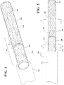
- a delivery system for delivery of a bifurcated stent graft 10 is generally indicated at 100.
- the stent graft 10 includes a trunk 20, a first leg 30 and a second leg 40, wherein the first leg 30 is longer than the second leg 40.
- the delivery system 100 includes a sheath 200 having a tubular wall 210.
- the tubular wall includes an outer surface 212 and an opposite inner surface 214 defining a lumen 216.
- the lumen 216 is configured to receive the stent graft 10 therein to constrain and maintain the stent graft 10 in a delivery configuration suitable for endoluminal delivery to a vascular treatment site.
- the delivery system 100 includes a core member 300.
- the core member 300 has a longitudinal axis 302 and through the lumen 216 of the sheath 200.
- the core member 300 includes a first section 310 having a first diameter.
- the core member 300 includes a second section 320 having a second diameter smaller than the first diameter.
- the core member 300 includes a third section 330 having a third diameter smaller than the second diameter.
- the core member 300 includes an annular first end surface 350 between the first 310 and second 320 sections.
- the first end surface 350 can be substantially normal to the longitudinal axis 302 of the core member 300.
- the core member 300 includes an annular second end surface 360 between the second 320 and third 330 sections.
- the second end surface 360 can be substantially normal to the longitudinal axis 302 of the core member 300.
- the core member 300 can be inserted through the first leg 30 of the stent graft 10, as shown in FIG. 1 , until a terminal end 32 of the first leg 30 abuts the first end surface 350, as shown in FIGS. 2 and 3 .
- a terminal end 42 of the second leg 40 of the stent graft 10 is generally aligned axially with the second end surface 360, as indicated at plane "P" in FIG. 3 .
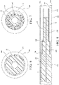
- the stent graft 10 With the stent graft 10 mounted in the configuration shown in FIG. 3 , the stent graft 10 is then compacted generally radially onto the core member 300 and retained in the delivery configuration by the sheath 200, as shown in FIGS. 4-8 . As best shown in the cross sectional view of FIG. 7 (taken along the plane indicated at 7-7 in FIG. 5 ), the second leg 40 is compacted along a portion of a circumference of the third section 330, while the first leg 30 is compacted and generally co-axially aligned with the third section 330.
- the second leg 40 adds column strength to the stent graft 10 along the core member 300 to help prevent axial crumpling of the stent graft 10 during axial displacement of the sheath 200 relative to the core.
- the sheath 200 is displaced axially along a direction, generally indicated by arrow "a" in FIG. 8 , relative to the core member 300.
- Abutment between the terminal ends 32 and 42 of the first 30 and second 40 legs, respectively, and the first 350 and second 360 end surfaces prevents axial displacement of the stent graft 10 due to friction between the stent graft 10 and the sheath 200 as the sheath 200 is displaced.
- the enhanced column strength of the compacted stent graft along the third section 330 of the core member 300 also helps to resist axial crumpling the stent graft also due to friction between the stent graft 10 and the sheath 200 as the sheath 200 is displaced relative to the core member 300.
- Axial displacement of the sheath 200 relative to the core member 300 allows outward expansion of the stent graft 10 from the delivery configuration.
- secondary sheaths or constraining sleeves can be utilized to limit expansion of the stent graft to an intermediate configuration larger than the delivery configuration and smaller than a fully deployed configuration engaged with vessel walls. Further details of such constraining sleeves can be found, for example, in U.S. Pat. No. 6,352,561 issued to Leopold, et al. , U.S. Pat. No. 6,551,350 issued to Thornton, et al. , as well as co-pending U.S. Patent Application Publication US 2010/0049293 A1 (Zukowski et al. ).
- the core member 300 and sheath 200 can be removed from the treatment site and body of the patient.
Landscapes
- Health & Medical Sciences (AREA)
- Engineering & Computer Science (AREA)
- Biomedical Technology (AREA)
- Heart & Thoracic Surgery (AREA)
- Public Health (AREA)
- Transplantation (AREA)
- Cardiology (AREA)
- Veterinary Medicine (AREA)
- Oral & Maxillofacial Surgery (AREA)
- Vascular Medicine (AREA)
- Life Sciences & Earth Sciences (AREA)
- Animal Behavior & Ethology (AREA)
- General Health & Medical Sciences (AREA)
- Gastroenterology & Hepatology (AREA)
- Pulmonology (AREA)
- Prostheses (AREA)
- Media Introduction/Drainage Providing Device (AREA)
Description
- The present disclosure relates to medical device deployment systems for bifurcated stent grafts.
- There is a need for advanced devices, tools, systems and methods used for the endoluminal treatment of aortic diseases. In particular, there remains a need for deployment systems that can accommodate increasingly complex modes of deployment of a device, such as steering, reconstraining, multiple stage deployment, multiple device deployment, while promoting ease of use to the clinician. There also remains a need for increasingly reduced profile delivery mechanisms.
-
US 2007/0050015 A1 discloses a bifurcated endoluminal device compressed for endoluminal placement in an outer sheath and mounted on guidewire tube. An inner sheath terminates just proximal of the proximal end of second branch portion and pusher element is disposed just proximal of first branch portion.WO 2007/025101 A2 discloses an endoluminal device adapted to be deployed in a branched body lumen provided by intraluminal delivery from an access location remote from the location at which the device is to be deployed, i.e. by introduction through one of the branches of the branched body lumen. The device comprises an unbranched portion, a first branch portion and second branch portion in communication with the unbranched portion, and a distortion element removeably connected to the first branch portion for manipulating the geometry of the second branch portion. The distortion element extends along the first branch portion and back to the access location. - The accompanying drawings are included to provide a further understanding of the present disclosure and are incorporated in and constitute a part of this specification, illustrate embodiments of the present disclosure, and together with the description serve to explain the principles of the present disclosure.
-
FIGS. 1-3 illustrate a bifurcated stent graft and a portion of a deployment system in accordance with various embodiments; -
FIGS. 4-5 illustrate a bifurcated stent graft retained in a delivery configuration by a deployment system in accordance with various embodiments; -
FIGS. 6-7 are cross sectional views of the bifurcated stent graft and deployment system as taken along planes indicated at 6-6 and 7-7 inFIG. 5 , respectively; and -
FIG. 8 is a longitudinal cross sectional view of the bifurcated stent graft and deployment system inFIG. 5 . - In various embodiments, a system for endoluminal delivery of a medical device includes a bifurcated stent graft comprising a trunk, a first leg and a second leg, wherein the first leg is longer than the second leg; a sheath having a tubular wall having a cylindrical inner surface defining a lumen for receiving the stent graft therein to constrain the stent graft toward a delivery configuration suitable for endoluminal delivery; and a generally cylindrical core member extending through the lumen, the core member having a first section having a first diameter, a second section having a second diameter smaller than the first diameter, and a third section having a third diameter smaller than the second diameter, the core having an annular first end surface between the first and second sections, and an annular second end surface between the second and third sections, wherein the first and second ends surfaces of the core member engage respective axially spaced apart portions of the stent graft during axial displacement of the sheath with respect to the core member.
- Referring to
FIGS. 1-8 , for example, a delivery system for delivery of a bifurcatedstent graft 10 is generally indicated at 100. As shown, thestent graft 10 includes atrunk 20, afirst leg 30 and asecond leg 40, wherein thefirst leg 30 is longer than thesecond leg 40. The delivery system 100 includes asheath 200 having atubular wall 210. The tubular wall includes anouter surface 212 and an oppositeinner surface 214 defining alumen 216. Thelumen 216 is configured to receive thestent graft 10 therein to constrain and maintain thestent graft 10 in a delivery configuration suitable for endoluminal delivery to a vascular treatment site. - The delivery system 100 includes a
core member 300. Thecore member 300 has alongitudinal axis 302 and through thelumen 216 of thesheath 200. Thecore member 300 includes afirst section 310 having a first diameter. Thecore member 300 includes asecond section 320 having a second diameter smaller than the first diameter. Thecore member 300 includes athird section 330 having a third diameter smaller than the second diameter. - The
core member 300 includes an annularfirst end surface 350 between the first 310 and second 320 sections. Thefirst end surface 350 can be substantially normal to thelongitudinal axis 302 of thecore member 300. Similarly, thecore member 300 includes an annularsecond end surface 360 between the second 320 and third 330 sections. Thesecond end surface 360 can be substantially normal to thelongitudinal axis 302 of thecore member 300. - During assembly, the
core member 300 can be inserted through thefirst leg 30 of thestent graft 10, as shown inFIG. 1 , until aterminal end 32 of thefirst leg 30 abuts thefirst end surface 350, as shown inFIGS. 2 and 3 . A terminal end 42 of thesecond leg 40 of thestent graft 10 is generally aligned axially with thesecond end surface 360, as indicated at plane "P" inFIG. 3 . - With the
stent graft 10 mounted in the configuration shown inFIG. 3 , thestent graft 10 is then compacted generally radially onto thecore member 300 and retained in the delivery configuration by thesheath 200, as shown inFIGS. 4-8 . As best shown in the cross sectional view ofFIG. 7 (taken along the plane indicated at 7-7 inFIG. 5 ), thesecond leg 40 is compacted along a portion of a circumference of thethird section 330, while thefirst leg 30 is compacted and generally co-axially aligned with thethird section 330. - By this arrangement, the
second leg 40 adds column strength to thestent graft 10 along thecore member 300 to help prevent axial crumpling of thestent graft 10 during axial displacement of thesheath 200 relative to the core. Thus, during deployment of thestent graft 10, thesheath 200 is displaced axially along a direction, generally indicated by arrow "a" inFIG. 8 , relative to thecore member 300. Abutment between the terminal ends 32 and 42 of the first 30 and second 40 legs, respectively, and the first 350 and second 360 end surfaces prevents axial displacement of thestent graft 10 due to friction between thestent graft 10 and thesheath 200 as thesheath 200 is displaced. The enhanced column strength of the compacted stent graft along thethird section 330 of thecore member 300 also helps to resist axial crumpling the stent graft also due to friction between thestent graft 10 and thesheath 200 as thesheath 200 is displaced relative to thecore member 300. - Axial displacement of the
sheath 200 relative to thecore member 300 allows outward expansion of thestent graft 10 from the delivery configuration. Optionally, secondary sheaths or constraining sleeves can be utilized to limit expansion of the stent graft to an intermediate configuration larger than the delivery configuration and smaller than a fully deployed configuration engaged with vessel walls. Further details of such constraining sleeves can be found, for example, inU.S. Pat. No. 6,352,561 issued to Leopold, et al. ,U.S. Pat. No. 6,551,350 issued to Thornton, et al. , as well as co-pending U.S. Patent Application PublicationUS 2010/0049293 A1 (Zukowski et al. ). - Upon full deployment of the
stent graft 10, thecore member 300 andsheath 200 can be removed from the treatment site and body of the patient. - It will be apparent to those skilled in the art that various modifications and variations can be made in the present disclosure without departing from the scope of the present disclosure. Thus, it is intended that the present disclosure cover the modifications and variations of this present disclosure provided they come within the scope of the appended claims.
Claims (8)
- A system (100) for endoluminal delivery of a medical device, wherein the medical device includes a bifurcated stent graft (10) having a trunk (20), a first leg (30) and a second leg (40) shorter than the first leg (30), said system (100) comprising:a sheath (200) having a tubular wall (210) having a cylindrical inner surface (214) defining a lumen (216) for receiving the stent graft (10) therein to constrain the stent graft (10) toward a delivery configuration suitable for endoluminal delivery; anda generally cylindrical core member (300) extending through the lumen (216), the core member (300) having first annular surface (350) for engaging an end (32) of the first leg (30), the core member (300) having a second annular surface (360) for engaging an end (42) of the second leg (40) while the second annular surface (360) is positioned within a lumen of the first leg (30); and at least the end (42) of the second leg (40) remains constrained by the sheath (200);wherein the core member (300) includes a first section (310) having a first diameter and a second section (320) having a second diameter, the first diameter being larger than the second diameter; andwherein the first annular surface (350) extends between an outer surface of the first section (310) and an outer surface of the second section (320).
- The system (100) as set forth in claim 1, wherein the first annular surface (350) is normal relative to a longitudinal axis (302) of the core member (300).
- The system (100) as set forth in claim 1, wherein the core member (300) includes a third section (330) having a third diameter, the second diameter being larger than the third diameter.
- The system (100) as set forth in claim 3, wherein the second annular surface (360) extends between the outer surface of the second section (320) and an outer surface of the third section (330).
- The system (100) as set forth in claim 4, wherein the second annular surface (360) is normal relative to a longitudinal axis (302) of the core member (300).
- The system (100) as set forth in claim 4, wherein the first annular surface (350) and the second annular surface (360) are parallel.
- The system (100) of claim 3, wherein the first (310), second (320) and third (330) sections of the core member (300) are coaxially aligned.
- The system (100) as set forth in claim 1, wherein the second (320) and third (330) sections of the core member (300) extend through the first leg (30) of the bifurcated stent graft (10).
Priority Applications (1)
| Application Number | Priority Date | Filing Date | Title |
|---|---|---|---|
| EP22171483.5A EP4074289A1 (en) | 2014-04-04 | 2015-04-01 | Delivery and deployment systems for bifurcated stent grafts |
Applications Claiming Priority (3)
| Application Number | Priority Date | Filing Date | Title |
|---|---|---|---|
| US201461975217P | 2014-04-04 | 2014-04-04 | |
| US14/675,368 US9974675B2 (en) | 2014-04-04 | 2015-03-31 | Delivery and deployment systems for bifurcated stent grafts |
| PCT/US2015/023874 WO2015153754A1 (en) | 2014-04-04 | 2015-04-01 | Delivery and deployment systems for bifurcated stent grafts |
Related Child Applications (1)
| Application Number | Title | Priority Date | Filing Date |
|---|---|---|---|
| EP22171483.5A Division EP4074289A1 (en) | 2014-04-04 | 2015-04-01 | Delivery and deployment systems for bifurcated stent grafts |
Publications (2)
| Publication Number | Publication Date |
|---|---|
| EP3125831A1 EP3125831A1 (en) | 2017-02-08 |
| EP3125831B1 true EP3125831B1 (en) | 2022-06-01 |
Family
ID=54208738
Family Applications (2)
| Application Number | Title | Priority Date | Filing Date |
|---|---|---|---|
| EP15721904.9A Active EP3125831B1 (en) | 2014-04-04 | 2015-04-01 | Delivery and deployment systems for bifurcated stent grafts |
| EP22171483.5A Pending EP4074289A1 (en) | 2014-04-04 | 2015-04-01 | Delivery and deployment systems for bifurcated stent grafts |
Family Applications After (1)
| Application Number | Title | Priority Date | Filing Date |
|---|---|---|---|
| EP22171483.5A Pending EP4074289A1 (en) | 2014-04-04 | 2015-04-01 | Delivery and deployment systems for bifurcated stent grafts |
Country Status (9)
| Country | Link |
|---|---|
| US (3) | US9974675B2 (en) |
| EP (2) | EP3125831B1 (en) |
| JP (2) | JP6549610B2 (en) |
| KR (1) | KR102422686B1 (en) |
| CN (2) | CN106163451B (en) |
| AU (1) | AU2015240807B2 (en) |
| CA (1) | CA2944145C (en) |
| ES (1) | ES2924984T3 (en) |
| WO (1) | WO2015153754A1 (en) |
Families Citing this family (3)
| Publication number | Priority date | Publication date | Assignee | Title |
|---|---|---|---|---|
| US9974675B2 (en) | 2014-04-04 | 2018-05-22 | W. L. Gore & Associates, Inc. | Delivery and deployment systems for bifurcated stent grafts |
| US10149777B2 (en) * | 2014-12-18 | 2018-12-11 | Cook Medical Technologies Llc | Orientation marker on pusher for deployment of endoluminal prostheses |
| CN110520082B (en) | 2017-03-06 | 2022-02-18 | 心血管实验室股份公司和布雷维蒙特 Cv 实验室股份公司 | Multi-layer intraluminal prosthetic assembly and method of making same |
Citations (2)
| Publication number | Priority date | Publication date | Assignee | Title |
|---|---|---|---|---|
| WO2007025101A2 (en) * | 2005-08-25 | 2007-03-01 | Boston Scientific Scimed, Inc. | Endoluminal prosthesis adapted to deployment in a distorted branched body lumen |
| US20090132026A1 (en) * | 2007-11-16 | 2009-05-21 | Boston Scientific Corporation | Delivery system and method for bifurcated graft |
Family Cites Families (71)
| Publication number | Priority date | Publication date | Assignee | Title |
|---|---|---|---|---|
| US5628783A (en) * | 1991-04-11 | 1997-05-13 | Endovascular Technologies, Inc. | Bifurcated multicapsule intraluminal grafting system and method |
| US5609627A (en) * | 1994-02-09 | 1997-03-11 | Boston Scientific Technology, Inc. | Method for delivering a bifurcated endoluminal prosthesis |
| US7604633B2 (en) | 1996-04-12 | 2009-10-20 | Cytyc Corporation | Moisture transport system for contact electrocoagulation |
| FR2748197A1 (en) | 1996-05-02 | 1997-11-07 | Braun Celsa Sa | Surgical implant positioning device |
| US6770092B2 (en) * | 1996-05-03 | 2004-08-03 | Medinol Ltd. | Method of delivering a bifurcated stent |
| US8211167B2 (en) * | 1999-12-06 | 2012-07-03 | Boston Scientific Scimed, Inc. | Method of using a catheter with attached flexible side sheath |
| US5860998A (en) * | 1996-11-25 | 1999-01-19 | C. R. Bard, Inc. | Deployment device for tubular expandable prosthesis |
| US6551350B1 (en) | 1996-12-23 | 2003-04-22 | Gore Enterprise Holdings, Inc. | Kink resistant bifurcated prosthesis |
| US6352561B1 (en) | 1996-12-23 | 2002-03-05 | W. L. Gore & Associates | Implant deployment apparatus |
| US5928248A (en) * | 1997-02-14 | 1999-07-27 | Biosense, Inc. | Guided deployment of stents |
| US6951572B1 (en) * | 1997-02-20 | 2005-10-04 | Endologix, Inc. | Bifurcated vascular graft and method and apparatus for deploying same |
| US5792144A (en) | 1997-03-31 | 1998-08-11 | Cathco, Inc. | Stent delivery catheter system |
| AUPO700897A0 (en) | 1997-05-26 | 1997-06-19 | William A Cook Australia Pty Ltd | A method and means of deploying a graft |
| CA2310088C (en) * | 1997-11-14 | 2008-12-16 | Carl E. Yee | Multi-sheath delivery catheter |
| US6120522A (en) * | 1998-08-27 | 2000-09-19 | Scimed Life Systems, Inc. | Self-expanding stent delivery catheter |
| US6203550B1 (en) | 1998-09-30 | 2001-03-20 | Medtronic, Inc. | Disposable delivery device for endoluminal prostheses |
| US6368345B1 (en) * | 1998-09-30 | 2002-04-09 | Edwards Lifesciences Corporation | Methods and apparatus for intraluminal placement of a bifurcated intraluminal garafat |
| US6241758B1 (en) | 1999-05-28 | 2001-06-05 | Advanced Cardiovascular Systems, Inc. | Self-expanding stent delivery system and method of use |
| ATE258768T1 (en) * | 1999-08-05 | 2004-02-15 | Broncus Tech Inc | METHOD AND DEVICES FOR PRODUCING COLLATERAL CHANNELS IN THE LUNGS |
| US6689156B1 (en) * | 1999-09-23 | 2004-02-10 | Advanced Stent Technologies, Inc. | Stent range transducers and methods of use |
| JP2005506109A (en) * | 2001-03-28 | 2005-03-03 | クック インコーポレイティド | Modular stent graft assembly and method of use |
| US6733521B2 (en) | 2001-04-11 | 2004-05-11 | Trivascular, Inc. | Delivery system and method for endovascular graft |
| AUPR847301A0 (en) | 2001-10-26 | 2001-11-15 | Cook Incorporated | Endoluminal prostheses for curved lumens |
| US7147661B2 (en) | 2001-12-20 | 2006-12-12 | Boston Scientific Santa Rosa Corp. | Radially expandable stent |
| US20100016943A1 (en) | 2001-12-20 | 2010-01-21 | Trivascular2, Inc. | Method of delivering advanced endovascular graft |
| GB0203177D0 (en) | 2002-02-11 | 2002-03-27 | Anson Medical Ltd | An improved control mechanism for medical catheters |
| US6911039B2 (en) | 2002-04-23 | 2005-06-28 | Medtronic Vascular, Inc. | Integrated mechanical handle with quick slide mechanism |
| US7550002B2 (en) | 2002-04-30 | 2009-06-23 | Olympus Corporation | Stent delivery device |
| US7081132B2 (en) | 2002-05-16 | 2006-07-25 | Cook Incorporated | Flexible barb for anchoring a prosthesis |
| RU2005108673A (en) | 2002-08-29 | 2006-01-20 | Митралсолюшнз, Инк. (Us) | IMPLANTED DEVICES FOR REGULATING THE INTERNAL CIRCLE OF ANATOMIC HOLE OR LIGHT |
| WO2004080504A2 (en) | 2003-03-10 | 2004-09-23 | Wilson-Cook Medical, Inc. | Stent introducer apparatus |
| US8262671B2 (en) | 2003-03-14 | 2012-09-11 | Oscor Inc. | Vascular introducer having hemostatic valve with integral seal |
| US20040267348A1 (en) * | 2003-04-11 | 2004-12-30 | Gunderson Richard C. | Medical device delivery systems |
| US20050050015A1 (en) | 2003-08-29 | 2005-03-03 | Dirk Becker | Generic iViews |
| US7651519B2 (en) | 2003-09-16 | 2010-01-26 | Cook Incorporated | Prosthesis deployment system |
| EP3028681B1 (en) | 2003-10-14 | 2019-12-25 | Cook Medical Technologies LLC | Introducer for an iliac side branch device |
| US8109983B2 (en) * | 2004-08-06 | 2012-02-07 | Boston Scientific Scimed, Inc. | Medical device delivery systems |
| US7740652B2 (en) * | 2005-03-30 | 2010-06-22 | Boston Scientific Scimed, Inc. | Catheter |
| US8608789B2 (en) * | 2005-05-24 | 2013-12-17 | Trireme Medical, Inc. | Delivery system for bifurcation stents |
| US7938851B2 (en) | 2005-06-08 | 2011-05-10 | Xtent, Inc. | Devices and methods for operating and controlling interventional apparatus |
| JP2009504345A (en) | 2005-08-17 | 2009-02-05 | シー・アール・バード・インコーポレーテッド | Variable speed stent delivery system |
| CN102188296A (en) * | 2005-10-20 | 2011-09-21 | 阿普特斯内系统公司 | Devices, systems, and methods for prosthesis delivery and implantation |
| CA2649705C (en) * | 2006-04-19 | 2015-12-01 | William A. Cook Australia Pty. Ltd | Twin bifurcated stent graft |
| US9585743B2 (en) | 2006-07-31 | 2017-03-07 | Edwards Lifesciences Cardiaq Llc | Surgical implant devices and methods for their manufacture and use |
| US8257431B2 (en) | 2006-11-01 | 2012-09-04 | Boston Scientific Scimed, Inc. | Multi-furcated ePTFE grafts and stent-graft prostheses and methods of making the same |
| US7655034B2 (en) | 2006-11-14 | 2010-02-02 | Medtronic Vascular, Inc. | Stent-graft with anchoring pins |
| WO2008066917A1 (en) | 2006-11-30 | 2008-06-05 | William Cook Europe Aps | Pusher sheath and deployment device |
| EP2497520B1 (en) * | 2007-07-18 | 2022-04-13 | Silk Road Medical, Inc. | Systems for establishing retrograde carotid arterial blood flow |
| JP5380653B2 (en) | 2008-02-11 | 2014-01-08 | クック メディカル テクノロジーズ エルエルシー | Curvature device and bendable stent graft |
| DE102008012113A1 (en) | 2008-03-02 | 2009-09-03 | Transcatheter Technologies Gmbh | Implant e.g. heart-valve-carrying stent, for e.g. arresting blood vessel, has fiber by which section of implant is reducible according to increasing of implant at extended diameter by unfolding or expansion of diameter with expansion unit |
| US20090259296A1 (en) * | 2008-04-10 | 2009-10-15 | Medtronic Vascular, Inc. | Gate Cannulation Apparatus and Methods |
| US8236040B2 (en) * | 2008-04-11 | 2012-08-07 | Endologix, Inc. | Bifurcated graft deployment systems and methods |
| JP5536764B2 (en) | 2008-06-04 | 2014-07-02 | ゴア エンタープライズ ホールディングス,インコーポレイティド | Medical device capable of controlled deployment and manufacturing method thereof |
| ES2749741T3 (en) * | 2008-06-30 | 2020-03-23 | Bolton Medical Inc | Abdominal aortic aneurysm systems |
| JP5134729B2 (en) | 2008-07-01 | 2013-01-30 | エンドロジックス、インク | Catheter system |
| GB2464978B (en) | 2008-10-31 | 2010-10-20 | Cook William Europ | Introducer for deploying a stent graft in a curved lumen |
| EP2490629B1 (en) | 2009-10-20 | 2019-05-22 | Cook Medical Technologies, LLC | Rotational controlled deployment device |
| EP4275660A3 (en) * | 2010-03-24 | 2024-01-17 | Advanced Bifurcation Systems Inc. | Selective stent crimping |
| US20110251664A1 (en) | 2010-04-08 | 2011-10-13 | Medtronic Vascular, Inc. | Short Legged Bifurcated Stent Graft Distal Capture Element and Method |
| US9265599B2 (en) * | 2011-08-31 | 2016-02-23 | Cleveland Clinic Foundation | Retention system for an endoluminal device |
| US9072624B2 (en) * | 2012-02-23 | 2015-07-07 | Covidien Lp | Luminal stenting |
| US8968384B2 (en) | 2012-04-27 | 2015-03-03 | Medtronic Vascular, Inc. | Circumferentially constraining sutures for a stent-graft |
| US9132025B2 (en) | 2012-06-15 | 2015-09-15 | Trivascular, Inc. | Bifurcated endovascular prosthesis having tethered contralateral leg |
| EP2745812B1 (en) | 2012-12-19 | 2017-01-18 | Cook Medical Technologies LLC | Repositionable diameter constraints |
| US10350096B2 (en) | 2012-12-26 | 2019-07-16 | Cook Medical Technologies Llc | Expandable stent-graft system having diameter reducing connectors |
| US9308349B2 (en) | 2013-02-08 | 2016-04-12 | Vention Medical Advanced Components, Inc. | Universal catheter handle |
| US9254204B2 (en) | 2013-03-15 | 2016-02-09 | Cook Medical Technologies Llc | Stents having barbs protected during delivery |
| EP3275496B1 (en) | 2013-05-07 | 2019-08-21 | St. Jude Medical, Atrial Fibrillation Division, Inc. | Control handle for deflectable catheter |
| US9974675B2 (en) | 2014-04-04 | 2018-05-22 | W. L. Gore & Associates, Inc. | Delivery and deployment systems for bifurcated stent grafts |
| EP3284446B1 (en) | 2014-12-04 | 2018-12-19 | Cook Medical Technologies LLC | Delivery device handle assembly for the sequential deployment of a prosthesis |
| CN109069282A (en) | 2016-04-05 | 2018-12-21 | 波顿医疗公司 | Delivery system and application method with guide and distal sheath |
-
2015
- 2015-03-31 US US14/675,368 patent/US9974675B2/en active Active
- 2015-04-01 EP EP15721904.9A patent/EP3125831B1/en active Active
- 2015-04-01 CN CN201580017682.XA patent/CN106163451B/en active Active
- 2015-04-01 CN CN201910067082.4A patent/CN109620468B/en active Active
- 2015-04-01 AU AU2015240807A patent/AU2015240807B2/en active Active
- 2015-04-01 JP JP2016560654A patent/JP6549610B2/en active Active
- 2015-04-01 KR KR1020167031011A patent/KR102422686B1/en active IP Right Grant
- 2015-04-01 ES ES15721904T patent/ES2924984T3/en active Active
- 2015-04-01 EP EP22171483.5A patent/EP4074289A1/en active Pending
- 2015-04-01 CA CA2944145A patent/CA2944145C/en active Active
- 2015-04-01 WO PCT/US2015/023874 patent/WO2015153754A1/en active Application Filing
-
2018
- 2018-05-18 US US15/983,186 patent/US11690742B2/en active Active
-
2019
- 2019-06-27 JP JP2019119784A patent/JP2019195647A/en active Pending
-
2023
- 2023-05-24 US US18/201,260 patent/US20230293326A1/en active Pending
Patent Citations (2)
| Publication number | Priority date | Publication date | Assignee | Title |
|---|---|---|---|---|
| WO2007025101A2 (en) * | 2005-08-25 | 2007-03-01 | Boston Scientific Scimed, Inc. | Endoluminal prosthesis adapted to deployment in a distorted branched body lumen |
| US20090132026A1 (en) * | 2007-11-16 | 2009-05-21 | Boston Scientific Corporation | Delivery system and method for bifurcated graft |
Also Published As
| Publication number | Publication date |
|---|---|
| US20180263800A1 (en) | 2018-09-20 |
| KR102422686B1 (en) | 2022-07-18 |
| US20230293326A1 (en) | 2023-09-21 |
| WO2015153754A1 (en) | 2015-10-08 |
| CA2944145A1 (en) | 2015-10-08 |
| ES2924984T3 (en) | 2022-10-13 |
| US9974675B2 (en) | 2018-05-22 |
| JP6549610B2 (en) | 2019-07-24 |
| CN106163451B (en) | 2019-02-26 |
| JP2017509437A (en) | 2017-04-06 |
| US20150282967A1 (en) | 2015-10-08 |
| CA2944145C (en) | 2019-09-17 |
| EP4074289A1 (en) | 2022-10-19 |
| KR20160145065A (en) | 2016-12-19 |
| CN106163451A (en) | 2016-11-23 |
| AU2015240807B2 (en) | 2018-03-01 |
| CN109620468B (en) | 2021-07-30 |
| US11690742B2 (en) | 2023-07-04 |
| AU2015240807A1 (en) | 2016-11-17 |
| EP3125831A1 (en) | 2017-02-08 |
| JP2019195647A (en) | 2019-11-14 |
| CN109620468A (en) | 2019-04-16 |
Similar Documents
| Publication | Publication Date | Title |
|---|---|---|
| US20230293326A1 (en) | Delivery and deployment systems for bifurcated stent grafts | |
| JP5347175B2 (en) | Introducer | |
| EP2563286B1 (en) | Stent graft delivery system | |
| EP1694249B1 (en) | Biliary stent introducer system | |
| JP2007190377A (en) | Stent delivery system with improved delivery force distribution | |
| US8747448B2 (en) | Stent graft delivery system | |
| EP3398568B1 (en) | Delivery system and lumen stent system | |
| CN104042380A (en) | Delivery system for expandable stents | |
| WO2008034106A3 (en) | Multi-segmented graft deployment system | |
| CA2440487C (en) | Delivery system for delivering a self-expanding stent | |
| WO2001054614A3 (en) | Self-expanding stent with enhanced delivery precision and stent delivery system | |
| WO2008039910A3 (en) | Medical catheter removal | |
| EP2870947B1 (en) | An endograft introducer and a capsule assembly for an endograft introducer | |
| US20210186728A1 (en) | Scaffold loading and delivery systems | |
| EP3069695B1 (en) | An endograft introducer assembly having a transfer sheath | |
| IE20060620A1 (en) | A delivery catheter |
Legal Events
| Date | Code | Title | Description |
|---|---|---|---|
| STAA | Information on the status of an ep patent application or granted ep patent |
Free format text: STATUS: THE INTERNATIONAL PUBLICATION HAS BEEN MADE |
|
| PUAI | Public reference made under article 153(3) epc to a published international application that has entered the european phase |
Free format text: ORIGINAL CODE: 0009012 |
|
| STAA | Information on the status of an ep patent application or granted ep patent |
Free format text: STATUS: REQUEST FOR EXAMINATION WAS MADE |
|
| 17P | Request for examination filed |
Effective date: 20160923 |
|
| AK | Designated contracting states |
Kind code of ref document: A1 Designated state(s): AL AT BE BG CH CY CZ DE DK EE ES FI FR GB GR HR HU IE IS IT LI LT LU LV MC MK MT NL NO PL PT RO RS SE SI SK SM TR |
|
| AX | Request for extension of the european patent |
Extension state: BA ME |
|
| DAV | Request for validation of the european patent (deleted) | ||
| DAX | Request for extension of the european patent (deleted) | ||
| STAA | Information on the status of an ep patent application or granted ep patent |
Free format text: STATUS: EXAMINATION IS IN PROGRESS |
|
| 17Q | First examination report despatched |
Effective date: 20170908 |
|
| REG | Reference to a national code |
Ref country code: HK Ref legal event code: DE Ref document number: 1232764 Country of ref document: HK |
|
| STAA | Information on the status of an ep patent application or granted ep patent |
Free format text: STATUS: EXAMINATION IS IN PROGRESS |
|
| GRAP | Despatch of communication of intention to grant a patent |
Free format text: ORIGINAL CODE: EPIDOSNIGR1 |
|
| STAA | Information on the status of an ep patent application or granted ep patent |
Free format text: STATUS: GRANT OF PATENT IS INTENDED |
|
| INTG | Intention to grant announced |
Effective date: 20211201 |
|
| GRAS | Grant fee paid |
Free format text: ORIGINAL CODE: EPIDOSNIGR3 |
|
| GRAA | (expected) grant |
Free format text: ORIGINAL CODE: 0009210 |
|
| STAA | Information on the status of an ep patent application or granted ep patent |
Free format text: STATUS: THE PATENT HAS BEEN GRANTED |
|
| AK | Designated contracting states |
Kind code of ref document: B1 Designated state(s): AL AT BE BG CH CY CZ DE DK EE ES FI FR GB GR HR HU IE IS IT LI LT LU LV MC MK MT NL NO PL PT RO RS SE SI SK SM TR |
|
| REG | Reference to a national code |
Ref country code: GB Ref legal event code: FG4D |
|
| REG | Reference to a national code |
Ref country code: AT Ref legal event code: REF Ref document number: 1494889 Country of ref document: AT Kind code of ref document: T Effective date: 20220615 Ref country code: CH Ref legal event code: EP Ref country code: DE Ref legal event code: R096 Ref document number: 602015079240 Country of ref document: DE |
|
| REG | Reference to a national code |
Ref country code: IE Ref legal event code: FG4D |
|
| REG | Reference to a national code |
Ref country code: LT Ref legal event code: MG9D |
|
| REG | Reference to a national code |
Ref country code: NL Ref legal event code: MP Effective date: 20220601 |
|
| REG | Reference to a national code |
Ref country code: ES Ref legal event code: FG2A Ref document number: 2924984 Country of ref document: ES Kind code of ref document: T3 Effective date: 20221013 |
|
| PG25 | Lapsed in a contracting state [announced via postgrant information from national office to epo] |
Ref country code: SE Free format text: LAPSE BECAUSE OF FAILURE TO SUBMIT A TRANSLATION OF THE DESCRIPTION OR TO PAY THE FEE WITHIN THE PRESCRIBED TIME-LIMIT Effective date: 20220601 Ref country code: NO Free format text: LAPSE BECAUSE OF FAILURE TO SUBMIT A TRANSLATION OF THE DESCRIPTION OR TO PAY THE FEE WITHIN THE PRESCRIBED TIME-LIMIT Effective date: 20220901 Ref country code: LT Free format text: LAPSE BECAUSE OF FAILURE TO SUBMIT A TRANSLATION OF THE DESCRIPTION OR TO PAY THE FEE WITHIN THE PRESCRIBED TIME-LIMIT Effective date: 20220601 Ref country code: HR Free format text: LAPSE BECAUSE OF FAILURE TO SUBMIT A TRANSLATION OF THE DESCRIPTION OR TO PAY THE FEE WITHIN THE PRESCRIBED TIME-LIMIT Effective date: 20220601 Ref country code: GR Free format text: LAPSE BECAUSE OF FAILURE TO SUBMIT A TRANSLATION OF THE DESCRIPTION OR TO PAY THE FEE WITHIN THE PRESCRIBED TIME-LIMIT Effective date: 20220902 Ref country code: FI Free format text: LAPSE BECAUSE OF FAILURE TO SUBMIT A TRANSLATION OF THE DESCRIPTION OR TO PAY THE FEE WITHIN THE PRESCRIBED TIME-LIMIT Effective date: 20220601 Ref country code: BG Free format text: LAPSE BECAUSE OF FAILURE TO SUBMIT A TRANSLATION OF THE DESCRIPTION OR TO PAY THE FEE WITHIN THE PRESCRIBED TIME-LIMIT Effective date: 20220901 |
|
| REG | Reference to a national code |
Ref country code: AT Ref legal event code: MK05 Ref document number: 1494889 Country of ref document: AT Kind code of ref document: T Effective date: 20220601 |
|
| PG25 | Lapsed in a contracting state [announced via postgrant information from national office to epo] |
Ref country code: RS Free format text: LAPSE BECAUSE OF FAILURE TO SUBMIT A TRANSLATION OF THE DESCRIPTION OR TO PAY THE FEE WITHIN THE PRESCRIBED TIME-LIMIT Effective date: 20220601 Ref country code: PL Free format text: LAPSE BECAUSE OF FAILURE TO SUBMIT A TRANSLATION OF THE DESCRIPTION OR TO PAY THE FEE WITHIN THE PRESCRIBED TIME-LIMIT Effective date: 20220601 Ref country code: LV Free format text: LAPSE BECAUSE OF FAILURE TO SUBMIT A TRANSLATION OF THE DESCRIPTION OR TO PAY THE FEE WITHIN THE PRESCRIBED TIME-LIMIT Effective date: 20220601 |
|
| PG25 | Lapsed in a contracting state [announced via postgrant information from national office to epo] |
Ref country code: NL Free format text: LAPSE BECAUSE OF FAILURE TO SUBMIT A TRANSLATION OF THE DESCRIPTION OR TO PAY THE FEE WITHIN THE PRESCRIBED TIME-LIMIT Effective date: 20220601 |
|
| PG25 | Lapsed in a contracting state [announced via postgrant information from national office to epo] |
Ref country code: SM Free format text: LAPSE BECAUSE OF FAILURE TO SUBMIT A TRANSLATION OF THE DESCRIPTION OR TO PAY THE FEE WITHIN THE PRESCRIBED TIME-LIMIT Effective date: 20220601 Ref country code: SK Free format text: LAPSE BECAUSE OF FAILURE TO SUBMIT A TRANSLATION OF THE DESCRIPTION OR TO PAY THE FEE WITHIN THE PRESCRIBED TIME-LIMIT Effective date: 20220601 Ref country code: RO Free format text: LAPSE BECAUSE OF FAILURE TO SUBMIT A TRANSLATION OF THE DESCRIPTION OR TO PAY THE FEE WITHIN THE PRESCRIBED TIME-LIMIT Effective date: 20220601 Ref country code: PT Free format text: LAPSE BECAUSE OF FAILURE TO SUBMIT A TRANSLATION OF THE DESCRIPTION OR TO PAY THE FEE WITHIN THE PRESCRIBED TIME-LIMIT Effective date: 20221003 Ref country code: EE Free format text: LAPSE BECAUSE OF FAILURE TO SUBMIT A TRANSLATION OF THE DESCRIPTION OR TO PAY THE FEE WITHIN THE PRESCRIBED TIME-LIMIT Effective date: 20220601 Ref country code: CZ Free format text: LAPSE BECAUSE OF FAILURE TO SUBMIT A TRANSLATION OF THE DESCRIPTION OR TO PAY THE FEE WITHIN THE PRESCRIBED TIME-LIMIT Effective date: 20220601 Ref country code: AT Free format text: LAPSE BECAUSE OF FAILURE TO SUBMIT A TRANSLATION OF THE DESCRIPTION OR TO PAY THE FEE WITHIN THE PRESCRIBED TIME-LIMIT Effective date: 20220601 |
|
| PG25 | Lapsed in a contracting state [announced via postgrant information from national office to epo] |
Ref country code: IS Free format text: LAPSE BECAUSE OF FAILURE TO SUBMIT A TRANSLATION OF THE DESCRIPTION OR TO PAY THE FEE WITHIN THE PRESCRIBED TIME-LIMIT Effective date: 20221001 |
|
| REG | Reference to a national code |
Ref country code: DE Ref legal event code: R097 Ref document number: 602015079240 Country of ref document: DE |
|
| REG | Reference to a national code |
Ref country code: FR Ref legal event code: PLFP Year of fee payment: 9 |
|
| PG25 | Lapsed in a contracting state [announced via postgrant information from national office to epo] |
Ref country code: AL Free format text: LAPSE BECAUSE OF FAILURE TO SUBMIT A TRANSLATION OF THE DESCRIPTION OR TO PAY THE FEE WITHIN THE PRESCRIBED TIME-LIMIT Effective date: 20220601 |
|
| PLBE | No opposition filed within time limit |
Free format text: ORIGINAL CODE: 0009261 |
|
| STAA | Information on the status of an ep patent application or granted ep patent |
Free format text: STATUS: NO OPPOSITION FILED WITHIN TIME LIMIT |
|
| PG25 | Lapsed in a contracting state [announced via postgrant information from national office to epo] |
Ref country code: DK Free format text: LAPSE BECAUSE OF FAILURE TO SUBMIT A TRANSLATION OF THE DESCRIPTION OR TO PAY THE FEE WITHIN THE PRESCRIBED TIME-LIMIT Effective date: 20220601 |
|
| PGFP | Annual fee paid to national office [announced via postgrant information from national office to epo] |
Ref country code: FR Payment date: 20230321 Year of fee payment: 9 |
|
| 26N | No opposition filed |
Effective date: 20230302 |
|
| PG25 | Lapsed in a contracting state [announced via postgrant information from national office to epo] |
Ref country code: SI Free format text: LAPSE BECAUSE OF FAILURE TO SUBMIT A TRANSLATION OF THE DESCRIPTION OR TO PAY THE FEE WITHIN THE PRESCRIBED TIME-LIMIT Effective date: 20220601 |
|
| PGFP | Annual fee paid to national office [announced via postgrant information from national office to epo] |
Ref country code: IT Payment date: 20230322 Year of fee payment: 9 Ref country code: GB Payment date: 20230321 Year of fee payment: 9 |
|
| P01 | Opt-out of the competence of the unified patent court (upc) registered |
Effective date: 20230516 |
|
| PGFP | Annual fee paid to national office [announced via postgrant information from national office to epo] |
Ref country code: ES Payment date: 20230502 Year of fee payment: 9 Ref country code: DE Payment date: 20230321 Year of fee payment: 9 |
|
| REG | Reference to a national code |
Ref country code: HK Ref legal event code: WD Ref document number: 1232764 Country of ref document: HK |
|
| REG | Reference to a national code |
Ref country code: CH Ref legal event code: PL |
|
| PG25 | Lapsed in a contracting state [announced via postgrant information from national office to epo] |
Ref country code: LU Free format text: LAPSE BECAUSE OF NON-PAYMENT OF DUE FEES Effective date: 20230401 |
|
| REG | Reference to a national code |
Ref country code: BE Ref legal event code: MM Effective date: 20230430 |
|
| PG25 | Lapsed in a contracting state [announced via postgrant information from national office to epo] |
Ref country code: MC Free format text: LAPSE BECAUSE OF FAILURE TO SUBMIT A TRANSLATION OF THE DESCRIPTION OR TO PAY THE FEE WITHIN THE PRESCRIBED TIME-LIMIT Effective date: 20220601 |
|
| PG25 | Lapsed in a contracting state [announced via postgrant information from national office to epo] |
Ref country code: MC Free format text: LAPSE BECAUSE OF FAILURE TO SUBMIT A TRANSLATION OF THE DESCRIPTION OR TO PAY THE FEE WITHIN THE PRESCRIBED TIME-LIMIT Effective date: 20220601 Ref country code: LI Free format text: LAPSE BECAUSE OF NON-PAYMENT OF DUE FEES Effective date: 20230430 Ref country code: CH Free format text: LAPSE BECAUSE OF NON-PAYMENT OF DUE FEES Effective date: 20230430 |
|
| REG | Reference to a national code |
Ref country code: IE Ref legal event code: MM4A |
|
| PG25 | Lapsed in a contracting state [announced via postgrant information from national office to epo] |
Ref country code: BE Free format text: LAPSE BECAUSE OF NON-PAYMENT OF DUE FEES Effective date: 20230430 |
|
| PG25 | Lapsed in a contracting state [announced via postgrant information from national office to epo] |
Ref country code: IE Free format text: LAPSE BECAUSE OF NON-PAYMENT OF DUE FEES Effective date: 20230401 |
|
| PG25 | Lapsed in a contracting state [announced via postgrant information from national office to epo] |
Ref country code: IE Free format text: LAPSE BECAUSE OF NON-PAYMENT OF DUE FEES Effective date: 20230401 |
|
| PGFP | Annual fee paid to national office [announced via postgrant information from national office to epo] |
Ref country code: GB Payment date: 20240320 Year of fee payment: 10 |