EP3125830B1 - Valve for prosthetic device - Google Patents
Valve for prosthetic device Download PDFInfo
- Publication number
- EP3125830B1 EP3125830B1 EP15712506.3A EP15712506A EP3125830B1 EP 3125830 B1 EP3125830 B1 EP 3125830B1 EP 15712506 A EP15712506 A EP 15712506A EP 3125830 B1 EP3125830 B1 EP 3125830B1
- Authority
- EP
- European Patent Office
- Prior art keywords
- valve
- socket
- membrane
- opening
- release element
- Prior art date
- Legal status (The legal status is an assumption and is not a legal conclusion. Google has not performed a legal analysis and makes no representation as to the accuracy of the status listed.)
- Active
Links
- 239000012528 membrane Substances 0.000 claims description 69
- 239000012530 fluid Substances 0.000 claims description 12
- 230000004044 response Effects 0.000 claims description 9
- 238000004891 communication Methods 0.000 claims description 8
- 230000033001 locomotion Effects 0.000 claims description 5
- 230000001419 dependent effect Effects 0.000 claims 1
- 239000003570 air Substances 0.000 description 81
- 238000007789 sealing Methods 0.000 description 16
- 239000000725 suspension Substances 0.000 description 7
- 230000000694 effects Effects 0.000 description 4
- 229920001971 elastomer Polymers 0.000 description 4
- 239000000806 elastomer Substances 0.000 description 4
- 239000012080 ambient air Substances 0.000 description 3
- 230000005021 gait Effects 0.000 description 3
- 239000000463 material Substances 0.000 description 3
- 238000000034 method Methods 0.000 description 3
- 230000007423 decrease Effects 0.000 description 2
- 230000002411 adverse Effects 0.000 description 1
- 230000006835 compression Effects 0.000 description 1
- 238000007906 compression Methods 0.000 description 1
- 230000008878 coupling Effects 0.000 description 1
- 238000010168 coupling process Methods 0.000 description 1
- 238000005859 coupling reaction Methods 0.000 description 1
- 230000003247 decreasing effect Effects 0.000 description 1
- 238000006073 displacement reaction Methods 0.000 description 1
- 239000013536 elastomeric material Substances 0.000 description 1
- 229920002313 fluoropolymer Polymers 0.000 description 1
- 239000004811 fluoropolymer Substances 0.000 description 1
- 230000004941 influx Effects 0.000 description 1
- 238000002955 isolation Methods 0.000 description 1
- 230000014759 maintenance of location Effects 0.000 description 1
- 238000005086 pumping Methods 0.000 description 1
- 230000003252 repetitive effect Effects 0.000 description 1
- 229920003051 synthetic elastomer Polymers 0.000 description 1
- 239000005061 synthetic rubber Substances 0.000 description 1
Images
Classifications
-
- A—HUMAN NECESSITIES
- A61—MEDICAL OR VETERINARY SCIENCE; HYGIENE
- A61F—FILTERS IMPLANTABLE INTO BLOOD VESSELS; PROSTHESES; DEVICES PROVIDING PATENCY TO, OR PREVENTING COLLAPSING OF, TUBULAR STRUCTURES OF THE BODY, e.g. STENTS; ORTHOPAEDIC, NURSING OR CONTRACEPTIVE DEVICES; FOMENTATION; TREATMENT OR PROTECTION OF EYES OR EARS; BANDAGES, DRESSINGS OR ABSORBENT PADS; FIRST-AID KITS
- A61F2/00—Filters implantable into blood vessels; Prostheses, i.e. artificial substitutes or replacements for parts of the body; Appliances for connecting them with the body; Devices providing patency to, or preventing collapsing of, tubular structures of the body, e.g. stents
- A61F2/50—Prostheses not implantable in the body
- A61F2/78—Means for protecting prostheses or for attaching them to the body, e.g. bandages, harnesses, straps, or stockings for the limb stump
- A61F2/80—Sockets, e.g. of suction type
-
- A—HUMAN NECESSITIES
- A61—MEDICAL OR VETERINARY SCIENCE; HYGIENE
- A61F—FILTERS IMPLANTABLE INTO BLOOD VESSELS; PROSTHESES; DEVICES PROVIDING PATENCY TO, OR PREVENTING COLLAPSING OF, TUBULAR STRUCTURES OF THE BODY, e.g. STENTS; ORTHOPAEDIC, NURSING OR CONTRACEPTIVE DEVICES; FOMENTATION; TREATMENT OR PROTECTION OF EYES OR EARS; BANDAGES, DRESSINGS OR ABSORBENT PADS; FIRST-AID KITS
- A61F2/00—Filters implantable into blood vessels; Prostheses, i.e. artificial substitutes or replacements for parts of the body; Appliances for connecting them with the body; Devices providing patency to, or preventing collapsing of, tubular structures of the body, e.g. stents
- A61F2/50—Prostheses not implantable in the body
- A61F2/60—Artificial legs or feet or parts thereof
-
- A—HUMAN NECESSITIES
- A61—MEDICAL OR VETERINARY SCIENCE; HYGIENE
- A61F—FILTERS IMPLANTABLE INTO BLOOD VESSELS; PROSTHESES; DEVICES PROVIDING PATENCY TO, OR PREVENTING COLLAPSING OF, TUBULAR STRUCTURES OF THE BODY, e.g. STENTS; ORTHOPAEDIC, NURSING OR CONTRACEPTIVE DEVICES; FOMENTATION; TREATMENT OR PROTECTION OF EYES OR EARS; BANDAGES, DRESSINGS OR ABSORBENT PADS; FIRST-AID KITS
- A61F2/00—Filters implantable into blood vessels; Prostheses, i.e. artificial substitutes or replacements for parts of the body; Appliances for connecting them with the body; Devices providing patency to, or preventing collapsing of, tubular structures of the body, e.g. stents
- A61F2/50—Prostheses not implantable in the body
- A61F2/78—Means for protecting prostheses or for attaching them to the body, e.g. bandages, harnesses, straps, or stockings for the limb stump
- A61F2/80—Sockets, e.g. of suction type
- A61F2002/802—Suction sockets, i.e. utilizing differential air pressure to retain the prosthesis on the stump
- A61F2002/805—Suction sockets, i.e. utilizing differential air pressure to retain the prosthesis on the stump having an air valve
Definitions
- the disclosure relates to a valve for a prosthetic device.
- Amputees can secure prosthetic devices on their residual limbs by using various vacuum or suction arrangements, whereby the maximum strength of the force holding the prosthesis to the residual limb is a function of the atmospheric pressure.
- the differential air pressure is routinely referred to as suction or vacuum by those having skill in the art.
- sealing sleeves or liners have been provided to prevent an influx of air around the distal end of the residual limb.
- Such liners are provided between the residual limb and the socket to provide for slight compression, and a gripping connection is provided to assist with the suction suspension.
- the liner can be rolled onto the residual limb so the liner-covered limb can then be inserted into the prosthetic socket.
- Using conventional liners alone only provides a partial suction fit since they form no true air-tight seal with the socket. Some air will slowly enter the socket, especially during the swing phase of the patient's gait and during periods of inactivity.
- a valve should allow air to be expelled from the socket in order to maintain at least a slight negative pressure for creating the suction against the residual limb.
- walking and other weight-bearing activities may push the limb further into the socket.
- Pushing the limb further into the socket causes the valve to expel air.
- directly pulling the limb out of the socket is prohibited due to the effect of suction.
- Using a valve is also helpful in preventing a positive pressure within the socket interior relative to the ambient air outside the socket to allow donning the prosthesis on a limb.
- Common valve systems used with sockets have included a valve member mounted in a cavity that moves between a sealed position and a vented position and a biasing member biasing the valve member to its seated position.
- valve systems such as these suffer from several drawbacks. For instance, such systems often delay a tight and secure fit as a prosthetic user dons the socket because of poor air flow and air resistance. The poor air flow and air resistance of such valve systems also can decrease the suction applied to the residual limb, which may cause it to become disengaged during use. Many existing valve systems include components protruding from the socket, making it cumbersome and uncomfortable to wear, while also increasing the chance it may snag onto foreign objects. By not keeping a low profile, there is also a greater likelihood of the valve system being damaged. The sealing strength of such valve systems can also be insufficient or limited.
- a valve located in a prosthetic socket port includes a body, a core, a spring located partially within the core, a diaphragm, and a maintained operator. The operator may be indexed to a displacement or vent position.
- Embodiments of the valve for a prosthetic device provide the capacity to expel and/or introduce air into a socket with little air resistance and good air flow. By improving air flow and reducing air resistance, the embodiments improve suspension and avoid the risk of undesirable pressure differentials that can adversely affect donning and doffing.
- valve of various embodiments can utilize a single membrane and a low-profile housing. This allows the valve to keep a low profile so a user does not have to worry about constantly bumping or snagging the valve on foreign objects.
- the valve of various embodiments offers a practical solution for a patient who would otherwise need to adjust their limb in the socket and apply weight repeatedly in order to evacuate the socket.
- air resistance and improving air flow through the valve as in the embodiments air can be more quickly expelled from a socket and the number of steps required for a tight fit while donning the socket are substantially reduced.
- a valve for use with a prosthetic socket includes a body defining a first opening, a second opening adapted to be in fluid communication with the socket cavity, and a passageway formed between the openings.
- a membrane can be flexibly seated on the body over the first opening. The membrane can be moveable between a closed position which the first opening is sealed such that fluid communication between the first opening and the second opening is inhibited, and an open position in which the first opening is unsealed such that air can flow through the passageway.
- the membrane may include a first part connected to a release element that is operable to move the membrane between the open and closed positions and a free part that is operable independent of the first part to move the membrane between the open and closed positions. The first part can move the membrane to the open position in response to movement of the release element and the free part can move the membrane to the open position in response to buildup of pressure inside of the rigid socket.
- valve system described is configured for use with a prosthetic socket, such as lower leg prosthesis. It should be remembered, however, that the same concepts and methods described may be similarly used for other prosthetic devices and are not limited solely to the anatomical locations discussed.
- proximal and distal generally refer to areas on the prosthetic socket that correspond to a location relative to where a residual limb can be inserted.
- the proximal end of the socket is its open end where a residual limb is first inserted into.
- the distal end of the socket is opposite the proximal end and includes at least part of a cavity of the socket arranged to receive a residual limb.
- the prosthetic socket system 10 can include an elastomer liner sleeve 12, a prosthetic socket 14, and a valve 100.
- the elastomer liner sleeve 12 can extend between a proximal end 18 and a distal end 20.
- the liner sleeve 12 is typically donned on a residual limb and the limb and sleeve 12 are then inserted into a socket cavity 15 defined by the prosthetic socket 14.
- the socket 14 is typically rigid or hard to carry loads transferred from a prosthetic device attached to the socket 14 to the residual limb and vice-versa.
- the softer elastomer of the liner sleeve 12 adheres to the skin of the residual limb frictionally to secure the limb within the sleeve 12.
- the liner sleeve 12 remains within the rigid socket 14 after it has been fully inserted into the distal end area of the rigid socket 14 by isolating the interior of the rigid socket 14 from atmosphere. Pulling forces applied to the liner sleeve 12 will cause a suction being created between the distal end of the liner sleeve 12 and the interior of the socket 14 at the distal end area. Besides assisting with suction inside the socket 14 so the residual limb does not fall out, the liner sleeve 12 may also provide cushioning to the limb. Using the liner sleeve 12 to provide a tight fit for the residual limb within the socket 14 also helps to prevent air from entering the socket interior from outside of the socket 14.
- a seal element 16 may be between the liner sleeve 12 and the inner surface of the socket 14.
- the sealing element 16 is configured to provide an increased sealing force between the liner sleeve 12 and the socket 14 when the liner sleeve 12 is moved in a direction tending to withdraw it from the socket 14.
- the sealing element 16 further isolates the inside of the socket 14 from ambient air outside the socket 14 until communication is provided between the inside of the socket distal end and atmosphere.
- a hypobaric pressure could be created between the distal end area of the liner sleeve 12 and the distal end of the socket 14 by attaching a pump or other device that enables evacuation of atmosphere between the sealing element 16 and the distal end of the socket 14.
- the socket 14 can define an aperture extending between the interior and the exterior of the socket 14.
- a valve 100 can be provided at the aperture to control fluid flow between the interior and the exterior of the socket 14.
- the valve 100 is shown within the wall of the socket 14 near the distal end area of the socket 14, but may also be near other areas on the socket 14 as desired if the valve 100 remains in fluid communication with an interior portion of the socket 14 where the prosthetic user's residual limb resides.
- the valve 100 can include a membrane having a flexible configuration that controls flow through the valve 100.
- the membrane can have different portions that operate independently and in response to different triggers or events to more efficiently and effectively control the level of extraneous air within the socket 14.
- the membrane can include a first or an attached part attached to a release element and a free part not attached to the release element.
- the attached part can be controlled and operated to introduce fluid or air and/or relieve pressure inside of the socket 14 and the free part can be independently and automatically relieve a buildup of pressure inside of the socket 14.
- the free part and the attached part can be both in a closed position.
- one or both of the attached part and the free part can be actuated or in an open position.
- the free part of the membrane is configured such that it is actuated by positive pressure inside of the socket 14.
- the attached part is configured such that it actuated by movement of the release element. When the free part is actuated, the attached part is not actuated, and vice versa. This advantageously provides enhanced control of air flow through the valve 100.
- the free part is not under the influence of an opposing biasing force or member, as in the prior art.
- This advantageously helps to reduce air resistance over the valve 100.
- This also helps to improve air flow through the valve 100.
- Easy donning can be accomplished since air may be automatically and efficiently expelled as the residual limb is inserted into the socket. This is because the volume of the residual limb displaces the volume of air inside the socket 14, forcing the free part of the membrane to actuate and forcing the remaining air out through the valve 100. Any fluid or air expelled through the valve 100 cannot re-enter the socket 14 through the same channel, unless the attached part of the membrane is independently actuated by a user.
- the improved air flow and reduced air resistance also permits faster donning while still providing a snug fit for the residual limb. This also allows the socket 14 to be donned in one motion or a few steps rather than having to repeatedly apply weight to evacuate the socket 14, as in the prior art.
- the membrane is arranged such that positive pressure inside the socket 14 helps unseal the free part to expel air from the socket 14 and negative pressure inside the socket 14 helps seal the free part and the attached part to preserve the suspension fit of the residual limb within the socket 14.
- the membrane is also configured such that the membrane forms a flow path that generally directs air traveling through the valve 100 toward exit apertures, improving air flow and reducing air resistance.
- Figs. 2-4 illustrate an embodiment of a valve 200.
- the valve 200 can include a body 202, a housing 204, a membrane 206 having a flexible configuration, a release element 208, and a resilient member 210.
- the housing 204 may have a low-profile dome-like shape and may be attached on the body 202. Since the housing 204 has a low profile, there is less chance of the valve 200 getting knocked off a socket or damaged because of bumping into foreign objects. Because of the dome-like shape, there is also less chance of the valve 200 snagging on foreign objects.
- the housing 204 can form an interference fit, a friction fit, and/or any other suitable attachment with the body 202.
- An interior surface 212 of the housing 204 can define an interior cavity 214 (shown in Fig. 3A ) over the body 202.
- the membrane 206, release element 208, and the resilient member 210 can be inserted in the interior cavity 214.
- a opening 216 (shown in Fig. 2 ) can extend between an exterior surface 218 of the housing 204 to the interior surface 212 of the housing 204.
- the opening 216 can provide access to the release element 208.
- the exterior surface 218 of the housing 204 can include an ergonomic, concave recess 230 formed.
- the opening 216 can be positioned in the concave recess 230. This can help protect the release element 208 from being caught or inadvertently bumped.
- housing 204 is described having a dome-like shape, an opening, and concave recess, embodiments of the housing can have any suitable shape, size, and/or feature.
- the body 202 can include a base 220 and a shaft 222 connected to the base 220.
- the shaft 222 can extend generally traverse to the base 220.
- the shaft 222 can be adapted to mount the valve 200 onto a socket.
- the shaft 222 can be adapted to extend into an aperture formed through the wall of a socket for fluid communication with the interior of the socket.
- the shaft 222 can be adapted to mount the valve 200 to a fitting and/or tube used for coupling the valve 200 to the socket. It will be appreciated that the shaft 222 can have any shape and/or size suitable for mounting the valve 200.
- the body 202 can define a passageway 224 extending between an opening 226 formed in the upper surface of the base 220 and an opening 228 formed in the free end of the shaft 222.
- the passageway 224 can have a circular cross-section, an elliptical cross-section, a hexagonal cross-section, or any other suitable cross-section shape.
- the passageway 224 can have a constant diameter or a varying diameter.
- the membrane 206 can be a flexible disc member seated on the base 220 over the opening 226.
- the membrane 206 may comprise an elastomeric material, a synthetic rubber, a fluoropolymer elastomer, and other sealing element materials and/or configurations may be employed.
- the membrane 206 can have different portions that operate independently and in response to different triggers or events to more effectively and efficiently control the level of extraneous air within a socket.
- the membrane 206 can include an attached part 234 attached to the release element 208 and a free part 232 not attached to the release element 208.
- the attached part 234 of the membrane 206 can be manually controlled and operated to allow air flow through the passageway 224.
- the free part 232 of the membrane 206 can independently and automatically to allow air flow out of the valve 200 through the passageway 224 in response to an increase or buildup of pressure inside of the socket. This advantageously allows the valve 200 to more efficiently and effectively control the level of air within a socket in a wider variety of situations.
- the membrane 206 can move between a closed position (seen in Fig. 3A ), wherein the opening 226 is sealed and air flow through the passageway 224 is inhibited, and an open position, wherein the opening 226 is unsealed such that air can flow through the passageway 224.
- the open position can include a first open position (seen in Fig. 3B ), wherein the opening 226 is unsealed by the free part 232 of the membrane 206 such that air can flow through the passageway 224; and a second open position (seen in Fig. 3C ), wherein the opening 226 is unsealed by the attached part 234 of the membrane 206 such that air can flow through the passageway 224.
- the free part 232 and the attached part 234 of the membrane 206 are seated on the base 220 and the opening 226 is sealed by the membrane 206 as seen in Fig. 3A .
- the free part 232 can create a sealing force against the base 220 based on the material properties and/or shape of the free part 232.
- the attached part 234 can create a sealing force against the base 220 based on the material properties and/or shape of the attached part 234, and a biasing force exerted on the attached part 234 by the release element 208 and the resilient member 210.
- the membrane 206 can be configured such that a vacuum in a socket increases the sealing force of the attached part 234 and/or the free part 232 against the base 220.
- the sealing area between the membrane 206 and the base 220 can be substantially greater than the area of the opening 226. This has the effect of improving the seal between the base 220 and the membrane 206 over the opening 226.
- the sealing area between the membrane 206 and the base 220 can be greater than about 1.1 times, about 1.2 times, about 1.5 times, about 2 times, about 3 times, about 4 times, or about 5 times.
- the ratio between the sealing area of the membrane 206 and the area of the opening 226 can be larger or smaller. This advantageously allows the valve 200 to function using only one sealing part, reducing the overall profile of the valve 200.
- the free part 232 lifts away from the base 220 and the opening 226 is unsealed as seen in Fig. 3B .
- the attached part 234 is moved away from the base 220 by the release element 208 and the opening is unsealed as seen in Fig. 3C .
- the free part 232 and the attached part 234 can move the membrane 206 into the first and second open positions independently of one another and/or in response to different triggers or events.
- air can exit the socket through the passageway 224.
- the attached part of the membrane 206 lifts away from the base 220, air can enter or exit the socket through the passageway 224.
- the free part 232 of the membrane 206 can automatically relieve a buildup of pressure inside of a socket.
- the pressure can lift the free part 232 off of the base 220 such that the opening 226 is unsealed and air can flow from the socket through the passageway 224.
- Easy donning can be accomplished since the air is automatically and expelled as the residual limb is inserted into the socket. This is because the volume of the residual limb displaces the volume of air inside the socket, forcing the free part 232 of the membrane 206 to lift away from the base 220, and forcing the remaining air out through the passageway 224 of the valve 200.
- the membrane 206 can be configured such that the positive pressure lifts the free part 232 away from the base 220 but not the attached part 234.
- the valve 200 can permit expulsion of the air through apertures 236 (seen in Fig. 2 ) formed by the housing 204, with the air entering the opening 228 in the shaft 222, passing through the passageway 224, the opening 226, the interior cavity 214 of the housing 204, and exiting the apertures 236.
- This arrangement easily lets air expel through the valve 200.
- the shape of the bottom surface of the free part 232 above the opening 226 can form a flow path that redirects the air exiting the opening 226 toward the apertures 236. This allows the air to move more smoothly and directly out of the valve 200, reducing air resistance.
- the free part 232 of the membrane 206 is arranged such that it is not under the influence of a distinct biasing force or member, as in the prior art.
- the pressure buildup can easily swing or lift the free part 232 away from the base 220 without having to overcome an opposing biasing member pushing the free part 232 back toward the base 220. This advantageously helps to reduce air resistance and to improve air flow through the valve 100.
- the arrangement of the free part 232 can also provide partial suction created naturally during ambulation, improving suspension. For instance, air may be drawn into the interior of conventional sockets during the repeating phases of a normal gait cycle. The repetitive motions displayed between the stance and swing phases of walking generate a pumping and pistoning effect within the socket which draws in air and creates positive pressure. To combat this problem, the free part 232 can function to expel the air from the region between the socket interior and the liner-sheathed residual limb. The pressure within this space decreases as air is expelled correspondingly increasing the suction available to hold a prosthetic device to the residual limb.
- the point at which the build of pressure inside of a socket triggers or lifts the free part 232 off of the base 220 can be any suitable pressure and/or can be customized based on the individual needs of the user. This pressure can be selected or set by a user, a clinician, or a medical professional.
- the attached part 234 of the membrane 206 can be operated and controlled independently of the free part 232 to introduce and/or relieve pressure inside of a socket. As seen in Fig. 3C , when the release element 208 is moved to a release position, the release element 208 can lift the attached part 234 off of the base 220 such that the opening 226 is unsealed and air can flow from the socket through the passageway 224. When the button is released, the resilient member 210 can return the release element 208 to its normal position, which causes the attached part 234 to reseal the opening 226 and inhibits air flow through the passageway 224.
- the membrane 206 can be configured such that when the release element 208 lifts the attached part 234 away from the base 220, the free part 232 is not lifted from the base 220.
- the membrane 206 can be configured such that when the release element 208 lifts the attached part 234 away from the base 220, at least a portion of the free part 232 is lifted from the base 220.
- the attached part 234 can be actuated in negative pressure and/or positive pressure environments. If the attached part 234 is actuated when there is a pressure buildup in a socket, the air inside of the socket can escape through the valve 200. If the attached part 234 is actuated when there is a vacuum in a socket, outside air can be drawn into the socket through the valve 200. This advantageously helps break the suction between the liner-sheathed residual limb and the socket, allowing the user to quickly and easily remove the socket.
- the attached part 234 of the membrane 206 is connected to the release element 208 in such a way that the attached part 234 can cover at least a portion of the opening 226 when the free part 232 moves the membrane 206 to the first open position.
- the free part 232 is configured such that at least a portion of the free part 232 can cover at least a portion of the opening 226 when the attached part 234 moves the membrane to the second open position. This advantageously allows the attached part 234 and the free part 232 to independently unseal the opening 226.
- the release element 208 can be pivotally connected to the housing 204.
- the housing 204 can include a pair of pivot arm receiving recesses 238. Pivot arms 240 of the release element 208 can be positioned within the recesses 238 and pivotally connected to the housing 204.
- the release element 208 is rotatable about an axis extending through the pivot arms 240 between a normal position, in which a flat engagement portion 242 of the release element 208, which is connected to the attached part 234 of the membrane 206, holds attached part 234 against the base 220, and a release position, wherein the engagement portion 242 rotates away from the base 220 and lifts the attached portion 234 off of the base 220, thus manually unsealing the opening 226.
- the distance the release element 208 moves can correspond to how large of a space or flow area is formed between the attached part 234 and the opening 226.
- the release element 208 can include a concave recess 246 that corresponds to the concave recess 230 of the housing 204.
- the release element 208 can be a release element or any other suitable type of release element.
- the release element 208 can be biased toward the normal position.
- the resilient member 210 can be positioned between the interior surface 212 of the housing 204 and a bearing portion 244 on the upper side of the release element 208.
- the resilient member 210 can comprise a v-type spring including a first arm engaging the bearing portion 244 and a second arm engaging the housing 204.
- the resilient member 210 can be compressed between the release element 208 and the housing 204 and stored mechanical energy in the resilient member 210 can force the release element 208 toward the normal position. While a v-type spring is described, it will be appreciated that the resilient member can comprise any suitable member to bias the release element 208 toward the normal position, such as, for example a torsion spring or bar or any other suitable member.
- Moving the release element 208 to the release position can let air into a socket so the socket can be doffed.
- the air enters the apertures 236 and channels through the fluid passageway 224 to introduce air into the socket. This advantageously helps break the suction between the liner-sheathed residual limb and the socket, allowing the user to quickly and easily remove the socket.
- Moving the release element 208 to the release position can also let air out of a socket so the socket can be donned. This allows a user to manually expel air from a socket so the socket can be donned.
- valve 200 is to be exemplary only, any valve is possible. While the membrane is shown comprising a disc-like member, in other embodiments, the membrane may comprise a Belleville washer, a membrane having a flexible and rigid section, a diaphragm valve, a saddle type valve, a straight through valve, a check valve, a relief valve, or any other suitable sealing element. It should be appreciated that many variations of the release element having different shapes and sizes can be used for manipulating the membrane. Although such variations may differ in form, they perform substantially similar functions. In other embodiments, the valve may include more than one passageway and over two openings. In yet other embodiments, the housing may have a cylindrical or other suitable shape.
Landscapes
- Health & Medical Sciences (AREA)
- Transplantation (AREA)
- Heart & Thoracic Surgery (AREA)
- Oral & Maxillofacial Surgery (AREA)
- Engineering & Computer Science (AREA)
- Biomedical Technology (AREA)
- Cardiology (AREA)
- Vascular Medicine (AREA)
- Life Sciences & Earth Sciences (AREA)
- Animal Behavior & Ethology (AREA)
- General Health & Medical Sciences (AREA)
- Public Health (AREA)
- Veterinary Medicine (AREA)
- Orthopedic Medicine & Surgery (AREA)
- Prostheses (AREA)
Description
- The disclosure relates to a valve for a prosthetic device.
- Amputees can secure prosthetic devices on their residual limbs by using various vacuum or suction arrangements, whereby the maximum strength of the force holding the prosthesis to the residual limb is a function of the atmospheric pressure. The differential air pressure is routinely referred to as suction or vacuum by those having skill in the art. To maintain the sub-atmospheric pressure created within the distal end of the socket, sealing sleeves or liners have been provided to prevent an influx of air around the distal end of the residual limb. Such liners are provided between the residual limb and the socket to provide for slight compression, and a gripping connection is provided to assist with the suction suspension.
- The liner can be rolled onto the residual limb so the liner-covered limb can then be inserted into the prosthetic socket. Using conventional liners alone only provides a partial suction fit since they form no true air-tight seal with the socket. Some air will slowly enter the socket, especially during the swing phase of the patient's gait and during periods of inactivity.
- Using a valve should allow air to be expelled from the socket in order to maintain at least a slight negative pressure for creating the suction against the residual limb. Although the swing phase of the gait cycle will pull the socket off the limb, walking and other weight-bearing activities may push the limb further into the socket. Pushing the limb further into the socket causes the valve to expel air. Conversely, directly pulling the limb out of the socket is prohibited due to the effect of suction. Using a valve is also helpful in preventing a positive pressure within the socket interior relative to the ambient air outside the socket to allow donning the prosthesis on a limb. Common valve systems used with sockets have included a valve member mounted in a cavity that moves between a sealed position and a vented position and a biasing member biasing the valve member to its seated position.
- Unfortunately, conventional valve systems such as these suffer from several drawbacks. For instance, such systems often delay a tight and secure fit as a prosthetic user dons the socket because of poor air flow and air resistance. The poor air flow and air resistance of such valve systems also can decrease the suction applied to the residual limb, which may cause it to become disengaged during use. Many existing valve systems include components protruding from the socket, making it cumbersome and uncomfortable to wear, while also increasing the chance it may snag onto foreign objects. By not keeping a low profile, there is also a greater likelihood of the valve system being damaged. The sealing strength of such valve systems can also be insufficient or limited. Damaging the valve or compromising the seal strength would cause the air pressure within the socket to no longer be properly maintained, and the suspension it provides to the residual limb would ultimately fail.
US2010/087931 is considered to represent the closest prior art, it describes an apparatus and methods for improved prosthesis donning, doffing, retention and fit. A valve located in a prosthetic socket port includes a body, a core, a spring located partially within the core, a diaphragm, and a maintained operator. The operator may be indexed to a displacement or vent position. - In view of the shortcomings of conventional valve systems, there exists a substantial need for a valve that improves suspension and makes it easier to don and doff a socket.
- Embodiments of the valve for a prosthetic device provide the capacity to expel and/or introduce air into a socket with little air resistance and good air flow. By improving air flow and reducing air resistance, the embodiments improve suspension and avoid the risk of undesirable pressure differentials that can adversely affect donning and doffing.
- It is a goal of the present disclosure to offer a fast and efficient way to regulate the level of extraneous air within a socket. By providing a valve with a membrane having different portions that operate efficiently and independently and in response to different triggers, a user can adjust the desired level of air within a socket on the fly during use or when initially donning the prosthesis. It should be appreciated the valve of various embodiments can utilize a single membrane and a low-profile housing. This allows the valve to keep a low profile so a user does not have to worry about constantly bumping or snagging the valve on foreign objects.
- It is another goal of the present disclosure to offer a fast and efficient way to expel air from interior of a socket. The valve of various embodiments offers a practical solution for a patient who would otherwise need to adjust their limb in the socket and apply weight repeatedly in order to evacuate the socket. By reducing air resistance and improving air flow through the valve as in the embodiments, air can be more quickly expelled from a socket and the number of steps required for a tight fit while donning the socket are substantially reduced.
- In an embodiment, a valve for use with a prosthetic socket includes a body defining a first opening, a second opening adapted to be in fluid communication with the socket cavity, and a passageway formed between the openings. A membrane can be flexibly seated on the body over the first opening. The membrane can be moveable between a closed position which the first opening is sealed such that fluid communication between the first opening and the second opening is inhibited, and an open position in which the first opening is unsealed such that air can flow through the passageway. The membrane may include a first part connected to a release element that is operable to move the membrane between the open and closed positions and a free part that is operable independent of the first part to move the membrane between the open and closed positions. The first part can move the membrane to the open position in response to movement of the release element and the free part can move the membrane to the open position in response to buildup of pressure inside of the rigid socket.
- These and other features, aspects, and advantages of the present disclosure will become better understood regarding the following description, appended claims, and accompanying drawings.
-
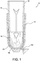
Fig. 1 is a schematic view of a prosthetic socket system according to an embodiment. -
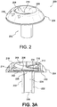
Fig. 2 is an isometric view of a valve according to an embodiment. -
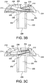
Fig. 3A is a cross-sectional view of the valve shown inFig. 2 in the closed position. -
Fig. 3B is a cross-sectional view of the valve shown inFig. 2 in the first open position. -
Fig. 3C is a cross-sectional view of the valve shown inFig. 2 in the second open position. -
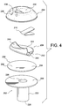
Fig. 4 is an exploded view of the valve shown inFig. 2 according to an embodiment. - A better understanding of different embodiments of the disclosure may be had from the following description read with the accompanying drawings in which like reference characters refer to like elements.
- The valve system described is configured for use with a prosthetic socket, such as lower leg prosthesis. It should be remembered, however, that the same concepts and methods described may be similarly used for other prosthetic devices and are not limited solely to the anatomical locations discussed.
- The terms "proximal" and "distal" generally refer to areas on the prosthetic socket that correspond to a location relative to where a residual limb can be inserted. For instance, the proximal end of the socket is its open end where a residual limb is first inserted into. The distal end of the socket is opposite the proximal end and includes at least part of a cavity of the socket arranged to receive a residual limb.
- As shown in
Fig. 1 , embodiments of the valve can be employed with aprosthetic socket system 10. Theprosthetic socket system 10 can include anelastomer liner sleeve 12, aprosthetic socket 14, and avalve 100. Theelastomer liner sleeve 12 can extend between aproximal end 18 and adistal end 20. Theliner sleeve 12 is typically donned on a residual limb and the limb andsleeve 12 are then inserted into asocket cavity 15 defined by theprosthetic socket 14. Thesocket 14 is typically rigid or hard to carry loads transferred from a prosthetic device attached to thesocket 14 to the residual limb and vice-versa. - The softer elastomer of the
liner sleeve 12 adheres to the skin of the residual limb frictionally to secure the limb within thesleeve 12. Theliner sleeve 12 remains within therigid socket 14 after it has been fully inserted into the distal end area of therigid socket 14 by isolating the interior of therigid socket 14 from atmosphere. Pulling forces applied to theliner sleeve 12 will cause a suction being created between the distal end of theliner sleeve 12 and the interior of thesocket 14 at the distal end area. Besides assisting with suction inside thesocket 14 so the residual limb does not fall out, theliner sleeve 12 may also provide cushioning to the limb. Using theliner sleeve 12 to provide a tight fit for the residual limb within thesocket 14 also helps to prevent air from entering the socket interior from outside of thesocket 14. - An example of a socket and method for making the same are found in
U.S. patent no. 5,885,509, granted March 23, 1999 , andU.S. patent no. 7,105,122, granted September 12, 2006 . An exemplary liner sleeve for combination with the socket is found inU.S. patent no. 6,136,039, granted October 24, 2000 ,U.S. patent no. 6,626,952, granted September 30, 2003 ,U.S. patent no. 6,485,776, granted November 26, 2002 ,U.S. patent no. 6,706,364, granted March 16, 2004 ,U.S. patent no. 7,001,563, granted February 21, 2006 , andU.S. patent no. 7,118,602, granted October 10,2006 . - If the
liner sleeve 12 provides no true air-tight seal with thesocket 14, some air will slowly enter the socket interior during use. The presence of additional air within thesocket 14 would disrupt the pressure differential between the inside of thesocket 14 and the surrounding ambient air outside thesocket 14 decreasing the suction and potentially causing the limb to become disengaged from the socket. - To further enhance isolation of the distal end area of the inside of the
socket 14 from atmosphere, aseal element 16 may be between theliner sleeve 12 and the inner surface of thesocket 14. The sealingelement 16 is configured to provide an increased sealing force between theliner sleeve 12 and thesocket 14 when theliner sleeve 12 is moved in a direction tending to withdraw it from thesocket 14. When the distal end of theliner sleeve 12 is fully inserted into thesocket 14, the sealingelement 16 further isolates the inside of thesocket 14 from ambient air outside thesocket 14 until communication is provided between the inside of the socket distal end and atmosphere. If desired, a hypobaric pressure could be created between the distal end area of theliner sleeve 12 and the distal end of thesocket 14 by attaching a pump or other device that enables evacuation of atmosphere between the sealingelement 16 and the distal end of thesocket 14. - The
socket 14 can define an aperture extending between the interior and the exterior of thesocket 14. Avalve 100 can be provided at the aperture to control fluid flow between the interior and the exterior of thesocket 14. Thevalve 100 is shown within the wall of thesocket 14 near the distal end area of thesocket 14, but may also be near other areas on thesocket 14 as desired if thevalve 100 remains in fluid communication with an interior portion of thesocket 14 where the prosthetic user's residual limb resides. - The
valve 100 can include a membrane having a flexible configuration that controls flow through thevalve 100. The membrane can have different portions that operate independently and in response to different triggers or events to more efficiently and effectively control the level of extraneous air within thesocket 14. The membrane can include a first or an attached part attached to a release element and a free part not attached to the release element. The attached part can be controlled and operated to introduce fluid or air and/or relieve pressure inside of thesocket 14 and the free part can be independently and automatically relieve a buildup of pressure inside of thesocket 14. - To prevent air flow through the
valve 100, the free part and the attached part can be both in a closed position. To allow air flow through thevalve 100, one or both of the attached part and the free part can be actuated or in an open position. The free part of the membrane is configured such that it is actuated by positive pressure inside of thesocket 14. The attached part is configured such that it actuated by movement of the release element. When the free part is actuated, the attached part is not actuated, and vice versa. This advantageously provides enhanced control of air flow through thevalve 100. - It will be appreciated that the free part is not under the influence of an opposing biasing force or member, as in the prior art. This advantageously helps to reduce air resistance over the
valve 100. This also helps to improve air flow through thevalve 100. Easy donning can be accomplished since air may be automatically and efficiently expelled as the residual limb is inserted into the socket. This is because the volume of the residual limb displaces the volume of air inside thesocket 14, forcing the free part of the membrane to actuate and forcing the remaining air out through thevalve 100. Any fluid or air expelled through thevalve 100 cannot re-enter thesocket 14 through the same channel, unless the attached part of the membrane is independently actuated by a user. The improved air flow and reduced air resistance also permits faster donning while still providing a snug fit for the residual limb. This also allows thesocket 14 to be donned in one motion or a few steps rather than having to repeatedly apply weight to evacuate thesocket 14, as in the prior art. - The membrane is arranged such that positive pressure inside the
socket 14 helps unseal the free part to expel air from thesocket 14 and negative pressure inside thesocket 14 helps seal the free part and the attached part to preserve the suspension fit of the residual limb within thesocket 14. The membrane is also configured such that the membrane forms a flow path that generally directs air traveling through thevalve 100 toward exit apertures, improving air flow and reducing air resistance. -
Figs. 2-4 illustrate an embodiment of avalve 200. Thevalve 200 can include abody 202, ahousing 204, amembrane 206 having a flexible configuration, arelease element 208, and aresilient member 210. As seen inFig. 2 , thehousing 204 may have a low-profile dome-like shape and may be attached on thebody 202. Since thehousing 204 has a low profile, there is less chance of thevalve 200 getting knocked off a socket or damaged because of bumping into foreign objects. Because of the dome-like shape, there is also less chance of thevalve 200 snagging on foreign objects. Thehousing 204 can form an interference fit, a friction fit, and/or any other suitable attachment with thebody 202. - An
interior surface 212 of thehousing 204 can define an interior cavity 214 (shown inFig. 3A ) over thebody 202. Themembrane 206,release element 208, and theresilient member 210 can be inserted in theinterior cavity 214. A opening 216 (shown inFig. 2 ) can extend between anexterior surface 218 of thehousing 204 to theinterior surface 212 of thehousing 204. Theopening 216 can provide access to therelease element 208. Theexterior surface 218 of thehousing 204 can include an ergonomic,concave recess 230 formed. Theopening 216 can be positioned in theconcave recess 230. This can help protect therelease element 208 from being caught or inadvertently bumped. This can also allow therelease element 208 to be comfortably pressed and released. It will be appreciated that while thehousing 204 is described having a dome-like shape, an opening, and concave recess, embodiments of the housing can have any suitable shape, size, and/or feature. - Referring now to
Figs. 3-4 , thebody 202 can include abase 220 and ashaft 222 connected to thebase 220. Theshaft 222 can extend generally traverse to thebase 220. Theshaft 222 can be adapted to mount thevalve 200 onto a socket. Theshaft 222 can be adapted to extend into an aperture formed through the wall of a socket for fluid communication with the interior of the socket. Alternatively, theshaft 222 can be adapted to mount thevalve 200 to a fitting and/or tube used for coupling thevalve 200 to the socket. It will be appreciated that theshaft 222 can have any shape and/or size suitable for mounting thevalve 200. - The
body 202 can define apassageway 224 extending between anopening 226 formed in the upper surface of thebase 220 and anopening 228 formed in the free end of theshaft 222. Thepassageway 224 can have a circular cross-section, an elliptical cross-section, a hexagonal cross-section, or any other suitable cross-section shape. Thepassageway 224 can have a constant diameter or a varying diameter. - Flow through the
passageway 224 is controlled by themembrane 206 inserted in theinterior cavity 214 of thehousing 204. Themembrane 206 can be a flexible disc member seated on the base 220 over theopening 226. Themembrane 206 may comprise an elastomeric material, a synthetic rubber, a fluoropolymer elastomer, and other sealing element materials and/or configurations may be employed. - The
membrane 206 can have different portions that operate independently and in response to different triggers or events to more effectively and efficiently control the level of extraneous air within a socket. Themembrane 206 can include an attachedpart 234 attached to therelease element 208 and afree part 232 not attached to therelease element 208. The attachedpart 234 of themembrane 206 can be manually controlled and operated to allow air flow through thepassageway 224. Thefree part 232 of themembrane 206 can independently and automatically to allow air flow out of thevalve 200 through thepassageway 224 in response to an increase or buildup of pressure inside of the socket. This advantageously allows thevalve 200 to more efficiently and effectively control the level of air within a socket in a wider variety of situations. - The
membrane 206 can move between a closed position (seen inFig. 3A ), wherein theopening 226 is sealed and air flow through thepassageway 224 is inhibited, and an open position, wherein theopening 226 is unsealed such that air can flow through thepassageway 224. The open position can include a first open position (seen inFig. 3B ), wherein theopening 226 is unsealed by thefree part 232 of themembrane 206 such that air can flow through thepassageway 224; and a second open position (seen inFig. 3C ), wherein theopening 226 is unsealed by the attachedpart 234 of themembrane 206 such that air can flow through thepassageway 224. - In the closed position, the
free part 232 and the attachedpart 234 of themembrane 206 are seated on thebase 220 and theopening 226 is sealed by themembrane 206 as seen inFig. 3A . Thefree part 232 can create a sealing force against the base 220 based on the material properties and/or shape of thefree part 232. The attachedpart 234 can create a sealing force against the base 220 based on the material properties and/or shape of the attachedpart 234, and a biasing force exerted on the attachedpart 234 by therelease element 208 and theresilient member 210. Themembrane 206 can be configured such that a vacuum in a socket increases the sealing force of the attachedpart 234 and/or thefree part 232 against thebase 220. - The sealing area between the
membrane 206 and the base 220 can be substantially greater than the area of theopening 226. This has the effect of improving the seal between the base 220 and themembrane 206 over theopening 226. The sealing area between themembrane 206 and the base 220 can be greater than about 1.1 times, about 1.2 times, about 1.5 times, about 2 times, about 3 times, about 4 times, or about 5 times. In other embodiments, the ratio between the sealing area of themembrane 206 and the area of theopening 226 can be larger or smaller. This advantageously allows thevalve 200 to function using only one sealing part, reducing the overall profile of thevalve 200. - In the first open position, the
free part 232 lifts away from thebase 220 and theopening 226 is unsealed as seen inFig. 3B . In the second open position, the attachedpart 234 is moved away from the base 220 by therelease element 208 and the opening is unsealed as seen inFig. 3C . - The
free part 232 and the attachedpart 234 can move themembrane 206 into the first and second open positions independently of one another and/or in response to different triggers or events. When thefree part 232 of themembrane 206 lifts away from thebase 220, air can exit the socket through thepassageway 224. When the attached part of themembrane 206 lifts away from thebase 220, air can enter or exit the socket through thepassageway 224. - The
free part 232 of themembrane 206 can automatically relieve a buildup of pressure inside of a socket. When the buildup of pressure inside of the socket exceeds the sealing force of thefree part 232, the pressure can lift thefree part 232 off of the base 220 such that theopening 226 is unsealed and air can flow from the socket through thepassageway 224. Easy donning can be accomplished since the air is automatically and expelled as the residual limb is inserted into the socket. This is because the volume of the residual limb displaces the volume of air inside the socket, forcing thefree part 232 of themembrane 206 to lift away from thebase 220, and forcing the remaining air out through thepassageway 224 of thevalve 200. - As soon as the air is expelled from the socket, the
free part 232 naturally or elastically returns to its original position on the base 220 such that any air expelled through thevalve 200 cannot re-enter the socket through thepassageway 224. The suspension fit of the residual limb within the socket can be preserved. Themembrane 206 can be configured such that the positive pressure lifts thefree part 232 away from the base 220 but not the attachedpart 234. - The
valve 200 can permit expulsion of the air through apertures 236 (seen inFig. 2 ) formed by thehousing 204, with the air entering theopening 228 in theshaft 222, passing through thepassageway 224, theopening 226, theinterior cavity 214 of thehousing 204, and exiting theapertures 236. This arrangement easily lets air expel through thevalve 200. As seen inFig. 3B , when thefree part 232 of themembrane 206 is rotated away from thebase 220, the shape of the bottom surface of thefree part 232 above theopening 226 can form a flow path that redirects the air exiting theopening 226 toward theapertures 236. This allows the air to move more smoothly and directly out of thevalve 200, reducing air resistance. - The
free part 232 of themembrane 206 is arranged such that it is not under the influence of a distinct biasing force or member, as in the prior art. For instance, the pressure buildup can easily swing or lift thefree part 232 away from thebase 220 without having to overcome an opposing biasing member pushing thefree part 232 back toward thebase 220. This advantageously helps to reduce air resistance and to improve air flow through thevalve 100. - The arrangement of the
free part 232 can also provide partial suction created naturally during ambulation, improving suspension. For instance, air may be drawn into the interior of conventional sockets during the repeating phases of a normal gait cycle. The repetitive motions displayed between the stance and swing phases of walking generate a pumping and pistoning effect within the socket which draws in air and creates positive pressure. To combat this problem, thefree part 232 can function to expel the air from the region between the socket interior and the liner-sheathed residual limb. The pressure within this space decreases as air is expelled correspondingly increasing the suction available to hold a prosthetic device to the residual limb. - The point at which the build of pressure inside of a socket triggers or lifts the
free part 232 off of the base 220 can be any suitable pressure and/or can be customized based on the individual needs of the user. This pressure can be selected or set by a user, a clinician, or a medical professional. - The attached
part 234 of themembrane 206 can be operated and controlled independently of thefree part 232 to introduce and/or relieve pressure inside of a socket. As seen inFig. 3C , when therelease element 208 is moved to a release position, therelease element 208 can lift the attachedpart 234 off of the base 220 such that theopening 226 is unsealed and air can flow from the socket through thepassageway 224. When the button is released, theresilient member 210 can return therelease element 208 to its normal position, which causes the attachedpart 234 to reseal theopening 226 and inhibits air flow through thepassageway 224. Themembrane 206 can be configured such that when therelease element 208 lifts the attachedpart 234 away from thebase 220, thefree part 232 is not lifted from thebase 220. Themembrane 206 can be configured such that when therelease element 208 lifts the attachedpart 234 away from thebase 220, at least a portion of thefree part 232 is lifted from thebase 220. - Because operation of the attached
part 234 is not configured to depend on the pressure inside of the socket, the attachedpart 234 can be actuated in negative pressure and/or positive pressure environments. If the attachedpart 234 is actuated when there is a pressure buildup in a socket, the air inside of the socket can escape through thevalve 200. If the attachedpart 234 is actuated when there is a vacuum in a socket, outside air can be drawn into the socket through thevalve 200. This advantageously helps break the suction between the liner-sheathed residual limb and the socket, allowing the user to quickly and easily remove the socket. - The attached
part 234 of themembrane 206 is connected to therelease element 208 in such a way that the attachedpart 234 can cover at least a portion of theopening 226 when thefree part 232 moves themembrane 206 to the first open position. Thefree part 232 is configured such that at least a portion of thefree part 232 can cover at least a portion of theopening 226 when the attachedpart 234 moves the membrane to the second open position. This advantageously allows the attachedpart 234 and thefree part 232 to independently unseal theopening 226. - As best shown in
Fig. 4 , therelease element 208 can be pivotally connected to thehousing 204. Thehousing 204 can include a pair of pivot arm receiving recesses 238. Pivotarms 240 of therelease element 208 can be positioned within therecesses 238 and pivotally connected to thehousing 204. Therelease element 208 is rotatable about an axis extending through thepivot arms 240 between a normal position, in which aflat engagement portion 242 of therelease element 208, which is connected to the attachedpart 234 of themembrane 206, holds attachedpart 234 against thebase 220, and a release position, wherein theengagement portion 242 rotates away from thebase 220 and lifts the attachedportion 234 off of thebase 220, thus manually unsealing theopening 226. The distance therelease element 208 moves can correspond to how large of a space or flow area is formed between theattached part 234 and theopening 226. For instance, if a user wants to expel only a small amount of air from a socket, the user can move therelease element 208 only a small distance such that a smaller flow area is formed between theattached part 234 and theopening 226. If a user wants to expel more air from a socket, the user can move the release element 208 a greater distance. Therelease element 208 can include aconcave recess 246 that corresponds to theconcave recess 230 of thehousing 204. Therelease element 208 can be a release element or any other suitable type of release element. - The
release element 208 can be biased toward the normal position. For instance, theresilient member 210 can be positioned between theinterior surface 212 of thehousing 204 and a bearingportion 244 on the upper side of therelease element 208. Theresilient member 210 can comprise a v-type spring including a first arm engaging the bearingportion 244 and a second arm engaging thehousing 204. Theresilient member 210 can be compressed between therelease element 208 and thehousing 204 and stored mechanical energy in theresilient member 210 can force therelease element 208 toward the normal position. While a v-type spring is described, it will be appreciated that the resilient member can comprise any suitable member to bias therelease element 208 toward the normal position, such as, for example a torsion spring or bar or any other suitable member. - Moving the
release element 208 to the release position can let air into a socket so the socket can be doffed. The air enters theapertures 236 and channels through thefluid passageway 224 to introduce air into the socket. This advantageously helps break the suction between the liner-sheathed residual limb and the socket, allowing the user to quickly and easily remove the socket. Moving therelease element 208 to the release position can also let air out of a socket so the socket can be donned. This allows a user to manually expel air from a socket so the socket can be donned. - It will be appreciated that the
valve 200 is to be exemplary only, any valve is possible. While the membrane is shown comprising a disc-like member, in other embodiments, the membrane may comprise a Belleville washer, a membrane having a flexible and rigid section, a diaphragm valve, a saddle type valve, a straight through valve, a check valve, a relief valve, or any other suitable sealing element. It should be appreciated that many variations of the release element having different shapes and sizes can be used for manipulating the membrane. Although such variations may differ in form, they perform substantially similar functions. In other embodiments, the valve may include more than one passageway and over two openings. In yet other embodiments, the housing may have a cylindrical or other suitable shape.
Claims (15)
- A valve (200) for a prosthetic socket (14) defining a socket cavity (15) comprising:a body (202) defining a first opening (226), a second opening (228) adapted to be in fluid communication with the socket cavity (15), and a passageway (224) formed between the first opening (226) and the second opening (228); anda membrane (206) flexibly seated on the body (202) over the first opening (226) and movable between a closed position in which the first opening (226) is sealed by the membrane (206) such that fluid communication between the first opening (226) and the second opening (228) is inhibited, and an open position in which the first opening (226) is unsealed such that fluid can flow through the passageway (224),characterized in that the membrane (206) includes a first part (234) connected to a release element (208) and operable to move the membrane (206) between the open position and the closed position, and a free part (232) operable independent of the first part (234) to move the membrane (206) between the open position and the closed position.
- The valve (200) of claim 1, characterized in that the first part (234) moves the membrane (206) to the open position in response to movement of the release element (208), and the free part (232) moves the membrane (206) to the open position in response to a buildup of pressure in the socket cavity (15).
- The valve (200) of any one of the preceding claims, characterized in that the release element (208) is movable between a normal position arranged to compress the first part (234) against the body (202), and a release position arranged to lift the first part (234) away from the body (202) to unseal the first opening (226).
- The valve (200) of claim 3, characterized in further comprising a housing (204) secured on the body (202) over the membrane (206), and a resilient member (210) located between the housing (204) and the release element (208) biasing the release element (208) toward the normal position.
- The valve (200) of any one of the preceding claims, characterized in that at least a portion of the first part (234) covers at least a portion of the first opening (226) when the free part (232) moves the membrane (206) to the open position.
- The valve (200) of any one of the preceding claims, characterized in that at least a portion of the free part (232) covers at least a portion of the first opening (226) when the first part (234) moves the membrane (206) to the open position.
- The valve (200) of any one of the preceding claims, characterized in that the membrane (206) comprises an elastomeric disc.
- The valve (200) of any one of the preceding claims, characterized in that a pressure build up in the prosthetic socket (14) lifts the free part (232) without unsealing the first part (234) of the membrane (206) away from the first opening (226).
- The valve (200) of any one of claims 1-3 or any one of claims 5-8 when being dependent on any one of claims 1-3, characterized in further comprising a housing (204) secured on the body (202) over the membrane (206), and pivotally connected to the release element (208).
- The valve of claim 9, characterized in that the housing (204) defines an opening (216) arranged to accommodate a portion of the release element (210).
- The valve of claim 10, characterized in that an exterior surface (218) of the housing (204) defines a concave recess (230) thereon.
- The valve of claim 11, characterized in that the opening (216) is defined in the concave recess (230).
- The valve of claim 12, characterized in that the release element (210) defines a second concave recess (246) substantially corresponding to the concave recess (230) of the housing (204).
- The valve of claim 9, characterized in that the housing (204) defines an interior cavity (214) and a plurality of through apertures (236) in fluid communication with the interior cavity (214), the release element (210) substantially situated within the interior cavity (214).
- The valve of claim 14, characterized in that an engagement portion (242) of the release element (210) directs air through at least one of the through apertures (236) when the release element (210) is in the release position.
Applications Claiming Priority (2)
| Application Number | Priority Date | Filing Date | Title |
|---|---|---|---|
| US201461955880P | 2014-03-20 | 2014-03-20 | |
| PCT/US2015/020657 WO2015142692A1 (en) | 2014-03-20 | 2015-03-16 | Valve for prosthetic device |
Publications (2)
| Publication Number | Publication Date |
|---|---|
| EP3125830A1 EP3125830A1 (en) | 2017-02-08 |
| EP3125830B1 true EP3125830B1 (en) | 2018-02-28 |
Family
ID=52875246
Family Applications (1)
| Application Number | Title | Priority Date | Filing Date |
|---|---|---|---|
| EP15712506.3A Active EP3125830B1 (en) | 2014-03-20 | 2015-03-16 | Valve for prosthetic device |
Country Status (3)
| Country | Link |
|---|---|
| US (1) | US9474636B2 (en) |
| EP (1) | EP3125830B1 (en) |
| WO (1) | WO2015142692A1 (en) |
Families Citing this family (3)
| Publication number | Priority date | Publication date | Assignee | Title |
|---|---|---|---|---|
| US10842653B2 (en) | 2007-09-19 | 2020-11-24 | Ability Dynamics, Llc | Vacuum system for a prosthetic foot |
| AU2013256565B2 (en) * | 2012-04-30 | 2015-12-03 | Ossur Hf | Prosthetic device, system and method for increasing vacuum attachment |
| FR3051353B1 (en) | 2016-05-18 | 2021-11-05 | Chabloz Composants | VALVE FOR PROSTHESIS SOCKET |
Family Cites Families (19)
| Publication number | Priority date | Publication date | Assignee | Title |
|---|---|---|---|---|
| AT164884B (en) * | 1946-04-30 | 1949-12-27 | Wilhelm Kleidorfer | Compensation valve for prostheses |
| US2530285A (en) | 1947-12-11 | 1950-11-14 | John G Catranis | Artificial leg |
| US2569790A (en) * | 1950-06-30 | 1951-10-02 | White | Valve for suction socket prosthesis |
| US4595172A (en) | 1985-03-29 | 1986-06-17 | Gene Henderson | Vent valves for prosthetic devices |
| US4655779A (en) | 1985-10-31 | 1987-04-07 | Janowiak Christopher S | Air system prosthesis for amputees |
| BR9710873A (en) * | 1996-07-19 | 2000-01-11 | Robert B Chaffee | Valve for inflatable objects. |
| US5885509A (en) | 1996-10-30 | 1999-03-23 | Ossur Hf | Apparatus and process for forming prosthetic socket |
| DE19651951C2 (en) | 1996-12-16 | 2002-06-27 | Adeva Medical Ges Fuer Entwick | Shunt valve |
| US6136039A (en) | 1997-05-06 | 2000-10-24 | Ossur Hf | Dual durometer silicone liner for prosthesis |
| ATE433310T1 (en) | 2000-03-14 | 2009-06-15 | Ossur Hf | ELASTIC COMPOSITE MATERIAL |
| JP2003526424A (en) | 2000-03-15 | 2003-09-09 | オスール・エイチエフ | Apparatus and method for making a prosthetic suction sleeve |
| US6613096B1 (en) | 2002-04-05 | 2003-09-02 | Raymond A. Shirvis | Prosthetic pressure relief valve system |
| US7105122B2 (en) | 2002-10-08 | 2006-09-12 | Ossur Hf | Prosthesis socket direct casting device having multiple compression chambers |
| EP2436344B1 (en) | 2004-05-28 | 2014-12-17 | Össur HF | Prosthetic or orthotic sleeve having external surface peripheral profiles |
| US9408724B2 (en) * | 2005-09-24 | 2016-08-09 | Coyote Design And Manufacturing, Inc. | Air valve for external prosthesis |
| US7993413B2 (en) | 2005-09-24 | 2011-08-09 | Matt Perkins | Valve system for prosthetics |
| FR2903294B1 (en) | 2006-07-06 | 2009-02-13 | Pierre Chabloz | JOINING DEVICE BY SEPARATELY SEALED BETWEEN A PROSTHESIS AND A SLEEVE INSTALLED ON THE LEFT OF AN AMPUTE MEMBER, AND PROSTHESIS EQUIPPED WITH SUCH A JUNCTION DEVICE |
| US8382852B2 (en) | 2008-06-10 | 2013-02-26 | Alps Intellectual Property Management, Llc | Prosthetic liner with perspiration elimination mechanism |
| US8113235B2 (en) | 2008-10-03 | 2012-02-14 | David Robert Bogue | Apparatus and methods for facilitating prosthesis donning, doffing, retention, and fit |
-
2015
- 2015-03-16 EP EP15712506.3A patent/EP3125830B1/en active Active
- 2015-03-16 US US14/658,338 patent/US9474636B2/en active Active
- 2015-03-16 WO PCT/US2015/020657 patent/WO2015142692A1/en active Application Filing
Also Published As
| Publication number | Publication date |
|---|---|
| WO2015142692A1 (en) | 2015-09-24 |
| EP3125830A1 (en) | 2017-02-08 |
| US20150265433A1 (en) | 2015-09-24 |
| US9474636B2 (en) | 2016-10-25 |
Similar Documents
| Publication | Publication Date | Title |
|---|---|---|
| US7632315B2 (en) | Vacuum chamber socket system | |
| US9155636B1 (en) | Prosthetic socket liner | |
| EP3164100B1 (en) | Pump mechanism for vacuum suspension system | |
| EP3125830B1 (en) | Valve for prosthetic device | |
| US9820873B2 (en) | Vacuum suspension system | |
| US8080065B2 (en) | Vacuum assisted prosthetic sleeve and socket utilizing a double membrane liner | |
| US4979944A (en) | Surgical vacuum evacuation device | |
| US8113235B2 (en) | Apparatus and methods for facilitating prosthesis donning, doffing, retention, and fit | |
| US6361568B1 (en) | Prosthetic sleeve with air outlet valve | |
| US8211187B2 (en) | Elevated vacuum locking system | |
| US20070112440A1 (en) | Valve system for prosthesis | |
| US11806255B2 (en) | Multi-chamber vacuum pump | |
| US9161848B2 (en) | Systems and methods for prosthetic suspension system | |
| EP3016619B1 (en) | Prosthetic pin locking mechanism with vacuum tunnels | |
| EP0119231A1 (en) | Artificial limb valve | |
| CN115944792A (en) | Pressure regulated airway assist device | |
| EP3703626B1 (en) | Prosthetic socket system | |
| US11324612B2 (en) | Breathable residual-limb socket system | |
| US4595172A (en) | Vent valves for prosthetic devices | |
| US11806254B2 (en) | Prosthesis suspension liner sealing cap and prosthesis suspension system |
Legal Events
| Date | Code | Title | Description |
|---|---|---|---|
| STAA | Information on the status of an ep patent application or granted ep patent |
Free format text: STATUS: THE INTERNATIONAL PUBLICATION HAS BEEN MADE |
|
| PUAI | Public reference made under article 153(3) epc to a published international application that has entered the european phase |
Free format text: ORIGINAL CODE: 0009012 |
|
| STAA | Information on the status of an ep patent application or granted ep patent |
Free format text: STATUS: REQUEST FOR EXAMINATION WAS MADE |
|
| 17P | Request for examination filed |
Effective date: 20161020 |
|
| AK | Designated contracting states |
Kind code of ref document: A1 Designated state(s): AL AT BE BG CH CY CZ DE DK EE ES FI FR GB GR HR HU IE IS IT LI LT LU LV MC MK MT NL NO PL PT RO RS SE SI SK SM TR |
|
| AX | Request for extension of the european patent |
Extension state: BA ME |
|
| DAV | Request for validation of the european patent (deleted) | ||
| DAX | Request for extension of the european patent (deleted) | ||
| GRAP | Despatch of communication of intention to grant a patent |
Free format text: ORIGINAL CODE: EPIDOSNIGR1 |
|
| STAA | Information on the status of an ep patent application or granted ep patent |
Free format text: STATUS: GRANT OF PATENT IS INTENDED |
|
| INTG | Intention to grant announced |
Effective date: 20171018 |
|
| GRAS | Grant fee paid |
Free format text: ORIGINAL CODE: EPIDOSNIGR3 |
|
| GRAA | (expected) grant |
Free format text: ORIGINAL CODE: 0009210 |
|
| STAA | Information on the status of an ep patent application or granted ep patent |
Free format text: STATUS: THE PATENT HAS BEEN GRANTED |
|
| REG | Reference to a national code |
Ref country code: FR Ref legal event code: PLFP Year of fee payment: 4 |
|
| AK | Designated contracting states |
Kind code of ref document: B1 Designated state(s): AL AT BE BG CH CY CZ DE DK EE ES FI FR GB GR HR HU IE IS IT LI LT LU LV MC MK MT NL NO PL PT RO RS SE SI SK SM TR |
|
| REG | Reference to a national code |
Ref country code: GB Ref legal event code: FG4D Ref country code: CH Ref legal event code: EP |
|
| REG | Reference to a national code |
Ref country code: AT Ref legal event code: REF Ref document number: 973307 Country of ref document: AT Kind code of ref document: T Effective date: 20180315 |
|
| REG | Reference to a national code |
Ref country code: IE Ref legal event code: FG4D |
|
| REG | Reference to a national code |
Ref country code: DE Ref legal event code: R096 Ref document number: 602015008381 Country of ref document: DE |
|
| REG | Reference to a national code |
Ref country code: NL Ref legal event code: MP Effective date: 20180228 |
|
| REG | Reference to a national code |
Ref country code: LT Ref legal event code: MG4D |
|
| REG | Reference to a national code |
Ref country code: AT Ref legal event code: MK05 Ref document number: 973307 Country of ref document: AT Kind code of ref document: T Effective date: 20180228 |
|
| PG25 | Lapsed in a contracting state [announced via postgrant information from national office to epo] |
Ref country code: LT Free format text: LAPSE BECAUSE OF FAILURE TO SUBMIT A TRANSLATION OF THE DESCRIPTION OR TO PAY THE FEE WITHIN THE PRESCRIBED TIME-LIMIT Effective date: 20180228 Ref country code: CY Free format text: LAPSE BECAUSE OF FAILURE TO SUBMIT A TRANSLATION OF THE DESCRIPTION OR TO PAY THE FEE WITHIN THE PRESCRIBED TIME-LIMIT Effective date: 20180228 Ref country code: HR Free format text: LAPSE BECAUSE OF FAILURE TO SUBMIT A TRANSLATION OF THE DESCRIPTION OR TO PAY THE FEE WITHIN THE PRESCRIBED TIME-LIMIT Effective date: 20180228 Ref country code: FI Free format text: LAPSE BECAUSE OF FAILURE TO SUBMIT A TRANSLATION OF THE DESCRIPTION OR TO PAY THE FEE WITHIN THE PRESCRIBED TIME-LIMIT Effective date: 20180228 Ref country code: NO Free format text: LAPSE BECAUSE OF FAILURE TO SUBMIT A TRANSLATION OF THE DESCRIPTION OR TO PAY THE FEE WITHIN THE PRESCRIBED TIME-LIMIT Effective date: 20180528 Ref country code: ES Free format text: LAPSE BECAUSE OF FAILURE TO SUBMIT A TRANSLATION OF THE DESCRIPTION OR TO PAY THE FEE WITHIN THE PRESCRIBED TIME-LIMIT Effective date: 20180228 Ref country code: NL Free format text: LAPSE BECAUSE OF FAILURE TO SUBMIT A TRANSLATION OF THE DESCRIPTION OR TO PAY THE FEE WITHIN THE PRESCRIBED TIME-LIMIT Effective date: 20180228 |
|
| PG25 | Lapsed in a contracting state [announced via postgrant information from national office to epo] |
Ref country code: RS Free format text: LAPSE BECAUSE OF FAILURE TO SUBMIT A TRANSLATION OF THE DESCRIPTION OR TO PAY THE FEE WITHIN THE PRESCRIBED TIME-LIMIT Effective date: 20180228 Ref country code: AT Free format text: LAPSE BECAUSE OF FAILURE TO SUBMIT A TRANSLATION OF THE DESCRIPTION OR TO PAY THE FEE WITHIN THE PRESCRIBED TIME-LIMIT Effective date: 20180228 Ref country code: BG Free format text: LAPSE BECAUSE OF FAILURE TO SUBMIT A TRANSLATION OF THE DESCRIPTION OR TO PAY THE FEE WITHIN THE PRESCRIBED TIME-LIMIT Effective date: 20180528 Ref country code: GR Free format text: LAPSE BECAUSE OF FAILURE TO SUBMIT A TRANSLATION OF THE DESCRIPTION OR TO PAY THE FEE WITHIN THE PRESCRIBED TIME-LIMIT Effective date: 20180529 Ref country code: SE Free format text: LAPSE BECAUSE OF FAILURE TO SUBMIT A TRANSLATION OF THE DESCRIPTION OR TO PAY THE FEE WITHIN THE PRESCRIBED TIME-LIMIT Effective date: 20180228 Ref country code: LV Free format text: LAPSE BECAUSE OF FAILURE TO SUBMIT A TRANSLATION OF THE DESCRIPTION OR TO PAY THE FEE WITHIN THE PRESCRIBED TIME-LIMIT Effective date: 20180228 |
|
| PG25 | Lapsed in a contracting state [announced via postgrant information from national office to epo] |
Ref country code: AL Free format text: LAPSE BECAUSE OF FAILURE TO SUBMIT A TRANSLATION OF THE DESCRIPTION OR TO PAY THE FEE WITHIN THE PRESCRIBED TIME-LIMIT Effective date: 20180228 Ref country code: EE Free format text: LAPSE BECAUSE OF FAILURE TO SUBMIT A TRANSLATION OF THE DESCRIPTION OR TO PAY THE FEE WITHIN THE PRESCRIBED TIME-LIMIT Effective date: 20180228 Ref country code: IT Free format text: LAPSE BECAUSE OF FAILURE TO SUBMIT A TRANSLATION OF THE DESCRIPTION OR TO PAY THE FEE WITHIN THE PRESCRIBED TIME-LIMIT Effective date: 20180228 Ref country code: RO Free format text: LAPSE BECAUSE OF FAILURE TO SUBMIT A TRANSLATION OF THE DESCRIPTION OR TO PAY THE FEE WITHIN THE PRESCRIBED TIME-LIMIT Effective date: 20180228 Ref country code: PL Free format text: LAPSE BECAUSE OF FAILURE TO SUBMIT A TRANSLATION OF THE DESCRIPTION OR TO PAY THE FEE WITHIN THE PRESCRIBED TIME-LIMIT Effective date: 20180228 |
|
| REG | Reference to a national code |
Ref country code: CH Ref legal event code: PL |
|
| REG | Reference to a national code |
Ref country code: DE Ref legal event code: R097 Ref document number: 602015008381 Country of ref document: DE |
|
| PG25 | Lapsed in a contracting state [announced via postgrant information from national office to epo] |
Ref country code: SK Free format text: LAPSE BECAUSE OF FAILURE TO SUBMIT A TRANSLATION OF THE DESCRIPTION OR TO PAY THE FEE WITHIN THE PRESCRIBED TIME-LIMIT Effective date: 20180228 Ref country code: CZ Free format text: LAPSE BECAUSE OF FAILURE TO SUBMIT A TRANSLATION OF THE DESCRIPTION OR TO PAY THE FEE WITHIN THE PRESCRIBED TIME-LIMIT Effective date: 20180228 Ref country code: DK Free format text: LAPSE BECAUSE OF FAILURE TO SUBMIT A TRANSLATION OF THE DESCRIPTION OR TO PAY THE FEE WITHIN THE PRESCRIBED TIME-LIMIT Effective date: 20180228 Ref country code: MC Free format text: LAPSE BECAUSE OF FAILURE TO SUBMIT A TRANSLATION OF THE DESCRIPTION OR TO PAY THE FEE WITHIN THE PRESCRIBED TIME-LIMIT Effective date: 20180228 Ref country code: SM Free format text: LAPSE BECAUSE OF FAILURE TO SUBMIT A TRANSLATION OF THE DESCRIPTION OR TO PAY THE FEE WITHIN THE PRESCRIBED TIME-LIMIT Effective date: 20180228 |
|
| REG | Reference to a national code |
Ref country code: BE Ref legal event code: MM Effective date: 20180331 |
|
| REG | Reference to a national code |
Ref country code: IE Ref legal event code: MM4A |
|
| PG25 | Lapsed in a contracting state [announced via postgrant information from national office to epo] |
Ref country code: LU Free format text: LAPSE BECAUSE OF NON-PAYMENT OF DUE FEES Effective date: 20180316 |
|
| PLBE | No opposition filed within time limit |
Free format text: ORIGINAL CODE: 0009261 |
|
| STAA | Information on the status of an ep patent application or granted ep patent |
Free format text: STATUS: NO OPPOSITION FILED WITHIN TIME LIMIT |
|
| PG25 | Lapsed in a contracting state [announced via postgrant information from national office to epo] |
Ref country code: IE Free format text: LAPSE BECAUSE OF NON-PAYMENT OF DUE FEES Effective date: 20180316 |
|
| 26N | No opposition filed |
Effective date: 20181129 |
|
| PG25 | Lapsed in a contracting state [announced via postgrant information from national office to epo] |
Ref country code: LI Free format text: LAPSE BECAUSE OF NON-PAYMENT OF DUE FEES Effective date: 20180331 Ref country code: SI Free format text: LAPSE BECAUSE OF FAILURE TO SUBMIT A TRANSLATION OF THE DESCRIPTION OR TO PAY THE FEE WITHIN THE PRESCRIBED TIME-LIMIT Effective date: 20180228 Ref country code: CH Free format text: LAPSE BECAUSE OF NON-PAYMENT OF DUE FEES Effective date: 20180331 Ref country code: BE Free format text: LAPSE BECAUSE OF NON-PAYMENT OF DUE FEES Effective date: 20180331 |
|
| PG25 | Lapsed in a contracting state [announced via postgrant information from national office to epo] |
Ref country code: MT Free format text: LAPSE BECAUSE OF NON-PAYMENT OF DUE FEES Effective date: 20180316 |
|
| PG25 | Lapsed in a contracting state [announced via postgrant information from national office to epo] |
Ref country code: TR Free format text: LAPSE BECAUSE OF FAILURE TO SUBMIT A TRANSLATION OF THE DESCRIPTION OR TO PAY THE FEE WITHIN THE PRESCRIBED TIME-LIMIT Effective date: 20180228 |
|
| PG25 | Lapsed in a contracting state [announced via postgrant information from national office to epo] |
Ref country code: PT Free format text: LAPSE BECAUSE OF FAILURE TO SUBMIT A TRANSLATION OF THE DESCRIPTION OR TO PAY THE FEE WITHIN THE PRESCRIBED TIME-LIMIT Effective date: 20180228 |
|
| PG25 | Lapsed in a contracting state [announced via postgrant information from national office to epo] |
Ref country code: HU Free format text: LAPSE BECAUSE OF FAILURE TO SUBMIT A TRANSLATION OF THE DESCRIPTION OR TO PAY THE FEE WITHIN THE PRESCRIBED TIME-LIMIT; INVALID AB INITIO Effective date: 20150316 Ref country code: MK Free format text: LAPSE BECAUSE OF NON-PAYMENT OF DUE FEES Effective date: 20180228 |
|
| PG25 | Lapsed in a contracting state [announced via postgrant information from national office to epo] |
Ref country code: IS Free format text: LAPSE BECAUSE OF FAILURE TO SUBMIT A TRANSLATION OF THE DESCRIPTION OR TO PAY THE FEE WITHIN THE PRESCRIBED TIME-LIMIT Effective date: 20180628 |
|
| P01 | Opt-out of the competence of the unified patent court (upc) registered |
Effective date: 20230516 |
|
| PGFP | Annual fee paid to national office [announced via postgrant information from national office to epo] |
Ref country code: DE Payment date: 20240319 Year of fee payment: 10 Ref country code: GB Payment date: 20240318 Year of fee payment: 10 |
|
| PGFP | Annual fee paid to national office [announced via postgrant information from national office to epo] |
Ref country code: FR Payment date: 20240315 Year of fee payment: 10 |