EP3125806B1 - Quantitative three-dimensional imaging of surgical scenes - Google Patents
Quantitative three-dimensional imaging of surgical scenes Download PDFInfo
- Publication number
- EP3125806B1 EP3125806B1 EP15768409.3A EP15768409A EP3125806B1 EP 3125806 B1 EP3125806 B1 EP 3125806B1 EP 15768409 A EP15768409 A EP 15768409A EP 3125806 B1 EP3125806 B1 EP 3125806B1
- Authority
- EP
- European Patent Office
- Prior art keywords
- sensors
- image
- fov
- pixels
- view
- Prior art date
- Legal status (The legal status is an assumption and is not a legal conclusion. Google has not performed a legal analysis and makes no representation as to the accuracy of the status listed.)
- Active
Links
- 238000003384 imaging method Methods 0.000 title description 20
- 238000000034 method Methods 0.000 claims description 48
- 230000008569 process Effects 0.000 claims description 36
- 230000004044 response Effects 0.000 claims description 26
- 238000003491 array Methods 0.000 claims description 7
- 238000010586 diagram Methods 0.000 description 15
- 238000009472 formulation Methods 0.000 description 8
- 239000003550 marker Substances 0.000 description 8
- 239000000203 mixture Substances 0.000 description 8
- 238000001356 surgical procedure Methods 0.000 description 7
- 230000006870 function Effects 0.000 description 5
- 238000001839 endoscopy Methods 0.000 description 4
- 230000007246 mechanism Effects 0.000 description 4
- 230000003287 optical effect Effects 0.000 description 4
- 238000004590 computer program Methods 0.000 description 3
- 230000000694 effects Effects 0.000 description 3
- 230000014509 gene expression Effects 0.000 description 3
- 238000005286 illumination Methods 0.000 description 3
- 238000012978 minimally invasive surgical procedure Methods 0.000 description 3
- 238000012545 processing Methods 0.000 description 3
- 230000000007 visual effect Effects 0.000 description 3
- 210000003484 anatomy Anatomy 0.000 description 2
- 230000015572 biosynthetic process Effects 0.000 description 2
- 230000008859 change Effects 0.000 description 2
- 230000001934 delay Effects 0.000 description 2
- 238000006073 displacement reaction Methods 0.000 description 2
- 230000004927 fusion Effects 0.000 description 2
- 230000001788 irregular Effects 0.000 description 2
- 238000012804 iterative process Methods 0.000 description 2
- 238000004519 manufacturing process Methods 0.000 description 2
- 238000012986 modification Methods 0.000 description 2
- 230000004048 modification Effects 0.000 description 2
- 210000000056 organ Anatomy 0.000 description 2
- 238000000513 principal component analysis Methods 0.000 description 2
- 238000001228 spectrum Methods 0.000 description 2
- 238000003860 storage Methods 0.000 description 2
- 238000003786 synthesis reaction Methods 0.000 description 2
- 101100507312 Invertebrate iridescent virus 6 EF1 gene Proteins 0.000 description 1
- XUIMIQQOPSSXEZ-UHFFFAOYSA-N Silicon Chemical compound [Si] XUIMIQQOPSSXEZ-UHFFFAOYSA-N 0.000 description 1
- 238000000429 assembly Methods 0.000 description 1
- 230000000712 assembly Effects 0.000 description 1
- 230000008901 benefit Effects 0.000 description 1
- 230000004397 blinking Effects 0.000 description 1
- 238000009125 cardiac resynchronization therapy Methods 0.000 description 1
- 239000003086 colorant Substances 0.000 description 1
- 230000000295 complement effect Effects 0.000 description 1
- 239000000356 contaminant Substances 0.000 description 1
- 238000005314 correlation function Methods 0.000 description 1
- 238000013480 data collection Methods 0.000 description 1
- 230000001419 dependent effect Effects 0.000 description 1
- 238000003745 diagnosis Methods 0.000 description 1
- 238000003708 edge detection Methods 0.000 description 1
- 238000002674 endoscopic surgery Methods 0.000 description 1
- 239000011521 glass Substances 0.000 description 1
- 238000010191 image analysis Methods 0.000 description 1
- 239000007943 implant Substances 0.000 description 1
- 239000004973 liquid crystal related substance Substances 0.000 description 1
- 238000013507 mapping Methods 0.000 description 1
- 239000011159 matrix material Substances 0.000 description 1
- 238000012544 monitoring process Methods 0.000 description 1
- 150000004767 nitrides Chemical class 0.000 description 1
- 230000008447 perception Effects 0.000 description 1
- 230000002093 peripheral effect Effects 0.000 description 1
- 230000002250 progressing effect Effects 0.000 description 1
- 230000001681 protective effect Effects 0.000 description 1
- 238000012552 review Methods 0.000 description 1
- 238000002432 robotic surgery Methods 0.000 description 1
- 238000005070 sampling Methods 0.000 description 1
- 239000004065 semiconductor Substances 0.000 description 1
- 238000000926 separation method Methods 0.000 description 1
- 229910052710 silicon Inorganic materials 0.000 description 1
- 239000010703 silicon Substances 0.000 description 1
- 238000004513 sizing Methods 0.000 description 1
- 239000013589 supplement Substances 0.000 description 1
- 238000012876 topography Methods 0.000 description 1
- 230000009466 transformation Effects 0.000 description 1
- 238000000844 transformation Methods 0.000 description 1
- 238000012800 visualization Methods 0.000 description 1
Images


Classifications
-
- H—ELECTRICITY
- H04—ELECTRIC COMMUNICATION TECHNIQUE
- H04N—PICTORIAL COMMUNICATION, e.g. TELEVISION
- H04N13/00—Stereoscopic video systems; Multi-view video systems; Details thereof
- H04N13/20—Image signal generators
- H04N13/204—Image signal generators using stereoscopic image cameras
- H04N13/25—Image signal generators using stereoscopic image cameras using two or more image sensors with different characteristics other than in their location or field of view, e.g. having different resolutions or colour pickup characteristics; using image signals from one sensor to control the characteristics of another sensor
-
- A—HUMAN NECESSITIES
- A61—MEDICAL OR VETERINARY SCIENCE; HYGIENE
- A61B—DIAGNOSIS; SURGERY; IDENTIFICATION
- A61B1/00—Instruments for performing medical examinations of the interior of cavities or tubes of the body by visual or photographical inspection, e.g. endoscopes; Illuminating arrangements therefor
- A61B1/00002—Operational features of endoscopes
- A61B1/00004—Operational features of endoscopes characterised by electronic signal processing
- A61B1/00009—Operational features of endoscopes characterised by electronic signal processing of image signals during a use of endoscope
-
- A—HUMAN NECESSITIES
- A61—MEDICAL OR VETERINARY SCIENCE; HYGIENE
- A61B—DIAGNOSIS; SURGERY; IDENTIFICATION
- A61B1/00—Instruments for performing medical examinations of the interior of cavities or tubes of the body by visual or photographical inspection, e.g. endoscopes; Illuminating arrangements therefor
- A61B1/00163—Optical arrangements
- A61B1/00194—Optical arrangements adapted for three-dimensional imaging
-
- A—HUMAN NECESSITIES
- A61—MEDICAL OR VETERINARY SCIENCE; HYGIENE
- A61B—DIAGNOSIS; SURGERY; IDENTIFICATION
- A61B1/00—Instruments for performing medical examinations of the interior of cavities or tubes of the body by visual or photographical inspection, e.g. endoscopes; Illuminating arrangements therefor
- A61B1/04—Instruments for performing medical examinations of the interior of cavities or tubes of the body by visual or photographical inspection, e.g. endoscopes; Illuminating arrangements therefor combined with photographic or television appliances
- A61B1/05—Instruments for performing medical examinations of the interior of cavities or tubes of the body by visual or photographical inspection, e.g. endoscopes; Illuminating arrangements therefor combined with photographic or television appliances characterised by the image sensor, e.g. camera, being in the distal end portion
- A61B1/051—Details of CCD assembly
-
- A—HUMAN NECESSITIES
- A61—MEDICAL OR VETERINARY SCIENCE; HYGIENE
- A61B—DIAGNOSIS; SURGERY; IDENTIFICATION
- A61B1/00—Instruments for performing medical examinations of the interior of cavities or tubes of the body by visual or photographical inspection, e.g. endoscopes; Illuminating arrangements therefor
- A61B1/06—Instruments for performing medical examinations of the interior of cavities or tubes of the body by visual or photographical inspection, e.g. endoscopes; Illuminating arrangements therefor with illuminating arrangements
-
- A—HUMAN NECESSITIES
- A61—MEDICAL OR VETERINARY SCIENCE; HYGIENE
- A61B—DIAGNOSIS; SURGERY; IDENTIFICATION
- A61B34/00—Computer-aided surgery; Manipulators or robots specially adapted for use in surgery
- A61B34/30—Surgical robots
-
- G—PHYSICS
- G06—COMPUTING; CALCULATING OR COUNTING
- G06T—IMAGE DATA PROCESSING OR GENERATION, IN GENERAL
- G06T19/00—Manipulating 3D models or images for computer graphics
- G06T19/20—Editing of 3D images, e.g. changing shapes or colours, aligning objects or positioning parts
-
- G—PHYSICS
- G06—COMPUTING; CALCULATING OR COUNTING
- G06T—IMAGE DATA PROCESSING OR GENERATION, IN GENERAL
- G06T7/00—Image analysis
- G06T7/0002—Inspection of images, e.g. flaw detection
- G06T7/0012—Biomedical image inspection
- G06T7/0014—Biomedical image inspection using an image reference approach
-
- G—PHYSICS
- G06—COMPUTING; CALCULATING OR COUNTING
- G06T—IMAGE DATA PROCESSING OR GENERATION, IN GENERAL
- G06T7/00—Image analysis
- G06T7/70—Determining position or orientation of objects or cameras
- G06T7/73—Determining position or orientation of objects or cameras using feature-based methods
- G06T7/74—Determining position or orientation of objects or cameras using feature-based methods involving reference images or patches
-
- H—ELECTRICITY
- H04—ELECTRIC COMMUNICATION TECHNIQUE
- H04N—PICTORIAL COMMUNICATION, e.g. TELEVISION
- H04N13/00—Stereoscopic video systems; Multi-view video systems; Details thereof
- H04N13/20—Image signal generators
- H04N13/204—Image signal generators using stereoscopic image cameras
- H04N13/254—Image signal generators using stereoscopic image cameras in combination with electromagnetic radiation sources for illuminating objects
-
- H—ELECTRICITY
- H04—ELECTRIC COMMUNICATION TECHNIQUE
- H04N—PICTORIAL COMMUNICATION, e.g. TELEVISION
- H04N13/00—Stereoscopic video systems; Multi-view video systems; Details thereof
- H04N13/20—Image signal generators
- H04N13/275—Image signal generators from 3D object models, e.g. computer-generated stereoscopic image signals
-
- H—ELECTRICITY
- H04—ELECTRIC COMMUNICATION TECHNIQUE
- H04N—PICTORIAL COMMUNICATION, e.g. TELEVISION
- H04N13/00—Stereoscopic video systems; Multi-view video systems; Details thereof
- H04N13/30—Image reproducers
- H04N13/302—Image reproducers for viewing without the aid of special glasses, i.e. using autostereoscopic displays
-
- A—HUMAN NECESSITIES
- A61—MEDICAL OR VETERINARY SCIENCE; HYGIENE
- A61B—DIAGNOSIS; SURGERY; IDENTIFICATION
- A61B34/00—Computer-aided surgery; Manipulators or robots specially adapted for use in surgery
- A61B34/30—Surgical robots
- A61B34/37—Master-slave robots
-
- G—PHYSICS
- G06—COMPUTING; CALCULATING OR COUNTING
- G06T—IMAGE DATA PROCESSING OR GENERATION, IN GENERAL
- G06T2200/00—Indexing scheme for image data processing or generation, in general
- G06T2200/04—Indexing scheme for image data processing or generation, in general involving 3D image data
-
- G—PHYSICS
- G06—COMPUTING; CALCULATING OR COUNTING
- G06T—IMAGE DATA PROCESSING OR GENERATION, IN GENERAL
- G06T2200/00—Indexing scheme for image data processing or generation, in general
- G06T2200/24—Indexing scheme for image data processing or generation, in general involving graphical user interfaces [GUIs]
-
- G—PHYSICS
- G06—COMPUTING; CALCULATING OR COUNTING
- G06T—IMAGE DATA PROCESSING OR GENERATION, IN GENERAL
- G06T2207/00—Indexing scheme for image analysis or image enhancement
- G06T2207/10—Image acquisition modality
- G06T2207/10068—Endoscopic image
-
- G—PHYSICS
- G06—COMPUTING; CALCULATING OR COUNTING
- G06T—IMAGE DATA PROCESSING OR GENERATION, IN GENERAL
- G06T2219/00—Indexing scheme for manipulating 3D models or images for computer graphics
- G06T2219/20—Indexing scheme for editing of 3D models
- G06T2219/2016—Rotation, translation, scaling
-
- H—ELECTRICITY
- H04—ELECTRIC COMMUNICATION TECHNIQUE
- H04N—PICTORIAL COMMUNICATION, e.g. TELEVISION
- H04N13/00—Stereoscopic video systems; Multi-view video systems; Details thereof
- H04N13/20—Image signal generators
- H04N13/204—Image signal generators using stereoscopic image cameras
- H04N13/207—Image signal generators using stereoscopic image cameras using a single 2D image sensor
-
- H—ELECTRICITY
- H04—ELECTRIC COMMUNICATION TECHNIQUE
- H04N—PICTORIAL COMMUNICATION, e.g. TELEVISION
- H04N2213/00—Details of stereoscopic systems
- H04N2213/001—Constructional or mechanical details
Definitions
- the invention relates in general to surgical endoscopy systems having associated image sensors, and more particularly, to determining three-dimensional coordinates of physical structures displayed in surgical images.
- Quantitative three-dimensional (Q3D) vision provides numerical information about the actual physical (x, y, z) 3D coordinates of target points in a real world scene.
- Q3D vision provides numerical information about the actual physical (x, y, z) 3D coordinates of target points in a real world scene.
- quantitative 3D vision a person not only can obtain a three-dimensional perception of a real world scene, but also can obtain numerical information about physical dimensions of objects in the scene and physical distances between objects in the scene.
- some Q3D systems have been proposed that use time-of-flight related information or phase information to determine 3D information about a scene.
- Other Q3D systems have used structured light to determine 3D information about a scene.
- CMOS-compatible three-dimensional image sensor IC discloses a three-dimensional imaging system that includes a two-dimensional array of pixel light sensing detectors fabricated on a common IC using CMOS fabrication techniques. Each detector has an associated high speed counter that accumulates clock pulses in number directly proportional to time-of flight (TOF) for a system-emitted pulse to reflect from an object point and be detected by a pixel detector focused upon that point.
- TOF data provides a direct digital measure of distance from the particular pixel to a point on the object reflecting the emitted light pulse.
- each pixel detector is provided with a charge accumulator and an electronic shutter.
- the shutters are opened when a light pulse is emitted and closed thereafter such that each pixel detector accumulates charge as a function of return photon energy falling upon the associated pixel detector.
- the amount of accumulated charge provides a direct measure of round-trip TOF.
- time delay information is disclosed in U.S. Patent No. 8,262,559 , entitled, "Apparatus and method for endoscopic 3D data collection", which discloses a modulated measuring beam, a light-transmitting mechanism for conducting the measuring beam onto an area to be observed, where the light-transmitting mechanism includes an illuminating lens, in addition to a light-imaging mechanism for imaging a signal beam from the area to be observed at least onto a phase-sensitive image sensor.
- Time delays which may correspond to differences in depth in the mm range, result in phase information that makes possible the production of an image that depicts depth and distance information.
- An imager array camera has been built that includes a plurality of pixel arrays that can be used to compute scene depth information for pixels in the array.
- High resolution (HR) images are generated from multiple low resolution (LR) images.
- a reference viewpoint is selected and an HR image is generated as seen by that viewpoint.
- a parallax processing technique utilizes the effects of aliasing to determine pixel correspondences for non-reference images with respect to the reference image pixels. Fusion and superresolution are utilized to produce the HR image from the multiple LR images. See, U.S. Patent No. 8, 514, 491 , entitled “Capturing and Processing Images using Monolithic Camera Array with Heterogeneous Imager"; U.S. Pat. App. Pub. No.
- 2013/0070060 entitled, Systems and Methods for Determining Depth from multiple Views of a Scene that Include Aliasing using Hypothesized Fusion”; and K. Venkataraman et al., PiCam: An ultra-Thin high Performance Monolithic Camera Array .
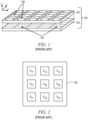
- FIG. 1 is an illustrative drawing showing details of a known imager sensor 180 in accordance with some embodiments.
- the image sensor 180 includes an optic array of lens stacks 182 and an array of sensors 184.
- Each sensor in the array includes a two dimensional arrangement of pixels having at least two pixels in each dimension.
- Each sensor includes a lens stack 186 that creates a separate optical channel that resolves an image onto a corresponding arrangement of pixels disposed in a focal 188 plane of the lens stack.
- the pixels act as light sensors and each focal plane 188 with its multiple pixels acts as an image sensor.
- Each sensor with its focal plane 182 occupies a region of the sensor array different from regions of the sensor array occupied by other sensors and focal planes.
- FIG 2 is an illustrative drawing showing a simplified plan view of the known imager sensor array 180 of Figure 1 that includes sensors S 11 through S 33 .
- the imager sensor array 180 is fabricated on a semiconductor chip to include a plurality of sensors S 11 through S 33 Each of the sensors S 11 through S 33 includes a plurality of pixels (e.g., 0.32 Mega pixels) and is coupled to peripheral circuitry (not shown) that includes independent read-out control and pixel digitization.
- the sensors S 11 through S 33 are arranged into a grid format as illustrated in Figure 2 .
- the sensors are arranged in a non-grid format.
- the imagers may be arranged in a circular pattern, zigzagged pattern or scattered pattern or an irregular pattern including sub-pixel offsets.
- Each sensor pixel includes a microlens pixel stack.
- Figure 3 is an illustrative drawing of a known microlens pixel stack of the sensors of Figures 1-2 .
- the pixel stack 800 includes a microlens 802, which sits atop an oxide layer 804, which is typically beneath the oxide layer 804 there may be a color filter 806, which is disposed above a nitride layer 808, which is disposed above a second oxide layer 810, which and sits atop a silicon 812 that layer includes the active area 814 of the sensor (typically a photodiode).
- the primary role of a microlens 802 is to gather the light incident on its surface and to focus that light onto the small active area 814.
- the pixel aperture 816 is determined by the spread of the microlens, which collects the light and focuses it on the active area 814.
- US 2013/0038689 discloses an image capture unit which includes a prism assembly and sensor assembly.
- the prism assembly includes a beam splitter, while the sensor assembly includes coplanar image capture sensors.
- Each of the coplanar image capture sensors has a common front end optical structure, e.g., the optical structure distal to the image capture unit is the same for each of the sensors.
- a controller enhances images acquired by the coplanar image capture sensors.
- the enhanced images may include (a) visible images with enhanced feature definition, in which a particular feature in the scene is emphasized to the operator of minimally invasive surgical system; (b) images having increased image apparent resolution; (c) images having increased dynamic range; (d) images displayed in a way based on a pixel color component vector having three or more color components; and (e) images having extended depth of field.
- US 2013/0035583 discloses a synthesis image in which medical images captured using different medical image capturing apparatuses are registered is generated by mapping the medical images to each other.
- the synthesis image may be used for image guidance while a diagnosis or a robotic surgery of a patient is being performed.
- JP 2006 305332 A discloses an image processor which is equipped with an image pickup means for picking up two-dimensional images and an image forming means forming a three-dimensional image from a plurality of two-dimensional images. Since the image forming means is equipped with units U each comprising a plurality of lenses disposed in a matrix, the image forming means can acquire two-dimensional images corresponding to the number of the units U.
- a calibration assembly includes: a target surface extends in three dimensions with calibration markers and a body with an interface that engages an endoscope so the markers are within the field of view.
- a first calibration marker extends along a first plane of the target surface and a second marker extends along a second plane of the target surface. The planes are different and asymmetric relative to the field of view as seen through the endoscope.
- WO 2013/156893 A1 discloses systems and methods for guided endoscope navigation which include a registration module configured to, using a processor, register a first set of images with a second set of images of an endoscope.
- a selection module is configured to receive selected areas of interest on the first set of images and transform the selected areas of interest to an endoscope coordinate frame.
- a guidance module is configured to overlay guidance tools onto the second set of images to permit a user of the endoscope to navigate to the selected areas of interest.
- an image sensor array that includes an imager sensor array is associated with an endoscope.
- the image sensor array includes multiple sensors and each sensor includes an array of pixels.
- a portion of the endoscope is inserted into a human body cavity and a target object in a field of view of the image sensor array is illuminated using a light source.
- a physical location and/or dimensions of the target object is determined based upon projected images of the object onto individual sensors of the array.
- Figure 4 is an illustrative drawing showing a perspective view of a surgical scene through a viewer 312 in accordance with some embodiments.
- a viewing system having two imaging elements 206R, 206L can provide a good 3D viewing perspective.
- Numerical values representing physical dimension and/or location information for physical structures in the surgical scene are shown overlaid onto the surgical scene image. For example, a numerical distance value "d_Instr Trgt" is shown displayed within the scene between instrument 400 and target 410.
- Teleoperation refers to operation of a machine at a distance.
- a surgeon may use a camera mounted on an endoscope to view a surgical site within a patient's body. Three-dimensional images have been generated to provide high resolution view during surgery.
- a camera system which is mounted on an endoscope and which includes an imager sensor array, provides quantitative three-dimensional information plus color and illumination data that can be used to generate three-dimensional images in accordance with some embodiments.
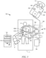
- FIG. 5 is an illustrative block diagram of a teleoperation surgery system 100 to perform minimally invasive surgical procedures using one or more mechanical arms 158 in accordance with some embodiments.
- system 100 includes telerobotic and autonomously operating features. These mechanical arms often support an instrument.
- a mechanical surgical arm e.g., the center mechanical surgical arm 158C
- the mechanical surgical arm 158C may include a sterile adapter, or a clamp, clip, screw, slot/groove or other fastener mechanism to mechanically secure the image capture device 101C to the mechanical arm.
- the image capture device 101C may include physical contours and/or structures complementary to those of the mechanical surgical arm 158C so as to securely interfit with them.
- a user or operator O performs a minimally invasive surgical procedure on patient P by manipulating control input devices 160 at a master control console 150.
- the operator can view video frames of images of a surgical site inside a patient's body through a stereo display device 164, which includes the viewer 312 described above with reference to Figure 4 .
- a computer 151 of the console 150 directs movement of teleoperationally controlled endoscopic surgical instruments 101A-101C via control lines 159, effecting movement of the instruments using a patient-side system 152 (also referred to as a patient-side cart).
- the patient-side system 152 includes one or more mechanical arms 158.
- the patient-side system 152 includes at least three mechanical surgical arms 158A-158C (generally referred to as mechanical surgical arms 158) supported by corresponding positioning set-up arms 156.
- the central mechanical surgical arm 158C may support an endoscopic camera 101C suitable for capture of Q3D information for images within a field of view of the camera.
- the mechanical surgical arms 158A and 158B to the left and right of center may support instruments 101A and 101B, respectively, which may manipulate tissue.
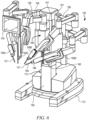
- FIG. 6 is an illustrative perspective view of the patient-side system 152 in accordance with some embodiments.
- the patient-side system 152 comprises a cart column 170 supported by a base 172.
- One or more mechanical surgical arms 158 are respectively attached to one or more set-up arms 156 that are a part of the positioning portion of the patient-side system 152.
- the cart column 170 includes a protective cover 180 that protects components of a counterbalance subsystem and a braking subsystem from contaminants.
- each mechanical surgical arm 158 is used to control instruments 101A-101C. Moreover, each mechanical surgical arm 158 is coupled to a set-up arm 156 that is in turn coupled to a carriage housing 190 in one embodiment of the invention. The one or more mechanical surgical arms 158 are each supported by their respective set-up arm 156, as is illustrated in Figure 6 .
- the mechanical surgical arms 158A-158D may each include one or more displacement transducers, orientational sensors, and/or positional sensors 185 to generate raw uncorrected kinematics data, kinematics datum, and/or kinematics information to assist in acquisition and tracking of instruments.
- the instruments may also include a displacement transducer, a positional sensor, and/or orientation sensor 186 in some embodiments of the invention.
- one or more instruments may include a marker 189 to assist in acquisition and tracking of the instruments.
- FIG. 7A is an illustrative drawing of a first image capture system 101C in accordance with some embodiments.
- the image capture system 101C includes an endoscope that includes elongated portion 202, which includes a first end portion 204 and a second end portion 206 and a tip portion 208 of the first end portion 204.
- the first end portion 202 is dimensioned to be inserted into a human body cavity.
- An imager sensor array 210 which includes multiple image sensors (not shown), is to the tip portion 208 of the first end portion 204.
- the elongated portion 202 has a length sufficient to position the tip portion 208 close enough to a target object within the body cavity that the object can be imaged by the imager sensor 210.
- the second end portion 206 may include physical contours and/or structures (not shown), as generally described above, so as to securely interfit with a mechanical arm (not shown).
- the elongated portion 202 also one or more electronic signal paths 212 to electronically communicate information with the imager sensor array 210.
- a light source 214 is disposed to illuminate the object to be imaged.
- the light source 214 can be unstructured light, white light, color filtered light or light at some selected wavelength, for example.
- FIG. 7B is an illustrative drawing of a second image capture system 101C', in accordance with some embodiments. Aspects of the second image capture system 101C' that are essentially the same as those of the first image capture system 101C are indicated by identical reference numerals and are not described again.
- An input to a light pipe input such as a rod lens, is disposed at the tip portion 208 of the first end portion 204.
- a light pipe body extends within the elongate portion 202 so as to transmit an image received as the light pipe input to the imager sensor array 210, which is physically displaced from the tip portion 208.
- the imager sensor is displaced far enough from the tip portion 208 that the sensor array 210 is located outside the body cavity during observation of objects within the cavity.
- FIG 8 is illustrative block diagram showing control blocks associated with the first image capture system 101C of Figure 7A and showing the system 101C in operation, in accordance with some embodiments.
- Images captured by the imager sensor array 210 are sent over a data bus 212 to a video processor 104, which communicates via bus 105 with a controller 106.
- the video processor 104 may comprise a camera control unit (CCU) and a video signal detector (VSD) board.
- the CCU programs or controls various settings of the imaging sensor 210, such as brightness, color scheme, white balance, etc.
- the VSD processes the video signal received from the imaging sensor.
- a processor system that includes one or more than one processor is configured to perform processor functions.
- the processor system includes multiple processors configured to operate together to perform the processor functions described herein.
- reference herein to at least one processor configured to perform one or more functions includes a processor system in which the functions may be performed by one processor alone or by multiple processors working together.
- the CCU and VSD could be integrated into one functional block.
- the controller 106 which includes a processor and a storage device (not shown) computes the physical quantitative 3D coordinates of the points in a scene adjacent the tip 208 of the elongated portion and drives both the video processor 104 and a 3D display driver 109 to compose 3D scenes, which then can be displayed on a 3D display 110.
- Data buses 107 and 108 exchange information and control signals among the video processor 104, the controller 106 and the display driver 109.
- these elements can be integrated with the image sensor array 210 inside the body of endoscope 202. Alternatively, they can be distributed internally and/or externally to the endoscope.
- the endoscope 202 is shown positioned, via a cannula 140, to penetrate body tissue 130 in order to provide visualize access to a surgical scene that includes a target 120.
- the target 120 can be an anatomic target, another surgical instrument or any other aspect of the surgical scene inside a patient's body.
- FIG. 4 is an illustrative drawing showing a perspective view of a viewer 312 of the master control console 150 of Figure 5 in accordance with some embodiments.
- the viewer 312 includes stereo images for each eye including a left image 400L and a right image 400R of the surgical site including any instruments 400 and a target 410 respectively in a left viewfinder 401L and a right viewfinder 401R.
- the images 400L and 400R in the viewfinders may be provided by a left display device 402L and a right display device 402R, respectively.
- the display devices 402L,402R may optionally be pairs of cathode ray tube (CRT) monitors, liquid crystal displays (LCDs), or other type of image display devices (e.g., plasma, digital light projection, etc.).
- the images are provided in color by a pair of color display devices 402L, 402R; such as color CRTs or color LCDs.
- stereoscopic display devices 402L and 402R may be used with a Q3D system.
- the Q3D imaging system can be connected to 3D monitors, 3D TVs, or to autostereoscopic displays, such as a display that does not require use of 3D effect eye glasses.
- a viewing system having two imaging elements 206R, 206L can provide a good 3D viewing perspective.
- the Q3D imaging system supplements this viewing perspective with physical dimension information for physical structures in the surgical scene.
- the stereo viewer 312 used in conjunction with a Q3D endoscopy system can display Q3D information overlayed onto the stereo image of the surgical scene. For example, as shown in Figure 4 , the numerical Q3D distance value "d_Instr_Trgt" between instrument 400 and target 410 can be displayed within stereo viewer 312.
- FIG 9 is an illustrative flow diagram representing a process to determine a quantitative three dimensional location of a physical target in accordance with some embodiments.
- the process is described with reference to the Q3D system 101C of the embodiment of Figure 8
- Module 401 configures the controller 106 to acquire video data from imaging sensors S ij .
- the video data may include color and light intensity data.
- Each pixel of each sensor may provide one or more signals indicative of the color and intensity of an image projected onto it.
- Module 402 configures the controller to systematically select targets from a selected region of interest in a physical world view.
- Module 403 configures the controller to commence the computation of the target 3D coordinates (x, y, z) with an initial (x 0 , y 0 , z 0 ) set. The algorithm then checks the coordinates for consistency, by using image diversity data from all sensors Sij that see the target. The coordinate computation is refined at step 404 until an acceptable accuracy is reached.
- Decision module 404 configures the controller to determine whether the currently computed physical location is sufficiently accurate. In response to a determination that the currently computed location is not accurate enough, control flows back to module 403 to try a different possible physical location.
- module 405 configures the controller to determine whether the entire region of interest has been scanned. In response to a determination that the entire region of interest has not been scanned, control flows back to module 402 and a different target is selected. In response to a determination that the entire region of interest has been scanned, control flows module 406 configures the controller to assemble a three-dimensional model of the imaging module of interest. Assembly of a 3D image of a target based upon from three-dimensional information indicating the physical position of structures of the target is known to persons of ordinary skill in the art and need not be described herein. Module 407 configures the controller to store the 3D model developed using the physical position information determined for multiple targets for further review and manipulation.
- the 3D model could be used at a later time for surgical applications such as sizing an implant for the particular dimensions of a patient's organ.
- Module 408 configures the controller to use the physical position information determined for multiple targets to display a quantitative 3D view.
- An example of a Q3D view is the distance value "d_Instr_Trgt" shown in Figure 4 .
- FIG 10 is an illustrative flow diagram showing certain details of a process generally corresponding to module 402 of Figure 9 in accordance with some embodiments.
- Module 402.1 configures the controller to capture images of a physical world scene from all sensors in the sensor array 210.
- Module 402.2 configures the controller to specify a region of interest from within the captured scene.
- Module 402.3 configures the controller to search for a best match as between scene images within the region of interest so as to identify pixel locations in different sensors that are illuminated by projections of the same target. As explained later, the best matching may be achieved, without limitation, by shifting the individual images from sensors S ij until maximizing two-dimensional cross-correlation function between the shifted image and a reference image.
- the reference image may be the scene image received from sensor S 11 .
- Module 402.4 configures the controller to identify candidate pixels illuminated by projections from the same target.
- Module 402.5 configures the controller to compute two or more pixel coordinates (N x , N y ) coordinates for the selected target to determine whether the candidate pixels are illuminated by a projection from the same target.
- Decision module 402.6 determines whether the computed 2D pixel coordinate values indicate that the candidate pixels are illuminated by a projection from the same target.
- the image diversity caused by viewing the same scene with multiple sensors S ij plays a role in correctly identifying (N x , N y ) associated with a specific target in the various individual images S ij .
- ⁇ 12 and ⁇ 13 should be equal if pixel coordinates (Nx 11 , Ny 11 ), (Nx 12 , Ny 12 ), (Nx 13 , Ny 13 ) come from projections of the same target.
- y ⁇ 12 Ny 11 Ny 11 ⁇ Ny 12
- y ⁇ 13 2 ⁇ Ny 11 Ny 11 ⁇ Ny 13
- the norm of the difference between ⁇ i,j and ⁇ ij+1 should be less than an acceptable tolerance ⁇ in order for module 402 to complete its iterations.
- a similar restriction should be met for the corresponding estimates for the x axis, x i,j and x i , j +1 .
- each pixel directly captures color and intensity information from a world scene. Moreover, in accordance with the above process, each pixel is associated with the (x, y, z) coordinates of the physical object in the world view that is projected onto the pixel. Thus, color information, illumination intensity information and physical location information, i.e. the location of the physical object that projected the color and illumination, can be associated with a pixel in a non-transitory computer readable storage device.
- Table 1 illustrates this association. Table 1 Pixel Identifier Color Value Intensity Value Location (x, y, z)
- FIG 11 is an illustrative drawing of an example sensor imager array 210 that includes multiple sensors S 11 -S 33 that is disposed to have a field of view that encompasses an illustrative three dimensional physical world scene that includes three illustrative objects in accordance with some embodiments.
- Each sensor in the array includes a two dimensional arrangement of pixels having at least two pixels in each dimension.
- Each sensor includes a lens stack that creates a separate optical channel that resolves an image onto a corresponding arrangement of pixels disposed in a focal plane of the lens stack.
- Each pixels act as a light sensor and each focal plane with its multiple pixels acts as an image sensor.
- Each sensor S 11 -S 33 with its focal plane occupies a region of the sensor array different from regions of the sensor array occupied by other sensors and focal planes.
- Suitable known image sensor arrays are disclosed in U.S. Patent No. 8,514,491 and in U.S. Patent Application Pub. No. 20013/0070060 , which are described above.
- the sensors are characterized by a N x and N y , their total number of pixels in the x and y directions, and by field of view angles, ⁇ x and ⁇ y .
- the sensor characteristics for the x and y axes are expected to be the same.
- the sensors have asymmetric x and y axes characteristics.
- all sensors will have the same total number of pixels and the same field of view angle.
- the sensors are distributed across the array 210 in a well-controlled manner.
- the sensors may be at ⁇ distance apart on the two-dimensional grid shown.
- the sensor placement pitch ⁇ may be symmetric or asymmetric across such grid.
- the sensors are arranged in a rectangular grid in which sensors S 11 -S 13 occupy a top row, sensors S 21 -S 23 occupy a middle row, and sensors S 31 -S 33 occupy a bottom row.
- Each sensor includes N rows of pixels and N columns of pixels.
- Light rays, indicated by dashed lines, produced by a light source are reflected from each of a triangle shaped first object, a spherical shaped second object and a rectangular shaped third object, to each sensor of the imager array. For illustration purposes, only rays to sensors S 11 , S 12 and S 13 in the top row are shown.
- the light source may be non-structured white light or ambient light, for example.
- the light source may provide light at a selected wavelength such as infrared, or may be filtered or split to provide a selected color or range of colors, for example. It will be appreciated that light rays are similarly reflected from each of the objects to sensors S 21 -S 33 . However, in order to simplify the explanation, these other light rays are not shown.
- sensors of the array separately capture images from a world view, and in accordance with module 402.1.
- Figure 12 is an illustrative drawing representing projections of the three objects of Figure 11 onto the sensors S ij (only S 11 , S 12 and S 13 shown) in accordance with some embodiments.
- the reflected light rays incident upon that sensors project images of the objects that are in the field of view. More specifically, the rays of light reflected from the objects in the field of view that are incident upon multiple different image sensors of the imager array produce multiple perspective projections of the objects from three-dimensions to two dimensions, i.e. a different projection in each sensor that receives the reflected rays.
- the relative location of projections of the objects is shifted from left to right when progressing from S 11 to S 12 to S 13 .
- Image sensor pixels that are illuminated by incident light rays produce electrical signals in response to the incident light. Accordingly, for each image sensor, a pattern of electrical signals is produced by its pixels in response to the reflected rays that indicates the shape and location of the image projection within that image sensor.
- a region of interest is selected from the world scene.
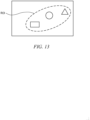
- Figure 13 is an illustrative drawing indicating selection of a region of interest from within the scene.
- the triangle shaped first object, spherical shaped second object and rectangular shaped third object all are in the selected region of interest.
- This step can be achieved by accepting input from an operator, or it can be automatically performed using a computer configured by software in a prescribed manner, or by combination of operator inputs and automatic software-controlled selection.
- the world scene may show an internal cavity of the human anatomy and the objects may be internal body organs or surgical instruments or portions thereof.
- a surgeon may receive real time visual imagery from within the internal cavity and may have within her field of view tissue regions of the human anatomy and a portion of the surgical instruments projecting within the body cavity.
- the surgeon may specify those objects within the field of view for which location information is to be determined through well-known techniques such as a video marker such as telestration, for example.
- a video marker such as telestration
- an automated process such as an edge detection algorithm can be used to specify a region of interest (ROI).
- ROI region of interest
- a best match is determined as between scene images within the region of interest so as to identify pixel locations in different sensors that are illuminated by projections of the same target.
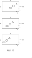
- Figure 14 is an illustrative drawing showing additional detail as to relative geometric offset of the projected images in sensors S 11 , S 12 and S 13 in accordance with some embodiments.
- an image from sensor S 13 is considered to be reference image
- the projections of the objects in the selected ROI are offset to the right by an amount ⁇ 23 pixels in sensor S 12 relative to their location in sensor S 13 .
- the projections of the objects in the selected ROI are offset to the right by an amount ⁇ 13 pixels in sensor S 11 relative to their location in sensor S 13 .
- Figure 15 is an illustrative drawing showing the projected images in sensors S 11 and S 12 within the ROI shifted to the right to align with the projected images in sensor S 13 within the ROI in accordance with some embodiments.
- sensor S 13 is designated to act as a reference sensor. It will be appreciated that other sensors can be chosen for use in determining alignment and geometric dimensions. Projections of the objects within the selected ROI are identified in the designated sensor, e.g., sensor S 13 , and projections in the other sensors, e.g., in sensors S 11 and S 12 , are shifted until they align with the projection in the designated sensor. In this manner, the corresponding projections of objects within the selected ROI can be identified within the other sensors, together with their offsets relative to the location of the projections in the designated sensor.
- the projections of the three example objects are shifted to the right by an amount ⁇ 23 pixels in sensor S 12
- the projections of the three example objects are shifted to the right by an amount ⁇ 13 pixels in sensor S 13 .
- the projections are offset in the y direction only and not in the x direction, although the same principles apply for x direction projection offsets as between sensors.
- this example shows a linear offsets, a person of ordinary skill in the art can apply other transformations such as rotation, for example, to align projections that have relative offsets in different sensors.
- two-dimensional (2D) cross-correlation techniques or principal component analysis (PCA) can be used to align the projections within the ROI in S 13 with the projections within the ROI in S 12 and to align the projections within the ROI in S 13 with the projections within the ROI in S 11 .
- the intent is to best match or align the images from sensors S ij with respect to the image from the sensor designated as reference. More specifically, the projected images within the ROI in S 12 are shifted and cross-correlated with the projected images within the ROI in S 13 until a highest correlation coefficient is achieved. Likewise, the projected images within the ROI in S 11 are shifted and cross-correlated with the projected images within the ROI in S 13 until a highest correlation coefficient is achieved.
- alignment of the projections of the ROI is used to identify the locations of the projections of the ROI in sensors S 11 and S 12 by determining the offset between the projection of the ROI in S 13 and the projection of the ROI in S 12 and by determining the offset between the projection of the ROI in S 13 and the projection of the ROI in S 11 .
- candidate pixels are identified within different sensors, which according to the best match process, are illuminated by projections from the same target.
- the physical (x, y, z) projections of individual target points within the ROI can be determined relative to the imager array.
- one or more pixels within each of multiple sensors is identified that is illuminated by a projection from the target point.
- a physical (x, y, z) target point location is determined based at least in part upon the geometric relationships among pixels disposed in different sensors that are determined to be illuminated by projections from the target point.
- a sequence of target points can be chosen automatically by systematically traversing the ROI (e.g., right to left with a certain step size and up to down with a step size), and a physical (x, y, z) target point location can be determined for each selected target point. Since S 11 and S 12 are best matched to S 13 , the traversing is performed inside the shifted regions of interest. Selecting a target involves identifying a pixel in each of sensors S 11 , S 12 and S 13 that is illuminated by a projection of the target. Thus, candidate pixels in each of S 11 , S 12 and S 13 are identified as being the ones illuminated by a projection of the selected target point.
- a pixel is selected in each of the sensors S 11 , S 12 and S 13 that is illuminated by a projection of the target point T.
- the (x, y, z) physical location of the target T is unknown at the moment of its selection.
- inaccuracy of the above-described alignment process can result in inaccuracy in the determination of which pixels in each sensor are illuminated by the projection of a selected target T.
- a further determination is made as to the accuracy of the determination as to the pixels in each of S 11 , S 12 and S 13 that are illuminated by the projection of a currently selected target T.
- Figure 16 is an illustrative drawing showing projections of the selected triangle shaped target point onto sensors S 11 , S 12 and S 13 in accordance with some embodiments. From these projections, the 2D pixel coordinates for target T are determined, [(Nx 11 , Ny 11 ), (Nx 12 , Ny 12 ), (Nx 13 , Ny 13 )]. For simplification, Figure 16 shows only the y-axis pixel coordinates. Using these 2D pixel coordinates, expressions (402.5 - 1) and (402.5 - 2) are applied and ⁇ 12 and ⁇ 13 computed as part of module 402.5.
- module 402.6 Part of module 402.6, the norm
- FIG. 17 there is shown a portion of an imager array that includes sensors S 11 , S 12 and S 13 and the selected triangle shaped first object target point T disposed at location (x, y, z) in physical space.
- Sensors within an imager array have a known spacing between them, ⁇ ij .
- the physical position spacing between S 11 and S 12 is ⁇ 12
- the physical position spacing between S 12 and S 13 is ⁇ 23 .
- these spacing between all sensors S ij is identical, equal to ⁇ , a constructional specification.
- Sensors S ij also have a known field of view angle ⁇ .
- each sensor is constructed as a 2D imaging element with pixels arranged in a rectangular pattern of rows and columns.
- pixels can be arranged in a circular pattern, zigzagged pattern or scattered pattern or an irregular pattern including sub-pixel offsets, for example.
- the angle and the pixel characteristics of these elements may be identical or, alternatively, may be different from sensor to sensor. However, these characteristics are assumed to be known. In order to simplify the explanation, it is assumed that the sensors are identical, although they may, however, be different.
- the N-pixel width of the sensor expands out to a y-dimension field of view of S 11 indicated by FOV 1 .
- the y-dimension field of view of sensor S 12 is indicated by FOV 2 .
- the y-dimension field of view of sensor S 13 is indicated by length FOV 3 .
- the lengths FOV 1 , FOV 2 and FOV 3 overlap each other, signifying that sensors S 11 , S 12 and S 13 achieve a 3-way sampling diversity of target T physically located at some (unknown) distance z.
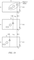
- FIG. 18 there is shown an illustrative elevation view of the projection of the currently selected target point T onto the image sensors S 11 , S 12 and S 13 .
- the sensors include geometrically rectangular pixel arrays of size NxN pixels.
- the x coordinates of the target T projections are all equal.
- a person of skill in the art would know how to modify the process presented below so that to compute the x, y and z physical coordinates of target T if any of the above assumptions would change.
- An image of the target T is projected to a physical point within sensor S 11 at geometric coordinates (n x1 , n y1 ), in the plane of the image sensor S 11 . More specifically, the projection of target point T onto sensor S 11 is located n y1 pixels along the y axis, and nx1 pixel along the x axis, taken from the origin. An image of the target T is projected to a physical point within sensor S 12 at geometric coordinates (n x2 , n y2 ), in the plane of the image sensor S 12 . An image of the target T is projected to a physical point within sensor S 13 at geometric coordinates (n x3 , n y3 ), in the plane of the image sensor S 13 .
- pixel locations (n xi , n yi ) within each sensor are determined relative to origin (0, 0,) reference coordinates provided for the sensor.
- a global system of coordinates (x, y, z) is defined and used to reference the target.
- the origin of such system of coordinates may be placed, without limitations, at the geometrical center of sensor S 11 .
- the y pixel distance of the projection of the target is different in each sensor.
- the projection of a currently selected target T is disposed n y1 pixels to the left of the origin in S 11 .
- the projection of the selected target T is disposed n y2 pixels to the left of the origin in S 12 .
- the projection of the selected target T is disposed n y3 pixels to the left of the origin in S 13 .
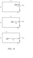
- FIG. 19 there is shown the disposition of the currently selected target T relative to sensors S 11 , S 12 and S 13 as described above with reference to Figure 17 and also showing y-direction pixel offsets for the candidate pixel in each of the sensors.
- the drawings of Figure 19 present physical structures and an analytical framework for determining the (x, y, z) physical coordinates of the selected target point T.
- FOV i This length, FOV i , corresponds to the maximum pixel width of the sensor, which is N pixels, in some embodiments. Given that the working assumption was that the sensor has a field of view that is symmetric in the x and y directions, the length would also be FOV i vertically, along the x axis.
- the candidate pixel selections are made based at least in part upon a correlation process that can have a level of uncertainty than can result in inaccuracy in determination of the physical location of the selected target.
- a further check of the accuracy of the target projection candidate selections is made as follows.
- two or more two-dimensional (N x , N y ) coordinate values are computed for the selected target to determine whether the candidate pixels actually are illuminated by a projection from the same target.
- determination of the physical x coordinate of the selected target T can be determined based upon expressions (3) or (6).
- a determination of the physical y coordinate of the selected target T can be determined based upon expressions (2) or (5).
- a determination of the physical z coordinate of the selected target T can be determined based upon equations (1) or (4).
- the y coordinate for the target T can be determined using both formulations (2) and (5). If the resulting y coordinate values computed using the two formulations differ by more than some acceptable tolerance value, ⁇ y , then a determination can be made that the matching process failed to resolve the offset between projections in the different sensors with sufficient accuracy, and as result that the candidate pixels do not correspond in that they do not receive projections from the same target T.
- an initial estimate for the z coordinate, z 0 is used to initiate the computation process.
- This initial value is defined automatically, according to the medical application.
- the medical application defines the intended world view to be visualized.
- the initial value z 0 starts at the edge of the field of view closest to the endoscope.
- z 0 can be 1 - 5 mm off the distal end 208 of the Q3D endoscope 202, for example.
- Such initial estimate generally is sufficient for this application as it is unlikely to have any tissues or surgical instruments reside in such close proximity to the Q3D endoscope.
- value z 0 is plugged into formulations (3) and (6). Given that the x coordinate of the target is unique, if z 0 were the true and correct z coordinate of the target then formulations (3) and (6) would yield identical values, or approximately equal, within an acceptable level of tolerance, ⁇ x . x 3 ⁇ x 6 ⁇ ⁇ x
- z 1 z 0 + ⁇
- ⁇ is the size of the iteration step.
- z k z k-1 + ⁇ .
- the iterative process stops when condition (7) is met.
- a smaller ⁇ yields increased accuracy in determining the correct target coordinates, but would also require more computational time to complete the process, hence an increased latency.
- An increased latency may results in delays between surgical instrument movement and its visualization by the operating surgeon. In other words, the surgeon may perceive the system as lagging behind his commands. For a surgical viewing space of 20 - 30 cm of depth, a ⁇ of 0.1 - 0.3 mm may be sufficient.
- a person skilled in the art would know to balance the size of ⁇ against the computational required to complete the iterative process.
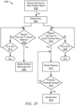
- Figure 20 is an illustrative flow diagram representing a first process 2000 to use Q3D information during a surgical procedure in accordance with some embodiments.
- Computer program code configures the computer 151 to perform the process 2000.
- Module 2002 configures the computer to receive user input to select at least two objects within a surgeon's field of view when looking in to the viewer 312.
- Module 2004 configures the computer to display a menu on a computer console in response to receipt of a user selection.
- Decision module 2006 configures the computer to determine whether user input to the menu is received to display a distance.
- module 2008 configures the computer to display a numerical distance within the video image in the surgeon's field of view.
- Decision module 2010 configures the computer to wait for a prescribed time interval for receipt of user input to select distance display and to end operation of decision module 2006 in response to no receipt of user input within a ⁇ time out' interval.
- Decision module 2012 configures the computer to determine whether user input to the menu is received to enter a proximity alarm limit.
- module 2014 configures the computer to use Q3D information to monitor proximity between two or more objects within the surgeon's field of view.
- Decision module 2016 determines whether the proximity threshold has been crossed.
- module 2018 configures the computer to activate an alarm.
- the alarm may include a sound, a visual queue such as a blinking light or locking of instrument movement to avoid collision.
- control flows back to monitoring module 2014.
- Decision module 2020 configures the computer to wait for the prescribed time interval for receipt of user input to enter the proximity threshold and to end operation of decision module 2012 in response to no receipt of user input within the 'time out' interval.
- Figures 21 is an illustrative drawing showing menu selections displayed on a display screen 2102 in accordance with the process of Figure 20 in accordance with some embodiments.
- the display screen 2102 includes a viewing monitor associated with the computer 151.
- the display screen 2102 may include a region of the imaging elements 206R, 206L of the viewer 312.
- module 2004 causes the display of a menu 2104 that includes a first menu item ⁇ Display Distance' 2106 and a second menu item ⁇ Set Proximity Alarm' 2108.
- module 2008 causes a display of Q3D distance between two or more objects.
- an ⁇ Enter Distance' UI input 2110 is displayed that includes a field in which a user can enter a proximity distance threshold value, e.g., "xxxx millimeters".
- a proximity distance threshold value e.g., "xxxx millimeters”.
- a default proximity threshold may be set in advance for all instruments, and a user may change the proximity threshold using the menu of Figure 21 , for example.
- a user can choose to elect the default threshold value rather than enter a threshold value.
- a user can select both to display the distance and set a proximity alert.
- Figures 22A-22B are illustrative drawings representing certain details of receiving user input in accordance with the process of Figure 20 in accordance with some embodiments.
- Figure 22A shows example first highlighting 2202L, 2202R of a target 410L, 410R, such as body tissue, which can be created using video marker tool, such as telestration, or using the surgeon console manipulating control input devices 160 of Figure 4 .
- Figure 22B shows example second highlighting 2206L, 2206R of an instrument tip 400L, 400R, which can be created using the video marker tool.
- a user creates the first highlighting 2202L, 2202R.
- the user creates second highlighting 2206L, 2206R of the instrument tip 400L, 400R using video marker tool. It will be understood that the order in which items are highlighted is unimportant.
- the user then actuates a selector (not shown) (e.g., press the ENTER key) to enter the selection.
- Module 2002 interprets the received user input as selection of the target image 410L, 410R and the instrument image 400L, 400R.
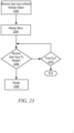
- Figure 23 is an illustrative flow diagram representing a second process 2300 to use Q3D information during a surgical procedure in accordance with some embodiments.
- Computer program code configures the computer 151 to perform the process 2300.
- Module 2302 configures the computer to receive user input to select an object within a surgeon's field of view when looking in to the viewer 312. For example, referring again to Figure 22A , user input is shown received to create the second highlighting 2206L, 2206R of the instrument tip 400L, 400R using the video marker tool.
- User input (not shown) is received to actuate a selector (not shown) (e.g., press the ENTER key) to enter the selection of the image of the instrument tip 400L, 400R.
- a selector not shown
- module 2304 configures the computer to display a menu on a computer console.
- Decision module 2306 configures the computer to determine whether user input to the menu is received to rotate an image of a selected object.
- module 2308 configures the computer to display rotate the image to show a different three-dimensional perspective of the object.
- Decision module 2310 configures the computer to wait for a prescribed time interval for receipt of user input to rotate an image and to end operation of decision module 2306 in response to no receipt of user input within a 'time out' interval.
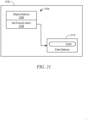
- Figure 24 is an illustrative drawing showing menu selections displayed on a display screen 2402 in accordance with the process of Figure 23 in accordance with some embodiments.
- the display screen 2402 includes a viewing monitor associated with the computer 151.
- the display screen 2402 may include a region of the imaging elements 206R, 206L of the viewer 312.
- module 2304 causes the display of a menu 2404 that includes a third menu item ⁇ Rotate Left' 2406 and a fourth menu item ⁇ Rotate Right' 2408.
- module 2308 uses the causes a rotation of the 3D model created and stored pursuant to module 407 of Figure 9 . It will be appreciated that the amount of rotation may be limited to a few degrees, less than 30 degrees for example, since the sensor imager array 210 has a limited overall field of view.
Description
- This application claims the benefit of priority to
U.S. provisional patent application no. 61/971,749, filed on March 28, 2014 - The invention relates in general to surgical endoscopy systems having associated image sensors, and more particularly, to determining three-dimensional coordinates of physical structures displayed in surgical images.
- Quantitative three-dimensional (Q3D) vision provides numerical information about the actual physical (x, y, z) 3D coordinates of target points in a real world scene. With quantitative 3D vision, a person not only can obtain a three-dimensional perception of a real world scene, but also can obtain numerical information about physical dimensions of objects in the scene and physical distances between objects in the scene. In the past, some Q3D systems have been proposed that use time-of-flight related information or phase information to determine 3D information about a scene. Other Q3D systems have used structured light to determine 3D information about a scene.
- The use of time-of-flight information is disclosed in
U.S. Patent No. 6,323,942 , entitled, "CMOS-compatible three-dimensional image sensor IC", which discloses a three-dimensional imaging system that includes a two-dimensional array of pixel light sensing detectors fabricated on a common IC using CMOS fabrication techniques. Each detector has an associated high speed counter that accumulates clock pulses in number directly proportional to time-of flight (TOF) for a system-emitted pulse to reflect from an object point and be detected by a pixel detector focused upon that point. The TOF data provides a direct digital measure of distance from the particular pixel to a point on the object reflecting the emitted light pulse. In a second embodiment, the counters and high speed clock circuits are eliminated, and instead each pixel detector is provided with a charge accumulator and an electronic shutter. The shutters are opened when a light pulse is emitted and closed thereafter such that each pixel detector accumulates charge as a function of return photon energy falling upon the associated pixel detector. The amount of accumulated charge provides a direct measure of round-trip TOF. - The use of time delay information is disclosed in
U.S. Patent No. 8,262,559 , entitled, "Apparatus and method for endoscopic 3D data collection", which discloses a modulated measuring beam, a light-transmitting mechanism for conducting the measuring beam onto an area to be observed, where the light-transmitting mechanism includes an illuminating lens, in addition to a light-imaging mechanism for imaging a signal beam from the area to be observed at least onto a phase-sensitive image sensor. Time delays, which may correspond to differences in depth in the mm range, result in phase information that makes possible the production of an image that depicts depth and distance information. - The use of structured light to determine physical coordinates of objects in a visual image is disclosed in
U.S. Pat. App. Pub. No. 2012/0190923 , entitled "Endoscope"; and in C. Schmalz et al., "An endoscopic 3D scanner based on structured light", Medical Image Analysis, 16 (2012) 1063-1072. A triangulation method is used to measure the topography of a surface. Structured light in the form of projection rays, which may have a range of different color spectra, are incident upon and are reflected from a surface. The reflected rays are observed by a camera that is calibrated to use the reflected color spectra information to determine 3D coordinates of the surface. More specifically, the use of structured light typically involves shining a light pattern on a 3D surface, and determining physical distances based upon a deformation pattern of the light due to contours of the physical object. - An imager array camera has been built that includes a plurality of pixel arrays that can be used to compute scene depth information for pixels in the array. High resolution (HR) images are generated from multiple low resolution (LR) images. A reference viewpoint is selected and an HR image is generated as seen by that viewpoint. A parallax processing technique utilizes the effects of aliasing to determine pixel correspondences for non-reference images with respect to the reference image pixels. Fusion and superresolution are utilized to produce the HR image from the multiple LR images. See,
U.S. Patent No. 8, 514, 491 , entitled "Capturing and Processing Images using Monolithic Camera Array with Heterogeneous Imager";U.S. Pat. App. Pub. No. 2013/0070060 , entitled, Systems and Methods for Determining Depth from multiple Views of a Scene that Include Aliasing using Hypothesized Fusion"; and K. Venkataraman et al., PiCam: An ultra-Thin high Performance Monolithic Camera Array. -
Figure 1 is an illustrative drawing showing details of a knownimager sensor 180 in accordance with some embodiments. Theimage sensor 180 includes an optic array of lens stacks 182 and an array ofsensors 184. Each sensor in the array includes a two dimensional arrangement of pixels having at least two pixels in each dimension. Each sensor includes alens stack 186 that creates a separate optical channel that resolves an image onto a corresponding arrangement of pixels disposed in a focal 188 plane of the lens stack. The pixels act as light sensors and eachfocal plane 188 with its multiple pixels acts as an image sensor. Each sensor with itsfocal plane 182 occupies a region of the sensor array different from regions of the sensor array occupied by other sensors and focal planes. -
Figure 2 is an illustrative drawing showing a simplified plan view of the knownimager sensor array 180 ofFigure 1 that includes sensors S11 through S33. Theimager sensor array 180 is fabricated on a semiconductor chip to include a plurality of sensors S11 through S33 Each of the sensors S11 through S33 includes a plurality of pixels (e.g., 0.32 Mega pixels) and is coupled to peripheral circuitry (not shown) that includes independent read-out control and pixel digitization. In some embodiments, the sensors S11 through S33 are arranged into a grid format as illustrated inFigure 2 . In other embodiments, the sensors are arranged in a non-grid format. For example, the imagers may be arranged in a circular pattern, zigzagged pattern or scattered pattern or an irregular pattern including sub-pixel offsets. - Each sensor pixel includes a microlens pixel stack.
Figure 3 is an illustrative drawing of a known microlens pixel stack of the sensors ofFigures 1-2 . Thepixel stack 800 includes amicrolens 802, which sits atop anoxide layer 804, which is typically beneath theoxide layer 804 there may be acolor filter 806, which is disposed above anitride layer 808, which is disposed above asecond oxide layer 810, which and sits atop asilicon 812 that layer includes theactive area 814 of the sensor (typically a photodiode). The primary role of amicrolens 802 is to gather the light incident on its surface and to focus that light onto the smallactive area 814. Thepixel aperture 816 is determined by the spread of the microlens, which collects the light and focuses it on theactive area 814. - Additional information concerning the above-described known imager sensor array architecture is provided in
U.S. Patent No. 8,514 ,491, issued, August 20, 2013 ; and inU.S. Patent Application Pub. No. 20013/0070060, published March 21, 2013 -
US 2013/0038689 discloses an image capture unit which includes a prism assembly and sensor assembly. The prism assembly includes a beam splitter, while the sensor assembly includes coplanar image capture sensors. Each of the coplanar image capture sensors has a common front end optical structure, e.g., the optical structure distal to the image capture unit is the same for each of the sensors. A controller enhances images acquired by the coplanar image capture sensors. The enhanced images may include (a) visible images with enhanced feature definition, in which a particular feature in the scene is emphasized to the operator of minimally invasive surgical system; (b) images having increased image apparent resolution; (c) images having increased dynamic range; (d) images displayed in a way based on a pixel color component vector having three or more color components; and (e) images having extended depth of field. -
US 2013/0035583 discloses a synthesis image in which medical images captured using different medical image capturing apparatuses are registered is generated by mapping the medical images to each other. The synthesis image may be used for image guidance while a diagnosis or a robotic surgery of a patient is being performed. -
JP 2006 305332 A -
US 2013/085329 A1 discloses calibration target devices, assemblies and methods for use with imaging systems, such as a stereoscopic endoscope. A calibration assembly includes: a target surface extends in three dimensions with calibration markers and a body with an interface that engages an endoscope so the markers are within the field of view. A first calibration marker extends along a first plane of the target surface and a second marker extends along a second plane of the target surface. The planes are different and asymmetric relative to the field of view as seen through the endoscope. -
WO 2013/156893 A1 discloses systems and methods for guided endoscope navigation which include a registration module configured to, using a processor, register a first set of images with a second set of images of an endoscope. A selection module is configured to receive selected areas of interest on the first set of images and transform the selected areas of interest to an endoscope coordinate frame. A guidance module is configured to overlay guidance tools onto the second set of images to permit a user of the endoscope to navigate to the selected areas of interest. - In the present invention, a quantitative three-dimensional (Q3D) imaging of surgical scenes is provided by the device and the method defined in the appended independent claims 1 and 5 respectively. Advantageous embodiments are defined in the appended dependent claims.
- Aspects of the present disclosure are best understood from the following detailed description when read with the accompanying figures. It is emphasized that, in accordance with the standard practice in the industry, various features are not drawn to scale. In fact, the dimensions of the various features may be arbitrarily increased or reduced for clarity of discussion. In addition, the present disclosure may repeat reference numerals and/or letters in the various examples. This repetition is for the purpose of simplicity and clarity and does not in itself dictate a relationship between the various embodiments and/or configurations discussed.
-
Figure 1 is an illustrative drawing showing details of a known imager sensor array. -
Figure 2 is an illustrative drawing showing a simplified plan view of a known imager sensor array that includes multiple sensors. -
Figure 3 is an illustrative drawing of a known microlens pixel stack. -
Figure 4 is an illustrative drawing showing a perspective view of a surgical scene through a viewer in accordance with some embodiments. -
Figure 5 is an illustrative block diagram of a teleoperation surgery system to perform minimally invasive surgical procedures using one or more mechanical arms in accordance with some embodiments. -
Figure 6 is an illustrative perspective view of a patient-side system of the system ofFigure 5 in accordance with some embodiments. -
Figure 7A is an illustrative drawing of a first image capture system in accordance with some embodiments. -
Figure 7B is an illustrative drawing of a second image capture system in accordance with some embodiments. -
Figure 8 is illustrative block diagram showing control blocks associated with the first image capture system ofFigure 7A and showing the system in operation, in accordance with some embodiments. -
Figure 9 is an illustrative flow diagram representing a process to determine a quantitative three dimensional location of a physical target in accordance with some embodiments. -
Figure 10 is an illustrative flow diagram showing certain details of a process generally corresponding to moduleFigure 9 to systematically select targets in accordance with some embodiments. -
Figure 11 is an illustrative drawing of an example sensor imager array that includes multiple sensors and that is disposed to have a field of view that encompasses an illustrative three dimensional physical world scene that includes three illustrative objects in accordance with some embodiments. -
Figure 12 is an illustrative drawing representing projections of the multiple physical objects ofFigure 11 onto multiple sensors in accordance with some embodiments. -
Figure 13 is an illustrative drawing indicating selection of a region of interest from within a real-world scene in accordance with some embodiments. -
Figure 14 is an illustrative drawing showing detail as to relative geometric offset of the projected images in sensors multiple sensors in accordance with some embodiments. -
Figure 15 is an illustrative drawing showing the projected images in certain example sensors within the region of interest (ROI) shifted to the right to align with the projected images in a designated reference sensor within the ROI in accordance with some embodiments. -
Figure 16 is an illustrative drawing showing projections of a selected target point onto multiple sensors in accordance with some embodiments. -
Figure 17 is an illustrative drawing showing a portion of an imager array that includes the multiple sensors ofFigure 16 and the selected target point T disposed at location in physical space in accordance with some embodiments. -
Figure 18 is an illustrative elevation view of the projection of the currently selected target point T onto the multiple image sensors ofFigure 16 in accordance with some embodiments. -
Figure 19 is an illustrative drawing showing the disposition of a currently selected target relative to the multiple sensors as described above with reference toFigure 17 and also showing y-direction pixel offsets for the candidate pixel in each of the sensors in accordance with some embodiments. -
Figure 20 is an illustrative flow diagram representing a first process to use Q3D information during a surgical procedure in accordance with some embodiments. -
Figures 21 is an illustrative drawing showing menu selections displayed on a display screen in accordance with the process ofFigure 20 in accordance with some embodiments. -
Figures 22A-22B are illustrative drawings representing certain details of receiving user input in accordance with the process ofFigure 20 in accordance with some embodiments. -
Figure 23 is an illustrative flow diagram representing a second process to use Q3D information during a surgical procedure in accordance with some embodiments. -
Figures 24 is an illustrative drawing showing menu selections displayed on a display screen in accordance with the process ofFigure 23 in accordance with some embodiments. - The following description is presented to enable any person skilled in the art to create and use a surgical endoscopy system having multiple image sensors, each sensor including a pixel array that is separate from pixel arrays of other sensors, to determine three-dimensional coordinates of physical structures within a field of view of the image sensors. Various modifications to the embodiments will be readily apparent to those skilled in the art, and the generic principles defined herein may be applied to other embodiments and applications without departing from the scope of the inventive subject matter. Moreover, in the following description, numerous details are set forth for the purpose of explanation. However, one of ordinary skill in the art will realize that the inventive subject matter might be practiced without the use of these specific details. In other instances, well-known machine components, processes and data structures are shown in block diagram form in order not to obscure the disclosure with unnecessary detail. Identical reference numerals may be used to represent different views of the same item in different drawings. Flow diagrams in drawings referenced below are used to represent processes. A computer system may be configured to perform some of these processes. Modules within flow diagrams representing computer implemented processes represent the configuration of a computer system according to computer program code to perform the acts described with reference to these modules. Thus, the inventive subject matter is not intended to be limited to the embodiments shown, but is to be accorded the widest scope consistent with the principles and features disclosed herein, as defined by the appended claims.
- In accordance with some embodiments, an image sensor array that includes an imager sensor array is associated with an endoscope. The image sensor array includes multiple sensors and each sensor includes an array of pixels. A portion of the endoscope is inserted into a human body cavity and a target object in a field of view of the image sensor array is illuminated using a light source. A physical location and/or dimensions of the target object is determined based upon projected images of the object onto individual sensors of the array.
-
Figure 4 is an illustrative drawing showing a perspective view of a surgical scene through aviewer 312 in accordance with some embodiments. A viewing system having two imaging elements 206R, 206L can provide a good 3D viewing perspective. Numerical values representing physical dimension and/or location information for physical structures in the surgical scene are shown overlaid onto the surgical scene image. For example, a numerical distance value "d_Instr Trgt" is shown displayed within the scene between instrument 400 and target 410. - Teleoperation refers to operation of a machine at a distance. In a minimally invasive teleoperation medical system, a surgeon may use a camera mounted on an endoscope to view a surgical site within a patient's body. Three-dimensional images have been generated to provide high resolution view during surgery. A camera system, which is mounted on an endoscope and which includes an imager sensor array, provides quantitative three-dimensional information plus color and illumination data that can be used to generate three-dimensional images in accordance with some embodiments.
-
Figure 5 is an illustrative block diagram of ateleoperation surgery system 100 to perform minimally invasive surgical procedures using one or more mechanical arms 158 in accordance with some embodiments. Aspects ofsystem 100 include telerobotic and autonomously operating features. These mechanical arms often support an instrument. For instance, a mechanical surgical arm (e.g., the center mechanicalsurgical arm 158C) may be used to support a stereo or three-dimensional surgicalimage capture device 101C such as an endoscope associated a Q3D image sensor array. The mechanicalsurgical arm 158C may include a sterile adapter, or a clamp, clip, screw, slot/groove or other fastener mechanism to mechanically secure theimage capture device 101C to the mechanical arm. Conversely, theimage capture device 101C may include physical contours and/or structures complementary to those of the mechanicalsurgical arm 158C so as to securely interfit with them. - A user or operator O (generally a surgeon) performs a minimally invasive surgical procedure on patient P by manipulating
control input devices 160 at amaster control console 150. The operator can view video frames of images of a surgical site inside a patient's body through astereo display device 164, which includes theviewer 312 described above with reference toFigure 4 . Acomputer 151 of theconsole 150 directs movement of teleoperationally controlled endoscopicsurgical instruments 101A-101C viacontrol lines 159, effecting movement of the instruments using a patient-side system 152 (also referred to as a patient-side cart). - The patient-
side system 152 includes one or more mechanical arms 158. Typically, the patient-side system 152 includes at least three mechanicalsurgical arms 158A-158C (generally referred to as mechanical surgical arms 158) supported by corresponding positioning set-uparms 156. The central mechanicalsurgical arm 158C may support anendoscopic camera 101C suitable for capture of Q3D information for images within a field of view of the camera. The mechanicalsurgical arms instruments -
Figure 6 is an illustrative perspective view of the patient-side system 152 in accordance with some embodiments. The patient-side system 152 comprises acart column 170 supported by abase 172. One or more mechanical surgical arms 158 are respectively attached to one or more set-uparms 156 that are a part of the positioning portion of the patient-side system 152. Situated approximately at a central location onbase 172, thecart column 170 includes aprotective cover 180 that protects components of a counterbalance subsystem and a braking subsystem from contaminants. - Excluding a
monitor arm 154, each mechanical surgical arm 158 is used to controlinstruments 101A-101C. Moreover, each mechanical surgical arm 158 is coupled to a set-uparm 156 that is in turn coupled to acarriage housing 190 in one embodiment of the invention. The one or more mechanical surgical arms 158 are each supported by their respective set-uparm 156, as is illustrated inFigure 6 . - The mechanical
surgical arms 158A-158D may each include one or more displacement transducers, orientational sensors, and/orpositional sensors 185 to generate raw uncorrected kinematics data, kinematics datum, and/or kinematics information to assist in acquisition and tracking of instruments. The instruments may also include a displacement transducer, a positional sensor, and/ororientation sensor 186 in some embodiments of the invention. Moreover, one or more instruments may include amarker 189 to assist in acquisition and tracking of the instruments. - Additional information about a teleoperation medical system is provided in
U.S. Patent Application Pub. No. 2012/0020547, published January 26, 2012 . -
Figure 7A is an illustrative drawing of a firstimage capture system 101C in accordance with some embodiments. Theimage capture system 101C includes an endoscope that includeselongated portion 202, which includes afirst end portion 204 and asecond end portion 206 and atip portion 208 of thefirst end portion 204. Thefirst end portion 202 is dimensioned to be inserted into a human body cavity. Animager sensor array 210, which includes multiple image sensors (not shown), is to thetip portion 208 of thefirst end portion 204. Theelongated portion 202 has a length sufficient to position thetip portion 208 close enough to a target object within the body cavity that the object can be imaged by theimager sensor 210. In accordance with some embodiments, thesecond end portion 206 may include physical contours and/or structures (not shown), as generally described above, so as to securely interfit with a mechanical arm (not shown). Theelongated portion 202 also one or moreelectronic signal paths 212 to electronically communicate information with theimager sensor array 210. Alight source 214 is disposed to illuminate the object to be imaged. In accordance with some embodiments, thelight source 214 can be unstructured light, white light, color filtered light or light at some selected wavelength, for example. -
Figure 7B is an illustrative drawing of a secondimage capture system 101C', in accordance with some embodiments. Aspects of the secondimage capture system 101C' that are essentially the same as those of the firstimage capture system 101C are indicated by identical reference numerals and are not described again. An input to a light pipe input, such as a rod lens, is disposed at thetip portion 208 of thefirst end portion 204. A light pipe body extends within theelongate portion 202 so as to transmit an image received as the light pipe input to theimager sensor array 210, which is physically displaced from thetip portion 208. In some embodiments, the imager sensor is displaced far enough from thetip portion 208 that thesensor array 210 is located outside the body cavity during observation of objects within the cavity. -
Figure 8 is illustrative block diagram showing control blocks associated with the firstimage capture system 101C ofFigure 7A and showing thesystem 101C in operation, in accordance with some embodiments. Images captured by theimager sensor array 210 are sent over adata bus 212 to avideo processor 104, which communicates via bus 105 with acontroller 106. Thevideo processor 104 may comprise a camera control unit (CCU) and a video signal detector (VSD) board. The CCU programs or controls various settings of theimaging sensor 210, such as brightness, color scheme, white balance, etc. The VSD processes the video signal received from the imaging sensor. - In accordance with some embodiments a processor system that includes one or more than one processor is configured to perform processor functions. In some embodiments the processor system includes multiple processors configured to operate together to perform the processor functions described herein. Thus, reference herein to at least one processor configured to perform one or more functions includes a processor system in which the functions may be performed by one processor alone or by multiple processors working together.
- Alternatively, the CCU and VSD could be integrated into one functional block. In one implementation, the
controller 106, which includes a processor and a storage device (not shown) computes the physical quantitative 3D coordinates of the points in a scene adjacent thetip 208 of the elongated portion and drives both thevideo processor 104 and a3D display driver 109 to compose 3D scenes, which then can be displayed on a3D display 110.Data buses video processor 104, thecontroller 106 and thedisplay driver 109. In some embodiments, these elements can be integrated with theimage sensor array 210 inside the body ofendoscope 202. Alternatively, they can be distributed internally and/or externally to the endoscope. Theendoscope 202 is shown positioned, via a cannula 140, to penetratebody tissue 130 in order to provide visualize access to a surgical scene that includes atarget 120. Thetarget 120 can be an anatomic target, another surgical instrument or any other aspect of the surgical scene inside a patient's body. - Example of Q3D Information Added to an Image of a Scene Referring once again to
Figure 4 is an illustrative drawing showing a perspective view of aviewer 312 of themaster control console 150 ofFigure 5 in accordance with some embodiments. In accordance with some embodiments, to provide a three-dimensional perspective, theviewer 312 includes stereo images for each eye including aleft image 400L and aright image 400R of the surgical site including any instruments 400 and a target 410 respectively in aleft viewfinder 401L and aright viewfinder 401R. Theimages left display device 402L and aright display device 402R, respectively. Thedisplay devices color display devices stereoscopic display devices - A viewing system having two imaging elements 206R, 206L can provide a good 3D viewing perspective. The Q3D imaging system supplements this viewing perspective with physical dimension information for physical structures in the surgical scene. The
stereo viewer 312 used in conjunction with a Q3D endoscopy system, can display Q3D information overlayed onto the stereo image of the surgical scene. For example, as shown inFigure 4 , the numerical Q3D distance value "d_Instr_Trgt" between instrument 400 and target 410 can be displayed withinstereo viewer 312. - An explanation of a video stereo viewing system that can be used to overlay physical location and dimension information onto a 3D perspective of a surgical scene is provided in
U.S. Patent Application Pub. No. 2012/0020547 , paragraphs [0043]-[0053] and corresponding drawings. - Processing Quantitative Three-Dimensional Physical Information
Figure 9 is an illustrative flow diagram representing a process to determine a quantitative three dimensional location of a physical target in accordance with some embodiments. The process is described with reference to theQ3D system 101C of the embodiment ofFigure 8 Module 401 configures thecontroller 106 to acquire video data from imaging sensors Sij. It will be appreciated that although theimage sensor array 210 "images" an entire field of view, different sensors and different pixels within different sensors may be illuminated by image projections from different object points within the field of view. The video data, for example, may include color and light intensity data. Each pixel of each sensor may provide one or more signals indicative of the color and intensity of an image projected onto it.Module 402 configures the controller to systematically select targets from a selected region of interest in a physical world view.Module 403 configures the controller to commence the computation of thetarget 3D coordinates (x, y, z) with an initial (x0, y0, z0) set. The algorithm then checks the coordinates for consistency, by using image diversity data from all sensors Sij that see the target. The coordinate computation is refined atstep 404 until an acceptable accuracy is reached.Decision module 404 configures the controller to determine whether the currently computed physical location is sufficiently accurate. In response to a determination that the currently computed location is not accurate enough, control flows back tomodule 403 to try a different possible physical location. In response to a determination that the currently computed location is sufficiently accurate,module 405 configures the controller to determine whether the entire region of interest has been scanned. In response to a determination that the entire region of interest has not been scanned, control flows back tomodule 402 and a different target is selected. In response to a determination that the entire region of interest has been scanned, control flowsmodule 406 configures the controller to assemble a three-dimensional model of the imaging module of interest. Assembly of a 3D image of a target based upon from three-dimensional information indicating the physical position of structures of the target is known to persons of ordinary skill in the art and need not be described herein.Module 407 configures the controller to store the 3D model developed using the physical position information determined for multiple targets for further review and manipulation. For example, the 3D model could be used at a later time for surgical applications such as sizing an implant for the particular dimensions of a patient's organ. In yet a different example, when a newsurgical instrument 101 is installed on therobotic system 152 it may be necessary to call back the 3D model and display it onmonitor 110 in order to reference the new instrument to the previous surgical scene.Module 408 configures the controller to use the physical position information determined for multiple targets to display a quantitative 3D view. An example of a Q3D view is the distance value "d_Instr_Trgt" shown inFigure 4 . -
Figure 10 is an illustrative flow diagram showing certain details of a process generally corresponding tomodule 402 ofFigure 9 in accordance with some embodiments. Module 402.1 configures the controller to capture images of a physical world scene from all sensors in thesensor array 210. Module 402.2 configures the controller to specify a region of interest from within the captured scene. Module 402.3 configures the controller to search for a best match as between scene images within the region of interest so as to identify pixel locations in different sensors that are illuminated by projections of the same target. As explained later, the best matching may be achieved, without limitation, by shifting the individual images from sensors Sij until maximizing two-dimensional cross-correlation function between the shifted image and a reference image. The reference image, for example, may be the scene image received from sensor S11. Module 402.4 configures the controller to identify candidate pixels illuminated by projections from the same target. Module 402.5 configures the controller to compute two or more pixel coordinates (Nx, Ny) coordinates for the selected target to determine whether the candidate pixels are illuminated by a projection from the same target. Decision module 402.6 determines whether the computed 2D pixel coordinate values indicate that the candidate pixels are illuminated by a projection from the same target. The image diversity caused by viewing the same scene with multiple sensors Sij plays a role in correctly identifying (Nx, Ny) associated with a specific target in the various individual images Sij. For example, in accordance with some embodiments, assuming a simplified scenario where only three sensors are used, S11, S12 and S13, if the triplet of 2D pixel coordinates [(Nx11, Ny11), (Nx12, Ny12), (Nx13, Ny13)] are not corresponding to projections of the same target onto [S11, S12 and S13] then the quantities ŷ12 and ŷ13 (which are estimates of the projection shift in the y direction) will yield different values. According the equations presented later, ŷ12 and ŷ13 should be equal if pixel coordinates (Nx11, Ny11), (Nx12, Ny12), (Nx13, Ny13) come from projections of the same target.

- If ŷ12 and ŷ13 are not approximately equal then control flows back to module 402.4 and to refine the best candidates for target projections onto sensor planes Sij. As mentioned, the above is just a simplified implementation of the algorithm. In general, as shown in
Figure 10 module 402.6, the norm of the difference between ŷi,j and ŷij+1 should be less than an acceptable tolerance ε in order formodule 402 to complete its iterations. A similar restriction should be met for the corresponding estimates for the x axis, xi,j and x i,j+1 . In response to a determination that the computed 2D pixel coordinate values (Nx, Ny) do indicate that the candidate pixels are illuminated by a projection from the same target, then control flows tomodule 403. - It will be appreciated that each pixel directly captures color and intensity information from a world scene. Moreover, in accordance with the above process, each pixel is associated with the (x, y, z) coordinates of the physical object in the world view that is projected onto the pixel. Thus, color information, illumination intensity information and physical location information, i.e. the location of the physical object that projected the color and illumination, can be associated with a pixel in a non-transitory computer readable storage device. The following Table 1 illustrates this association.
Table 1 Pixel Identifier Color Value Intensity Value Location (x, y, z) -
Figure 11 is an illustrative drawing of an examplesensor imager array 210 that includes multiple sensors S11-S33 that is disposed to have a field of view that encompasses an illustrative three dimensional physical world scene that includes three illustrative objects in accordance with some embodiments. Each sensor in the array includes a two dimensional arrangement of pixels having at least two pixels in each dimension. Each sensor includes a lens stack that creates a separate optical channel that resolves an image onto a corresponding arrangement of pixels disposed in a focal plane of the lens stack. Each pixels act as a light sensor and each focal plane with its multiple pixels acts as an image sensor. Each sensor S11-S33 with its focal plane occupies a region of the sensor array different from regions of the sensor array occupied by other sensors and focal planes. Suitable known image sensor arrays are disclosed inU.S. Patent No. 8,514,491 and inU.S. Patent Application Pub. No. 20013/0070060 - In accordance with some embodiments, the sensors are characterized by a Nx and Ny, their total number of pixels in the x and y directions, and by field of view angles, θx and θy. In some embodiments, the sensor characteristics for the x and y axes are expected to be the same. However, in alternative embodiments, the sensors have asymmetric x and y axes characteristics. Similarly, in some embodiments, all sensors will have the same total number of pixels and the same field of view angle. The sensors are distributed across the
array 210 in a well-controlled manner. For example, the sensors may be at δ distance apart on the two-dimensional grid shown. The sensor placement pitch δ may be symmetric or asymmetric across such grid. - In the embodiment shown in
Figure 11 , the sensors are arranged in a rectangular grid in which sensors S11-S13 occupy a top row, sensors S21-S23 occupy a middle row, and sensors S31-S33 occupy a bottom row. Each sensor includes N rows of pixels and N columns of pixels. Light rays, indicated by dashed lines, produced by a light source are reflected from each of a triangle shaped first object, a spherical shaped second object and a rectangular shaped third object, to each sensor of the imager array. For illustration purposes, only rays to sensors S11, S12 and S13 in the top row are shown. The light source may be non-structured white light or ambient light, for example. Alternatively, the light source may provide light at a selected wavelength such as infrared, or may be filtered or split to provide a selected color or range of colors, for example. It will be appreciated that light rays are similarly reflected from each of the objects to sensors S21-S33. However, in order to simplify the explanation, these other light rays are not shown. - In accordance with
modules 401 and 402.1, sensors of the array separately capture images from a world view, and in accordance with module 402.1.Figure 12 is an illustrative drawing representing projections of the three objects ofFigure 11 onto the sensors Sij (only S11, S12 and S13 shown) in accordance with some embodiments. A person of ordinary skill in the art will appreciate that the reflected light rays incident upon that sensors project images of the objects that are in the field of view. More specifically, the rays of light reflected from the objects in the field of view that are incident upon multiple different image sensors of the imager array produce multiple perspective projections of the objects from three-dimensions to two dimensions, i.e. a different projection in each sensor that receives the reflected rays. In particular, the relative location of projections of the objects is shifted from left to right when progressing from S11 to S12 to S13. Image sensor pixels that are illuminated by incident light rays produce electrical signals in response to the incident light. Accordingly, for each image sensor, a pattern of electrical signals is produced by its pixels in response to the reflected rays that indicates the shape and location of the image projection within that image sensor. - In accordance with module 402.2, a region of interest is selected from the world scene.
Figure 13 is an illustrative drawing indicating selection of a region of interest from within the scene. In this example, the triangle shaped first object, spherical shaped second object and rectangular shaped third object all are in the selected region of interest. This step can be achieved by accepting input from an operator, or it can be automatically performed using a computer configured by software in a prescribed manner, or by combination of operator inputs and automatic software-controlled selection. For example, in some embodiments, the world scene may show an internal cavity of the human anatomy and the objects may be internal body organs or surgical instruments or portions thereof. A surgeon may receive real time visual imagery from within the internal cavity and may have within her field of view tissue regions of the human anatomy and a portion of the surgical instruments projecting within the body cavity. The surgeon may specify those objects within the field of view for which location information is to be determined through well-known techniques such as a video marker such as telestration, for example. Alternatively or in addition to such operator request, an automated process such as an edge detection algorithm can be used to specify a region of interest (ROI). - In accordance with module 402.3, a best match is determined as between scene images within the region of interest so as to identify pixel locations in different sensors that are illuminated by projections of the same target.
Figure 14 is an illustrative drawing showing additional detail as to relative geometric offset of the projected images in sensors S11, S12 and S13 in accordance with some embodiments. In accordance with some embodiments, an image from sensor S13 is considered to be reference image, the projections of the objects in the selected ROI are offset to the right by an amount σ23 pixels in sensor S12 relative to their location in sensor S13. The projections of the objects in the selected ROI are offset to the right by an amount σ13 pixels in sensor S11 relative to their location in sensor S13. -
Figure 15 is an illustrative drawing showing the projected images in sensors S11 and S12 within the ROI shifted to the right to align with the projected images in sensor S13 within the ROI in accordance with some embodiments. In the current example, sensor S13 is designated to act as a reference sensor. It will be appreciated that other sensors can be chosen for use in determining alignment and geometric dimensions. Projections of the objects within the selected ROI are identified in the designated sensor, e.g., sensor S13, and projections in the other sensors, e.g., in sensors S11 and S12, are shifted until they align with the projection in the designated sensor. In this manner, the corresponding projections of objects within the selected ROI can be identified within the other sensors, together with their offsets relative to the location of the projections in the designated sensor. - In particular, for example, the projections of the three example objects are shifted to the right by an amount σ23 pixels in sensor S12, and the projections of the three example objects are shifted to the right by an amount σ13 pixels in sensor S13. In this illustrative example, in order to simplify the explanation, it is assumed that the projections are offset in the y direction only and not in the x direction, although the same principles apply for x direction projection offsets as between sensors. Moreover, although this example shows a linear offsets, a person of ordinary skill in the art can apply other transformations such as rotation, for example, to align projections that have relative offsets in different sensors.
- In accordance with some embodiments for example, two-dimensional (2D) cross-correlation techniques or principal component analysis (PCA), can be used to align the projections within the ROI in S13 with the projections within the ROI in S12 and to align the projections within the ROI in S13 with the projections within the ROI in S11. In general, the intent is to best match or align the images from sensors Sij with respect to the image from the sensor designated as reference. More specifically, the projected images within the ROI in S12 are shifted and cross-correlated with the projected images within the ROI in S13 until a highest correlation coefficient is achieved. Likewise, the projected images within the ROI in S11 are shifted and cross-correlated with the projected images within the ROI in S13 until a highest correlation coefficient is achieved. Thus, alignment of the projections of the ROI is used to identify the locations of the projections of the ROI in sensors S11 and S12 by determining the offset between the projection of the ROI in S13 and the projection of the ROI in S12 and by determining the offset between the projection of the ROI in S13 and the projection of the ROI in S11.
- In accordance with module 402.4, candidate pixels are identified within different sensors, which according to the best match process, are illuminated by projections from the same target. Once the projections of objects within the ROI have been identified in each of the sensors S11, S12 and S13, the physical (x, y, z) projections of individual target points within the ROI can be determined relative to the imager array. In accordance with some embodiments, for each of a multiplicity of target points within the ROI, one or more pixels within each of multiple sensors is identified that is illuminated by a projection from the target point. For each such target point, a physical (x, y, z) target point location is determined based at least in part upon the geometric relationships among pixels disposed in different sensors that are determined to be illuminated by projections from the target point.
- It will be appreciated that a sequence of target points can be chosen automatically by systematically traversing the ROI (e.g., right to left with a certain step size and up to down with a step size), and a physical (x, y, z) target point location can be determined for each selected target point. Since S11 and S12 are best matched to S13, the traversing is performed inside the shifted regions of interest. Selecting a target involves identifying a pixel in each of sensors S11, S12 and S13 that is illuminated by a projection of the target. Thus, candidate pixels in each of S11, S12 and S13 are identified as being the ones illuminated by a projection of the selected target point.
- In other words, in order to select a target point T, a pixel is selected in each of the sensors S11, S12 and S13 that is illuminated by a projection of the target point T. It will be appreciated that the (x, y, z) physical location of the target T is unknown at the moment of its selection. Moreover, it will be appreciated that inaccuracy of the above-described alignment process can result in inaccuracy in the determination of which pixels in each sensor are illuminated by the projection of a selected target T. Thus, as explained with reference to
Figures 17 ,18 and19 , a further determination is made as to the accuracy of the determination as to the pixels in each of S11, S12 and S13 that are illuminated by the projection of a currently selected target T. - Continuing with the above example, assume that the triangle shaped first object is the currently selected target point.
Figure 16 is an illustrative drawing showing projections of the selected triangle shaped target point onto sensors S11, S12 and S13 in accordance with some embodiments. From these projections, the 2D pixel coordinates for target T are determined, [(Nx11, Ny11), (Nx12, Ny12), (Nx13, Ny13)]. For simplification,Figure 16 shows only the y-axis pixel coordinates. Using these 2D pixel coordinates, expressions (402.5 - 1) and (402.5 - 2) are applied and ŷ12 and ŷ13 computed as part of module 402.5. Part of module 402.6, the norm | ŷ12 - ŷ13 | is computed and compared to the acceptable tolerance ε. Similarly, the x-axis pixel coordinates and location estimates are computed and compared against acceptable tolerances. If the condition of module 402.6 is met then the process proceeds tomodule 403. Else, it returns to module 402.4, to further refine target candidates. - Referring to
Figure 17 , there is shown a portion of an imager array that includes sensors S11, S12 and S13 and the selected triangle shaped first object target point T disposed at location (x, y, z) in physical space. Sensors within an imager array have a known spacing between them, δij. The physical position spacing between S11 and S12 is δ12, and the physical position spacing between S12 and S13 is δ23. In some embodiments these spacing between all sensors Sij is identical, equal to δ, a constructional specification. Sensors Sij also have a known field of view angle θ. - As explained above, in some embodiments, each sensor is constructed as a 2D imaging element with pixels arranged in a rectangular pattern of rows and columns. Alternatively, pixels can be arranged in a circular pattern, zigzagged pattern or scattered pattern or an irregular pattern including sub-pixel offsets, for example. The angle and the pixel characteristics of these elements may be identical or, alternatively, may be different from sensor to sensor. However, these characteristics are assumed to be known. In order to simplify the explanation, it is assumed that the sensors are identical, although they may, however, be different.
- For simplicity, let us assume that all sensors Sij have NxN pixels. At a distance z from sensor S11, the N-pixel width of the sensor expands out to a y-dimension field of view of S11 indicated by FOV1. Likewise, at a distance z from sensor S12, the y-dimension field of view of sensor S12 is indicated by FOV2. Also, at a distance z from sensor S13, the y-dimension field of view of sensor S13 is indicated by length FOV3. The lengths FOV1, FOV2 and FOV3 overlap each other, signifying that sensors S11, S12 and S13 achieve a 3-way sampling diversity of target T physically located at some (unknown) distance z. Of course, if the sensors are identically built, as assumed in this example, length FOV1, FOV2 and FOV3 will be identical as well. It will be appreciated that the three lengths FOV1, FOV2 and FOV3 all have the same magnitude and are coplanar in that they are at the same (unknown) z-distance from the imager array, although for the purpose of illustration they are portrayed as if they were stacked adjacent to each other.
- Referring to
Figure 18 , there is shown an illustrative elevation view of the projection of the currently selected target point T onto the image sensors S11, S12 and S13. For the sake of simplicity, it is assumed that the sensors include geometrically rectangular pixel arrays of size NxN pixels. It is also assumed that the x coordinates of the target T projections are all equal. In other words, it is assumed that for the projections of target T onto S11, S12 and S13, nx1 = nx2 = nx3. To simplify the explanation, it is also assumed that the geometric field of view angle θ is the same horizontally as it is vertically, θx = θy. A person of skill in the art would know how to modify the process presented below so that to compute the x, y and z physical coordinates of target T if any of the above assumptions would change. - An image of the target T is projected to a physical point within sensor S11 at geometric coordinates (nx1, ny1), in the plane of the image sensor S11. More specifically, the projection of target point T onto sensor S11 is located ny1 pixels along the y axis, and nx1 pixel along the x axis, taken from the origin. An image of the target T is projected to a physical point within sensor S12 at geometric coordinates (nx2, ny2), in the plane of the image sensor S12. An image of the target T is projected to a physical point within sensor S13 at geometric coordinates (nx3, ny3), in the plane of the image sensor S13. It will be appreciated that pixel locations (nxi, nyi) within each sensor are determined relative to origin (0, 0,) reference coordinates provided for the sensor. As shown in
Figure 17 orFigure 19 , a global system of coordinates (x, y, z) is defined and used to reference the target. For example, the origin of such system of coordinates may be placed, without limitations, at the geometrical center of sensor S11. - Referring to both
Figure 16 andFigure 18 , it can be seen that the y pixel distance of the projection of the target is different in each sensor. The projection of a currently selected target T is disposed ny1 pixels to the left of the origin in S11. The projection of the selected target T is disposed ny2 pixels to the left of the origin in S12. The projection of the selected target T is disposed ny3 pixels to the left of the origin in S13. As mentioned above, to simplify the explanation, it is assumed that the projection of the target falls at the same x pixel distance from the origin in all three sensors. - Referring to
Figure 19 , there is shown the disposition of the currently selected target T relative to sensors S11, S12 and S13 as described above with reference toFigure 17 and also showing y-direction pixel offsets for the candidate pixel in each of the sensors. It will be understood that the drawings ofFigure 19 present physical structures and an analytical framework for determining the (x, y, z) physical coordinates of the selected target point T. At an (unknown) distance z from the imager array plane, the y-direction field of view for each sensor extends over a length marked as FOVi. This length, FOVi, corresponds to the maximum pixel width of the sensor, which is N pixels, in some embodiments. Given that the working assumption was that the sensor has a field of view that is symmetric in the x and y directions, the length would also be FOVi vertically, along the x axis. - Recall that the candidate pixel selections are made based at least in part upon a correlation process that can have a level of uncertainty than can result in inaccuracy in determination of the physical location of the selected target. Thus, a further check of the accuracy of the target projection candidate selections, in accordance with some embodiments, is made as follows.
- In accordance with module 402.5, two or more two-dimensional (Nx, Ny) coordinate values are computed for the selected target to determine whether the candidate pixels actually are illuminated by a projection from the same target. Based on the assumptions discussed above and placing the origin of the 3D system of coordinates at the center of sensor S11, the imager array and currently selected target T in the example in
Figure 19 have the following relationships:


- N is the pixel dimension of the imaging sensors;
- nx1 is the position of a target point T expressed in number of pixels from the origin of the S11 plane in the x direction;
- ny1 is the position of the target point T expressed in number of pixels from the origin of the S11 plane in the y direction;
- nx2 is the position of a target point T expressed in number of pixels from the origin of the S12 plane in the x direction;
- ny2 is the position of the target point T expressed in number of pixels from the origin of the S12 plane in the y direction;
- θ is the angle of the field of view.
- Moreover, if performing the same math using sensors S11 and S13 and given that the separation between S11 and S13 is 2δ, we obtain:


- nx3 is the position of a target point T expressed in number of pixels from the origin of the S13 plane in the x direction;
- ny3 is the position of the target point T expressed in number of pixels from the origin of the S13 plane in the y direction.
- Thus, determination of the physical x coordinate of the selected target T can be determined based upon expressions (3) or (6). A determination of the physical y coordinate of the selected target T can be determined based upon expressions (2) or (5). A determination of the physical z coordinate of the selected target T can be determined based upon equations (1) or (4).
- More generally, in accordance with module 402.6, a determination is made as to whether the computed 2D coordinate values indicate that the candidate pixels are illuminated by a projection from the same target. It will be appreciated that a more reliable determination of the physical (x, y, z) coordinates of the target T can be obtained through the use of two formulations for each coordinate. For example, the y coordinate for the target T can be determined using both formulations (2) and (5). If the resulting y coordinate values computed using the two formulations differ by more than some acceptable tolerance value, εy, then a determination can be made that the matching process failed to resolve the offset between projections in the different sensors with sufficient accuracy, and as result that the candidate pixels do not correspond in that they do not receive projections from the same target T. In the event of a failure of the y computations to match, another iteration of the matching process may be performed in an effort to make an improved selection of candidate pixels within the sensors that each corresponds to a selected target T. It will be appreciated that the computed y values are unlikely to be equal since the different perspective projections onto different sensors can differ due to parallax effects, for example. Therefore, an acceptable tolerance value is prescribed according to the intended application. For surgical imaging applications, an ε of 0.1 - 0.3 mm typically offers an acceptable Q3D accuracy. A person of skill in the art may define different acceptable tolerance levels without departing from this invention.
- Given the assumed sensor symmetry around the x and y axes, persons skilled in the art will appreciate that the same kind of determination can be made for the x coordinates of the target T using formulations similar to those in (2) and (5), but using nxi instead of nyi. Formulations (3) and (6) cannot be used part of 402.5 and 402.6 because they require knowledge of the z coordinate. However, the essence of modules 402.5 and 402.6 is to determine the correct target projections on the planes of sensors S11, S12 and S13. For this purpose formulations (2) and (5), adjusted for x and y axes, are sufficient. The complete set of coordinates (x, y, z) is computed part of
modules - As illustrated in
Figure 19 , in accordance withmodules Figure 8 , for a Q3D application involving surgical endoscopy, z0 can be 1 - 5 mm off thedistal end 208 of theQ3D endoscope 202, for example. Such initial estimate generally is sufficient for this application as it is unlikely to have any tissues or surgical instruments reside in such close proximity to the Q3D endoscope. Next, value z0 is plugged into formulations (3) and (6). Given that the x coordinate of the target is unique, if z0 were the true and correct z coordinate of the target then formulations (3) and (6) would yield identical values, or approximately equal, within an acceptable level of tolerance, εx.
- If (3) and (6) are outside an acceptable tolerance εx then the iteration continues and a new estimate for z is tried, z1. In accordance with some embodiments, the new estimate is defined automatically. For example, z1 = z0 + Δ, where Δ is the size of the iteration step. In general, at kth iteration zk = zk-1 + Δ. The iterative process stops when condition (7) is met. A smaller Δ yields increased accuracy in determining the correct target coordinates, but would also require more computational time to complete the process, hence an increased latency. An increased latency may results in delays between surgical instrument movement and its visualization by the operating surgeon. In other words, the surgeon may perceive the system as lagging behind his commands. For a surgical viewing space of 20 - 30 cm of depth, a Δ of 0.1 - 0.3 mm may be sufficient. Of course, a person skilled in the art would know to balance the size of Δ against the computational required to complete the iterative process.
- The above explanation has been simplified for presentation reasons and, therefore, it included only three sensors, S11, S12 and S13. In general, more sensors can be used to increase the accuracy of Q3D coordinate computations but also to reduce the overall number of iterations. For example, if more than three sensors are used, preferably an array of 3 x 3 sensors, then methods such as the steepest gradient may be employed to trend the direction of estimation errors made by modules 402.5 and 403. The iterative step size and direction can then be adjusted to match the progression towards the local extreme of the 3D error gradient surface.
-
Figure 20 is an illustrative flow diagram representing afirst process 2000 to use Q3D information during a surgical procedure in accordance with some embodiments. Computer program code configures thecomputer 151 to perform theprocess 2000. Module 2002 configures the computer to receive user input to select at least two objects within a surgeon's field of view when looking in to theviewer 312.Module 2004 configures the computer to display a menu on a computer console in response to receipt of a user selection. Decision module 2006 configures the computer to determine whether user input to the menu is received to display a distance. In response to a determination that user input is received to display a distance, module 2008 configures the computer to display a numerical distance within the video image in the surgeon's field of view.Decision module 2010 configures the computer to wait for a prescribed time interval for receipt of user input to select distance display and to end operation of decision module 2006 in response to no receipt of user input within a `time out' interval. - Decision module 2012 configures the computer to determine whether user input to the menu is received to enter a proximity alarm limit. In response to a determination that user input is received to enter a proximity threshold,
module 2014 configures the computer to use Q3D information to monitor proximity between two or more objects within the surgeon's field of view.Decision module 2016 determines whether the proximity threshold has been crossed. In response to a determination that the proximity threshold has been crossed,module 2018 configures the computer to activate an alarm. The alarm may include a sound, a visual queue such as a blinking light or locking of instrument movement to avoid collision. In response to a determination that the proximity threshold has not been crossed, control flows back tomonitoring module 2014.Decision module 2020 configures the computer to wait for the prescribed time interval for receipt of user input to enter the proximity threshold and to end operation of decision module 2012 in response to no receipt of user input within the 'time out' interval. -
Figures 21 is an illustrative drawing showing menu selections displayed on adisplay screen 2102 in accordance with the process ofFigure 20 in accordance with some embodiments. Thedisplay screen 2102 includes a viewing monitor associated with thecomputer 151. Alternatively, thedisplay screen 2102 may include a region of the imaging elements 206R, 206L of theviewer 312. In response to user input,module 2004 causes the display of amenu 2104 that includes a first menu item `Display Distance' 2106 and a second menu item `Set Proximity Alarm' 2108. In response to user input to select the `Display Distance'menu item 2106, module 2008 causes a display of Q3D distance between two or more objects. Referring again toFigure 4 , there is shown a display of a Q3D distance "d_Instr_Trgt" between an instrument 400 and target displayed using module 2008. In response to user input to select the `Set Proximity Alarm'menu item 2108, an `Enter Distance'UI input 2110 is displayed that includes a field in which a user can enter a proximity distance threshold value, e.g., "xxxx millimeters". In an alternative embodiment (not shown), a default proximity threshold may be set in advance for all instruments, and a user may change the proximity threshold using the menu ofFigure 21 , for example. In the alternative embodiment, a user can choose to elect the default threshold value rather than enter a threshold value. In some embodiments, a user can select both to display the distance and set a proximity alert. -
Figures 22A-22B are illustrative drawings representing certain details of receiving user input in accordance with the process ofFigure 20 in accordance with some embodiments.Figure 22A shows example first highlighting 2202L, 2202R of atarget control input devices 160 ofFigure 4 .Figure 22B shows example second highlighting 2206L, 2206R of aninstrument tip instrument tip target image instrument image -
Figure 23 is an illustrative flow diagram representing a second process 2300 to use Q3D information during a surgical procedure in accordance with some embodiments. Computer program code configures thecomputer 151 to perform the process 2300. Module 2302 configures the computer to receive user input to select an object within a surgeon's field of view when looking in to theviewer 312. For example, referring again toFigure 22A , user input is shown received to create the second highlighting 2206L, 2206R of theinstrument tip instrument tip - Returning once again to
Figure 23 , in response to receipt of a user selection,module 2304 configures the computer to display a menu on a computer console.Decision module 2306 configures the computer to determine whether user input to the menu is received to rotate an image of a selected object. In response to a determination that user input is received to rotate an image, module 2308 configures the computer to display rotate the image to show a different three-dimensional perspective of the object.Decision module 2310 configures the computer to wait for a prescribed time interval for receipt of user input to rotate an image and to end operation ofdecision module 2306 in response to no receipt of user input within a 'time out' interval. -
Figure 24 is an illustrative drawing showing menu selections displayed on adisplay screen 2402 in accordance with the process ofFigure 23 in accordance with some embodiments. Thedisplay screen 2402 includes a viewing monitor associated with thecomputer 151. Alternatively, thedisplay screen 2402 may include a region of the imaging elements 206R, 206L of theviewer 312. In response to received user input,module 2304 causes the display of amenu 2404 that includes a third menu item `Rotate Left' 2406 and a fourth menu item `Rotate Right' 2408. In response to user input to select one or the other of the third orfourth menu items module 407 ofFigure 9 . It will be appreciated that the amount of rotation may be limited to a few degrees, less than 30 degrees for example, since thesensor imager array 210 has a limited overall field of view. - The foregoing description and drawings of embodiments in accordance with the present invention are merely illustrative of the principles of the invention. Therefore, it will be understood that various modifications can be made to the embodiments by those skilled in the art without departing from the scope of the invention, which is defined in the appended claims.
Claims (5)
- A device comprising:an endoscope (101C, 202);an image sensor array, wherein a portion of the image sensor array includes an array of three coplanar sensors (210) disposed to image a plurality of overlapping fields of view (FOV1, FOV2, FOV3) adjacent to the endoscope, each sensor including a pixel array that is separate from the pixel arrays of other sensors (S11-S33);a light source (214) disposed to illuminate the field of view;a display device (402L, 402R) configured to display images of multiple objects (400, 410), from the imaged fields of view (FOV1, FOV2, FOV3); anda controller (106) configured to, select (402.2) at least one region of interest (ROI) within any of the imaged fields of view and to determine three-dimensional locations of two or more of the displayed objects (400, 410) from within the at least one ROI based upon image information captured using the position of pixels of the three coplanar sensors of the image sensor array on which said two or more displayed objects are projected (401-405, 402.3-402.6) and, in response to user input (2006, 2106), to display a numerical distance (d Instr Trgt) between the two or more displayed objects (400, 410) within the imaged field of view (2008) on the display device (402L, 402R), based on the determined three-dimensional locations of the two or more displayed objects.
- The device of claim 1,wherein the three-dimensional location of at least one target object (120) is determined based at least in part upon a pixel-distance relationship (ny3, ny2, ny1; [nx1, ny1], [nx2, ny2], fnx3, ny3]) between identified pixels and the physical characteristics (δ) of the image sensor array (402.6), orwherein the controller (106) is configured to identify pixels in each of multiple image sensors of the image sensor array that are illuminated by projections from the same target object (T(x11, y11), T(x12, y12), T(x13, y13)); andwherein identifying pixels includes matching image projections of a same target object in each of multiple arrays of the image sensor array (402.4).
- The device of claim 1, wherein the controller is configured toidentify pixels in each of multiple image sensors that are illuminated by projections from the same target object (402.4);wherein identifying pixels includes using a correlation process to match image projections of the same target object in each of multiple image sensors (402.3);wherein determining the three-dimensional location includes determining an estimated location of the target object in at least one dimension based at least in part upon relative positions of at least three identified pixels (402.5); andin response to the determined estimated location differing by more than an acceptable tolerance, repeating the correlation process to refine the matching of image projections (402.6).
- The device of claim 1,wherein the controller is configured to identify pixels in each of multiple image sensors that are illuminated by projections from the same target object (402.4);wherein identifying pixels includes using a correlation process to match image projections of the same target object in each of multiple image sensors (402.3);wherein determining the three-dimensional location includes determining an estimated location of the target object in at least one physical dimension generally parallel to a plane of the sensors based upon relative positions of at least three identified pixels (402.5); andin response to the determined estimated location matching to within an acceptable tolerance, determining an estimated physical location of the target object in at least one other physical dimension generally perpendicular to the plane of the sensors based at least in part upon the determined physical location of the target object in the at least one physical dimension (402.6).
- A method comprising:providing an image sensor array, wherein a portion of the sensor array includes an array of three coplanar sensors (210) disposed to image a plurality of overlapping fields of view (FOV1, FOV2, FOV3) adjacent a tip of an endoscope (101C, 202), each sensor in the array including a pixel array that is separate from the pixel arrays of other sensors (S11-S33);illuminating the field of view with a light source (214);displaying images of multiple objects (400, 410) from within the imaged fields of view (FOV1, FOV2, FOV3) on a display device (402L, 402R);selecting (402.2) at least one region of interest (ROI) including displayed objects (400, 410), from within the imaged fields of view (FVO1, FOV2, FOV3);determining three-dimensional locations of two or more of the displayed objects from within the at least one ROI, based upon image information captured using the position of pixels of the three coplanar sensors of the image sensor array on which said two or more displayed objects are projected (401-405, 402.3-402.6); andin response to user input (2006), displaying a numerical distance (d Instr Trgt) between at least two or more of the displayed objects (400, 410) within the imaged field of view (2008) on the display device (402L, 402R), based on the determined three-dimensional locations of the two or more displayed objects.
Applications Claiming Priority (2)
| Application Number | Priority Date | Filing Date | Title |
|---|---|---|---|
| US201461971749P | 2014-03-28 | 2014-03-28 | |
| PCT/US2015/023210 WO2015149040A1 (en) | 2014-03-28 | 2015-03-28 | Quantitative three-dimensional imaging of surgical scenes |
Publications (3)
| Publication Number | Publication Date |
|---|---|
| EP3125806A1 EP3125806A1 (en) | 2017-02-08 |
| EP3125806A4 EP3125806A4 (en) | 2018-03-28 |
| EP3125806B1 true EP3125806B1 (en) | 2023-06-14 |
Family
ID=54196482
Family Applications (1)
| Application Number | Title | Priority Date | Filing Date |
|---|---|---|---|
| EP15768409.3A Active EP3125806B1 (en) | 2014-03-28 | 2015-03-28 | Quantitative three-dimensional imaging of surgical scenes |
Country Status (6)
| Country | Link |
|---|---|
| US (1) | US10368054B2 (en) |
| EP (1) | EP3125806B1 (en) |
| JP (2) | JP2017518147A (en) |
| KR (1) | KR102397254B1 (en) |
| CN (1) | CN106456252B (en) |
| WO (1) | WO2015149040A1 (en) |
Families Citing this family (48)
| Publication number | Priority date | Publication date | Assignee | Title |
|---|---|---|---|---|
| US8866920B2 (en) | 2008-05-20 | 2014-10-21 | Pelican Imaging Corporation | Capturing and processing of images using monolithic camera array with heterogeneous imagers |
| US11792538B2 (en) | 2008-05-20 | 2023-10-17 | Adeia Imaging Llc | Capturing and processing of images including occlusions focused on an image sensor by a lens stack array |
| US8514491B2 (en) | 2009-11-20 | 2013-08-20 | Pelican Imaging Corporation | Capturing and processing of images using monolithic camera array with heterogeneous imagers |
| US8878950B2 (en) | 2010-12-14 | 2014-11-04 | Pelican Imaging Corporation | Systems and methods for synthesizing high resolution images using super-resolution processes |
| US20130070060A1 (en) * | 2011-09-19 | 2013-03-21 | Pelican Imaging Corporation | Systems and methods for determining depth from multiple views of a scene that include aliasing using hypothesized fusion |
| US8542933B2 (en) | 2011-09-28 | 2013-09-24 | Pelican Imaging Corporation | Systems and methods for decoding light field image files |
| US20140002674A1 (en) | 2012-06-30 | 2014-01-02 | Pelican Imaging Corporation | Systems and Methods for Manufacturing Camera Modules Using Active Alignment of Lens Stack Arrays and Sensors |
| EP2888720B1 (en) | 2012-08-21 | 2021-03-17 | FotoNation Limited | System and method for depth estimation from images captured using array cameras |
| US20140055632A1 (en) | 2012-08-23 | 2014-02-27 | Pelican Imaging Corporation | Feature based high resolution motion estimation from low resolution images captured using an array source |
| US8866912B2 (en) | 2013-03-10 | 2014-10-21 | Pelican Imaging Corporation | System and methods for calibration of an array camera using a single captured image |
| WO2014159779A1 (en) | 2013-03-14 | 2014-10-02 | Pelican Imaging Corporation | Systems and methods for reducing motion blur in images or video in ultra low light with array cameras |
| US9497429B2 (en) | 2013-03-15 | 2016-11-15 | Pelican Imaging Corporation | Extended color processing on pelican array cameras |
| US9438888B2 (en) | 2013-03-15 | 2016-09-06 | Pelican Imaging Corporation | Systems and methods for stereo imaging with camera arrays |
| US10122993B2 (en) | 2013-03-15 | 2018-11-06 | Fotonation Limited | Autofocus system for a conventional camera that uses depth information from an array camera |
| WO2015048694A2 (en) | 2013-09-27 | 2015-04-02 | Pelican Imaging Corporation | Systems and methods for depth-assisted perspective distortion correction |
| US10119808B2 (en) | 2013-11-18 | 2018-11-06 | Fotonation Limited | Systems and methods for estimating depth from projected texture using camera arrays |
| EP3075140B1 (en) | 2013-11-26 | 2018-06-13 | FotoNation Cayman Limited | Array camera configurations incorporating multiple constituent array cameras |
| US10089740B2 (en) | 2014-03-07 | 2018-10-02 | Fotonation Limited | System and methods for depth regularization and semiautomatic interactive matting using RGB-D images |
| KR102373714B1 (en) | 2014-03-28 | 2022-03-15 | 인튜어티브 서지컬 오퍼레이션즈 인코포레이티드 | Quantitative three-dimensional imaging of surgical scenes from multiport perspectives |
| KR102397670B1 (en) | 2014-03-28 | 2022-05-16 | 인튜어티브 서지컬 오퍼레이션즈 인코포레이티드 | Surgical system with haptic feedback based upon quantitative three-dimensional imaging |
| KR102405687B1 (en) | 2014-03-28 | 2022-06-07 | 인튜어티브 서지컬 오퍼레이션즈 인코포레이티드 | Quantitative three-dimensional imaging and printing of surgical implants |
| EP3125808B1 (en) | 2014-03-28 | 2023-01-04 | Intuitive Surgical Operations, Inc. | Quantitative three-dimensional visualization of instruments in a field of view |
| US11116383B2 (en) * | 2014-04-02 | 2021-09-14 | Asensus Surgical Europe S.à.R.L. | Articulated structured light based-laparoscope |
| EP3201877B1 (en) | 2014-09-29 | 2018-12-19 | Fotonation Cayman Limited | Systems and methods for dynamic calibration of array cameras |
| JP2017099616A (en) * | 2015-12-01 | 2017-06-08 | ソニー株式会社 | Surgical control device, surgical control method and program, and surgical system |
| US20170280970A1 (en) * | 2016-03-31 | 2017-10-05 | Covidien Lp | Thoracic endoscope for surface scanning |
| US10052163B2 (en) * | 2016-07-19 | 2018-08-21 | Hcl Technologies Limited | Assisting a surgeon to operate a surgical device |
| CN111542827B (en) | 2017-12-29 | 2021-09-28 | 上海联影医疗科技股份有限公司 | System and method for positioning patient |
| CN111566705B (en) * | 2017-12-29 | 2023-07-21 | 上海联影医疗科技股份有限公司 | System and method for determining a region of interest in medical imaging |
| US11071591B2 (en) | 2018-07-26 | 2021-07-27 | Covidien Lp | Modeling a collapsed lung using CT data |
| US11705238B2 (en) | 2018-07-26 | 2023-07-18 | Covidien Lp | Systems and methods for providing assistance during surgery |
| CN112584741A (en) * | 2018-08-20 | 2021-03-30 | 富士胶片株式会社 | Medical image processing system |
| CN112739283A (en) | 2018-09-17 | 2021-04-30 | 奥瑞斯健康公司 | System and method for accompanying medical procedure |
| US11801113B2 (en) * | 2018-12-13 | 2023-10-31 | Covidien Lp | Thoracic imaging, distance measuring, and notification system and method |
| US11617493B2 (en) | 2018-12-13 | 2023-04-04 | Covidien Lp | Thoracic imaging, distance measuring, surgical awareness, and notification system and method |
| US11172184B2 (en) | 2018-12-13 | 2021-11-09 | Covidien Lp | Systems and methods for imaging a patient |
| US20220211270A1 (en) | 2019-05-23 | 2022-07-07 | Intuitive Surgical Operations, Inc. | Systems and methods for generating workspace volumes and identifying reachable workspaces of surgical instruments |
| WO2021055585A1 (en) | 2019-09-17 | 2021-03-25 | Boston Polarimetrics, Inc. | Systems and methods for surface modeling using polarization cues |
| US11525906B2 (en) | 2019-10-07 | 2022-12-13 | Intrinsic Innovation Llc | Systems and methods for augmentation of sensor systems and imaging systems with polarization |
| KR20230116068A (en) | 2019-11-30 | 2023-08-03 | 보스턴 폴라리메트릭스, 인크. | System and method for segmenting transparent objects using polarization signals |
| US20210196384A1 (en) * | 2019-12-30 | 2021-07-01 | Ethicon Llc | Dynamic surgical visualization systems |
| US11195303B2 (en) | 2020-01-29 | 2021-12-07 | Boston Polarimetrics, Inc. | Systems and methods for characterizing object pose detection and measurement systems |
| CN115428028A (en) | 2020-01-30 | 2022-12-02 | 因思创新有限责任公司 | System and method for synthesizing data for training statistical models in different imaging modalities including polarized images |
| US10949986B1 (en) * | 2020-05-12 | 2021-03-16 | Proprio, Inc. | Methods and systems for imaging a scene, such as a medical scene, and tracking objects within the scene |
| US11953700B2 (en) | 2020-05-27 | 2024-04-09 | Intrinsic Innovation Llc | Multi-aperture polarization optical systems using beam splitters |
| US11954886B2 (en) | 2021-04-15 | 2024-04-09 | Intrinsic Innovation Llc | Systems and methods for six-degree of freedom pose estimation of deformable objects |
| US11290658B1 (en) | 2021-04-15 | 2022-03-29 | Boston Polarimetrics, Inc. | Systems and methods for camera exposure control |
| US11689813B2 (en) | 2021-07-01 | 2023-06-27 | Intrinsic Innovation Llc | Systems and methods for high dynamic range imaging using crossed polarizers |
Citations (3)
| Publication number | Priority date | Publication date | Assignee | Title |
|---|---|---|---|---|
| JP2006305332A (en) * | 2005-03-28 | 2006-11-09 | Hiroshima Industrial Promotion Organization | Image processor and endoscope using the same |
| US20130085329A1 (en) * | 2009-03-31 | 2013-04-04 | Intuitive Surgical Operations, Inc. | Three-dimensional target devices, assemblies and methods for calibrating an endoscopic camera |
| WO2013156893A1 (en) * | 2012-04-19 | 2013-10-24 | Koninklijke Philips N.V. | Guidance tools to manually steer endoscope using pre-operative and intra-operative 3d images |
Family Cites Families (157)
| Publication number | Priority date | Publication date | Assignee | Title |
|---|---|---|---|---|
| US1005215A (en) | 1911-05-16 | 1911-10-10 | Anton Hofacker | Sleigh attachment for vehicles. |
| JPH04176429A (en) | 1990-11-09 | 1992-06-24 | Olympus Optical Co Ltd | Endoscope |
| JP3217386B2 (en) | 1991-04-24 | 2001-10-09 | オリンパス光学工業株式会社 | Diagnostic system |
| US5417210A (en) | 1992-05-27 | 1995-05-23 | International Business Machines Corporation | System and method for augmentation of endoscopic surgery |
| US5603318A (en) | 1992-04-21 | 1997-02-18 | University Of Utah Research Foundation | Apparatus and method for photogrammetric surgical localization |
| AT399647B (en) | 1992-07-31 | 1995-06-26 | Truppe Michael | ARRANGEMENT FOR DISPLAYING THE INTERIOR OF BODIES |
| JPH06160087A (en) * | 1992-11-20 | 1994-06-07 | Matsushita Electric Ind Co Ltd | Method and apparatus for measuring distance using image |
| US5860934A (en) | 1992-12-21 | 1999-01-19 | Artann Corporation | Method and device for mechanical imaging of breast |
| JPH07240945A (en) | 1994-02-25 | 1995-09-12 | Matsushita Electric Ind Co Ltd | Virtual space generating and presenting device |
| JP3599854B2 (en) | 1995-10-09 | 2004-12-08 | オリンパス株式会社 | Medical face-mounted video display |
| US6346940B1 (en) | 1997-02-27 | 2002-02-12 | Kabushiki Kaisha Toshiba | Virtualized endoscope system |
| JPH11309A (en) | 1997-06-12 | 1999-01-06 | Hitachi Ltd | Image processor |
| JP2958458B1 (en) * | 1998-08-26 | 1999-10-06 | 防衛庁技術研究本部長 | Multi-view image sensor |
| JP2000149017A (en) * | 1998-11-17 | 2000-05-30 | Sony Corp | Image processing device, method and supply medium thereof |
| US6659939B2 (en) | 1998-11-20 | 2003-12-09 | Intuitive Surgical, Inc. | Cooperative minimally invasive telesurgical system |
| US6522906B1 (en) | 1998-12-08 | 2003-02-18 | Intuitive Surgical, Inc. | Devices and methods for presenting and regulating auxiliary information on an image display of a telesurgical system to assist an operator in performing a surgical procedure |
| US7343195B2 (en) | 1999-05-18 | 2008-03-11 | Mediguide Ltd. | Method and apparatus for real time quantitative three-dimensional image reconstruction of a moving organ and intra-body navigation |
| US6503195B1 (en) | 1999-05-24 | 2003-01-07 | University Of North Carolina At Chapel Hill | Methods and systems for real-time structured light depth extraction and endoscope using real-time structured light depth extraction |
| US6517478B2 (en) | 2000-03-30 | 2003-02-11 | Cbyon, Inc. | Apparatus and method for calibrating an endoscope |
| US6468203B2 (en) | 2000-04-03 | 2002-10-22 | Neoguide Systems, Inc. | Steerable endoscope and improved method of insertion |
| JP2002024807A (en) | 2000-07-07 | 2002-01-25 | National Institute Of Advanced Industrial & Technology | Object movement tracking technique and recording medium |
| JP4451968B2 (en) | 2000-07-11 | 2010-04-14 | Hoya株式会社 | 3D image input device |
| US6650927B1 (en) | 2000-08-18 | 2003-11-18 | Biosense, Inc. | Rendering of diagnostic imaging data on a three-dimensional map |
| JP2002171537A (en) * | 2000-11-30 | 2002-06-14 | Canon Inc | Compound image pickup system, image pickup device and electronic device |
| DE10138537B4 (en) | 2001-08-06 | 2006-07-06 | Siemens Ag | Tactile feedback to visualize tissue elasticity |
| US8175680B2 (en) | 2001-11-09 | 2012-05-08 | Boston Scientific Scimed, Inc. | Systems and methods for guiding catheters using registered images |
| JP3751568B2 (en) | 2002-02-21 | 2006-03-01 | 株式会社サタケ | Air jet diagnostic device for endoscope |
| US9155544B2 (en) | 2002-03-20 | 2015-10-13 | P Tech, Llc | Robotic systems and methods |
| JP3927487B2 (en) | 2002-12-02 | 2007-06-06 | 株式会社大野興業 | Manufacturing method of artificial bone model |
| FR2855292B1 (en) | 2003-05-22 | 2005-12-09 | Inst Nat Rech Inf Automat | DEVICE AND METHOD FOR REAL TIME REASONING OF PATTERNS ON IMAGES, IN PARTICULAR FOR LOCALIZATION GUIDANCE |
| JP4414682B2 (en) | 2003-06-06 | 2010-02-10 | オリンパス株式会社 | Ultrasound endoscope device |
| DE10340546B4 (en) | 2003-09-01 | 2006-04-20 | Siemens Ag | Method and apparatus for visually assisting electrophysiology catheter application in the heart |
| JP2005087468A (en) | 2003-09-17 | 2005-04-07 | Shoji Kawahito | Image pickup device provided with distance image measurement function and endoscopic apparatus |
| JP4229791B2 (en) | 2003-09-19 | 2009-02-25 | 真 金子 | Endoscope device |
| US7746377B2 (en) | 2003-11-28 | 2010-06-29 | Topcon Corporation | Three-dimensional image display apparatus and method |
| WO2005058137A2 (en) | 2003-12-12 | 2005-06-30 | University Of Washington | Catheterscope 3d guidance and interface system |
| DE102004008164B3 (en) | 2004-02-11 | 2005-10-13 | Karl Storz Gmbh & Co. Kg | Method and device for creating at least a section of a virtual 3D model of a body interior |
| US7289106B2 (en) | 2004-04-01 | 2007-10-30 | Immersion Medical, Inc. | Methods and apparatus for palpation simulation |
| US20050254720A1 (en) | 2004-05-17 | 2005-11-17 | Kar-Han Tan | Enhanced surgical visualizations with multi-flash imaging |
| JP2006109939A (en) * | 2004-10-12 | 2006-04-27 | Chinontec Kk | Endoscope apparatus |
| CN101065052B (en) | 2004-12-27 | 2010-12-22 | 奥林巴斯株式会社 | Medical image processing device and method |
| US20100312129A1 (en) | 2005-01-26 | 2010-12-09 | Schecter Stuart O | Cardiovascular haptic handle system |
| WO2006080076A1 (en) | 2005-01-28 | 2006-08-03 | Saga University | Three-dimensional image detection device |
| US7752920B2 (en) | 2005-12-30 | 2010-07-13 | Intuitive Surgical Operations, Inc. | Modular force sensor |
| WO2006114369A2 (en) * | 2005-04-27 | 2006-11-02 | Obducat Ab | Means for transferring a pattern to an object |
| US9789608B2 (en) | 2006-06-29 | 2017-10-17 | Intuitive Surgical Operations, Inc. | Synthetic representation of a surgical robot |
| US9492240B2 (en) | 2009-06-16 | 2016-11-15 | Intuitive Surgical Operations, Inc. | Virtual measurement tool for minimally invasive surgery |
| US8073528B2 (en) * | 2007-09-30 | 2011-12-06 | Intuitive Surgical Operations, Inc. | Tool tracking systems, methods and computer products for image guided surgery |
| US8108072B2 (en) | 2007-09-30 | 2012-01-31 | Intuitive Surgical Operations, Inc. | Methods and systems for robotic instrument tool tracking with adaptive fusion of kinematics information and image information |
| US9289267B2 (en) | 2005-06-14 | 2016-03-22 | Siemens Medical Solutions Usa, Inc. | Method and apparatus for minimally invasive surgery using endoscopes |
| US9661991B2 (en) | 2005-08-24 | 2017-05-30 | Koninklijke Philips N.V. | System, method and devices for navigated flexible endoscopy |
| US20070135803A1 (en) | 2005-09-14 | 2007-06-14 | Amir Belson | Methods and apparatus for performing transluminal and other procedures |
| US8079950B2 (en) | 2005-09-29 | 2011-12-20 | Intuitive Surgical Operations, Inc. | Autofocus and/or autoscaling in telesurgery |
| EP3162318B1 (en) | 2005-10-20 | 2019-10-16 | Intuitive Surgical Operations, Inc. | Auxiliary image display and manipulation on a computer display in a medical robotic system |
| US7907166B2 (en) | 2005-12-30 | 2011-03-15 | Intuitive Surgical Operations, Inc. | Stereo telestration for robotic surgery |
| DE102006002001B4 (en) | 2006-01-16 | 2009-07-23 | Sensomotoric Instruments Gmbh | Method for determining the spatial relation of an eye of a person with respect to a camera device |
| IL181470A (en) * | 2006-02-24 | 2012-04-30 | Visionsense Ltd | Method and system for navigating within a flexible organ of the body of a patient |
| US20070236514A1 (en) | 2006-03-29 | 2007-10-11 | Bracco Imaging Spa | Methods and Apparatuses for Stereoscopic Image Guided Surgical Navigation |
| WO2007139949A2 (en) | 2006-05-25 | 2007-12-06 | Spinemedica Corporation | Patient-specific spinal implants and related systems and methods |
| US9718190B2 (en) | 2006-06-29 | 2017-08-01 | Intuitive Surgical Operations, Inc. | Tool position and identification indicator displayed in a boundary area of a computer display screen |
| GB0613576D0 (en) * | 2006-07-10 | 2006-08-16 | Leuven K U Res & Dev | Endoscopic vision system |
| US7728868B2 (en) | 2006-08-02 | 2010-06-01 | Inneroptic Technology, Inc. | System and method of providing real-time dynamic imagery of a medical procedure site using multiple modalities |
| EP2054852B1 (en) | 2006-08-21 | 2010-06-23 | STI Medical Systems, LLC | Computer aided analysis using video from endoscopes |
| US7824328B2 (en) | 2006-09-18 | 2010-11-02 | Stryker Corporation | Method and apparatus for tracking a surgical instrument during surgery |
| US8496575B2 (en) | 2006-11-14 | 2013-07-30 | Olympus Corporation | Measuring endoscope apparatus, program and recording medium |
| CA2654342A1 (en) | 2006-11-17 | 2008-05-29 | Mark A. Salada | Haptic interface device and method for using such |
| WO2008076910A1 (en) | 2006-12-15 | 2008-06-26 | The Board Of Trustees Of The Leland Stanford Junior University | Image mosaicing systems and methods |
| DE602006019314D1 (en) | 2006-12-15 | 2011-02-10 | Ao Technology Ag | DEVICE FOR THE COMPUTER-BASED DISTAL LOCKING OF LABELS |
| DE202007018027U1 (en) | 2007-01-31 | 2008-04-17 | Richard Wolf Gmbh | endoscope system |
| US8672836B2 (en) | 2007-01-31 | 2014-03-18 | The Penn State Research Foundation | Method and apparatus for continuous guidance of endoscopy |
| JP2010532681A (en) | 2007-06-29 | 2010-10-14 | スリーエム イノベイティブ プロパティズ カンパニー | Video auxiliary boundary marking for dental models |
| US20090076476A1 (en) | 2007-08-15 | 2009-03-19 | Hansen Medical, Inc. | Systems and methods employing force sensing for mapping intra-body tissue |
| FR2920085B1 (en) | 2007-08-24 | 2012-06-15 | Univ Grenoble 1 | IMAGING SYSTEM FOR THREE-DIMENSIONAL OBSERVATION OF AN OPERATIVE FIELD |
| US20090133260A1 (en) | 2007-11-26 | 2009-05-28 | Ios Technologies, Inc | 3D dental shade matching and apparatus |
| US20100111389A1 (en) | 2007-12-06 | 2010-05-06 | Siemens Medical Solutions Usa, Inc. | System and method for planning and guiding percutaneous procedures |
| US20090157059A1 (en) | 2007-12-14 | 2009-06-18 | Searete Llc, A Limited Liability Corporation Of The State Of Delaware | Surgical instrument navigation system |
| JP2009204991A (en) * | 2008-02-28 | 2009-09-10 | Funai Electric Co Ltd | Compound-eye imaging apparatus |
| US20090221908A1 (en) | 2008-03-01 | 2009-09-03 | Neil David Glossop | System and Method for Alignment of Instrumentation in Image-Guided Intervention |
| DE102008018636B4 (en) | 2008-04-11 | 2011-01-05 | Storz Endoskop Produktions Gmbh | Device and method for endoscopic 3D data acquisition |
| EP3876510A1 (en) | 2008-05-20 | 2021-09-08 | FotoNation Limited | Capturing and processing of images using monolithic camera array with heterogeneous imagers |
| US8866920B2 (en) | 2008-05-20 | 2014-10-21 | Pelican Imaging Corporation | Capturing and processing of images using monolithic camera array with heterogeneous imagers |
| US8636653B2 (en) * | 2008-06-09 | 2014-01-28 | Capso Vision, Inc. | In vivo camera with multiple sources to illuminate tissue at different distances |
| EP2145575A1 (en) | 2008-07-17 | 2010-01-20 | Nederlandse Organisatie voor toegepast-natuurwetenschappelijk Onderzoek TNO | A system, a method and a computer program for inspection of a three-dimensional environment by a user |
| US8334900B2 (en) | 2008-07-21 | 2012-12-18 | The Hong Kong University Of Science And Technology | Apparatus and method of optical imaging for medical diagnosis |
| JP5435916B2 (en) * | 2008-09-18 | 2014-03-05 | 富士フイルム株式会社 | Electronic endoscope system |
| JP4702569B2 (en) | 2008-09-30 | 2011-06-15 | マツダ株式会社 | Image processing apparatus for vehicle |
| US20110282151A1 (en) | 2008-10-20 | 2011-11-17 | Koninklijke Philips Electronics N.V. | Image-based localization method and system |
| US8594841B2 (en) | 2008-12-31 | 2013-11-26 | Intuitive Surgical Operations, Inc. | Visual force feedback in a minimally invasive surgical procedure |
| US9978288B2 (en) | 2009-02-13 | 2018-05-22 | University Of Florida Research Foundation, Inc. | Communication and skills training using interactive virtual humans |
| US8690776B2 (en) | 2009-02-17 | 2014-04-08 | Inneroptic Technology, Inc. | Systems, methods, apparatuses, and computer-readable media for image guided surgery |
| US9017334B2 (en) | 2009-02-24 | 2015-04-28 | Microport Orthopedics Holdings Inc. | Patient specific surgical guide locator and mount |
| US10004387B2 (en) | 2009-03-26 | 2018-06-26 | Intuitive Surgical Operations, Inc. | Method and system for assisting an operator in endoscopic navigation |
| WO2010118117A1 (en) | 2009-04-07 | 2010-10-14 | Regents Of The University Of Minnesota | Sensing tissue properties |
| JP5611324B2 (en) | 2009-04-25 | 2014-10-22 | シーメンス アクチエンゲゼルシヤフトSiemens Aktiengesellschaft | A system for evaluating the relative position of an implant and the bone of a living organism |
| WO2010130056A1 (en) | 2009-05-14 | 2010-11-18 | University Health Network | Quantitative endoscopy |
| US20120063644A1 (en) | 2009-06-01 | 2012-03-15 | Koninklijke Philips Electronics N.V. | Distance-based position tracking method and system |
| EP2440129A4 (en) | 2009-06-08 | 2015-06-03 | Mri Interventions Inc | Mri-guided surgical systems with preset scan planes |
| CN102625670B (en) | 2009-06-16 | 2015-07-15 | 核磁共振成像介入技术有限公司 | MRI-guided devices and MRI-guided interventional systems that can track and generate dynamic visualizations of the devices in near real time |
| US10026016B2 (en) | 2009-06-26 | 2018-07-17 | Regents Of The University Of Minnesota | Tracking and representation of multi-dimensional organs |
| ES2353099B1 (en) | 2009-07-30 | 2012-01-02 | Fundacion Para Progreso Soft Computing | METHOD AND FORENSIC IDENTIFICATION SYSTEM BY SOFT COMPUTING BASED CRANEOFACIAL SUPERPOSITION. |
| JP5094930B2 (en) | 2009-08-10 | 2012-12-12 | 韓國電子通信研究院 | Method for encoding tactile information in an image, method for decoding tactile information from an image, and tactile information processing apparatus therefor |
| US8514491B2 (en) | 2009-11-20 | 2013-08-20 | Pelican Imaging Corporation | Capturing and processing of images using monolithic camera array with heterogeneous imagers |
| US11699247B2 (en) * | 2009-12-24 | 2023-07-11 | Cognex Corporation | System and method for runtime determination of camera miscalibration |
| US9436280B2 (en) | 2010-01-07 | 2016-09-06 | Qualcomm Incorporated | Simulation of three-dimensional touch sensation using haptics |
| CN102711650B (en) | 2010-01-13 | 2015-04-01 | 皇家飞利浦电子股份有限公司 | Image integration based registration and navigation for endoscopic surgery |
| WO2011092673A1 (en) | 2010-02-01 | 2011-08-04 | Itoua Seraphin Nicaise | Spherical capsule video endoscopy |
| DE102010006741A1 (en) | 2010-02-03 | 2011-08-04 | Friedrich-Alexander-Universität Erlangen-Nürnberg, 91054 | Method for processing an endoscopic image |
| JP5421828B2 (en) | 2010-03-17 | 2014-02-19 | 富士フイルム株式会社 | Endoscope observation support system, endoscope observation support device, operation method thereof, and program |
| JP2011200515A (en) | 2010-03-26 | 2011-10-13 | Hoya Corp | Electron endoscope equipped with tactile sensor, and electron endoscopic system |
| JP5432793B2 (en) | 2010-03-29 | 2014-03-05 | オリンパス株式会社 | Fluorescence endoscope device |
| CA2801271C (en) * | 2010-06-11 | 2018-10-30 | Ethicon, Llc | Suture delivery tools for endoscopic and robot-assisted surgery and methods |
| EP2613727A4 (en) | 2010-09-10 | 2014-09-10 | Univ Johns Hopkins | Visualization of registered subsurface anatomy reference to related applications |
| EP2615993B1 (en) | 2010-09-15 | 2015-03-18 | Koninklijke Philips N.V. | Robotic control of an endoscope from blood vessel tree images |
| DE102010050227A1 (en) | 2010-11-04 | 2012-05-10 | Siemens Aktiengesellschaft | Endoscope with 3D functionality |
| US9320572B2 (en) | 2011-04-07 | 2016-04-26 | 3Shape A/S | 3D system and method for guiding objects |
| US9138148B2 (en) | 2011-04-13 | 2015-09-22 | St. Jude Medical, Inc. | High speed elastographic property mapping of lumens utilizing micropalpation delivered from an OCT-equipped catheter tip |
| WO2012155142A1 (en) * | 2011-05-12 | 2012-11-15 | Olive Medical Corporation | Pixel array area optimization using stacking scheme for hybrid image sensor with minimal vertical interconnects |
| US8900131B2 (en) | 2011-05-13 | 2014-12-02 | Intuitive Surgical Operations, Inc. | Medical system providing dynamic registration of a model of an anatomical structure for image-guided surgery |
| JP5830270B2 (en) | 2011-05-24 | 2015-12-09 | オリンパス株式会社 | Endoscope apparatus and measuring method |
| KR20130015146A (en) * | 2011-08-02 | 2013-02-13 | 삼성전자주식회사 | Method and apparatus for processing medical image, robotic surgery system using image guidance |
| US8784301B2 (en) | 2011-08-12 | 2014-07-22 | Intuitive Surgical Operations, Inc. | Image capture unit and method with an extended depth of field |
| WO2013027202A2 (en) | 2011-08-21 | 2013-02-28 | M.S.T. Medical Surgery Technologies Ltd. | Device and method for asissting laparoscopic surgery - rule based approach |
| US9204939B2 (en) | 2011-08-21 | 2015-12-08 | M.S.T. Medical Surgery Technologies Ltd. | Device and method for assisting laparoscopic surgery—rule based approach |
| US10866783B2 (en) | 2011-08-21 | 2020-12-15 | Transenterix Europe S.A.R.L. | Vocally activated surgical control system |
| WO2013038403A2 (en) * | 2011-09-13 | 2013-03-21 | Visionsense Ltd. | Proximal high definition endoscope |
| US20150049167A1 (en) | 2011-11-15 | 2015-02-19 | Naoki Suzuki | Photographic device and photographic system |
| DE102011119608B4 (en) | 2011-11-29 | 2021-07-29 | Karl Storz Se & Co. Kg | Device and method for endoscopic 3D data acquisition |
| EP2793688A4 (en) | 2011-12-19 | 2015-05-06 | Univ California | System for and method of quantifying on-body palpitation for improved medical diagnosis |
| JP6254094B2 (en) | 2011-12-22 | 2017-12-27 | ミメディクス グループ インコーポレイテッド | Cross-linked dehydrated placental tissue graft and methods of making and using the same |
| JP5918548B2 (en) | 2012-01-24 | 2016-05-18 | 富士フイルム株式会社 | Endoscopic image diagnosis support apparatus, operation method thereof, and endoscopic image diagnosis support program |
| US20130211244A1 (en) | 2012-01-25 | 2013-08-15 | Surgix Ltd. | Methods, Devices, Systems, Circuits and Associated Computer Executable Code for Detecting and Predicting the Position, Orientation and Trajectory of Surgical Tools |
| US8670816B2 (en) | 2012-01-30 | 2014-03-11 | Inneroptic Technology, Inc. | Multiple medical device guidance |
| US9092996B2 (en) | 2012-03-01 | 2015-07-28 | Simquest Llc | Microsurgery simulator |
| US10758209B2 (en) | 2012-03-09 | 2020-09-01 | The Johns Hopkins University | Photoacoustic tracking and registration in interventional ultrasound |
| US20130250081A1 (en) | 2012-03-21 | 2013-09-26 | Covidien Lp | System and method for determining camera angles by using virtual planes derived from actual images |
| US20150112237A1 (en) | 2012-04-23 | 2015-04-23 | Yissum Research Development Company of The Hebrew Jerusalem LTD. | Device for rehabilitating brain mechanism of visual perception using complementary sensual stimulations |
| EP2846711B1 (en) | 2012-05-03 | 2018-08-01 | Synthes GmbH | Surgical guides from scanned implant data |
| US10013082B2 (en) | 2012-06-05 | 2018-07-03 | Stuart Schecter, LLC | Operating system with haptic interface for minimally invasive, hand-held surgical instrument |
| US9220570B2 (en) | 2012-06-29 | 2015-12-29 | Children's National Medical Center | Automated surgical and interventional procedures |
| CN104428624B (en) * | 2012-06-29 | 2016-08-24 | 富士胶片株式会社 | Three-dimensional measurement method, Apparatus and system and image processing apparatus |
| JP6160087B2 (en) | 2013-01-11 | 2017-07-12 | 株式会社豊田中央研究所 | battery |
| EP2868256A4 (en) | 2013-03-06 | 2016-08-10 | Olympus Corp | Endoscope system and endoscope system operation method |
| WO2014160510A2 (en) | 2013-03-13 | 2014-10-02 | Massachusetts Institute Of Technology | Photometric stereo endoscopy |
| US9456752B2 (en) | 2013-03-14 | 2016-10-04 | Aperture Diagnostics Ltd. | Full-field three-dimensional surface measurement |
| CN103269430A (en) | 2013-04-16 | 2013-08-28 | 上海上安机电设计事务所有限公司 | Three-dimensional scene generation method based on building information model (BIM) |
| US20150062299A1 (en) | 2013-08-30 | 2015-03-05 | The Regents Of The University Of California | Quantitative 3d-endoscopy using stereo cmos-camera pairs |
| US10022914B2 (en) | 2013-11-12 | 2018-07-17 | Adobe Systems Incorporated | Method and apparatus for automatically adding utility holes to printable 3-dimensional models |
| JP6644466B2 (en) | 2013-12-31 | 2020-02-12 | イマージョン コーポレーションImmersion Corporation | System and method for providing tactile notification |
| WO2015106118A1 (en) | 2014-01-09 | 2015-07-16 | Sonitec Llc | Systems and methods using ultrasound for treatment |
| US10130329B2 (en) | 2014-01-28 | 2018-11-20 | General Electric Company | Distinct needle display in ultrasonic image |
| KR102237597B1 (en) | 2014-02-18 | 2021-04-07 | 삼성전자주식회사 | Master device for surgical robot and control method thereof |
| US9197885B2 (en) | 2014-03-20 | 2015-11-24 | Gopro, Inc. | Target-less auto-alignment of image sensors in a multi-camera system |
| KR102373714B1 (en) | 2014-03-28 | 2022-03-15 | 인튜어티브 서지컬 오퍼레이션즈 인코포레이티드 | Quantitative three-dimensional imaging of surgical scenes from multiport perspectives |
| WO2015149042A1 (en) | 2014-03-28 | 2015-10-01 | Dorin Panescu | Alignment of q3d models with 3d images |
| EP3125808B1 (en) | 2014-03-28 | 2023-01-04 | Intuitive Surgical Operations, Inc. | Quantitative three-dimensional visualization of instruments in a field of view |
| KR102405687B1 (en) | 2014-03-28 | 2022-06-07 | 인튜어티브 서지컬 오퍼레이션즈 인코포레이티드 | Quantitative three-dimensional imaging and printing of surgical implants |
| KR102397670B1 (en) | 2014-03-28 | 2022-05-16 | 인튜어티브 서지컬 오퍼레이션즈 인코포레이티드 | Surgical system with haptic feedback based upon quantitative three-dimensional imaging |
-
2015
- 2015-03-28 EP EP15768409.3A patent/EP3125806B1/en active Active
- 2015-03-28 CN CN201580024437.1A patent/CN106456252B/en active Active
- 2015-03-28 JP JP2017502948A patent/JP2017518147A/en active Pending
- 2015-03-28 WO PCT/US2015/023210 patent/WO2015149040A1/en active Application Filing
- 2015-03-28 US US15/300,255 patent/US10368054B2/en active Active
- 2015-03-28 KR KR1020167029885A patent/KR102397254B1/en active IP Right Grant
-
2019
- 2019-12-16 JP JP2019226104A patent/JP7321916B2/en active Active
Patent Citations (3)
| Publication number | Priority date | Publication date | Assignee | Title |
|---|---|---|---|---|
| JP2006305332A (en) * | 2005-03-28 | 2006-11-09 | Hiroshima Industrial Promotion Organization | Image processor and endoscope using the same |
| US20130085329A1 (en) * | 2009-03-31 | 2013-04-04 | Intuitive Surgical Operations, Inc. | Three-dimensional target devices, assemblies and methods for calibrating an endoscopic camera |
| WO2013156893A1 (en) * | 2012-04-19 | 2013-10-24 | Koninklijke Philips N.V. | Guidance tools to manually steer endoscope using pre-operative and intra-operative 3d images |
Also Published As
| Publication number | Publication date |
|---|---|
| EP3125806A1 (en) | 2017-02-08 |
| KR20160138232A (en) | 2016-12-02 |
| JP2020054832A (en) | 2020-04-09 |
| KR102397254B1 (en) | 2022-05-12 |
| JP2017518147A (en) | 2017-07-06 |
| EP3125806A4 (en) | 2018-03-28 |
| US20170188011A1 (en) | 2017-06-29 |
| JP7321916B2 (en) | 2023-08-07 |
| US10368054B2 (en) | 2019-07-30 |
| WO2015149040A1 (en) | 2015-10-01 |
| CN106456252A (en) | 2017-02-22 |
| CN106456252B (en) | 2020-05-08 |
Similar Documents
| Publication | Publication Date | Title |
|---|---|---|
| EP3125806B1 (en) | Quantitative three-dimensional imaging of surgical scenes | |
| US10334227B2 (en) | Quantitative three-dimensional imaging of surgical scenes from multiport perspectives | |
| EP3122232B1 (en) | Alignment of q3d models with 3d images | |
| US11304771B2 (en) | Surgical system with haptic feedback based upon quantitative three-dimensional imaging | |
| US20220241013A1 (en) | Quantitative three-dimensional visualization of instruments in a field of view | |
| US20230355319A1 (en) | Methods and systems for calibrating instruments within an imaging system, such as a surgical imaging system |
Legal Events
| Date | Code | Title | Description |
|---|---|---|---|
| STAA | Information on the status of an ep patent application or granted ep patent |
Free format text: STATUS: THE INTERNATIONAL PUBLICATION HAS BEEN MADE |
|
| PUAI | Public reference made under article 153(3) epc to a published international application that has entered the european phase |
Free format text: ORIGINAL CODE: 0009012 |
|
| STAA | Information on the status of an ep patent application or granted ep patent |
Free format text: STATUS: REQUEST FOR EXAMINATION WAS MADE |
|
| 17P | Request for examination filed |
Effective date: 20161026 |
|
| AK | Designated contracting states |
Kind code of ref document: A1 Designated state(s): AL AT BE BG CH CY CZ DE DK EE ES FI FR GB GR HR HU IE IS IT LI LT LU LV MC MK MT NL NO PL PT RO RS SE SI SK SM TR |
|
| AX | Request for extension of the european patent |
Extension state: BA ME |
|
| DAV | Request for validation of the european patent (deleted) | ||
| DAX | Request for extension of the european patent (deleted) | ||
| A4 | Supplementary search report drawn up and despatched |
Effective date: 20180226 |
|
| RIC1 | Information provided on ipc code assigned before grant |
Ipc: A61B 1/06 20060101ALI20180220BHEP Ipc: A61B 34/30 20160101ALI20180220BHEP Ipc: A61B 34/00 20160101ALI20180220BHEP Ipc: A61B 1/00 20060101ALI20180220BHEP Ipc: A61B 17/00 20060101ALI20180220BHEP Ipc: A61B 34/10 20160101ALI20180220BHEP Ipc: A61B 90/00 20160101AFI20180220BHEP Ipc: A61B 34/37 20160101ALI20180220BHEP Ipc: A61B 34/20 20160101ALI20180220BHEP Ipc: A61B 34/35 20160101ALI20180220BHEP Ipc: A61B 1/05 20060101ALI20180220BHEP Ipc: A61B 1/04 20060101ALI20180220BHEP |
|
| STAA | Information on the status of an ep patent application or granted ep patent |
Free format text: STATUS: EXAMINATION IS IN PROGRESS |
|
| 17Q | First examination report despatched |
Effective date: 20190424 |
|
| STAA | Information on the status of an ep patent application or granted ep patent |
Free format text: STATUS: EXAMINATION IS IN PROGRESS |
|
| STAA | Information on the status of an ep patent application or granted ep patent |
Free format text: STATUS: EXAMINATION IS IN PROGRESS |
|
| REG | Reference to a national code |
Ref country code: DE Ref legal event code: R079 Ref document number: 602015084199 Country of ref document: DE Free format text: PREVIOUS MAIN CLASS: A61B0090000000 Ipc: H04N0013250000 |
|
| GRAP | Despatch of communication of intention to grant a patent |
Free format text: ORIGINAL CODE: EPIDOSNIGR1 |
|
| STAA | Information on the status of an ep patent application or granted ep patent |
Free format text: STATUS: GRANT OF PATENT IS INTENDED |
|
| RIC1 | Information provided on ipc code assigned before grant |
Ipc: A61B 1/05 20060101ALI20221130BHEP Ipc: A61B 1/00 20060101ALI20221130BHEP Ipc: H04N 13/302 20180101ALI20221130BHEP Ipc: H04N 13/275 20180101ALI20221130BHEP Ipc: H04N 13/254 20180101ALI20221130BHEP Ipc: H04N 13/25 20180101AFI20221130BHEP |
|
| INTG | Intention to grant announced |
Effective date: 20230104 |
|
| GRAS | Grant fee paid |
Free format text: ORIGINAL CODE: EPIDOSNIGR3 |
|
| GRAA | (expected) grant |
Free format text: ORIGINAL CODE: 0009210 |
|
| STAA | Information on the status of an ep patent application or granted ep patent |
Free format text: STATUS: THE PATENT HAS BEEN GRANTED |
|
| AK | Designated contracting states |
Kind code of ref document: B1 Designated state(s): AL AT BE BG CH CY CZ DE DK EE ES FI FR GB GR HR HU IE IS IT LI LT LU LV MC MK MT NL NO PL PT RO RS SE SI SK SM TR |
|
| P01 | Opt-out of the competence of the unified patent court (upc) registered |
Effective date: 20230510 |
|
| REG | Reference to a national code |
Ref country code: CH Ref legal event code: EP |
|
| REG | Reference to a national code |
Ref country code: DE Ref legal event code: R096 Ref document number: 602015084199 Country of ref document: DE |
|
| REG | Reference to a national code |
Ref country code: AT Ref legal event code: REF Ref document number: 1580085 Country of ref document: AT Kind code of ref document: T Effective date: 20230715 |
|
| REG | Reference to a national code |
Ref country code: LT Ref legal event code: MG9D |
|
| REG | Reference to a national code |
Ref country code: NL Ref legal event code: MP Effective date: 20230614 |
|
| PG25 | Lapsed in a contracting state [announced via postgrant information from national office to epo] |
Ref country code: SE Free format text: LAPSE BECAUSE OF FAILURE TO SUBMIT A TRANSLATION OF THE DESCRIPTION OR TO PAY THE FEE WITHIN THE PRESCRIBED TIME-LIMIT Effective date: 20230614 Ref country code: NO Free format text: LAPSE BECAUSE OF FAILURE TO SUBMIT A TRANSLATION OF THE DESCRIPTION OR TO PAY THE FEE WITHIN THE PRESCRIBED TIME-LIMIT Effective date: 20230914 Ref country code: ES Free format text: LAPSE BECAUSE OF FAILURE TO SUBMIT A TRANSLATION OF THE DESCRIPTION OR TO PAY THE FEE WITHIN THE PRESCRIBED TIME-LIMIT Effective date: 20230614 |
|
| REG | Reference to a national code |
Ref country code: AT Ref legal event code: MK05 Ref document number: 1580085 Country of ref document: AT Kind code of ref document: T Effective date: 20230614 |
|
| PG25 | Lapsed in a contracting state [announced via postgrant information from national office to epo] |
Ref country code: RS Free format text: LAPSE BECAUSE OF FAILURE TO SUBMIT A TRANSLATION OF THE DESCRIPTION OR TO PAY THE FEE WITHIN THE PRESCRIBED TIME-LIMIT Effective date: 20230614 Ref country code: NL Free format text: LAPSE BECAUSE OF FAILURE TO SUBMIT A TRANSLATION OF THE DESCRIPTION OR TO PAY THE FEE WITHIN THE PRESCRIBED TIME-LIMIT Effective date: 20230614 Ref country code: LV Free format text: LAPSE BECAUSE OF FAILURE TO SUBMIT A TRANSLATION OF THE DESCRIPTION OR TO PAY THE FEE WITHIN THE PRESCRIBED TIME-LIMIT Effective date: 20230614 Ref country code: LT Free format text: LAPSE BECAUSE OF FAILURE TO SUBMIT A TRANSLATION OF THE DESCRIPTION OR TO PAY THE FEE WITHIN THE PRESCRIBED TIME-LIMIT Effective date: 20230614 Ref country code: HR Free format text: LAPSE BECAUSE OF FAILURE TO SUBMIT A TRANSLATION OF THE DESCRIPTION OR TO PAY THE FEE WITHIN THE PRESCRIBED TIME-LIMIT Effective date: 20230614 Ref country code: GR Free format text: LAPSE BECAUSE OF FAILURE TO SUBMIT A TRANSLATION OF THE DESCRIPTION OR TO PAY THE FEE WITHIN THE PRESCRIBED TIME-LIMIT Effective date: 20230915 |
|
| PG25 | Lapsed in a contracting state [announced via postgrant information from national office to epo] |
Ref country code: FI Free format text: LAPSE BECAUSE OF FAILURE TO SUBMIT A TRANSLATION OF THE DESCRIPTION OR TO PAY THE FEE WITHIN THE PRESCRIBED TIME-LIMIT Effective date: 20230614 |
|
| PG25 | Lapsed in a contracting state [announced via postgrant information from national office to epo] |
Ref country code: SK Free format text: LAPSE BECAUSE OF FAILURE TO SUBMIT A TRANSLATION OF THE DESCRIPTION OR TO PAY THE FEE WITHIN THE PRESCRIBED TIME-LIMIT Effective date: 20230614 |
|
| PG25 | Lapsed in a contracting state [announced via postgrant information from national office to epo] |
Ref country code: IS Free format text: LAPSE BECAUSE OF FAILURE TO SUBMIT A TRANSLATION OF THE DESCRIPTION OR TO PAY THE FEE WITHIN THE PRESCRIBED TIME-LIMIT Effective date: 20231014 |
|
| PG25 | Lapsed in a contracting state [announced via postgrant information from national office to epo] |
Ref country code: SM Free format text: LAPSE BECAUSE OF FAILURE TO SUBMIT A TRANSLATION OF THE DESCRIPTION OR TO PAY THE FEE WITHIN THE PRESCRIBED TIME-LIMIT Effective date: 20230614 Ref country code: SK Free format text: LAPSE BECAUSE OF FAILURE TO SUBMIT A TRANSLATION OF THE DESCRIPTION OR TO PAY THE FEE WITHIN THE PRESCRIBED TIME-LIMIT Effective date: 20230614 Ref country code: RO Free format text: LAPSE BECAUSE OF FAILURE TO SUBMIT A TRANSLATION OF THE DESCRIPTION OR TO PAY THE FEE WITHIN THE PRESCRIBED TIME-LIMIT Effective date: 20230614 Ref country code: PT Free format text: LAPSE BECAUSE OF FAILURE TO SUBMIT A TRANSLATION OF THE DESCRIPTION OR TO PAY THE FEE WITHIN THE PRESCRIBED TIME-LIMIT Effective date: 20231016 Ref country code: IS Free format text: LAPSE BECAUSE OF FAILURE TO SUBMIT A TRANSLATION OF THE DESCRIPTION OR TO PAY THE FEE WITHIN THE PRESCRIBED TIME-LIMIT Effective date: 20231014 Ref country code: EE Free format text: LAPSE BECAUSE OF FAILURE TO SUBMIT A TRANSLATION OF THE DESCRIPTION OR TO PAY THE FEE WITHIN THE PRESCRIBED TIME-LIMIT Effective date: 20230614 Ref country code: CZ Free format text: LAPSE BECAUSE OF FAILURE TO SUBMIT A TRANSLATION OF THE DESCRIPTION OR TO PAY THE FEE WITHIN THE PRESCRIBED TIME-LIMIT Effective date: 20230614 Ref country code: AT Free format text: LAPSE BECAUSE OF FAILURE TO SUBMIT A TRANSLATION OF THE DESCRIPTION OR TO PAY THE FEE WITHIN THE PRESCRIBED TIME-LIMIT Effective date: 20230614 |
|
| PG25 | Lapsed in a contracting state [announced via postgrant information from national office to epo] |
Ref country code: PL Free format text: LAPSE BECAUSE OF FAILURE TO SUBMIT A TRANSLATION OF THE DESCRIPTION OR TO PAY THE FEE WITHIN THE PRESCRIBED TIME-LIMIT Effective date: 20230614 |