EP3125385A1 - Bus bar and bus bar system - Google Patents
Bus bar and bus bar system Download PDFInfo
- Publication number
- EP3125385A1 EP3125385A1 EP15179401.3A EP15179401A EP3125385A1 EP 3125385 A1 EP3125385 A1 EP 3125385A1 EP 15179401 A EP15179401 A EP 15179401A EP 3125385 A1 EP3125385 A1 EP 3125385A1
- Authority
- EP
- European Patent Office
- Prior art keywords
- busbar
- busbars
- conductor
- terminals
- connection
- Prior art date
- Legal status (The legal status is an assumption and is not a legal conclusion. Google has not performed a legal analysis and makes no representation as to the accuracy of the status listed.)
- Withdrawn
Links
Images


Classifications
-
- H—ELECTRICITY
- H02—GENERATION; CONVERSION OR DISTRIBUTION OF ELECTRIC POWER
- H02G—INSTALLATION OF ELECTRIC CABLES OR LINES, OR OF COMBINED OPTICAL AND ELECTRIC CABLES OR LINES
- H02G5/00—Installations of bus-bars
- H02G5/005—Laminated bus-bars
-
- H—ELECTRICITY
- H02—GENERATION; CONVERSION OR DISTRIBUTION OF ELECTRIC POWER
- H02G—INSTALLATION OF ELECTRIC CABLES OR LINES, OR OF COMBINED OPTICAL AND ELECTRIC CABLES OR LINES
- H02G5/00—Installations of bus-bars
- H02G5/06—Totally-enclosed installations, e.g. in metal casings
-
- H—ELECTRICITY
- H02—GENERATION; CONVERSION OR DISTRIBUTION OF ELECTRIC POWER
- H02G—INSTALLATION OF ELECTRIC CABLES OR LINES, OR OF COMBINED OPTICAL AND ELECTRIC CABLES OR LINES
- H02G5/00—Installations of bus-bars
- H02G5/002—Joints between bus-bars for compensating thermal expansion
Definitions
- the invention relates to a busbar and a busbar system for power distribution in a building.
- busbars are used as transmission lines between transformers, main and subdistributors in factory buildings, commercial and administrative buildings or as risers in buildings. Bus bars and their use are e.g. in [1], LANZ OENSINGEN AG's product catalog "Low-voltage busbar trunking system LANZ HE 2.5.2" from September 2009. Busbars of this type are also referred to as busbar trunking.
- Fig. 1 shows below a known busbar 1 "with five cast in an insulating body 10 conductor bars 11, which extend through two end pieces 1A, 1B to a respective terminal region A, B and there have unprocessed terminals 11A, 11B.
- EP1928066A2 discloses a method for connecting busbars, in which the ends of the electrical conductors of the busbar elements are connected to each other and then shed.
- busbars are designed for seismic safety, shock resistance and functional integrity in case of fire. That is, neither electrical, mechanical, thermal or chemical effects, especially no pressurized water, can endanger the operational safety of the busbars. With the busbars, therefore, a maximum safety standard can be maintained. Furthermore, a high standard for functional integrity in case of fire, such as F90, can be maintained. Busbars are often shielded, shielding low-frequency alternating magnetic fields and compliant with EN 61000 series standards.
- Busbars are also from [3], Product catalog from Eta-com: "Cast Resin Insulated Busway System", 27.11.2014, known ,
- Terminal boxes are known in which contacts of busbars are contacted by means of spring contacts of connectors. Such terminal boxes are voluminous and expensive to assemble and form a weak point in the busbar system due to the numerous spring contacts. With terminal boxes, the highest degree of protection IP 68, in particular the protection against acting pressurized water, can hardly be maintained. In riser zones of buildings, duct shafts are normally provided, in which the busbars are led vertically upwards. There is little space available in these duct shafts, which is why installation and maintenance of the junction boxes cause considerable expense.
- a power line is always as good as its weakest link. This applies not only to functionality but also to all important secondary factors, such as compliance with the properties required by the standards IP 68, F90 (functional integrity in the event of fire) and EN 61000 (EMC compatibility). The correct connection of the busbars is therefore of great importance.
- busbar couplings as described in [1], pages 2 and 5 are used as they are.
- These busbar couplings include contact tabs, solid galvanized steel press plates, insulation plates, sturdy turnbuckles, and a coupling housing.
- the clamping screws which serve to tighten all contact plates and press plates are tightened with a torque wrench, which is to prevent overstretching the clamping screws and / or the plates are deformed, resulting in an insufficient contact. Inadequate contacting can also result from the use of only one or two clamping screws used for the entire connection block.
- a further disadvantage is that the optical control of the closely spaced connections is hardly possible, which is why inadequate contacts can also occur due to soiled contacts.
- Another disadvantage is that the connections between the busbars in a difficult environment, eg in a duct, can not be easily created. Furthermore, branches are not easily realized. To realize a line guest, the busbar of Fig. 1 be provided with a conductor branch with electrical conductors, which are welded or screwed to the existing connecting rods. In this regard, in turn, results in a corresponding expense.
- busbars of Fig. 1 require a relatively complicated casting process.
- busbar of Fig. 1 not easy to handle. If the busbar is suspended from the busbar body, care must be taken that the end-side terminals 11A, 11B do not hit the shaft wall.
- the present invention is therefore based on the object to provide an improved busbar and an improved busbar system.
- a busbar is to create, which is simple and inexpensive to produce and easy to handle.
- the busbar should be in a simple manner with other busbars or with other electrical devices, in particular connection cable, connectable and to be realized with advantageous connection and connection options.
- connection should be able to do without.
- the connections should also can be created with unchanged high quality after repeated disassembly and assembly of the connecting device or busbar coupling.
- connections of the busbars should be visually easy to control and maintain. Furthermore, should be available for the installation of the connections enough space. The contacting should be possible in high quality with high and uniform contact pressure.
- busbars should be handled advantageously even in a difficult and cramped environment.
- the busbar system according to the invention should also ensure safe operation if temperature fluctuations occur which are possibly caused by a fire.
- the conductor rods in the first connection region and the conductor rods in the second connection region are each bent around a bending axis so that the first and second connections are aligned with one or the other side of the conductor rail body and provided for laterally contacting another conductor rail.
- the conductor bars therefore form at least approximately a U or Z shape.
- the connections are preferably bent by 90 °. However, a bend can be made advantageously in the range of 45 ° to 90 °.
- These embodiments of the connections the connection of two inventive bus bars are facilitated, which are arranged one above the other or side by side.
- the arrangement of the busbars overlapping in the connection areas and with connections arranged side by side and parallel to one another is particularly advantageous since the connections can be conveniently connected to connecting elements as well as further busbars or connecting cables.
- the busbar can be mounted on a wall and easily handled from the front. Since the connections of the busbar preferably emerge from the same side of the busbar, this can also be easily manufactured.
- the U-shaped conductor bars are spaced from each other inserted into a die, after which it is performed with cast resin or polymer concrete.
- the die can be made particularly simple in this embodiment of the busbar. Bus bars according to the invention can be produced quickly with minimal effort.
- the conductor bars are bent in such a way that the distance d11 between adjacent conductor bars outside the bus bar body is greater by a factor n than the distance d111 between adjacent conductor bars within the conductor bar body, wherein the factor n is preferably in a range between 1.5 and 5.
- the bending of the conductor bars around the respective bending axis preferably takes place by the same amount.
- the bending axes are preferably spaced from one another in a uniform grid and preferably lie in one plane.
- the distance between two bending axes preferably forms the hypotenuse of a triangle whose catheters are the distances d11 and d111.
- the bending axes of the conductor bars can be located either inside or outside the busbar body. Alternatively, a part of the bending axes can be inside and a further part of the bending axes outside of the busbar body.
- the distances of the terminals in the two terminal areas A and B are selected such that connecting sets, such as screws and nuts, individually for each pair of Connections of two busbars can be easily mounted.
- connecting sets such as screws and nuts
- one or more connecting screws should be mountable for each pair of terminals, so that an optimal contact of the conductor pairs to be connected results.
- the relatively widely spaced ports can therefore be optically controlled and cleaned prior to installation in a simple manner.
- the connections are then bolted individually by means of one or more screws, so that for each connection optimal contact is guaranteed.
- a complex connecting device and the need to use a torque wrench omitted.
- the connections are unprocessed end pieces of the conductor rods or machined end pieces of the conductor rods, which have at least one first bore, possibly a threaded bore, for receiving a connecting screw.
- a second bore, optionally a threaded bore is preferably provided for receiving a connecting screw, by means of which a connecting cable, optionally a cable lug of a connecting cable can be mounted.
- the first two connection regions of busbars according to the invention can therefore be connected to further busbars as well as to further connections, busbars or connecting cables. In this way, three busbars can be connected as needed to a tee.
- an arbitrarily branched busbar system can be constructed, which is advantageously used in particular in vertical duct shafts of buildings.
- the busbars according to the invention are preferably provided with a third and / or a fourth connection region.
- the first and second connections are arranged on the front side and / or the rear side of the preferably cuboid conductor rail body.
- the third and / or fourth terminals are arranged offset by 90 ° on one of the sides between the front side or rear side of the busbar body.
- the third and or fourth terminals are preferably integral with the conductor bars, connected by a screw connection or by welding, and preferably formed as rods or screw terminals.
- the fourth terminals in the form of screw terminals are preferably countersunk in the busbar body, so that they can be tightly sealed with little effort and, if necessary, be exposed. These connections can therefore be used not only during installation, but also at a later date to expand the busbar system.
- the screwed in in the busbar body screw can be used advantageously for the installation of connecting cables.
- the busbar body is integrally provided with at least one mold element or at least one inserted holding element which can be coupled to form elements or holding elements of adjacent busbars or to holding devices or tools, by means of which the busbar can be manipulated or fixed.
- the busbar body is provided at the top or bottom with a hook that can be detected by a crane, by means of which the busbar can be lowered into a duct. In this way, a busbar system with little effort quickly within a building or within a duct can be built.
- busbar coupling which has at least one deformable electrical conductor, through which the terminals of the mutually facing busbars are connected to one another such that thermal expansions of the busbars can be compensated.
- the at least one elastic electrical conductor is preferably formed as an elastic metal strap or as a metal band, which optionally has a laminate structure with a plurality of metal layers.
- the coupling points between the busbars are preferably covered by a coupling sleeve, which is connected on each side with the associated end piece of the respective busbar preferably by a weld, a cast connection, a locking device or a positive press connection tightly sealing.
- the coupling sleeve is formed as a stretchable bellows, which can follow the movements of the end pieces of the busbars.
- the coupling sleeve with an elastic sealant preferably a silicone mass, at least partially filled and thereby sealed.
- the end pieces of the busbars, from which branches are led out of the duct shaft preferably each held by a support or an element of the manhole wall at a constant height.
- the elastically connected to the adjacent busbar end can stretch upwards in function of the temperature.
- Bus bars or cables which are connected to the third and or fourth terminals and out through an opening out of the duct, are therefore preferably arranged eccentrically at the first or second connection area, which is kept at a constant height. When thermal expansions occur no forces are exerted on these busbars and cables.
- busbar system with the busbars according to the invention can therefore be used advantageously for building installations, in particular in building ducts, in order to guide branched-off electrical conductors, which are designed as busbars or cables, in rooms separated from the conduit to energy consumers or energy distributors.
- busbars with the completely cast-in conductor bars and coupling devices run within the duct.
- the occurrence of a malfunction of the electrical system within the duct can therefore be virtually ruled out.
- the installation of the busbar within the duct is also largely immune to interference from adjacent systems, e.g. a water pipe break inside the duct or against fire.
- the functional integrity of the energy supply within the building remains guaranteed even in the event of a disaster, at least for the required duration.
- the inventive busbar system is formed homogeneously and free of weak points. Guaranteed are the unrestricted functionality, but also at least the observance of the properties, which by the standards IP 68 (among other things protection against pressurized water), F90 (function maintenance in the Fire) and EN 61000 (EMC compatibility) are required, up to the electrical consumer.
- Fig. 1 shows the known busbar 1 "described above, the five cast in an insulating body 10 has conductor bars 11 which extend on both sides by two end pieces 1A, 1B to a respective terminal region A and B and there form unprocessed connections 11A, 11B.
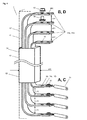
- Fig. 2 shows a busbar 1 '' with five cast in an insulating body 10 line bars 11, within a aligned along a longitudinal axis y line trunk 18 between a first and a second end piece 1A, 1B with connection areas A and B and in a perpendicular thereto aligned line branch 19
- a third end piece 1C extends with a connection region C.
- the conductor rods 11 of the conductor trunk 18 and the adjoining cable branch 19 are cast in a common busbar body 10, preferably in an insulation body of insulating material, such as cast resin or polymer concrete
- the conductor bar 1 "'therefore has the same high quality over the entire area up to each extremity.
- connection areas B and B ' At the second end piece 1B there are provided two connection areas B and B ', at which connections 11B, 11B "of the conductor bars 11 emerge parallel and perpendicular to the busbar axis x from the busbar body 10.
- connections 11B, 11B "of the conductor bars 11 emerge parallel and perpendicular to the busbar axis x from the busbar body 10.
- blind connections which are used as required after installation can be.
- a line branch 19 is led away.
- This line branch 19 can advantageously be guided out of the conduit shaft into a building space.
- the terminals 11C of the conductor bars 11 of the lead 19 with end pieces of connecting lines 31, ..., 35 are connected.
- the end pieces of the connecting leads 31,..., 35 are welded to the conductor rods 11,..., 15 or, as shown, screwed and cast by means of screws 93, whereby a closing head 5 is formed.
- the terminals 11 C with holes 990 be provided, for example, have a thread (see Fig. 11).
- the line trunk 18 may be provided on at least one side with one or more line branches or connection areas.
- the busbars 1 "' can therefore be adapted as needed to any structure of a building and a duct.
- Fig. 2 shows that the insulating body 10 of the busbar 1 "'can be provided with a shield 61 which shields magnetic fields caused by electrical currents to the outside, so that no disturbing effects on the user or electrical equipment remain a coat made of a special sheet or a special foil provided.
- special films are used in the manner known by the names MUMETALL, VITROVAC, VITROPERM.
- shields made of nickel-iron alloys or cobalt-iron alloys are used.
- the described shielding for all busbars 1, 1 ', 1 ", 1'" of the busbar system 100 thus achieves a complete shielding of the energy distribution device up to the consumers.
- Corresponding regulations, such as EMC regulations are therefore always complied with.
- the busbar clutches 9 are provided with shields.
- Fig. 3a shows a preferably designed busbar 1 with U-shaped conductor bars 11 which extend in opposite first and second end pieces 1A, 1B to terminal areas A and B and there are still bent within the busbar body 10 by 90 ° in the same direction.
- the ends of the conductor bars 11 with the Terminals 11A, 11B are parallel to each other and emerge laterally from the busbar body 10.
- a third end piece 1C having terminals 11C in a third terminal area C and third terminals 11C. These were connected in one piece with the conductor rods 11 before casting or welded or screwed with these. This third terminal area C has been shifted to the first terminal area A.
- connection region D In the second connection region B, in turn, a fourth connection region D with five connections or connection pieces 11D is optionally provided, into which connection screws 93 can be inserted.
- connection cable or its cable lugs 31 By means of the terminal screws 93 connection cable or its cable lugs 31 can be tightened.
- the fourth terminals 11D are preferably countersunk in the busbar body 10, so that they can be cast with little effort.
- the busbar 1 can therefore be manufactured without the connection regions C and D or with the connection region C and / or D.
- the connection areas C and / or D are provided centrically or eccentrically on the same or on opposite sides.
- Fig. 3b shows the first and the fifth line rod 11 of the busbar 1 of Fig. 3a in this embodiment have integrally connected first, second and optional third and fourth terminals 11A, 11B and 11C, 11D.
- the Bending is preferably carried out about a bending axis which is parallel to the longitudinal axis of the busbar and parallel to the longer rectangular side 12. As a result, the conductor bars 11 are cast into the busbar body 10.
- Fig. 3a the distances d11 between the individual terminals 11A, 11B are shown, which are freely selectable in a wide range regardless of the diameter d10 of the busbar body 10.
- the terminals 11A, 11B can therefore be spaced so that they can be conveniently connected to the terminals of a subsequent bus bar. Fanning the terminals 11A, 11B is not necessary.
- bus bar 1 can now be provided on the bottom and the top with mounting members 45, such as hooks or the like, so that they are handled advantageously, e.g. can be held with a crane and lowered vertically into a shaft.
- mounting members 45 such as hooks or the like
- Fig. 4 shows a conductor rail 1 according to the invention with four conductor bars 11, the axial and bottom out of the end pieces 1A, 1B outward and outside the busbar body 10 are bent by 90 ° in the same direction and in the connection areas A and B parallel to each other.
- This busbar 1 has the same advantages as the busbar of Fig. 3a , However, since the bus bar body 10 is shortened, the terminals 11A, 11B are more accessible and may be made shorter. Furthermore, the exposed electrical conductors 11 can already be provided with an elasticity which makes it possible to compensate for occurring thermal expansions.
- the terminals 11A, 11B of the busbar of Fig. 3a and Fig. 4 can also be bent in opposite directions, so that the conductor bars are S- or Z-shaped.
- the dotted line symbolizes the extended Busbar body 10 'of Fig. 3a , By choosing the appropriate die can therefore optionally the busbar 1 of Fig. 3a or from Fig. 4 be made.
- Fig. 4 further shows that the ports 11A, 11B are provided with first and second bores 99 and 990.
- the first holes 99 are used to receive screws 98 by means of which the busbar 1 with an adjacent busbar 1 'is connectable.
- the second holes 93 serve to receive terminal screws 93, by means of which connection cable 31 or cable lugs connected thereto can be screwed tight.
- the first and second terminals 11A, 11B therefore additionally serve as third and fourth terminals 11C, 11D, respectively.
- Fig. 5a shows two interconnected busbars 1, 1 'according to Fig. 3a Whose first and second terminals 11A, 11B, which are directed against each other, are connected to each other and to third terminals 11C.
- Fig. 5a further shows a screw 98 and a nut 97 through which terminals 11A, 11B and 11C can be connected together.
- Fig. 5b shows two juxtaposed and overlapping busbars 1, 1 ', whose first and second terminals 11A, 11B, which are aligned parallel to each other, and with third terminals 11C are connected. Due to the relatively large selected distance d11 between the terminals 11A and 11B can be easily intervened with a tool. It is also particularly advantageous that the connections 11A, 11B and 11C face the installer.
- the busbar body 10 are parallel to each other and can be advantageously interconnected. For example, the busbar body 10 to each other complementary moldings that can be moved into each other and hold each other form-fitting. In this case, the busbars 1 can be assembled modularly without further connecting means.
- the terminals 11C which are in the FIGS. 5a and 5b are shown, for example, the connections of a busbar 1C and a busbar branch, which is guided out of the conduit shaft 80 out into a building room (see Fig. 7 ).
- the third terminals 11C may also serve as terminals or lugs connected to flexible leads 31 (see FIG FIG. 3a , Connection area D). All of the ports 11A, 11B, 11C are subsequently potted so that a sealed busbar intersection or termination head between lines 31 results (see FIG Fig. 2 ).
- Fig. 6a shows a conductor rail system 100 according to the invention with busbars 1, 1 ', whose terminals 11A, 11B, as in Fig. 3a shown, directly and firmly connected.
- the busbars 1, 1 ' are provided with mounting elements 45, by means of which the busbars 1, 1' can be transported and / or fixed.
- the mounting elements can also be integrally formed on the busbar body 10.
- the third connection regions C can, as shown, be arranged in the center of the busbars 1, 1 'or eccentrically, if thermal expansions are to be expected. In this case, for example, the embodiment of Fig. 6b realized.
- the connection of the terminals 11A, 11B and optionally additional terminals 11C takes place, for example, as in Fig. 5a shown.
- Fig. 6b shows an inventive busbar system 100 with busbars 1, 1 'according to Fig. 3a whose terminals 11A, 11B are connected to each other by elastic conductors 110.
- a busbar coupling 9 which has a stretchable bellows 90, in which preferably an elastic casting material is inserted.
- Fig. 7 shows a building installation 1000 with a busbar system 100 according to the invention for energy distribution in a building 8, which has several floors 831, 832, 833, 834, in which electrical appliances 51, 52, 53, 54 each to an associated energy consumer, eg a power distributor, Sub-distributor or circuit breaker 21, 22, 23, 24 are connected.
- the busbar system 100 may optionally be composed of the above-described and correspondingly sized busbars 1, 1 ", 1"'.
- the busbar system of Fig. 6b used.
- the busbar system 100 shown comprises four busbars 1, 1 'and a conventional busbar 1 ", which are guided coaxially and vertically upwards in a duct 80.
- the duct 80 is provided adjacent to an outer wall 81 of the building 8 and through a shaft wall 82 inside
- the shaft wall 82 simultaneously forms a building inner wall and is provided with wall openings 820 which each provide access to an associated building floor 831,..., 834.
- the busbars 1, 1 ' form a conduction trunk 18 guided vertically upwards in the duct shaft 80, from which duct branches 19 or third end pieces of the busbars 1, 1' are guided through the wall openings 820 into one of the building floors 831, ..., 834 become.
- the conventional busbar 1 "from Fig. 1 serves to guide electrical energy to the height of the first floor 831.
- the busbar system 100 has a first line branch 19, which is guided through one of the wall opening 820 through to an energy collector 21 in the first floor 831.
- the line trunk 18 of this busbar 1 leads within the duct 80 further to the height of the second floor 832 and is there connected to the following busbar 1, which has a second line branch 19 passing through a wall opening 820 to a power collector 22 in the second floor 832 is guided.
- This busbar 1 leads within the duct 80 further to the height of the third floor 833 and is there connected to the next busbar 1 ', which via a third line branch 19 with a power pickup 23 in the third floor 833 and via the line trunk 18 and a busbar coupling 9 is connected to the last inventive busbar 1.
- the relatively short lead trunk 18 with the two end pieces 13a and 13b is aligned horizontally, while the long Line branch 19 protrudes vertically into the conduit shaft 80 and is guided into the busbar coupling 9.
- the first end piece 13a leads to a power pickup 24 in the fourth floor 834 and the second end piece 13b leads to another building part, not shown here, or into a space on the opposite side of the duct 80.
- the inventive busbar system 100 can therefore be walled in "forever” so that it forms an integral part of the building 8.
- the busbar system 100 therefore has significant advantages in terms of assembly, maintenance, later expansion and in particular also with regard to the building structure and the building management.
- the architect has a component available that can be advantageously integrated into the building and takes up little space to complete.
Abstract
Die Stromschiene (1) umfasst Leitungsstäbe (11),
a) die einen zumindest annähernd rechteckförmigen Querschnitt mit einer längeren Rechteckseite (11) und einer kürzeren Rechteckseite (12) aufweisen;
b) die von einem ersten Anschlussbereich (A) an einem ersten Endstück (1A) der Stromschiene (1, 1') zu wenigstens einem zweiten Anschlussbereich (B) an einem zweiten Endstück (1B) der Stromschiene (1) geführt sind;
c) die endseitig erste und zweite Anschlüsse (11A, 11B) bilden; und
d) die derart in einen Stromschienenkörper (10) eingegossen sind, dass zumindest die ersten und zweiten Anschlüsse (11A, 11B) frei liegen.The busbar (1) comprises conductor bars (11),
a) having an at least approximately rectangular cross-section with a longer side of the rectangle (11) and a shorter side of the rectangle (12);
b) which are guided from a first connection region (A) on a first end piece (1A) of the conductor rail (1, 1 ') to at least one second connection region (B) on a second end piece (1B) of the conductor rail (1);
c) the end-side first and second terminals (11A, 11B) form; and
d) which are cast in a busbar body (10) such that at least the first and second terminals (11A, 11B) are exposed.
Erfindungsgemäss sind die Leitungsstäbe (11) im ersten Anschlussbereich (A) und die Leitungsstäbe (11) im zweiten Anschlussbereich (B) vorzugsweise um 90° je um eine Biegeachse umgebogen, so dass die ersten und zweiten Anschlüsse (11A, 11B) auf die eine oder andere Seite des Stromschienenkörpers (10) ausgerichtet und zur seitlichen Kontaktierung einer weiteren Stromschiene (1') vorgesehen sind.

Description
Die Erfindung betrifft eine Stromschiene und ein Stromschienensystem zur Energieverteilung in einem Gebäude.The invention relates to a busbar and a busbar system for power distribution in a building.
Für die Übertragung von Strom mit hoher Leistung, hoher Sicherheit und Zuverlässigkeit werden Stromschienen als Übertragungsleitungen zwischen Transformatoren, Haupt- und Unterverteilern in Fabrikhallen, Gewerbe- und Verwaltungsgebäuden oder auch als Steigleitungen in Hochbauten eingesetzt. Stromschienen und deren Verwendung sind z.B. in [1], Produktkatalog "Niederspannungs-Schienenverteiler LANZ HE 2.5.2" der LANZ OENSINGEN AG vom September 2009 beschrieben. Stromschienen dieser Art werden auch als Schienenverteiler bezeichnet.For the transmission of power with high performance, high safety and reliability, busbars are used as transmission lines between transformers, main and subdistributors in factory buildings, commercial and administrative buildings or as risers in buildings. Bus bars and their use are e.g. in [1], LANZ OENSINGEN AG's product catalog "Low-voltage busbar trunking system LANZ HE 2.5.2" from September 2009. Busbars of this type are also referred to as busbar trunking.
[2],
Die Leitungsstäbe qualitativ hochwertiger Stromschienen sind in Giessharz oder Epoxyzement bzw. Polymerbeton eingegossen und erreichen dadurch den Schutzgrad IP68. In dieser Ausgestaltung werden die Stromschienen auf Erdbebensicherheit, Schocksicherheit und Funktionserhalt im Brandfall ausgelegt. D.h., weder elektrische, mechanische, thermische oder chemische Einwirkungen, insbesondere auch kein Druckwasser, können die Betriebssicherheit der Stromschienen gefährden. Mit den Stromschienen kann daher ein maximaler Sicherheitsstandard eingehalten werden. Ferner kann ein hoher Standard für den Funktionserhalt im Brandfall, wie F90, eingehalten werden. Oft werden Stromschienen mit einer Abschirmung versehen, mittels der niederfrequente magnetische Wechselfelder abgeschirmt und Normen der Serie EN 61000 eingehalten werden.The conductor bars of high-quality busbars are cast in cast resin or epoxy cement or polymer concrete and thus achieve the degree of protection IP68. In this embodiment, the busbars are designed for seismic safety, shock resistance and functional integrity in case of fire. That is, neither electrical, mechanical, thermal or chemical effects, especially no pressurized water, can endanger the operational safety of the busbars. With the busbars, therefore, a maximum safety standard can be maintained. Furthermore, a high standard for functional integrity in case of fire, such as F90, can be maintained. Busbars are often shielded, shielding low-frequency alternating magnetic fields and compliant with EN 61000 series standards.
Stromschienen sind ferner aus [3],
Aus [4],
Allgemein ist zu beachten, dass ein Energieversorgungsstrang stets so gut ist wie sein schwächstes Glied. Dies gilt für die Funktionsfähigkeit, aber auch für alle wichtigen Nebenfaktoren, wie die Einhaltung der Eigenschaften, die durch die Normen IP 68, F90 (Funktionserhalt im Brandfall) und EN 61000 (EMV- Verträglichkeit) gefordert sind. Der korrekten Verbindung der Stromschienen kommt daher eine grosse Bedeutung zu.In general, it should be noted that a power line is always as good as its weakest link. This applies not only to functionality but also to all important secondary factors, such as compliance with the properties required by the standards IP 68, F90 (functional integrity in the event of fire) and EN 61000 (EMC compatibility). The correct connection of the busbars is therefore of great importance.
Zur Verbindung von zwei Stromschienen gemäss
Diese Art der Verbindung, die aufgrund des geringen Abstands zwischen den einzelnen Leitern der Stromschiene gewählt wird, ist daher aufwendig und kostspielig.This type of connection, which is chosen because of the small distance between the individual conductors of the busbar, is therefore complicated and expensive.
Nachteilig ist ferner, dass die Verbindungen zwischen den Stromschienen in einem schwierigen Umfeld, z.B. in einem Leitungsschacht, nicht leicht erstellt werden können. Ferner sind Verzweigungen nicht leicht realisierbar. Zur Realisierung eines Leitungsgastes kann die Stromschiene von
Zu beachten ist ferner, dass die Fertigung der Stromschienen von
Weiterhin ist die Stromschiene von
Die Installation dieser Stromschienen insbesondere in einem Leitungsschacht ist daher nicht leicht möglich. Entsprechende Stromschienensysteme sind daher nur mit relativ grossem Aufwand realisierbar.The installation of these busbars, especially in a duct is therefore not easily possible. Corresponding busbar systems are therefore feasible only with relatively great effort.
Der vorliegenden Erfindung liegt daher die Aufgabe zugrunde, eine verbesserte Stromschiene und ein verbessertes Stromschienensystem zu schaffen.The present invention is therefore based on the object to provide an improved busbar and an improved busbar system.
Insbesondere ist eine Stromschiene zu schaffen, die einfach und kostengünstig herstellbar und einfach handhabbar ist.In particular, a busbar is to create, which is simple and inexpensive to produce and easy to handle.
Die Stromschiene soll in einfacher Weise mit weiteren Stromschienen oder mit weiteren elektrischen Vorrichtungen, insbesondere Anschlusskabel, verbindbar sein und dazu mit vorteilhaften Anschluss- und Verbindungsmöglichkeiten realisierbar sein.The busbar should be in a simple manner with other busbars or with other electrical devices, in particular connection cable, connectable and to be realized with advantageous connection and connection options.
Auf die Verwendung aufwändiger Verbindungsvorrichtungen und entsprechender Verbindungsarbeiten soll verzichtet werden können. Insbesondere soll auf die Verwendung eines Drehmomentschlüssels verzichtet werden können. Trotzdem soll die Qualität der resultierenden Verbindungen verbessert und zuverlässige realisiert werden. Die Verbindungen sollen auch nach mehrmaliger Demontage und Montage der Verbindungsvorrichtung bzw. Stromschienenkupplung mit unverändert hoher Qualität erstellt werden können.On the use of complex connecting devices and appropriate connection should be able to do without. In particular, should be dispensed with the use of a torque wrench. Nevertheless, the quality of the resulting compounds should be improved and realized reliably. The connections should also can be created with unchanged high quality after repeated disassembly and assembly of the connecting device or busbar coupling.
Die Anschlüsse der Stromschienen sollen optisch leicht kontrolliert und gewartet werden können. Ferner soll für die Montage der Anschlüsse genügend Raum zur Verfügung stehen. Die Kontaktierung soll in hoher Qualität mit hohem und gleichmässigem Anpressdruck realisierbar sein.The connections of the busbars should be visually easy to control and maintain. Furthermore, should be available for the installation of the connections enough space. The contacting should be possible in high quality with high and uniform contact pressure.
Ferner ist ein Stromschienensystem zu schaffen, das unter Wahrung eines einheitlich hohen Qualitätsstandards, z.B. Schutzgrad IP 68 und Brandsicherheit F90, mit reduziertem Aufwand und reduzierten Kosten erstellt werden kann.It is also necessary to provide a bus bar system which, while maintaining a uniformly high quality standard, e.g. Degree of protection IP 68 and fire safety F90, with reduced effort and reduced costs can be created.
Dazu sollen die Stromschienen auch in einem schwierigen und beengten Umfeld vorteilhaft gehandhabt werden können.For this purpose, the busbars should be handled advantageously even in a difficult and cramped environment.
In Leitungsschächten, z.B. in Steigzonen, in denen kritische Raumverhältnisse vorliegen und Wartungsarbeiten nur schwierig durchführbar sind, soll maximale Sicherheit gewährleistet werden. Ferner ist die Zugänglichkeit zu den Leitungen im Leitungsschacht bzw. ein möglichst grosser Sicherheitsabstand zu gewährleisten.In ducts, e.g. in riser zones, where critical space conditions are present and maintenance work is difficult to carry out, maximum safety is to be ensured. Furthermore, the accessibility to the lines in the duct or the greatest possible safety distance must be ensured.
Das erfindungsgemässe Stromschienensystem soll auch dann einen sicheren Betrieb gewährleisten, wenn Temperaturschwankungen auftreten, die gegebenenfalls durch einen Brand verursacht werden.The busbar system according to the invention should also ensure safe operation if temperature fluctuations occur which are possibly caused by a fire.
Diese Aufgabe wird mit einer Stromschiene und einem Stromschienensystem gelöst, welche die in Anspruch 1 bzw. 9 angegebenen Merkmale aufweisen. Vorteilhafte Ausgestaltungen der Erfindung sind in weiteren Ansprüchen angegeben.This object is achieved with a busbar and a busbar system, which have the features specified in
Die erfindungsgemässe Stromschiene umfasst Leitungsstäbe,
- a) die einen zumindest annähernd rechteckförmigen Querschnitt mit einer längeren Rechteckseite und einer kürzeren Rechteckseite aufweisen;
- b) die von einem ersten Anschlussbereich an einem ersten Endstück der Stromschiene zu wenigstens einem zweiten Anschlussbereich an einem zweiten Endstück der Stromschiene geführt sind;
- c) die endseitig erste und zweite Anschlüsse bilden; und
- d) die derart in einen Stromschienenkörper eingegossen sind, dass zumindest die ersten und zweiten Anschlüsse frei liegen.
- a) having an at least approximately rectangular cross-section with a longer rectangular side and a shorter side of the rectangle;
- b) which are guided from a first connection region on a first end piece of the conductor rail to at least one second connection region on a second end piece of the conductor rail;
- c) form the end first and second terminals; and
- d) which are cast in a busbar body such that at least the first and second terminals are exposed.
Erfindungsgemäss sind die Leitungsstäbe im ersten Anschlussbereich und die Leitungsstäbe im zweiten Anschlussbereich je um eine Biegeachse umgebogen, so dass die ersten und zweiten Anschlüsse auf die eine oder andere Seite des Stromschienenkörpers ausgerichtet und zur seitlichen Kontaktierung einer weiteren Stromschiene vorgesehen sind.According to the invention, the conductor rods in the first connection region and the conductor rods in the second connection region are each bent around a bending axis so that the first and second connections are aligned with one or the other side of the conductor rail body and provided for laterally contacting another conductor rail.
Die Leitungsstäbe bilden daher zumindest annähernd eine U-oder Z-Form. Die Anschlüsse sind vorzugsweise um 90° gebogen. Eine Biegung kann jedoch vorteilhaft im Bereich von 45° bis 90° erfolgen. Durch diese Ausgestaltungen der Anschlüsse kann die Verbindung von zwei erfindungsgemässen Stromschienen erleichtert werden, die übereinander oder nebeneinander angeordnet sind. Die Anordnung der Stromschienen sich in den Anschlussbereichen überlappend und mit nebeneinander und parallel zueinander ausgerichteten Anschlüssen ist besonders vorteilhaft, da die Anschlüsse bequem mit Verbindungselementen sowie weiteren Stromschienen oder Anschlusskabeln verbunden werden können. Die Stromschiene können z.B. an eine Wand montiert und von der Frontseite her bequem bearbeitet werden. Da die Anschlüsse der Stromschiene vorzugsweise aus derselben Seite der Stromschiene hervortreten, kann diese auch einfach gefertigt werden. Die U-förmigen Leitungsstäbe werden beabstandet voneinander in eine Matrize eingefügt, wonach diese mit Giessharz oder Polymerbeton geführt wird. Die Matrize kann bei dieser Ausgestaltung der Stromschiene besonders einfach ausgebildet sein. Erfindungsgemässe Stromschienen können mit minimalem Aufwand rasch hergestellt werden.The conductor bars therefore form at least approximately a U or Z shape. The connections are preferably bent by 90 °. However, a bend can be made advantageously in the range of 45 ° to 90 °. These embodiments of the connections, the connection of two inventive bus bars are facilitated, which are arranged one above the other or side by side. The arrangement of the busbars overlapping in the connection areas and with connections arranged side by side and parallel to one another is particularly advantageous since the connections can be conveniently connected to connecting elements as well as further busbars or connecting cables. For example, the busbar can be mounted on a wall and easily handled from the front. Since the connections of the busbar preferably emerge from the same side of the busbar, this can also be easily manufactured. The U-shaped conductor bars are spaced from each other inserted into a die, after which it is performed with cast resin or polymer concrete. The die can be made particularly simple in this embodiment of the busbar. Bus bars according to the invention can be produced quickly with minimal effort.
Vorzugsweise sind die Leitungsstäbe derart gebogen, dass der Abstand d11 zwischen benachbarten Leitungsstäben ausserhalb des Stromschienenkörpers um einen Faktor n grösser ist, als der Abstand d111 zwischen benachbarten Leitungsstäben innerhalb des Stromschienenkörpers, wobei der Faktor n vorzugsweise in einem Bereich zwischen 1.5 und 5 liegt.Preferably, the conductor bars are bent in such a way that the distance d11 between adjacent conductor bars outside the bus bar body is greater by a factor n than the distance d111 between adjacent conductor bars within the conductor bar body, wherein the factor n is preferably in a range between 1.5 and 5.
Die Biegung der Leitungsstäbe um die jeweilige Biegeachse erfolgt vorzugsweise um dasselbe Mass. Die Biegeachsen sind vorzugsweise in einem gleichmässigen Raster voneinander beanstandet und legen vorzugsweise in einer Ebene. Der Abstand zwischen zwei Biegeachsen bildet vorzugsweise die Hypotenuse eines Dreiecks, dessen Katheten die Abstände d11 und d111 sind.The bending of the conductor bars around the respective bending axis preferably takes place by the same amount. The bending axes are preferably spaced from one another in a uniform grid and preferably lie in one plane. The distance between two bending axes preferably forms the hypotenuse of a triangle whose catheters are the distances d11 and d111.
Die Biegeachsen der Leitungsstäbe können wahlweise innerhalb oder ausserhalb des Stromschienenkörpers liegen. Alternativ kann auch ein Teil der Biegeachsen innerhalb und ein weiterer Teil der Biegeachsen ausserhalb des Stromschienenkörpers liegen.The bending axes of the conductor bars can be located either inside or outside the busbar body. Alternatively, a part of the bending axes can be inside and a further part of the bending axes outside of the busbar body.
Die Abstände der Anschlüsse in den beiden Anschlussbereichen A und B, die vorzugsweise innerhalb eines gleichmässigen Rasters liegen, werden derart gewählt, dass Verbindungsgarnituren, wie Schrauben und Schraubenmuttern, individuell für jedes Paar von Anschlüssen von zwei Stromschienen bequem montiert werden können. Dabei sollen für jedes Paar von Anschlüssen eine oder mehrere Verbindungschrauben montierbar sein, sodass eine optimale Kontaktierung der zu verbindenden Leiterpaare resultiert.The distances of the terminals in the two terminal areas A and B, which are preferably within a uniform grid, are selected such that connecting sets, such as screws and nuts, individually for each pair of Connections of two busbars can be easily mounted. In this case, one or more connecting screws should be mountable for each pair of terminals, so that an optimal contact of the conductor pairs to be connected results.
Die relativ weit voneinander beabstandeten Anschlüsse können daher vor der Installation in einfacher Weise optisch kontrolliert und gereinigt werden. Die Anschlüsse werden sodann individuell anhand von einer oder mehreren Schrauben verschraubt, sodass für jede einzelne Verbindung eine optimale Kontaktierung gewährleistet ist. Eine aufwändige Verbindungsvorrichtung sowie die Notwendigkeit der Verwendung eines Drehmomentschlüssels entfallen.The relatively widely spaced ports can therefore be optically controlled and cleaned prior to installation in a simple manner. The connections are then bolted individually by means of one or more screws, so that for each connection optimal contact is guaranteed. A complex connecting device and the need to use a torque wrench omitted.
Die Anschlüsse sind unbearbeitete Endstücke der Leitungsstäbe oder bearbeitete Endstücke der Leitungsstäbe, die wenigstens eine erste Bohrung, gegebenenfalls eine Gewindebohrung, zur Aufnahme einer Verbindungsschraube aufweisen. Zusätzlich ist vorzugsweise eine zweite Bohrung, gegebenenfalls eine Gewindebohrung, zur Aufnahme einer Anschlussschraube vorgesehen, mittels der eine Anschlusskabel, gegebenenfalls ein Kabelschuh eines Anschlusskabels montierbar ist. Die ersten beiden Anschlussbereiche von erfindungsgemässen Stromschienen können daher mit weiteren Stromschienen sowie mit weiteren Anschlüssen, Stromschienen oder Anschlusskabeln, verbunden werden. Auf diese Weise können drei Stromschienen bedarfsweise zu einem T-Stück verbunden werden. Ordnungsgemäss kann daher ein beliebig verzweigtes Stromschienensystem aufgebaut werden, das insbesondere in vertikalen Leitungsschächten von Gebäuden vorteilhaft einsetzbar ist.The connections are unprocessed end pieces of the conductor rods or machined end pieces of the conductor rods, which have at least one first bore, possibly a threaded bore, for receiving a connecting screw. In addition, a second bore, optionally a threaded bore, is preferably provided for receiving a connecting screw, by means of which a connecting cable, optionally a cable lug of a connecting cable can be mounted. The first two connection regions of busbars according to the invention can therefore be connected to further busbars as well as to further connections, busbars or connecting cables. In this way, three busbars can be connected as needed to a tee. Properly, therefore, an arbitrarily branched busbar system can be constructed, which is advantageously used in particular in vertical duct shafts of buildings.
Zur Bildung eines Stromschienensystems werden die erfindungsgemässen Stromschienen vorzugsweise mit einem dritten und/oder einem vierten Anschlussbereich versehen.To form a busbar system, the busbars according to the invention are preferably provided with a third and / or a fourth connection region.
Die ersten und zweiten Anschlüsse werden an der Frontseite und/oder der Rückseite des vorzugsweise quaderförmigen Stromschienenkörpers angeordnet. Die dritten und/oder vierten Anschlüsse werden um 90° versetzt an einer der Seiten zwischen der Frontseite oder Rückseite des Stromschienenkörpers angeordnet.The first and second connections are arranged on the front side and / or the rear side of the preferably cuboid conductor rail body. The third and / or fourth terminals are arranged offset by 90 ° on one of the sides between the front side or rear side of the busbar body.
Die dritten und oder vierten Anschlüsse sind mit den Leitungsstäben vorzugsweise einstückig, durch eine Schraubverbindung oder durch Schweissen verbunden und vorzugsweise als Stäbe oder Schraubanschlüsse ausgebildet. Die vierten Anschlüsse in Form von Schraubanschlüssen werden vorzugsweise im Stromschienenkörper versenkt, sodass sie mit geringem Aufwand dicht abgeschlossen und bedarfsweise freigelegt werden können. Diese Anschlüsse können daher nicht nur bei der Installation, sondern auch zu einem späteren Zeitpunkt zur Erweiterung des Stromschienensystems verwendet werden. Die im Stromschienenkörper eingegossenen Schraubanschlüsse können vorteilhaft für die Montage von Anschlusskabeln verwendet werden.The third and or fourth terminals are preferably integral with the conductor bars, connected by a screw connection or by welding, and preferably formed as rods or screw terminals. The fourth terminals in the form of screw terminals are preferably countersunk in the busbar body, so that they can be tightly sealed with little effort and, if necessary, be exposed. These connections can therefore be used not only during installation, but also at a later date to expand the busbar system. The screwed in in the busbar body screw can be used advantageously for the installation of connecting cables.
In vorzugsweisen Ausgestaltungen ist der Stromschienenkörper einstückig mit wenigstens einem Formelement oder mit wenigstens einem eingesetzten Halteelement versehen, das an Formelemente oder Halteelemente benachbarter Stromschienen oder an Haltevorrichtungen oder Werkzeuge ankoppelbar ist, mittels denen die Stromschiene manipulierbar oder fixierbar ist. Z.B. ist der Stromschienenkörper an der Oberseite oder der Unterseite mit einem Haken versehen, der von einem Kran erfasst werden kann, mittels dessen die Stromschiene in einen Leitungsschacht abgesenkt werden kann. Auf diese Weise kann ein Stromschienensystem mit geringem Aufwand rasch innerhalb eines Gebäudes bzw. innerhalb eines Leitungsschachts aufgebaut werden.In preferred embodiments, the busbar body is integrally provided with at least one mold element or at least one inserted holding element which can be coupled to form elements or holding elements of adjacent busbars or to holding devices or tools, by means of which the busbar can be manipulated or fixed. For example, the busbar body is provided at the top or bottom with a hook that can be detected by a crane, by means of which the busbar can be lowered into a duct. In this way, a busbar system with little effort quickly within a building or within a duct can be built.
Innerhalb des Stromschienensystems werden wenigstens zwei benachbarte Stromschienen durch eine Stromschienenkupplung miteinander verbunden, die wenigstens einen deformierbaren elektrischen Leiter aufweist, durch den die Anschlüsse der einander zugewandten Stromschienen derart miteinander verbunden sind, dass Temperaturdehnungen der Stromschienen kompensierbar sind.Within the busbar system, at least two adjacent busbars are connected to one another by a busbar coupling which has at least one deformable electrical conductor, through which the terminals of the mutually facing busbars are connected to one another such that thermal expansions of the busbars can be compensated.
Der wenigstens eine elastische elektrische Leiter ist vorzugsweise als elastischer Metallbügel oder als Metallband ausgebildet, das gegebenenfalls eine Laminatstruktur mit mehreren metallenen Lagen aufweist.The at least one elastic electrical conductor is preferably formed as an elastic metal strap or as a metal band, which optionally has a laminate structure with a plurality of metal layers.
Die Kopplungsstellen zwischen den Stromschienen werden vorzugsweise durch eine Kopplungshülse überdeckt, welche auf jeder Seite mit dem zugehörigen Endstück der betreffenden Stromschiene vorzugsweise durch eine Schweissnaht, eine Gussverbindung, eine Rastvorrichtung oder eine formschlüssige Pressverbindung dicht abschliessend verbunden ist.The coupling points between the busbars are preferably covered by a coupling sleeve, which is connected on each side with the associated end piece of the respective busbar preferably by a weld, a cast connection, a locking device or a positive press connection tightly sealing.
Vorzugsweise ist die Kopplungshülse als dehnbarer Balg ausgebildet, der den Bewegungen der Endstücke der Stromschienen folgen kann. Vorzugsweise ist die Kopplungshülse mit einer elastischen Dichtungsmasse, vorzugsweise einer Silikonmasse, zumindest teilweise gefüllt und dadurch dicht abgeschlossen.Preferably, the coupling sleeve is formed as a stretchable bellows, which can follow the movements of the end pieces of the busbars. Preferably, the coupling sleeve with an elastic sealant, preferably a silicone mass, at least partially filled and thereby sealed.
In einem Leitungsschacht werden die Endstücke der Stromschienen, von denen Abzweigungen aus dem Leitungsschacht hinaus geführt werden vorzugsweise je von einer Stütze oder einem Element der Schachtmauer auf konstanter Höhe gehalten. Das elastisch mit der benachbarten Stromschiene verbundene Ende der kann sich hingegen in Funktion der Temperatur nach oben dehnen.In a duct, the end pieces of the busbars, from which branches are led out of the duct shaft preferably each held by a support or an element of the manhole wall at a constant height. The elastically connected to the adjacent busbar end, however, can stretch upwards in function of the temperature.
Stromschienen oder Kabel, die mit den dritten und oder vierten Anschlüssen verbunden und durch eine Öffnung aus dem Leitungsschacht hinaus geführt werden, sind daher vorzugsweise exzentrisch beim ersten oder zweiten Anschlussbereich angeordnet, der auf konstanter Höhe gehalten wird. Beim Auftreten von Temperaturdehnungen werden auf diese Stromschienen und Kabel keine Kräfte ausgeübt.Bus bars or cables, which are connected to the third and or fourth terminals and out through an opening out of the duct, are therefore preferably arranged eccentrically at the first or second connection area, which is kept at a constant height. When thermal expansions occur no forces are exerted on these busbars and cables.
Das Stromschienensystem mit den erfindungsgemässen Stromschienen kann daher vorteilhaft für Gebäudeinstallationen insbesondere in Gebäuden Leitungsschächten verwendet werden, um von den Stromschienen abgezweigte elektrische Leitungen, die als Stromschienen oder Kabel ausgebildet sind, in vom Leitungsschacht getrennte Räume zu Energieabnehmern oder Energieverteilern zu führen.The busbar system with the busbars according to the invention can therefore be used advantageously for building installations, in particular in building ducts, in order to guide branched-off electrical conductors, which are designed as busbars or cables, in rooms separated from the conduit to energy consumers or energy distributors.
Innerhalb des Leitungsschachts verlaufen somit nur die Stromschienen mit den vollständig eingegossenen Leitungsstäben und Kupplungsvorrichtungen. Das Auftreten einer Betriebsstörung des elektrischen Systems innerhalb des Leitungsschachts kann daher praktisch ausgeschlossen werden. Die Installation der Stromschiene innerhalb des Leitungsschachts ist zudem weitestgehend immun gegenüber Störungen benachbarter Systeme, z.B. eines Wasserrohrbruchs innerhalb des Leitungsschachts oder gegen Feuer. Der Funktionserhalt der Energieversorgung innerhalb des Gebäudes bleibt auch im Katastrophenfall zumindest über die erforderliche Dauer gewährleistet.Thus, only the busbars with the completely cast-in conductor bars and coupling devices run within the duct. The occurrence of a malfunction of the electrical system within the duct can therefore be virtually ruled out. The installation of the busbar within the duct is also largely immune to interference from adjacent systems, e.g. a water pipe break inside the duct or against fire. The functional integrity of the energy supply within the building remains guaranteed even in the event of a disaster, at least for the required duration.
Das erfindungsgemässe Stromschienensystem ist homogen ausgebildet und frei von Schwachstellen. Gewährleistet sind die uneingeschränkte Funktionsfähigkeit, aber auch zumindest die Einhaltung der Eigenschaften, die durch die Normen IP 68 (u.a. Schutz gegen Druckwasser), F90 (Funktionserhalt im Brandfall) und EN 61000 (EMV- Verträglichkeit) gefordert sind, bis zum elektrischen Verbraucher.The inventive busbar system is formed homogeneously and free of weak points. Guaranteed are the unrestricted functionality, but also at least the observance of the properties, which by the standards IP 68 (among other things protection against pressurized water), F90 (function maintenance in the Fire) and EN 61000 (EMC compatibility) are required, up to the electrical consumer.
Nachfolgend wird die Erfindung anhand von Zeichnungen näher erläutert. Dabei zeigt:
- Fig. 1
- eine bekannte Stromschiene 1" mit fünf in
einem Isolationskörper 10 eingebetteten Leitungsstäben 11, die inEndstücken - Fig. 2
- eine Stromschiene 1'" mit fünf in
einem Isolationskörper 10 eingegossenen Leitungsstäben 11, die innerhalb eines entlang einer Längsachse x ausgerichteten Leitungsstamms 18 zu zwei erstenEndstücken Endstück 1C mit einem Anschlussbereich C verlaufen; - Fig. 3a
eine Stromschiene 1mit U-profilförmigen Leitungsstäben 11, die in den Anschlussbereichen A bzw. B zur Seite gebogen sind und seitlich ausdem Stromschienenkörper 10 hervortreten;- Fig. 3b
- den ersten und
den fünften Leitungsstab 11der Stromschiene 1 vonFig. 3a , die einstückig miteinander verbundene Anschlüsse 11A, 11B,11C und 11D aufweist; - Fig. 4
- eine erfindungsgemässe Stromschiene 1
mit vier Leitungsstäben 11, die unten und oben axial ausden Endstücken - Fig. 5a
- die
Endstücke Fig. 3a , deren erste bzw.zweite Anschlüsse mit dritten Anschlüssen 11C verbunden sind; - Fig. 5b
- die
Endstücke Fig. 3a , deren erste bzw.zweite Anschlüsse mit dritten Anschlüssen 11C verbunden sind; - Fig. 6a
- eine erfindungsgemässe Gebäudeinstallation 1000 mit fest miteinander verbundenen Stromschienen 1, 1', gemäss
Fig. 3a ; - Fig. 6b
- eine erfindungsgemässe Gebäudeinstallation 1000 mit elastisch miteinander verbundenen Stromschienen 1, 1' gemäss
Fig. 3a ; und - Fig. 7
ein erfindungsgemässes Stromschienensystem 100 für die Energieverteilung in einem Gebäude 8 bzw.eine Gebäudeinstallation 1000 mit mehrerenStromschienen 1, die durch elastische Stromschienenkupplungen 9 miteinander verbunden sind und dieje drei Endstücke einem Leitungsschacht 80 geführten Leitungsstamm 18 und Leitungsäste 19 bilden, diedurch Maueröffnungen 820 hindurch je ineine Gebäudeetage 831, ..., 834 geführt werden;
- Fig. 1
- a known
busbar 1 "with five embedded in an insulatingbody 10line rods 11, which are guided inend pieces unprocessed terminals - Fig. 2
- a busbar 1 '"with five in an insulating
body 10 cast-in conductor bars 11, within a aligned along a longitudinal axis xline trunk 18 to twofirst end pieces third end piece 1C extend with a connection region C; - Fig. 3a
- a
busbar 1 with U-shaped conductor bars 11, which are bent in the connection areas A and B to the side and emerge laterally from thebusbar body 10; - Fig. 3b
- the first and the
fifth line rod 11 of thebusbar 1 ofFig. 3a having integrally connectedterminals - Fig. 4
- a
bus bar 1 according to the invention with fourconductor bars 11, which come out of theend pieces - Fig. 5a
- the
end pieces interconnected busbars 1, 1 'according toFig. 3a whose first andsecond terminals third terminals 11C; - Fig. 5b
- the
end pieces interconnected busbars 1, 1 'according toFig. 3a whose first andsecond terminals third terminals 11C; - Fig. 6a
- an
inventive building installation 1000 with firmlyinterconnected busbars 1, 1 ', according toFig. 3a ; - Fig. 6b
- an
inventive building installation 1000 with elasticallyinterconnected busbars 1, 1 'according toFig. 3a ; and - Fig. 7
- an
inventive busbar system 100 for power distribution in a building 8 or abuilding installation 1000 withmultiple busbars 1, which are connected byelastic busbar couplings 9 and each having threeend pieces duct shaft trunk 18 18th andLeitäste 19 form, which are guided throughwall openings 820 through each in abuilding floor 831, ..., 834;
Am zweiten Endstück 1B sind zwei Anschlussbereiche B und B' vorgesehen, an denen Anschlüsse 11B, 11B" der Leitungsstäbe 11 parallel und senkrecht zur Stromschienenachse x aus dem Stromschienenkörper 10 austreten. Z.B. ist es auch möglich Blindanschlüsse vorzusehen, die nach der Installation bei Bedarf genutzt werden können.At the
Vom Leitungsstamm 18 der Stromschienen 1 wird ein Leitungsast 19 weggeführt. Dieser Leitungsast 19 kann vorteilhaft aus dem Leitungsschacht hinaus in einen Gebäuderaum geführt werden. Dort sind die Anschlüsse 11C der Leitungsstäbe 11 des Leitungsasts 19 mit Endstücken von Anschlussleitungen 31, ..., 35 verbunden. Die Endstücke der Anschlussleitungen 31, ..., 35 werden mit den Leitungsstäben 11, ..., 15 verschweisst oder, wie gezeigt, mittels Schrauben 93 verschraubt und vergossen, wodurch ein Abschlusskopf 5 gebildet wird. Zur Aufnahme der Schrauben 93 können die Anschlüsse 11C mit Bohrungen 990 versehen werden, die z.B. ein Gewinde aufweisen (siehe Fig. 11).From
Der Leitungsstamm 18 kann auf wenigstens einer Seite mit einer oder mehreren Leitungsästen bzw. Anschlussbereichen versehen sein. Die Stromschienen 1"' können daher bedarfsweise an jede Struktur eines Gebäudes und eines Leitungsschachts angepasst werden können.The
Zwischen den ersten beiden Endstücken 1A, 1B ist optional ein drittes Endstück 1C mit Anschlüssen 11C in einem dritten Anschlussbereich C und dritten Anschlüssen 11C vorgesehen. Diese wurden vor dem Giessen einstückig mit den Leitungsstäben 11 verbunden oder mit diesen verschweisst oder verschraubt. Dieser dritte Anschlussbereich C wurde zum ersten Anschlussbereich A hin verschoben.Between the first two
Beim zweiten Anschlussbereich B ist wiederum optional ein vierter Anschlussbereich D mit fünf Anschlüssen bzw. Anschlussstutzen 11D vorgesehen, in die Anschlussschrauben 93 einsetzbar sind. Mittels der Anschlussschrauben 93 können Anschlusskabel bzw. deren Kabelschuhe 31 fest gezogen werden. Die die vierten Anschlüsse 11D werden vorzugsweise im Stromschienenkörper 10 versenkt, sodass sie mit geringem Aufwand vergossen werden können.In the second connection region B, in turn, a fourth connection region D with five connections or
Wahlweise kann die Stromschiene 1 daher ohne die Anschlussbereiche C und D oder mit Anschlussbereich C und/oder D gefertigt werden. Die Anschlussbereiche C und/oder D werden zentrisch oder exzentrisch auf derselben oder auf gegenüberliegenden Seiten vorgesehen.Optionally, the
Die Leitungsstäbe 11, die einen zumindest annähernd rechteckförmigen Querschnitt mit einer längeren Rechteckseite 11 und einer kürzeren Rechteckseite 12 können in einfacher Weise gefertigt, d.h. zugeschnitten und gebogen werden. Die Biegung erfolgt vorzugsweise um eine Biegeachse, die parallel zur Längsachse der Stromschiene und parallel zur längeren Rechteckseite 12 verläuft. In der Folge werden die Leitungsstäbe 11 in den Stromschienenkörper 10 eingegossen.The conductor bars 11, which have an at least approximately rectangular cross-section with a longer
In
Ferner kann die Stromschiene 1 nun an der Unterseite und der Oberseite mit Montageelementen 45, wie Haken oder dergleichen, versehen werden, sodass sie vorteilhaft gehandhabt, z.B. mit einem Kran gehalten und senkrecht in einen Schacht abgesenkt werden kann.Further, the
Die Anschlüsse 11C, die in den
Das gezeigte Stromschienensystem 100 umfasst vier Stromschienen 1, 1' und eine konventionelle Stromschiene 1", die in einem Leitungsschacht 80 koaxial und vertikal nach oben geführt sind. Der Leitungsschacht 80 ist angrenzend an eine Aussenwand 81 des Gebäudes 8 vorgesehen und durch eine Schachtwand 82 innerhalb des Gebäudes 8 weiter begrenzt. Die Schachtwand 82 bildet gleichzeitig eine Gebäudeinnenwand und ist mit Maueröffnungen 820 versehen, die je einen Zugang zu einer zugehörigen Gebäudeetage 831, ..., 834 schaffen.The
Die Stromschienen 1, 1' bilden einen im Leitungsschacht 80 vertikal nach oben geführten Leitungsstamm 18, von dem Leitungsäste 19 bzw. dritte Endstücke der Stromschienen 1, 1' durch die Maueröffnungen 820 hindurch je in eine der Gebäudeetagen 831, ..., 834 geführt werden. Die konventionelle Stromschiene 1" von
Vorzugsweise sind wenigstens zwei der Stromschienen 1, 1' durch eine elastische Stromschienenkupplung 9 miteinander verbunden, die wenigstens einen deformierbaren elektrischen Leiter 110 aufweist, durch den die Anschlussbereiche A, B der einander zugewandten Endstücke 1A, 1B der beiden Stromschienen 1, 1' derart miteinander verbunden sind, dass auftretende Temperaturdehnungen der Stromschienen 1, 1' kompensiert werden.Preferably, at least two of the
Das Stromschienensystem 100 weist einen ersten Leitungsast 19 auf, der durch eine der Maueröffnung 820 hindurch zu einem Energieabnehmer 21 in der ersten Etage 831 geführt ist. Der Leitungsstamm 18 dieser Stromschiene 1 führt innerhalb des Leitungsschachts 80 weiter auf die Höhe der zweiten Etage 832 und ist dort mit der nachfolgenden Stromschiene 1 verbunden, die einen zweiten Leitungsast 19 aufweist, der durch eine Maueröffnung 820 zu einem Energieabnehmer 22 in der zweiten Etage 832 geführt ist. Diese Stromschiene 1 führt innerhalb des Leitungsschachts 80 weiter auf die Höhe der dritten Etage 833 und ist dort mit der nächsten Stromschiene 1' verbunden, die über einen dritten Leitungsast 19 mit einem Energieabnehmer 23 in der dritten Etage 833 und über den Leitungsstamm 18 und eine Stromschienenkupplung 9 mit der letzten erfindungsgemässen Stromschiene 1 verbunden ist. Der relativ kurze Leitungsstamm 18 mit den beiden Endstücken 13a und 13b ist horizontal ausgerichtet, während der lange Leitungsast 19 vertikal in den Leitungsschacht 80 hineinragt und in die Stromschienenkupplung 9 hineingeführt ist. Das erste Endstück 13a führt zu einem Energieabnehmer 24 in der vierten Etage 834 und das zweite Endstück 13b führt zu einem weiteren hier nicht dargestellten Gebäudeteil oder in einen Raum auf der gegenüberliegenden Seite des Leitungsschachts 80.The
Innerhalb des Leitungsschachts 80 befinden sich somit nur vergossene Stromschienen 1', 1 und vergossene Stromschienenkupplungen 9. Die an die Leitungsäste 19 bzw. dritten Endstücke 1C angeschlossenen Abschlussköpfe 5 sind ausserhalb des Leitungsschachts 80 angeordnet und sind vorzugsweise ebenfalls vergossen, sodass nur die isolierten Kabel 31, ..., 35 in die Energieabnehmer 21, 22, 23, 24 hineingeführt werden. Innerhalb des Leitungsschachts 80 ist daher der maximale Sicherheitsgrad, z.B. IP 68, gewährleistet. Mit Systemstörungen ist innerhalb des Leitungsschachts 80 auch dann nicht zu rechnen, falls ein Wasserrohrbruch auftreten sollte. Im Falle eines Feuers wird der maximal mögliche Funktionserhalt gewährleistet. Da keine Anschlusskästen, Anschlussstellen oder weitere Schwachstellen innerhalb des Leitungsschachts 80 vorhanden sind, können Störungen durch mangelhafte Kontaktierung, Oxidation, Wassereinbruch oder Feuer praktisch ausgeschlossen werden.Within the
Durch die elastischen Stromschienenkupplungen 9 werden Temperaturdehnungen aufgefangen, sodass selbst im Brandfall keine störenden Kräfte auf das Stromschienensystem 100 einwirken. Die Leitungsäste 19 bzw. die dritten Endstücke 1C, die vorzugsweise auf einem Mauerstück oder einem Ausleger abgestützt sind, bleiben daher beim Auftreten von Temperaturdehnungen unbewegt, weshalb auf daran anschliessende Kontakte kein Zug oder Druck ausgeübt wird.By the
Sofern keine Erweiterung des Stromnetzes erforderlich ist, muss nach der Installation der Stromschienen 1 kaum mehr in den Leitungsschacht 80 eingegriffen werden. Das erfindungsgemässe Stromschienensystem 100 kann daher "ewig" eingemauert werden, sodass es einen festen Bestandteil des Gebäudes 8 bildet.If no expansion of the power grid is required, it is hardly necessary to intervene in the
Nach der Installation der Stromschienen 1 können notwendige Wartungsarbeiten und Modifikationen bequem in den Gebäudeetagen 831, ..., 834 durchgeführt werden. Für Erweiterungen der Gebäudeinstallation 1000 werden gegebenenfalls Blindanschlüsse der Stromschienen 1 freigelegt und genutzt.After the installation of the
Das erfindungsgemässe Stromschienensystem 100 weist daher hinsichtlich der Montage, der Wartung, der späteren Erweiterung und insbesondere auch hinsichtlich der Gebäudestruktur und des Gebäudemanagements wesentliche Vorteile auf. Dem Architekten steht ein Bauteil zur Verfügung, welches vorteilhaft in das Gebäude integriert werden kann und dazu nur wenig Raum in Anspruch nimmt.The
-
[1]
Produktkatalog "Niederspannungs-Schienenverteiler LANZ HE 2.5.2" der LANZ OENSINGEN AG vom September 2009 Product catalog "Low-voltage busbar trunking system LANZ HE 2.5.2" from LANZ OENSINGEN AG from September 2009 -
[2]
EP1928066A2 EP1928066A2 -
[3]
Produktkatalog von Eta-com: "Cast Resin Insulated Busway System", 27.11.2014 Product catalog from Eta-com: "Cast Resin Insulated Busway System", 27.11.2014 -
[4]
E-LINE MK Busbar Systems 100-160-225A, www.eae.com.tr E-LINE MK Busbar Systems 100-160-225A, www.eae.com.tr
Claims (15)
dadurch gekennzeichnet, dass die Leitungsstäbe (11) im ersten Anschlussbereich (A) und die Leitungsstäbe (11) im zweiten Anschlussbereich (B) vorzugsweise um 90° je um eine Biegeachse umgebogen sind, so dass die ersten und zweiten Anschlüsse (11A, 11B) auf die eine oder andere Seite des Stromschienenkörpers (10) ausgerichtet und zur seitlichen Kontaktierung einer weiteren Stromschiene (1') vorgesehen sind.
characterized in that the conductor rods (11) in the first connection region (A) and the conductor rods (11) in the second connection region (B) are preferably bent by 90 ° about a bending axis, so that the first and second connections (11A, 11B) aligned on one or the other side of the busbar body (10) and for the lateral contacting of a further busbar (1 ') are provided.
Priority Applications (1)
| Application Number | Priority Date | Filing Date | Title |
|---|---|---|---|
| EP15179401.3A EP3125385A1 (en) | 2015-07-31 | 2015-07-31 | Bus bar and bus bar system |
Applications Claiming Priority (1)
| Application Number | Priority Date | Filing Date | Title |
|---|---|---|---|
| EP15179401.3A EP3125385A1 (en) | 2015-07-31 | 2015-07-31 | Bus bar and bus bar system |
Publications (1)
| Publication Number | Publication Date |
|---|---|
| EP3125385A1 true EP3125385A1 (en) | 2017-02-01 |
Family
ID=53773329
Family Applications (1)
| Application Number | Title | Priority Date | Filing Date |
|---|---|---|---|
| EP15179401.3A Withdrawn EP3125385A1 (en) | 2015-07-31 | 2015-07-31 | Bus bar and bus bar system |
Country Status (1)
| Country | Link |
|---|---|
| EP (1) | EP3125385A1 (en) |
Cited By (2)
| Publication number | Priority date | Publication date | Assignee | Title |
|---|---|---|---|---|
| DE202017102148U1 (en) | 2017-04-11 | 2017-05-17 | Zurecon Ag | Busbar and busbar system |
| CN108336706A (en) * | 2018-03-09 | 2018-07-27 | 威腾电气集团股份有限公司 | Air-type bus duct and multi-functional end |
Citations (10)
| Publication number | Priority date | Publication date | Assignee | Title |
|---|---|---|---|---|
| JPS426458Y1 (en) * | 1964-10-23 | 1967-03-28 | ||
| US3466745A (en) * | 1965-05-18 | 1969-09-16 | Bbc Brown Boveri & Cie | Method of making laminated bus bar assembly |
| DE2630963A1 (en) * | 1976-07-08 | 1978-01-12 | Siemens Ag | Insulated conductor for encapsulated switch combinations - with bus bar coated with insulating material |
| JPH01159530U (en) * | 1988-04-20 | 1989-11-06 | ||
| WO2003036084A1 (en) * | 2001-10-24 | 2003-05-01 | Aloys Wobben | Wind turbine with current conducting means, which are pre-assembled in the tower thereof |
| TR200706545U (en) * | 2007-09-24 | 2008-03-21 | Gersan Elektri̇k Ti̇caret Ve Sanayi̇ Anoni̇m Şi̇rketi̇ | Busbar system with epoxy polyester paint insulation. |
| EP1928066A2 (en) | 2006-11-29 | 2008-06-04 | Zurecon AG | Method and device for connecting conductor rails |
| DE102008037968A1 (en) * | 2008-08-13 | 2010-02-18 | Siemens Aktiengesellschaft | Busbar device with power taps |
| DE102008058129A1 (en) * | 2008-11-16 | 2010-05-20 | Siemens Aktiengesellschaft | Device with rigid connecting rails for the current-carrying connection of first and second busbars |
| DE102009032619A1 (en) * | 2009-07-07 | 2011-01-13 | Siemens Aktiengesellschaft | Rail box for rail distribution system, has bus bars elongated in longitudinal direction, and rail housing having two partial coats |
-
2015
- 2015-07-31 EP EP15179401.3A patent/EP3125385A1/en not_active Withdrawn
Patent Citations (10)
| Publication number | Priority date | Publication date | Assignee | Title |
|---|---|---|---|---|
| JPS426458Y1 (en) * | 1964-10-23 | 1967-03-28 | ||
| US3466745A (en) * | 1965-05-18 | 1969-09-16 | Bbc Brown Boveri & Cie | Method of making laminated bus bar assembly |
| DE2630963A1 (en) * | 1976-07-08 | 1978-01-12 | Siemens Ag | Insulated conductor for encapsulated switch combinations - with bus bar coated with insulating material |
| JPH01159530U (en) * | 1988-04-20 | 1989-11-06 | ||
| WO2003036084A1 (en) * | 2001-10-24 | 2003-05-01 | Aloys Wobben | Wind turbine with current conducting means, which are pre-assembled in the tower thereof |
| EP1928066A2 (en) | 2006-11-29 | 2008-06-04 | Zurecon AG | Method and device for connecting conductor rails |
| TR200706545U (en) * | 2007-09-24 | 2008-03-21 | Gersan Elektri̇k Ti̇caret Ve Sanayi̇ Anoni̇m Şi̇rketi̇ | Busbar system with epoxy polyester paint insulation. |
| DE102008037968A1 (en) * | 2008-08-13 | 2010-02-18 | Siemens Aktiengesellschaft | Busbar device with power taps |
| DE102008058129A1 (en) * | 2008-11-16 | 2010-05-20 | Siemens Aktiengesellschaft | Device with rigid connecting rails for the current-carrying connection of first and second busbars |
| DE102009032619A1 (en) * | 2009-07-07 | 2011-01-13 | Siemens Aktiengesellschaft | Rail box for rail distribution system, has bus bars elongated in longitudinal direction, and rail housing having two partial coats |
Non-Patent Citations (4)
| Title |
|---|
| "Cast Resin Insulated Busway System", 27 November 2014 |
| "Cast Resin Insulated Busway System", 27 November 2014, XP002757548 * |
| "Niederspannungs-Schienenverteiler LANZ HE 2.5.2", September 2009, LANZ OENSINGEN AG |
| E-LINE MK BUSBAR SYSTEMS 100-160-225A, Retrieved from the Internet <URL:www.eae.com.tr> |
Cited By (2)
| Publication number | Priority date | Publication date | Assignee | Title |
|---|---|---|---|---|
| DE202017102148U1 (en) | 2017-04-11 | 2017-05-17 | Zurecon Ag | Busbar and busbar system |
| CN108336706A (en) * | 2018-03-09 | 2018-07-27 | 威腾电气集团股份有限公司 | Air-type bus duct and multi-functional end |
Similar Documents
| Publication | Publication Date | Title |
|---|---|---|
| EP3038222A1 (en) | Electric busway system with bus bars and building installation | |
| DE202006016545U1 (en) | Electrical connection arrangement for switchboard, has plug part connected with shielding sheet metal having cable connection tongue that is bent or runs opposite to middle longitudinal axis and/or plane of mounting plate in inclined manner | |
| EP3038221A1 (en) | Busbar and device comprising a busbar | |
| DE102011119173A1 (en) | Generator junction box for photovoltaic systems | |
| EP3125385A1 (en) | Bus bar and bus bar system | |
| CH709660A2 (en) | Busbar. | |
| DE2721797C3 (en) | Electrical installation system | |
| DE19735957C2 (en) | Process for the production of double-walled components and components produced thereafter with pre-installation | |
| DE202017102148U1 (en) | Busbar and busbar system | |
| EP3252896B1 (en) | Busbar module with casted conductors and busbar system | |
| EP3454441B1 (en) | Electrical junction box | |
| DE102017211459A1 (en) | Connection adapter for connecting an electrical device to a connection means of an electrical system and corresponding system and electrical system | |
| DE102018117906B4 (en) | Distribution device and system for guiding and distributing electrical energy and for providing a data-conducting communication link | |
| CH713672A2 (en) | Busbar and busbar system. | |
| EP3200299B1 (en) | Bus bar and energy distribution system | |
| DE2626200A1 (en) | Electrical cable connector housing - has horizontally split casing with integral fasteners to allow joining in series | |
| DE202014009976U1 (en) | Electrical branch, connection and distribution box | |
| CH710559A2 (en) | And busbar device having a current rail. | |
| CH696791A5 (en) | Power supply system, method for producing and using such a power supply system. | |
| DE102007018826A1 (en) | Distribution boards with busbar modules | |
| DE202017103880U1 (en) | Modular pressure release system | |
| EP4087070A1 (en) | Adapter for a bus bar holder | |
| DE202015102508U1 (en) | Installation box and installation system | |
| DE2739496A1 (en) | ELECTRIC SOCKETS | |
| DE597828C (en) | System of watertight junction boxes for electrical distribution systems |
Legal Events
| Date | Code | Title | Description |
|---|---|---|---|
| PUAI | Public reference made under article 153(3) epc to a published international application that has entered the european phase |
Free format text: ORIGINAL CODE: 0009012 |
|
| AK | Designated contracting states |
Kind code of ref document: A1 Designated state(s): AL AT BE BG CH CY CZ DE DK EE ES FI FR GB GR HR HU IE IS IT LI LT LU LV MC MK MT NL NO PL PT RO RS SE SI SK SM TR |
|
| AX | Request for extension of the european patent |
Extension state: BA ME |
|
| 17P | Request for examination filed |
Effective date: 20170801 |
|
| RBV | Designated contracting states (corrected) |
Designated state(s): AL AT BE BG CH CY CZ DE DK EE ES FI FR GB GR HR HU IE IS IT LI LT LU LV MC MK MT NL NO PL PT RO RS SE SI SK SM TR |
|
| 17Q | First examination report despatched |
Effective date: 20171106 |
|
| STAA | Information on the status of an ep patent application or granted ep patent |
Free format text: STATUS: THE APPLICATION IS DEEMED TO BE WITHDRAWN |
|
| 18D | Application deemed to be withdrawn |
Effective date: 20200201 |