EP3125085A1 - Light curtain installation method and bidirectional display device - Google Patents
Light curtain installation method and bidirectional display device Download PDFInfo
- Publication number
- EP3125085A1 EP3125085A1 EP15768889.6A EP15768889A EP3125085A1 EP 3125085 A1 EP3125085 A1 EP 3125085A1 EP 15768889 A EP15768889 A EP 15768889A EP 3125085 A1 EP3125085 A1 EP 3125085A1
- Authority
- EP
- European Patent Office
- Prior art keywords
- image plane
- light
- marker
- detect
- reference pixel
- Prior art date
- Legal status (The legal status is an assumption and is not a legal conclusion. Google has not performed a legal analysis and makes no representation as to the accuracy of the status listed.)
- Withdrawn
Links
Images






Classifications
-
- G—PHYSICS
- G06—COMPUTING OR CALCULATING; COUNTING
- G06F—ELECTRIC DIGITAL DATA PROCESSING
- G06F3/00—Input arrangements for transferring data to be processed into a form capable of being handled by the computer; Output arrangements for transferring data from processing unit to output unit, e.g. interface arrangements
- G06F3/01—Input arrangements or combined input and output arrangements for interaction between user and computer
- G06F3/03—Arrangements for converting the position or the displacement of a member into a coded form
- G06F3/041—Digitisers, e.g. for touch screens or touch pads, characterised by the transducing means
- G06F3/042—Digitisers, e.g. for touch screens or touch pads, characterised by the transducing means by opto-electronic means
- G06F3/0428—Digitisers, e.g. for touch screens or touch pads, characterised by the transducing means by opto-electronic means by sensing at the edges of the touch surface the interruption of optical paths, e.g. an illumination plane, parallel to the touch surface which may be virtual
-
- G—PHYSICS
- G06—COMPUTING OR CALCULATING; COUNTING
- G06F—ELECTRIC DIGITAL DATA PROCESSING
- G06F3/00—Input arrangements for transferring data to be processed into a form capable of being handled by the computer; Output arrangements for transferring data from processing unit to output unit, e.g. interface arrangements
- G06F3/01—Input arrangements or combined input and output arrangements for interaction between user and computer
- G06F3/03—Arrangements for converting the position or the displacement of a member into a coded form
- G06F3/041—Digitisers, e.g. for touch screens or touch pads, characterised by the transducing means
- G06F3/0416—Control or interface arrangements specially adapted for digitisers
- G06F3/0418—Control or interface arrangements specially adapted for digitisers for error correction or compensation, e.g. based on parallax, calibration or alignment
-
- H—ELECTRICITY
- H04—ELECTRIC COMMUNICATION TECHNIQUE
- H04N—PICTORIAL COMMUNICATION, e.g. TELEVISION
- H04N9/00—Details of colour television systems
- H04N9/12—Picture reproducers
- H04N9/31—Projection devices for colour picture display, e.g. using electronic spatial light modulators [ESLM]
- H04N9/3179—Video signal processing therefor
- H04N9/3185—Geometric adjustment, e.g. keystone or convergence
-
- H—ELECTRICITY
- H04—ELECTRIC COMMUNICATION TECHNIQUE
- H04N—PICTORIAL COMMUNICATION, e.g. TELEVISION
- H04N9/00—Details of colour television systems
- H04N9/12—Picture reproducers
- H04N9/31—Projection devices for colour picture display, e.g. using electronic spatial light modulators [ESLM]
- H04N9/3191—Testing thereof
- H04N9/3194—Testing thereof including sensor feedback
Definitions
- a light curtain which detects an object using reflective light from the object, is adjusted such that only light reflected from the object which is in contact with a certain region of the image plane, of light from the light curtain which travels in parallel with the image plane, is incident to the light curtain.
- installation with respect to the image plane means an installation in which the position and the posture is fixed with respect to the image plane, and includes not only a direct installation on a structure of which a surface becomes the image plane, but also an installation on another structure on which the structure, of which the surface becomes the image plane, is installed.
- the liquid crystal light valve 10 includes liquid crystal panels 10a, 10b, and 10c, in each of which many pixels (for example, 1280 pixels x 768 pixels) are arranged in a matrix shape.
- the liquid crystal panels 10a, 10b, and 10c control transmittance of light beams with a red wavelength, a green wavelength, or a blue wavelength, which are radiated from the projection light source 17 and separated by a dichroic mirror which is not illustrated for each pixel.
- the operation unit 18 includes a menu key 181 for inputting an instruction of projecting an OSD menu, a selection key 182 for selecting an item of the OSD menu, a determination key 183, and a power switch 184 for switching between ON and OFF of power supply to the power source unit 19 from an external power source.
- the power source unit 19 supplies power to each unit of the projector 1.
- the position detecting unit 22 analyzes the image data output from the light-receiving unit 21, thereby detecting a position at which the finger 99 is in contact with the image plane F, and outputs a positional signal representing a coordinate of the position at which the finger 99 is in contact with the image plane F.
- Light with the infrared wavelength which is radiated from the light-emitting unit 20, then, is reflected from an object such as the finger 99 or a rod which is in contact with the image plane F, and is incident to the light-receiving unit 21 is more intensive than light with the infrared wavelength that is incident to the light-receiving unit 21 from the outside of the image plane F.
- the controller 15 of the projector 1 sequentially displays multiple markers in a predetermined region on the image plane F.
- the user touches the markers which are sequentially displayed, with a finger.
- the position detecting unit 22 inputs the positional signal to the controller 15.
- the controller 15 sets a transformation matrix that determines a correlation between a coordinate of any random pixel of the image data output from the light-receiving unit 21 and a coordinate of any random pixel of an image which is drawn by the controller 15 on the basis of the positional signal input from the position detecting unit 22 and a coordinate at which the marker is drawn by the controller 15.
Landscapes
- Engineering & Computer Science (AREA)
- General Engineering & Computer Science (AREA)
- Theoretical Computer Science (AREA)
- Physics & Mathematics (AREA)
- Signal Processing (AREA)
- Human Computer Interaction (AREA)
- General Physics & Mathematics (AREA)
- Multimedia (AREA)
- Geometry (AREA)
- Position Input By Displaying (AREA)
- Projection Apparatus (AREA)
- Controls And Circuits For Display Device (AREA)
- Transforming Electric Information Into Light Information (AREA)
- User Interface Of Digital Computer (AREA)
Abstract
Description
- The present invention relates to a light curtain installation method and an interactive display apparatus.
- Recently, an electronic blackboard or an interactive projector, which synthesizes and displays an image based on an image signal input from an external device and an image in which an object such as a character or a picture which corresponds to an operation with respect to an image plane, has been utilized in education and conferences. Such an interactive display apparatus is known, which detects an operation with respect to an image plane using a light curtain. The light curtain radiates light in a plane shape and receives direct or reflective light of the radiated light so as to detect a presence of an object such as a finger. When the light curtain for detecting the operation with respect to the image plane is installed, a position or posture of the light curtain with respect to the image plane needs to be adjusted. For example, a light curtain, which detects an object using reflective light from the object, is adjusted such that only light reflected from the object which is in contact with a certain region of the image plane, of light from the light curtain which travels in parallel with the image plane, is incident to the light curtain.
-
JP-A-2012-173447 - Incidentally, since the light radiated from the light curtain expands in a plane shape, it is not easy to adjust the position or posture of the light curtain with respect to the image plane. For example, the adjustment has to be performed such that the light radiated from the light curtain is in parallel with the image plane when the image plane is viewed from a horizontal direction thereof, and the light radiated from the light curtain is in parallel with the image plane when the image plane is viewed from a vertical direction thereof. In addition, for example, even when the light curtain is installed at a correct position with a correct posture with respect to the image plane, it has to be checked whether light radiated from the light curtain and reflected from the outside of the region of the image plane is detected.
- An advantage of some aspects of the invention is that an installation state of a light curtain with respect to an image plane is simply adjusted or checked.
- (1) A light curtain installation method for adjusting or checking an installation state of a light curtain for detecting an operation with respect to an image plane of a display apparatus according to an aspect of the invention includes: determining whether or not it is possible to detect an object that comes into contact with a target region of the image plane which corresponds to a reference pixel which is a pixel at a predetermined position; and setting a drive state of the reference pixel such that the drive state of the reference pixel is different depending on a result of the determining.
According to the aspect of the invention, since a user can recognize, from the display state of the image plane, whether or not the object such as a finger that comes into contact with the target region on the image plane can be detected by the light curtain, it is simple to adjust or check the installation state of the light curtain with respect to the image plane. - (2) In the light curtain installation method, the drive state of the reference pixel may be changed in the setting in a case where it is possible to detect the object and the drive state of the reference pixel may not be changed in the setting in a case where it is not possible to detect the object.
In a case of employing this configuration, when the object such as the finger comes into contact with the image plane, the user can check the installation state of the light curtain by checking for whether or not the display state of the region, with which contact is performed, is changed from the state before the contact. - (3) In the light curtain installation method, a marker may be displayed in the target region on the image plane by the reference pixel in the determining, the display of the marker may be stopped in the setting in a case where it is possible to detect the object, and the display of the marker may continue in the setting in a case where it is not possible to detect the object.
In a case of employing this configuration, the user can easily recognize a position of the target region at which a check for whether or not it is possible to detect the contact of the object has to be performed and the user can check the installation state of the light curtain by checking for whether or not the operation with respect to the image plane causes the display of the marker to be stopped. - (4) In the light curtain installation method, the marker may be displayed in the target region on the image plane by the reference pixel in the setting in a case where it is possible to detect the object and the marker may not be displayed in the setting in a case where it is not possible to detect the object.
In a case of employing this configuration, the user can check the installation state of the light curtain by checking for whether or not the marker can be displayed by the operation with respect to the image plane. - (5) In the light curtain installation method, a marker may be displayed in the target region on the image plane by the reference pixel in the determining, the display of the marker may continue in the setting in a case where it is possible to detect the object, and the display of the marker may be stopped in the setting in a case where it is not possible to detect the object.
In a case of employing this configuration, the user can check the installation state of the light curtain by checking for whether or not the operation with respect to the image plane can cause the display of the marker to continue. - (6) In the light curtain installation method, the target region may be a circumferential edge section of the image plane.
When the light curtain is not installed correctly, an error of a distance between light radiated from the light curtain and the image plane is great in a region apart from a light-emitting unit of the light curtain, that is, on a circumferential edge section of the image plane. In addition, ambient light travelling into the inner side of the image plane from the outside of the image plane has a great influence on the circumferential edge section of the image plane. Thus, when the target region is set to the circumferential edge section of the image plane, it is possible to efficiently check or adjust the installation state of the light curtain. - (7) In the light curtain installation method, the marker may be formed of a dotted line, a dashed line, or a combination thereof.
- (8) In addition, the marker may be formed of a continuous line.
In a case of employing these configurations, it is possible to easily recognize whether or not it is possible to detect the contact of the object in the target region which extends in a line shape. - (9) An interactive display apparatus according to another aspect of the invention includes: a display unit that has pixels arranged in a matrix shape and displays an image on an image plane by driving the pixels; a light-emitting unit that is installed with respect to the image plane and radiates light in a plane shape; a position detecting unit that receives and photoelectrically converts direct or reflected light of the light radiated from the light-emitting unit and outputs a positional signal in response to the direct or reflected light; and a control unit that performs determination of whether or not it is possible to detect an object that comes into contact with a target region on the image plane which corresponds to a reference pixel which is a pixel at a predetermined position, based on the positional signal, and sets a drive state of the reference pixel such that the drive state of the reference pixel is different depending on a result of the determining.
- According to the aspect of the invention, since a user can recognize, from the display state of the image plane, whether or not the object such as a finger that comes into contact with the target region on the image plane can be detected, it is simple to adjust or check the installation state of the light-emitting unit and the position detecting unit with respect to the image plane. Here, "installation with respect to the image plane" means an installation in which the position and the posture is fixed with respect to the image plane, and includes not only a direct installation on a structure of which a surface becomes the image plane, but also an installation on another structure on which the structure, of which the surface becomes the image plane, is installed.
- The invention will be described with reference to the accompanying drawings, wherein like numbers reference like elements.
-
Fig. 1A is a plan view of an embodiment of the invention.Fig. 1B is a side view of the embodiment of the invention. -
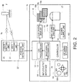
Fig. 2 is a block diagram of the embodiment of the invention. -
Fig. 3A is a schematic view of the embodiment of the invention when viewed from the front.Figs. 3B and 3C are schematic views of the embodiment of the invention when viewed from a side. -
Fig. 4 is a flowchart of the embodiment of the invention. -
Fig. 5 is a flowchart of the embodiment of the invention. -
Figs. 6A to 6D are layouts of image planes of the embodiment of the invention. -
Fig. 7 is a flowchart of the embodiment of the invention. -
Figs. 8A to 8C are layouts of image planes of the embodiment of the invention. -
Fig. 9 is a flowchart of the embodiment of the invention. -
Figs. 10A to 10D are layouts of the image planes of the embodiment of the invention. -
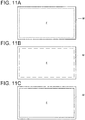
Figs. 11A to 11C are layouts of the image planes of the embodiment of the invention. - Hereinafter, embodiments of the invention will be described with reference to the accompanying drawings. The same reference signs are attached to corresponding components in each drawing and description thereof will not be repeated.
- A
projector 1 as an example of an interactive display apparatus according to the invention illustrated inFigs. 1A and 1B is an apparatus that projects and displays an image to an image plane F. Theprojector 1 projects, to the image plane F, a synthesized image in which an external image formed based on an image signal input from an external device such as a PC or a smart phone and an image of an object corresponding to an operation with respect to a projected surface are synthesized. Theprojector 1 includes afirst housing 1a in which a display unit is accommodated and asecond housing 1b in which a light-emitting unit that radiates light with an infrared wavelength as illustrated in dotted lines inFigs. 1A and 1B in a plane shape is accommodated. When thesecond housing 1b is installed correctly with respect to the image plane F, theprojector 1 can detect an operation with respect to the image plane F. An installation state of thesecond housing 1b with respect to the image plane F is adjusted by rotating twodials second housing 1b. That is, by rotating the twodials second housing 1b is adjusted. - After adjustment of the two
dials finger 99 or the like, the display of the marker M touched by thefinger 99 or the like is stopped. The display of the marker M touched by thefinger 99 or the like is stopped such that the user can recognize that the installation state is appropriate. In a case where the display of the marker M touched by thefinger 99 or the like is not stopped, the user can recognize that the installation state is not appropriate. - As illustrated in
Fig. 2 , theprojector 1 accommodates an input/output interface 14, acontroller 15, anexternal storage 151, anoperation unit 18, apower source unit 19, or the like, in addition to a lightsource drive unit 16, aprojection light source 17, a liquid crystallight valve 10, and a liquidcrystal drive unit 11 as the display unit, in thefirst housing 1a. In addition, theprojector 1 accommodates a light-emittingunit 20, a light-receivingunit 21, and aposition detecting unit 22 in thesecond housing 1b which is installed with respect to the image plane F. The light-emittingunit 20, the light-receivingunit 21, and theposition detecting unit 22 configure the light curtain. In addition, the light-receivingunit 21 and theposition detecting unit 22 configure the position detecting unit. - The
projection light source 17 is configured of a high-pressure mercury vapor lamp, a light-emitting diode (LED), a laser, or the like, and is driven by the lightsource drive unit 16. The input/output interface 14 includes a plurality of types of input/output terminals such as a USB terminal, an Ethernet (registered trademark) terminal, an HDMI terminal, and an RS232c terminal, performs communication with the external device, and inputs various image signals from the external device. Thecontroller 15 executes a control program which is stored in theexternal storage 151 and controls each unit of theprojector 1. In addition, thecontroller 15 includes an imagesignal processing unit 13 and anOSD processing unit 12, executes a drawing process based on the image signals input from the external device and a positional signal input from theposition detecting unit 22, and outputs a projection signal. The imagesignal processing unit 13 outputs image data of an external image layer and image data of an operation input layer to theOSD processing unit 12 as a result of the drawing process based on the image signals input from the external device and the positional signal input from theposition detecting unit 22. TheOSD processing unit 12 synthesizes items of image data of layers and outputs a projection signal corresponding to the liquid crystallight valve 10. The liquidcrystal drive unit 11 converts the projection signal output from theOSD processing unit 12 into an analog signal for driving each pixel of the liquid crystallight valve 10. The liquid crystallight valve 10 includesliquid crystal panels liquid crystal panels projection light source 17 and separated by a dichroic mirror which is not illustrated for each pixel. Theoperation unit 18 includes amenu key 181 for inputting an instruction of projecting an OSD menu, aselection key 182 for selecting an item of the OSD menu, adetermination key 183, and apower switch 184 for switching between ON and OFF of power supply to thepower source unit 19 from an external power source. Thepower source unit 19 supplies power to each unit of theprojector 1. - The light-emitting
unit 20 is a light source which radiates light with an infrared wavelength in a plane shape. The light radiated from the light-emittingunit 20 expands in a fan shape as illustrated in dotted lines inFig. 1A . As illustrated inFigs. 3A to 3C , the light-emittingunit 20 is fixed to an installation surfacef using screws dials support member 24. The installation surface f may be a surface of ascreen 1c on which the image plane F is projected, may be a wall surface on which thescreen 1c is fixed, or may be a bottom surface of thesecond housing 1b which is fixed on thescreen 1c or the wall surface. Thescrews support member 24 fixes an end section of the light-emittingunit 20 on a side opposite to the side, from which the light with the infrared wavelength is radiated, to the installation surface f such that the two corners of the light-emittingunit 20 are elevated from the installation surface f as illustrated inFig. 3B and Fig. 3C by rotation of thescrews dials support member 24 may be configured of an elastic member such as a rubber block. - The light-receiving
unit 21 is an infrared video camera installed to image the entire image plane F, photoelectrically converts the light with the infrared wavelength, and outputs image data according to an image of the light with the infrared wavelength. The light-receivingunit 21 may be accommodated in thesecond housing 1b, in thefirst housing 1a, or in another housing. - The position detecting unit 22 analyzes the image data output from the light-receiving unit 21, thereby detecting a position at which the finger 99 is in contact with the image plane F, and outputs a positional signal representing a coordinate of the position at which the finger 99 is in contact with the image plane F. Light with the infrared wavelength which is radiated from the light-emitting unit 20, then, is reflected from an object such as the finger 99 or a rod which is in contact with the image plane F, and is incident to the light-receiving unit 21 is more intensive than light with the infrared wavelength that is incident to the light-receiving unit 21 from the outside of the image plane F. Therefore, the position detecting unit 22 analyzes the image data output from the light-receiving unit 21, thereby detecting a light-emitting position of the light with the infrared wavelength, that is, a position at which the light with the infrared wavelength is reflected from the finger 99 which is in contact with the image plane F, and outputs the positional signal representing a coordinate of the position at which the finger 99 is in contact with the image plane F. The coordinates in the positional signal represents a position of a pixel of the image data output from the light-receiving unit 21. The positional signal is converted by the
controller 15 into a coordinate representing a position of a pixel of an image which is drawn by thecontroller 15. - Next, an installation method of the light curtain will be described with reference to
Fig. 4 . -
Fig. 4 illustrates a flow of a job of fixing thefirst housing 1a and thescreen 1c to a wall surface, a desk, or the like, fixing thesecond housing 1b with respect to the image plane F of thescreen 1c, and then adjusting the posture of the light-emittingunit 20. According to the present example, thescreen 1c is fixed on the wall surface, the image plane F is set on the center portion of the surface of thescreen 1c, and thesecond housing 1b is fixed to thescreen 1c. In this way, the second housing is fixed with respect to the image plane F. Here, the image plane F may be set on a part of the wall surface without using thescreen 1c and thesecond housing 1b may be fixed on the wall surface with the image plane set on a part of thescreen 1c fixed on the wall surface. - When the
second housing 1b is fixed with respect to the image plane F, a user continuously rotates thedials second housing 1b in a first direction and sets the posture of the light-emittingunit 20 such that a distance between the light radiated from the light-emittingunit 20 and the image plane F (S1) is maximized. - Next, the user rotates the
dials unit 20 and the image plane F to a predetermined distance at two predetermined positions (S2). At this time, for example, pins may be positioned upright at the two predetermined places on the image plane F and an amount of rotating of thedials unit 20. - Next, the user checks whether distances between the image plane F and the plane of light radiated from the light-emitting
unit 20 at other two positions on the image plane F are the predetermined distance (S3). At this time, for example, pins may be positioned upright at the two other predetermined places on the image plane F and the user may check whether a portion of the pin which is spaced from the image plane F by a predetermined distance is illuminated with the light radiated from the light-emittingunit 20. In this way, it is possible to prevent the posture of the light-emittingunit 20 from being adjusted using a distance mistakenly measured between the image plane F and the plane of the reflected light from the image plane F. When the light-emittingunit 20 is correctly installed, the light radiated from the light-emittingunit 20 travels in parallel with the image plane F. - Next, the user executes calibration (S4). Specifically, for example, the
controller 15 of theprojector 1 sequentially displays multiple markers in a predetermined region on the image plane F. The user touches the markers which are sequentially displayed, with a finger. When the image plane F is brought into contact with the finger, theposition detecting unit 22 inputs the positional signal to thecontroller 15. When the positional signal is input from theposition detecting unit 22, thecontroller 15 sets a transformation matrix that determines a correlation between a coordinate of any random pixel of the image data output from the light-receivingunit 21 and a coordinate of any random pixel of an image which is drawn by thecontroller 15 on the basis of the positional signal input from theposition detecting unit 22 and a coordinate at which the marker is drawn by thecontroller 15. - Next, the user finally checks the installation state of the light curtain (S5). Here, the user checks whether an operation position with respect to the image plane F is correctly recognized at a coordinate of the image drawn by the
projector 1. Hereinafter, descriptions will be provided in detail with reference toFig. 5 andFigs. 6A to 6D . - First, the
projector 1 displays guidance illustrated inFig. 6A on the image plane F in accordance with the user's instruction (S11). Specifically, when a predetermined operation of theoperation unit 18 is performed, thecontroller 15 displays guidance for guiding a job which the user has to perform next on the image plane F. The job which the user has to perform next is to touch all of a plurality of round markers M which are displayed on the image plane F by theprojector 1 as illustrated inFig. 6B . - After the
controller 15 displays the guidance illustrated inFig. 6A on the image plane F, thecontroller 15 displays the plurality of round markers M on the circumferential edge section on the image plane F as illustrated inFig. 6B (S12). The markers M are displayed on the circumferential edge section on the image plane F which is predetermined as a target region. That is, thecontroller 15 draws an image such that the round markers M are displayed by reference pixels which are pixels corresponding to the target region and outputs a projection signal to the liquidcrystal drive unit 11. As a result, theliquid crystal panels crystal drive unit 11 and the round markers M are displayed on the image plane F by transmitted light of theliquid crystal panels projection light source 17. - Next, the
controller 15 repeats determination of whether or not thefinger 99 is detected, which comes into contact with the target region on the image plane F on which the markers M are displayed until thefinger 99 is detected on the basis of the positional signal input from the position detecting unit 22 (S13). When thefinger 99 comes into contact with the target region on the image plane F on which the markers M are displayed as illustrated inFig. 6C , the positional signal corresponding to the target region is input to thecontroller 15 from theposition detecting unit 22 as long as the light-emittingunit 20 is correctly installed and ambient light has no influence thereon. As a result, thecontroller 15 detects thefinger 99 that comes into contact with the target region on the image plane F on which the markers M are displayed. - When the
finger 99 that comes into contact with the target region on the image plane F is detected, thecontroller 15 erases a marker M on the target region in which contact of thefinger 99 is detected (S14). That is, thecontroller 15 draws an image such that a drive state of the reference pixel corresponding to the target region in which the contact of thefinger 99 is detected is changed, thereby erasing the marker M. - Next, the
controller 15 determines whether or not the entire markers M are erased (S15). Thecontroller 15 repeats the processes from Step S13 when the entire markers M are not erased, guidance is displayed on the image plane F (S16) when the entire markers M are erased, and an installation state checking process ends. When the display of the marker Me continues as illustrated inFig. 6D although the user touches the entire markers M displayed on the image plane F with a finger, the user can easily recognize that it is a state in which it is not possible to detect the operation with respect to the image plane F in the region in which the marker Me is displayed. In this case, it is necessary that thefirst housing 1a is re-disposed such that the image plane F is decreased in size, or that a tape or the like which has properties of absorbing the light with the infrared wavelength, is stuck on the periphery of the image plane F, such that the ambient light is not detected. - According to the example described above, the user can easily and immediately recognize whether or not the light curtain is correctly installed by checking whether or not it is possible to erase the marker M by touching the markers M displayed on the image plane F with a finger. In addition, the user can easily recognize a position of the target region which has to be checked for whether or not it is possible to detect the contact of the object by the marker M displayed by the
projector 1. Since the target region is set on the circumferential edge section of the image plane F so as to display the markers M, it is possible to check or adjust efficiently the installation state of the light curtain. - A technical range of the invention is not limited to the example described above. Needless to say, the invention can be modified in various ways within a range without departing from the gist of the invention.
- According to the invention, depending on a result of determination of whether or not it is possible to detect the object that comes into contact with the target region on the image plane, the drive state of the reference pixel after determination may be different or, for example, the marker may be displayed by the reference pixel when it is possible to detect the object that comes into contact with the target region on the image plane and the marker may not be displayed by the reference pixel when it is not possible to detect the object that comes into contact with the target region on the image plane. An embodiment in which the marker is displayed by the reference pixel will be described when it is possible to detect the object that comes into contact with the target region on the image plane, with reference to
Fig. 7 andFigs. 8A to 8C . - First, the
controller 15 displays guidance for guiding the job which the user has to perform next on the image plane F, for example, as illustrated inFig. 8A (S21). The job which the user has to perform next is to trace the circumferential edge section of the image plane F set as the target region with a finger. Next, thecontroller 15 repeats the determination of whether or not thefinger 99 which comes into contact with the target region on the image plane F is detected on the basis of the positional signal input from theposition detecting unit 22 until thefinger 99 is detected (S22). At this time, the marker that indicates the target region is not displayed on the image plane; however, the user already recognizes, by the guidance, that the circumferential edge section of the image plane F is the target region. When thefinger 99 which comes into contact with the target region on the image plane F is detected, thecontroller 15 displays the marker M in the target region in which the contact of thefinger 99 is detected as illustrated inFig. 8B (S23). That is, thecontroller 15 draws an image such that the drive state of the reference pixel corresponding to the target region, in which the contact of thefinger 99 is detected, is changed, thereby displaying the marker M. Next, thecontroller 15 determines whether or not the entire markers M are displayed (S15). Thecontroller 15 repeats the processes from Step S13 when the entire markers M are not displayed, the end guidance is displayed on the image plane F when the entire markers M are displayed (S16), and the installation state checking process ends. When there is a region E in which a marker M is not displayed as illustrated inFig. 8C although the user traces round the circumferential edge section of the image plane F with a finger, the user can easily recognize that it is a state in which it is not possible to detect an operation with respect to the image plane F in the region E. - In addition, the markers may be displayed in the target region in advance and the markers may be erased when it is not possible to detect the object that comes into contact with the target region on the image plane. An embodiment, in which the markers are erased when it is not possible to detect the object that comes into contact with the target region on the image plane, will be described with reference to
Fig. 9 andFigs. 10A to 10D . First, thecontroller 15 displays guidance for guiding the job which the user has to perform next, on the image plane F, for example, as illustrated inFig. 10A (S31). The job which the user has to perform next is to trace the circumferential edge section of the image plane F set as the target region with a finger within one minute. Next, thecontroller 15 displays a plurality of round markers M on the circumferential edge section of the image plane F which is the target region as illustrated inFig. 10B (S32). Next, thecontroller 15 sets the timer to one minute and the timer starts (S33). Next, thecontroller 15 determines whether or not thefinger 99 that comes into contact with the target region on the image plane F is detected on the basis of the positional signal input from the position detecting unit 22 (S34). Here, although thecontroller 15 detects thefinger 99 which is in contact with the target region on the image plane F, the marker M in the target region at which thefinger 99 that is in contact is detected is not erased as illustrated inFig. 10C . Thecontroller 15 determines whether or not thefinger 99 which comes into contact with the target region is detected with respect to the entire target region (S35) in a case where thefinger 99 which comes into contact with the target region on the image plane F is detected and thecontroller 15 repeats the processes from the determination in Step S34 in a case where there remains a target region in which thefinger 99 which comes into contact with the target region is not detected. Thecontroller 15 determines whether or not one minute set in the timer is up in a case where thefinger 99 which comes into contact with the target region on the image plane F is not detected in Step S34 (S35) and thecontroller 15 repeats the processes from the determination in Step S34 in a case where the time is not up. Thecontroller 15 erases the marker M displayed in the target region in which thefinger 99 which comes into contact with the target region is not detected (S37) in a case where the time of the timer is up. In this way, according to the embodiment in which the marker M is displayed and erased, the display of the marker continues in a case where it is possible to detect an object and the display of the marker is stopped in a case where it is not possible to detect the object within a fixed time. Therefore, it is not possible for the user to immediately recognize a region in which it is not possible to detect the object. However, when there is a region E in which a marker M is not displayed as illustrated inFig. 10D , although the user traces round the circumferential edge section of the image plane F with a finger within one minute, the user can easily recognize that it is a state in which it is not possible to detect an operation with respect to the image plane F in the region E. - In addition, the marker may be displayed in any shape in the target region on the image plane using the reference pixel, for example, in a dotted line as illustrated in
Fig. 11A , in a dashed line as illustrated inFig. 11B , in a combination of the dashed line and the dotted line, or in a continuous line as illustrated inFig. 11C . The marker with such a line shape is displayed and, thereby, it is possible to easily recognize whether or not it is possible to detect the contact of the object in the target region which extends in a line shape. In addition, one or more target regions may be set in any region of the image plane and, for example, the center region of the image plane which represents a point by one reference pixel may be the target region. - In addition, the light-receiving unit and the position detecting unit of the light curtain may not be accommodated in the same housing as the light-emitting unit. For example, the position detecting unit may be accommodated in the same housing with the display unit or the light-receiving unit and the position detecting unit may be accommodated in the same housing with the display unit. In addition, the wavelength of the light radiated from the light-emitting unit of the light curtain may not be the infrared wavelength. For example, the light with an ultraviolet wavelength may be radiated from the light-emitting unit.
- In addition, for example, in order to project an image, the light may be modulated using one liquid crystal panel, the light may be modulated using a reflective liquid crystal panel, or the light may be modulated using a digital mirror device (DMD). In addition, for example, a convex mirror may be used or a mirror may not be used in order to expand and project a projection image. In addition, for example, the invention may be applied to an interactive display apparatus that includes a large-sized flat panel display and the light curtain.
Claims (9)
- A light curtain installation method for adjusting or checking an installation state of a light curtain for detecting an operation with respect to an image plane of a display apparatus, the method comprising:determining whether or not it is possible to detect an object that comes into contact with a target region on the image plane which corresponds to a reference pixel which is a pixel at a predetermined position; andsetting a drive state of the reference pixel such that the drive state of the reference pixel is different depending on a result of the determining.
- The light curtain installation method according to claim 1,
wherein the drive state of the reference pixel is changed in the setting in a case where it is possible to detect the object, and
wherein the drive state of the reference pixel is not changed in the setting in a case where it is not possible to detect the object. - The light curtain installation method according to claim 1,
wherein a marker is displayed in the target region on the image plane by the reference pixel in the determining,
wherein the display of the marker is stopped in the setting in a case where it is possible to detect the object, and
wherein the display of the marker continues in the setting in a case where it is not possible to detect the object. - The light curtain installation method according to claim 1,
wherein the marker is displayed in the target region on the image plane by the reference pixel in the setting in a case where it is possible to detect the object, and
wherein the marker is not displayed in the setting in a case where it is not possible to detect the object. - The light curtain installation method according to claim 1,
wherein a marker is displayed in the target region on the image plane by the reference pixel in the determining,
wherein the display of the marker continues in the setting in a case where it is possible to detect the object, and
wherein the display of the marker is stopped in the setting in a case where it is not possible to detect the object. - The light curtain installation method according to claim 1,
wherein the target region is a circumferential edge section of the image plane. - The light curtain installation method according to claim 3,
wherein the marker is formed of a dotted line, a dashed line, or a combination thereof. - The light curtain installation method according to claim 3,
wherein the marker is formed of a continuous line. - An interactive display apparatus comprising:a display unit that has pixels arranged in a matrix shape and displays an image on an image plane by driving the pixels;a light-emitting unit that is installed with respect to the image plane and radiates light in a plane shape;a position detecting unit that receives and photoelectrically converts direct or reflected light of the light radiated from the light-emitting unit and outputs a positional signal in response to the direct or reflected light; anda control unit that performs determination of whether or not it is possible to detect an object that comes into contact with a target region on the image plane which corresponds to a reference pixel which is a pixel at a predetermined position, based on the positional signal, and sets a drive state of the reference pixel such that the drive state of the reference pixel is different depending on a result of the determining.
Applications Claiming Priority (2)
| Application Number | Priority Date | Filing Date | Title |
|---|---|---|---|
| JP2014068253A JP6229572B2 (en) | 2014-03-28 | 2014-03-28 | Light curtain installation method and bidirectional display device |
| PCT/JP2015/001780 WO2015146190A1 (en) | 2014-03-28 | 2015-03-27 | Light curtain installation method and bidirectional display device |
Publications (2)
| Publication Number | Publication Date |
|---|---|
| EP3125085A1 true EP3125085A1 (en) | 2017-02-01 |
| EP3125085A4 EP3125085A4 (en) | 2017-12-06 |
Family
ID=54194734
Family Applications (1)
| Application Number | Title | Priority Date | Filing Date |
|---|---|---|---|
| EP15768889.6A Withdrawn EP3125085A4 (en) | 2014-03-28 | 2015-03-27 | Light curtain installation method and bidirectional display device |
Country Status (7)
| Country | Link |
|---|---|
| US (1) | US10013117B2 (en) |
| EP (1) | EP3125085A4 (en) |
| JP (1) | JP6229572B2 (en) |
| KR (1) | KR101955257B1 (en) |
| CN (1) | CN106133666B (en) |
| TW (1) | TWI635350B (en) |
| WO (1) | WO2015146190A1 (en) |
Families Citing this family (4)
| Publication number | Priority date | Publication date | Assignee | Title |
|---|---|---|---|---|
| TWI608393B (en) | 2016-05-27 | 2017-12-11 | 光峰科技股份有限公司 | Projection system and optical screen generating device thereof |
| JP7099173B2 (en) * | 2018-08-24 | 2022-07-12 | セイコーエプソン株式会社 | Light emitting device and image display system |
| CN109855563B (en) * | 2019-02-21 | 2024-06-18 | 深圳市凯中精密技术股份有限公司 | Detection method and detection device |
| CN116681216A (en) * | 2023-07-31 | 2023-09-01 | 山东莱恩光电科技股份有限公司 | Stamping instrument safety monitoring method based on safety light curtain historical data |
Family Cites Families (21)
| Publication number | Priority date | Publication date | Assignee | Title |
|---|---|---|---|---|
| JP2003276399A (en) | 2002-03-25 | 2003-09-30 | Matsushita Electric Ind Co Ltd | Position detecting method and device, and electronic blackboard device |
| JP2004101317A (en) | 2002-09-09 | 2004-04-02 | Matsushita Electric Ind Co Ltd | Position detecting method, position detecting device and electronic blackboard |
| JP3947873B2 (en) | 2003-10-10 | 2007-07-25 | Necディスプレイソリューションズ株式会社 | Projector and projector accessory |
| JP3950837B2 (en) | 2003-10-21 | 2007-08-01 | Necディスプレイソリューションズ株式会社 | Projector, electronic blackboard system using projector, and indication position acquisition method |
| JP4166229B2 (en) * | 2005-03-14 | 2008-10-15 | 株式会社日立製作所 | Display device with touch panel |
| JP4708278B2 (en) | 2006-05-12 | 2011-06-22 | 株式会社アシスト | Touch panel system and operation method thereof |
| JP5277703B2 (en) * | 2008-04-21 | 2013-08-28 | 株式会社リコー | Electronics |
| JP4690473B2 (en) * | 2009-03-06 | 2011-06-01 | シャープ株式会社 | Image analysis apparatus, image analysis method, imaging apparatus, image analysis program, and recording medium |
| TWI423096B (en) | 2010-04-01 | 2014-01-11 | Compal Communication Inc | Projecting system with touch controllable projecting picture |
| JP2012027769A (en) * | 2010-07-26 | 2012-02-09 | Seiko Epson Corp | Interactive white board device, image display device and calibration method |
| US9760123B2 (en) * | 2010-08-06 | 2017-09-12 | Dynavox Systems Llc | Speech generation device with a projected display and optical inputs |
| JP5655450B2 (en) * | 2010-09-13 | 2015-01-21 | セイコーエプソン株式会社 | Optical detection apparatus and information processing system |
| TWI501130B (en) * | 2010-10-18 | 2015-09-21 | Ind Tech Res Inst | Virtual touch control system |
| JP5673191B2 (en) | 2011-02-21 | 2015-02-18 | セイコーエプソン株式会社 | Interactive system, position information conversion method, and projector |
| JP5804596B2 (en) * | 2011-11-18 | 2015-11-04 | インターナショナル・ビジネス・マシーンズ・コーポレーションInternational Business Machines Corporation | Display device, input method, and program |
| WO2013104061A1 (en) * | 2012-01-11 | 2013-07-18 | Smart Technologies Ulc | Calibration of an interactive light curtain |
| TWI460508B (en) * | 2012-04-25 | 2014-11-11 | Au Optronics Corp | Lighting device and back light module therewith |
| CN102914937B (en) * | 2012-09-28 | 2015-03-25 | 苏州佳世达光电有限公司 | Projection system with touch control function |
| CN103091964B (en) * | 2013-01-10 | 2015-03-25 | 苏州佳世达光电有限公司 | Adjusting auxiliary tool and projection system |
| JP6037900B2 (en) * | 2013-03-11 | 2016-12-07 | 日立マクセル株式会社 | Operation detection device and operation detection method |
| JP2015158558A (en) * | 2014-02-24 | 2015-09-03 | セイコーエプソン株式会社 | projector |
-
2014
- 2014-03-28 JP JP2014068253A patent/JP6229572B2/en active Active
-
2015
- 2015-03-25 TW TW104109578A patent/TWI635350B/en active
- 2015-03-27 WO PCT/JP2015/001780 patent/WO2015146190A1/en not_active Ceased
- 2015-03-27 CN CN201580015308.6A patent/CN106133666B/en active Active
- 2015-03-27 EP EP15768889.6A patent/EP3125085A4/en not_active Withdrawn
- 2015-03-27 US US15/126,805 patent/US10013117B2/en active Active
- 2015-03-27 KR KR1020167030049A patent/KR101955257B1/en active Active
Also Published As
| Publication number | Publication date |
|---|---|
| WO2015146190A1 (en) | 2015-10-01 |
| TW201546536A (en) | 2015-12-16 |
| JP6229572B2 (en) | 2017-11-15 |
| TWI635350B (en) | 2018-09-11 |
| CN106133666B (en) | 2019-05-07 |
| CN106133666A (en) | 2016-11-16 |
| US10013117B2 (en) | 2018-07-03 |
| EP3125085A4 (en) | 2017-12-06 |
| US20170090678A1 (en) | 2017-03-30 |
| KR20160139014A (en) | 2016-12-06 |
| KR101955257B1 (en) | 2019-05-30 |
| JP2015191455A (en) | 2015-11-02 |
Similar Documents
| Publication | Publication Date | Title |
|---|---|---|
| US8806074B2 (en) | Display device, projector, display system, and method of switching device | |
| CN103870233B (en) | Display device and its control method | |
| US20150237319A1 (en) | Projection system and projection method thereof | |
| CN103186293A (en) | Display device, display system, and data supply method for display device | |
| US10013117B2 (en) | Light curtain installation method and interactive display apparatus | |
| CN103365549A (en) | Input device, display system and input method | |
| US10303307B2 (en) | Display system, information processing device, projector, and information processing method | |
| CN104978079B (en) | Bi-directional display method and bi-directional display device | |
| US8917291B2 (en) | Projector and control method | |
| KR20180071846A (en) | Display apparatus and the controlling method thereof | |
| CN106164828B (en) | Bidirectional display method and bidirectional display device | |
| JP6565133B2 (en) | Bidirectional display method and bidirectional display device | |
| KR101909105B1 (en) | Bidirectional display method and bidirectional display device | |
| JP6255810B2 (en) | Display device and control method of display device | |
| CN112055185A (en) | Operation method and display device | |
| US11353971B2 (en) | Method for controlling display device, and display device | |
| JP5803427B2 (en) | Display device, display device control method, and program | |
| KR20070008056A (en) | Pointing device of LCC TV | |
| KR20170011476A (en) | Electric board for mutual connection with terminals |
Legal Events
| Date | Code | Title | Description |
|---|---|---|---|
| PUAI | Public reference made under article 153(3) epc to a published international application that has entered the european phase |
Free format text: ORIGINAL CODE: 0009012 |
|
| 17P | Request for examination filed |
Effective date: 20161028 |
|
| AK | Designated contracting states |
Kind code of ref document: A1 Designated state(s): AL AT BE BG CH CY CZ DE DK EE ES FI FR GB GR HR HU IE IS IT LI LT LU LV MC MK MT NL NO PL PT RO RS SE SI SK SM TR |
|
| AX | Request for extension of the european patent |
Extension state: BA ME |
|
| DAV | Request for validation of the european patent (deleted) | ||
| DAX | Request for extension of the european patent (deleted) | ||
| A4 | Supplementary search report drawn up and despatched |
Effective date: 20171107 |
|
| RIC1 | Information provided on ipc code assigned before grant |
Ipc: G06F 3/042 20060101ALI20171101BHEP Ipc: G06F 3/041 20060101ALI20171101BHEP Ipc: H04N 9/31 20060101AFI20171101BHEP Ipc: G03B 21/14 20060101ALI20171101BHEP |
|
| STAA | Information on the status of an ep patent application or granted ep patent |
Free format text: STATUS: THE APPLICATION HAS BEEN WITHDRAWN |
|
| 18W | Application withdrawn |
Effective date: 20190321 |