JP4166229B2 - Display device with touch panel - Google Patents
Display device with touch panel Download PDFInfo
- Publication number
- JP4166229B2 JP4166229B2 JP2005071622A JP2005071622A JP4166229B2 JP 4166229 B2 JP4166229 B2 JP 4166229B2 JP 2005071622 A JP2005071622 A JP 2005071622A JP 2005071622 A JP2005071622 A JP 2005071622A JP 4166229 B2 JP4166229 B2 JP 4166229B2
- Authority
- JP
- Japan
- Prior art keywords
- pressure
- touch
- icon
- screen
- operation member
- Prior art date
- Legal status (The legal status is an assumption and is not a legal conclusion. Google has not performed a legal analysis and makes no representation as to the accuracy of the status listed.)
- Expired - Lifetime
Links
Images


Description
本発明は、据置型や携帯型などの端末装置に用いられるタッチパネルを備えた
表示装置に関する。
The present invention relates to a display device provided with a touch panel used in a stationary or portable terminal device.
近年、各種業界では、端末装置が広く使用されるようになってきている。例えば、銀行などでATM(Automatic Tellers Machine:自動預入支払機)が、駅などでは券売機や地図案内機が夫々設置され、銀行や駅などの業務の一部を端末装置で賄うことができるようにしている。また、ファーストフード店などの店舗においても、商品の注文処理に端末装置を用いるようにする場合もあり(例えば、特許文献1参照)、さらに、インターネットなどの通信ネットワークを利用してコンテンツの配信を受ける端末装置やウェブ閲覧(ブラウズ)用の端末装置なども実現あるいは提案されている。 In recent years, terminal devices have been widely used in various industries. For example, ATMs (Automatic Tellers Machines) are installed at banks, and ticket machines and map guides are installed at stations, etc., so that a part of business such as banks and stations can be covered by terminal devices. I have to. Also, in stores such as fast food restaurants, terminal devices may be used for merchandise order processing (see, for example, Patent Document 1), and content distribution is performed using a communication network such as the Internet. Receiving terminal devices and web browsing (browsing) terminal devices are also realized or proposed.
ところで、このような端末装置では、表示装置が設けられており、その表示画面に表示されるメッセージなどの情報を見ながらキーボードなどの入力手段を操作することにより、上記のような各種の作業ができるようにしているが、表示画面に入力手段としての機能を持たせ、その表示画面に表示されるメッセージやメニューなどにしたがって画面操作を行なうことにより、各種の作業を実行することができるようにしたタッチパネルを備えた表示装置が用いられるようになってきている。 By the way, in such a terminal device, a display device is provided, and various operations as described above can be performed by operating input means such as a keyboard while viewing information such as messages displayed on the display screen. The display screen has a function as an input means, and various operations can be performed by operating the screen according to messages and menus displayed on the display screen. Display devices having a touch panel have been used.
このようなタッチパネルを備えた表示装置によると、その表示画面に直接指先を触れて操作を行なうものであるから、操作がし易く、操作の間違いが少ない、という優れた操作性を実現することができるし、また、キーボードなどの操作部も、操作ボタンの数を少なくすることができるので、端末装置自体を小型化でき、設置面積も狭くできて、店内や構内などでの設置場所の自由度が高まるといったようなメリットも得られることになる。
しかし、従来のタッチパネルを備えた表示装置では、その表示画面に操作ボタン(タッチボタン)などのタッチ操作部材からなる入力手段の画像を表示することにより、その入力手段を顧客やユーザの視覚で認識させ、この認識のもとに、この入力手段の画像の操作したいと思われる個所をタッチすることで所定の処理を実行する。 However, in a display device equipped with a conventional touch panel, an image of an input unit made of a touch operation member such as an operation button (touch button) is displayed on the display screen, so that the input unit is recognized visually by a customer or a user. Then, based on this recognition, a predetermined process is executed by touching a place where the image of the input means is desired to be operated.
パソコンでは、マウスによるドラッグ・アンド・ドロップ機能が付加されている。マウスでは、カーソルを自由に移動させることができるとともに、クリックボタンを操作することができるので、クリックボタンを押しながらアイコンを移動させたり、あるいは、アイコンにカーソルを合わせて、クリックボタンをダブルクリックすることで予め設定されたアイコンの機能を実行させることができる。 A personal computer has a drag-and-drop function with a mouse. With the mouse, the cursor can be moved freely and the click button can be operated, so the icon can be moved while holding the click button, or the cursor is moved to the icon and the click button is double-clicked. Thus, a preset icon function can be executed.
しかし、従来のタッチパネルでは、1回のタッチを検知して各種処理を実行しているために、1つの処理しか実行することができない。例えば、ATMなどで採用されているタッチパネルを備えた表示装置では、表示画面のタッチ操作部材にタッチすると、その時点でこのタッチ操作部材に関する機能が実行されるため、タッチ操作によってドラッグ・アンド・ドロップを行なわせることができない。タッチパネルを備えた小型の情報機器では、ドラッグ・アンド・ドロップを可能にしたものがあるが、これらは、アイコンに予め設定された機能を実行するためには、予め設定されたタイミングで2回タッチしなければならない。マウスの操作では、表示画面に表示されるカーソルを見ながら間接的に操作するため、視認性や操作性に左程問題を生じない。しかし、表示画面に表示されたタッチ操作部材を直接操作するタッチパネルにおいては、一度タッチした箇所を同じタイミングでタッチしなければならないために、誤操作や操作性に課題がある。特に、不特定の操作者が操作するATMや自動機などの公共機器においては、操作者全部に同じタイミングで2回タッチさせることには課題が残る。 However, since the conventional touch panel detects one touch and executes various processes, only one process can be executed. For example, in a display device equipped with a touch panel adopted by ATM or the like, when a touch operation member on the display screen is touched, a function related to the touch operation member is executed at that time, so that drag and drop is performed by the touch operation. Can not be done. Some small information devices equipped with a touch panel can be dragged and dropped. However, in order to execute a function set in advance on an icon, these are touched twice at a preset timing. Must. In the mouse operation, since the operation is performed indirectly while looking at the cursor displayed on the display screen, there is no problem as far as the left in viewability and operability. However, in the touch panel that directly operates the touch operation member displayed on the display screen, the touched part has to be touched at the same timing, so that there are problems in erroneous operation and operability. In particular, in public equipment such as an ATM or an automatic machine operated by an unspecified operator, there is a problem in making all the operators touch twice at the same timing.
本発明の目的は、かかる問題を解消し、操作ボタンなどのタッチ操作部材をユーザが所望とする位置に任意に移動させることができ、かつタッチ操作部材に予め設定された機能を実行できるタッチパネルを備えた表示装置を提供することにある。 An object of the present invention is to solve such a problem, it can be moved to any touch operation member such as an operation button to the position desired by the user, and a touch panel capable of executing a predetermined function on the touch operation member It is to provide a display device provided.
上記目的を達成するために、本発明は、表示パネルの表示面に表示されるタッチ操作部材のタッチ状態の2段階検出を可能とし、第1のタッチ状態でこのタッチ操作部材の表示画面上での移動を可能とし、第2のタッチ状態で該タッチ操作部材に関する機能の実行を可能とするものである。 In order to achieve the above object, the present invention enables two-stage detection of the touch state of a touch operation member displayed on the display surface of the display panel, and on the display screen of the touch operation member in the first touch state. Movement of the touch operation member is enabled in the second touch state.
即ち、本発明に係る代表的な手段は、タッチ操作部材をタッチ操作する際の指示手段によって押圧される押圧力Pを検知する検知手段と、設定圧力P1及びこの設定圧力P1より大きい設定圧力P2が予め設定され、該検知手段で検知した押圧力Pが設定圧力P1≦押圧力P<設定圧力P2であるとき、該指示手段によって押圧された該タッチ操作部材に関する第1の処理を行ない、該押圧力Pが設定圧力P2≦押圧力Pであるとき、該指示手段によって押圧された該タッチ操作部材に関する第2の処理を行なう制御部とを有し、該第1の処理は、該指示手段が移動すると、該タッチ操作部材を該指示手段に付いて移動させるドラッグ処理であり、該第2の処理は該タッチ操作部材の移動に関する処理であって、該タッチ操作部材への該指示手段による押圧力Pが、押圧力P<設定圧力P1から設定圧力P1≦押圧力P<設定圧力P2を経て、設定圧力P2≦押圧力Pに変化したとき、該タッチ操作部材の移動開始を許可する該第2の処理を行ない、次いで、該タッチ操作部材への該指示手段による押圧力Pが緩んで設定圧力P2≦押圧力Pから設定圧力P1≦押圧力P<設定圧力P2に変化したとき、設定圧力P1≦押圧力P<設定圧力P2である限り、該タッチ操作部材のドラッグ処理を該第1の処理として行ない、次いで、該タッチ操作部材への該指示手段による押圧力Pがさらに緩んで設定圧力P1≦押圧力P<設定圧力P2から押圧力P<設定圧力P1に変化したとき、該タッチ操作部材の移動先をそのときの位置に決定する処理を行ない、タッチ操作部材をタッチ操作する際の該押圧力Pの押圧力P<設定圧力P1から設定圧力P2≦押圧力Pへの変化、または設定圧力P2≦押圧力Pから押圧力P<設定圧力P1への変化が所定時間内に行なわれた場合には、該ドラッグ処理または該移動開始を許可する処理を行なうことなく、該タッチ操作部材に予め割り当てられた機能を実行することで、上記目的を達成する。 That is, representative means according to the present invention include detection means for detecting the pressing force P pressed by the instruction means when the touch operation member is touch-operated, the set pressure P1, and the set pressure P2 larger than the set pressure P1. Is set in advance, and when the pressing force P detected by the detecting means is set pressure P1 ≦ pressing pressure P <set pressure P2, the first processing related to the touch operation member pressed by the indicating means is performed, A control unit that performs a second process relating to the touch operation member pressed by the instruction unit when the pressing force P is a set pressure P2 ≦ the pressing force P. The first process includes the instruction unit. Is a drag process for moving the touch operation member along the instruction means when the movement of the touch operation member, and the second process is a process related to the movement of the touch operation member, the instruction to the touch operation member Allow the pressing force P by stages, through the pressing force P <Configuration set pressure from the pressure P1 P1 ≦ pressing force P <set pressure P2, when changing the set pressure P2 ≦ pressing force P, the movement start of the touch operation member The second process is performed, and then the pressing force P applied to the touch operation member by the instruction means is loosened to change from the set pressure P2 ≦ the pressed pressure P to the set pressure P1 ≦ the pressed pressure P <the set pressure P2. As long as the setting pressure P1 ≦ the pressing force P <the setting pressure P2, the drag operation of the touch operation member is performed as the first processing, and then the pressing force P by the instruction means on the touch operation member is further relaxed. in when changed from the set pressure P1 ≦ pressing force P <set pressure P2 in the pressing force P <set pressure P1, it performs a process of determining the destination of the touch operation member to a position at that time, touch operation on the touch operation member The change of the pressing force P at the time of pressing P <the set pressure P1 to the set pressure P2 ≦ the pressed pressure P or the change from the set pressure P2 ≦ the pressed pressure P to the pressed pressure P <the set pressure P1 within a predetermined time. In the case where the touch operation member is performed , the above-mentioned object is achieved by executing a function assigned in advance to the touch operation member without performing the drag process or the process of permitting the start of movement.
本発明によると、指先などによる押圧力Pを検知する検知手段と、この押圧力PがP1≦P<P2であるときに第1の処理を、P1≦P<P2からP2≦Pに変化したときに第2の処理を行なう制御部とを設け、該第1の処理は、指先が移動すると、タッチ操作部材を指先に附いて移動させる処理とし、第2の処理は該タッチ操作部材に関する機能を実行させる処理とするものであるから、ドラッグ・アンド・ドロップなどのタッチ操作部材を移動させる機能を指先でのタッチ操作で行なうことが可能となり、表示画面でのタッチ操作部材の配置の変更などをタッチ操作でもって容易にかつ確実に行なうことができるし、複数の操作ボタンの操作が関連されて1つの機能が実行されるような場合には、複数のタッチ操作部材のタッチ操作の経緯を確認する必要がなくなって、操作が簡単でかつ誤操作を軽減することができる。 According to the present invention, the detecting means for detecting the pressing force P by the fingertip or the like, and the first process when the pressing force P is P1 ≦ P <P2, is changed from P1 ≦ P <P2 to P2 ≦ P. A control unit that performs a second process, and the first process is a process of moving the touch operation member on the fingertip when the fingertip moves, and the second process is a function related to the touch operation member. Because it is a process to execute touch, it is possible to perform a function to move the touch operation member such as drag and drop by touch operation with the fingertip, change the arrangement of the touch operation member on the display screen, etc. Can be easily and reliably performed by a touch operation, and when a plurality of operation buttons are related and one function is executed, the touch operation of a plurality of touch operation members is performed. It unnecessary to confirm, can be operated to reduce the simple and erroneous operation.
以下、本発明の実施形態を図面を用いて説明する。 Hereinafter, embodiments of the present invention will be described with reference to the drawings.
図1は本発明によるタッチパネルを備えた表示装置の一実施形態を示す図であって、同図(a)は外観斜視図、同図(b)は側面図、同図(c)は断面図であり、1は筐体、1aは開口、2は表示画面、3は取付部、4はスタンド、5は回転軸、6はピン穴、7はピン、8は表示パネル、8aは表示面、9はタッチパネル、10は支持部材である。 FIG. 1 is a view showing an embodiment of a display device provided with a touch panel according to the present invention. FIG. 1 (a) is an external perspective view, FIG. 1 (b) is a side view, and FIG. 1 is a housing, 1a is an opening, 2 is a display screen, 3 is a mounting portion, 4 is a stand, 5 is a rotating shaft, 6 is a pin hole, 7 is a pin, 8 is a display panel, 8a is a display surface, 9 is a touch panel and 10 is a support member.
同図において、箱型の筐体1の前面に矩形状の開口1aが形成されており、この開口1aに表示画面2が設けられている。この表示画面2に、図示しないが、操作ボタンやメッセージなどのタッチ操作で割り当てられた機能を実行する部材,エリア(以下、タッチ操作部材という)が表示され、かかるタッチ操作部材を指先やペン先、あるいはペン型の入力デバイスなどの指示手段でタッチ操作することにより、この実施形態である表示装置を利用した装置(例えば、パソコンや携帯端末,ATM,券売機など)を動作させることができる。
In the figure, a
この筐体1の開口1aとは反対側の背面側には、取付部3が一体に設けられており、この取付部3が回転軸5を介してスタンド4に取り付けられている。この取付部3は、従って、筐体1は、スタンド4に対して、この回転軸5を中心に回動可能であり、筐体1をこのように回動させることにより、表示画面2の向きを変えることができる。
An
表示画面2の向きを連続的に変えることができるようにしてもよいが、ここでは、段階的に変化できるようにしている。このために、図1(b)に示すように、取付部3の側面部に、回転軸5を中心として複数のピン穴6が設けられており、これらピン穴6の配列線上の一点に対向して、このピン穴6に嵌り込むピン7がスタンド4に押し込み可能に設けられている。筐体1を回転軸5を中心に回動させ、表示画面2を所定の向きにすると、ピン7がこれに近いピン穴6に嵌め込むことができ、表示画面2はほぼこの所定の向きで安定化する。
Although the orientation of the
このように、ピン穴6とピン7とは、表示画面の向き(角度)を調整手段を構成しており、ピン穴6の個数分だけ、表示画面2の向きを変えることができる。
Thus, the
この筐体1内では、図1(c)に示すように、表示手段としての表示パネル8が支持部材10によって支持されて取り付けられており、筐体1の開口1a側に、表示画面2として、この表示パネル8の映像を表示する表示面8aが、その全体を覆うようにして設けられたタッチパネル9とともに、配置されている。
In the
図2は図1における筐体1内の表示手段の具体例を概略的に示す図であって、同図(a)は表示パネル8として液晶パネルやブラウン管,プラズマ表示パネルなどの場合であり、同図(b)は液晶プロジェクタなどのプロジェクタの場合である。そして、これらの図面において、11は支持部材、12は映出装置、13はミラー、14はスクリーン、15は支持部材であり、図1に対応する部分には同一符号を付けて重複する説明を省略する。
FIG. 2 is a diagram schematically showing a specific example of the display means in the
図2(a)において、筐体1内では、上記のように、表示パネル8が支持部材10によって支持されており、タッチパネル9が支持部材11によって表示パネル8に支持されている。
2A, in the
タッチパネル9は、表示面8a全体を覆う透明な膜を設けた構成をなしており、ユーザが指先などでタッチしたことを検知して(タッチ検知)、そのタッチ位置を検出する(位置検出)ものであるが、さらに、この具体例では、このタッチしたときの圧力を検出する(圧力検出の)機能も備えている。この圧力検出の機能を持たせる方法としては、次の表1に示すように、3つの方法がある。

表1において、例1は、タッチパネル9にタッチ検知とこれによるタッチ位置の位置検出とタッチ位置での圧力検出との機能を持たせるものであり、支持部材10,11には、その本来の表示パネル8の支持、タッチパネル9の支持の機能のみを持たせるものである。例2は、表示パネル8を支持する支持部材10に、圧力センサを設けて、圧力検出の機能も持たせるものであり、タッチパネル9及び支持部材11は本来の機能のみを持つ。例3は、タッチパネル9を支持する支持部材11に、圧力センサを設けて、圧力検出の機能も持たせるものであり、タッチパネル9及び支持部材10は本来の機能のみを持つ。
In Table 1, Example 1 is an example in which the
図2(b)に示す具体例では、筐体1内に、映像を発生する液晶パネルやブラウン管などからなる映出装置12とミラー13とスクリーン14とからなるプロジェクタが設けられており、このスクリーン14の外側にこれと一体にタッチパネル9が設けられている。これらスクリーン14とタッチパネル9とは、支持部材15でもって、筐体1の開口1aに支持されている。
In the specific example shown in FIG. 2 (b), a
映出装置12には、図示しない投写レンズが設けられており、映出装置12からの映像はミラー13を介してスクリーン14に投写されるが、投写レンズにより、スクリーン14に投写される映像は拡大されている。なお、映出装置12が直接スクリーン14に対向して設けられる場合には、ミラー13を省くことができる。
The
この具体例も、タッチパネル9にタッチしたときの圧力を検出する(圧力検出)の機能も備えている。この圧力検出の機能を持たせる方法としては、次の表2に示すように、2つの方法がある。
表2において、例4は、タッチパネル9にタッチ検知とこれによるタッチ位置の位置検出とタッチ位置での圧力検出との機能を持たせるものであり、支持部材15には、その本来の表示パネル8を支持する機能のみを持たせるものである。例5は、支持部材15に、圧力センサを設けて、圧力検出の機能も持たせるものであり、タッチパネル9は本来の機能のみを持つ。
In Table 2, Example 4 is an example in which the
なお、上記表1,2において、タッチ検知とはタッチパネル9に指先16がタッチしたことを検知する従来のタッチパネルの機能をいう。
In Tables 1 and 2, the touch detection refers to a function of a conventional touch panel that detects that the
但し、上記いずれの例においても、タッチパネル9で指先16のタッチ位置が検出されたとき、指先16がタッチパネル9にタッチされた(即ち、P≧P1になった)と判定するようにしてもよい。
However, in any of the above examples, when the touch position of the
図3はタッチパネル9に対する指先の状態を示す図であり、同図(a)は指先16がタッチパネル9に触れていない状態、同図(b),(c)はタッチパネル9に指先16が触れた状態を夫々示している。そして、同図(b)は指先16がタッチパネル9に軽く触った状態であり、同図(c)は指先16がタッチパネル9に、それを強く押し込むようにして、触った状態である。
FIG. 3 is a diagram showing the state of the fingertip with respect to the
また、図4は上記の圧力センサが検出する圧力に対する図3に示す指先16の状態の判定(この判定は、後述する制御部によってなされる)を示す図であり、横軸にタッチパネル9にかかる圧力(タッチパネル9を押す力:以下、押圧力という)Pを示し、縦軸に押圧力Pに対する判定結果を示す。
FIG. 4 is a diagram showing determination of the state of the
図4において、予め弱い圧力P1の値と強い圧力P2の値とが設定されており、タッチパネル9への押圧力PがP<P1のとき、タッチパネル9への押圧力無し(反応無し)とし、P1≦P<P2のとき、タッチパネル9にタッチされたと判定し(上記表1,2での「タッチ検知」)、そのタッチ位置の検出が行なわれる。また、押圧力PがP2≦Pのときには、タッチパネル9には、これが押し込まれるような強い押圧力が掛かったことになり、タッチパネル9が押し込まれたと判定する(上記表1,2での「圧力検知」)。
In FIG. 4, when the value of the weak pressure P1 and the value of the strong pressure P2 are set in advance, and the pressing force P to the
図3(a)に示す状態は、図4でのP<P1の状態を示すものであって、この状態では、タッチパネル9にタッチされていないと判定される。また、図3(b)は指先16がタッチパネル9にタッチした状態を示すものであるが、このとき、0≦P<P1であれば、図4から、タッチパネル9にタッチされていないと判定するし、P1≦P<P2であれば、タッチパネル9にタッチされただけで押し込まれてはいないと判定される。これによって誤動作を軽減することができる。図3(c)は指先16でタッチパネル9を押し込むようにタッチした状態を示すものであり、図4において、P2≦Pの状態である。このときには、タッチパネル9が押し込まれると判定される。
The state shown in FIG. 3A shows the state of P <P1 in FIG. 4, and in this state, it is determined that the
以上のように、この実施形態では、タッチパネル9の2段階検知を可能とするものである。この2段階検知によれば、キーボードの操作性に近い操作感覚を使用者に与えることができる。例えば、使用者は、軽いタッチ(P1≦P<P2)でキー位置を確認して、このキーを強く押し込む(P2≦P)ようなキーボードの操作感覚を得ることができる。従って、この2段階検知によれば、今までのタッチパネルでは得られなかった確かな操作感覚を使用者に与えることができる。そして、この2段階検知を採用したこの実施形態によれば、表示画面をタッチすることで特定の機能を実行させることができるとともに、後述するようなドラッグ・アンド・ドロップと同様な操作をタッチ操作で実現することができる。しかも、この実施形態によれば、タッチした指を離すことなく、タッチの強さで特定の「機能の実行」と「ドラッグ・アンド・ドロップ」とを区別することができる。従って、従来例のようなタッチのタイミングで同様な機能を実行するものと比べて誤操作が起こりにくく、快適な操作感覚を提供することができる。
As described above, in this embodiment, two-step detection of the
ここでは、指先を例にとって説明するが、指先のほか、ペンなどの棒状の部材やペン型の入力デバイスなどでも、本発明のタッチパネルを操作することができる。 Here, a fingertip will be described as an example, but the touch panel of the present invention can be operated with a finger-like member, a pen-shaped member such as a pen, or a pen-type input device.
なお、上記の圧力P1(>0)は、例えば、振動などによってタッチパネル9に不当な圧力が掛かった場合、タッチパネル9がタッチされたという誤判定を防止するために設定されたものである。
The pressure P1 (> 0) is set to prevent an erroneous determination that the
図5はこの実施形態での回路構成の一具体例の要部を示すブロック図であって、同図(a)は上記表1,2での例1,4に対するものであり、同図(b)は上記表1,2での例2,3,5に対応するものである。そして、これらの図面において、17は制御部、18はスピーカ、19は記憶部であり、図1,図2に対応する部分には同一符号を付けて重複する説明を省略する。
FIG. 5 is a block diagram showing an essential part of a specific example of the circuit configuration in this embodiment. FIG. 5 (a) is for Examples 1 and 4 in Tables 1 and 2, and FIG. b) corresponds to Examples 2, 3, and 5 in Tables 1 and 2 above. In these drawings,
図5(a)に示す回路構成では、タッチパネル9がタッチセンサと圧力センサとを備えており、この圧力センサの検出圧力(押圧力)Pが制御部17に供給される。制御部17は、この検出圧力Pを基に、図4で説明した判定を行ない、その判定結果に応じて、記憶部19に記憶されているデータを基に、後述するように、表示パネル8や映出装置12を制御し、また、スピーカ18で所定の音声再生を行なわせる。
In the circuit configuration shown in FIG. 5A, the
図5(b)に示す回路構成の場合でも、支持部材10,11,15に設けられた圧力センサの検出圧力Pに応じて、制御部17が同様の機能制御を行なう。
Even in the case of the circuit configuration shown in FIG. 5B, the
次に、圧力Pに対する制御部17の動作について説明する。なお、以下では、図4に示すように、この圧力Pが0≦P<P1であるときの制御部17による処理をA、P1≦P<P2であるときの制御部17による処理をB、P2≦Pであるときの制御部17による処理をCとする。これらの処理については後述するが、処理Aは、当然のことながら、タッチパネル9へのタッチ操作もなされていないときの処理である。
Next, operation | movement of the
ここで、図6により、図5(a),(b)における記憶部19について説明する。
Here, the
表示部8,12での表示画面2では、アイコンや操作ボタンなどのタッチ操作部材が表示されるが、制御部17が指先16(図3)のタッチ位置を検出したとき、このタッチ位置がタッチ操作部材のエリア内であるか否かを判定するためのデータやタッチ操作部材毎の機能を決めるデータなどが記憶部19に記憶されている。
Touch operation members such as icons and operation buttons are displayed on the
図6(a)はタッチ位置がタッチ操作部材のエリア内であるか否かを判定するためのデータを表わすデータベースの一具体例を示すものであって、タッチパネル9上の位置を座標(xi,yj)で表わし(但し、i,j=1,2,……)、各タッチ操作部材をオブジェクト(object)1,2,3,……として表わしている。この具体例によると、タッチパネル9上の位置(xi,y1),(xi,y2),……には、オブジェクト3が配置されていることを示している。なお、オブジェクトが複数の座標位置に跨がるのは、オブジェクトが、例えば、アイコンのように、ある面積のエリアを有するからである。この場合、このデータベースでのオブジェクトに関するデータは、例えば、このオブジェクトに固有に割り当てられたID(識別符号)である。
FIG. 6A shows a specific example of a database representing data for determining whether or not the touch position is within the area of the touch operation member. The position on the
また、図6(a)に示すデータベースは、タッチパネル9上の位置とオブジェクトの関係を示すものであるが、さらに、記憶部19には、図示しないが、各オブジェクト毎に、それに関する機能を表わすデータベース(以下、機能データベースという)が格納されている。
Further, the database shown in FIG. 6A shows the relationship between the position on the
制御部17は、上記のようにしてタッチパネル9での指先16のタッチ位置を検出すると、このタッチ位置を図6(a)に示すデータベースと比較し、このタッチ位置がオブジェクトのエリア内にあるか否か、また、ある場合には、いずれのオブジェクトのエリア内かを判定し、例えば、オブジェクト3のエリア内にあるとすると、現在このオブジェクト3がタッチされている状態と判定し、機能データベースの中からこのオブジェクト3の検出される圧力Pに応じた機能データを読み取り、表示部8,12(図5)をこの機能データに応じて制御する。
When the
また、図6(b)はタッチパネル9でのタッチ操作部材(オブジェクト)のエリアとタッチパネル9の位置(xi,yj)とを関連付けたデータベースであり、タッチ操作部材のエリアをエリア(are)1,2,3,……で表わしたものである。これ以外については、図6(a)に示したデータベースと同様である。
FIG. 6B is a database in which the area of the touch operation member (object) on the
以下、制御部17のかかる機能制御による本発明の情報処理方法の実施形態について説明するが、かかる実施形態は、表示画面2に表示されるアイコンなどのオブジェクトをドラッグ・アンド・ドロップする機能を持たせたものである。
Hereinafter, an embodiment of the information processing method of the present invention by the function control of the
図7は制御部17のかかる機能制御による情報処理方法の第1の実施形態を示すフローチャートである。図8はこの実施形態を実行中に表示画面2に表示される画面の一具体例を示すものであって、20はオブジェクト(ここでは、アイコンとするが、これに限るものではない)である。図9はこの実施形態での図8に対する動作を行なわせるための圧力Pの変化を示す図である。図10はこの実施形態を実行中に表示画面2に表示される画面の他の具体例を示すものであって、図8に対応する部分には同一符号をつけている。図11はこの具体例での図10に対する動作を行なわせるための圧力Pの変化を示す図である。
FIG. 7 is a flowchart showing a first embodiment of the information processing method by the function control of the
図7において、図示しない電源がオンとされると、制御部17は処理Aを行なって装置を動作開始状態にする(ステップ100)。そして、まず、電源をオフするなどして動作の終了条件が設定されたか否か判定し(ステップ101)、設定されていない場合には、図5での圧力センサからその検出圧力Pを取り込み、P≧P1かどうか判定する(ステップ102)。図3(a)に示すような状態にあって、P<P1のときには、タッチパネル9へのタッチ操作もなされていないとして、ステップ100に戻り、タッチ操作がなされるまで、ステップ100〜102の一連の動作が繰り返され、その間処理Aが実行される。このときの表示画面2(図1)に表示される画面を図8,図10での画面V1とする。これら画面V1では、説明を簡単にするために、1つのアイコン20が表示されているものとする。
In FIG. 7, when a power supply (not shown) is turned on, the
いま、タッチ操作として、一瞬にして図3(c)に示すようなタッチパネル9へのタッチ操作がなされると、図9に示すように、タッチパネル9へのタッチ操作によってP≧P2まで圧力が変化するが、制御部17は、まず、P≧P1と判定し(ステップ102)、次いで、P≧P2と判定する(ステップ103)動作を瞬間的に行なう。以下、かかる操作を押し込み操作という。
Now, as a touch operation, when a touch operation on the
そして、制御部17は、タッチ位置を検出して、図6で説明したように、このタッチ位置が機能するアイコンのエリア内にあるか否か判定し(ステップ104)、図8に示す画面V1内のアイコン20以外のエリアがタッチされているときには、ステップ100に戻り、タッチ状態に変化がない限り、ステップ100〜104の一連の動作を繰り返す。しかし、タッチ位置が図8に示す画面V1内のアイコン20のエリア内である場合には(ステップ104)、タッチされたアイコン20の色が変わったり、振動したりした図8の画面V2に移るが、この場合、P≧P2であることから、この画面V2も一瞬であって、アイコン20の色をさらに変えたり、サイズを変えたり、振動をさらに激しくするなどした図8の画面V3となり、これとともに、このアイコン20によって決められる機能が実行される(ステップ105)。そして、指先16をタッチパネル9から離すなどしてP<P2の状態となると、制御部17はアイコン20の機能を終了させ(ステップ107)、ステップ100に戻ってステップ100〜102の動作を繰り返し、図8の画面V4が表示されて待機する。
Then, the
この第1の実施形態によれば、タッチされたアイコン20の色が変わったり、振動したりするので、使用者はタッチされた位置を明確に把握することができる。そして、このタッチされたアイコン20を強く押し込む操作で、さらにアイコン20を変化させるので、指の動作に連動して視覚的に押し込み操作を自覚させることができる。これにより、キーボードのようなタッチ感覚と押し込み操作の2段階操作を実現して、使用者に確かな操作感覚を提供することができる。
According to the first embodiment, since the color of the touched
以上はP≧P2の場合であったが、P2>P≧P1の場合には(ステップ102,103)、制御部17(図5)はタッチセンサの出力から指先16のタッチ位置を検知し、これと記憶部19(図5)のデータとを比較することにより、このタッチ位置がアイコン20のエリア内かどうか判定する。このエリア内である場合には、このアイコン20が移動可能であるかどうかを判定し、移動可能である場合には、制御部17はタッチ位置が移動可能なアイコン20のエリア内にあると判定し、アイコン20が移動可能であるとともに、移動を開始できることを示すように表示した図10に示す画面V2を表示画面2に表示させる(ステップ108)。かかる移動可能であること、移動を開始できることを示す表示方法としては、例えば、アイコン20の表示色を変化させたり、振動させたりするなどの方法がある。また、サイズを変えるようにしてもよいし、これらを組み合わせてもよい。
The above is the case of P ≧ P2, but when P2> P ≧ P1 (
なお、そして、図示しないが、かかる状態で指先16をタッチパネル9から離してP<P1の状態にすると、もとのステップ100の状態に戻る。
Although not shown, when the
かかるP1≦P<P2の状態でアイコン20のエリア内にある指先16(即ち、タッチ位置)を移動させると(ステップ109)、位置(x0,y0)のアイコン20がこの移動する指先16に引かれて移動するドラッグが行なわれる(ステップ110)。このとき、この移動を表わす図10の画面V5が表示画面2に表示される。図11に示すように、タッチが行なわれている限り、即ち、P≧P1である限り(ステップ111)、このアイコン20のドラッグが継続する。
When the fingertip 16 (that is, the touch position) within the area of the
その後、所定の位置で指先16をタッチパネル9から離し、図11に示すように、P<P1の状態とすると(ステップ111)、そのときの位置(x1,y1)にアイコン20の位置が決定し、ドラッグが終了する(ステップ112)。そして、アイコン20がこの決定した位置にもとの表示状態で位置付けられた図10に示す画面V6が表示画面2に表示された状態となり、ステップ100に戻る。
After that, when the
このようにして、この第1の実施形態では、簡単なタッチ操作により、画面に表示されるアイコンなどの移動可能なオプジェクトを所定の位置に移すことができる。また、勿論、P≧P2とすることにより、このオブジェクトの機能も実行させることができる。 Thus, in the first embodiment, movable objects such as icons displayed on the screen can be moved to a predetermined position by a simple touch operation. Of course, by setting P ≧ P2, the function of this object can also be executed.
また、この第1の実施形態では、一旦ドラッグ動作に移行してオブジェクトの移動が開始されると、指を離さない限りドラッグ動作を継続するようにしている。従って、ドラッグ動作の途中でオブジェクトをP≧P2としても、ドラッグ動作中のオブジェクトに割り当てられた機能を実行することがないので、移動中にオブジェクトの機能を実行させてしまう誤操作がなく、使用者は安心してドラッグ動作を行なうことができる。 In the first embodiment, once the transition to the drag operation is started and the movement of the object is started, the drag operation is continued unless the finger is released. Accordingly, even if the object is set to P ≧ P2 in the middle of the drag operation, the function assigned to the object being dragged is not executed, so there is no erroneous operation that causes the object function to be executed during movement, and the user Can perform drag operations with peace of mind.
従って、この第1の実施形態によれば、指の押圧力を2段階に検知することで、オブジェクトの機能の実行とドラッグ操作を容易に、かつ間違えることなく、区別して操作することができる。 Therefore, according to the first embodiment, by detecting the finger pressing force in two stages, it is possible to easily perform the function execution of the object and the drag operation without making a mistake.
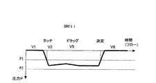
図12は図5における制御部17の機能制御による情報処理方法の第2の実施形態を示すフローチャートであって、この第2の実施形態も、上記の第1の実施形態と同様、表示画面2に表示されたアイコンなどのオブジェクトをドラッグ・アンド・ドロップする機能を持たせるものである。
FIG. 12 is a flowchart showing a second embodiment of the information processing method based on the function control of the
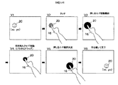
また、図13はかかる第2の実施形態を実行中に表示画面2に表示される画面を示すものであって、図12に対応する部分には同一符号を付けている。
FIG. 13 shows a screen displayed on the
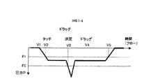
さらに、図14はこの具体例での動作を行なわせるための押圧力Pの変化を示す図であり、時間軸に沿って図13に対応した画面番号V1〜V5を記載している。 Further, FIG. 14 is a diagram showing changes in the pressing force P for performing the operation in this specific example, and screen numbers V1 to V5 corresponding to FIG. 13 are described along the time axis.
図12において、ステップ200〜202,211は図7でのステップ100〜102,113と同様であり、指先16がタッチパネル9にタッチしていない状態であって、表示画面2には、図13に示す画面V1が表示されている。この画面V1では、上記第1の実施形態と同様に、アイコン20がこの表示画面2上の位置(x1,y1)に表示されているものとする。
12,
かかる画面V1の表示状態で指先16がアイコン20の表示位置にタッチして、図14に示すように、P1≦Pの押圧力Pが圧力センサで検知されたものとすると(ステップ202)、制御部17(図5)はタッチセンサの出力から指先16のタッチ位置を検知し、これと記憶部19(図5)のデータとを比較することにより、このタッチ位置がアイコン20のエリア内かどうか判定する(ステップ203)。このエリア内である場合には、制御部17はタッチ位置が移動可能なアイコン20のエリア内にあると判定し、図13に示すように、アイコン20が移動可能であることを示すように表示した画面V2を表示画面2に表示させる(ステップ204)。かかる移動可能であることを示す表示方法としては、例えば、アイコン20の表示色を変化させたり、振動させたりするなどの方法がある。
When the
次いで、上記のようにタッチした状態でこのアイコン20を押し込むようにすることにより(かかるタッチ位置を、以下、押し込み位置という)、図14に示すように、P2≦Pの押圧力Pが圧力センサで検知されたものとすると(ステップ205)、制御部17(図5)はタッチセンサの出力から指先16の押し込み位置を検知し、これと記憶部19(図5)のデータとを比較することにより、この押し込み位置がアイコン20のエリア内かどうか判定する。このエリア内である場合には、制御部17は、図13に示すように、アイコン20が移動開始可能であることを示すように表示した画面V3を表示画面2に表示させる(ステップ206)。かかる移動開始可能であることを示す表示方法としては、例えば、アイコン20のサイズを大きくしたり、表示色を変化させたり、振動させたりするなどの方法がある。
Next, by pressing the
そして、かかる画面V3の表示状態で指先16によるアイコン20の押し込みを解除して指先16の押圧力Pを弱め、指先16でタッチパネル9にタッチした状態で(このとき、図14に示すように、P1≦P<P2)指先16を移動させると、これについてアイコン20を移動(ドラッグ)させることができ、図13に示すように、アイコン20が指先16について移動する画面V4が表示画面2に表示される(ステップ207)。このようなときのアイコン20の表示方法としては、例えば、表示色をさらに変化させたり、サイズを変化させたりするなどの方法がある。ここでは、サイズが元に戻り、色がさらに変えられたものとする。
Then, in the display state of the screen V3, the pressing of the
このようにして、P1≦P<P2である限り(ステップ208,209)、指先16でアイコン20をドラッグさせることができるが、指先16をタッチパネル9から離してP<P1の状態とすることにより(ステップ208)、そのときの位置(x2,y2)にアイコン20の位置が決定され(ドロップ)、ドラッグ・アンド・ドロップが終了する(ステップ210)。そして、アイコン20がこの位置(x2,y2)にもとの表示状態で位置付けられた図13に示す画面V5が表示画面2に表示された状態となり、ステップ200に戻る。
In this way, as long as P1 ≦ P <P2 (
このようにして、この第2の実施形態でも、簡単なタッチ操作により、画面に表示されるアイコンなどの移動可能なオプジェクトを所定の位置に移すことができる。特に、この第2の実施形態では、アイコン20にタッチしてP1≦P<P2の状態としても、アイコン20を移動させることができない。P1≦P<P2の状態から指先16を押し込むようにしてP≧P2の状態とすることで、初めて、アイコン20をドラッグの状態とすることができる。従って、図14に示すように、画面V2と画面V3の間の時間があっても、ドラッグの状態とすることができない。このため、アイコン20をタッチしても不用意にアイコン20がずれてしまうことがないので、安心して操作することができる。特に、この第2の実施形態では、まず、目的のアイコン20にタッチして内容を確認(アイコン20の変化)し、それからドラッグ操作を決定することができるので、弱視の操作者などに有効である。
Thus, also in the second embodiment, movable objects such as icons displayed on the screen can be moved to a predetermined position by a simple touch operation. In particular, in the second embodiment, the
なお、この第2の実施形態では、説明を簡単にするために、ドラッグ・アンド・ドロップの操作を中心に説明している。勿論、アイコン20に設定された機能を実行させるための押し込み操作と併用させてもよい。この場合、例えば、ステップ202において、P≧P1であるときには、P≧P2か否かの判定も行ない、P≧P2であるときには、図7でのステップ104〜107と同様の機能実行の動作を行なうようにしてもよい。
In the second embodiment, the drag and drop operation is mainly described in order to simplify the description. Of course, you may use together with pushing operation for performing the function set to the
この場合、上記ステップ205との混同を避けるために、ステップ200〜202の待機中に、P<P1の状態からP≧P2となるアイコン20の押し込み操作が短時間に行なわれた場合には、アイコン20のドラッグ動作を許可とは判定せず、このアイコン20の機能を実行するようにするとよい。または、P≧P2となるアイコン20の押し込み操作の後、短時間のうちに指を離したとき、即ち、P≧P1となったときにアイコン20の機能を実行することとしてもよい。
In this case, in order to avoid confusion with the
あるいは、表示画面の特定の領域では実行動作を受け付け、他の領域ではドラッグ操作を受け付けるように、各オブジェクトに設定してもよい。 Or you may set to each object so that execution operation may be received in the specific area | region of a display screen, and drag operation may be received in another area | region.
また、図12において、ステップ208の後に、ドラッグ動作中のアイコン20に対して、指先16を押し込むような操作(P≧P2)がなされることでも、そのときの位置(x2,y2)をアイコン20の位置決定としてもよい(ステップ209)。
In FIG. 12, after
図15は図5における制御部17の機能制御による情報処理方法の第3の実施形態を示すフローチャートであって、この第3の実施形態も、表示画面2に表示されたアイコンなどのオブジェクトをドラッグ・アンド・ドロップする機能を持たせるものである。
FIG. 15 is a flowchart showing a third embodiment of the information processing method by the function control of the
また、図16はかかる第3の実施形態を実行中に表示画面2に表示される画面を示すものであって、図12に対応する部分には同一符号を付けている。
FIG. 16 shows a screen displayed on the
さらに、図17はこの第3の実施形態での動作を行なわせるための押圧力Pの変化を示す図であり、時間軸に沿って図16に対応した画面番号V1〜V6を記載している。 Further, FIG. 17 is a diagram showing changes in the pressing force P for performing the operation in the third embodiment, and screen numbers V1 to V6 corresponding to FIG. 16 are described along the time axis. .
図15において、ステップ300〜302,313は図7でのステップ100〜102,113と同様であり、指先16がタッチパネル9にタッチしていない状態であって、表示画面2には、図16に示す画面V1が表示されている。この画面V1では、アイコン20がこの表示画面2上の位置(x0,y0)に表示されているものとする。
15,
かかる画面V1の表示状態で指先16がアイコン20の表示位置にタッチし、このタッチにより、図17に示すように、P≧P1の圧力Pが検知されたものとすると(ステップ302)、制御部17(図5)は、上記具体例と同様にして、このタッチ位置がアイコン20のエリア内かどうか判定する。このエリア内である場合には、制御部17はタッチ位置が移動可能なアイコン20のエリア内にあると判定し(ステップ303)、図16に示すように、アイコン20が移動可能であることを示すように表示した画面V2を表示画面2に表示させる(ステップ304)。かかる移動可能であることを示す表示方法としては、例えば、アイコン20の表示色を変化させたり、振動させたりするなどの方法がある。
When the
そして、かかる表示状態で指先16でアイコン20を押し込むようにし、図17に示すように、圧力PがP≧P2にすると(ステップ305)、図16に示すように、アイコン20が移動を開始させることができることを表わすような表示状態の画面V3が表示画面2に表示される(ステップ306)。このようなときのアイコン20の表示方法としては、例えば、表示色をさらに変化させたり、サイズを変化させたりするなどの方法がある。ここでは、サイズと色が変えられたものとして示している。
Then, when the
なお、図示しないが、かかる状態(ステップ306)で指先16をタッチパネル9から離してP<P1の状態にすると、アイコン20に対する機能の選択がなされることになり、この選択された機能が決定してこの機能が実行される。
Although not shown, if the
しかし、画面V3で指先16の押圧力を弱めて図17に示すP1≦P<P2の状態にし、アイコン20のエリア内にある指先16を移動させると、この移動する指先16に引かれてアイコン20が移動するドラッグが行なわれる。図16の画面V4は、このときに表示画面2に表示される画面を示すものであって、アイコン20は、例えば、サイズが画面V3のときよりも小さく変化している(ステップ307)。この場合、この移動の途中で指先16をタッチパネル9から離し、P<P1の状態とすると、ドラッグが中断し、アイコン20はもとの位置(x0,y0)に自動的に戻り(ステップ312)、図16に示すもとの画面V1が表示された状態となる(ステップ300)。
However, if the pressing force of the
また、上記ドラッグを継続し(ステップ307〜309)、その後、アイコン20を所定の位置(x3,y3)に持ってきて、指先16でアイコン20を押し込むようにして、図17に示すように、P≧P2とすると(ステップ309)、図16に示すように、アイコン20が、例えば、画面V3での状態と同じ状態で表わされた画面V5が表示され、アイコン20の位置がこの所定の位置(x3,y3)に確定する(ステップ310)。そして、指先16をタッチパネル9から離して、図17に示すように、P<P1の状態にすると、アイコン20が位置(x3,y3)にもとの表示状態で位置付けられた画面V6が表示画面2に表示された状態となり(ステップ311)、ステップ300に戻る。
Further, the dragging is continued (
このようにして、この第3の実施形態でも、簡単なタッチ操作により、画面に表示されるアイコンなどの移動可能なオプジェクトを所定の位置に移すことができる。 Thus, also in the third embodiment, movable objects such as icons displayed on the screen can be moved to a predetermined position by a simple touch operation.
この第3の実施形態では、意図せずに(アイコン20をタッチして誤って移動する)アイコン20を移動させることがないので、複数の人で同じ端末を共有する場合に適している。また、この第3の実施形態では、移動を確定する場合においても、押し込み操作を行なうようにしているので、移動先が不用意に決定される誤操作を軽減できる。特に、移動先がその位置によって意味や価値が異なる場合(例えば、「送信トレー」や「ごみ箱」など)は、操作者が意識して押し込み操作を行なうことで移動先が決定されるので、誤操作を軽減できる。
In the third embodiment, the
なお、この第3の実施形態においても、先の各実施形態と同様な操作でアイコン20に設定された機能を実行させるための押し込み操作と併用させてもよい。
In the third embodiment as well, a push-in operation for executing a function set in the
また、表示画面2に複数の機能の種類が異なるアイコンが表示されるとき、これらアイコンのドラッグ・アンド・ドロップの操作方法として、アイコンの機能の種類毎に、上記第1〜第3の方法のいずれかを各アイコンに割り当てるようにし、機能の種類毎にドラッグ・アンド・ドロップの操作方法を異なるようにすることができる。勿論、特定の機能を持つアイコンに対しては、ドラッグ・アンド・ドロップができないようにしてもよい。
In addition, when icons having different types of functions are displayed on the
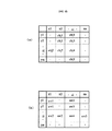
図18は図5における制御部17の機能制御による情報処理方法の第4の実施形態を示すフローチャートであって、この第4の実施形態は表示画面2に品目を表わすアイコンなどのオブジェクトをタッチ操作部材としてドラッグ・アンド・ドロップ可能とし、所望品目の購入などの処理機能を持たせる、所謂ドラック・アンド・機能選択というべきものである。この第4の具体例は、デジタルコンテンツの配信端末の機能を持つものとしている。
FIG. 18 is a flowchart showing a fourth embodiment of the information processing method by function control of the
また、図19はかかる第4の実施形態を実行中に表示画面2に表示される画面を示すものであって、21はオブジェクト表示領域、22は機能設定領域、23,23’はオブジェクト(ここでは、品目を表わすアイコンとするが、これに限るものではない)、24は案内、25は「購入する」ボタン、26は「やめる」ボタンである。
FIG. 19 shows a screen displayed on the
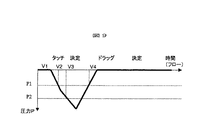
さらに、図20はこの第4の実施形態での動作を行なわせるための圧力Pの変化を示す図であり、時間軸に沿って図19に対応した画面番号V1〜V5を記載している。 Further, FIG. 20 is a diagram showing a change in the pressure P for performing the operation in the fourth embodiment, and screen numbers V1 to V5 corresponding to FIG. 19 are described along the time axis.
図18において、ステップ400〜402,411は図7でのステップ100〜102,113と同様であり、指先16がタッチパネル9にタッチしていない状態であって、表示画面2には、図19に示す画面V1が表示されている。この画面V1では、機能設定領域22で設定されている項目の機能の実行が可能な各種品目を示すアイコン23が表示されるアイコン(オブジェクト)表示領域21と、かかる品目を、例えば、音楽のコンテンツとした場合、その「購入」や「試聴」,「書評を見る」などの機能を実行可能とする項目のメニューが表わされる機能設定領域22とが設けられている。但し、これらは品目の一例であって、本発明はこれに限るものではなく、また、品目の種類によって機能メニューも異なるものである。
18,
かかる画面V1の表示状態で、指先16が希望する品目のアイコン23の表示位置にタッチし、このタッチにより、図20に示すように、P2>P≧P1の圧力Pが検知されたものとすると(ステップ402)、制御部17(図5)は、先の具体例と同様にして、このタッチ位置がアイコン23のエリア内にあるかどうか判定する。このエリア内にある場合には、制御部17はタッチ位置が移動可能なアイコン23のエリア内にあると判定し(ステップ403)、表示画面2に図19に示す画面V2をアイコン23が移動開始可能であるように表示させる。かかる移動可能であることを示す表示方法としては、例えば、アイコン23の表示色を変化させたり、振動させたりするなどの方法がある。
In the display state of the screen V1, the
そして、図20に示すように、P1≦P<P2でのかかる表示状態で指先16を移動させると、アイコン23からこれと同じ内容の分身のアイコン23’が生じ、これがこの移動する指先16に引かれて移動するドラッグが行なわれる(ステップ404)。図19の画面V3はこのときに表示画面2に表示される画面を示すものであって、アイコン23’は指先16にくっついて移動する。
Then, as shown in FIG. 20, when the
かかる移動の途中で指先16をタッチパネル9から離し、P<P1の状態とすると(ステップ405)、ドラッグが中断し、アイコン23’は消滅して(もしくはアイコン表示領域21でのアイコン23の位置に自動的に戻ってこのアイコン23と重なり)(ステップ410)、図19に示すもとの画面V1が表示された状態となる(ステップ400)。
If the
また、図20に示すように、P1≦P<P2のタッチ状態で指先16を移動させ、上記ドラッグを継続し(ステップ404〜406)、その後、アイコン23’を機能設定領域22内の所望の機能メニュー、例えば、この品目を購入したい場合には、機能メニュー「購入する」に合わせると(ステップ407)、表示画面2に表示される画面が図19に示す画面V4となり、次に、指先16をこのアイコン23’から離さずに押し込むようにして、図20に示すように、P≧P2とすると(ステップ407)、図19に示すように、このアイコン23’による品目のより詳細な案内24を表わす画面V5が表示画面2に表示される(ステップ408)。これによって、誤って機能メニューを選択しても、案内24を表示させることで、誤操作を軽減することができる。
Further, as shown in FIG. 20, the
この品目を購入する場合には、この案内24での「購入する」ボタン25をタッチ操作することにより、ダウンロードなどによってこの品目を購入することが可能となり、「やめる」ボタン26をタッチ操作すると、購入をやめることができる。このような処理が終わると(ステップ409)、ステップ400に戻って図19に示すもとの画面V1が表示された状態となる。
When purchasing this item, it is possible to purchase this item by touching the “Purchase” button 25 in this
このようにして、この第4の実施形態では、コンテンツの配信などを要求する場合のように、複数の操作ボタンの操作が関連されて1つの機能が実行されるような場合には、複数のタッチ操作部材のタッチ操作の経緯を確認する必要がなくなって、簡単なタッチ操作で実行させることができ、さらに、誤って所望の機能以外の領域に確定することなく、確実にコンテンツの配信などを受けるようにすることができる。 In this manner, in the fourth embodiment, when a function is executed in association with operations of a plurality of operation buttons, such as when content distribution is requested, a plurality of operations are performed. It is no longer necessary to check the background of the touch operation of the touch operation member, it can be executed with a simple touch operation, and content delivery etc. can be performed reliably without accidentally determining an area other than the desired function. You can make it receive.
特に、この第4の実施形態では、上記のアイコン(タッチ操作部材)は、押圧力PがP1≦押圧力P<P2でタッチされたとき、指(指示手段)の移動に伴ってその表示位置が移動するドラッグ処理(第1の処理)が可能であり、かつ、ドラッグ処理でこのアイコンが移動された先の領域(所望の機能メニュー)との組み合わせにより前記アイコンに予め割り当てられた処理(第2の処理)を実行させることができる。 In particular, in the fourth embodiment, when the pressing force P is touched with P1 ≦ pressing force P <P2, the icon (touch operation member) has its display position as the finger (instruction means) moves. A drag process (first process) in which the icon is moved is possible, and a process (first process) pre-assigned to the icon by combination with the previous area (desired function menu) to which the icon has been moved by the drag process. 2 processing) can be executed.
なお、この第4の実施形態において、オブジェクト表示領域21内で、オブジェクトが押し込まれた場合には、このオブジェクト23に設定された機能を実行してもよい。例えば、この第4の実施の形態では、「試聴」できるようにしてもよい。
In the fourth embodiment, when an object is pushed in the
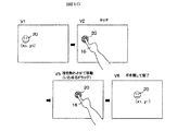
図21は図5における制御部17の機能制御による情報処理方法の第5の実施形態を示すフローチャートであって、この第5の実施形態はポップアップメニューの選択機能を持たせたものである。
FIG. 21 is a flowchart showing a fifth embodiment of the information processing method based on the function control of the
また、図22はかかる第5の実施形態を実行中に表示画面2に表示される画面を示すものであり、27はメニューオブジェクト、28はポップアップメニュ、29は選択枠(カーソル)である。
FIG. 22 shows a screen displayed on the
さらに、図23はこの第5の実施形態での動作を行なわせるための押圧力Pの変化を示す図であり、時間軸に沿って図22に対応した画面番号V1〜V5を記載している。 Further, FIG. 23 is a diagram showing changes in the pressing force P for performing the operation in the fifth embodiment, and screen numbers V1 to V5 corresponding to FIG. 22 are shown along the time axis. .
図21において、ステップ500〜502,511は図7でのステップ100〜102,113と同様であり、指先16がタッチパネル9にタッチしていない状態であって、表示画面2には、図22に示す画面V1が表示されている。この画面V1では、メニューオブジェクト27が表示されている。
In FIG. 21,
かかる表示状態でメニューオブジェクトを変更する場合には、指先16で現在表示されているメニューオブジェクト27にタッチする。制御部17は、これにより、図23に示すように、P2>P≧P1の圧力Pが検知すると(ステップ502)、先の具体例と同様にして、このタッチ位置がメニューオブジェクト27のエリア内にあるかどうか判定する。このエリア内にある場合には、制御部17はタッチ位置が移動可能なメニューオブジェクト27のエリア内にあると判定し(ステップ503)、表示画面2に図22に示す画面V2が表示される。この画面V2では、これまで表示されていたメニューオブジェクト27aとともに他のメニューオブジェクトが配列されてなるポップアップメニュー28が表示され、その中の1つのメニューオブジェクト、この場合、これまで表示されていて指先16でタッチされたメニューオブジェクト27aが、そのときの位置で選択枠29によって選択された状態で表示される。
When the menu object is changed in such a display state, the menu object 27 currently displayed with the
このようなタッチ状態で、ポップアップメニュー28内をメニューオブジェクトの配列方向に指先16を移動させると、選択枠29もこの指先16とともに移動(ドラッグ)する。図22に示す画面V3はこのときの表示画面2で表示される画面である(ステップ504)。P1≦P<P2を保って指先16を移動させている限り、ステップ505〜507の動作が繰り返され、選択枠29が指先16に附いてドラッグする。この操作中にタッチパネル9から指先を離し、P<P1の状態とすると(ステップ505)、かかる動作が中断し、メニューオブジェクト27はもとの位置に戻って(ステップ510)、図22に示すもとの画面V1が表示された状態となる(ステップ500)。
When the
また、図23に示すように、P1≦P<P2のタッチ状態で指先16を移動させることにより、選択枠29がポップアップメニュー28の所望とするメニューオブジェクト27dの位置(選択肢領域内)に達し(ステップ507)、指先16をこの選択枠29から離さずに押し込み操作を行なって、図23に示すように、P≧P2とすると、この所望とするメニューオブジェクト27dの選択が実行される(ステップ508)。図22に示す画面V4はこのとき表示画面2に表示される画面を示すものであって、例えば、選択枠29の表示色が変化して選択が実行されたことを示す。そして、図22の画面V5となり、選択されたメニューオブジェクト27dが、メニューオブジェクト27aに代わって、このもとのメニューオブジェクト27aと同じ位置に表示されることになり(ステップ509)、ステップ500に戻って次の操作を待つことになる。
Further, as shown in FIG. 23, by moving the
このようにして、この第5の実施形態では、簡単なタッチ操作により、ポップアップメニューの選択を行なうことができる。特に、ポップアップメニューでは、望所の機能を選択するためにポップアップメニューを開いて選択肢(機能)を閲覧する操作も多い。この第5の実施形態では、このような閲覧操作を、「指で触れ」,「確認し」,「指を離す」という至って簡単な操作で実行することができるとともに、いざ選択肢を実行(選択)しようとした場合には、強く押し込む操作で実行(選択)するので、不用意に指が離れて操作者自身が意図しない、気が付かずに他の選択肢が実行(選択)されてしまうような誤操作を軽減することができる。 Thus, in the fifth embodiment, the pop-up menu can be selected by a simple touch operation. In particular, in the pop-up menu, there are many operations for browsing the choices (functions) by opening the pop-up menu in order to select a desired function. In the fifth embodiment, such a browsing operation can be executed by simple operations such as “touch with a finger”, “confirm”, and “release the finger”, and execute an option (selection). ) If you try to do it, it will be executed (selected) by pushing it in too hard, so the operator will inadvertently leave the finger unintentionally, or other options will be executed (selected) without realizing it Can be reduced.
なお、この第5の実施形態では、1つのポップアップメニューで説明したが、複数のポップアップメニューを表示しても、同様な効果を得ることができる。 Although the fifth embodiment has been described with one pop-up menu, the same effect can be obtained even when a plurality of pop-up menus are displayed.
1 筐体
1a 開口
2 表示画面
3 取付部
4 スタンド
5 回転軸
6 ピン穴
7 ピン
8 表示パネル
8a 表示面
9 タッチパネル
10,11 支持部材
12 映出装置
13 ミラー
14 スクリーン
15 支持部材
16 指先
17 制御部
18 スピーカ
19 記憶部
20 アイコン
21 オブジェクト表示領域
22 機能設定領域
23,23’ オブジェクト(アイコン)
24 案内
25 「購入する」ボタン
26 「やめる」ボタン
27a,27d メニューオブジェクト
28 メニューオブジェクト欄
29 選択枠
DESCRIPTION OF
24 Information 25 “Purchase”
Claims (1)
該タッチ操作部材をタッチ操作する際の指示手段によって押圧される押圧力Pを検知する検知手段と、
設定圧力P1及び、この設定圧力P1より大きい設定圧力P2が予め設定され、該検知手段で検知した押圧力Pが設定圧力P1≦押圧力P<設定圧力P2であるとき、該指示手段によって押圧された該タッチ操作部材に関する第1の処理を行ない、該押圧力Pが設定圧力P2≦押圧力Pであるとき、該指示手段によって押圧された該タッチ操作部材に関する第2の処理を行なう制御部と
を有し、
該第1の処理は、該指示手段が移動すると、該タッチ操作部材を該指示手段に付いて移動させるドラッグ処理であり、該第2の処理は該タッチ操作部材の移動に関する処理であって、
該タッチ操作部材への該指示手段による押圧力Pが、押圧力P<設定圧力P1から設定圧力P1≦押圧力P<設定圧力P2を経て、設定圧力P2≦押圧力Pに変化したとき、該タッチ操作部材の移動開始を許可する該第2の処理を行ない、
次いで、該タッチ操作部材への該指示手段による押圧力Pが緩んで設定圧力P2≦押圧力Pから設定圧力P1≦押圧力P<設定圧力P2に変化したとき、設定圧力P1≦押圧力P<設定圧力P2である限り、該タッチ操作部材のドラッグ処理を該第1の処理として行ない、
次いで、該タッチ操作部材への該指示手段による押圧力Pがさらに緩んで設定圧力P1≦押圧力P<設定圧力P2から押圧力P<設定圧力P1に変化したとき、該タッチ操作部材の移動先をそのときの位置に決定する処理を行ない、
該タッチ操作部材をタッチ操作する際の該押圧力Pの押圧力P<設定圧力P1から設定圧力P2≦押圧力Pへの変化、または設定圧力P2≦押圧力Pから押圧力P<設定圧力P1への変化が所定時間内に行なわれた場合には、該ドラッグ処理または該移動開始を許可する処理を行なうことなく、該タッチ操作部材に予め割り当てられた機能を実行する
ことを特徴とするタッチパネルを備えた表示装置。 In a display device including a touch panel provided on a display surface of a display panel for detecting a touch position by an instruction unit, and capable of being operated by touching a touch operation member displayed on the display surface,
Detecting means for detecting a pressing force P pressed by an instruction means when touch-operating the touch operation member;
When the set pressure P1 and the set pressure P2 larger than the set pressure P1 are set in advance and the pressing pressure P detected by the detecting means is set pressure P1 ≦ pressed pressure P <set pressure P2, the pressure is pressed by the indicating means. A control unit that performs a first process relating to the touch operation member, and performs a second process relating to the touch operation member pressed by the instruction unit when the pressing force P is a set pressure P2 ≦ the pressing force P; Have
The first process is a drag process for moving the touch operation member along the instruction means when the instruction means moves, and the second process is a process related to the movement of the touch operation member,
When the pressing force P by the instruction means to the touch operation member, the pressing force P <set pressure P1 via the set pressure P1 ≦ pressing force P <set pressure P2, changes the set pressure P2 ≦ pressing force P, the Performing the second process of permitting the start of movement of the touch operation member;
Next, when the pressing force P by the instruction means on the touch operation member is loosened and changes from the setting pressure P2 ≦ the pressing force P to the setting pressure P1 ≦ the pressing force P <the setting pressure P2, the setting pressure P1 ≦ the pressing force P < As long as the set pressure P2, the drag operation of the touch operation member is performed as the first process,
Next, when the pressing force P by the instruction means on the touch operation member further loosens and changes from the set pressure P1 ≦ the press force P <the set pressure P2 to the press force P <the set pressure P1 , the movement destination of the touch operation member the performs processing for determining the position at that time,
When the touch operation member is touch-operated, the pressure P of the pressure P <change from the set pressure P1 to the set pressure P2 ≦ the pressure P, or the set pressure P2 ≦ the pressure P to the pressure P <the set pressure P1 If the change to is performed within a predetermined time, the function assigned in advance to the touch operation member is executed without performing the drag process or the process of permitting the start of movement.
Display device having a touch panel, characterized in that.
Priority Applications (1)
| Application Number | Priority Date | Filing Date | Title |
|---|---|---|---|
| JP2005071622A JP4166229B2 (en) | 2005-03-14 | 2005-03-14 | Display device with touch panel |
Applications Claiming Priority (1)
| Application Number | Priority Date | Filing Date | Title |
|---|---|---|---|
| JP2005071622A JP4166229B2 (en) | 2005-03-14 | 2005-03-14 | Display device with touch panel |
Related Parent Applications (1)
| Application Number | Title | Priority Date | Filing Date |
|---|---|---|---|
| JP2002226131A Division JP4115198B2 (en) | 2002-08-02 | 2002-08-02 | Display device with touch panel |
Publications (3)
| Publication Number | Publication Date |
|---|---|
| JP2005196810A JP2005196810A (en) | 2005-07-21 |
| JP2005196810A5 JP2005196810A5 (en) | 2005-09-29 |
| JP4166229B2 true JP4166229B2 (en) | 2008-10-15 |
Family
ID=34824856
Family Applications (1)
| Application Number | Title | Priority Date | Filing Date |
|---|---|---|---|
| JP2005071622A Expired - Lifetime JP4166229B2 (en) | 2005-03-14 | 2005-03-14 | Display device with touch panel |
Country Status (1)
| Country | Link |
|---|---|
| JP (1) | JP4166229B2 (en) |
Families Citing this family (64)
| Publication number | Priority date | Publication date | Assignee | Title |
|---|---|---|---|---|
| KR100833862B1 (en) | 2006-03-30 | 2008-06-02 | 엘지전자 주식회사 | Mobile terminal and Method for displaying object therein |
| JP2008033408A (en) * | 2006-07-26 | 2008-02-14 | Tokai Rika Co Ltd | Switch device |
| JP5043641B2 (en) * | 2007-12-28 | 2012-10-10 | キヤノン株式会社 | Input device |
| US10983665B2 (en) * | 2008-08-01 | 2021-04-20 | Samsung Electronics Co., Ltd. | Electronic apparatus and method for implementing user interface |
| WO2010067537A1 (en) | 2008-12-08 | 2010-06-17 | シャープ株式会社 | Manual control action input device and computer program |
| JP4885938B2 (en) | 2008-12-25 | 2012-02-29 | 京セラ株式会社 | Input device |
| JP4746085B2 (en) | 2008-12-25 | 2011-08-10 | 京セラ株式会社 | Input device |
| JP4746086B2 (en) | 2008-12-25 | 2011-08-10 | 京セラ株式会社 | Input device |
| JP5734546B2 (en) * | 2009-02-25 | 2015-06-17 | 京セラ株式会社 | Object display device |
| JP2010224658A (en) * | 2009-03-19 | 2010-10-07 | Smk Corp | Operation input device |
| KR101646922B1 (en) | 2009-05-19 | 2016-08-23 | 삼성전자 주식회사 | Operation Method of associated with a communication function And Portable Device supporting the same |
| KR101640463B1 (en) * | 2009-05-19 | 2016-07-18 | 삼성전자 주식회사 | Operation Method And Apparatus For Portable Device |
| JP5197521B2 (en) * | 2009-07-29 | 2013-05-15 | 京セラ株式会社 | Input device |
| US20120200539A1 (en) * | 2009-10-22 | 2012-08-09 | Sharp Kabushiki Kaisha | Display device and display device driving method |
| JP2011186880A (en) * | 2010-03-10 | 2011-09-22 | Panasonic Corp | Coordinate input device and coordinate input method |
| CN102812422B (en) * | 2010-03-18 | 2016-01-06 | 京瓷株式会社 | Electronic equipment |
| JP5591646B2 (en) * | 2010-09-24 | 2014-09-17 | 京セラ株式会社 | Electronic information equipment |
| JP5667916B2 (en) * | 2011-03-31 | 2015-02-12 | Hoya株式会社 | Operation device provided in the endoscope operation unit |
| US9417754B2 (en) | 2011-08-05 | 2016-08-16 | P4tents1, LLC | User interface system, method, and computer program product |
| JP5801689B2 (en) * | 2011-10-27 | 2015-10-28 | 京セラ株式会社 | Electronics |
| JP5950275B2 (en) | 2011-12-21 | 2016-07-13 | インターナショナル・ビジネス・マシーンズ・コーポレーションInternational Business Machines Corporation | Method for setting a vibration part in one or a plurality of electronic data that can be displayed on a display device, and the device and computer program |
| WO2013169865A2 (en) | 2012-05-09 | 2013-11-14 | Yknots Industries Llc | Device, method, and graphical user interface for moving a user interface object based on an intensity of a press input |
| WO2013169845A1 (en) | 2012-05-09 | 2013-11-14 | Yknots Industries Llc | Device, method, and graphical user interface for scrolling nested regions |
| EP3185116B1 (en) | 2012-05-09 | 2019-09-11 | Apple Inc. | Device, method and graphical user interface for providing tactile feedback for operations performed in a user interface |
| WO2013169842A2 (en) | 2012-05-09 | 2013-11-14 | Yknots Industries Llc | Device, method, and graphical user interface for selecting object within a group of objects |
| CN104487929B (en) | 2012-05-09 | 2018-08-17 | 苹果公司 | For contacting the equipment for carrying out display additional information, method and graphic user interface in response to user |
| WO2013169851A2 (en) | 2012-05-09 | 2013-11-14 | Yknots Industries Llc | Device, method, and graphical user interface for facilitating user interaction with controls in a user interface |
| JP2015519656A (en) | 2012-05-09 | 2015-07-09 | アップル インコーポレイテッド | Device, method and graphical user interface for moving and dropping user interface objects |
| KR101670570B1 (en) | 2012-05-09 | 2016-10-28 | 애플 인크. | Device, method, and graphical user interface for selecting user interface objects |
| WO2013169870A1 (en) | 2012-05-09 | 2013-11-14 | Yknots Industries Llc | Device, method, and graphical user interface for transitioning between display states in response to gesture |
| WO2013169849A2 (en) | 2012-05-09 | 2013-11-14 | Industries Llc Yknots | Device, method, and graphical user interface for displaying user interface objects corresponding to an application |
| EP2847662B1 (en) | 2012-05-09 | 2020-02-19 | Apple Inc. | Device, method, and graphical user interface for providing feedback for changing activation states of a user interface object |
| WO2013169875A2 (en) | 2012-05-09 | 2013-11-14 | Yknots Industries Llc | Device, method, and graphical user interface for displaying content associated with a corresponding affordance |
| WO2013169843A1 (en) | 2012-05-09 | 2013-11-14 | Yknots Industries Llc | Device, method, and graphical user interface for manipulating framed graphical objects |
| EP2912542B1 (en) | 2012-12-29 | 2022-07-13 | Apple Inc. | Device and method for forgoing generation of tactile output for a multi-contact gesture |
| EP2939095B1 (en) | 2012-12-29 | 2018-10-03 | Apple Inc. | Device, method, and graphical user interface for moving a cursor according to a change in an appearance of a control icon with simulated three-dimensional characteristics |
| EP3564806B1 (en) * | 2012-12-29 | 2024-02-21 | Apple Inc. | Device, method and graphical user interface for determining whether to scroll or select contents |
| WO2014105279A1 (en) | 2012-12-29 | 2014-07-03 | Yknots Industries Llc | Device, method, and graphical user interface for switching between user interfaces |
| KR101958517B1 (en) | 2012-12-29 | 2019-03-14 | 애플 인크. | Device, method, and graphical user interface for transitioning between touch input to display output relationships |
| CN105264479B (en) | 2012-12-29 | 2018-12-25 | 苹果公司 | Equipment, method and graphic user interface for navigating to user interface hierarchical structure |
| JP5933468B2 (en) * | 2013-03-04 | 2016-06-08 | 三菱電機株式会社 | Information display control device, information display device, and information display control method |
| JP6229572B2 (en) * | 2014-03-28 | 2017-11-15 | セイコーエプソン株式会社 | Light curtain installation method and bidirectional display device |
| JP6459308B2 (en) * | 2014-08-28 | 2019-01-30 | 株式会社セガゲームス | Program and game device |
| JP2015028807A (en) * | 2014-10-01 | 2015-02-12 | 株式会社リコー | Operation display device and method |
| US10048757B2 (en) | 2015-03-08 | 2018-08-14 | Apple Inc. | Devices and methods for controlling media presentation |
| US9990107B2 (en) | 2015-03-08 | 2018-06-05 | Apple Inc. | Devices, methods, and graphical user interfaces for displaying and using menus |
| US9645732B2 (en) | 2015-03-08 | 2017-05-09 | Apple Inc. | Devices, methods, and graphical user interfaces for displaying and using menus |
| US9632664B2 (en) | 2015-03-08 | 2017-04-25 | Apple Inc. | Devices, methods, and graphical user interfaces for manipulating user interface objects with visual and/or haptic feedback |
| US10095396B2 (en) | 2015-03-08 | 2018-10-09 | Apple Inc. | Devices, methods, and graphical user interfaces for interacting with a control object while dragging another object |
| US9639184B2 (en) | 2015-03-19 | 2017-05-02 | Apple Inc. | Touch input cursor manipulation |
| US20170045981A1 (en) | 2015-08-10 | 2017-02-16 | Apple Inc. | Devices and Methods for Processing Touch Inputs Based on Their Intensities |
| US10067653B2 (en) | 2015-04-01 | 2018-09-04 | Apple Inc. | Devices and methods for processing touch inputs based on their intensities |
| US9860451B2 (en) | 2015-06-07 | 2018-01-02 | Apple Inc. | Devices and methods for capturing and interacting with enhanced digital images |
| US9891811B2 (en) | 2015-06-07 | 2018-02-13 | Apple Inc. | Devices and methods for navigating between user interfaces |
| US10346030B2 (en) | 2015-06-07 | 2019-07-09 | Apple Inc. | Devices and methods for navigating between user interfaces |
| US10200598B2 (en) | 2015-06-07 | 2019-02-05 | Apple Inc. | Devices and methods for capturing and interacting with enhanced digital images |
| US9830048B2 (en) | 2015-06-07 | 2017-11-28 | Apple Inc. | Devices and methods for processing touch inputs with instructions in a web page |
| US10235035B2 (en) | 2015-08-10 | 2019-03-19 | Apple Inc. | Devices, methods, and graphical user interfaces for content navigation and manipulation |
| US9880735B2 (en) | 2015-08-10 | 2018-01-30 | Apple Inc. | Devices, methods, and graphical user interfaces for manipulating user interface objects with visual and/or haptic feedback |
| US10416800B2 (en) | 2015-08-10 | 2019-09-17 | Apple Inc. | Devices, methods, and graphical user interfaces for adjusting user interface objects |
| US10248308B2 (en) | 2015-08-10 | 2019-04-02 | Apple Inc. | Devices, methods, and graphical user interfaces for manipulating user interfaces with physical gestures |
| JP6851459B2 (en) * | 2017-03-13 | 2021-03-31 | 三菱電機株式会社 | Touchpad operation detection device and touchpad operation detection method |
| KR102044824B1 (en) * | 2017-06-20 | 2019-11-15 | 주식회사 하이딥 | Apparatus capable of sensing touch and touch pressure and control method thereof |
| JP2022146598A (en) | 2021-03-22 | 2022-10-05 | 富士フイルムビジネスイノベーション株式会社 | Information processing device and information processing program |
Family Cites Families (8)
| Publication number | Priority date | Publication date | Assignee | Title |
|---|---|---|---|---|
| JPS6168626A (en) * | 1984-09-12 | 1986-04-09 | Hitachi Ltd | Picture input and output device |
| US5880411A (en) * | 1992-06-08 | 1999-03-09 | Synaptics, Incorporated | Object position detector with edge motion feature and gesture recognition |
| JPH06324794A (en) * | 1993-05-13 | 1994-11-25 | Casio Comput Co Ltd | Touch input device |
| JPH0922330A (en) * | 1995-07-06 | 1997-01-21 | Meidensha Corp | Input method for touch panel |
| JPH10171600A (en) * | 1996-12-06 | 1998-06-26 | Brother Ind Ltd | Input device |
| JPH11203044A (en) * | 1998-01-16 | 1999-07-30 | Sony Corp | Information processing system |
| JP2001265519A (en) * | 2001-02-26 | 2001-09-28 | Alps Electric Co Ltd | Computer system |
| JP4115198B2 (en) * | 2002-08-02 | 2008-07-09 | 株式会社日立製作所 | Display device with touch panel |
-
2005
- 2005-03-14 JP JP2005071622A patent/JP4166229B2/en not_active Expired - Lifetime
Also Published As
| Publication number | Publication date |
|---|---|
| JP2005196810A (en) | 2005-07-21 |
Similar Documents
| Publication | Publication Date | Title |
|---|---|---|
| JP4166229B2 (en) | Display device with touch panel | |
| JP4115198B2 (en) | Display device with touch panel | |
| JP4568310B2 (en) | Display device with touch panel | |
| JP4500485B2 (en) | Display device with touch panel | |
| US8174506B2 (en) | Method of displaying object and terminal capable of implementing the same | |
| JP4039344B2 (en) | Display device with touch panel | |
| JP5066055B2 (en) | Image display device, image display method, and program | |
| US9250789B2 (en) | Information processing apparatus, information processing apparatus control method and storage medium | |
| US20110138275A1 (en) | Method for selecting functional icons on touch screen | |
| US20140198036A1 (en) | Method for controlling a portable apparatus including a flexible display and the portable apparatus | |
| US20100146451A1 (en) | Handheld terminal capable of supporting menu selection using dragging on touch screen and method of controlling the same | |
| US20090096749A1 (en) | Portable device input technique | |
| KR20130052749A (en) | Touch based user interface device and methdo | |
| JP2011238226A (en) | Apparatus and method for displaying transparent pop-up including additional information corresponding to information selected on touch-screen | |
| JP2010044533A (en) | Display apparatus, display method, and program | |
| EP2400380A2 (en) | Display apparatus and control method thereof | |
| KR20170057823A (en) | Method and electronic apparatus for touch input via edge screen | |
| TWI448957B (en) | Electronic device | |
| TW200910149A (en) | Electronic device display adjustment interface | |
| JP4625831B2 (en) | Display device and display method | |
| JP2000194469A (en) | Item display controller | |
| JP5353090B2 (en) | digital photo frame | |
| JP2009098990A (en) | Display device | |
| JP2008009856A (en) | Input device | |
| WO2004010318A1 (en) | Adjusting target size of display images based on input device detection |
Legal Events
| Date | Code | Title | Description |
|---|---|---|---|
| A521 | Request for written amendment filed |
Free format text: JAPANESE INTERMEDIATE CODE: A523 Effective date: 20050727 |
|
| A621 | Written request for application examination |
Free format text: JAPANESE INTERMEDIATE CODE: A621 Effective date: 20050727 |
|
| A977 | Report on retrieval |
Free format text: JAPANESE INTERMEDIATE CODE: A971007 Effective date: 20071029 |
|
| A131 | Notification of reasons for refusal |
Free format text: JAPANESE INTERMEDIATE CODE: A131 Effective date: 20071106 |
|
| A521 | Request for written amendment filed |
Free format text: JAPANESE INTERMEDIATE CODE: A523 Effective date: 20071228 |
|
| A131 | Notification of reasons for refusal |
Free format text: JAPANESE INTERMEDIATE CODE: A132 Effective date: 20080422 |
|
| A521 | Request for written amendment filed |
Free format text: JAPANESE INTERMEDIATE CODE: A523 Effective date: 20080623 |
|
| TRDD | Decision of grant or rejection written | ||
| A01 | Written decision to grant a patent or to grant a registration (utility model) |
Free format text: JAPANESE INTERMEDIATE CODE: A01 Effective date: 20080715 |
|
| A01 | Written decision to grant a patent or to grant a registration (utility model) |
Free format text: JAPANESE INTERMEDIATE CODE: A01 |
|
| A61 | First payment of annual fees (during grant procedure) |
Free format text: JAPANESE INTERMEDIATE CODE: A61 Effective date: 20080729 |
|
| R150 | Certificate of patent or registration of utility model |
Free format text: JAPANESE INTERMEDIATE CODE: R150 Ref document number: 4166229 Country of ref document: JP Free format text: JAPANESE INTERMEDIATE CODE: R150 |
|
| FPAY | Renewal fee payment (event date is renewal date of database) |
Free format text: PAYMENT UNTIL: 20110808 Year of fee payment: 3 |
|
| FPAY | Renewal fee payment (event date is renewal date of database) |
Free format text: PAYMENT UNTIL: 20120808 Year of fee payment: 4 |
|
| FPAY | Renewal fee payment (event date is renewal date of database) |
Free format text: PAYMENT UNTIL: 20120808 Year of fee payment: 4 |
|
| FPAY | Renewal fee payment (event date is renewal date of database) |
Free format text: PAYMENT UNTIL: 20130808 Year of fee payment: 5 |
|
| S111 | Request for change of ownership or part of ownership |
Free format text: JAPANESE INTERMEDIATE CODE: R313113 |
|
| R350 | Written notification of registration of transfer |
Free format text: JAPANESE INTERMEDIATE CODE: R350 |
|
| R250 | Receipt of annual fees |
Free format text: JAPANESE INTERMEDIATE CODE: R250 |
|
| S111 | Request for change of ownership or part of ownership |
Free format text: JAPANESE INTERMEDIATE CODE: R313111 |
|
| R350 | Written notification of registration of transfer |
Free format text: JAPANESE INTERMEDIATE CODE: R350 |
|
| R250 | Receipt of annual fees |
Free format text: JAPANESE INTERMEDIATE CODE: R250 |
|
| R250 | Receipt of annual fees |
Free format text: JAPANESE INTERMEDIATE CODE: R250 |
|
| R250 | Receipt of annual fees |
Free format text: JAPANESE INTERMEDIATE CODE: R250 |
|
| R250 | Receipt of annual fees |
Free format text: JAPANESE INTERMEDIATE CODE: R250 |
|
| S111 | Request for change of ownership or part of ownership |
Free format text: JAPANESE INTERMEDIATE CODE: R313111 |
|
| R350 | Written notification of registration of transfer |
Free format text: JAPANESE INTERMEDIATE CODE: R350 |
|
| EXPY | Cancellation because of completion of term |