JP6565133B2 - Bidirectional display method and bidirectional display device - Google Patents
Bidirectional display method and bidirectional display device Download PDFInfo
- Publication number
- JP6565133B2 JP6565133B2 JP2014075191A JP2014075191A JP6565133B2 JP 6565133 B2 JP6565133 B2 JP 6565133B2 JP 2014075191 A JP2014075191 A JP 2014075191A JP 2014075191 A JP2014075191 A JP 2014075191A JP 6565133 B2 JP6565133 B2 JP 6565133B2
- Authority
- JP
- Japan
- Prior art keywords
- image
- area
- mode
- external
- external image
- Prior art date
- Legal status (The legal status is an assumption and is not a legal conclusion. Google has not performed a legal analysis and makes no representation as to the accuracy of the status listed.)
- Expired - Fee Related
Links
Images


Landscapes
- Projection Apparatus (AREA)
- Transforming Electric Information Into Light Information (AREA)
- User Interface Of Digital Computer (AREA)
Description
本発明は双方向表示方法および双方向表示装置に関する。 The present invention relates to a bidirectional display method and a bidirectional display device.
近年、タッチパネルディスプレイを設けることにより、画面に対する操作を受け付ける
デバイスが利用されるようになってきた。また、プロジェクターのような投写型の表示装
置においても、赤外線ライトカーテン等を用いて画面に対する操作を受け付ける機能が実
現されている。
In recent years, by providing a touch panel display, devices that accept operations on the screen have been used. Also, a projection display device such as a projector realizes a function of accepting an operation on a screen using an infrared light curtain or the like.
画面に対する操作を受け付ける領域(操作領域)を設定するにあたっては、設定された
操作領域が操作領域であることをユーザーが容易に認識できることが好ましい。画面とア
スペクト比が異なる外部画像を表示する場合、特許文献1に記載されているように、画面
には外部画像が配置されない領域が生じる。視認性向上のため、外部画像が配置されない
領域の外側は一般に黒く描画される。
When setting an area (operation area) for receiving operations on the screen, it is preferable that the user can easily recognize that the set operation area is the operation area. When an external image having an aspect ratio different from that of the screen is displayed, an area where no external image is arranged is generated on the screen as described in
ところで、プロジェクターにおいて、外部画像が配置されない領域の外側を黒い画素と
して描画すると、プロジェクターが黒い画素として投写する領域と、プロジェクターが画
素を投写する領域の外の領域との境界を投写面において認識することは困難である。した
がって、プロジェクターが画素を投写する領域全体のうち、外部画像が配置されない領域
を操作領域として設定すると、操作領域の境界を投写面において認識することが困難にな
る。また、外部画像が配置されない領域を操作領域として設定すると、複数の外部画像が
投写面に表示される場合に、操作領域を認識することがユーザーにとってさらに困難にな
る。また、外部画像が配置されない領域を操作領域として設定すると、外部画像の入力ソ
ースの切換によって操作領域が変化した場合も、操作領域を認識することがユーザーにと
ってさらに困難になる。
By the way, in the projector, when the outside of the area where no external image is arranged is drawn as black pixels, the projection plane recognizes the boundary between the area projected by the projector as black pixels and the area outside the area where the projector projects pixels. It is difficult. Therefore, if an area where no external image is arranged is set as an operation area in the entire area where the projector projects pixels, it becomes difficult to recognize the boundary of the operation area on the projection plane. If an area in which no external image is arranged is set as an operation area, it becomes more difficult for the user to recognize the operation area when a plurality of external images are displayed on the projection surface. If an area in which no external image is arranged is set as the operation area, it becomes more difficult for the user to recognize the operation area even when the operation area changes due to switching of the input source of the external image.
本発明は、このような問題を解決するために創作されたものであって、画面に対する操
作が画面に反映される領域をユーザーが画面で認識することを容易にすることを目的の1
つとする。
The present invention was created in order to solve such a problem, and it is an object of the present invention to make it easy for a user to recognize on the screen an area in which operations on the screen are reflected on the screen.
I will.
(1)上記目的を達成するための双方向表示方法は、外部機器から画像信号を入力する
画像信号入力ステップと、表示信号に基づいて画像を画面に表示する表示ステップと、前
記画面の操作領域に対する操作を検出する操作検出ステップと、前記画像信号に基づく外
部画像が収まり前記外部画像と少なくとも一辺が重なる矩形を前記操作領域として前記外
部画像に応じて設定する領域設定ステップと、前記外部画像を表示するための前記表示信
号を出力する描画ステップと、を含む。
(1) An interactive display method for achieving the above object includes an image signal input step for inputting an image signal from an external device, a display step for displaying an image on a screen based on the display signal, and an operation area of the screen. An operation detecting step for detecting an operation on the image, an area setting step for setting a rectangle that contains an external image based on the image signal and has at least one side overlapping the external image as the operation area, and the external image A drawing step of outputting the display signal for display.
本発明によると、操作領域の境界が、外部画像の辺の延長線として辺を想定できる矩形
であるため、操作領域をユーザーが画面で認識することが容易になる。なお、外部画像の
1辺だけに辺が重なる矩形領域を操作領域として設定しても良いし、外部画像の隣り合う
2辺に2辺が重なる(すなわち1つの頂点を共通とする)矩形領域を操作領域として設定
しても良いし、外部画像の3辺に3辺が重なる矩形領域を操作領域として設定しても良い
し、外部画像の領域そのものである矩形領域を操作領域として設定しても良い。
According to the present invention, since the boundary of the operation area is a rectangle that can assume a side as an extension line of the side of the external image, the user can easily recognize the operation area on the screen. Note that a rectangular region whose side overlaps only one side of the external image may be set as an operation region, or a rectangular region whose two sides overlap each other in the external image (that is, one vertex is common). It may be set as an operation area, a rectangular area in which three sides overlap the three sides of the external image may be set as the operation area, or a rectangular area that is the external image area itself may be set as the operation area. good.
(2)上記目的を達成するための双方向表示方法の前記描画ステップにおいて、前記操
作領域の境界を描画し、前記境界と前記外部画像を表示するための前記表示信号を出力し
てもよい。
例えば、操作領域と操作領域の外側領域とが同じ色で描画される場合、操作領域の境界
線を異なる色で描画することにより、操作領域をユーザーが画面で認識することがさらに
容易になる。また例えば、操作領域の内側と外側とで画素の色を異ならせることによって
境界を描画しても、操作領域をユーザーが画面で認識することがさらに容易になる。
(2) In the drawing step of the bidirectional display method for achieving the above object, a boundary of the operation region may be drawn, and the display signal for displaying the boundary and the external image may be output.
For example, when the operation area and the outer area of the operation area are drawn in the same color, it becomes easier for the user to recognize the operation area on the screen by drawing the boundary line of the operation area in a different color. Further, for example, even when the boundary is drawn by changing the color of the pixel between the inside and outside of the operation area, it becomes easier for the user to recognize the operation area on the screen.
(3)上記目的を達成するための双方向表示方法において、前記描画ステップにおいて
、前記操作領域に対する操作に対応するオブジェクトを描画し、前記オブジェクトと前記
外部画像とを表示するための前記表示信号を出力してもよい。
この構成を採用することにより、例えばユーザーは表示された外部画像に対するコメン
トを画面に対する操作によって外部画像とともに表示させることができる。
(3) In the bidirectional display method for achieving the above object, in the drawing step, the display signal for drawing the object corresponding to the operation on the operation area and displaying the object and the external image is displayed. It may be output.
By adopting this configuration, for example, the user can display a comment on the displayed external image together with the external image by operating the screen.
(4)上記目的を達成するための双方向表示方法において、前記領域設定ステップにお
いて、前記画像信号を入力する外部機器が切り替わった場合、前記操作領域を再設定して
もよい。
この構成を採用することにより、外部機器が切り替わって外部画像のアスペクト比が変
わったり、画像信号を入力する外部機器の数にともなって複数の外部画像が並べて表示さ
れるように画面構成が変わったとしても、操作領域をユーザーが投写面で認識することが
容易になる。
(4) In the bidirectional display method for achieving the above object, in the region setting step, when the external device for inputting the image signal is switched, the operation region may be reset.
By adopting this configuration, the screen configuration has been changed so that the external device changes to change the aspect ratio of the external image, or multiple external images are displayed side by side according to the number of external devices that input image signals. However, it becomes easy for the user to recognize the operation area on the projection plane.
(5)上記目的を達成するための双方向表示方法において、前記領域設定ステップにお
いて、前記外部画像を矩形のテンプレート領域に配置し、前記テンプレート領域と少なく
とも一辺が重なる矩形を前記操作領域として設定してもよい。
情報処理装置の画面のアスペクト比は年々多様化している。この構成を採用することに
より、画像信号を入力する外部機器のアスペクト比の種類数よりも、外部画像に応じて設
定される操作領域の種類数を低減することができるため、操作領域をユーザーが投写面で
認識することが容易になる。
(5) In the bidirectional display method for achieving the above object, in the region setting step, the external image is arranged in a rectangular template region, and a rectangle that overlaps at least one side with the template region is set as the operation region. May be.
The aspect ratio of the screen of the information processing apparatus is diversifying year by year. By adopting this configuration, the number of types of operation areas set according to the external image can be reduced rather than the number of types of aspect ratios of external devices that input image signals. It becomes easy to recognize on the projection surface.
尚、本発明は、双方向表示装置に適用することも可能である。また請求項に記載された
各手段の機能は、構成自体で機能が特定されるハードウェア資源、プログラムにより機能
が特定されるハードウェア資源、又はそれらの組み合わせにより実現される。また、これ
ら各手段の機能は、各々が物理的に互いに独立したハードウェア資源で実現されるものに
限定されない。
The present invention can also be applied to a bidirectional display device. The function of each means described in the claims is realized by hardware resources whose function is specified by the configuration itself, hardware resources whose function is specified by a program, or a combination thereof. The functions of these means are not limited to those realized by hardware resources that are physically independent of each other.
以下、本発明の実施の形態を添付図面を参照しながら説明する。尚、各図において対応
する構成要素には同一の符号が付され、重複する説明は省略される。
Hereinafter, embodiments of the present invention will be described with reference to the accompanying drawings. In addition, the same code | symbol is attached | subjected to the corresponding component in each figure, and the overlapping description is abbreviate | omitted.
1.概要
本発明の双方向表示装置の一実施例としてのプロジェクター1は、画面としての壁、机
、専用スクリーン等の投写面に画像を投写して表示する装置である。プロジェクター1は
、PC、スマートフォン等の外部機器から入力される画像信号に基づく外部画像を投写す
る第一モードと、投写面に対する操作に対応する操作入力画像と外部画像とを投写する第
二モードとで動作する。
1. Outline A
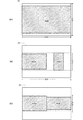
図1Aに示すように、第一モードでは、外部画像A22を配置したウインドウ画像A2
が投写され、投写領域A1内のウインドウ画像A2の背面領域も、ウインドウ画像A2内
の外部画像A22の背面領域の色も黒になる。ここでウインドウ画像とは、投写面におい
て矩形になるようにプロジェクターが扱う最大領域の画像である。投写光源から投写面ま
での距離が投写面上の位置によって異なる場合、プロジェクター内で矩形の画像を描画し
ても、投写面に結ばれる画像はその相似形にならない。このために投写面上で矩形になる
ように調整される画像がウインドウ画像である。
As shown in FIG. 1A, in the first mode, the window image A2 in which the external image A22 is arranged.
Is projected, and the color of the back area of the window image A2 in the projection area A1 and the color of the back area of the external image A22 in the window image A2 is also black. Here, the window image is an image of the maximum area handled by the projector so as to be rectangular on the projection plane. When the distance from the projection light source to the projection plane varies depending on the position on the projection plane, even if a rectangular image is drawn in the projector, the image connected to the projection plane does not have a similar shape. For this reason, an image adjusted to be rectangular on the projection surface is a window image.
図1Bに示すように、第二モードでは、外部画像A22と曲線等の操作入力オブジェク
トA21gを含む操作入力画像A21とを重ねて配置する。第二モードでは、投写領域A
1内のウインドウ画像A2の背面領域の色は第一モードと同じ黒であるが、ウインドウ画
像A2内の外部画像A22の背面領域の色が第一モードと異なる白になる。
As shown in FIG. 1B, in the second mode, the external image A22 and the operation input image A21 including the operation input object A21g such as a curve are arranged so as to overlap each other. In the second mode, the projection area A
The color of the back area of the window image A2 in 1 is the same black as in the first mode, but the color of the back area of the external image A22 in the window image A2 is white different from the first mode.
プロジェクター1は、第二モードでは、操作領域に対する操作を検出すると、操作軌跡
に対応する操作入力オブジェクトA21gを描画して投写する。操作領域は、外部入力画
像A22の2辺と2辺が重なり外部入力画像A2が収まる矩形領域(図1Bの例ではウイ
ンドウ画像A2の領域全体)に設定される。したがって、操作領域の境界線を外部画像A
22の辺の延長上に想定できるため、投写面に対する操作が投写画像に反映される領域を
ユーザーが投写面で認識することが容易である。
In the second mode, when the
Since it can be assumed on the extension of the side of 22, it is easy for the user to recognize on the projection plane an area where an operation on the projection plane is reflected in the projection image.
2.プロジェクターの構成
図2に示すように、プロジェクター1は、第一筐体1aに、光源駆動部16、投写光源
17、液晶ライトバルブ10、液晶駆動部11を表示部として備えるほか、画像信号入力
部14、制御部15、外部記憶151、操作部18、電源部19等を備えている。またプ
ロジェクター1は、第一筐体1aと接続された第二筐体1bに、操作検出部として受信部
21と位置検出部22とを備えている。さらにプロジェクター1は、送信部として電子ペ
ン23を備えている。
2. As shown in FIG. 2, the
投写光源17は、高圧水銀灯、LED(Light emitting diode)、レーザー等によって
構成され、光源駆動部16によって駆動される。画像信号入力部14は、USB端子、イ
ーサネット(登録商標)端子、RS232c端子等の複数種類の入力端子を備え、外部機
器から各種の画像信号が入力される。領域設定部および描画部として機能する制御部15
は、外部記憶151に格納されている制御プログラムを実行することにより、プロジェク
ター1の各部を制御する。また制御部15は、画像信号処理部13とOSD処理部12と
を備え、外部機器から入力された画像信号と位置検出部22から入力される操作位置信号
とに基づいて描画処理を実行し、表示信号としての投写信号を出力する。画像信号処理部
13は、外部機器から入力された画像信号と位置検出部22から入力される操作位置信号
とに基づく描画処理の結果としてウインドウ画像データを出力する。OSD処理部12は
、ウインドウ画像データに基づいて液晶ライトバルブ10に対応する投写信号を出力する
。液晶駆動部11は、OSD処理部12から出力される投写信号を、液晶ライトバルブ1
0の各画素を駆動するためのアナログ信号に変換する。液晶ライトバルブ10は、投写光
源17から放射され図示しないダイクロイックミラーによって分離された赤、緑、青の波
長の光の透過率をそれぞれが画素毎に制御する3つの液晶パネル10a、10b、10c
を備える。操作部18は、OSDメニューを投写する指示を入力するためのメニューキー
181や、OSDメニューの項目を選択するための選択キー182や決定キー183や、
外部電源から電源部19への電力供給をオンおよびオフするための電源スイッチ184を
備える。電源部19は、プロジェクター1の各部に電力を供給する。
The
Controls each part of the
It converts into an analog signal for driving each pixel of 0. The liquid crystal
Is provided. The
A
受信部21は、投写領域A1全体を撮像する赤外線ビデオカメラであって、赤外線波長
の光を受光し、投写領域A1内で電子ペン23の先端が投写面に接触している期間中、電
子ペン23から照射される赤外線波長の光に対応する画像データを出力する。位置検出部
22は、受信部21から出力される画像データを解析することにより、赤外線波長の光の
発光位置、すなわち電子ペン23の位置を検出し、電子ペン23の位置を示す操作位置信
号を出力する。操作位置信号は、制御部15によって、ウインドウ画像A2の座標に変換
される。
The receiving
電子ペン23は、ペン型の筐体に、接触センサー231と発光部232と電源スイッチ
233とを備える。接触センサー231は電子ペン23の先端に設けられ、対象物との接
触状態と非接触状態とを検出する。発光部232は、電子ペン23の先端近くに設けられ
、接触センサー231が対象物との接触状態を検出している期間中、操作信号として赤外
線波長の光を照射する。電源スイッチ233は、図示しない電池から接触センサー231
および発光部232への電力供給を制御するためのスイッチである。電源スイッチ233
は、ペンホルダー234から電子ペン23が取り外されたときと、ペンホルダー234に
電子ペン23が取り付けられたときに自動的に作動する。電源スイッチ233は、ペンホ
ルダー234から電子ペン23が取り外されたときに接触センサー231および発光部2
32への電力供給をオンし、ペンホルダー234に電子ペン23が取り付けられたときに
接触センサー231および発光部232への電力供給をオフにする。ペンホルダー234
は、電子ペン23が取り外された状態と取り付けられた状態とを検出する図示しないセン
サーを備える。
The
And a switch for controlling power supply to the
Operates automatically when the
When the
Includes a sensor (not shown) that detects a state in which the
3.双方向投写方法
3−1.領域設定
まず投写領域内においてウインドウ画像が描画される領域と、ウインドウ画像内におい
て外部画像が描画される領域と、ウインドウ画像内の操作領域との設定について図3を参
照しながら説明する。
制御部15は、画像信号入力部14に新たな外部機器から画像信号が入力されると図3
に示す領域設定処理を開始する(S0)。具体的には、任意の入力端子への画像信号の入
力が開始されたことを画像信号入力部14が検出すると、制御部15はステップS1以後
の領域設定処理を開始する。したがって、画像信号を入力する外部機器が切り替わった場
合には、描画領域及び操作領域が再設定されることになる。
3. 3. Bidirectional projection method 3-1. Region Setting First, the setting of the region in which the window image is drawn in the projection region, the region in which the external image is drawn in the window image, and the operation region in the window image will be described with reference to FIG.
When the image signal is input from the new external device to the image
The area setting process shown in FIG. Specifically, when the image
画像信号入力部14に新たな外部機器から画像信号が入力されると、制御部15は、ウ
インドウ画像内に外部画像をどのように配置するかという画面構成を設定する(S1)。
本実施例では、画面構成として、1つの外部画像をウインドウ画像の中央に配置する一画
面表示、ウインドウ画像の領域を水平方向において2つに等分割し、それぞれの領域に1
つの外部画像を配置する二画面等分割表示、ウインドウ画像を水平方向に2つに不等分割
し、それぞれの領域に1つの外部画像を配置する二画面不等分割表示のいずれかを設定で
きるものとする。具体的には、制御部15は、設定可能な画面構成の選択肢を含むOSD
メニューを投写するための投写信号を出力し、操作部18を用いてユーザーが選択する画
面構成を設定する。
When an image signal is input from the new external device to the image
In this embodiment, as a screen configuration, a single screen display in which one external image is arranged at the center of the window image, an area of the window image is equally divided into two in the horizontal direction, and 1 is assigned to each area.
Can be set to either two-screen equal-divided display in which two external images are arranged, or two-screen unequal-divided display in which a window image is divided into two in the horizontal direction and one external image is arranged in each area. And Specifically, the
A projection signal for projecting the menu is output, and the screen configuration to be selected by the user is set using the
次に制御部15は、画像信号入力部14に入力される画像信号の画面解像度等のフォー
マットを判定する(S2)。
Next, the
次に制御部15は、画面構成と画像信号入力部14に入力される画像信号の解像度と液晶ライトバルブ10の有効領域の解像度(リアル解像度)と台形歪み補正値とに基づいて外部画像の描画領域を設定する(S3)。具体的には、液晶ライトバルブ10の有効領域の解像度と台形歪み補正値とによって、プロジェクター1が投写可能な最大領域である投写領域に対するウインドウ画像の描画領域が決まる。台形歪み補正が実施される場合、ウインドウ画像A2の描画領域は、図4Cに破線A2sで示すようにプロジェクター1が投写可能な最大領域である投写領域A1よりも小さい非矩形になる。なお、台形歪みの補正値は、投写状態を検出した結果に基づいて自動で設定しても良いし、OSDメニューを用いてユーザーに設定させても良い。さらに画面構成によって1つの外部画像を描画できるウインドウ画像内の最大領域が決まる。さらに、その最大領域のアスペクト比と外部画像のアスペクト比とに応じてウインドウ画像内で外部画像の描画領域が決まる。このようにして投写領域A1に対するウインドウ画像A2の描画領域A2sを設定し、ウインドウ画像A2に対する外部画像A22の描画領域A22sを設定することにより、液晶ライトバルブ10の有効領域に対応する投写領域A1に対する外部画像A22の描画領域が設定されることになる。詳細については後述する。
Next, the
次に制御部15は、外部画像の描画領域に基づいて操作領域を設定する(S4)。具体
的には、外部画像の描画領域の向かい合う2辺と操作領域の向かい合う2辺とが重なり、
外部画像の描画領域の他の向かい合う2辺とウインドウ画像の向かい合う2辺とが重なる
矩形領域が操作領域として設定される。詳細については後述する。
Next, the
A rectangular area where the other two opposite sides of the drawing area of the external image and the two opposite sides of the window image overlap is set as the operation area. Details will be described later.
3−2.第一モードの描画処理
制御部15は、外部機器から入力される画像信号に基づいて、設定した描画領域と解像
度が一致するように外部画像を拡大または縮小して描画する。
第一モードでは、制御部15は、投写領域A1内のウインドウ画像A2の背面領域も、
ウインドウ画像A2内の外部画像の背面領域も黒色で描画する。制御部15は、第一モー
ドでは、このように投写領域A1を描画することにより、液晶ライトバルブ10を構成す
る画素に対応する投写信号を出力する。その結果、第一モードでは、図1Aに示すように
、投写領域A1の外部画像A22以外の部分は黒く投写される。なお、破線A2は、ウイ
ンドウ画像A2に対応する領域を示すための仮想的な線であって、実際に投写される線で
はない。
3-2. The drawing process in the first mode The
In the first mode, the
The back area of the external image in the window image A2 is also drawn in black. In the first mode, the
3−3.一画面表示
一画面表示の画面構成が設定され、ウインドウ画像とアスペクト比が一致する画像を表
す画像信号が入力される場合、制御部15は、ウインドウ画像の描画領域そのものを外部
画像の描画領域として設定する。
3-3. Single-screen display When the screen configuration of single-screen display is set and an image signal representing an image having an aspect ratio that matches the window image is input, the
一画面表示の画面構成が設定され、図4Aに示すようにウインドウ画像とアスペクト比
が異なる画像を表す画像信号が入力される場合、制御部15は、図4Bに示すように、外
部画像A22の描画領域A22sとウインドウ画像の2辺が重なり、ウインドウ画像の描
画領域から外部画像A22がはみ出さず、外部画像A22の描画領域A22sとウインド
ウ画像の描画領域の重心が一致するように、外部画像A22の描画領域A22sを設定す
る。
When the screen configuration of one screen display is set and an image signal representing an image having an aspect ratio different from that of the window image is input as illustrated in FIG. 4A, the
3−4.二画面等分割表示
二画面等分割表示の画面構成が設定される場合、制御部15は、図5Aの一点鎖線で示
すようにウインドウ画像A2の領域を左右に二等分する。そして制御部15は、左右いず
れか一方の領域を、第一の外部機器から入力された画像信号に基づく第一の外部画像を描
画する最大領域として割り当て、左右いずれか他方の領域を、第二の外部機器から入力さ
れた画像信号に基づく第二の外部画像を描画する最大領域として割り当てる。
3-4. Two-screen equal-divided display When the screen configuration of two-screen equal-divided display is set, the
画像が縦長になる画像信号が入力される場合、制御部15は、図5Bに破線で示す領域
(テンプレート領域)を定めたテンプレートA22sを用いて外部画像の描画領域を設定
する。テンプレートA22sは、外部画像を描画する左右いずれか一方の最大領域に対し
て、その中央に配置される縦長の領域を、外部画像を収めるべき描画領域として定める。
テンプレートA22sと外部画像のアスペクト比が同じ場合、外部画像のウインドウ画像
A2に対する描画領域はテンプレートA22sの領域そのものとなる。図5Bに示すよう
にテンプレートA22sと外部画像A22のアスペクト比が異なる場合、テンプレートA
22sに収まり、外部画像A22とアスペクト比が一致し、向かい合う二辺がテンプレー
トA22sの向かい合う二辺と重なる領域が外部画像A22のウインドウ画像A2に対す
る描画領域として設定される。
When an image signal that causes the image to be vertically long is input, the
When the aspect ratio of the template A22s and the external image is the same, the drawing area of the external image for the window image A2 is the area of the template A22s itself. When the aspect ratios of the template A22s and the external image A22 are different as shown in FIG.
An area that falls within 22s and has an aspect ratio that matches that of the external image A22 and that has two opposite sides that overlap two opposite sides of the template A22s is set as a drawing area for the window image A2 of the external image A22.
画像が横長になる画像信号が入力される場合、制御部15は、図5Cに示すように、外
部画像を描画する最大領域の向かい合う2辺に対して外部画像A22の2辺が重なり、外
部画像を描画する最大領域から外部画像A22がはみ出さず、外部画像を描画する最大領
域の重心と外部画像A22の重心が一致するように、外部画像A22の描画領域を設定す
る。
When an image signal that causes the image to be horizontally long is input, as illustrated in FIG. 5C, the
3−5.二画面不等分割表示
二画面不等分割表示の画面構成が設定される場合、制御部15は、図6Aの一点鎖線で
示すようにウインドウ画像A2の領域を左右に異なる割合で分割し、それぞれの領域を、
外部画像を描画する最大領域として割り当てる。分割比率は予め決められていても良いし
、ユーザーが設定できるようにしても良い。
3-5. Two-screen unequal division display When the screen configuration of the two-screen unequal division display is set, the
Allocates as the maximum area to draw the external image. The division ratio may be determined in advance or may be set by the user.
画像が縦長になる画像信号が入力される場合、制御部15は、外部画像を描画する最大
領域に対してテンプレートA22sを用いて外部画像の描画領域を設定する。画像が横長
になる画像信号が入力される場合、制御部15は、外部画像を描画する最大領域に収まる
矩形領域であって、その最大領域の向かい合う二辺と向かい合う二辺が重なり、かつ、外
部画像とアスペクト比が一致する矩形領域を外部画像の描画領域として設定する。その結
果、横長の外部画像A22aと縦長の外部画像A22bは、図6Bに示すようにウインド
ウ画像A2に描画される。
When an image signal that makes the image vertically long is input, the
3−6.第一モードから第二モードへの遷移
プロジェクター1は、次に述べる複数のトリガーに応じて第一モードから第二モードへ
遷移する。
第一のトリガーは、画像信号入力部14のUSB端子への外部機器の接続である。制御
部15は画像信号入力部14のUSB端子への外部機器の接続を検出すると、第一モード
から第二モードに遷移する。
3-6. Transition from the first mode to the second mode The
The first trigger is the connection of an external device to the USB terminal of the image
第二のトリガーは、OSDメニューの操作である。操作部18のメニューキー181等
が操作されると、制御部15は例えば図7Aに示すようにモードを選択するためのOSD
メニューA23を最前面に描画したウインドウ画像A2を生成し、項目の選択を待機する
。OSDメニューA23には、第一モードを意味する「標準モード」と第二モードを意味
する「インタラクティブモード」が選択項目として配置される。第一モードにおいて操作
部18の選択キー182と決定キー183を用いて「インタラクティブモード」が選択さ
れると、制御部15は第一モードから第二モードに遷移する。すなわち、OSDメニュー
A23における「インタラクティブモード」の選択は、第一モードから第二モードに遷移
する遷移指示として検出され、選択キー182と決定キー183は遷移指示を検出するた
めの操作スイッチとして機能する。
The second trigger is an OSD menu operation. When the
A window image A2 in which the menu A23 is drawn in the foreground is generated, and the selection of an item is awaited. In the OSD menu A23, “standard mode” meaning the first mode and “interactive mode” meaning the second mode are arranged as selection items. When “interactive mode” is selected using the
第三のトリガーは、電子ペン23の操作である。具体的には、ペンホルダー234から
電子ペン23が取り外されると、ペンホルダー234はこれを検出し、制御部15に通知
する。その結果、制御部15は第一モードから第二モードに遷移する。また、ペンホルダ
ー234から電子ペン23が取り外された後にユーザーがペンホルダー234に戻さずに
電源スイッチ233をオフ操作し、その後再びオン操作したときに第一モードから第二モ
ードに遷移しても良い。この場合、電源スイッチ233のオン操作とオフ操作とを電子ペ
ン23から制御部15に通知する手段が必要になるが、例えば電子ペン23の発光部23
2をその手段として用いることができる。
The third trigger is an operation of the
2 can be used as the means.
第四のトリガーは、投写面の予め決められた領域に対する操作である。投写面の予め決
められた領域に対する操作を第一モードで検出するためには、第一モードでも電子ペン2
3、受信部21および位置検出部22を作動させておく必要がある。また、投写面の予め
決められた領域をユーザーが認識できるように、制御部15は、図7Bに示すように、そ
の領域にモード切替アイコンA21fを第一モードにおいて描画することが好ましい。な
お、第一モードにおいて投写面の予め決められた領域に対する操作を第二モードへの遷移
指示として受け付けるか否かをユーザーが選択できるようにしても良い。
The fourth trigger is an operation on a predetermined area of the projection surface. In order to detect an operation on a predetermined area of the projection surface in the first mode, the electronic pen 2 is used even in the first mode.
3. It is necessary to operate the receiving
3−7.第二モードの描画処理
第二モードにおける外部画像の描画処理は、第一モードと同様である。すなわち、外部
画像が同一である場合、外部画像の描画領域は、第一モードから第二モードに遷移しても
変化しない。
第二モードにおいて、制御部15は、図1Bに示すように投写領域A1内のウインドウ
画像A2の背面領域を黒色で描画し、ウインドウ画像A2内の外部画像A22の背面領域
を白色で描画する。したがって第一モードから第二モードに遷移すると、ウインドウ画像
A2の領域内において外部画像A22の背面領域の色が黒から白に変化する。
3-7. Drawing Process in Second Mode The external image drawing process in the second mode is the same as in the first mode. That is, when the external images are the same, the drawing area of the external image does not change even when the first mode is changed to the second mode.
In the second mode, as shown in FIG. 1B, the
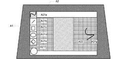
第二モードでは、投写面の操作領域に対する操作に対応する操作入力画像A21が外部
画像A22とともにウインドウ画像A2の白い背面領域の前面に配置される。操作入力画
像A21はプロジェクター1の制御部15が独自に生成する画像である。このため、投写
面の操作領域A24に対する操作に対する操作入力画像A21の応答が速い。なお、操作
入力画像A21の解像度はウインドウ画像A2の解像度と同じである。操作入力画像A2
1の描画領域には、各種のアイコンA21a,A21b,A21c,A21d,A21e
、A21f、A21pと、電子ペン23を用いた操作領域A24Aに対する操作に対応す
る操作入力オブジェクトA21g等が制御部15によって描画される。
In the second mode, the operation input image A21 corresponding to the operation on the operation area of the projection surface is arranged in front of the white back area of the window image A2 together with the external image A22. The operation input image A21 is an image uniquely generated by the
One drawing area includes various icons A21a, A21b, A21c, A21d, and A21e.
, A21f, A21p, and the operation input object A21g corresponding to the operation on the operation area A24A using the
アイコンA21a,A21b,A21c,A21d,A21eは、投写面の操作領域に
対する電子ペン23を用いた操作をどのような図形として操作入力画像A21に反映させ
るかをユーザーに選択させるための領域を示している。すなわち制御部15は、アイコン
A21a,A21b,A21c,A21d,A21eが描画された領域を示す操作位置信
号が位置検出部22から入力されると、それぞれの領域に対応する描画処理を準備する。
例えば、アイコンA21aが投写される領域に電子ペン23の先端が接触すると、制御部
15は、その後の操作領域に対する電子ペン23の先端の接触軌跡を操作入力オブジェク
トA21gとして操作領域の最前面に描画する。アイコンA21bが投写される領域に電
子ペン23の先端が接触すると、制御部15は、操作入力画像A21に描画する線の太さ
を変更する。アイコンA21cが投写される領域に電子ペン23の先端が接触すると、制
御部15は、その後の操作領域A24に対する電子ペン23の先端の接触軌跡の始点と終
点を対角線の両端とする矩形を操作領域の最前面に描画する。アイコンA21dが投写さ
れる領域に電子ペン23の先端が接触すると、制御部15は、その後の操作領域A24に
対する電子ペン23の先端の接触軌跡の始点と終点を対角線とする矩形に内接する楕円を
操作領域の最前面に描画する。アイコンA21eが投写される領域に電子ペン23の先端
が接触すると、制御部15は、その後の操作領域A24に対する電子ペン23の先端の接
触軌跡上において、それ以前の電子ペン23を用いた操作領域A24に対する操作に対応
する操作入力オブジェクトA21gを消去する。またこれらのアイコンA21a,A21
b,A21c,A21d,A21eに対応する描画処理が準備または実行されている期間
中、制御部15は、対応するアイコンA21a,A21b,A21c,A21d,A21
eを強調するための描画をする。そして、第二モードにおいてモード切替アイコンA21
fが投写される領域に電子ペン23の先端が接触すると、制御部15は第一モードに遷移
する。
Icons A21a, A21b, A21c, A21d, and A21e indicate areas for allowing the user to select what figure the operation using the
For example, when the tip of the
During the period in which the drawing process corresponding to b, A21c, A21d, and A21e is prepared or executed, the
Draw to emphasize e. In the second mode, the mode switching icon A21
When the tip of the
3−8.操作領域
一画面表示の画面構成では、図4Bに示すようにウインドウ画像A2よりも外部画像が
縦長の場合、外部画像の描画領域A22sの上下の2辺がウインドウ画像A2の上下の2
辺に重なるため、ウインドウ画像A2の全体が操作領域として設定される。また一画面表
示の画面構成では、図8Aに示すようにウインドウ画像A2よりも外部画像A22が横長
の場合、外部画像A22の描画領域の左右の2辺がウインドウ画像A2の左右の2辺に重
なるため、ウインドウ画像A2の全体が操作領域A24として設定される。そしてウイン
ドウ画像A2と外部画像のアスペクト比が一致する場合にも、ウインドウ画像A2の全体
が操作領域として設定される。すなわち、画面構成が一画面表示の場合、制御部は、ウイ
ンドウ画像A2の全域を操作領域として設定する。
3-8. Operation Area In the one-screen display screen configuration, when the external image is longer than the window image A2 as shown in FIG. 4B, the upper and lower two sides of the external image drawing area A22s are the upper and lower two sides of the window image A2.
Since it overlaps the side, the entire window image A2 is set as the operation area. Further, in the screen configuration of one screen display, when the external image A22 is longer than the window image A2 as shown in FIG. 8A, the left and right sides of the drawing area of the external image A22 overlap the left and right sides of the window image A2. Therefore, the entire window image A2 is set as the operation area A24. Even when the window image A2 and the external image have the same aspect ratio, the entire window image A2 is set as the operation area. That is, when the screen configuration is one-screen display, the control unit sets the entire window image A2 as the operation area.
二画面等分割表示または二画面不等分割表示の画面構成が設定される場合、制御部15は、図8Bおよび図8Cに破線で示すように、2つの外部画像A22a、A22bのうち垂直方向に長い方の外部画像の上下の2辺に上下の2辺が重なり、ウインドウ画像A2の左右の2辺に左右の2辺が重なる矩形の領域を操作領域A24として設定する。したがって二画面等分割表示または二画面不等分割表示の場合、操作領域A24は、ウインドウ画像A2よりも狭い領域になる。制御部15は、投写面の操作領域A24の外側の領域に対して操作がされたとしても、すなわち、操作領域A24の外側の領域に対応する操作位置信号が入力されたとしても、対応する図形をウインドウ画像A2に描画しない。
When the screen configuration of the two-screen equal-divided display or the two-screen unequal-divided display is set, the
既に述べたように制御部15は、第一モードでも第二モードでも、投写領域A1内のウ
インドウ画像A2の背面領域を黒く描画するが、ウインドウ画像A2内の外部画像の背面
領域については、第一モードでは黒く描画し、第二モードでは白く描画する。したがって
第一モードから第二モードに遷移すると、図1Bおよび図9に示すように操作領域の左右
の境界線が、黒色の領域と白色の領域の境界として投写されることになる。
As described above, the
また二画面等分割表示または二画面不等分割表示の画面構成が設定される場合、操作領
域がウインドウ画像A2の描画領域よりも垂直方向に狭くなるため、第二モードにおいて
制御部15は、図9に示すように操作領域の上の境界線A24aと下の境界線A24bを
ウインドウ画像A2に描画する。このため第一モードから第二モードに遷移すると、操作
領域の4辺に境界線が現れることになる。なお、境界線A24a、24bの色は、ウイン
ドウ画像A2の背面領域の色でない色であれば良い。
In addition, when the screen configuration of the two-screen equal division display or the two-screen unequal division display is set, the operation area is narrower in the vertical direction than the drawing area of the window image A2, and thus the
4.ウインドウ画像の印刷
制御部15は、第二モードにおいて印刷指示が入力された場合、ウインドウ画像を印刷
するための印刷データを出力することが可能である。図9に示すアイコンA21pは、印
刷指示を入力するために投写面に電子ペン23の先端を接触させるべき領域を示している
。すなわち制御部15は、アイコンA21pが描画された領域を示す操作位置信号が位置
検出部22から入力されると、その入力を印刷指示として受け付ける。このとき電子ペン
23は印刷指示入力部として機能することになる。
4). When the print instruction is input in the second mode, the window image
第二モードにおいて印刷指示が入力されると、制御部15は、台形補正されていないウ
インドウ画像A2に基づいて印刷データを出力する。具体的には、ウインドウ画像A2を
表すビットマップ形式の画像データを、プロジェクター1に対応するプリンターが処理可
能な形式の印刷データに変換して出力する。印刷データはプロジェクター1に接続された
プリンターに直接出力しても良いし、リムーバブルメモリに出力しても良い。また印刷デ
ータはプリンターに固有のフォーマットでも良いし、PDF等の汎用的なフォーマットで
も良い。
When a print instruction is input in the second mode, the
第二モードにおいては、ウインドウ画像A2内のアイコンA21a,A21b,A21
c,A21d,A21e,A21f、A21p、境界線A24a、A24b、操作領域に
対する操作に対応する文字や図形A21gおよび外部画像A22の背面領域は白く描画さ
れる。このため、ウインドウ画像A2を表すビットマップ形式の画像データを変換して出
力される印刷データに基づいて印刷を実行する場合、プリンターは、アイコンA21a,
A21b,A21c,A21d,A21e,A21f、A21p、操作領域A24Aに対
する操作に対応する文字や図形A21g、外部画像A22以外の領域にインクやトナーを
付着させない。例えば、インクジェットプリンターで印刷を実行する場合、その領域に対
する印刷デューティーはゼロになる。なお、アイコンA21a,A21b,A21c,A
21d,A21e,A21f、A21p、境界線A24a、A24bを印刷対象から除外
してウインドウ画像A2を表すビットマップ形式の画像データを印刷データに変換しても
良い。
In the second mode, the icons A21a, A21b, A21 in the window image A2 are displayed.
c, A21d, A21e, A21f, A21p, boundary lines A24a, A24b, characters and figures A21g corresponding to operations on the operation area, and the back area of the external image A22 are drawn in white. Therefore, when printing is performed based on print data output by converting bitmap-format image data representing the window image A2, the printer uses the icons A21a,
Ink and toner are not attached to areas other than A21b, A21c, A21d, A21e, A21f, A21p, characters and figures A21g corresponding to operations on the operation area A24A, and the external image A22. For example, when printing is performed with an ink jet printer, the print duty for that region is zero. The icons A21a, A21b, A21c, A
The bitmap format image data representing the window image A2 may be converted into print data by excluding 21d, A21e, A21f, A21p, and boundary lines A24a, A24b from the print target.
以上説明した実施例によると、操作領域が外部画像の辺の延長線としてその境界を認識
できる矩形であって、操作領域の境界線が画面に表示されるため、操作領域をユーザーが
画面で認識することが容易になる。さらに外部画像と操作入力画像とを投写する第二モー
ドでは、操作領域内の外部画像の背面領域の色が第一モードの黒と異なる色であるため、
投写面に対する操作が投写画像に反映される操作領域をユーザーが投写面で認識すること
が容易になる。特に操作領域内の外部画像の背面領域の色が、第二モードではホワイトボ
ードや白紙を連想する白になるため、投写面に対する操作が投写画像に反映される操作領
域をユーザーが投写面で認識することがさらに容易になる。さらに、ウインドウ画像内に
操作領域の境界線を投写することにより、ウインドウ画像内で投写面に対する操作が投写
画像に反映される操作領域をユーザーが投写面で認識することがさらに容易になる。そし
て、画像信号を入力する外部機器が切り替わった場合には、描画領域及び操作領域が再設
定され、再設定された操作領域に対応する境界線が投写されることになるため、外部機器
が切り替わって外部画像のアスペクト比や画面構成が変わったとしても、操作領域をユー
ザーが投写面で認識することは容易である。
According to the embodiment described above, the operation area is a rectangle that can recognize the boundary as an extension line of the external image, and the boundary line of the operation area is displayed on the screen. Therefore, the user recognizes the operation area on the screen. Easy to do. Furthermore, in the second mode in which the external image and the operation input image are projected, the color of the back area of the external image in the operation area is different from the black in the first mode.
It becomes easy for the user to recognize on the projection surface the operation area in which the operation on the projection surface is reflected in the projected image. Especially in the second mode, the color of the back area of the external image in the operation area is white, which is reminiscent of a whiteboard or blank sheet, so the user recognizes the operation area in which the operation on the projection plane is reflected in the projection image on the projection plane. It will be easier to do. Furthermore, by projecting the boundary line of the operation area in the window image, it becomes easier for the user to recognize on the projection plane the operation area in which the operation on the projection surface is reflected in the projection image in the window image. When the external device that inputs the image signal is switched, the drawing area and the operation area are reset, and the boundary line corresponding to the reset operation area is projected, so the external device is switched. Even if the aspect ratio or screen configuration of the external image changes, it is easy for the user to recognize the operation area on the projection plane.
また、第二モードへの遷移に伴って操作領域内の外部画像の背面領域の投写形態が変化
するため、投写面に対する操作が投写画像に反映される領域をユーザーが投写面で認識す
ることがさらに容易になる。そして、USB端子に外部機器が接続されると第二モードに
遷移するため、操作領域内の外部画像が配置される領域外の投写形態を変化させるために
ユーザーに要求する操作回数を減らすことができる。また、投写面のアイコンに対する操
作によって操作領域内の外部画像の背面領域の投写形態を変化させるため、ユーザーは投
写面から離れずに操作領域内の外部画像の背面領域の投写形態を変化させることができ、
使い勝手がよい。また電子ペン23の電源スイッチのオン操作で操作領域内の外部画像の
背面領域の投写形態を変化させることができるため、ユーザーに要求する操作回数を減ら
すことができる。
In addition, since the projection mode of the rear area of the external image in the operation area changes with the transition to the second mode, the user can recognize the area where the operation on the projection plane is reflected in the projection image on the projection plane. It becomes easier. When an external device is connected to the USB terminal, the mode is changed to the second mode, so that the number of operations required for the user to change the projection form outside the area where the external image is arranged in the operation area can be reduced. it can. In addition, since the projection mode of the rear area of the external image in the operation area is changed by an operation on the icon on the projection plane, the user can change the projection mode of the rear area of the external image in the operation area without leaving the projection plane. Can
Easy to use. Further, since the projection form of the rear area of the external image in the operation area can be changed by turning on the power switch of the
5.他の実施形態
尚、本発明の技術的範囲は、上述した実施例に限定されるものではなく、本発明の要旨
を逸脱しない範囲内において種々変更を加え得ることは勿論である。
5. Other Embodiments The technical scope of the present invention is not limited to the above-described embodiments, and it goes without saying that various modifications can be made without departing from the scope of the present invention.
例えば、第二モードにおいて、操作領域の境界線をウインドウ画像の4辺に描画しても
良い。ウインドウ画像の外側を操作領域と同じ形態で描画する場合には、操作領域の境界
線をウインドウ画像の4辺に描画することは特に有効である。また、第二モードにおいて
、ウインドウ画像の操作領域の外側を黒色に描画しても良い。この場合、操作領域の境界
線は、黒色の領域と白色の領域の境界として描画されることになる。また、第二モードに
おいて、操作領域内の外部画像の背面領域も第一モードと同じ黒色に描画しても良い。こ
の場合でも、操作領域の境界線を黒以外の色で描画することにより、ユーザーは操作領域
を投写面で認識することができる。
For example, in the second mode, the boundary lines of the operation area may be drawn on the four sides of the window image. When the outside of the window image is drawn in the same form as the operation area, it is particularly effective to draw the boundary lines of the operation area on the four sides of the window image. In the second mode, the outside of the operation area of the window image may be drawn in black. In this case, the boundary line of the operation area is drawn as a boundary between the black area and the white area. In the second mode, the back area of the external image in the operation area may be drawn in the same black color as in the first mode. Even in this case, the user can recognize the operation area on the projection plane by drawing the boundary line of the operation area with a color other than black.
また、第二モードにおいて、白以外の淡い色で操作領域を描画しても良いし、モノクロ
ームでない色で操作領域を描画してもよい。例えばプリンターの1種類のカラーインクや
カラートナーを用いて印刷できる色であって、印刷デューティーが第一モードよりも低く
なる色で描画してもよい。さらに、第二モードにおける操作領域の形態と、印刷指示が入
力された場合に出力される印刷データにおける操作領域の形態とが異なっていても良い。
例えば、第二モードにおける操作領域には、図10に示すように方眼を描画し、印刷デー
タにおける操作領域には方眼を描画しないという方法も採用できる。
In the second mode, the operation area may be drawn with a light color other than white, or the operation area may be drawn with a non-monochrome color. For example, a color that can be printed by using one type of color ink or color toner of the printer, and a color with a print duty lower than that in the first mode may be drawn. Furthermore, the form of the operation area in the second mode may be different from the form of the operation area in the print data output when a print instruction is input.
For example, a method of drawing a grid in the operation area in the second mode as shown in FIG. 10 and not drawing a grid in the operation area in the print data can be employed.
また例えば、操作領域内の外部画像の背面領域の投写形態を第一モードから変化させる
にあたり、第一モードから第二モードに遷移するタイミングでは変化させずに、第二モー
ドでプロジェクターが作動している期間中に何らかのトリガーを設けて変化させても良い
。例えば、OSDメニューの操作やUSB端子への外部機器の接続によって第一モードか
ら第二モードに遷移したタイミングでは、操作領域内の外部画像の背面領域の投写形態を
第一モードから変化させず、第二モードで電子ペンの電源スイッチが操作されたり、第二
モードで電子ペンがペンホルダーから取り外されたり、第二モードで投写面に対する操作
を検出可能な任意の領域に対して最初の操作がなされたり、第二モードでアイコンによっ
て示された所定の領域に対する操作がなされたタイミングにおいて、操作領域内の外部画
像の背面領域の投写形態を第一モードから変化させてもよい。
Also, for example, when changing the projection form of the rear area of the external image in the operation area from the first mode, the projector operates in the second mode without changing at the timing of transition from the first mode to the second mode. Some triggers may be provided and changed during a certain period. For example, at the timing of transition from the first mode to the second mode by operating the OSD menu or connecting an external device to the USB terminal, the projection form of the back area of the external image in the operation area is not changed from the first mode. The power switch of the electronic pen is operated in the second mode, the electronic pen is removed from the pen holder in the second mode, or the first operation is performed on any area that can detect the operation on the projection surface in the second mode. Alternatively, the projection form of the rear area of the external image in the operation area may be changed from the first mode at the timing when the operation is performed on the predetermined area indicated by the icon in the second mode.
また例えば、操作領域の境界線を投写するにあたり、第一モードから第二モードに遷移
するタイミングでは境界線を投写せずに、第二モードでプロジェクターが作動している期
間中に境界線を投写する何らかのトリガーを設けて境界線を投写しても良い。例えば、O
SDメニューの操作やUSB端子への外部機器の接続によって第一モードから第二モード
に遷移したタイミングでは、境界線を投写せず、第二モードで電子ペンの電源スイッチが
操作されたり、第二モードで電子ペンがペンホルダーから取り外されたり、第二モードで
投写面に対する操作を検出可能な任意の領域に対して最初の操作がなされたり、第二モー
ドでアイコンによって示された所定の領域に対する操作がなされたタイミングにおいて、
境界線の投写を開始してもよい。
Also, for example, when projecting the boundary line of the operation area, the boundary line is projected during the period when the projector is operating in the second mode without projecting the boundary line at the timing of transition from the first mode to the second mode. A boundary line may be projected by providing some sort of trigger. For example, O
At the timing of transition from the first mode to the second mode due to the operation of the SD menu or the connection of an external device to the USB terminal, the border line is not projected and the power switch of the electronic pen is operated in the second mode, In the mode, the electronic pen is removed from the pen holder, in the second mode the first operation is performed on any area where the operation on the projection surface can be detected, or in the second mode, the operation is performed on the predetermined area indicated by the icon At the timing when
You may start projecting the boundary line.
また例えば、操作領域はウインドウ画像に内接していても、内接していなくとも良く、
4辺が全てウインドウ画像の辺に重なる矩形領域を操作領域として設定しても良いし、上
下の2辺がウインドウ画像の上下の2辺に重なる矩形領域を操作領域として設定しても良
いし、垂直方向又は水平方向の1辺を除いた3辺がウインドウ画像の辺に重なる矩形領域
を操作領域として設定しても良いし、4辺が全てウインドウ画像の辺よりも内側になる矩
形領域を操作領域として設定しても良い。
For example, the operation area may or may not be inscribed in the window image.
A rectangular area in which all four sides overlap the sides of the window image may be set as the operation area, or a rectangular area in which the upper and lower sides overlap the upper and lower sides of the window image may be set as the operation area. A rectangular area in which three sides excluding one side in the vertical or horizontal direction overlap the side of the window image may be set as the operation area, or a rectangular area in which all four sides are inside the side of the window image is operated. It may be set as an area.
また例えば、投写面に対する操作を検出する手段として、レーザーカーテンを用いても
良いし、赤外線波長以外の波長の光を用いても良い。また、電子ペンのように操作信号を
送信する機能を備えた送信部を用いずに、レーザーカーテンから照射されて指で反射する
赤外線波長の光を検出して投写面に対する操作を検出しても良い。
Further, for example, a laser curtain may be used as means for detecting an operation on the projection surface, or light having a wavelength other than the infrared wavelength may be used. Further, even if an operation on the projection surface is detected by detecting light of an infrared wavelength irradiated from the laser curtain and reflected by a finger without using a transmission unit having a function of transmitting an operation signal like an electronic pen. good.
また例えば、画像を投写するために、1つの液晶パネルを用いて光を変調しても良いし
、反射型の液晶パネルを用いて光を変調しても良いし、DMD(Digital Mirror Device
)を用いて光を変調しても良い。また例えば投写画像を拡大投写するために凸面鏡を用い
ても良いし、鏡を用いなくても良い。また例えば、タッチパネルディスプレイ等の表示装
置に本発明を適用しても良い。
For example, in order to project an image, light may be modulated using a single liquid crystal panel, light may be modulated using a reflective liquid crystal panel, or DMD (Digital Mirror Device) may be used.
) May be used to modulate the light. Further, for example, a convex mirror may be used to enlarge and project a projected image, or a mirror may not be used. For example, the present invention may be applied to a display device such as a touch panel display.
1…プロジェクター、1a…第一筐体、1b…第二筐体、10…液晶ライトバルブ、10
a…液晶パネル、10b…液晶パネル、10c…液晶パネル、11…液晶駆動部、12…
OSD処理部、13…画像信号処理部、14…画像信号入力部、15…制御部、16…光
源駆動部、17…投写光源、18…操作部、19…電源部、21…受信部、22…位置検
出部、23…電子ペン、151…外部記憶、181…メニューキー、182…選択キー、
183…決定キー、184…電源スイッチ、231…接触センサー、232…発光部、2
33…電源スイッチ、234…ペンホルダー、A1…投写領域、A2…ウインドウ画像、
A21…操作入力画像、A21a…アイコン、A21b…アイコン、A21c…アイコン
、A21d…アイコン、A21e…アイコン、A21f…モード切替アイコン、A21g
…操作入力オブジェクトA21p…アイコン、A22…外部画像、A22a…外部画像、
A22b…外部画像、A22s…テンプレート、A23…メニュー、A24…操作領域、
A24a…境界線、A24b…境界線
DESCRIPTION OF
a ... liquid crystal panel, 10b ... liquid crystal panel, 10c ... liquid crystal panel, 11 ... liquid crystal drive unit, 12 ...
OSD processing unit, 13 ... image signal processing unit, 14 ... image signal input unit, 15 ... control unit, 16 ... light source driving unit, 17 ... projection light source, 18 ... operation unit, 19 ... power supply unit, 21 ... receiving unit, 22 ... position detecting unit, 23 ... electronic pen, 151 ... external storage, 181 ... menu key, 182 ... select key,
183 ... key, 184 ... power switch, 231 ... contact sensor, 232 ... light emitting unit, 2
33 ... Power switch, 234 ... Pen holder, A1 ... Projection area, A2 ... Window image,
A21 ... operation input image, A21a ... icon, A21b ... icon, A21c ... icon, A21d ... icon, A21e ... icon, A21f ... mode switching icon, A21g
... operation input object A21p ... icon, A22 ... external image, A22a ... external image,
A22b ... external image, A22s ... template, A23 ... menu, A24 ... operation area,
A24a ... borderline, A24b ... borderline
Claims (5)
前記外部機器から前記画像信号を入力する画像信号入力ステップと、
表示信号に基づいて画像を画面に表示する表示ステップと、
前記画面の前記操作領域に対する操作を検出する操作検出ステップと、
前記画像信号に基づく前記外部画像が収まり前記外部画像と少なくとも一辺が重なる矩形を前記操作領域として前記外部画像に応じて設定する領域設定ステップと、
前記外部画像を表示するための前記表示信号を出力する描画ステップと、
を含み、
前記操作検出ステップは、前記操作領域に対する操作がされた位置である操作位置を検出し、前記操作位置を示す操作位置信号を出力する位置検出ステップを備え、
前記描画ステップは、前記双方向表示装置が前記第一モードで動作する場合、前記操作領域以外の領域と前記操作領域の背景を同じ色とし、前記双方向表示装置が前記第二モードで動作する場合、前記操作領域以外の領域と前記操作領域の背景を異なる色とし、
前記描画ステップは、前記操作領域に対する操作が検出された場合、前記操作位置信号に基づいて、前記操作位置へ操作入力オブジェクトを描画する
双方向表示方法。 An interactive display device that operates in a first mode for displaying an external image based on an image signal input from an external device, and a second mode for combining and displaying an object based on an operation on an operation area and the external image. A bidirectional display method used,
An image signal input step of inputting the image signal from the external device;
A display step for displaying an image on the screen based on the display signal;
An operation detection step of detecting an operation on the operation area of the screen;
A region setting step of setting a rectangle that fits the external image based on the image signal and has at least one side overlapping the external image as the operation region according to the external image;
A drawing step of outputting the display signal for displaying the external image;
Including
The operation detection step includes a position detection step of detecting an operation position that is an operation position on the operation area, and outputting an operation position signal indicating the operation position,
In the drawing step, when the bidirectional display device operates in the first mode, a region other than the operation region and the background of the operation region have the same color, and the bidirectional display device operates in the second mode. The background of the operation area and the background of the operation area are different colors .
The drawing step is a bidirectional display method for drawing an operation input object at the operation position based on the operation position signal when an operation on the operation area is detected .
を表示するための前記表示信号を出力する、
請求項1に記載の双方向表示方法。 In the drawing step, the boundary of the operation area is drawn, and the display signal for displaying the boundary and the external image is output.
The bidirectional display method according to claim 1.
請求項1または2のいずれかに記載の双方向表示方法。 In the region setting step, when the external device that inputs the image signal is switched, the operation region is reset.
The bidirectional display method according to claim 1 or 2 .
請求項1から3のいずれか一項に記載の双方向表示方法。 In the region setting step, the external image is arranged in a rectangular template region, and a rectangle that overlaps at least one side with the template region is set as the operation region according to the external image.
The bidirectional display method according to any one of claims 1 to 3 .
前記外部機器から前記画像信号を入力する画像信号入力部と、
表示信号に基づいて画像を画面に表示する表示部と、
前記画面の前記操作領域に対する操作を検出する操作検出部と、
前記画像信号に基づく前記外部画像が収まり前記外部画像と少なくとも一辺が重なる矩形を前記操作領域として前記外部画像に応じて設定する領域設定部と、
前記外部画像を表示するための前記表示信号を出力する描画部と、
を含み、
前記操作検出部は、前記操作領域に対する操作がされた位置である操作位置を検出し、前記操作位置を示す操作位置信号を出力する位置検出部を更に備え、
前記描画部は、前記双方向表示装置が前記第一モードで動作する場合、前記操作領域以外の領域と前記操作領域の背景を同じ色とし、前記双方向表示装置が前記第二モードで動作する場合、前記操作領域以外の領域と前記操作領域の背景を異なる色とし、
前記描画部は、前記操作領域に対する操作が検出された場合、前記操作位置信号に基づいて、前記操作位置へ操作入力オブジェクトを描画することを特徴とする、
双方向表示装置。 An interactive display device that operates in a first mode for displaying an external image based on an image signal input from an external device and a second mode for combining and displaying an object based on an operation on an operation area and the external image. There,
An image signal input unit for inputting the image signal from the external device;
A display unit for displaying an image on a screen based on a display signal;
An operation detection unit for detecting an operation on the operation area of the screen;
An area setting unit configured to set a rectangle in which the external image based on the image signal is accommodated and at least one side of the external image overlaps as the operation area according to the external image;
A drawing unit for outputting the display signal for displaying the external image;
Including
The operation detection unit further includes a position detection unit that detects an operation position that is an operation position on the operation region and outputs an operation position signal indicating the operation position.
When the interactive display device operates in the first mode, the drawing unit has the same color as the background other than the operation region and the background of the operation region, and the interactive display device operates in the second mode. The background of the operation area and the background of the operation area are different colors.
The drawing unit draws an operation input object at the operation position based on the operation position signal when an operation on the operation area is detected .
Bidirectional display device.
Priority Applications (5)
| Application Number | Priority Date | Filing Date | Title |
|---|---|---|---|
| JP2014075191A JP6565133B2 (en) | 2014-04-01 | 2014-04-01 | Bidirectional display method and bidirectional display device |
| TW104110127A TWI645395B (en) | 2014-04-01 | 2015-03-27 | Two-way display method and two-way display device |
| US15/125,755 US10048905B2 (en) | 2014-04-01 | 2015-03-30 | Interactive display method and interactive display device |
| CN201580016372.6A CN106164828B (en) | 2014-04-01 | 2015-03-30 | Bi-directional display method and bi-directional display device |
| PCT/JP2015/001844 WO2015151505A1 (en) | 2014-04-01 | 2015-03-30 | Bidirectional display method and bidirectional display device |
Applications Claiming Priority (1)
| Application Number | Priority Date | Filing Date | Title |
|---|---|---|---|
| JP2014075191A JP6565133B2 (en) | 2014-04-01 | 2014-04-01 | Bidirectional display method and bidirectional display device |
Publications (3)
| Publication Number | Publication Date |
|---|---|
| JP2015197781A JP2015197781A (en) | 2015-11-09 |
| JP2015197781A5 JP2015197781A5 (en) | 2017-04-06 |
| JP6565133B2 true JP6565133B2 (en) | 2019-08-28 |
Family
ID=54547423
Family Applications (1)
| Application Number | Title | Priority Date | Filing Date |
|---|---|---|---|
| JP2014075191A Expired - Fee Related JP6565133B2 (en) | 2014-04-01 | 2014-04-01 | Bidirectional display method and bidirectional display device |
Country Status (1)
| Country | Link |
|---|---|
| JP (1) | JP6565133B2 (en) |
Families Citing this family (2)
| Publication number | Priority date | Publication date | Assignee | Title |
|---|---|---|---|---|
| US10795467B2 (en) | 2016-12-14 | 2020-10-06 | Nec Display Solutions, Ltd. | Display device, electronic blackboard system, and user interface setting method |
| JP6946690B2 (en) * | 2017-03-24 | 2021-10-06 | カシオ計算機株式会社 | Display device, display method and program |
Family Cites Families (3)
| Publication number | Priority date | Publication date | Assignee | Title |
|---|---|---|---|---|
| JP2008242107A (en) * | 2007-03-28 | 2008-10-09 | Seiko Epson Corp | Projector, dimming control method, dimming control program, and recording medium |
| JP2010139686A (en) * | 2008-12-11 | 2010-06-24 | Seiko Epson Corp | Projector, program, and information storage medium |
| JP5442393B2 (en) * | 2009-10-29 | 2014-03-12 | 日立コンシューマエレクトロニクス株式会社 | Display device |
-
2014
- 2014-04-01 JP JP2014075191A patent/JP6565133B2/en not_active Expired - Fee Related
Also Published As
| Publication number | Publication date |
|---|---|
| JP2015197781A (en) | 2015-11-09 |
Similar Documents
| Publication | Publication Date | Title |
|---|---|---|
| US9684385B2 (en) | Display device, display system, and data supply method for display device | |
| US8943231B2 (en) | Display device, projector, display system, and method of switching device | |
| US9324295B2 (en) | Display device and method of controlling display device | |
| US10416813B2 (en) | Display system, display device, information processing device, and information processing method | |
| US11282422B2 (en) | Display device, and method of controlling display device | |
| JP6051828B2 (en) | Display device and control method of display device | |
| US9830723B2 (en) | Both-direction display method and both-direction display apparatus | |
| US20150279336A1 (en) | Bidirectional display method and bidirectional display device | |
| JP2017182109A (en) | Display system, information processing device, projector, and information processing method | |
| WO2015151505A1 (en) | Bidirectional display method and bidirectional display device | |
| JP6565133B2 (en) | Bidirectional display method and bidirectional display device | |
| JP6364892B2 (en) | Bi-directional projector and bi-directional projection method | |
| JP6273671B2 (en) | Projector, display system, and projector control method | |
| CN106133670B (en) | Bidirectional display method and bidirectional display device | |
| JP6255810B2 (en) | Display device and control method of display device | |
| JP6511725B2 (en) | Interactive display method and interactive display apparatus | |
| JP6056447B2 (en) | Display device and control method of display device | |
| JP6145963B2 (en) | Projector, display system, and projector control method |
Legal Events
| Date | Code | Title | Description |
|---|---|---|---|
| RD04 | Notification of resignation of power of attorney |
Free format text: JAPANESE INTERMEDIATE CODE: A7424 Effective date: 20150114 |
|
| RD04 | Notification of resignation of power of attorney |
Free format text: JAPANESE INTERMEDIATE CODE: A7424 Effective date: 20160617 |
|
| RD03 | Notification of appointment of power of attorney |
Free format text: JAPANESE INTERMEDIATE CODE: A7423 Effective date: 20160628 |
|
| A521 | Request for written amendment filed |
Free format text: JAPANESE INTERMEDIATE CODE: A523 Effective date: 20170303 |
|
| A621 | Written request for application examination |
Free format text: JAPANESE INTERMEDIATE CODE: A621 Effective date: 20170303 |
|
| A131 | Notification of reasons for refusal |
Free format text: JAPANESE INTERMEDIATE CODE: A131 Effective date: 20180605 |
|
| A521 | Request for written amendment filed |
Free format text: JAPANESE INTERMEDIATE CODE: A523 Effective date: 20180803 |
|
| RD05 | Notification of revocation of power of attorney |
Free format text: JAPANESE INTERMEDIATE CODE: A7425 Effective date: 20180904 |
|
| RD03 | Notification of appointment of power of attorney |
Free format text: JAPANESE INTERMEDIATE CODE: A7423 Effective date: 20181107 |
|
| A131 | Notification of reasons for refusal |
Free format text: JAPANESE INTERMEDIATE CODE: A131 Effective date: 20181204 |
|
| A521 | Request for written amendment filed |
Free format text: JAPANESE INTERMEDIATE CODE: A523 Effective date: 20190131 |
|
| TRDD | Decision of grant or rejection written | ||
| A01 | Written decision to grant a patent or to grant a registration (utility model) |
Free format text: JAPANESE INTERMEDIATE CODE: A01 Effective date: 20190702 |
|
| A61 | First payment of annual fees (during grant procedure) |
Free format text: JAPANESE INTERMEDIATE CODE: A61 Effective date: 20190715 |
|
| R150 | Certificate of patent or registration of utility model |
Ref document number: 6565133 Country of ref document: JP Free format text: JAPANESE INTERMEDIATE CODE: R150 |
|
| LAPS | Cancellation because of no payment of annual fees |