EP3124958B1 - Verbundwerkstoff und verfahren zur detektion von kontaminationen auf einer oberfläche eines verbundwerkstoffs - Google Patents
Verbundwerkstoff und verfahren zur detektion von kontaminationen auf einer oberfläche eines verbundwerkstoffs Download PDFInfo
- Publication number
- EP3124958B1 EP3124958B1 EP16181245.8A EP16181245A EP3124958B1 EP 3124958 B1 EP3124958 B1 EP 3124958B1 EP 16181245 A EP16181245 A EP 16181245A EP 3124958 B1 EP3124958 B1 EP 3124958B1
- Authority
- EP
- European Patent Office
- Prior art keywords
- composite material
- reflective
- matrix
- particles
- fibers
- Prior art date
- Legal status (The legal status is an assumption and is not a legal conclusion. Google has not performed a legal analysis and makes no representation as to the accuracy of the status listed.)
- Active
Links
Images

Classifications
-
- G—PHYSICS
- G01—MEASURING; TESTING
- G01N—INVESTIGATING OR ANALYSING MATERIALS BY DETERMINING THEIR CHEMICAL OR PHYSICAL PROPERTIES
- G01N21/00—Investigating or analysing materials by the use of optical means, i.e. using sub-millimetre waves, infrared, visible or ultraviolet light
- G01N21/84—Systems specially adapted for particular applications
- G01N21/88—Investigating the presence of flaws or contamination
- G01N21/94—Investigating contamination, e.g. dust
-
- B—PERFORMING OPERATIONS; TRANSPORTING
- B29—WORKING OF PLASTICS; WORKING OF SUBSTANCES IN A PLASTIC STATE IN GENERAL
- B29C—SHAPING OR JOINING OF PLASTICS; SHAPING OF MATERIAL IN A PLASTIC STATE, NOT OTHERWISE PROVIDED FOR; AFTER-TREATMENT OF THE SHAPED PRODUCTS, e.g. REPAIRING
- B29C70/00—Shaping composites, i.e. plastics material comprising reinforcements, fillers or preformed parts, e.g. inserts
- B29C70/02—Shaping composites, i.e. plastics material comprising reinforcements, fillers or preformed parts, e.g. inserts comprising combinations of reinforcements, e.g. non-specified reinforcements, fibrous reinforcing inserts and fillers, e.g. particulate fillers, incorporated in matrix material, forming one or more layers and with or without non-reinforced or non-filled layers
- B29C70/021—Combinations of fibrous reinforcement and non-fibrous material
- B29C70/025—Combinations of fibrous reinforcement and non-fibrous material with particular filler
-
- B—PERFORMING OPERATIONS; TRANSPORTING
- B29—WORKING OF PLASTICS; WORKING OF SUBSTANCES IN A PLASTIC STATE IN GENERAL
- B29C—SHAPING OR JOINING OF PLASTICS; SHAPING OF MATERIAL IN A PLASTIC STATE, NOT OTHERWISE PROVIDED FOR; AFTER-TREATMENT OF THE SHAPED PRODUCTS, e.g. REPAIRING
- B29C70/00—Shaping composites, i.e. plastics material comprising reinforcements, fillers or preformed parts, e.g. inserts
- B29C70/04—Shaping composites, i.e. plastics material comprising reinforcements, fillers or preformed parts, e.g. inserts comprising reinforcements only, e.g. self-reinforcing plastics
- B29C70/06—Fibrous reinforcements only
- B29C70/08—Fibrous reinforcements only comprising combinations of different forms of fibrous reinforcements incorporated in matrix material, forming one or more layers, and with or without non-reinforced layers
- B29C70/088—Fibrous reinforcements only comprising combinations of different forms of fibrous reinforcements incorporated in matrix material, forming one or more layers, and with or without non-reinforced layers and with one or more layers of non-plastics material or non-specified material, e.g. supports
-
- B—PERFORMING OPERATIONS; TRANSPORTING
- B32—LAYERED PRODUCTS
- B32B—LAYERED PRODUCTS, i.e. PRODUCTS BUILT-UP OF STRATA OF FLAT OR NON-FLAT, e.g. CELLULAR OR HONEYCOMB, FORM
- B32B27/00—Layered products comprising a layer of synthetic resin
- B32B27/06—Layered products comprising a layer of synthetic resin as the main or only constituent of a layer, which is next to another layer of the same or of a different material
-
- B—PERFORMING OPERATIONS; TRANSPORTING
- B32—LAYERED PRODUCTS
- B32B—LAYERED PRODUCTS, i.e. PRODUCTS BUILT-UP OF STRATA OF FLAT OR NON-FLAT, e.g. CELLULAR OR HONEYCOMB, FORM
- B32B27/00—Layered products comprising a layer of synthetic resin
- B32B27/18—Layered products comprising a layer of synthetic resin characterised by the use of special additives
-
- B—PERFORMING OPERATIONS; TRANSPORTING
- B32—LAYERED PRODUCTS
- B32B—LAYERED PRODUCTS, i.e. PRODUCTS BUILT-UP OF STRATA OF FLAT OR NON-FLAT, e.g. CELLULAR OR HONEYCOMB, FORM
- B32B27/00—Layered products comprising a layer of synthetic resin
- B32B27/38—Layered products comprising a layer of synthetic resin comprising epoxy resins
-
- B—PERFORMING OPERATIONS; TRANSPORTING
- B32—LAYERED PRODUCTS
- B32B—LAYERED PRODUCTS, i.e. PRODUCTS BUILT-UP OF STRATA OF FLAT OR NON-FLAT, e.g. CELLULAR OR HONEYCOMB, FORM
- B32B3/00—Layered products comprising a layer with external or internal discontinuities or unevennesses, or a layer of non-planar shape; Layered products comprising a layer having particular features of form
- B32B3/02—Layered products comprising a layer with external or internal discontinuities or unevennesses, or a layer of non-planar shape; Layered products comprising a layer having particular features of form characterised by features of form at particular places, e.g. in edge regions
-
- B—PERFORMING OPERATIONS; TRANSPORTING
- B32—LAYERED PRODUCTS
- B32B—LAYERED PRODUCTS, i.e. PRODUCTS BUILT-UP OF STRATA OF FLAT OR NON-FLAT, e.g. CELLULAR OR HONEYCOMB, FORM
- B32B5/00—Layered products characterised by the non- homogeneity or physical structure, i.e. comprising a fibrous, filamentary, particulate or foam layer; Layered products characterised by having a layer differing constitutionally or physically in different parts
-
- B—PERFORMING OPERATIONS; TRANSPORTING
- B32—LAYERED PRODUCTS
- B32B—LAYERED PRODUCTS, i.e. PRODUCTS BUILT-UP OF STRATA OF FLAT OR NON-FLAT, e.g. CELLULAR OR HONEYCOMB, FORM
- B32B5/00—Layered products characterised by the non- homogeneity or physical structure, i.e. comprising a fibrous, filamentary, particulate or foam layer; Layered products characterised by having a layer differing constitutionally or physically in different parts
- B32B5/02—Layered products characterised by the non- homogeneity or physical structure, i.e. comprising a fibrous, filamentary, particulate or foam layer; Layered products characterised by having a layer differing constitutionally or physically in different parts characterised by structural features of a fibrous or filamentary layer
-
- B—PERFORMING OPERATIONS; TRANSPORTING
- B32—LAYERED PRODUCTS
- B32B—LAYERED PRODUCTS, i.e. PRODUCTS BUILT-UP OF STRATA OF FLAT OR NON-FLAT, e.g. CELLULAR OR HONEYCOMB, FORM
- B32B5/00—Layered products characterised by the non- homogeneity or physical structure, i.e. comprising a fibrous, filamentary, particulate or foam layer; Layered products characterised by having a layer differing constitutionally or physically in different parts
- B32B5/22—Layered products characterised by the non- homogeneity or physical structure, i.e. comprising a fibrous, filamentary, particulate or foam layer; Layered products characterised by having a layer differing constitutionally or physically in different parts characterised by the presence of two or more layers which are next to each other and are fibrous, filamentary, formed of particles or foamed
- B32B5/30—Layered products characterised by the non- homogeneity or physical structure, i.e. comprising a fibrous, filamentary, particulate or foam layer; Layered products characterised by having a layer differing constitutionally or physically in different parts characterised by the presence of two or more layers which are next to each other and are fibrous, filamentary, formed of particles or foamed one layer being formed of particles, e.g. chips, granules, powder
-
- B—PERFORMING OPERATIONS; TRANSPORTING
- B32—LAYERED PRODUCTS
- B32B—LAYERED PRODUCTS, i.e. PRODUCTS BUILT-UP OF STRATA OF FLAT OR NON-FLAT, e.g. CELLULAR OR HONEYCOMB, FORM
- B32B7/00—Layered products characterised by the relation between layers; Layered products characterised by the relative orientation of features between layers, or by the relative values of a measurable parameter between layers, i.e. products comprising layers having different physical, chemical or physicochemical properties; Layered products characterised by the interconnection of layers
- B32B7/04—Interconnection of layers
- B32B7/05—Interconnection of layers the layers not being connected over the whole surface, e.g. discontinuous connection or patterned connection
-
- B—PERFORMING OPERATIONS; TRANSPORTING
- B32—LAYERED PRODUCTS
- B32B—LAYERED PRODUCTS, i.e. PRODUCTS BUILT-UP OF STRATA OF FLAT OR NON-FLAT, e.g. CELLULAR OR HONEYCOMB, FORM
- B32B7/00—Layered products characterised by the relation between layers; Layered products characterised by the relative orientation of features between layers, or by the relative values of a measurable parameter between layers, i.e. products comprising layers having different physical, chemical or physicochemical properties; Layered products characterised by the interconnection of layers
- B32B7/04—Interconnection of layers
- B32B7/06—Interconnection of layers permitting easy separation
-
- B—PERFORMING OPERATIONS; TRANSPORTING
- B32—LAYERED PRODUCTS
- B32B—LAYERED PRODUCTS, i.e. PRODUCTS BUILT-UP OF STRATA OF FLAT OR NON-FLAT, e.g. CELLULAR OR HONEYCOMB, FORM
- B32B7/00—Layered products characterised by the relation between layers; Layered products characterised by the relative orientation of features between layers, or by the relative values of a measurable parameter between layers, i.e. products comprising layers having different physical, chemical or physicochemical properties; Layered products characterised by the interconnection of layers
- B32B7/04—Interconnection of layers
- B32B7/12—Interconnection of layers using interposed adhesives or interposed materials with bonding properties
-
- C—CHEMISTRY; METALLURGY
- C08—ORGANIC MACROMOLECULAR COMPOUNDS; THEIR PREPARATION OR CHEMICAL WORKING-UP; COMPOSITIONS BASED THEREON
- C08J—WORKING-UP; GENERAL PROCESSES OF COMPOUNDING; AFTER-TREATMENT NOT COVERED BY SUBCLASSES C08B, C08C, C08F, C08G or C08H
- C08J5/00—Manufacture of articles or shaped materials containing macromolecular substances
- C08J5/04—Reinforcing macromolecular compounds with loose or coherent fibrous material
-
- C—CHEMISTRY; METALLURGY
- C08—ORGANIC MACROMOLECULAR COMPOUNDS; THEIR PREPARATION OR CHEMICAL WORKING-UP; COMPOSITIONS BASED THEREON
- C08J—WORKING-UP; GENERAL PROCESSES OF COMPOUNDING; AFTER-TREATMENT NOT COVERED BY SUBCLASSES C08B, C08C, C08F, C08G or C08H
- C08J5/00—Manufacture of articles or shaped materials containing macromolecular substances
- C08J5/04—Reinforcing macromolecular compounds with loose or coherent fibrous material
- C08J5/10—Reinforcing macromolecular compounds with loose or coherent fibrous material characterised by the additives used in the polymer mixture
-
- G—PHYSICS
- G01—MEASURING; TESTING
- G01N—INVESTIGATING OR ANALYSING MATERIALS BY DETERMINING THEIR CHEMICAL OR PHYSICAL PROPERTIES
- G01N23/00—Investigating or analysing materials by the use of wave or particle radiation, e.g. X-rays or neutrons, not covered by groups G01N3/00 – G01N17/00, G01N21/00 or G01N22/00
- G01N23/22—Investigating or analysing materials by the use of wave or particle radiation, e.g. X-rays or neutrons, not covered by groups G01N3/00 – G01N17/00, G01N21/00 or G01N22/00 by measuring secondary emission from the material
- G01N23/223—Investigating or analysing materials by the use of wave or particle radiation, e.g. X-rays or neutrons, not covered by groups G01N3/00 – G01N17/00, G01N21/00 or G01N22/00 by measuring secondary emission from the material by irradiating the sample with X-rays or gamma-rays and by measuring X-ray fluorescence
-
- B—PERFORMING OPERATIONS; TRANSPORTING
- B29—WORKING OF PLASTICS; WORKING OF SUBSTANCES IN A PLASTIC STATE IN GENERAL
- B29K—INDEXING SCHEME ASSOCIATED WITH SUBCLASSES B29B, B29C OR B29D, RELATING TO MOULDING MATERIALS OR TO MATERIALS FOR MOULDS, REINFORCEMENTS, FILLERS OR PREFORMED PARTS, e.g. INSERTS
- B29K2995/00—Properties of moulding materials, reinforcements, fillers, preformed parts or moulds
- B29K2995/0018—Properties of moulding materials, reinforcements, fillers, preformed parts or moulds having particular optical properties, e.g. fluorescent or phosphorescent
- B29K2995/003—Reflective
-
- B—PERFORMING OPERATIONS; TRANSPORTING
- B32—LAYERED PRODUCTS
- B32B—LAYERED PRODUCTS, i.e. PRODUCTS BUILT-UP OF STRATA OF FLAT OR NON-FLAT, e.g. CELLULAR OR HONEYCOMB, FORM
- B32B2250/00—Layers arrangement
- B32B2250/02—2 layers
-
- B—PERFORMING OPERATIONS; TRANSPORTING
- B32—LAYERED PRODUCTS
- B32B—LAYERED PRODUCTS, i.e. PRODUCTS BUILT-UP OF STRATA OF FLAT OR NON-FLAT, e.g. CELLULAR OR HONEYCOMB, FORM
- B32B2255/00—Coating on the layer surface
- B32B2255/10—Coating on the layer surface on synthetic resin layer or on natural or synthetic rubber layer
-
- B—PERFORMING OPERATIONS; TRANSPORTING
- B32—LAYERED PRODUCTS
- B32B—LAYERED PRODUCTS, i.e. PRODUCTS BUILT-UP OF STRATA OF FLAT OR NON-FLAT, e.g. CELLULAR OR HONEYCOMB, FORM
- B32B2260/00—Layered product comprising an impregnated, embedded, or bonded layer wherein the layer comprises an impregnation, embedding, or binder material
- B32B2260/02—Composition of the impregnated, bonded or embedded layer
- B32B2260/021—Fibrous or filamentary layer
-
- B—PERFORMING OPERATIONS; TRANSPORTING
- B32—LAYERED PRODUCTS
- B32B—LAYERED PRODUCTS, i.e. PRODUCTS BUILT-UP OF STRATA OF FLAT OR NON-FLAT, e.g. CELLULAR OR HONEYCOMB, FORM
- B32B2260/00—Layered product comprising an impregnated, embedded, or bonded layer wherein the layer comprises an impregnation, embedding, or binder material
- B32B2260/04—Impregnation, embedding, or binder material
- B32B2260/046—Synthetic resin
-
- B—PERFORMING OPERATIONS; TRANSPORTING
- B32—LAYERED PRODUCTS
- B32B—LAYERED PRODUCTS, i.e. PRODUCTS BUILT-UP OF STRATA OF FLAT OR NON-FLAT, e.g. CELLULAR OR HONEYCOMB, FORM
- B32B2262/00—Composition or structural features of fibres which form a fibrous or filamentary layer or are present as additives
- B32B2262/10—Inorganic fibres
- B32B2262/106—Carbon fibres, e.g. graphite fibres
-
- B—PERFORMING OPERATIONS; TRANSPORTING
- B32—LAYERED PRODUCTS
- B32B—LAYERED PRODUCTS, i.e. PRODUCTS BUILT-UP OF STRATA OF FLAT OR NON-FLAT, e.g. CELLULAR OR HONEYCOMB, FORM
- B32B2262/00—Composition or structural features of fibres which form a fibrous or filamentary layer or are present as additives
- B32B2262/10—Inorganic fibres
- B32B2262/108—Rockwool fibres
-
- B—PERFORMING OPERATIONS; TRANSPORTING
- B32—LAYERED PRODUCTS
- B32B—LAYERED PRODUCTS, i.e. PRODUCTS BUILT-UP OF STRATA OF FLAT OR NON-FLAT, e.g. CELLULAR OR HONEYCOMB, FORM
- B32B2307/00—Properties of the layers or laminate
- B32B2307/20—Properties of the layers or laminate having particular electrical or magnetic properties, e.g. piezoelectric
- B32B2307/202—Conductive
-
- B—PERFORMING OPERATIONS; TRANSPORTING
- B32—LAYERED PRODUCTS
- B32B—LAYERED PRODUCTS, i.e. PRODUCTS BUILT-UP OF STRATA OF FLAT OR NON-FLAT, e.g. CELLULAR OR HONEYCOMB, FORM
- B32B2307/00—Properties of the layers or laminate
- B32B2307/30—Properties of the layers or laminate having particular thermal properties
- B32B2307/302—Conductive
-
- B—PERFORMING OPERATIONS; TRANSPORTING
- B32—LAYERED PRODUCTS
- B32B—LAYERED PRODUCTS, i.e. PRODUCTS BUILT-UP OF STRATA OF FLAT OR NON-FLAT, e.g. CELLULAR OR HONEYCOMB, FORM
- B32B2307/00—Properties of the layers or laminate
- B32B2307/40—Properties of the layers or laminate having particular optical properties
- B32B2307/402—Coloured
-
- B—PERFORMING OPERATIONS; TRANSPORTING
- B32—LAYERED PRODUCTS
- B32B—LAYERED PRODUCTS, i.e. PRODUCTS BUILT-UP OF STRATA OF FLAT OR NON-FLAT, e.g. CELLULAR OR HONEYCOMB, FORM
- B32B2307/00—Properties of the layers or laminate
- B32B2307/40—Properties of the layers or laminate having particular optical properties
- B32B2307/416—Reflective
-
- B—PERFORMING OPERATIONS; TRANSPORTING
- B32—LAYERED PRODUCTS
- B32B—LAYERED PRODUCTS, i.e. PRODUCTS BUILT-UP OF STRATA OF FLAT OR NON-FLAT, e.g. CELLULAR OR HONEYCOMB, FORM
- B32B2307/00—Properties of the layers or laminate
- B32B2307/50—Properties of the layers or laminate having particular mechanical properties
- B32B2307/54—Yield strength; Tensile strength
-
- G—PHYSICS
- G01—MEASURING; TESTING
- G01N—INVESTIGATING OR ANALYSING MATERIALS BY DETERMINING THEIR CHEMICAL OR PHYSICAL PROPERTIES
- G01N21/00—Investigating or analysing materials by the use of optical means, i.e. using sub-millimetre waves, infrared, visible or ultraviolet light
- G01N21/62—Systems in which the material investigated is excited whereby it emits light or causes a change in wavelength of the incident light
- G01N21/63—Systems in which the material investigated is excited whereby it emits light or causes a change in wavelength of the incident light optically excited
- G01N21/64—Fluorescence; Phosphorescence
- G01N21/645—Specially adapted constructive features of fluorimeters
- G01N21/6456—Spatial resolved fluorescence measurements; Imaging
- G01N2021/646—Detecting fluorescent inhomogeneities at a position, e.g. for detecting defects
-
- G—PHYSICS
- G01—MEASURING; TESTING
- G01N—INVESTIGATING OR ANALYSING MATERIALS BY DETERMINING THEIR CHEMICAL OR PHYSICAL PROPERTIES
- G01N21/00—Investigating or analysing materials by the use of optical means, i.e. using sub-millimetre waves, infrared, visible or ultraviolet light
- G01N21/84—Systems specially adapted for particular applications
- G01N2021/8472—Investigation of composite materials
-
- G—PHYSICS
- G01—MEASURING; TESTING
- G01N—INVESTIGATING OR ANALYSING MATERIALS BY DETERMINING THEIR CHEMICAL OR PHYSICAL PROPERTIES
- G01N21/00—Investigating or analysing materials by the use of optical means, i.e. using sub-millimetre waves, infrared, visible or ultraviolet light
- G01N21/17—Systems in which incident light is modified in accordance with the properties of the material investigated
- G01N21/21—Polarisation-affecting properties
- G01N21/211—Ellipsometry
-
- G—PHYSICS
- G01—MEASURING; TESTING
- G01N—INVESTIGATING OR ANALYSING MATERIALS BY DETERMINING THEIR CHEMICAL OR PHYSICAL PROPERTIES
- G01N21/00—Investigating or analysing materials by the use of optical means, i.e. using sub-millimetre waves, infrared, visible or ultraviolet light
- G01N21/62—Systems in which the material investigated is excited whereby it emits light or causes a change in wavelength of the incident light
- G01N21/63—Systems in which the material investigated is excited whereby it emits light or causes a change in wavelength of the incident light optically excited
- G01N21/65—Raman scattering
Definitions
- the invention relates to a composite material which comprises fibers and a material matrix. Furthermore, the invention is concerned with a method for the detection of contamination on a surface of a composite material, the composite material having fibers and a material matrix.
- the strength of an adhesive bonded to a composite material is negatively influenced by surface contamination.
- LIBS laser-induced breakdown spectroscopy
- FTIR Fourier transform infrared spectroscopy
- An "electronic nose" as in DE 10 2011 102 055 A1 is still in development and is not suitable for the detection of non-volatile residues of release agents because the contaminants cannot be converted into the gas phase or the temperatures are so high that the composite surface is thermally damaged.
- EP 2 792 470 A1 discloses a method of making a fiber reinforced composite material which comprises applying a paint layer containing pigment to a sheet of a fiber fabric sheet, particularly glass fiber fabric sheet, which comprises drying the paint layer on the sheet and then embedding the sheet in a resin.
- the paint layer can contain metallic flakes or particles that give the final product a three-dimensional aesthetic effect.
- US 5,759,658 discloses a composite panel that includes a resin matrix in which alternate layers of particles and flexible sheets are embedded.
- US 5,849,130 relates to a thermally conductive film in which a multiplicity of fibers are embedded in a polymer matrix material.
- the fibers have a greater thermal conductivity than the polymer matrix and can be coated with a reflective material, as a result of which the fibers act like mirrors arranged in parallel and increasing the light transmission.
- EP 2 730 914 A1 relates to a method for producing a prepreg, which comprises, among other things, impregnating a carbon fiber bundle with a resin and then detecting defects in the resin surface.
- US 2007/0252084 A1 discloses a surface inspection system that includes a tool that uses UV / VIS / IR light to detect the presence of contaminants on the surface of a composite material. For this detection, the different reflection properties of the materials forming the clean surface and of the materials contaminating the surface are compared.
- the invention has for its object to provide a system by means of which contamination on a surface of a composite material can be reliably detected.
- the object is achieved by the composite material according to claim 1 and the method according to claim 6.
- the invention relates to a composite material comprising fibers, a material matrix and a reflection device.
- the reflection device is designed and arranged in such a way that at least one surface area of a surface or side surface of the composite material is reflective.
- the reflection device has a reflective layer which is a reflective fabric and / or a reflective felt.
- the reflective layer is arranged on the fibers.
- the reflective layer is arranged between the material matrix layer and the fibers.
- the reflective fabric is a reflective material.
- the composite material is in particular a fiber composite material, such as a carbon fiber reinforced plastic, also called carbon fiber reinforced plastic (CFRP).
- CFRP carbon fiber reinforced plastic
- the fibers can in particular be carbon fibers.
- the material matrix is formed in particular by a plastic matrix, such as epoxy resin.
- the material matrix is preferably transparent.
- the basic structure of the composite material with respect to the fibers and the material matrix is preferably such as is known from the prior art.
- the fibers are preferably embedded in the material matrix.
- the fibers can be soaked with the liquefied material of the material matrix.
- the reflection device is in particular reflective for electromagnetic waves, the wavelengths of the reflected radiation being able to move in the visible range, in the infrared range and / or in the UV range.
- the reflection device is preferably reflective in such a way that the reflected radiation is suitable for optical measurement methods.
- the optical measurement methods can be, for example, ellipsometry, interferometry, Raman measurements and X-ray fluorescence.
- the reflection device can also be designed to be reflective for X-ray radiation, so that, for example, the reflection device is suitable for X-ray fluorescence.
- the surface of the composite material is formed in particular by the material matrix.
- the surface area of the surface of the composite material can be coherent or formed by several individual areas.
- the entire surface of the composite material can be designed to be reflective, so that the reflection device extends along the entire surface of the composite material.
- the reflection device is provided in particular on the areas of the surface of the composite material to which an adhesive for gluing is applied in a later step.
- a preferred advantage of the invention is that the reflection device can be used to determine contaminations on the surface of the composite material with the aid of optical measuring methods. Until now, this was not possible because the surface of the previously known composite materials was not suitable as a background or background for the extremely sensitive optical measurements.
- the fibers in particular carbon fibers, diffuse radiation or absorb certain wavelengths.
- the material matrix system may emit luminescent light when it is excited with certain energies.
- the reflection device By providing the reflection device, these disadvantages are preferably avoided, since the reflection device provides a reflective layer, so that the reflected radiation required for the optical measurement is no longer diffusely scattered but is reflected. Furthermore, the reflection device in particular prevents certain wavelengths from being absorbed by the fibers, since the light required for the optical measurement no longer reaches the fibers due to the reflection device.
- the luminescence of the material matrix can also be reduced or completely avoided if the reflection device is arranged accordingly, since the reflection device reflects the radiation that stimulates the luminescence before the corresponding sections of the material matrix are reached.
- the material matrix is transparent and particles are arranged in the material matrix, at least some of the particles having a reflective surface to form the reflection device.
- Transparent should in particular mean that the material matrix for the radiation required for the optical measurement is transparent and therefore not absorbing.
- the particles are mixed in particular with the material matrix and are therefore distributed in the composite material.
- the particles are preferably added to improve different properties of the composite.
- the addition of the particles can improve the thermal and / or electrical conductivity of the composite.
- Graphene particles are suitable for this, for example.
- the ductility of the composite material can be improved and / or crack propagation can be reduced or prevented by the addition of particles.
- the particles have in particular a size in the micrometer range, for example a largest diameter between 5 ⁇ m and 40 ⁇ m, in particular between 10 ⁇ m and 30 ⁇ m.
- At least some of the particles are provided with a reflective surface, so that the plurality of reflective particles form the reflection device.
- the proportion of the reflecting particles is selected such that the reflectivity of the reflecting particles is sufficient for the optical measurement.
- all particles can be provided with a reflective surface.
- the particles can either be provided to improve the properties of the composite material, as shown above, and / or to form the reflection device. This alternative can be used to form the reflection device in particular if particles are added in any case to improve the physical properties of the composite material. No separate step is therefore necessary to produce the composite material.
- the particles to form the reflective surface are colored and / or coated, in particular coated with metal.
- the color of the particles is preferably chosen with regard to the wavelength to be reflected.
- the particles can be coated.
- the color of the coating is preferably also selected with a view to the radiation to be reflected.
- a metallic coating is particularly suitable because it is reflective over a wide wavelength range.
- the provision of a coating makes it possible to use particles to form the reflection device which are difficult or impossible to color or whose color is determined by the material of the particles.
- the composite material can alternatively or additionally be provided for adding the particles with a reflective surface.
- the reflective layer is as described above, in particular for the radiation which is used for the optical measurement.
- the reflective layer is particularly between the material matrix layer and the fibers. The radiation for the optical measurement is thus reflected before reaching the fibers, so that the behavior of the fibers, which is disadvantageous for the optical measurement, can be masked out.
- the reflective fabric and / or the reflective felt are particularly impregnated with the material of the material matrix.
- the fibers of the fabric or the felt itself are reflective, or the fabric and / or the felt are provided with a reflective surface.
- the surface of the composite material is designed to be reflective in order to form the reflection device.
- the surface is reflective, so that the radiation required for the optical measurement does not penetrate either into the material matrix or into the fibers.
- the reflective configuration of the surface means that the properties of the fibers and the material matrix, which are disadvantageous for the optical measurement, can be excluded from the measurement.
- the surface of the composite material for forming the reflection device is provided with a reflective layer and / or has a reflective coating.
- the reflection device can only be provided in an area which corresponds in particular to the area which is to be examined for contamination, or over the entire surface.
- the reflective layer or the coating in particular forms the surface of the composite material.
- a reflective layer is applied, which is in particular glued to the surface of the unprocessed composite material.
- the reflective layer can be a film.
- the surface can be coated, for example by applying a material, so that there is a material bond between the reflective coating of the surface.
- the coating can be a color coating or a particle coating.
- the coating is a release agent coating of the peel ply.
- the reflective layer is a release film.
- the separating film is used in particular to make it easier for the composite material to be removed from the mold.
- the composite material has in particular the properties and advantages described above.
- the contaminations on the surface of the composite material can, for example, be release agents for demolding the composite material from its shape.
- the method can be used to determine whether contamination is present, and if so, it can be detected and quantified. If contamination is detected, appropriate countermeasures can be initiated such as removing the contamination or reducing the contamination below a limit.
- the detection of contamination serves to improve structural bonding and / or a bonded repair on the composite material, since if there is contamination, the quality of the bond or the bonded repair is deteriorated.
- the reflection device can be provided in / or on the composite material during the production of the composite material or in a subsequent step.
- the reflection device has in particular the advantages and properties described.
- optical measurement methods can be used to detect contaminations. These are particularly suitable for detecting very thin residues on the surface without damaging the surface.
- Optical measuring methods are to be understood in particular to mean all those methods in which electromagnetic radiation is used.
- optical measurement methods include ellipsometry, interferometry, Raman measurement, X-ray fluorescence and / or laser fluorescence.
- One of the measurement methods described is preferably used.
- several of the optical measurement methods described above can be used, depending on the type of contamination for which the surface of the composite material is to be examined. With the help of the techniques mentioned, in particular the type and amount of release agent residues on the surface of the composite material can be determined.
- particles are produced with a reflective surface and are introduced into the material matrix.
- the particles with the reflective surface can be mixed with particles without a reflective surface.
- the particles are preferably mixed with the liquid material of the material matrix.
- the fibers are then soaked with this particle-material mixture.
- the fibers are provided with a reflective layer in order to provide the reflection device and then the fibers with the reflective layer are provided with the material matrix.
- the fibers are arranged and covered with the reflective layer.
- the combination of fibers and reflective layer is then soaked with the liquid material of the material matrix.
- the reflective layer has in particular the advantages and properties described above.
- the surface of the composite material is provided with a reflective layer and / or coated in a reflective manner in order to provide the reflection device.
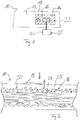
- a composite material 10 has a surface 12.
- a reflection device 16 is provided in the area of a surface area 14 of the surface 12.
- an optical measuring device 20 is provided in order to measure contaminations 18 on the surface 12 in the area 14.
- the optical measuring device 20 has a measuring head 22 and an evaluation unit 24.
- the measuring head 22 is moved over the area 14 and detects contaminations 18 with the aid of optical measuring methods.
- the measuring head 22 is designed to carry out interferometric measurements. This is possible in the area 14 because the composite material 10 is provided with the reflecting reflection device 16 in the area of the area 14, so that the electromagnetic radiation emitted by the measuring head 22 is reflected back into the measuring head 22 by the reflection device 16. The measurement signal is thereby amplified and the luminescence of the composite material 10 is suppressed.
- the contamination 18 is a release agent for demolding the composite material 10 from its shape.
- the contamination 18 has a thickness in the micrometer / nanometer range.
- the surface area 14 is an area of the surface 12 on which an adhesion is to be carried out.
- the quality of the bond is reduced if contaminations 18 are not completely removed.
- Measuring device 20 is used to detect contamination 18. If a contamination 18 is detected, the contamination 18 can be removed after the measurement.
- FIG. 3 shows a section of a cross section of the composite material 10 according to a first embodiment.
- the composite material 10 has fibers 26, a material matrix 28 and a reflection device 16.
- the fibers 26 are arranged in the manner of a fabric and, in the embodiment shown, carbon fibers.
- the material matrix 28 is made of resin, in which particles 30 are incorporated.
- the particles 30 are mixed with the liquid material of the material matrix 28 and then hardened.
- Part of the particles 30 is provided with a reflective surface.
- the particles 30 with the reflective surface form the reflection device 16 according to the first embodiment.
- Mixing the particles 30 with the material matrix 28 thus forms a homogeneous distribution of the particles 30 provided with the reflecting surface, so that these particles 30 form a reflecting layer.
- Incident light, in Fig. 2 represented by the left arrow is reflected on the particles 30, as in FIG Fig. 2 represented by the right arrow.
- Figure 3 shows a section of a cross section through a composite material 10 according to a further embodiment.
- the composite material 10 according to Figure 3 agrees with the composite material 10 according to Figure 2 agree except for the following differences:
- a reflective layer 32 is provided to form the reflection device 16.
- the reflective layer 32 is applied to the fibers 26 on the side of the composite material 10 which is to be examined for contaminations 18.
- the composite material 10 is produced in that the reflective layer 32 is applied to the fibers 26 and the combination of fibers 26 and reflective layer 32 is impregnated with the liquid material of the material matrix 28.
- the reflective layer 32 is a reflective fabric in this embodiment, namely a reflective material. Incident light for optical measurement, which in Figure 3 is represented by the left arrow, is reflected on the reflective layer 32, as shown by the right arrow.
- Figure 4 shows a section of a cross section through a composite material 10 according to a further embodiment.
- the composite according to Figure 4 agrees with the composite materials 10 according to Figures 2 and 3rd except for the following differences.
- the reflection device 16 is in the composite material 10 according to Figure 4 formed by a reflective layer 34.
- the reflective layer 34 is applied to the material matrix 28.
- the reflective layer 34 is a release film in the embodiment shown. Light emitted by the measuring head 22, as indicated by the left arrow in Figure 4 is reflected on the reflective layer 34, as indicated by the right arrow in FIG Figure 4 is shown. Thus, the measuring light does not reach the material matrix 28 or the fibers 26.
- the composite material 10 works as follows: The measuring head 22 emits light in the direction of the composite material 10. In comparison to the composite material 10 from the prior art, however, the light is reflected at the reflection device 16 and is not absorbed or diffusely scattered as in the prior art. The reflected radiation is thus stronger, as a result of which the measurement signal is larger.
- the excitation of luminescence of the material matrix 29 can be prevented since the measuring radiation does not penetrate into the material matrix 28. Even if the measuring light penetrates into the material matrix 28 and generates luminescence, that is reflected light due to the reflectivity of the reflection device 16 so intense that a measurement by means of interferometry is possible.
- the strength of an adhesive is negatively influenced by surface contamination 18 or release agent residues. Mold release agents are used during the manufacture of CFRP composite materials 10. After demolding the composite material 10, the release agents remain as contamination 18 on the surface 12 of the composite material 10. To test whether a surface 12 is free of release agents, a test technique is required which determines the type and amount of the release agent residues on the surface 12.
- particles 30 to the material matrix 28, which can improve the properties of the composite material 10 with regard to different aspects. For example, one hopes to improve the thermal or electrical conductivity by adding graphene. Another approach is to add certain particles 30 to improve the ductility of the composite material 10 and to prevent crack propagation, if necessary. These particles 30 are mixed into the resin of the material matrix 28 and are distributed in the composite material 10.
- the innovation of the invention is now to adapt the surface 12 of the composite material 10 such that it is suitable as a basis / underlay / background for an optical measurement after the production process.
- the resin e.g. metallic
- the reflection was e.g. B. amplify the Raman signal and prevent / attenuate luminescence of the CFRP matrix material 28.
- Other optical layer thickness measurements would also be possible with a defined reflecting surface 12.
- a further possibility of preparing the surface 12 of a CFRP composite material 10 for an optical measurement is at the relevant locations (locations where gluing is to be carried out, or locations where contamination must not be present, i.e. locations where measurement is required).
- the entire composite material 10 is covered with optically transparent resin.
- the coated / treated / inlaid Areas are optically reflective and therefore enable a suitable measurement.
- a further possibility of preparing the surface 12 of the CFRP composite material 10 for an optical measurement is to cover the top or bottom layer of the composite material 10 entirely with a reflective layer 32, or to coat the final GFK / CFRP layer in a reflective manner .
Landscapes
- Chemical & Material Sciences (AREA)
- Health & Medical Sciences (AREA)
- Engineering & Computer Science (AREA)
- Mechanical Engineering (AREA)
- Life Sciences & Earth Sciences (AREA)
- Chemical Kinetics & Catalysis (AREA)
- Medicinal Chemistry (AREA)
- Polymers & Plastics (AREA)
- Organic Chemistry (AREA)
- Composite Materials (AREA)
- Manufacturing & Machinery (AREA)
- Physics & Mathematics (AREA)
- Materials Engineering (AREA)
- Analytical Chemistry (AREA)
- Biochemistry (AREA)
- General Health & Medical Sciences (AREA)
- General Physics & Mathematics (AREA)
- Immunology (AREA)
- Pathology (AREA)
- Investigating, Analyzing Materials By Fluorescence Or Luminescence (AREA)
- Investigating Or Analysing Materials By Optical Means (AREA)
Description
- Die Erfindung betrifft ein Verbundwerkstoff, welcher Fasern und eine Materialmatrix umfasst. Ferner befasst sich die Erfindung mit einem Verfahren zur Detektion von Kontaminationen auf einer Oberfläche eines Verbundwerkstoffs, wobei der Verbundwerkstoff Fasern und eine Materialmatrix aufweist.
- Die Festigkeit einer Klebung bei einem Verbundwerkstoff wird negativ von Oberflächenkontaminationen beeinflusst. Mittels Laser-Induced-Breakdown Spectroscopy (LIBS) ist es möglich, das chemische Element Silikon von Siloxanbasierten Kontaminationen zu unterscheiden. Es ist jedoch nicht möglich, zwischen Silikonen und Silikaten zu unterscheiden, was für die Beurteilung der Oberfläche für nachfolgende Klebevorgänge aber notwendig ist. Fourier-Transform-Infrared-Spectroscopy (FTIR) ist nicht sensitiv genug, um geringe Trennmittelreste nachzuweisen. Eine "elektronische Nase", wie sie in
DE 10 2011 102 055 A1 beschrieben wird, befindet sich noch in Entwicklung und ist für den Nachweis schwerflüchtiger Trennmittelreste nicht geeignet, da die Kontaminationen sich nicht in die Gasphase überführen lassen oder die Temperaturen dabei so hoch sind, dass die Verbundwerkstoffoberfläche thermisch geschädigt wird. -
EP 2 792 470 A1 offenbart ein Verfahren zur Herstellung eines fasererstärkten Verbundmaterials, das das Aufbringen einer Anstrichschicht, die Pigment enthält, auf einen Bogen aus einem Fasergewebebogen, insbesondere Glasfasergewebebogen, das Trocken der Anstrichschicht auf dem Bogen und anschließend das Einbetten des Bogens in ein Harz umfasst. Die Anstrichschicht kann metallische Flocken oder Partikel enthalten, die dem Endprodukt eine dreidimensionale ästhetische Wirkung verleihen. -
US 5,759,658 offenbart eine Verbundplatte, die eine Harzmatrix einschließt, in die abwechselnde Schichten von Partikeln und flexiblen Bögen eingebettet sind. -
US 5,849,130 betrifft einen thermisch leitfähigen Film, bei dem eine Vielzahl von Fasern in ein Polymermatrixmaterial eingebettet sind. Die Fasern haben eine größere Wärmeleitfähigkeit als die Polymermatrix und können mit einer reflektierenden Material beschichtet sein, wodurch die Fasern wie parallel angeordnete, die Lichttransmission erhöhende Spiegel wirken. -
EP 2 730 914 A1 betrifft ein Verfahren zur Herstellung eines Prepregs, das unter anderem das Imprägnieren eines Carbonfaserbündels mit einem Harz und anschließend das Nachweisen von Defekten in der Harzoberfläche umfasst. -
US 2007/0252084 A1 offenbart ein Oberflächenuntersuchungssystem, das ein Werkzeug umfasst, das UV/VIS/IR-Licht verwendet, um das Vorhandensein von Verunreinigungen auf der Oberfläche eines Verbundmaterials nachzuweisen. Für diesen Nachweis werden die unterschiedlichen Reflexionseigenschaften der die saubere Oberfläche bildenden Materialien und der die Oberfläche verunreinigenden Materialien verglichen. - Der Erfindung liegt die Aufgabe zugrunde, ein System bereitzustellen, mittels welchem Kontaminationen auf einer Oberfläche eines Verbundwerkstoffs zuverlässig detektiert werden können.
- Die Aufgabe wird durch den Verbundwerkstoff gemäß Anspruch 1 und das Verfahren gemäß Anspruch 6 gelöst.
- Vorteilhafte Ausgestaltungen der Erfindung sind in den abhängigen Ansprüchen angegeben.
- Die Erfindung betrifft ein Verbundwerkstoff umfassend Fasern, eine Materialmatrix und eine Reflexionsvorrichtung. Die Reflexionsvorrichtung ist derart ausgebildet und angeordnet, dass wenigstens ein Flächenbereich einer Oberfläche oder Seitenfläche des Verbundwerkstoffs reflektierend ist. Die Reflexionsvorrichtung weist eine reflektierende Lage auf, die ein reflektierendes Gewebe und/oder ein reflektierender Filz ist.
- Es ist bevorzugt, dass die reflektierende Lage an den Fasern angeordnet ist.
- Es ist bevorzugt, dass die reflektierende Lage zwischen der Materialmatrixschicht und den Fasern angeordnet ist.
- Es ist bevorzugt, dass das reflektierendes Gewebe ein reflektierender Stoff ist.
- Der Verbundwerkstoff ist insbesondere ein Faserverbundwerkstoff, wie beispielsweise ein kohlenstofffaserverstärkter Kunststoff, auch carbonfaserverstärkter Kunststoff (CFK) genannt.
- Die Fasern können insbesondere Kohlenstofffasern sein. Die Materialmatrix wird insbesondere durch eine Kunststoffmatrix gebildet, wie beispielsweise Epoxidharz. Bevorzugt ist die Materialmatrix transparent ausgebildet.
- Bevorzugt ist der grundlegende Aufbau des Verbundwerkstoffs hinsichtlich den Fasern und der Materialmatrix ein solcher, wie aus dem Stand der Technik bekannt ist. Die Fasern sind bevorzugt in der Materialmatrix eingebettet. Dazu können die Fasern mit dem verflüssigten Werkstoff der Materialmatrix getränkt werden. Insbesondere befindet sich eine durchgehende Schicht der Materialmatrix oberhalb und unterhalb der Fasern.
- Die Reflexionsvorrichtung ist insbesondere für elektromagnetische Wellen reflektierend, wobei sich die Wellenlängen der reflektierten Strahlung im sichtbaren Bereich, im infraroten Bereich und/oder im UV-Bereich bewegen können. Bevorzugt ist die Reflexionsvorrichtung derart reflektierend, dass die reflektierte Strahlung für optische Messverfahren geeignet ist. Die optischen Messverfahren können zum Beispiel Ellipsometrie, Interferometrie, Raman-Messungen sowie Röntgenfluoreszenz sein.
- Alternativ oder zusätzlich, kann die Reflexionsvorrichtung auch für Röntgenstrahlung reflektierend ausgebildet sein, sodass sich beispielsweise die Reflexionsvorrichtung für die Röntgenfluoreszenz eignet.
- Die Oberfläche des Verbundwerkstoffs wird insbesondere durch die Materialmatrix gebildet. Der Flächenbereich der Oberfläche des Verbundwerkstoffs kann zusammenhängend oder durch mehrere Einzelbereiche gebildet sein. Ferner kann die gesamte Oberfläche des Verbundwerkstoffs reflektierend ausgestaltet sein, sodass die Reflexionsvorrichtung sich entlang der gesamten Oberfläche des Verbundwerkstoffs erstreckt. Die Reflexionsvorrichtung wird insbesondere an den Bereichen der Oberfläche des Verbundwerkstoffs vorgesehen, an denen in einem späteren Schritt, ein Klebemittel zum Kleben aufgebracht wird.
- Ein bevorzugter Vorteil der Erfindung ist, dass mittels der Reflexionsvorrichtung Kontaminationen auf der Oberfläche des Verbundwerkstoffs mit Hilfe optischer Messverfahren bestimmt werden können. Bisher war dies nicht möglich, da sich die Oberfläche der bisher bekannten Verbundwerkstoffe nicht als Untergrund oder Hintergrund für die äußerst sensitiven optischen Messungen eignete. Die Fasern, insbesondere Kohlenstofffasern, streuen Strahlung diffus oder absorbieren bestimmte Wellenlängen. Das Materialmatrixsystem emittiert unter Umständen Lumineszenz-Licht, wenn es mit bestimmten Energien angeregt wird.
- Durch das Vorsehen der Reflexionsvorrichtung werden vorzugsweise diese Nachteile vermieden, da die Reflexionsvorrichtung eine reflektierende Schicht bereitstellt, sodass die für die optische Messung benötigte reflektierte Strahlung nicht mehr diffus gestreut wird, sondern reflektiert wird. Ferner verhindert die Reflexionsvorrichtung insbesondere, dass bestimmte Wellenlängen von den Fasern absorbiert werden, da das für die optische Messung benötigte Licht die Fasern aufgrund der Reflexionsvorrichtung nicht mehr erreicht.
- Ferner kann auch die Lumineszenz der Materialmatrix bei entsprechender Anordnung der Reflexionsvorrichtung verringert oder komplett vermieden werden, da durch die Reflexionsvorrichtung die Lumineszenz anregende Strahlung vor Erreichen der entsprechenden Abschnitte der Materialmatrix reflektiert werden.
- Darüber hinaus ist es von Vorteil, dass aufgrund der Reflektivität der Reflexionsvorrichtung besonders viel ausgesandtes Licht reflektiert wird und damit für die Messung zur Verfügung steht. Es ist somit möglich, optische Schichtdickenmessungen, welche Messungen der Kontamination auf der Oberfläche entsprechen, durchzuführen.
- Es ist bevorzugt, dass die Materialmatrix transparent ist und in der Materialmatrix Partikel angeordnet sind, wobei zumindest ein Teil der Partikel zur Bildung der Reflektionsvorrichtung eine reflektierende Oberfläche aufweisen.
- Transparent soll insbesondere bedeuten, dass die Materialmatrix für die für die optische Messung benötigte Strahlung transparent und damit nicht absorbierend ist. Die Partikel werden insbesondere der Materialmatrix beigemischt und sind somit in dem Verbundwerkstoff verteilt.
- Die Partikel werden vorzugsweise zur Verbesserung unterschiedlicher Eigenschaften des Verbundwerkstoffs beigemischt. Zum Beispiel kann durch die Hinzugabe der Partikel die thermische und/oder elektrische Leitfähigkeit des Verbundwerkstoffs verbessert werden. Dazu eignen sich zum Beispiel Graphenpartikel. Ferner kann durch die Zugabe von Partikeln die Duktilität des Verbundwerkstoffs verbessert werden und/oder Rissausbreitungen vermindert oder unterbunden werden. Die Partikel haben insbesondere eine Größe im Mikrometerbereich, beispielsweise einen größten Durchmesser zwischen 5 µm und 40 µm, insbesondere zwischen 10 µm und 30 µm.
- Zumindest ein Teil der Partikel wird mit einer reflektierenden Oberfläche versehen, sodass die Vielzahl der reflektierenden Partikel die Reflexionsvorrichtung bildet. Insbesondere wird der Anteil der reflektierenden Partikel derart gewählt, dass die Reflektivität der reflektierenden Partikel für die optische Messung ausreichend ist. Alternativ können alle Partikel mit einer reflektierenden Oberfläche versehen sein.
- Durch das Einmischen der Partikel in die Materialmatrix ergibt sich somit eine homogene reflektierende Schicht aus reflektierenden Partikel, welche insbesondere in der Materialmatrix vorgesehen ist. Die Partikel können entweder zur Verbesserung der Eigenschaften des Verbundwerkstoffs, sowie oben dargestellt, und/oder zur Bildung der Reflexionsvorrichtung vorgesehen werden. Insbesondere dann, wenn Partikel zur Verbesserung der physikalischen Eigenschaften des Verbundwerkstoffs ohnehin zugegeben werden, kann diese Alternative zur Bildung der Reflexionsvorrichtung verwendet werden. Zur Herstellung des Verbundwerkstoffs ist somit kein separater Schritt notwendig.
- Es ist bevorzugt, dass die Partikel zur Bildung der reflektierenden Oberfläche gefärbt, und/oder beschichtet, insbesondere metallisch beschichtet, sind.
- Vorzugsweise wird die Farbe der Partikel im Hinblick auf die zu reflektierende Wellenlänge gewählt. Alternativ oder zusätzlich können die Partikel beschichtet werden. Die Farbe der Beschichtung wird vorzugsweise ebenfalls im Hinblick auf die zu reflektierende Strahlung gewählt.
- Eine metallische Beschichtung eignet sich besonders, da sie über einen breiten Wellenlängenbereich reflektierend ist. Das Vorsehen einer Beschichtung erlaubt es, Partikel zur Bildung der Reflexionsvorrichtung zu verwenden, welche sich nicht oder nur schwer färben lassen oder deren Farbe durch das Material der Partikel bestimmt ist.
- Der Verbundwerkstoff kann alternativ oder zusätzlich zur Beigabe der Partikel mit einer reflektierenden Oberfläche vorgesehen werden. Die reflektierende Lage ist wie zuvor geschildert, insbesondere für die Strahlung reflektierend, welche für die optische Messung verwendet wird. Die reflektierende Lage ist insbesondere zwischen der Materialmatrixschicht und den Fasern angeordnet. Somit wird die Strahlung für die optische Messung vor Erreichen der Fasern reflektiert, sodass das für die optische Messung nachteilige Verhalten der Fasern ausgeblendet werden kann.
- Das reflektierende Gewebe und/oder der reflektierende Filz sind insbesondere mit dem Material der Materialmatrix getränkt. Zur Entstehung der Reflektivität sind beispielsweise die Fasern des Gewebes oder des Filz selbst reflektierend oder das Gewebe und/oder der Filz sind mit einer reflektierenden Oberfläche versehen.
- Es ist bevorzugt, dass zur Bildung der Reflexionsvorrichtung die Oberfläche des Verbundwerkstoffs reflektierend ausgebildet ist.
- Bei dieser Ausgestaltung ist die Oberfläche reflektierend, sodass die für die optische Messung notwendige Strahlung weder in die Materialmatrix noch zu den Fasern eindringt. Somit kann durch die reflektierende Ausgestaltung der Oberfläche die für die optische Messung nachteiligen Eigenschaften der Fasern und der Materialmatrix von der Messung ausgeschlossen werden.
- Es ist bevorzugt, dass die Oberfläche des Verbundwerkstoffs zur Bildung der Reflexionsvorrichtung mit einer reflektierenden Schicht versehen ist und/oder reflektierend beschichtet ist.
- Wie zuvor geschildert, kann die Reflexionsvorrichtung nur in einem Flächenbereich, welcher insbesondere der Fläche entspricht, welche auf Kontamination untersucht werden soll, oder über die gesamte Oberfläche vorgesehen sein. Die reflektierende Schicht oder die Beschichtung bildet insbesondere die Oberfläche des Verbundwerkstoffs.
- Zur Bildung der reflektierenden Oberfläche wird entweder eine reflektierende Schicht aufgebracht, welche insbesondere auf die Oberfläche des unbearbeiteten Verbundwerkstoffs geklebt wird. Die reflektierende Schicht kann eine Folie sein. Alternativ oder zusätzlich kann die Oberfläche beschichtet werden, beispielsweise durch Aufbringen eines Materials, sodass eine stoffliche Bindung zwischen der Reflexionsbeschichtung der Oberfläche besteht. Beispielsweise kann die Beschichtung eine Farbbeschichtung oder eine Partikelbeschichtung sein. Insbesondere ist die Beschichtung eine Trennmittelbeschichtung des Peel Ply.
- Es ist bevorzugt, dass die reflektierende Schicht eine Trennfolie ist.
- Die Trennfolie dient insbesondere dazu, dass Entformen des Verbundwerkstoffs aus der Form zu erleichtern.
- Ferner betrifft die Erfindung ein Verfahren zur Detektion von Kontaminationen auf einer Oberfläche des Verbundwerkstoffs. Der Verbundwerkstoff weist Fasern und eine Materialmatrix auf. Das Verfahren umfasst die folgenden Schritte:
- Vorsehen einer Reflexionsvorrichtung in dem Verbundwerkstoff wenigstens an einem Flächenbereich der Oberfläche des Verbundwerkstoffs und/oder Vorsehen einer Reflexionsvorrichtung an dem Verbundwerkstoff wenigstens an einem Flächenbereich der Oberfläche des Verbundwerkstoffs durch Versehen der Oberfläche mit einer reflektierenden Schicht und/oder durch reflektierendes Beschichten (10) und
- Detektieren von Kontaminationen auf der Oberfläche des Verbundwerkstoffs (10) mit Hilfe optischer Messverfahren durch Messen der von der Reflexionsvorrichtung (16) reflektierten Strahlung.
- Der Verbundwerkstoff weist insbesondere die oben beschriebenen Eigenschaften und Vorteile auf. Die Kontaminationen auf der Oberfläche des Verbundwerkstoffs können beispielsweise Trennmittel zum Entformen des Verbundwerkstoffs aus seiner Form sein.
- Insbesondere kann mit Hilfe des Verfahrens festgestellt werden, ob eine Kontamination vorliegt, und falls ja, kann diese detektiert und quantifiziert werden. Werden Kontaminationen detektiert, können entsprechende Gegenmaßnahmen eingeleitet werden, beispielsweise das Entfernen der Kontamination oder die Reduktion der Kontamination unter einen Grenzwert. Insbesondere dient die Detektion von Kontaminationen dazu, eine strukturelle Klebung und/oder eine geklebte Reparatur an dem Verbundwerkstoff zu verbessern, da, falls eine Kontamination vorliegt, die Qualität der Klebung oder der geklebten Reparatur verschlechtert ist.
- Das Vorsehen der Reflexionsvorrichtung in/oder an dem Verbundwerkstoff kann während des Herstellens des Verbundwerkstoffs erfolgen oder in einen sich daran anschließenden Schritt. Die Reflexionsvorrichtung weist insbesondere die beschriebenen Vorteile und Eigenschaften auf.
- Durch das Vorsehen der Reflexionsvorrichtung können, wie oben beschrieben, optische Messverfahren zur Detektion von Kontaminationen verwendet werden. Diese eignen sich besonders gut, sehr dünne Rückstände auf der Oberfläche ohne Beschädigung der Oberfläche nachzuweisen. Unter optischen Messverfahren sollen insbesondere all jene Verfahren verstanden werden, bei welchen elektromagnetische Strahlung verwendet wird.
- Es ist bevorzugt, dass die optischen Messverfahren Ellipsometrie, Interferometrie, Raman-Messung, Röntgenfluoreszenz und/oder Laserfluoreszenz umfassen.
- Bevorzugt wird eine der beschriebenen Messverfahren verwendet. Alternativ können mehrere der oberen beschriebenen optischen Messverfahren verwendet werden, je nachdem auf welche Art von Kontamination die Oberfläche des Verbundwerkstoffs untersucht werden soll. Mit Hilfe der genannten Techniken lassen sich insbesondere die Art und Menge von Trennmittelrückständen an der Oberfläche des Verbundwerkstoffs bestimmen.
- Es ist bevorzugt, dass zum Vorsehen der Reflexionsvorrichtung Partikel mit einer reflektierenden Oberfläche hergestellt werden und in die Materialmatrix eingebracht werden.
- Das Herstellen der Partikel mit reflektierenden Oberflächen ist aus dem Stand der Technik bekannt. Wie zuvor geschildert, können die Partikel mit der reflektierenden Oberfläche mit Partikeln ohne reflektierender Oberfläche vermischt werden. Vorzugsweise werden die Partikel mit dem flüssigen Material der Materialmatrix vermischt. Die Fasern werden dann mit diesem Partikel-Material-Gemisch getränkt.
- Es ist bevorzugt, dass die Fasern zum Vorsehen der Reflexionsvorrichtung mit einer reflektierenden Lage bedeckt werden und anschließend die Fasern mit der reflektierenden Lage mit der Materialmatrix versehen werden.
- Insbesondere werden die Fasern angeordnet und mit der reflektierenden Lage bedeckt. Im Anschluss daran wird die Kombination aus Fasern und reflektierender Lage mit dem flüssigen Material der Materialmatrix getränkt. Die reflektierende Lage weist insbesondere die oben beschriebenen Vorteile und Eigenschaften auf.
- Es ist bevorzugt, dass zum Vorsehen der Reflexionsvorrichtung die Oberfläche des Verbundwerkstoffs mit einer reflektierenden Schicht versehen wird und/oder reflektierend beschichtet wird.
- Hinsichtlich der reflektierenden Schicht und der reflektierenden Beschichtung gelten die oben angestellten Überlegungen und Vorteile.
- Im Folgenden wird die Erfindung anhand der beigefügten Zeichnungen näher erläutert. Dabei zeigen:
- Fig. 1
- eine Draufsicht auf einen Verbundwerkstoff;
- Fig. 2
- einen Ausschnitt eines Querschnitts durch den Verbundwerkstoff gemäß
Fig. 1 - Fig. 3
- einen Ausschnitt eines Querschnitts eines Verbundwerkstoffs gemäß einer weiteren Ausführungsform;
- Fig. 4
- ein Ausschnitt eines Querschnitts durch einen Verbundwerkstoff gemäß einer weiteren Ausführungsform;
- Ein Verbundwerkstoff 10 weist eine Oberfläche 12 auf. Im Bereich eines Flächenbereichs 14 der Oberfläche 12 ist eine Reflexionsvorrichtung 16 vorgesehen. Um Kontaminationen 18 auf der Oberfläche 12 in dem Flächenbereich 14 zu messen, ist eine optische Messvorrichtung 20 vorgesehen.
- Die optische Messvorrichtung 20 weist einen Messkopf 22 und eine Auswerteeinheit 24 auf. Der Messkopf 22 wird über den Flächenbereich 14 bewegt und detektiert Kontaminationen 18 mit Hilfe optischer Messverfahren. In der in
Figur 1 gezeigten Ausführungsform ist der Messkopf 22 ausgebildet, Interferometriemessungen durchzuführen. Dies ist in dem Flächenbereich 14 möglich, da der Verbundwerkstoff 10 im Bereich des Flächenbereichs 14 mit der reflektierenden Reflexionsvorrichtung 16 versehen ist, sodass die von dem Messkopf 22 ausgestrahlte elektromagnetische Strahlung von der Reflexionsvorrichtung 16 zurück in den Messkopf 22 reflektiert wird. Dadurch wird das Messsignal verstärkt und die Lumineszenz des Verbundwerkstoffs 10 unterdrückt. - Die Kontamination 18 ist im vorliegenden Fall ein Trennmittel zum Entformen des Verbundwerkstoffs 10 von seiner Form. Die Kontamination 18 weist eine Dicke im Mikrometerbereich/Nanometerbereich auf.
- Der Flächenbereich 14 ist ein Bereich der Oberfläche 12, auf welchem eine Klebung vorgenommen werden soll. Die Qualität der Klebung ist vermindert, wenn Kontaminationen 18 nicht vollständig entfernt werden. Zur Detektion der Kontamination 18 wird die Messvorrichtung 20 verwendet. Wird eine Kontamination 18 detektiert, kann die Kontamination 18 im Anschluss an die Messung entfernt werden.
-
Figur 2 stellt einen Ausschnitt eines Querschnitts des Verbundwerkstoffs 10 gemäß einer ersten Ausführungsform dar. Der Verbundwerkstoff 10 weist Fasern 26, eine Materialmatrix 28 und eine Reflexionsvorrichung 16 auf. Die Fasern 26 sind in der Art eines Gewebes angeordnet und in der gezeigten Ausführungsform Kohlenstofffasern. - Die Materialmatrix 28 ist aus Harz hergestellt, in welche Partikel 30 aufgenommen sind. Zur Herstellung werden die Partikel 30 mit dem flüssigen Material der Materialmatrix 28 vermischt und anschließend ausgehärtet.
- Ein Teil der Partikel 30 ist mit einer reflektierenden Oberfläche versehen. Die Partikel 30 mit der reflektierenden Oberfläche bilden die Reflexionsvorrichtung 16 gemäß der ersten Ausführungsform. Durch die Vermischung der Partikel 30 mit der Materialmatrix 28 bildet sich so eine homogene Verteilung der mit der reflektierenden Oberfläche versehenen Partikel 30, sodass diese Partikel 30 eine reflektierende Schicht bilden. Einfallendes Licht, in
Fig. 2 durch den linken Pfeil dargestellt, wird an den Partikeln 30 reflektiert, wie inFig. 2 durch den rechten Pfeil dargestellt. -
Figur 3 zeigt einen Ausschnitt eines Querschnitts durch einen Verbundwerkstoff 10 gemäß einer weiteren Ausführungsform. Der Verbundwerkstoff 10 gemäßFigur 3 stimmt mit dem Verbundwerkstoff 10 gemäßFigur 2 überein, bis auf die folgenden Unterschiede:
Anstelle der Partikel 30 wird in den Verbundwerkstoff 10 gemäßFigur 3 eine reflektierende Lage 32 zur Bildung der Reflexionsvorrichtung 16 vorgesehen. Die reflektierende Lage 32 ist auf der Seite des Verbundwerkstoffs 10, welche auf Kontaminationen 18 untersucht werden soll, auf die Fasern 26 aufgebracht. - Die Herstellung des Verbundwerkstoffs 10 erfolgt dadurch, dass die reflektierende Lage 32 auf die Fasern 26 aufgebracht wird und die Kombination aus Fasern 26 und reflektierender Lage 32 mit dem flüssigen Material der Materialmatrix 28 getränkt wird.
- Die reflektierende Lage 32 ist in dieser Ausführungsform ein reflektierendes Gewebe und zwar ein reflektierender Stoff. Einfallendes Licht zur optischen Messung, welche in
Figur 3 durch den linken Pfeil dargestellt ist, wird an der reflektierenden Lage 32 reflektiert, wie dies durch den rechten Pfeil dargestellt ist. -
Figur 4 zeigt einen Ausschnitt eines Querschnitts durch einen Verbundwerkstoff 10 gemäß einer weiteren Ausführungsform. Der Verbundwerkstoff gemäßFigur 4 stimmt mit den Verbundwerkstoffen 10 gemäßFiguren 2 und3 bis auf die folgenden Unterschiede überein. - Die Reflexionsvorrichtung 16 wird im Verbundwerkstoff 10 gemäß
Figur 4 durch eine reflektierende Schicht 34 gebildet. Die reflektierende Schicht 34 ist auf die Materialmatrix 28 aufgebracht. Die reflektierende Schicht 34 ist in der gezeigten Ausführungsform eine Trennfolie. Licht, das vom dem Messkopf 22 ausgesandt wird, wie dies durch den linken Pfeil inFigur 4 dargestellt ist, wird an der reflektierenden Schicht 34 reflektiert, wie dies durch den rechten Pfeil inFigur 4 dargestellt ist. Somit gelangt das Messlicht weder zu der Materialmatrix 28 noch zu den Fasern 26. - Der Verbundwerkstoff 10 hat folgende Funktionsweise:
Der Messkopf 22 sendet Licht in Richtung des Verbundwerkstoffes 10 aus. Im Vergleich zum Verbundwerkstoff 10 aus dem Stand der Technik, wird das Licht jedoch an der Reflexionsvorrichtung 16 reflektiert und nicht wie im Stand der Technik absorbiert oder diffus gestreut. Somit ist die reflektierte Strahlung stärker, wodurch das Messsignal größer ist. - Darüber hinaus kann bei der in
Figur 4 gezeigten Ausführungsform des Verbundwerkstoffs 10 die Anregung von Lumineszenz der Materialmatrix 29 verhindert werden, da die Messstrahlung nicht in die Materialmatrix 28 eindringt. Auch wenn das Messlicht in die Materialmatrix 28 eindringt und Lumineszenz erzeugt, ist das reflektierte Licht aufgrund der Reflektivität der Reflexionsvorrichtung 16 derart intensiv, dass eine Messung mittels Interferometrie möglich ist. - Im Folgenden wird die Erfindung nochmals kurz beschrieben:
Im Kontext des structural bonding wird immer wieder der Bedarf an Prüftechniken zur Detektion von Kontaminationen 18 auf Oberflächen 12 von Verbundwerkstoffen 10 genannt. Derzeit befinden sich potentielle Methoden lediglich im Entwicklungsstadium und weisen jeweils spezifische Nachteile auf. Als Anwendungsbereich der Erfindung werden die Fertigung von geklebten Verbundwerkstoffen10 sowie die klebebasierte Reparatur von Verbundwerkstoffen 10 angesehen. - Die Festigkeit einer Klebung wird negativ von oberflächlichen Kontaminationen 18 bzw. Trennmittelrückständen beeinflusst. Während der Fertigung von CFK-Verbundwerkstoffen 10 werden Entformungsmittel verwendet. Nach dem Entformen des Verbundwerkstoffs 10 verbleiben die Trennmittel als Kontamination 18 auf der Oberfläche 12 des Verbundwerkstoffs 10. Zur Prüfung, ob eine Oberfläche 12 trennmittelfrei ist, wird eine Prüftechnik benötigt, welche die Art und Menge der Trennmittelrückstände an der Oberfläche 12 bestimmt.
- Direkte Messungen der Kontaminationen 18 an der Oberfläche 12 erweisen sich aufgrund der geringen Schichtdicken der Trennmittel als schwierig. Allerdings gibt es optische Messverfahren (teilweise aus der Halbleiterindustrie), die sich für die Detektion geringer Schichtdicken / Moleküllagen eignen. Als Beispiel seien hier die Messverfahren der Ellipsometrie, der Interferometrie, der Raman-Messung sowie der Röntgen- und Laser Fluoreszenz genannt.
- Dabei erwiesen sich in der Vergangenheit diese Messmethoden als ungeeignet, da die im Fertigungsprozess entstehende Oberfläche 12 des Verbundwerkstoffs 10 sich nicht als Untergrund/Hintergrund für eine äußerst sensitive, optische Messung eignet. Kohlenstofffasern streuen Strahlung diffus, absorbieren bestimmte Wellenlängen und das Harzsystem der Materialmatrix 28 emittiert Lumineszenz-Licht, wenn es mit bestimmten Energien angeregt wird. Dies alles macht eine optische Messmethode unmöglich.
- Auf der Suche nach neuen, verbesserten Verbundwerkstoffen 10 hat man damit begonnen unter anderem der Materialmatrix 28 Partikel 30 beizumengen, die die Eigenschaften des Verbundwerkstoffs 10 hinsichtlich unterschiedlicher Gesichtspunkte verbessern können. Z. B. erhofft man sich durch Zugabe von Graphen die thermische oder elektrische Leitfähigkeit zu verbessern. Ein anderer Ansatz ist durch Zugabe von bestimmten Partikeln 30, die Duktilität des Verbundwerkstoffs 10 zu verbessern und gegebenenfalls Rissausbreitungen zu unterbinden. Diese Partikel 30 werden dem Harz der Materialmatrix 28 beigemischt und verteilen sich im Verbundwerkstoff 10.
- Die Neuerung der Erfindung liegt nun darin, die Oberfläche 12 des Verbundwerkstoffs 10 so zu adaptieren, dass sie sich nach dem Fertigungsprozess als Grundlage /Unterlage/ Hintergrund für eine optische Messung eignet. Zum Beispiel wäre es möglich die dem Harz beigemischten Partikel 30 so anzupassen / zu färben / zu beschichten (z. B. metallisch), dass die resultierende Oberfläche verspiegelt /reflektierend wird. Die Reflexion wurde z. B. das Ramansignal verstärken und eine Lumineszenz des CFK-Matrixmaterials 28 unterbinden/dämpfen. Auch andere optische Schichtdickenmessungen wären mit einer definiert reflektierenden Oberfläche 12 möglich.
- Eine weitere Möglichkeit die Oberfläche 12 eines CFK-Verbundwerkstoffs 10 für eine optische Messung vorzubereiten ist es, an den relevanten Stellen (Stellen an denen geklebt werden soll, bzw. Stellen an denen keine Kontamination vorliegen darf, also an Stellen an denen gemessen werden muss) eine reflektierenden Schicht auf die oberste Kohlefaserlage aufzubringen, oder einen reflektierenden Stoff /Gewebe /Filz einzulegen. Nach dem Fertigungsschritt ist der gesamte Verbundwerkstoff 10 mit optisch durchlässigem Harz bedeckt. Die beschichteten/behandelten/eingelegten Bereiche sind optisch reflektierend und ermöglichen somit eine geeignete Messung.
- Eine weitere Möglichkeit die Oberfläche 12 des CFK-Verbundwerkstoffs 10 für eine optische Messung vorzubereiten ist es, die oberste bzw. unterste Lage des Verbundwerkstoffs 10 gänzlich mit einer reflektierenden Lage 32 zu bedecken, bzw. die abschließende GFK- / CFK-Lage reflektierend zu beschichten.
- Zusammenfassend gibt es drei Möglichkeiten zur Anpassung des Verbundwerkstoffs 10:
- 1. Anpassung der Materialmatrix 28 durch geeignete Partikel 30;
- 2. Anpassung durch geeignetes Beschichten der obersten/untersten/äußeren Schicht/Lage und/oder durch Einlegen von geeigneten Schichten 32 / Stoffen / beschichteten Lagen. Nach der Fertigung können optische Messmethoden eingesetzt werden, da die äußere Harzschicht transparent ist.
- 3. Anpassung des Verarbeitungshilfsstoffs (Partikel/Farbe in Trennmittelbeschichtung des Peel Ply, Trennfolie bzw. Werkzeugtrennmittels).
-
- 10
- Verbundwerkstoff
- 12
- Oberfläche
- 14
- erster Flächenbereich
- 16
- Reflektionsvorrichtung
- 18
- Kontamination
- 20
- Messvorrichtung
- 22
- Messkopf
- 24
- Auswerteeinheit
- 26
- Fasern
- 28
- Materialmatrix
- 30
- Partikel
- 32
- Reflektierende Lage
- 34
- Reflektierende Schicht
Claims (13)
- Verbundwerkstoff (10) umfassend Fasern (26), eine Materialmatrix (28) und eine Reflexionsvorrichtung (16), welche derart ausgebildet und angeordnet ist, dass wenigstens ein Flächenbereich einer Oberfläche des Verbundwerkstoffs (10) reflektierend ist,
dadurch gekennzeichnet, dass
die Reflexionsvorrichtung (16) eine reflektierende Lage (32) aufweist, die ein reflektierendes Gewebe und/oder ein reflektierender Filz ist. - Verbundwerkstoff 10) nach Anspruch 1, dadurch gekennzeichnet, dass die reflektierende Lage (2) an den Fasern (26) angeordnet ist.
- Verbundwerkstoff (10) nach Anspruch 1 oder 2, dadurch gekennzeichnet, dass die reflektierende Lage (2) zwischen der Materialmatrixschicht (28) und den Fasern (26) angeordnet ist.
- Verbundwerkstoff (10) nach einem der vorhergehenden Ansprüche, dadurch gekennzeichnet, dass die Materialmatrix (28) transparent ist und in der Materialmatrix (28) Partikel (30) angeordnet sind, wobei zumindest ein Teil der Partikel (30) zur Bildung der Reflektionsvorrichtung (16) eine reflektierende Oberfläche (12) aufweisen.
- Verbundwerkstoff (10) nach Anspruch 4, dadurch gekennzeichnet, dass die Partikel (30) zur Bildung der reflektierenden Oberfläche (12) gefärbt und/oder beschichtet, insbesondere metallisch beschichtet, sind.
- Verbundwerkstoff (10) nach einem der voranstehenden Ansprüche, dadurch gekennzeichnet, dass zur Bildung der Reflektionsvorrichtung (16) zusätzlich die Oberfläche (12) des Verbundwerkstoffs (10) reflektierend ausgebildet ist.
- Verbundwerkstoff (10) nach Anspruch 6, dadurch gekennzeichnet, dass die Oberfläche (12) mit einer reflektierenden Schicht (34) versehen ist und/oder reflektierend beschichtet ist.
- Verbundwerkstoff (10) nach Anspruch 7, dadurch gekennzeichnet, dass die reflektierende Schicht (34) eine Trennfolie ist.
- Verfahren zur Detektion von Kontaminationen (18) auf einer Oberfläche (12) eines Verbundwerkstoffs (10), der Fasern (26) und eine Materialmatrix (28) aufweist, wobei das Verfahren den folgenden Schritt umfasst:Detektieren von Kontaminationen (18) auf der Oberfläche (12) des Verbundwerkstoffs (10) mit Hilfe optischer Messverfahren durch Messen der von der Reflexionsvorrichtung (16) reflektierten Strahlung,dadurch gekennzeichnet,dass das Verfahren auch den Schritt des Vorsehens einer Reflektionsvorrichtung (16) in und/oder an dem Verbundwerkstoff (10) an einem ersten Flächenbereich (14) der Oberfläche (12) des Verbundwerkstoffs umfasst.
- Verfahren nach Anspruch 9, dadurch gekennzeichnet, dass die optischen Messverfahren Ellipsometrie, Interferometrie, Raman-Messung, Röntgenfluoreszenz und/oder Laserfluoreszenz umfassen.
- Verfahren nach einem der Ansprüche 9 und 10, dadurch gekennzeichnet, dass die Kontamination (18) ein Trennmittel ist, das bei der Herstellung des Verbundwerkstoffs (10) verwendet wird.
- Verfahren nach einem der Ansprüche 9 bis 11, dadurch gekennzeichnet, dass zum Vorsehen der Reflektionsvorrichtung (16) Partikel (30) mit einer reflektierenden Oberfläche (12) hergestellt werden und in die Materialmatrix (28) eingebracht werden.
- Verfahren nach einem der Ansprüche 9 bis 12, dadurch gekennzeichnet, dass zum Vorsehen der Reflektionsvorrichtung (16) die Fasern (26) mit einer reflektierenden Lage (32) bedeckt werden und anschließend die Fasern (26) mit der reflektierenden Lage (32) mit der Materialmatrix (28) versehen werden.
Applications Claiming Priority (1)
| Application Number | Priority Date | Filing Date | Title |
|---|---|---|---|
| DE102015009729.6A DE102015009729A1 (de) | 2015-07-31 | 2015-07-31 | Verbundwerkstoff und Verfahren zur Detektion von Kontaminationen auf einer Oberfläche eines Verbundwerkstoffs |
Publications (2)
| Publication Number | Publication Date |
|---|---|
| EP3124958A1 EP3124958A1 (de) | 2017-02-01 |
| EP3124958B1 true EP3124958B1 (de) | 2020-04-08 |
Family
ID=56684458
Family Applications (1)
| Application Number | Title | Priority Date | Filing Date |
|---|---|---|---|
| EP16181245.8A Active EP3124958B1 (de) | 2015-07-31 | 2016-07-26 | Verbundwerkstoff und verfahren zur detektion von kontaminationen auf einer oberfläche eines verbundwerkstoffs |
Country Status (2)
| Country | Link |
|---|---|
| EP (1) | EP3124958B1 (de) |
| DE (1) | DE102015009729A1 (de) |
Citations (2)
| Publication number | Priority date | Publication date | Assignee | Title |
|---|---|---|---|---|
| US20070252084A1 (en) * | 2006-04-24 | 2007-11-01 | Space Micro, Inc. | Portable composite bonding inspection system |
| EP2730914A1 (de) * | 2011-10-28 | 2014-05-14 | Toray Industries, Inc. | Verfahren zur herstellung von prepreg |
Family Cites Families (7)
| Publication number | Priority date | Publication date | Assignee | Title |
|---|---|---|---|---|
| GB1202330A (en) * | 1968-07-04 | 1970-08-12 | Canrad Prec Ind Inc | Retro-reflector and method of making the same |
| DE3942226C2 (de) * | 1989-12-21 | 1993-10-14 | Bayer Ag | Verfahren zum optischen Prüfen von Faserverbundwerkstoffen |
| US5759658A (en) * | 1996-04-26 | 1998-06-02 | Tables International Corporation | Composite panels, articles incorporating same and method |
| US5695847A (en) * | 1996-07-10 | 1997-12-09 | Browne; James M. | Thermally conductive joining film |
| US7424902B2 (en) * | 2004-11-24 | 2008-09-16 | The Boeing Company | In-process vision detection of flaw and FOD characteristics |
| DE102011102055B8 (de) | 2011-05-19 | 2013-04-25 | Eads Deutschland Gmbh | Vorrichtung zur Prüfung eines Faserverbundbauteils auf Kontaminationen |
| EP2792470A1 (de) * | 2013-04-15 | 2014-10-22 | BlackBerry Limited | Faserverstärktes Vliesverbundmaterial und Verfahren zur Herstellung davon |
-
2015
- 2015-07-31 DE DE102015009729.6A patent/DE102015009729A1/de not_active Withdrawn
-
2016
- 2016-07-26 EP EP16181245.8A patent/EP3124958B1/de active Active
Patent Citations (2)
| Publication number | Priority date | Publication date | Assignee | Title |
|---|---|---|---|---|
| US20070252084A1 (en) * | 2006-04-24 | 2007-11-01 | Space Micro, Inc. | Portable composite bonding inspection system |
| EP2730914A1 (de) * | 2011-10-28 | 2014-05-14 | Toray Industries, Inc. | Verfahren zur herstellung von prepreg |
Also Published As
| Publication number | Publication date |
|---|---|
| DE102015009729A1 (de) | 2017-02-02 |
| EP3124958A1 (de) | 2017-02-01 |
Similar Documents
| Publication | Publication Date | Title |
|---|---|---|
| EP3280997B1 (de) | Verfahren zur bestimmung der abriebfestigkeit von mindestens einer auf einer trägerplatte angeordneten verschleissschicht | |
| EP3163293B1 (de) | Verfahren zum nachweis von oberflächenrückständen auf bauteilen mittels uv-bestrahlung | |
| DE69920246T2 (de) | Lumineszenter reisslack in der dehnungsanalyse | |
| WO2014191491A1 (de) | Verfahren zur bestimmung des feuchtegehaltes einer harzschicht auf einer trägerplatte | |
| DE19541028A1 (de) | Kennzeichnung für mit einem Effektlack lackierte Gegenstände und Verfahren zur Herstellung der Kennzeichnung | |
| DE102020103067B4 (de) | Verfahren zum Verifizieren eines Qualitätssicherungssystems | |
| EP3163294B1 (de) | Verfahren zum nachweis von oberflächenverunreinigungen mittels röntgenfluoreszenzanalyse | |
| DE102010031919A1 (de) | Messsonde für einen Sensor zur Analyse eines Mediums mittels Infrarotspektroskopie | |
| DE102009037541A1 (de) | Verfahren und Vorrichtung zur Messung des Härtungsgrades von UV-härtenden Farben und Lacken | |
| EP0842414B1 (de) | Verfahren und vorrichtung zur charakterisierung lackierter oberflächen | |
| DE19605520C1 (de) | Verfahren und Vorrichtung zur Charakterisierung lackierter Oberflächen | |
| DE102012018939A1 (de) | Verfahren zur optischen Erkennung einer Deformation eines Halbzeugs während einer Umformung | |
| DE102012200767B4 (de) | Verfahren zur zerstörungsfreien Prüfung von Werkstückoberflächen | |
| EP1715319B1 (de) | Verfahren zur Bestimmung der Druckverteilung über einer Oberfläche und druckempfindliche Farbe zur Verwendung dabei | |
| DE102012110699A1 (de) | Verfahren und Kit zur aktiven Thermografie | |
| WO2011137995A2 (de) | Verfahren und vorrichtung zur messung von verbindungseigenschaften eines werkstoffverbundes | |
| DE102014219496B3 (de) | Verfahren und Vorrichtung zur Bestimmung einer Barrierewirkung einer Beschichtung auf einem Substrat | |
| DE19611062C1 (de) | Verfahren zur Charakterisierung mehrschichtig lackierter Oberflächen | |
| EP3124958A1 (de) | Verbundwerkstoff und verfahren zur detektion von kontaminationen auf einer oberfläche eines verbundwerkstoffs | |
| DE102010023655A1 (de) | Verfahren zur automatisierten Beurteilung von Korrosionsschäden nach zerstörungsfreier Prüfung mittels Impulsthermographie | |
| EP3753720A1 (de) | Verfahren zum dreidimensionalen erfassen von fasermaterial mittels terahertzstrahlung sowie faserlegeanlage hierzu | |
| EP1380832B1 (de) | Verfahren zur Bestimmung der Hafteigenschaften von Materialien | |
| DE102021100216A1 (de) | Verfahren zur Überwachung der Bedeckung einer Formoberfläche eines Formwerkzeugs mit einem Prozesshilfsstoff in einem Gießprozess | |
| DE102020102800A1 (de) | Verfahren und Vorrichtung zum Ermitteln einer Applikationseigenschaft und Verfahren zur Herstellung einer Faserpreform | |
| DE102016223077A1 (de) | Vorrichtung, Messanordnung und Verfahren zur Bestimmung einer dielektrischen Eigenschaft einer Messprobe, Verwendung der Messanordnung |
Legal Events
| Date | Code | Title | Description |
|---|---|---|---|
| PUAI | Public reference made under article 153(3) epc to a published international application that has entered the european phase |
Free format text: ORIGINAL CODE: 0009012 |
|
| STAA | Information on the status of an ep patent application or granted ep patent |
Free format text: STATUS: THE APPLICATION HAS BEEN PUBLISHED |
|
| AK | Designated contracting states |
Kind code of ref document: A1 Designated state(s): AL AT BE BG CH CY CZ DE DK EE ES FI FR GB GR HR HU IE IS IT LI LT LU LV MC MK MT NL NO PL PT RO RS SE SI SK SM TR |
|
| AX | Request for extension of the european patent |
Extension state: BA ME |
|
| STAA | Information on the status of an ep patent application or granted ep patent |
Free format text: STATUS: REQUEST FOR EXAMINATION WAS MADE |
|
| 17P | Request for examination filed |
Effective date: 20170727 |
|
| RBV | Designated contracting states (corrected) |
Designated state(s): AL AT BE BG CH CY CZ DE DK EE ES FI FR GB GR HR HU IE IS IT LI LT LU LV MC MK MT NL NO PL PT RO RS SE SI SK SM TR |
|
| STAA | Information on the status of an ep patent application or granted ep patent |
Free format text: STATUS: EXAMINATION IS IN PROGRESS |
|
| 17Q | First examination report despatched |
Effective date: 20181109 |
|
| REG | Reference to a national code |
Ref country code: DE Ref legal event code: R079 Ref document number: 502016009437 Country of ref document: DE Free format text: PREVIOUS MAIN CLASS: G01N0021840000 Ipc: B32B0005020000 |
|
| RIC1 | Information provided on ipc code assigned before grant |
Ipc: B32B 5/30 20060101ALI20190516BHEP Ipc: B32B 27/18 20060101ALI20190516BHEP Ipc: B32B 7/12 20060101ALI20190516BHEP Ipc: B32B 7/06 20190101ALI20190516BHEP Ipc: B32B 27/06 20060101ALI20190516BHEP Ipc: G01N 21/64 20060101ALI20190516BHEP Ipc: G01N 21/65 20060101ALI20190516BHEP Ipc: G01N 21/94 20060101ALI20190516BHEP Ipc: G01N 23/223 20060101ALI20190516BHEP Ipc: B32B 7/05 20190101ALI20190516BHEP Ipc: B32B 27/38 20060101ALI20190516BHEP Ipc: B29C 70/02 20060101ALI20190516BHEP Ipc: C08J 5/10 20060101ALI20190516BHEP Ipc: B29C 70/08 20060101ALI20190516BHEP Ipc: B32B 5/02 20060101AFI20190516BHEP Ipc: B32B 3/02 20060101ALI20190516BHEP Ipc: G01N 21/84 20060101ALI20190516BHEP Ipc: C08J 5/04 20060101ALI20190516BHEP Ipc: G01N 21/21 20060101ALI20190516BHEP |
|
| GRAP | Despatch of communication of intention to grant a patent |
Free format text: ORIGINAL CODE: EPIDOSNIGR1 |
|
| STAA | Information on the status of an ep patent application or granted ep patent |
Free format text: STATUS: GRANT OF PATENT IS INTENDED |
|
| INTG | Intention to grant announced |
Effective date: 20190710 |
|
| GRAJ | Information related to disapproval of communication of intention to grant by the applicant or resumption of examination proceedings by the epo deleted |
Free format text: ORIGINAL CODE: EPIDOSDIGR1 |
|
| STAA | Information on the status of an ep patent application or granted ep patent |
Free format text: STATUS: EXAMINATION IS IN PROGRESS |
|
| INTC | Intention to grant announced (deleted) | ||
| GRAP | Despatch of communication of intention to grant a patent |
Free format text: ORIGINAL CODE: EPIDOSNIGR1 |
|
| STAA | Information on the status of an ep patent application or granted ep patent |
Free format text: STATUS: GRANT OF PATENT IS INTENDED |
|
| INTG | Intention to grant announced |
Effective date: 20191024 |
|
| GRAS | Grant fee paid |
Free format text: ORIGINAL CODE: EPIDOSNIGR3 |
|
| GRAA | (expected) grant |
Free format text: ORIGINAL CODE: 0009210 |
|
| STAA | Information on the status of an ep patent application or granted ep patent |
Free format text: STATUS: THE PATENT HAS BEEN GRANTED |
|
| AK | Designated contracting states |
Kind code of ref document: B1 Designated state(s): AL AT BE BG CH CY CZ DE DK EE ES FI FR GB GR HR HU IE IS IT LI LT LU LV MC MK MT NL NO PL PT RO RS SE SI SK SM TR |
|
| REG | Reference to a national code |
Ref country code: CH Ref legal event code: EP Ref country code: AT Ref legal event code: REF Ref document number: 1253809 Country of ref document: AT Kind code of ref document: T Effective date: 20200415 |
|
| REG | Reference to a national code |
Ref country code: DE Ref legal event code: R096 Ref document number: 502016009437 Country of ref document: DE |
|
| REG | Reference to a national code |
Ref country code: IE Ref legal event code: FG4D Free format text: LANGUAGE OF EP DOCUMENT: GERMAN |
|
| REG | Reference to a national code |
Ref country code: NL Ref legal event code: MP Effective date: 20200408 |
|
| REG | Reference to a national code |
Ref country code: LT Ref legal event code: MG4D |
|
| PG25 | Lapsed in a contracting state [announced via postgrant information from national office to epo] |
Ref country code: NL Free format text: LAPSE BECAUSE OF FAILURE TO SUBMIT A TRANSLATION OF THE DESCRIPTION OR TO PAY THE FEE WITHIN THE PRESCRIBED TIME-LIMIT Effective date: 20200408 Ref country code: SE Free format text: LAPSE BECAUSE OF FAILURE TO SUBMIT A TRANSLATION OF THE DESCRIPTION OR TO PAY THE FEE WITHIN THE PRESCRIBED TIME-LIMIT Effective date: 20200408 Ref country code: FI Free format text: LAPSE BECAUSE OF FAILURE TO SUBMIT A TRANSLATION OF THE DESCRIPTION OR TO PAY THE FEE WITHIN THE PRESCRIBED TIME-LIMIT Effective date: 20200408 Ref country code: IS Free format text: LAPSE BECAUSE OF FAILURE TO SUBMIT A TRANSLATION OF THE DESCRIPTION OR TO PAY THE FEE WITHIN THE PRESCRIBED TIME-LIMIT Effective date: 20200808 Ref country code: NO Free format text: LAPSE BECAUSE OF FAILURE TO SUBMIT A TRANSLATION OF THE DESCRIPTION OR TO PAY THE FEE WITHIN THE PRESCRIBED TIME-LIMIT Effective date: 20200708 Ref country code: GR Free format text: LAPSE BECAUSE OF FAILURE TO SUBMIT A TRANSLATION OF THE DESCRIPTION OR TO PAY THE FEE WITHIN THE PRESCRIBED TIME-LIMIT Effective date: 20200709 Ref country code: PT Free format text: LAPSE BECAUSE OF FAILURE TO SUBMIT A TRANSLATION OF THE DESCRIPTION OR TO PAY THE FEE WITHIN THE PRESCRIBED TIME-LIMIT Effective date: 20200817 Ref country code: LT Free format text: LAPSE BECAUSE OF FAILURE TO SUBMIT A TRANSLATION OF THE DESCRIPTION OR TO PAY THE FEE WITHIN THE PRESCRIBED TIME-LIMIT Effective date: 20200408 |
|
| PG25 | Lapsed in a contracting state [announced via postgrant information from national office to epo] |
Ref country code: LV Free format text: LAPSE BECAUSE OF FAILURE TO SUBMIT A TRANSLATION OF THE DESCRIPTION OR TO PAY THE FEE WITHIN THE PRESCRIBED TIME-LIMIT Effective date: 20200408 Ref country code: BG Free format text: LAPSE BECAUSE OF FAILURE TO SUBMIT A TRANSLATION OF THE DESCRIPTION OR TO PAY THE FEE WITHIN THE PRESCRIBED TIME-LIMIT Effective date: 20200708 Ref country code: RS Free format text: LAPSE BECAUSE OF FAILURE TO SUBMIT A TRANSLATION OF THE DESCRIPTION OR TO PAY THE FEE WITHIN THE PRESCRIBED TIME-LIMIT Effective date: 20200408 Ref country code: HR Free format text: LAPSE BECAUSE OF FAILURE TO SUBMIT A TRANSLATION OF THE DESCRIPTION OR TO PAY THE FEE WITHIN THE PRESCRIBED TIME-LIMIT Effective date: 20200408 |
|
| PG25 | Lapsed in a contracting state [announced via postgrant information from national office to epo] |
Ref country code: AL Free format text: LAPSE BECAUSE OF FAILURE TO SUBMIT A TRANSLATION OF THE DESCRIPTION OR TO PAY THE FEE WITHIN THE PRESCRIBED TIME-LIMIT Effective date: 20200408 |
|
| REG | Reference to a national code |
Ref country code: DE Ref legal event code: R097 Ref document number: 502016009437 Country of ref document: DE |
|
| PG25 | Lapsed in a contracting state [announced via postgrant information from national office to epo] |
Ref country code: CZ Free format text: LAPSE BECAUSE OF FAILURE TO SUBMIT A TRANSLATION OF THE DESCRIPTION OR TO PAY THE FEE WITHIN THE PRESCRIBED TIME-LIMIT Effective date: 20200408 Ref country code: RO Free format text: LAPSE BECAUSE OF FAILURE TO SUBMIT A TRANSLATION OF THE DESCRIPTION OR TO PAY THE FEE WITHIN THE PRESCRIBED TIME-LIMIT Effective date: 20200408 Ref country code: SM Free format text: LAPSE BECAUSE OF FAILURE TO SUBMIT A TRANSLATION OF THE DESCRIPTION OR TO PAY THE FEE WITHIN THE PRESCRIBED TIME-LIMIT Effective date: 20200408 Ref country code: EE Free format text: LAPSE BECAUSE OF FAILURE TO SUBMIT A TRANSLATION OF THE DESCRIPTION OR TO PAY THE FEE WITHIN THE PRESCRIBED TIME-LIMIT Effective date: 20200408 Ref country code: IT Free format text: LAPSE BECAUSE OF FAILURE TO SUBMIT A TRANSLATION OF THE DESCRIPTION OR TO PAY THE FEE WITHIN THE PRESCRIBED TIME-LIMIT Effective date: 20200408 Ref country code: DK Free format text: LAPSE BECAUSE OF FAILURE TO SUBMIT A TRANSLATION OF THE DESCRIPTION OR TO PAY THE FEE WITHIN THE PRESCRIBED TIME-LIMIT Effective date: 20200408 Ref country code: ES Free format text: LAPSE BECAUSE OF FAILURE TO SUBMIT A TRANSLATION OF THE DESCRIPTION OR TO PAY THE FEE WITHIN THE PRESCRIBED TIME-LIMIT Effective date: 20200408 |
|
| PLBE | No opposition filed within time limit |
Free format text: ORIGINAL CODE: 0009261 |
|
| STAA | Information on the status of an ep patent application or granted ep patent |
Free format text: STATUS: NO OPPOSITION FILED WITHIN TIME LIMIT |
|
| PG25 | Lapsed in a contracting state [announced via postgrant information from national office to epo] |
Ref country code: SK Free format text: LAPSE BECAUSE OF FAILURE TO SUBMIT A TRANSLATION OF THE DESCRIPTION OR TO PAY THE FEE WITHIN THE PRESCRIBED TIME-LIMIT Effective date: 20200408 Ref country code: PL Free format text: LAPSE BECAUSE OF FAILURE TO SUBMIT A TRANSLATION OF THE DESCRIPTION OR TO PAY THE FEE WITHIN THE PRESCRIBED TIME-LIMIT Effective date: 20200408 Ref country code: MC Free format text: LAPSE BECAUSE OF FAILURE TO SUBMIT A TRANSLATION OF THE DESCRIPTION OR TO PAY THE FEE WITHIN THE PRESCRIBED TIME-LIMIT Effective date: 20200408 |
|
| REG | Reference to a national code |
Ref country code: CH Ref legal event code: PL |
|
| 26N | No opposition filed |
Effective date: 20210112 |
|
| REG | Reference to a national code |
Ref country code: BE Ref legal event code: MM Effective date: 20200731 |
|
| PG25 | Lapsed in a contracting state [announced via postgrant information from national office to epo] |
Ref country code: CH Free format text: LAPSE BECAUSE OF NON-PAYMENT OF DUE FEES Effective date: 20200731 Ref country code: LI Free format text: LAPSE BECAUSE OF NON-PAYMENT OF DUE FEES Effective date: 20200731 Ref country code: LU Free format text: LAPSE BECAUSE OF NON-PAYMENT OF DUE FEES Effective date: 20200726 |
|
| PG25 | Lapsed in a contracting state [announced via postgrant information from national office to epo] |
Ref country code: BE Free format text: LAPSE BECAUSE OF NON-PAYMENT OF DUE FEES Effective date: 20200731 Ref country code: SI Free format text: LAPSE BECAUSE OF FAILURE TO SUBMIT A TRANSLATION OF THE DESCRIPTION OR TO PAY THE FEE WITHIN THE PRESCRIBED TIME-LIMIT Effective date: 20200408 |
|
| PG25 | Lapsed in a contracting state [announced via postgrant information from national office to epo] |
Ref country code: IE Free format text: LAPSE BECAUSE OF NON-PAYMENT OF DUE FEES Effective date: 20200726 |
|
| PG25 | Lapsed in a contracting state [announced via postgrant information from national office to epo] |
Ref country code: TR Free format text: LAPSE BECAUSE OF FAILURE TO SUBMIT A TRANSLATION OF THE DESCRIPTION OR TO PAY THE FEE WITHIN THE PRESCRIBED TIME-LIMIT Effective date: 20200408 Ref country code: MT Free format text: LAPSE BECAUSE OF FAILURE TO SUBMIT A TRANSLATION OF THE DESCRIPTION OR TO PAY THE FEE WITHIN THE PRESCRIBED TIME-LIMIT Effective date: 20200408 Ref country code: CY Free format text: LAPSE BECAUSE OF FAILURE TO SUBMIT A TRANSLATION OF THE DESCRIPTION OR TO PAY THE FEE WITHIN THE PRESCRIBED TIME-LIMIT Effective date: 20200408 |
|
| PG25 | Lapsed in a contracting state [announced via postgrant information from national office to epo] |
Ref country code: MK Free format text: LAPSE BECAUSE OF FAILURE TO SUBMIT A TRANSLATION OF THE DESCRIPTION OR TO PAY THE FEE WITHIN THE PRESCRIBED TIME-LIMIT Effective date: 20200408 |
|
| REG | Reference to a national code |
Ref country code: AT Ref legal event code: MM01 Ref document number: 1253809 Country of ref document: AT Kind code of ref document: T Effective date: 20210726 |
|
| PG25 | Lapsed in a contracting state [announced via postgrant information from national office to epo] |
Ref country code: AT Free format text: LAPSE BECAUSE OF NON-PAYMENT OF DUE FEES Effective date: 20210726 |
|
| PGFP | Annual fee paid to national office [announced via postgrant information from national office to epo] |
Ref country code: DE Payment date: 20250722 Year of fee payment: 10 |
|
| PGFP | Annual fee paid to national office [announced via postgrant information from national office to epo] |
Ref country code: GB Payment date: 20250722 Year of fee payment: 10 |
|
| PGFP | Annual fee paid to national office [announced via postgrant information from national office to epo] |
Ref country code: FR Payment date: 20250725 Year of fee payment: 10 |