EP3124878A1 - Method and device for operating a mini/micro chp plant for single-family dwellings - Google Patents
Method and device for operating a mini/micro chp plant for single-family dwellings Download PDFInfo
- Publication number
- EP3124878A1 EP3124878A1 EP16001341.3A EP16001341A EP3124878A1 EP 3124878 A1 EP3124878 A1 EP 3124878A1 EP 16001341 A EP16001341 A EP 16001341A EP 3124878 A1 EP3124878 A1 EP 3124878A1
- Authority
- EP
- European Patent Office
- Prior art keywords
- heat
- phase
- phases
- electrical
- power
- Prior art date
- Legal status (The legal status is an assumption and is not a legal conclusion. Google has not performed a legal analysis and makes no representation as to the accuracy of the status listed.)
- Granted
Links
- 238000000034 method Methods 0.000 title claims abstract description 30
- 230000005611 electricity Effects 0.000 claims abstract description 13
- 238000002485 combustion reaction Methods 0.000 claims description 28
- 238000005338 heat storage Methods 0.000 claims description 20
- XLYOFNOQVPJJNP-UHFFFAOYSA-N water Substances O XLYOFNOQVPJJNP-UHFFFAOYSA-N 0.000 claims description 19
- 238000010438 heat treatment Methods 0.000 claims description 16
- 238000004804 winding Methods 0.000 claims description 11
- 239000002912 waste gas Substances 0.000 claims description 5
- 239000002918 waste heat Substances 0.000 claims description 5
- 230000002457 bidirectional effect Effects 0.000 claims description 4
- 238000005265 energy consumption Methods 0.000 claims description 4
- 238000005259 measurement Methods 0.000 claims description 3
- 230000001105 regulatory effect Effects 0.000 claims 1
- 238000012423 maintenance Methods 0.000 abstract description 5
- 239000007789 gas Substances 0.000 description 10
- 239000004020 conductor Substances 0.000 description 4
- 239000000243 solution Substances 0.000 description 3
- 238000001816 cooling Methods 0.000 description 2
- 238000005485 electric heating Methods 0.000 description 2
- 230000006870 function Effects 0.000 description 2
- 230000006698 induction Effects 0.000 description 2
- 238000012545 processing Methods 0.000 description 2
- 241000839426 Chlamydia virus Chp1 Species 0.000 description 1
- HBBGRARXTFLTSG-UHFFFAOYSA-N Lithium ion Chemical compound [Li+] HBBGRARXTFLTSG-UHFFFAOYSA-N 0.000 description 1
- 239000003990 capacitor Substances 0.000 description 1
- 238000006243 chemical reaction Methods 0.000 description 1
- 239000000567 combustion gas Substances 0.000 description 1
- 239000000498 cooling water Substances 0.000 description 1
- 238000004146 energy storage Methods 0.000 description 1
- 239000000446 fuel Substances 0.000 description 1
- 238000002347 injection Methods 0.000 description 1
- 239000007924 injection Substances 0.000 description 1
- 239000007788 liquid Substances 0.000 description 1
- 229910001416 lithium ion Inorganic materials 0.000 description 1
- 210000002023 somite Anatomy 0.000 description 1
- 230000009182 swimming Effects 0.000 description 1
- 238000012549 training Methods 0.000 description 1
- 230000009466 transformation Effects 0.000 description 1
Images


Classifications
-
- H—ELECTRICITY
- H02—GENERATION; CONVERSION OR DISTRIBUTION OF ELECTRIC POWER
- H02P—CONTROL OR REGULATION OF ELECTRIC MOTORS, ELECTRIC GENERATORS OR DYNAMO-ELECTRIC CONVERTERS; CONTROLLING TRANSFORMERS, REACTORS OR CHOKE COILS
- H02P9/00—Arrangements for controlling electric generators for the purpose of obtaining a desired output
- H02P9/02—Details
-
- H—ELECTRICITY
- H02—GENERATION; CONVERSION OR DISTRIBUTION OF ELECTRIC POWER
- H02J—CIRCUIT ARRANGEMENTS OR SYSTEMS FOR SUPPLYING OR DISTRIBUTING ELECTRIC POWER; SYSTEMS FOR STORING ELECTRIC ENERGY
- H02J7/00—Circuit arrangements for charging or depolarising batteries or for supplying loads from batteries
-
- F—MECHANICAL ENGINEERING; LIGHTING; HEATING; WEAPONS; BLASTING
- F02—COMBUSTION ENGINES; HOT-GAS OR COMBUSTION-PRODUCT ENGINE PLANTS
- F02G—HOT GAS OR COMBUSTION-PRODUCT POSITIVE-DISPLACEMENT ENGINE PLANTS; USE OF WASTE HEAT OF COMBUSTION ENGINES; NOT OTHERWISE PROVIDED FOR
- F02G5/00—Profiting from waste heat of combustion engines, not otherwise provided for
- F02G5/02—Profiting from waste heat of exhaust gases
- F02G5/04—Profiting from waste heat of exhaust gases in combination with other waste heat from combustion engines
-
- F—MECHANICAL ENGINEERING; LIGHTING; HEATING; WEAPONS; BLASTING
- F24—HEATING; RANGES; VENTILATING
- F24D—DOMESTIC- OR SPACE-HEATING SYSTEMS, e.g. CENTRAL HEATING SYSTEMS; DOMESTIC HOT-WATER SUPPLY SYSTEMS; ELEMENTS OR COMPONENTS THEREFOR
- F24D11/00—Central heating systems using heat accumulated in storage masses
- F24D11/002—Central heating systems using heat accumulated in storage masses water heating system
- F24D11/005—Central heating systems using heat accumulated in storage masses water heating system with recuperation of waste heat
-
- F—MECHANICAL ENGINEERING; LIGHTING; HEATING; WEAPONS; BLASTING
- F24—HEATING; RANGES; VENTILATING
- F24D—DOMESTIC- OR SPACE-HEATING SYSTEMS, e.g. CENTRAL HEATING SYSTEMS; DOMESTIC HOT-WATER SUPPLY SYSTEMS; ELEMENTS OR COMPONENTS THEREFOR
- F24D18/00—Small-scale combined heat and power [CHP] generation systems specially adapted for domestic heating, space heating or domestic hot-water supply
-
- F—MECHANICAL ENGINEERING; LIGHTING; HEATING; WEAPONS; BLASTING
- F24—HEATING; RANGES; VENTILATING
- F24D—DOMESTIC- OR SPACE-HEATING SYSTEMS, e.g. CENTRAL HEATING SYSTEMS; DOMESTIC HOT-WATER SUPPLY SYSTEMS; ELEMENTS OR COMPONENTS THEREFOR
- F24D3/00—Hot-water central heating systems
- F24D3/08—Hot-water central heating systems in combination with systems for domestic hot-water supply
-
- H—ELECTRICITY
- H02—GENERATION; CONVERSION OR DISTRIBUTION OF ELECTRIC POWER
- H02J—CIRCUIT ARRANGEMENTS OR SYSTEMS FOR SUPPLYING OR DISTRIBUTING ELECTRIC POWER; SYSTEMS FOR STORING ELECTRIC ENERGY
- H02J3/00—Circuit arrangements for ac mains or ac distribution networks
- H02J3/26—Arrangements for eliminating or reducing asymmetry in polyphase networks
-
- H—ELECTRICITY
- H02—GENERATION; CONVERSION OR DISTRIBUTION OF ELECTRIC POWER
- H02J—CIRCUIT ARRANGEMENTS OR SYSTEMS FOR SUPPLYING OR DISTRIBUTING ELECTRIC POWER; SYSTEMS FOR STORING ELECTRIC ENERGY
- H02J3/00—Circuit arrangements for ac mains or ac distribution networks
- H02J3/28—Arrangements for balancing of the load in a network by storage of energy
- H02J3/32—Arrangements for balancing of the load in a network by storage of energy using batteries with converting means
-
- F—MECHANICAL ENGINEERING; LIGHTING; HEATING; WEAPONS; BLASTING
- F24—HEATING; RANGES; VENTILATING
- F24D—DOMESTIC- OR SPACE-HEATING SYSTEMS, e.g. CENTRAL HEATING SYSTEMS; DOMESTIC HOT-WATER SUPPLY SYSTEMS; ELEMENTS OR COMPONENTS THEREFOR
- F24D2101/00—Electric generators of small-scale CHP systems
- F24D2101/70—Electric generators driven by internal combustion engines [ICE]
-
- F—MECHANICAL ENGINEERING; LIGHTING; HEATING; WEAPONS; BLASTING
- F24—HEATING; RANGES; VENTILATING
- F24D—DOMESTIC- OR SPACE-HEATING SYSTEMS, e.g. CENTRAL HEATING SYSTEMS; DOMESTIC HOT-WATER SUPPLY SYSTEMS; ELEMENTS OR COMPONENTS THEREFOR
- F24D2103/00—Thermal aspects of small-scale CHP systems
- F24D2103/10—Small-scale CHP systems characterised by their heat recovery units
- F24D2103/13—Small-scale CHP systems characterised by their heat recovery units characterised by their heat exchangers
-
- F—MECHANICAL ENGINEERING; LIGHTING; HEATING; WEAPONS; BLASTING
- F24—HEATING; RANGES; VENTILATING
- F24D—DOMESTIC- OR SPACE-HEATING SYSTEMS, e.g. CENTRAL HEATING SYSTEMS; DOMESTIC HOT-WATER SUPPLY SYSTEMS; ELEMENTS OR COMPONENTS THEREFOR
- F24D2103/00—Thermal aspects of small-scale CHP systems
- F24D2103/10—Small-scale CHP systems characterised by their heat recovery units
- F24D2103/17—Storage tanks
-
- F—MECHANICAL ENGINEERING; LIGHTING; HEATING; WEAPONS; BLASTING
- F24—HEATING; RANGES; VENTILATING
- F24H—FLUID HEATERS, e.g. WATER OR AIR HEATERS, HAVING HEAT-GENERATING MEANS, e.g. HEAT PUMPS, IN GENERAL
- F24H2240/00—Fluid heaters having electrical generators
- F24H2240/01—Batteries, electrical energy storage device
-
- Y—GENERAL TAGGING OF NEW TECHNOLOGICAL DEVELOPMENTS; GENERAL TAGGING OF CROSS-SECTIONAL TECHNOLOGIES SPANNING OVER SEVERAL SECTIONS OF THE IPC; TECHNICAL SUBJECTS COVERED BY FORMER USPC CROSS-REFERENCE ART COLLECTIONS [XRACs] AND DIGESTS
- Y02—TECHNOLOGIES OR APPLICATIONS FOR MITIGATION OR ADAPTATION AGAINST CLIMATE CHANGE
- Y02E—REDUCTION OF GREENHOUSE GAS [GHG] EMISSIONS, RELATED TO ENERGY GENERATION, TRANSMISSION OR DISTRIBUTION
- Y02E20/00—Combustion technologies with mitigation potential
- Y02E20/14—Combined heat and power generation [CHP]
-
- Y—GENERAL TAGGING OF NEW TECHNOLOGICAL DEVELOPMENTS; GENERAL TAGGING OF CROSS-SECTIONAL TECHNOLOGIES SPANNING OVER SEVERAL SECTIONS OF THE IPC; TECHNICAL SUBJECTS COVERED BY FORMER USPC CROSS-REFERENCE ART COLLECTIONS [XRACs] AND DIGESTS
- Y02—TECHNOLOGIES OR APPLICATIONS FOR MITIGATION OR ADAPTATION AGAINST CLIMATE CHANGE
- Y02E—REDUCTION OF GREENHOUSE GAS [GHG] EMISSIONS, RELATED TO ENERGY GENERATION, TRANSMISSION OR DISTRIBUTION
- Y02E40/00—Technologies for an efficient electrical power generation, transmission or distribution
- Y02E40/50—Arrangements for eliminating or reducing asymmetry in polyphase networks
Definitions
- the invention relates to a method for operating a mini / micro combined heat and power plant for a family house, in which an internal combustion engine, a torque for driving an asynchronous induction generator, which uses a three-phase current with the phases R, S and T for the purpose of generating Provides heat and electricity for consumers in the house, and generates a waste gas stream, the waste heat is supplied via a heat exchanger to a heat storage for generating heat energy for the domestic water and heating circuit and hot water of the house, a battery storage for holding electrical power for electrical A load and a rectifier / inverter unit for charging the battery storage by rectifying at least a portion of the alternating current supplied by the generator and converting the direct current into alternating current for electrical consumers in the house, wherein the Internal combustion engine, the generator, the heat accumulator, the battery storage and the rectifier / inverter unit are controlled by a central logic.
- the invention further relates to devices for carrying out the method with an internal combustion engine, which supplies a torque for driving an asynchronous machine used as a generator, the three-phase current with the phases R, S and T for the removal of electrical power for the heat and electrical energy consumption in the house, and generates a waste gas stream, the waste heat is supplied via a heat exchanger to a heat storage for generating heat energy for the domestic water and heating circuit and hot water of the house, a battery storage for holding electrical power for electrical loads, a rectifier / inverter unit for charging the battery storage by Rectifying at least a portion of the alternating current supplied by the generator and converting the direct current into alternating current for household electrical appliances and central logic associated with the internal combustion engine, generator, heat accumulator, battery storage and the same Inverter / inverter unit is connected for driving.
- an internal combustion engine which supplies a torque for driving an asynchronous machine used as a generator, the three-phase current with the phases R, S and T for the removal of electrical power for the heat and electrical energy
- Combined heat and power plants basically provide heat and electricity from combined heat and power, where an oil or gas powered combustion engine or a fuel cell is coupled to a power generating generator ( DE 41 02 636 C2 . DE 197 40 398 A1 . DE 198 16 415 A1 . DE 198 22 880A1 . DE 20 2009 009 945 U1 . DE 10 2010 015 702 A1 . DE 20 2010 018 242 U1 . DE 20 2011 102 374 U1 . DE 20 2011 106 636 U1 . DE 10 2011 120 823 A1 ).
- Combined heat and power plants are always used where, in addition to the electrical energy and heat energy can be used. Important areas of application for combined heat and power plants are therefore housing estates, commercial enterprises, industrial parks, public buildings or swimming pools. These combined heat and power plants are designed for long running times under full load and operate either in a heat-led or current-controlled mode. In the heat-controlled mode of operation, the control quantity of the CHP is the heat requirement and in the current-controlled mode of operation, the current.
- a prerequisite for an economical operation of the CHP is a largely uninterrupted running time of at least 6000 hours per year ( BHKW-Grundlagen, working group for economical and environmentally friendly energy consumption.V., Www.asue.de / cms / upload / contents /../ broschuere / bhkw- grundlagen-2010.pdf ).
- the EP 2 348 597 A1 a method for the alignment of the partial power to flow at a grid connection point between a multiphase AC network with multiple outer conductors on the one hand and a system for feeding electrical energy into the AC mains with a polyphase inverter and connected to the AC mains electrical loads on the other hand via the individual outer conductor, the differences be detected between the over the individual outer conductor flowing part services and reduced by feeding different levels of partial services with the inverter in the individual outer conductor.
- an Asysnchrongenerator is known, the one-phase consumer network via a transformation by converting the three-phase symmetrically generated energy completely for the single-phase connection ( TFChan, LL Lai; "Single-Phase Operation of a Three-Phase Induction Generator Using a Novel Line Current Injection Method", IEEE Transaction on Energy Conversion, Vol. 2, 2 June 2005 ). All these known solutions have the common disadvantage that the electric power of the generator is not adaptable to the current consumption load from heat and electrical energy.
- the present invention seeks to provide a method and apparatus for operating a mini / micro combined heat and power plant for single-family homes, which significantly reduces the annual life of the mini / micro CHP while improving the thermal and electrical efficiency and the maintenance and operating costs are reduced.
- the solution according to the invention is based on the Core ideas to redistribute the power output from the generator depending on the current total load of consumers in a family house and at the same time to synchronize the corresponding momentary partial loads of thermal energy and electricity synchronously.
- This is achieved by virtue of the fact that the electric power of the generator to be maintained at the individual phases R, S and T is at least partially or altogether redistributed at least to the third phase S as a function of the currently applied consumption load of heat energy and electrical energy, and so on adapted to the momentary load of heat and electricity, in which the instantaneous loads of thermal energy and electric energy are measured, the measured values transmitted to the central logic, compared in this with an annual and daily temperature curve for heat and electric energy adapted to the consumption, Load deviations detected with allowable tolerance and held in one or both phases electrical power via a control element according to the current load on the third phase S is fed potential free.
- Regulator is a three-phase AC transformer with ⁇ converter
- the three-phase AC transformer transforms the attributable to one phase power component by the directly applied current and the converter feed the attributable to the other phases power components potential-free in the first phase.
- the converter for the phase R and the converter for the phase T is operated by the circuit of rectifiers so that a converter is unidirectional and the other converter is bidirectional.
- the three-phase AC transformer and the converter can be integrated into the circuit of the generator and operated directly from this.
- four-quadrant counters which measure the instantaneous consumption load of electrical energy in each phase and transmit the measured values to the central logic for processing and outputting control commands are used as electrical meters.
- a diode-controlled rectifier controlled by the central logic can be used as the control element.
- the converter assigned to the phases R and S is bidirectional and the rectifier diodes connected to the phases R and T are connected in unidirectional manner to the central logic for the purpose of control.
- a further advantageous embodiment of the device according to the invention provides that the three-phase AC transformer and the converter are integrated into the circuit of the generator.
- the heat meter are assigned to the heat storage and the electricity meter of the house distribution, the heat meter and the electric meter connected to the central logic.
- Four-quadrant counters have proven particularly suitable for measuring the instantaneous consumption of electrical energy.
- the Fig. 1 shows a schematic representation of the basic structure of the mini / micro block heating 1, which is a detached house with an average
- the mini / micro cogeneration unit (CHP) 1 essentially comprises a liquid-cooled internal combustion engine 2 operated with oil or gas and an asynchronous machine as a generator 3, which is coupled to the internal combustion engine 2.
- the engine 2 has a mechanical output of 10 kW and is connected to a supply line 38 for oil or gas.
- the asynchronous machine delivers in a four-wire circuit a symmetrical three-phase current with the phases R, S and T at 50 Hz 400/231 V and an output power up to 20 kW, whereby between the three phases an unbalanced load, for example on one phase 300% the nominal power and on the other two phases no power must be adjustable.
- the combustion exhaust gases of the internal combustion engine 2 are supplied to an exhaust gas heat exchanger 4, the liquid side is connected via a closable by a check valve 5 pipe 6 with a heat storage 7, which is filled with service water.
- the cooled combustion exhaust gases are discharged from the gas side of the exhaust gas heat exchanger 4 via an exhaust pipe 8 to the outside into the atmosphere.
- the heat storage 7 has a storage volume 1000 1 and is designed as a stratified storage.
- the cooling water circuit of the internal combustion engine 2 is connected by a pipe 9 to the heat accumulator 7 in connection, so that on the one hand the engine heat and on the other hand, the combustion gases each can give off their heat to the hot water in the heat accumulator 7.
- the pipe 9 is connected to the pipe 6 via a connecting line 10, which can be shut off by means of a three-way valve 11, so that the cooling circuit of the internal combustion engine 2 can be interrupted for maintenance and assembly purposes.
- the heat storage 7 is connected by flow lines 12 and return lines 13 to the radiators 14 and the floor heating 15 of the house.
- the control of the heating via a conventional heating control 37, which therefore need not be further described.
- a heat exchanger 16 which is connected to a cold water supply line 17, fed to the heat exchanger 16 via the cold water, heated by the service water and distributed to the consumption points in the house for removal.
- the heat accumulator 7 is equipped with an electric heating element 18 which is switchable by an electronic switch 36 controlled by the central logic 21, if the amount of heat provided by the service water for heating the heating and hot water should not be sufficient.
- heat knives 19 which are associated with the leading to the heat exchanger 4 pipe 6 and the communicating with the cooling circuit of the engine 2 pipe 9.
- the heat meter 19 permanently measure the amount of heat consumed and transmit it via the control lines 20 to the central logic 21, which processes the measured values and converts them into corresponding control commands for a later-described control element 22 on the generator 3.
- the central logic 21 is further connected to the Verbrennuhgsmotorotor 2, the generator 3 and the heating element 18 via control lines 23, the control commands of the central logic 21 for starting and stopping the engine 2, starting and stopping the generator 3 and switching on and off of the heating element 18th forwards.
- the mini / micro CHP 1 further includes a battery storage 24, which is composed of 8 to 12 lithium-ion or lead batteries with a capacity of 150 to 225Ah.
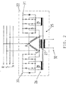
- the output of the generator 3 rests with its 3 phases R, S and T and zero point N on the control element 22, whose structure in the Fig. 2 is shown.
- the control element 22 consists of a three-phase AC transformer 25 whose primary side 26 has three primary windings 27, 28 and 29, of which the primary winding 27 is directly connected to the phases S and T and the other two primary windings 28 and 29 via an electronic Transducers 30 and 31 are connected to the phases S and R and T and R, so that the three primary windings share a secondary AC output 32 in common.
- the converter 30 connected between the phases S and R is bidirectional and the converter 31 connected between the phases R and T is switched unidirectionally.
- the primary winding 27, which lies between the phases S and T, converts the attributable to the first phase S power component according to the applied current directly, ie to 100%, while the transducers 30 and 31, the potential on the other phases linenariwel potential in the feed in the first phase.
- buffer capacitors and electronic switches can be distributed over a pulse width modulation means of the central logic on one phase up to 300% of the rated power and on the other phases different power components up to no power, ie the symmetrically generated three-phase current can in far Limits are unbalanced load.
- the AC output 32 of the control element 22 is connected to a rectifier / inverter unit 33, on the one hand converts the output from the control element 22 AC to DC for charging the battery memory 24 and on the other hand, the DC from the battery memory 24 when requested via the central logic 21 in AC for electrical consumers converts back.
- the consumption of electrical energy is permanently measured by electric meter 34 and transmitted via a connecting line 35 to the central logic 21 for processing.
- 34 four-quadrant counters can be used as the electric meter, with which it is possible to measure all electrical variables such as the reactive current.
- Fig. 3a and 3b show typical according to the VDI guideline 4655 certain daily course for the heat energy and electrical energy of a single family house.
- the annual duration lines and the daily heat and power curves are stored in the central logic 21 and are continuously updated in accordance with the actual consumption via the recorded measured values.
Abstract
Die Erfindung betrifft ein Verfahren und eine Vorrichtung zum Betreiben eines Blockheizkraftwerkes, insbesondere Mini/Mikro-BHKW, für ein Einfamilienhaus. Die Aufgabe der Erfindung besteht darin, ein Verfahren und eine Vorrichtung zum Betreiben eines Mini/Mikro-Blockheizkraftwerkes für Einfamilienhäuser bereitzustellen, mit denen die jährliche Laufzeit des Mini/Mikro-BHKW bei gleichzeitiger Verbesserung des thermischen und elektrischen Wirkungsgrades deutlich reduziert und der Wartungsaufwand sowie die Betriebskosten gesenkt werden. Gelöst wird diese Aufgabe dadurch, dass die auf den einzelnen Phasen (R, S und T) vorzuhaltende elektrische Leistung des Generators (3) in Abhängigkeit der momentan anliegenden Verbrauchslast aus Wärmeenergie und Elektroenergie zumindest von einer Phase (R und T) teilweise oder insgesamt auf die dritte Phase (S) umverteilt und so an die momentan anliegende Last aus Wärme- und Elektroenergie angepasst wird, in dem die momentanen Lasten aus Wärmeenergie und Elektroenergie permanent gemessen, die Messwerte an die Zentrallogik (21 übermittelt, in dieser mit einer auf den Verbrauch abgestimmten Jahresdauer- und Tagesgariglinie für Wärme- und Elektroenergie verglichen, Lastabweichungen mit zulässiger Toleranz festgestellt und die in einer oder beiden Phasen (R, T) vorgehaltene elektrische Leistung durch ein Regelglied (22) entsprechend der momentanen Verbrauchslast auf die dritte Phase (S) potenzialfrei eingespeist wird.The invention relates to a method and a device for operating a combined heat and power plant, in particular mini / micro CHP, for a detached house. The object of the invention is to provide a method and apparatus for operating a mini / micro combined heat and power plant for single-family homes, with which the annual life of the mini / micro CHP while improving the thermal and electrical efficiency significantly reduced and the maintenance and the Operating costs are lowered. This object is achieved in that the electrical power of the generator (3) to be maintained at the individual phases (R, S and T) depends in part or in total on at least one phase (R and T) as a function of the currently applied consumption load of heat energy and electrical energy the third phase (S) is redistributed and adapted to the currently applied load of heat and electricity, in which the instantaneous loads of thermal energy and electric energy permanently measured, the measured values to the central logic (21 transmitted, in this with a consumption matched continuous annual and Tagesgariglinie for heat and electricity, determined load deviations with allowable tolerance and held in one or both phases (R, T) electrical power by a control element (22) according to the current load on the third phase (S) potential-free is fed.
Description
Die Erfindung betrifft ein Verfahren zum Betreiben eines Mini/Mikro-Blockheizkraftwerkes für ein Einfamilienhaus, bei dem ein Verbrennungsmotor ein Drehmoment zum Antrieb einer als Generator eingesetzten Asynchronmaschine, die einen Drehstrom mit den Phasen R, S und T zur Entnahme einer elektrische Leistung zwecks Erzeugen von Wärme- und Elektroenergie für die Verbraucher im Haus liefert, und einen Abgasstrom erzeugt, dessen Abwärme über einen Wärmetauscher einem Wärmespeicher zum Erzeugen von Wärmeenergie für den Brauchwasser- und Heizkreislauf und von Warmwasser des Hauses zugeführt wird, ein Batteriespeicher zum Vorhalten von elektrischer Leistung für elektrische Verbraucher und eine Gleichrichter/Wechselrichter-Einheit zum Aufladen des Batteriespeichers durch Gleichrichten zumindest eines Teils des vom Generator gelieferten Wechselstroms und zum Umwandeln des Gleichstroms in Wechselstrom für elektrische Verbraucher im Haus, wobei der Verbrennungsmotor, der Generator, der Wärmespeicher, der Batteriespeicher und die Gleichrichter/Wechselrichter-Einheit von einer Zentrallogik gesteuert werden.The invention relates to a method for operating a mini / micro combined heat and power plant for a family house, in which an internal combustion engine, a torque for driving an asynchronous induction generator, which uses a three-phase current with the phases R, S and T for the purpose of generating Provides heat and electricity for consumers in the house, and generates a waste gas stream, the waste heat is supplied via a heat exchanger to a heat storage for generating heat energy for the domestic water and heating circuit and hot water of the house, a battery storage for holding electrical power for electrical A load and a rectifier / inverter unit for charging the battery storage by rectifying at least a portion of the alternating current supplied by the generator and converting the direct current into alternating current for electrical consumers in the house, wherein the Internal combustion engine, the generator, the heat accumulator, the battery storage and the rectifier / inverter unit are controlled by a central logic.
Die Erfindung betrifft weiterhin Vorrichtungen zur Durchführung des Verfahrens mit einem Verbrennungsmotor, der ein Drehmoment zum Antrieb einer als Generator eingesetzten Asynchronmaschine, die Drehstrom mit den Phasen R, S und T zur Entnahme einer elektrische Leistung für den Wärme- und Elektroenergieverbrauch im Haus liefert, und einen Abgasstrom erzeugt, dessen Abwärme über einen Wärmetauscher einem Wärmespeicher zum Erzeugen von Wärmeenergie für den Brauchwasser- und Heizkreislauf und Warmwasser des Hauses zugeführt wird, einem Batteriespeicher zum Vorhalten von elektrischer Leistung für elektrische Verbraucher, einer Gleichrichter/Wechselrichter-Einheit zum Aufladen des Batteriespeichers durch Gleichrichten zumindest eines Teils des vom Generator gelieferten Wechselstroms und zum Umwandeln des Gleichstroms in Wechselstrom für elektrische Verbraucher im Haus und einer Zentrallogik, die mit dem Verbrennungsmotor, Generator, Wärmespeicher, Batteriespeicher und der Gleichrichter/Wechselrichter-Einheit zum Ansteuern verbunden ist.The invention further relates to devices for carrying out the method with an internal combustion engine, which supplies a torque for driving an asynchronous machine used as a generator, the three-phase current with the phases R, S and T for the removal of electrical power for the heat and electrical energy consumption in the house, and generates a waste gas stream, the waste heat is supplied via a heat exchanger to a heat storage for generating heat energy for the domestic water and heating circuit and hot water of the house, a battery storage for holding electrical power for electrical loads, a rectifier / inverter unit for charging the battery storage by Rectifying at least a portion of the alternating current supplied by the generator and converting the direct current into alternating current for household electrical appliances and central logic associated with the internal combustion engine, generator, heat accumulator, battery storage and the same Inverter / inverter unit is connected for driving.
Blockheizkraftwerke (BHKW) stellen grundsätzlich Wärme- und Elektroenergie aus der Kraft-Wärme-Kopplung zur Verfügung, bei der ein mit Öl oder Gas angetriebener Verbrennungsmotor bzw. eine Brennstoffzelle mit einem Strom erzeugenden Generator gekoppelt ist (
Blockheizkraftwerke kommen immer dort zum Einsatz, wo neben der Elektroenergie auch Wärmenergie genutzt werden kann. Wichtige Einsatzgebiete für Blockheizkraftwerke sind deshalb Wohnsiedlungen, Gewerbebetriebe, Gewerbeparks, öffentliche Gebäude oder Schwimmbäder. Diese Blockheizkraftwerke sind für lange Laufzeiten unter Volllast konzipiert und arbeiten entweder in einer wärmegeführten oder stromgeführten Betriebsweise. Bei der wärmegeführten Betriebsweise ist die Steuergröße des BHKW der Wärmebedarf und bei der stromgeführten Betriebsweise der Strom. Voraussetzung für eine wirtschaftliche Betriebsweise des BHKW ist eine weitgehend unterbrechungsfreie Laufzeit von mindestens 6000 Stunden pro Jahr (
Des Weiteren ist bekannt, in Mehrfamilienhäusern Mini-Blockheizkraftwerke mit Leistungen kleiner 50 kW und in Einfamilienhäuser sogenannte Mikro-Blockheizkraftwerke mit Leistungen kleiner 20kW einzusetzen, die jedoch auch eine Mindestlaufzeit von >5000 Stunden pro Jahr und zudem einen Zusatzkessel oder einen Pufferspeicher erfordern ("
Aus der
Des Weiteren offenbart die
Außerdem ist ein Asysnchrongenerator bekannt, der ein einphasiges Verbrauchernetz über eine Transformation versorgt, indem die dreiphasig symmetrisch erzeugte Energie vollständig für den einphasigen Anschluss umgewandelt wird (
Allen diesen bekannten Lösungen ist der Nachteil gemeinsam, dass die elektrische Leistung des Generators nicht an die momentane Verbrauchslast aus Wärme- und Elektroenergie anpassbar ist.Furthermore, it is known to use mini-combined heat and power plants with capacities less than 50 kW in single-family houses and so-called micro-cogeneration plants with capacities of less than 20 kW, which, however, also require a minimum running time of> 5000 hours per year and also an additional boiler or a buffer tank ("
From the
Furthermore, the
In addition, an Asysnchrongenerator is known, the one-phase consumer network via a transformation by converting the three-phase symmetrically generated energy completely for the single-phase connection (
All these known solutions have the common disadvantage that the electric power of the generator is not adaptable to the current consumption load from heat and electrical energy.
Bei diesem Stand der Technik liegt der Erfindung die Aufgabe zugrunde, ein Verfahren und eine Vorrichtung zum Betreiben eines Mini/Mikro-Blockheizkraftwerkes für Einfamilienhäuser bereitzustellen, mit denen die jährliche Laufzeit des Mini/Mikro-BHKW bei gleichzeitiger Verbesserung des thermischen und elektrischen Wirkungsgrades deutlich reduziert und der Wartungsaufwand sowie die Betriebskosten gesenkt werden.In this prior art, the present invention seeks to provide a method and apparatus for operating a mini / micro combined heat and power plant for single-family homes, which significantly reduces the annual life of the mini / micro CHP while improving the thermal and electrical efficiency and the maintenance and operating costs are reduced.
Diese Aufgabe wird durch ein Verfahren der eingangs genannten Art mit den Merkmalen des Anspruches 1 und durch die Vorrichtungen mit den Merkmalen der Ansprüche 10 oder 11 gelöst.This object is achieved by a method of the type mentioned above with the features of claim 1 and by the devices with the features of
Vorteilhafte Ausgestaltungen des erfindungsgemäßen Verfahrens und der Vorrichtungen sind den Unteransprüchen entnehmbar.Advantageous embodiments of the method and the devices according to the invention can be taken from the subclaims.
Die erfindungsgemäße Lösung geht von dem Kerngedanken aus, die vom Generator abgegebene Leistung in Abhängigkeit der momentanen Gesamtlast der Verbraucher im Einfamilienhaus umzuverteilen und zugleich an die entsprechenden momentanen Teillasten aus thermischer Energie und Elektroenergie synchron anzupassen.
Dies wird dadurch erreicht, dass die auf den einzelnen Phasen R, S und T vorzuhaltende elektrische Leistung des Generators in Abhängigkeit der momentan anliegenden Verbrauchslast aus Wärmeenergie und Elektroenergie zumindest von einer Phase R und T teilweise oder insgesamt zumindest auf die dritte Phase S umverteilt und so an die momentan anliegende Last aus Wärme- und Elektroenergie angepasst wird, in dem die momentanen Lasten aus Wärmeenergie und Elektroenergie gemessen, die Messwerte an die Zentrallogik übermittelt, in dieser mit einer auf den Verbrauch abgestimmten Jahresdauer- und Tagesganglinie für Wärme- und Elektroenergie verglichen, Lastabweichungen mit zulässiger Toleranz festgestellt und die in einer oder beiden Phasen vorgehaltene elektrische Leistung über ein Regelglied entsprechend der momentanen Verbrauchslast auf die dritte Phase S potenzialfrei eingespeist wird.The solution according to the invention is based on the Core ideas to redistribute the power output from the generator depending on the current total load of consumers in a family house and at the same time to synchronize the corresponding momentary partial loads of thermal energy and electricity synchronously.
This is achieved by virtue of the fact that the electric power of the generator to be maintained at the individual phases R, S and T is at least partially or altogether redistributed at least to the third phase S as a function of the currently applied consumption load of heat energy and electrical energy, and so on adapted to the momentary load of heat and electricity, in which the instantaneous loads of thermal energy and electric energy are measured, the measured values transmitted to the central logic, compared in this with an annual and daily temperature curve for heat and electric energy adapted to the consumption, Load deviations detected with allowable tolerance and held in one or both phases electrical power via a control element according to the current load on the third phase S is fed potential free.
In einer bevorzugten Ausführungsvariante wird das erfindungsgemäße Verfahren durch folgende Schritte ausgeführt:
- a) Starten des Verbrennungsmotors und Zuschalten des Generators zum Erzeugen eines symmetrischen Drehstroms mit den Phasen R, S und T,
- b) stetiges Messen der Verbrauchslast durch die am Wärmespeicher zugeordnete Wärmemesser und den Elektroverbrauchern zugeordnete Elektrozähler,
- c) Ablegen einer auf das Einfamilienhaus berechneten Jahresdauer- und Tagesganglinie für die Wärmeenergie und für die Elektroenergie und deren permanente Fortschreibung entsprechend dem tatsächlichen Verbrauch in der Zentrallogik,
- d) Ermitteln der momentanen Lasten aus den Messwerten und Bestimmen der Lastabweichungen von der Tagesganglinie für die Wärme- und Elektroenergie durch die Zentrallogik,
- e) direktes Umwandeln des auf eine erste Phase (S) des Drehstroms entfallenden Leistungsanteils durch den anliegenden Strom und Wandeln der auf die anderen beiden Phasen des Drehstroms entfallenden Leistungsanteile durch das Regelglied,
- f) Verteilen der Leistungsanteile der Phasen R und T auf die Phase S durch das Regelglied derart, dass sie der momentan ermittelten Last aus Wärme- und Elektroenergie gemäß Schritt d) entsprechen,
- g) Laden des Batteriespeichers und Wärmespeichers derart, dass der auf den Batteriespeicher entfallende Leistungsanteil den auf den Wärmespeicher entfallenden Leistungsanteil um 5 bis 10% übersteigt,
- h) Abschalten des Verbrennungsmotors, sobald der Batteriespeicher und Wärmespeicher ihre maximal vorgegebenen Kapazitäten an Leistungsanteilen erreichen,
- i) Entnehmen der Leistungsanteile aus dem Batteriespeicher und Wärmespeicher durch die Verbraucher bis auf eine Restkapazität an Leistungsanteilen von mindestens 4% und
- j) Zuschalten des Verbrennungsmotors, sobald der Batteriespeicher und Wärmespeicher die Restkapazität gemäß Schritt i) unterschreitet und erneutes Ausführen der Schritte a) bis j).
- a) Starting the internal combustion engine and connecting the generator for generating a symmetrical three-phase current with the phases R, S and T,
- b) continuous measurement of the consumption load by the heat meter associated with the heat accumulator and the electrical consumers associated electrical meter,
- c) Deposit of a calculated on the family house Annual and daily cycle for the heat energy and for the electric energy and their permanent updating according to the actual consumption in the central logic,
- d) Determining the instantaneous loads from the measured values and determining the load deviations from the daily curve for the heat and electrical energy through the central logic,
- e) directly converting the power component attributable to a first phase (S) of the three-phase current through the applied current and converting the power components attributable to the other two phases of the three-phase current through the control element,
- f) distributing the power components of the phases R and T to the phase S by the control element such that they correspond to the currently determined load of heat and electric energy according to step d),
- g) charging the battery storage and heat accumulator such that the power component attributable to the battery storage exceeds the power component attributable to the heat accumulator by 5 to 10%,
- h) switching off the internal combustion engine as soon as the battery storage and heat storage reach their maximum predetermined capacities of power components,
- i) taking the power components from the battery storage and heat storage by the consumer up to a residual capacity of at least 4% and
- j) connecting the internal combustion engine, as soon as the battery storage and heat storage below the residual capacity according to step i) and re-executing the steps a) to j).
In einer weiteren bevorzugten Ausführungsform des erfindungsgemäßen Verfahrens ist vorgesehen, dass als Regelglied ein Drehstrom-Wechselstrom-Transformator mit □Wandler verwendet wird, wobei der Drehstrom-Wechselstrom-Transformator den auf eine Phase entfallende Leistungsanteil durch den direkt anliegenden Strom umwandelt und die Wandler die auf die anderen Phasen entfallende Leistungsanteile potenzialfrei in die erste Phase einspeisen. Dies hat den Vorteil, dass die Leistung in jeder Phase an die Last angepasst werden kann und nur soweit vorgehalten werden muss, wie sie gebraucht wird.In a further preferred embodiment of the method according to the invention it is provided that as Regulator is a three-phase AC transformer with □ converter is used, the three-phase AC transformer transforms the attributable to one phase power component by the directly applied current and the converter feed the attributable to the other phases power components potential-free in the first phase. This has the advantage that the power in each phase can be adapted to the load and only needs to be kept as far as it is needed.
Nach einer weiteren bevorzugten Ausgestaltung des erfindungsgemäßen Verfahrens wird der Wandler für die Phase R und der Wandler für die Phase T durch die Schaltung von Gleichrichtern so betrieben, dass ein Wandler unidirektional und der andere Wandler bidirektional geschaltet ist.
Zweckmäßigerweise können der Drehstrom-Wechselstrom-Transformator und die Wandler in die Schaltung des Generators integriert werden und direkt aus diesem betrieben werden.According to a further preferred embodiment of the method according to the invention, the converter for the phase R and the converter for the phase T is operated by the circuit of rectifiers so that a converter is unidirectional and the other converter is bidirectional.
Conveniently, the three-phase AC transformer and the converter can be integrated into the circuit of the generator and operated directly from this.
In einer alternativen Ausführungsform des erfindungsgemäßen Verfahrens können als Regelglied für jede einzelne Phase von der Zentrallogik gesteuerte Gleichrichter verwendet werden, die dafür Sorge tragen, dass die Leistung an die jeweilige Last in den einzelnen Zweigen angepasst wird.In an alternative embodiment of the method according to the invention can be used as a control element for each phase controlled by the central logic rectifier, which ensure that the power is adapted to the respective load in the individual branches.
Nach einer weiteren bevorzugten Ausgestaltung des erfindungsgemäßen Verfahrens werden als Elektrozähler Vier-Quadranten-Zähler eingesetzt, die die momentane Verbrauchslast an Elektroenergie in jeder Phase messen und die Messwerte an die Zentrallogik zur Verarbeitung und Ausgabe von Steuerbefehlen übermitteln.According to a further preferred embodiment of the method according to the invention, four-quadrant counters which measure the instantaneous consumption load of electrical energy in each phase and transmit the measured values to the central logic for processing and outputting control commands are used as electrical meters.
Die Aufgabe wird weiterhin durch eine Vorrichtung der eingangs genannten Art dadurch gelöst, dass zum Ermitteln der momentanen Last von Wärme- und Elektroenergie Wärmemesser und Elektrozähler sowie zum Anpassen der vorzuhaltenden elektrischen Leistung der einzelnen Phasen R, S und T des Drehstroms an die momentane Last an Wärme- und Elektroenergie ein Drehstrom-Wechselstrom-Transformator mit elektronischen Wandlern vorgesehen sind, dessen Primärseite drei, einem sekundären Ausgang zugeordnete Primärwicklungen aufweist, von denen eine der Primärwicklungen direkt mit den Phasen S und T sowie die anderen Primärwicklungen über je einen elektronischen Wandler mit den Phasen S und R und R und T verbunden sind.
Alternativ kann anstelle des Drehstrom-Wechselstrom-Transformators mit elektronischen Wandlern an jeder Phase als Regelglied ein von der Zentrallogik angesteuerter diodengeregelter Gleichrichter verwendet werden.The object is further achieved by a device of the type mentioned in that for determining the instantaneous load of heat and electricity heat meter and electric meter and to adjust the vorzuhaltenden electrical power of the individual phases R, S and T of the three-phase current to the instantaneous load Heat and electric power, a three-phase AC transformer with electronic transducers are provided, the primary side has three, a secondary output associated primary windings, of which one of the primary windings directly to the phases S and T and the other primary windings via an electronic converter with the Phases S and R and R and T are connected.
Alternatively, instead of the three-phase AC transformer with electronic transducers at each phase, a diode-controlled rectifier controlled by the central logic can be used as the control element.
In einer weiteren zweckmäßigen Ausführungsform der Erfindung weist der den Phasen R und S zugeordnete Wandler bidirektional und der den Phasen R und T zugeordnete Wandler unidirektional geschaltete Gleichrichterdioden auf die mit der Zentrallogik zwecks Ansteuerung verbunden sind.In a further expedient embodiment of the invention, the converter assigned to the phases R and S is bidirectional and the rectifier diodes connected to the phases R and T are connected in unidirectional manner to the central logic for the purpose of control.
Eine weitere vorteilhafte Ausgestaltung der erfindungsgemäßen Vorrichtung sieht vor, dass der Drehstrom-Wechselstrom-Transformator und die Wandler in die Schaltung des Generators integriert sind.A further advantageous embodiment of the device according to the invention provides that the three-phase AC transformer and the converter are integrated into the circuit of the generator.
Zweckmäßig ist weiterhin, dass die Wärmemesser dem Wärmespeicher und die Elektrozähler der Hausverteilung zugeordnet sind, wobei die Wärmemesser und der Elektrozähler mit der Zentrallogik verbunden sind.It is also expedient that the heat meter are assigned to the heat storage and the electricity meter of the house distribution, the heat meter and the electric meter connected to the central logic.
Als besonders geeignet für die Messung des momentanen Verbrauchs an Elektroenergie haben sich Vier-Quadranten-Zähler erwiesen.Four-quadrant counters have proven particularly suitable for measuring the instantaneous consumption of electrical energy.
Weitere Vorteile und Einzelheiten ergeben sich aus der nachfolgenden Beschreibung unter Bezugnahme auf die beigefügten Zeichnungen.Further advantages and details will become apparent from the following description with reference to the accompanying drawings.
Die Erfindung soll nachstehend an einem Ausführungsbeispiel näher erläutert werden.The invention will be explained in more detail below using an exemplary embodiment.
-
Fig. 1 eine schematische Darstellung des Mini/Mikro-Blockheizkraftwerks als Insel-Lösung mit Anschluss an die Heizung, Warmwasserversorgung und Elektroverbraucher,Fig. 1 a schematic representation of the mini / micro combined heat and power plant as island solution with connection to the heating, hot water supply and electrical consumers, -
Fig. 2 eine in den Generator integrierte Schaltung des Drehstrom-Wechselstrom-Transformator mit Wandlern und Wechselstromausgang undFig. 2 an integrated into the generator circuit of the three-phase AC transformer with converters and AC output and -
Fig. 3a und 3b eine Darstellung einer typischen Tagesganglinie der Wärmelast und Stromlast eines EinfamilienhausesFig. 3a and 3b a representation of a typical daily graph of the heat load and electricity load of a detached house
Die
Energieverbrauch von 6 kWh elektrischer und 20 kWh thermischer Leistung versorgt. Das Mini/Mikro-Blockheizkraftwerk (BHKW) 1 umfasst im Wesentlichen einen mit Öl oder Gas betriebenen flüssigkeitsgekühlten Verbrennungsmotor 2 und eine Asynchronmaschine als Generator 3, der mit dem Verbrennungsmotor 2 gekoppelt ist.
Der Verbrennungsmotor 2 hat eine mechanische Ausgangsleistung von 10 kW und ist mit einer Zuführleitung 38 für Öl oder Gas verbunden. Die Asynchronmaschine liefert in einer Vierleiter-Schaltung einen symmetrischen Drehstrom mit den Phasen R, S und T bei 50 Hz 400/231 V und einer Ausgangsleistung bis zu 20 kW, wobei zwischen den drei Phasen eine unsymmetrische Belastung, beispielsweise auf der einen Phase 300% der Nennleistung und auf den anderen beiden Phasen keine Leistung einstellbar sein muss.Energy consumption of 6 kWh electrical and 20 kWh thermal power supplied. The mini / micro cogeneration unit (CHP) 1 essentially comprises a liquid-cooled
The
Die Verbrennungsabgase des Verbrennungsmotors 2 werden einem Abgas-Wärmetauscher 4 zugeführt, dessen Flüssigkeitsseite über eine durch ein Rückschlagventil 5 absperrbare Rohrleitung 6 mit einem Wärmespeicher 7 verbunden ist, der mit Brauchwasser gefüllt ist. Die abgekühlten Verbrennungsabgase werden von der Gasseite des Abgas-Wärmetauschers 4 über eine Abgasleitung 8 nach außen in die Atmosphäre abgeführt. Der Wärmespeicher 7 hat ein Speichervolumen 1000 1 und ist als Schichtenspeicher ausgeführt.
Der Kühlwasserkreislauf des Verbrennungsmotors 2 steht durch eine Rohrleitung 9 mit dem Wärmespeicher 7 in Verbindung, so dass einerseits die Motorwärme und andererseits die Verbrennungsabgase jeweils ihre Wärme an das Brauchwasser im Wärmespeicher 7 abgeben können.
Die Rohrleitung 9 ist mit der Rohrleitung 6 über eine Verbindungsleitung 10 verbunden, die mittels eines Drei-WegeVentils 11 absperrbar ist, so dass der Kühlkreislauf des Verbrennungsmotors 2 zu Wartungs- und Montagezwecken unterbrochen werden kann.The combustion exhaust gases of the
The cooling water circuit of the
The pipe 9 is connected to the
Der Wärmespeicher 7 ist durch Vorlaufleitungen 12 und Rücklaufleitungen 13 mit den Heizkörpern 14 bzw. der Fußbodenheizung 15 des Hauses verbunden.
Die Steuerung der Heizung erfolgt über eine übliche Heizungssteuerung 37, die daher nicht weiter beschrieben werden muss.
Im Wärmespeicher 7 befindet sich ein Wärmeaustauscher 16, der mit einer Kaltwasserzuleitung 17 verbunden ist, über die Kaltwasser dem Wärmeaustauscher 16 zugeführt, durch das Brauchwasser erwärmt und an die Verbrauchsstellen im Haus zu Entnahme verteilt wird.
Zusätzlich ist der Wärmespeicher 7 mit einem elektrischen Heizstab 18 ausgerüstet, der durch einen von der Zentrallogik 21 angesteuerten elektronischen Schalter 36 zuschaltbar ist, wenn die vom Brauchwasser bereitgestellte Wärmemenge zum Erwärmen der Heizung und Warmwasser nicht ausreichen sollte.The
The control of the heating via a
In the
In addition, the
Am Wärmespeicher 7 befinden sich Wärmemesser 19, die der zum Wärmetauscher 4 führenden Rohrleitung 6 und der mit dem Kühlkreislauf des Verbrennungsmotors 2 in Verbindung stehenden Rohrleitung 9 zugeordnet sind. Die Wärmemesser 19 messen permanent die verbrauchten Wärmemengen und übermitteln diese über die Steuerleitungen 20 an die Zentrallogik 21, die die Messwerte verarbeitet und in entsprechende Steuerbefehle für ein später noch beschreibendes Regelglied 22 am Generator 3 umsetzt.At the
Die Zentrallogik 21 ist weiterhin mit dem Verbrennuhgsmotorotor 2, dem Generator 3 und dem Heizstab 18 über Steuerleitungen 23 verbunden, die die Steuerbefehle der Zentrallogik 21 zum Starten und Stoppen des Verbrennungsmotors 2, Anfahren und Ausschalten des Generators 3 sowie Zu- und Ausschalten des Heizstabes 18 weiterleitet.The
Zum Mini/Mikro-BHKW 1 gehört des Weiteren ein Batteriespeicher 24, welcher sich aus 8 bis 12 Lithium-Ionen- oder Blei-Batterien mit einer Kapazität von 150 bis 225Ah zusammensetzt. Der Ausgang des Generators 3 liegt mit seinen 3 Phasen R, S und T sowie Nullpunkt N am Regelglied 22 an, dessen Aufbau in der
Das Regelglied 22 besteht aus einem Drehstrom-Wechselstrom-Transformator 25, dessen Primärseite 26 drei Primärwicklungen 27, 28 und 29 aufweist, von denen die Primärwicklung 27 direkt mit den Phasen S und T verbunden sowie die anderen beiden Primärwicklungen 28 und 29 über je einen elektronischen Wandler 30 und 31 an die Phasen S und R sowie T und R angeschlossen sind, so dass sich die drei Primärwicklungen gemeinsam einen sekundären Wechselstromausgang 32 teilen.
Der zwischen den Phasen S und R angeschlossene Wandler 30 ist bidirektional und der zwischen die Phasen R und T angeschlossene Wandler 31 ist unidirektional geschaltet. Die Primärwicklung 27, die zwischen den Phasen S und T liegt, wandelt den auf die erste Phase S entfallenden Leistungsanteil entsprechend dem anliegenden Strom direkt um, d.h. zu 100%, während die Wandler 30 und 31 die auf den anderen Phasen entfallenden Leistungsariteile potenzialfrei in die erste Phase einspeisen. Durch die Ansteuerung der in den Wandlern 30 und 31 geschalteten Gleichrichter, Pufferkapazitäten und elektronische Schalter können über eine Pulsweitenmodulation mittels der Zentrallogik auf der einen Phase bis zu 300% der Nennleistung und auf den anderen Phasen unterschiedliche Leistungsanteile bis zu keiner Leistung verteilt werden, d.h. der symmetrisch erzeugte Drehstrom kann in weiten Grenzen unsymmetrisch belastet werden.The mini / micro CHP 1 further includes a
The
The
Es wird nochmals auf die
Es soll nun der Ablauf des erfindungsgemäßen Verfahrens näher verdeutlicht werden.
Das erfindungsgemäße Verfahren läuft wie folgt ab:
- a) Starten des
Verbrennungsmotors 2 und Zuschalten desGenerators 3 zum Erzeugen eines Drehstroms mit den Phasen R, S und T, - b) stetiges Messen der Verbrauchslast durch die
dem Wärmespeicher 7zugeordnete Wärmemesser 19 und denElektroverbrauchern zugeordnete Elektrozähler 34, - c) Ablegen einer auf das Einfamilienhaus berechneten Jahresdauer- und Tagesganglinie für die Wärmeenergie und für die Elektroenergie und deren permanente Fortschreibung entsprechend dem tatsächlichen Verbrauch in
der Zentrallogik 21, - d) Ermitteln der momentanen Teillasten für die Wärme- und Elektroenergie aus den Messwerten und Bestimmen der Lastabweichungen von der Tagesganglinie durch die
Zentrallogik 21, - e) Umwandeln des auf eine erste Phase des Drehstroms entfallenden Leisaungsanteils und Wandeln der auf die anderen beiden Phasen des Drehstroms entfallenden Leistungsanteile durch
das Regelglied 22, - f) Verteilen der Leistungsanteile auf die Phasen R, S und T
durch das Regelglied 22 derart, dass sie der momentan ermittelten Last aus Wärme- und Elektroenergie gemäß Schritt d) entsprechen, - g) Laden des
Batteriespeichers 24 und Wärmespeichers 7 derart, dass der auf den Batteriespeicher entfallende Leistungsanteil den aufden Wärmespeicher 7 entfallenden Leistungsanteil um 5bis 10% übersteigt, - h) Abschalten des
Verbrennungsmotors 2, sobald der Batteriespeicher 24 und Wärmespeicher 7 ihre maximal vorgegebenen Kapazitäten an Leistungsanteilen erreichen, - i) Entnehmen der Leistungsanteile aus
dem Batteriespeicher 24 und Wärmespeicher 7 durch die Verbraucher bis auf eine Restkapazität an Leistungsanteilen von mindestens 4% und - j) Zuschalten des
Verbrennungsmotors 2, sobald der Batteriespeicher 24 und Wärmespeicher 7 die Restkapazität gemäß Schritt i) unterschreitet und erneutes Ausführen der Schritte a) bis i).
The process according to the invention proceeds as follows:
- a) starting the
internal combustion engine 2 and connecting thegenerator 3 to generate a three-phase current with the phases R, S and T, - b) continuous measurement of the consumption load by the
heat accumulator 7 associatedheat meter 19 and the Electric meters associated withelectric consumers 34, - c) storage of a calculated for the family house periode and daily cycle for the heat energy and for the electric energy and their permanent updating according to the actual consumption in the
central logic 21, - d) determining the instantaneous partial loads for the heat and electric energy from the measured values and determining the load deviations from the diurnal line through the
central logic 21, - e) converting the power fraction attributable to a first phase of the three-phase current and converting the power components attributable to the other two phases of the three-phase current through the
control element 22, - f) distributing the power components to the phases R, S and T by the
control element 22 in such a way that they correspond to the currently determined load of heat and electric energy according to step d), - g) charging the
battery store 24 andheat accumulator 7 such that the power component attributable to the battery store exceeds the power portion attributable to theheat accumulator 7 by 5 to 10%, - h) switching off the
internal combustion engine 2 as soon as thebattery storage 24 andheat storage 7 reach their maximum predetermined capacities of power components, - i) removing the power components from the
battery storage 24 andheat storage 7 by the consumers except for a residual capacity of at least 4% and - j) connecting the
internal combustion engine 2, as soon as thebattery storage 24 andheat storage 7, the remaining capacity according to step i) below and re-executing steps a) to i).
Die
Sobald eine Abweichung der durch die Wärmemesser 19 und die Elektrozähler 34, beispielsweise Vier-Quadranten-Zähler, momentan gemessenen Last von der Tagesganglinie für Wärmeenergie und für Elektroenergie in Abhängigkeit der Dauerlinie durch die Zentrallogik 21 festgestellt wird, gibt diese einen Regelbefehl an das Regelglied 22 aus, das eine an die Abweichung angepasste Umverteilung der auf die beiden Phasen R und und T entfallenden Leistungsanteile entsprechend der momentan anliegenden tatsächlichen Leistung an Wärme- und Elektroenergie vornimmt, ohne die auf der ersten Phase S anliegenden Last zu verändern.As soon as a deviation of the momentary measured by the
Die Erfindung zeigt eine ganze Reihe von Vorteilen gegenüber dem Stand der Technik:
- 1. Sie ist besonders für Einfamilienhäuser geeignet.
- 2. Die diskontinuierliche Fahrweise des BHKW stellt auch maximal unterschiedliche Verbräuche von thermischer und elektrischer Energie sicher.
- 3. Die erfindungsgemäße diskontinuierliche Fahrweise des Mini/Mikro-BHKW ermöglicht im Wesentlichen eine längere Lebensdauer des BHKW und zwar um das Vierbzw. Fünffache.
- 4. Die mit erheblichen Kosten verbundenen Wartungszyklen verkürzen sich infolge der Umverteilung der bereitstehenden Leistung auf die jeweilige momentane Last.
- 5. Es wird trotz der diskontinuierlichen Fahrweise ein effektiver Wirkungsgrad von >90% erreicht.
- 6. Die Kosten reduzieren sich für Nutzer um 30 bis 40%.
- 7. Witterungsunbilden mit den bekannten Folgen von Stromausfällen und sonstige Unsicherheiten haben auf die Mini/Mikro-BHKW nach der Erfindung keinen Einfluss, weil es autark seine Energie erzeugt.
- 8. Die erfindungsgemäßen Mini/Mikro-BHKW kann optional an das öffentliche Stromversorgungsnetz angeschlossen werden und ist somit flexibel einsetzbar.
- 1. It is particularly suitable for single-family homes.
- 2. The discontinuous mode of operation of the CHP also ensures maximum different consumption of thermal and electrical energy.
- 3. The discontinuous mode of operation of the mini / micro CHP according to the invention essentially allows a longer life of the CHP and that by the Vierbzw. Fivefold.
- 4. The maintenance costs associated with considerable costs are reduced as a result of the redistribution of the available power to the respective instantaneous load.
- 5. An effective efficiency of> 90% is achieved despite the discontinuous driving style.
- 6. The costs for users are reduced by 30 to 40%.
- 7. Weather training with the known consequences of power failures and other uncertainties have no influence on the mini / micro CHP according to the invention, because it generates its energy independently.
- 8. The mini / micro CHP according to the invention can optionally be connected to the public power grid and is thus flexible.
- Mini/Mikro-BHKWMini / Micro-CHP
- 11
- Verbrennungsmotorinternal combustion engine
- 22
- Generatorgenerator
- 33
- Abgas-WärmetauscherExhaust gas heat exchanger
- 44
- Rückschlagventilcheck valve
- 55
- Rohrleitungpipeline
- 66
- Wärmespeicherheat storage
- 77
- Abgasleitungexhaust pipe
- 88th
- Rohrleitungpipeline
- 99
- Verbindungsleitung zwischen 6 und 9Connecting line between 6 and 9
- 1010
- Drei-Wege-VentilThree-way valve
- 1111
- Vorlaufleitungensupply lines
- 1212
- RücklaufleitungenReturn lines
- 1313
- Heizkörperradiator
- 1414
- Fußbodenheizungunderfloor heating
- 1515
- Wärmeaustauscher in 7Heat exchanger in 7
- 1616
- KaltwasserzuleitungCold water supply line
- 1717
- Elektrischer HeizstabElectric heating rod
- 1818
- Wärmemesserthermometer
- 1919
- Steuerleitungen für 19Control cables for 19
- 2020
- ZentrallogikCentral logic
- 2121
- Regelgliedcontrol element
- 2222
- Steuerleitungcontrol line
- 2323
- Batteriespeicherbattery storage
- 2424
- Drehstrom-Wechselstrom-TransformatorThree-phase AC transformer
- 2525
- Primärseite von 25Primary side of 25
- 2626
- Primärwicklungenprimaries
- 27,28,2927,28,29
- Elektronische WandlerElectronic transducers
- 30,3130.31
- Sekundärer WechselstromausgangSecondary AC output
- 3232
- Gleichstrom/WechselrichtereinheitDC / inverter unit
- 3333
- Elektrozählerelectricity meters
- 3434
- Verbindungsleitung für 34Connection line for 34
- 3535
- Elektronischer Schalter für 18Electronic switch for 18
- 3636
- Heizungssteuerungheating control
- 3737
- Zuführleitung für Öl oder GasSupply line for oil or gas
- 3838
- DrehstromphasenRotary current phases
- R, S, TR, S, T
- Null-PunktZero point
- NN
Claims (16)
Applications Claiming Priority (1)
| Application Number | Priority Date | Filing Date | Title |
|---|---|---|---|
| DE102015009086.0A DE102015009086B4 (en) | 2015-07-17 | 2015-07-17 | Method and device for operating a mini / micro combined heat and power plant for single-family homes |
Publications (2)
| Publication Number | Publication Date |
|---|---|
| EP3124878A1 true EP3124878A1 (en) | 2017-02-01 |
| EP3124878B1 EP3124878B1 (en) | 2019-10-23 |
Family
ID=56344951
Family Applications (1)
| Application Number | Title | Priority Date | Filing Date |
|---|---|---|---|
| EP16001341.3A Active EP3124878B1 (en) | 2015-07-17 | 2016-06-14 | Method and device for operating a mini/micro chp plant for single-family dwellings |
Country Status (3)
| Country | Link |
|---|---|
| EP (1) | EP3124878B1 (en) |
| CN (1) | CN106356911B (en) |
| DE (1) | DE102015009086B4 (en) |
Cited By (3)
| Publication number | Priority date | Publication date | Assignee | Title |
|---|---|---|---|---|
| WO2018188678A1 (en) | 2017-04-10 | 2018-10-18 | Ceska Energeticko-Auditorska Spolecnost, S. R. O. | Device for optimizing production, consumption, and storage of electric energy |
| DE202017007549U1 (en) | 2017-02-13 | 2022-08-11 | Norbert Hoffmann | System for energy supply of a building and solid heat storage |
| US11859834B2 (en) | 2020-10-07 | 2024-01-02 | Axiom Energy Group, LLC | Micro-combined heat and power system with exterior generator and heating system compatibility and method of use |
Citations (15)
| Publication number | Priority date | Publication date | Assignee | Title |
|---|---|---|---|---|
| DE4102636C2 (en) | 1991-01-30 | 1994-05-11 | Dieter Creon | Power supply system with an internal combustion engine and a generator |
| DE19740398A1 (en) | 1997-09-09 | 1999-03-11 | Vng Verbundnetz Gas Ag | Combined heat and power facility for energy supply |
| DE19816415A1 (en) | 1998-04-14 | 1999-10-28 | Rainer Mandel | CHP plant |
| DE19822880A1 (en) | 1998-05-22 | 1999-12-02 | Elektra Beckum Ag | Domestic block heating unit for small locations |
| DE202007016024U1 (en) * | 2007-04-02 | 2008-02-21 | Natcon7 Gmbh | Hybrid plant with a biogas plant |
| DE202009009945U1 (en) | 2009-07-20 | 2009-12-03 | Schiegl, Erwin | Mini CHP |
| EP2348597A1 (en) | 2010-01-20 | 2011-07-27 | SMA Solar Technology AG | Equalisation of the partial outputs flowing over the individual phases of a multi-phase alternating current |
| DE102010015702A1 (en) | 2010-04-21 | 2011-10-27 | Volkswagen Ag | Block-type thermal power station i.e. power-heat coupling plant, for providing e.g. electrical power to power consumers in building, has exchangers designed such that exchangers uncouple energy that is guided from burner into exhaust gas |
| DE202011106636U1 (en) | 2011-10-11 | 2011-12-05 | Franz Käsberger | Mini / micro combined heat and power plant for self-sufficient energy supply (electricity and thermal heat utilization) of buildings |
| DE102010043844A1 (en) * | 2010-11-12 | 2012-05-16 | Robert Bosch Gmbh | System for combined heat and power generation, has internal combustion engine and heat storage, where combustion engine is arranged in motor vehicle, and heat storage is arranged in stationary manner |
| DE202011102374U1 (en) | 2011-06-27 | 2012-10-01 | Prosol Invest Deutschland Gmbh | Energy storage and / or supply device |
| DE102011053982A1 (en) * | 2011-09-27 | 2013-03-28 | Lti Drives Gmbh | Generator circuit arrangement for e.g. rotation speed-variable mains supply generator device in wind-power plant, has rectifier and generator-inverter including direct current potentials that are connected together in generator operation |
| DE102011120823A1 (en) | 2011-12-13 | 2013-06-13 | Lichtblick Zuhausekraftwerk Gmbh | Energy storage device for use in e.g. factory, has energy supply network and heater connected with each other, and switching device utilized for regulating and/or controlling electric current in one of electrical connection lines |
| DE102013100999A1 (en) | 2013-01-31 | 2014-07-31 | Philipp Börner | Power supply arrangement has control device that is provided with inverter for providing real power and reactive power, and control unit that is provided for monitoring terminal voltage of electrical energy accumulator |
| DE202010018242U1 (en) | 2009-03-09 | 2014-12-16 | Gerhard Prinz | Power system |
Family Cites Families (1)
| Publication number | Priority date | Publication date | Assignee | Title |
|---|---|---|---|---|
| CN103762609A (en) * | 2014-02-17 | 2014-04-30 | 北海市聚志电子科技有限公司 | Active power regulation and reactive power compensation control system of power distribution network remotely controlled through power frequency communication |
-
2015
- 2015-07-17 DE DE102015009086.0A patent/DE102015009086B4/en active Active
-
2016
- 2016-06-14 EP EP16001341.3A patent/EP3124878B1/en active Active
- 2016-07-15 CN CN201610559942.2A patent/CN106356911B/en active Active
Patent Citations (15)
| Publication number | Priority date | Publication date | Assignee | Title |
|---|---|---|---|---|
| DE4102636C2 (en) | 1991-01-30 | 1994-05-11 | Dieter Creon | Power supply system with an internal combustion engine and a generator |
| DE19740398A1 (en) | 1997-09-09 | 1999-03-11 | Vng Verbundnetz Gas Ag | Combined heat and power facility for energy supply |
| DE19816415A1 (en) | 1998-04-14 | 1999-10-28 | Rainer Mandel | CHP plant |
| DE19822880A1 (en) | 1998-05-22 | 1999-12-02 | Elektra Beckum Ag | Domestic block heating unit for small locations |
| DE202007016024U1 (en) * | 2007-04-02 | 2008-02-21 | Natcon7 Gmbh | Hybrid plant with a biogas plant |
| DE202010018242U1 (en) | 2009-03-09 | 2014-12-16 | Gerhard Prinz | Power system |
| DE202009009945U1 (en) | 2009-07-20 | 2009-12-03 | Schiegl, Erwin | Mini CHP |
| EP2348597A1 (en) | 2010-01-20 | 2011-07-27 | SMA Solar Technology AG | Equalisation of the partial outputs flowing over the individual phases of a multi-phase alternating current |
| DE102010015702A1 (en) | 2010-04-21 | 2011-10-27 | Volkswagen Ag | Block-type thermal power station i.e. power-heat coupling plant, for providing e.g. electrical power to power consumers in building, has exchangers designed such that exchangers uncouple energy that is guided from burner into exhaust gas |
| DE102010043844A1 (en) * | 2010-11-12 | 2012-05-16 | Robert Bosch Gmbh | System for combined heat and power generation, has internal combustion engine and heat storage, where combustion engine is arranged in motor vehicle, and heat storage is arranged in stationary manner |
| DE202011102374U1 (en) | 2011-06-27 | 2012-10-01 | Prosol Invest Deutschland Gmbh | Energy storage and / or supply device |
| DE102011053982A1 (en) * | 2011-09-27 | 2013-03-28 | Lti Drives Gmbh | Generator circuit arrangement for e.g. rotation speed-variable mains supply generator device in wind-power plant, has rectifier and generator-inverter including direct current potentials that are connected together in generator operation |
| DE202011106636U1 (en) | 2011-10-11 | 2011-12-05 | Franz Käsberger | Mini / micro combined heat and power plant for self-sufficient energy supply (electricity and thermal heat utilization) of buildings |
| DE102011120823A1 (en) | 2011-12-13 | 2013-06-13 | Lichtblick Zuhausekraftwerk Gmbh | Energy storage device for use in e.g. factory, has energy supply network and heater connected with each other, and switching device utilized for regulating and/or controlling electric current in one of electrical connection lines |
| DE102013100999A1 (en) | 2013-01-31 | 2014-07-31 | Philipp Börner | Power supply arrangement has control device that is provided with inverter for providing real power and reactive power, and control unit that is provided for monitoring terminal voltage of electrical energy accumulator |
Non-Patent Citations (3)
| Title |
|---|
| "BHKW-Grundlagen, Arbeitsgemeinschaft für sparsamen und umweltfreundlichen Energieverbrauche", ASUE, 2010 |
| "Mini-BHKW -noch zu groß für Ein- und Zweifamilienhäuser", June 2008, SPRINGER |
| T.F.CHAN; L.L. LAI: "Single-Phase Operation of a Three-Phase Induction Generator Using a Novel Line Current Injection Method", IEEE TRANSACTION ON ENERGY CONVERSION, vol. 20, no. 2, 2 June 2005 (2005-06-02) |
Cited By (5)
| Publication number | Priority date | Publication date | Assignee | Title |
|---|---|---|---|---|
| DE202017007549U1 (en) | 2017-02-13 | 2022-08-11 | Norbert Hoffmann | System for energy supply of a building and solid heat storage |
| WO2018188678A1 (en) | 2017-04-10 | 2018-10-18 | Ceska Energeticko-Auditorska Spolecnost, S. R. O. | Device for optimizing production, consumption, and storage of electric energy |
| EP3596797A4 (en) * | 2017-04-10 | 2020-05-06 | Ceska Energeticko-Auditorska Spolecnost, s.r.o. | Device for optimizing production, consumption, and storage of electric energy |
| US10938212B2 (en) | 2017-04-10 | 2021-03-02 | Ceska Energeticko-Auditorska Spolecnost, S. R. O. | Device for optimizing production, consumption, and storage of electric energy |
| US11859834B2 (en) | 2020-10-07 | 2024-01-02 | Axiom Energy Group, LLC | Micro-combined heat and power system with exterior generator and heating system compatibility and method of use |
Also Published As
| Publication number | Publication date |
|---|---|
| EP3124878B1 (en) | 2019-10-23 |
| DE102015009086A1 (en) | 2017-01-19 |
| DE102015009086B4 (en) | 2017-10-19 |
| CN106356911A (en) | 2017-01-25 |
| CN106356911B (en) | 2021-03-02 |
Similar Documents
| Publication | Publication Date | Title |
|---|---|---|
| DE19535752A1 (en) | Control of independent power generation system | |
| EP2528183B1 (en) | Method and device for energy transfer | |
| EP2270949B1 (en) | Method for supplying a consumer with electrical energy | |
| WO2012136346A1 (en) | Electric energy distribution system for a building | |
| EP3124878B1 (en) | Method and device for operating a mini/micro chp plant for single-family dwellings | |
| DE202015004569U1 (en) | Energy management and stratified charge for solar-powered heat pump (EuSfmsbW) | |
| DE20312293U1 (en) | Supplying energy network for house has air compressor and distribution of compressed air to appliances with air driven motors | |
| DE4102636C2 (en) | Power supply system with an internal combustion engine and a generator | |
| WO2013045072A2 (en) | Pv system having a safeguard against feeding into a public power distribution network | |
| EP2843788A2 (en) | Method for operating a power plant system | |
| EP2764298B1 (en) | Cogeneration plant and operation method therefor | |
| DE102010001874A1 (en) | Storage e.g. lithium ion accumulator, for storing electrical power in e.g. wind power station for supplying electrical power to consumer in single family house, has control controlling delivery and receiving of energy from/by mains | |
| DE102013003469A1 (en) | Method for room- or building heating under partial use of renewable, volatile electrical energy, involves supplying electrical energy in electro-thermal storage for heating room or building by using controller | |
| DE102011122580B4 (en) | Method for operating an electrical supply network and associated control unit | |
| WO2011154387A2 (en) | Method for controlling a power supply device | |
| DE10003186A1 (en) | Method and device for generating electricity and heat | |
| DE202011003799U1 (en) | Device for power supply | |
| DE102017125282A1 (en) | Energy management system for predictive determination and regulation of a flow temperature of a building heating | |
| DE102010050020B4 (en) | System and method for the complete and unrestricted use of uncontrolled generated electrical energy | |
| EP0047867B1 (en) | Circuit for economically using primary-energy converters | |
| DE102011013609A1 (en) | Method for supplying power to load e.g. TV set, involves supplying missing amount of energy by switching on additional peripheral power generators if metered over-consumption of load units is above threshold value | |
| DE102013013427A1 (en) | Method and arrangement for power distribution | |
| DE102007041793B4 (en) | Method and device for determining the losses of an energy converter, in particular a power converter or synchronous generator, and associated energy converter | |
| DE102014011331A1 (en) | Apparatus and method for regulating the storage of electrical energy in the form of heat | |
| DE202014101899U1 (en) | Storage arrangement for storing regenerative energy |
Legal Events
| Date | Code | Title | Description |
|---|---|---|---|
| PUAI | Public reference made under article 153(3) epc to a published international application that has entered the european phase |
Free format text: ORIGINAL CODE: 0009012 |
|
| STAA | Information on the status of an ep patent application or granted ep patent |
Free format text: STATUS: THE APPLICATION HAS BEEN PUBLISHED |
|
| AK | Designated contracting states |
Kind code of ref document: A1 Designated state(s): AL AT BE BG CH CY CZ DE DK EE ES FI FR GB GR HR HU IE IS IT LI LT LU LV MC MK MT NL NO PL PT RO RS SE SI SK SM TR |
|
| AX | Request for extension of the european patent |
Extension state: BA ME |
|
| STAA | Information on the status of an ep patent application or granted ep patent |
Free format text: STATUS: REQUEST FOR EXAMINATION WAS MADE |
|
| 17P | Request for examination filed |
Effective date: 20170512 |
|
| REG | Reference to a national code |
Ref country code: DE Ref legal event code: R079 Ref document number: 502016007170 Country of ref document: DE Free format text: PREVIOUS MAIN CLASS: F24D0012020000 Ipc: F24D0003080000 |
|
| RIC1 | Information provided on ipc code assigned before grant |
Ipc: H02P 9/02 20060101ALI20190307BHEP Ipc: H02J 3/26 20060101ALI20190307BHEP Ipc: F24D 3/08 20060101AFI20190307BHEP Ipc: H02J 3/32 20060101ALI20190307BHEP Ipc: F24D 11/00 20060101ALI20190307BHEP Ipc: F24D 19/10 20060101ALI20190307BHEP |
|
| GRAP | Despatch of communication of intention to grant a patent |
Free format text: ORIGINAL CODE: EPIDOSNIGR1 |
|
| STAA | Information on the status of an ep patent application or granted ep patent |
Free format text: STATUS: GRANT OF PATENT IS INTENDED |
|
| INTG | Intention to grant announced |
Effective date: 20190513 |
|
| GRAS | Grant fee paid |
Free format text: ORIGINAL CODE: EPIDOSNIGR3 |
|
| GRAA | (expected) grant |
Free format text: ORIGINAL CODE: 0009210 |
|
| STAA | Information on the status of an ep patent application or granted ep patent |
Free format text: STATUS: THE PATENT HAS BEEN GRANTED |
|
| AK | Designated contracting states |
Kind code of ref document: B1 Designated state(s): AL AT BE BG CH CY CZ DE DK EE ES FI FR GB GR HR HU IE IS IT LI LT LU LV MC MK MT NL NO PL PT RO RS SE SI SK SM TR |
|
| REG | Reference to a national code |
Ref country code: GB Ref legal event code: FG4D Free format text: NOT ENGLISH |
|
| REG | Reference to a national code |
Ref country code: CH Ref legal event code: EP |
|
| REG | Reference to a national code |
Ref country code: IE Ref legal event code: FG4D Free format text: LANGUAGE OF EP DOCUMENT: GERMAN |
|
| REG | Reference to a national code |
Ref country code: DE Ref legal event code: R096 Ref document number: 502016007170 Country of ref document: DE |
|
| REG | Reference to a national code |
Ref country code: AT Ref legal event code: REF Ref document number: 1194076 Country of ref document: AT Kind code of ref document: T Effective date: 20191115 |
|
| REG | Reference to a national code |
Ref country code: DE Ref legal event code: R082 Ref document number: 502016007170 Country of ref document: DE Representative=s name: COHAUSZ HANNIG BORKOWSKI WISSGOTT PATENTANWALT, DE Ref country code: DE Ref legal event code: R081 Ref document number: 502016007170 Country of ref document: DE Owner name: WBG WAERME- UND BETEILIGUNGS GMBH, DE Free format text: FORMER OWNER: CTA ANLAGENBAU DIENSTLEISTUNGS GMBH, 15517 FUERSTENWALDE, DE |
|
| RAP2 | Party data changed (patent owner data changed or rights of a patent transferred) |
Owner name: WBG WAERME- UND BETEILIGUNGS GMBH |
|
| REG | Reference to a national code |
Ref country code: GB Ref legal event code: 732E Free format text: REGISTERED BETWEEN 20200116 AND 20200122 |
|
| REG | Reference to a national code |
Ref country code: NL Ref legal event code: MP Effective date: 20191023 |
|
| REG | Reference to a national code |
Ref country code: LT Ref legal event code: MG4D |
|
| REG | Reference to a national code |
Ref country code: AT Ref legal event code: PC Ref document number: 1194076 Country of ref document: AT Kind code of ref document: T Owner name: WBG WAERME- UND BETEILIGUNGS GMBH, DE Effective date: 20200221 |
|
| PG25 | Lapsed in a contracting state [announced via postgrant information from national office to epo] |
Ref country code: LV Free format text: LAPSE BECAUSE OF FAILURE TO SUBMIT A TRANSLATION OF THE DESCRIPTION OR TO PAY THE FEE WITHIN THE PRESCRIBED TIME-LIMIT Effective date: 20191023 Ref country code: SE Free format text: LAPSE BECAUSE OF FAILURE TO SUBMIT A TRANSLATION OF THE DESCRIPTION OR TO PAY THE FEE WITHIN THE PRESCRIBED TIME-LIMIT Effective date: 20191023 Ref country code: BG Free format text: LAPSE BECAUSE OF FAILURE TO SUBMIT A TRANSLATION OF THE DESCRIPTION OR TO PAY THE FEE WITHIN THE PRESCRIBED TIME-LIMIT Effective date: 20200123 Ref country code: GR Free format text: LAPSE BECAUSE OF FAILURE TO SUBMIT A TRANSLATION OF THE DESCRIPTION OR TO PAY THE FEE WITHIN THE PRESCRIBED TIME-LIMIT Effective date: 20200124 Ref country code: FI Free format text: LAPSE BECAUSE OF FAILURE TO SUBMIT A TRANSLATION OF THE DESCRIPTION OR TO PAY THE FEE WITHIN THE PRESCRIBED TIME-LIMIT Effective date: 20191023 Ref country code: NO Free format text: LAPSE BECAUSE OF FAILURE TO SUBMIT A TRANSLATION OF THE DESCRIPTION OR TO PAY THE FEE WITHIN THE PRESCRIBED TIME-LIMIT Effective date: 20200123 Ref country code: LT Free format text: LAPSE BECAUSE OF FAILURE TO SUBMIT A TRANSLATION OF THE DESCRIPTION OR TO PAY THE FEE WITHIN THE PRESCRIBED TIME-LIMIT Effective date: 20191023 Ref country code: PL Free format text: LAPSE BECAUSE OF FAILURE TO SUBMIT A TRANSLATION OF THE DESCRIPTION OR TO PAY THE FEE WITHIN THE PRESCRIBED TIME-LIMIT Effective date: 20191023 Ref country code: PT Free format text: LAPSE BECAUSE OF FAILURE TO SUBMIT A TRANSLATION OF THE DESCRIPTION OR TO PAY THE FEE WITHIN THE PRESCRIBED TIME-LIMIT Effective date: 20200224 Ref country code: NL Free format text: LAPSE BECAUSE OF FAILURE TO SUBMIT A TRANSLATION OF THE DESCRIPTION OR TO PAY THE FEE WITHIN THE PRESCRIBED TIME-LIMIT Effective date: 20191023 |
|
| PG25 | Lapsed in a contracting state [announced via postgrant information from national office to epo] |
Ref country code: HR Free format text: LAPSE BECAUSE OF FAILURE TO SUBMIT A TRANSLATION OF THE DESCRIPTION OR TO PAY THE FEE WITHIN THE PRESCRIBED TIME-LIMIT Effective date: 20191023 Ref country code: RS Free format text: LAPSE BECAUSE OF FAILURE TO SUBMIT A TRANSLATION OF THE DESCRIPTION OR TO PAY THE FEE WITHIN THE PRESCRIBED TIME-LIMIT Effective date: 20191023 Ref country code: IS Free format text: LAPSE BECAUSE OF FAILURE TO SUBMIT A TRANSLATION OF THE DESCRIPTION OR TO PAY THE FEE WITHIN THE PRESCRIBED TIME-LIMIT Effective date: 20200224 |
|
| PG25 | Lapsed in a contracting state [announced via postgrant information from national office to epo] |
Ref country code: AL Free format text: LAPSE BECAUSE OF FAILURE TO SUBMIT A TRANSLATION OF THE DESCRIPTION OR TO PAY THE FEE WITHIN THE PRESCRIBED TIME-LIMIT Effective date: 20191023 |
|
| REG | Reference to a national code |
Ref country code: DE Ref legal event code: R097 Ref document number: 502016007170 Country of ref document: DE |
|
| PG2D | Information on lapse in contracting state deleted |
Ref country code: IS |
|
| PG25 | Lapsed in a contracting state [announced via postgrant information from national office to epo] |
Ref country code: RO Free format text: LAPSE BECAUSE OF FAILURE TO SUBMIT A TRANSLATION OF THE DESCRIPTION OR TO PAY THE FEE WITHIN THE PRESCRIBED TIME-LIMIT Effective date: 20191023 Ref country code: CZ Free format text: LAPSE BECAUSE OF FAILURE TO SUBMIT A TRANSLATION OF THE DESCRIPTION OR TO PAY THE FEE WITHIN THE PRESCRIBED TIME-LIMIT Effective date: 20191023 Ref country code: DK Free format text: LAPSE BECAUSE OF FAILURE TO SUBMIT A TRANSLATION OF THE DESCRIPTION OR TO PAY THE FEE WITHIN THE PRESCRIBED TIME-LIMIT Effective date: 20191023 Ref country code: EE Free format text: LAPSE BECAUSE OF FAILURE TO SUBMIT A TRANSLATION OF THE DESCRIPTION OR TO PAY THE FEE WITHIN THE PRESCRIBED TIME-LIMIT Effective date: 20191023 Ref country code: ES Free format text: LAPSE BECAUSE OF FAILURE TO SUBMIT A TRANSLATION OF THE DESCRIPTION OR TO PAY THE FEE WITHIN THE PRESCRIBED TIME-LIMIT Effective date: 20191023 Ref country code: IS Free format text: LAPSE BECAUSE OF FAILURE TO SUBMIT A TRANSLATION OF THE DESCRIPTION OR TO PAY THE FEE WITHIN THE PRESCRIBED TIME-LIMIT Effective date: 20200223 |
|
| PLBE | No opposition filed within time limit |
Free format text: ORIGINAL CODE: 0009261 |
|
| STAA | Information on the status of an ep patent application or granted ep patent |
Free format text: STATUS: NO OPPOSITION FILED WITHIN TIME LIMIT |
|
| PG25 | Lapsed in a contracting state [announced via postgrant information from national office to epo] |
Ref country code: SM Free format text: LAPSE BECAUSE OF FAILURE TO SUBMIT A TRANSLATION OF THE DESCRIPTION OR TO PAY THE FEE WITHIN THE PRESCRIBED TIME-LIMIT Effective date: 20191023 Ref country code: IT Free format text: LAPSE BECAUSE OF FAILURE TO SUBMIT A TRANSLATION OF THE DESCRIPTION OR TO PAY THE FEE WITHIN THE PRESCRIBED TIME-LIMIT Effective date: 20191023 Ref country code: SK Free format text: LAPSE BECAUSE OF FAILURE TO SUBMIT A TRANSLATION OF THE DESCRIPTION OR TO PAY THE FEE WITHIN THE PRESCRIBED TIME-LIMIT Effective date: 20191023 |
|
| 26N | No opposition filed |
Effective date: 20200724 |
|
| PG25 | Lapsed in a contracting state [announced via postgrant information from national office to epo] |
Ref country code: SI Free format text: LAPSE BECAUSE OF FAILURE TO SUBMIT A TRANSLATION OF THE DESCRIPTION OR TO PAY THE FEE WITHIN THE PRESCRIBED TIME-LIMIT Effective date: 20191023 |
|
| PG25 | Lapsed in a contracting state [announced via postgrant information from national office to epo] |
Ref country code: MC Free format text: LAPSE BECAUSE OF FAILURE TO SUBMIT A TRANSLATION OF THE DESCRIPTION OR TO PAY THE FEE WITHIN THE PRESCRIBED TIME-LIMIT Effective date: 20191023 |
|
| PG25 | Lapsed in a contracting state [announced via postgrant information from national office to epo] |
Ref country code: LU Free format text: LAPSE BECAUSE OF NON-PAYMENT OF DUE FEES Effective date: 20200614 |
|
| REG | Reference to a national code |
Ref country code: BE Ref legal event code: MM Effective date: 20200630 |
|
| PG25 | Lapsed in a contracting state [announced via postgrant information from national office to epo] |
Ref country code: IE Free format text: LAPSE BECAUSE OF NON-PAYMENT OF DUE FEES Effective date: 20200614 |
|
| PG25 | Lapsed in a contracting state [announced via postgrant information from national office to epo] |
Ref country code: BE Free format text: LAPSE BECAUSE OF NON-PAYMENT OF DUE FEES Effective date: 20200630 |
|
| PG25 | Lapsed in a contracting state [announced via postgrant information from national office to epo] |
Ref country code: TR Free format text: LAPSE BECAUSE OF FAILURE TO SUBMIT A TRANSLATION OF THE DESCRIPTION OR TO PAY THE FEE WITHIN THE PRESCRIBED TIME-LIMIT Effective date: 20191023 Ref country code: MT Free format text: LAPSE BECAUSE OF FAILURE TO SUBMIT A TRANSLATION OF THE DESCRIPTION OR TO PAY THE FEE WITHIN THE PRESCRIBED TIME-LIMIT Effective date: 20191023 Ref country code: CY Free format text: LAPSE BECAUSE OF FAILURE TO SUBMIT A TRANSLATION OF THE DESCRIPTION OR TO PAY THE FEE WITHIN THE PRESCRIBED TIME-LIMIT Effective date: 20191023 |
|
| PG25 | Lapsed in a contracting state [announced via postgrant information from national office to epo] |
Ref country code: MK Free format text: LAPSE BECAUSE OF FAILURE TO SUBMIT A TRANSLATION OF THE DESCRIPTION OR TO PAY THE FEE WITHIN THE PRESCRIBED TIME-LIMIT Effective date: 20191023 |
|
| PGFP | Annual fee paid to national office [announced via postgrant information from national office to epo] |
Ref country code: FR Payment date: 20230614 Year of fee payment: 8 Ref country code: DE Payment date: 20230524 Year of fee payment: 8 |
|
| PGFP | Annual fee paid to national office [announced via postgrant information from national office to epo] |
Ref country code: AT Payment date: 20230601 Year of fee payment: 8 |
|
| PGFP | Annual fee paid to national office [announced via postgrant information from national office to epo] |
Ref country code: GB Payment date: 20230728 Year of fee payment: 8 Ref country code: CH Payment date: 20230702 Year of fee payment: 8 |