EP3124772A1 - Engine - Google Patents
Engine Download PDFInfo
- Publication number
- EP3124772A1 EP3124772A1 EP15768428.3A EP15768428A EP3124772A1 EP 3124772 A1 EP3124772 A1 EP 3124772A1 EP 15768428 A EP15768428 A EP 15768428A EP 3124772 A1 EP3124772 A1 EP 3124772A1
- Authority
- EP
- European Patent Office
- Prior art keywords
- engine
- exhaust
- valve
- intake
- cam
- Prior art date
- Legal status (The legal status is an assumption and is not a legal conclusion. Google has not performed a legal analysis and makes no representation as to the accuracy of the status listed.)
- Granted
Links
Images




Classifications
-
- F—MECHANICAL ENGINEERING; LIGHTING; HEATING; WEAPONS; BLASTING
- F01—MACHINES OR ENGINES IN GENERAL; ENGINE PLANTS IN GENERAL; STEAM ENGINES
- F01L—CYCLICALLY OPERATING VALVES FOR MACHINES OR ENGINES
- F01L1/00—Valve-gear or valve arrangements, e.g. lift-valve gear
- F01L1/02—Valve drive
- F01L1/04—Valve drive by means of cams, camshafts, cam discs, eccentrics or the like
- F01L1/047—Camshafts
-
- F—MECHANICAL ENGINEERING; LIGHTING; HEATING; WEAPONS; BLASTING
- F02—COMBUSTION ENGINES; HOT-GAS OR COMBUSTION-PRODUCT ENGINE PLANTS
- F02B—INTERNAL-COMBUSTION PISTON ENGINES; COMBUSTION ENGINES IN GENERAL
- F02B43/00—Engines characterised by operating on gaseous fuels; Plants including such engines
- F02B43/02—Engines characterised by means for increasing operating efficiency
- F02B43/04—Engines characterised by means for increasing operating efficiency for improving efficiency of combustion
-
- F—MECHANICAL ENGINEERING; LIGHTING; HEATING; WEAPONS; BLASTING
- F02—COMBUSTION ENGINES; HOT-GAS OR COMBUSTION-PRODUCT ENGINE PLANTS
- F02D—CONTROLLING COMBUSTION ENGINES
- F02D13/00—Controlling the engine output power by varying inlet or exhaust valve operating characteristics, e.g. timing
- F02D13/02—Controlling the engine output power by varying inlet or exhaust valve operating characteristics, e.g. timing during engine operation
- F02D13/0242—Variable control of the exhaust valves only
- F02D13/0249—Variable control of the exhaust valves only changing the valve timing only
-
- F—MECHANICAL ENGINEERING; LIGHTING; HEATING; WEAPONS; BLASTING
- F02—COMBUSTION ENGINES; HOT-GAS OR COMBUSTION-PRODUCT ENGINE PLANTS
- F02D—CONTROLLING COMBUSTION ENGINES
- F02D13/00—Controlling the engine output power by varying inlet or exhaust valve operating characteristics, e.g. timing
- F02D13/02—Controlling the engine output power by varying inlet or exhaust valve operating characteristics, e.g. timing during engine operation
- F02D13/0261—Controlling the valve overlap
-
- F—MECHANICAL ENGINEERING; LIGHTING; HEATING; WEAPONS; BLASTING
- F02—COMBUSTION ENGINES; HOT-GAS OR COMBUSTION-PRODUCT ENGINE PLANTS
- F02M—SUPPLYING COMBUSTION ENGINES IN GENERAL WITH COMBUSTIBLE MIXTURES OR CONSTITUENTS THEREOF
- F02M21/00—Apparatus for supplying engines with non-liquid fuels, e.g. gaseous fuels stored in liquid form
- F02M21/02—Apparatus for supplying engines with non-liquid fuels, e.g. gaseous fuels stored in liquid form for gaseous fuels
- F02M21/0203—Apparatus for supplying engines with non-liquid fuels, e.g. gaseous fuels stored in liquid form for gaseous fuels characterised by the type of gaseous fuel
- F02M21/0215—Mixtures of gaseous fuels; Natural gas; Biogas; Mine gas; Landfill gas
-
- Y—GENERAL TAGGING OF NEW TECHNOLOGICAL DEVELOPMENTS; GENERAL TAGGING OF CROSS-SECTIONAL TECHNOLOGIES SPANNING OVER SEVERAL SECTIONS OF THE IPC; TECHNICAL SUBJECTS COVERED BY FORMER USPC CROSS-REFERENCE ART COLLECTIONS [XRACs] AND DIGESTS
- Y02—TECHNOLOGIES OR APPLICATIONS FOR MITIGATION OR ADAPTATION AGAINST CLIMATE CHANGE
- Y02T—CLIMATE CHANGE MITIGATION TECHNOLOGIES RELATED TO TRANSPORTATION
- Y02T10/00—Road transport of goods or passengers
- Y02T10/10—Internal combustion engine [ICE] based vehicles
- Y02T10/12—Improving ICE efficiencies
-
- Y—GENERAL TAGGING OF NEW TECHNOLOGICAL DEVELOPMENTS; GENERAL TAGGING OF CROSS-SECTIONAL TECHNOLOGIES SPANNING OVER SEVERAL SECTIONS OF THE IPC; TECHNICAL SUBJECTS COVERED BY FORMER USPC CROSS-REFERENCE ART COLLECTIONS [XRACs] AND DIGESTS
- Y02—TECHNOLOGIES OR APPLICATIONS FOR MITIGATION OR ADAPTATION AGAINST CLIMATE CHANGE
- Y02T—CLIMATE CHANGE MITIGATION TECHNOLOGIES RELATED TO TRANSPORTATION
- Y02T10/00—Road transport of goods or passengers
- Y02T10/10—Internal combustion engine [ICE] based vehicles
- Y02T10/30—Use of alternative fuels, e.g. biofuels
Definitions
- Example embodiments relate to an engine. More particularly, example embodiments relate to a compressed natural gas (CNG) engine.
- CNG compressed natural gas
- Most of engines may have an overlap at which an intake valve and an exhaust valve may be simultaneously opened.
- the intake valve may be opened before a top dead point of a piston and closed after a bottom dead point of the piston.
- the exhaust valve may be opened before the top dead point and closed after the top dead point.
- the intake valve when the intake valve may be so quickly closed, an amount of an intake air may be decreased to reduce a volumetric efficiency.
- the intake valve may be closed nowadays, a mixture in a cylinder may flow backwardly toward an intake port to reduce the volumetric efficiency.
- an exhaust gas when the exhaust valve may be so quickly closed, an exhaust gas may not be sufficiently exhausted.
- the exhaust valve may be closed late, the exhaust gas may flow backwardly from an exhaust port to the cylinder to reduce the volumetric efficiency.
- the mixture which may not be combusted in the cylinder, may be exhausted through the exhaust port into decrease fuel efficiency, thereby causing fail of compliance with emission regulations with respect to a CH 4 gas.
- a fuel and an air may be mixed from an intake port to form a mixture.
- the mixture may be introduced into a cylinder. Therefore, a performance of the CNG engine may be dependent upon opening times and closing times of an intake valve and an exhaust valve.
- Example embodiments provide an engine that may be capable of reducing a slip of a CH 4 gas and improving a volumetric efficiency.
- an engine may include a cylinder, an intake valve, a piston, an exhaust valve and a crankshaft.
- the cylinder may include a cylinder bore.
- the intake valve may be configured to introduce a fuel and an air into the cylinder bore.
- the piston may be slidably arranged in the cylinder bore.
- the piston may be configured to convert an explosive power of an exhaust gas, which may be generated by combusting the fuel, into a linear driving force.
- the exhaust valve may be configured to exhaust the exhaust gas from the cylinder bore.
- the crankshaft may be connected with the piston to convert the linear driving force into a rotary driving force.
- the intake valve and the exhaust valve may be simultaneously opened within a rotation angle of about 3° to about 12° of the crankshaft.
- the intake valve and the exhaust valve may be simultaneously opened within a rotation angle of about 3° to about 6° of the crankshaft.
- the intake valve may be opened within a rotation angle of about 1° to about 2° of the crankshaft before a top dead point of the piston.
- the exhaust valve may be opened within a rotation angle of about 2° to about 10° of the crankshaft after the top dead point of the piston.
- a section after the top dead point of the piston in a total section where the intake valve and the exhaust valve may be simultaneously opened may be wider than a section before the top dead point of the piston.
- the engine may further include a camshaft connected with the crankshaft to operate the intake valve and the exhaust valve.
- the intake valve and the exhaust valve may be simultaneously opened within a rotation angle of about 1.5° to about 3° of the crankshaft.
- the engine may include a CNG engine.
- the engine may further include a fuel supply system configured to supply a compressed natural gas to the cylinder.
- an engine may include a cylinder, an intake valve, an exhaust valve, a camshaft, an intake cam and an exhaust cam.
- the cylinder may include a cylinder bore.
- the intake valve may be configured to introduce a fuel and an air into the cylinder bore.
- the exhaust valve may be configured to exhaust an exhaust gas from the cylinder bore.
- the camshaft may be configured to operate the intake valve and the exhaust valve.
- the intake cam may be combined with the camshaft to open/close the intake valve.
- the exhaust cam may be combined with the camshaft to open/close the exhaust valve.
- a closing angle of the intake cam may be about 65° to about 69°.
- An opening angle of the exhaust cam may be about 73° to about 77°.
- the opening angle of the exhaust cam may be measured from a center point of a nose to an end of a lob in the exhaust cam.
- the closing angle of the intake cam may be measured from a center point of a nose to an end of a lob in the intake cam.
- a phase difference between the noses in the intake cam and the exhaust cam may be about 107.75° to about 112.25°.
- the phase difference between the noses in the intake cam and the exhaust cam may be obtained by measuring an angle difference between the noses in the intake cam and the exhaust cam with respect to a rotational direction of the camshaft.
- the intake cam and the exhaust cam may be provided to the same cam shaft.
- the intake cam and the exhaust cam may be provided to different camshafts having substantially revolutions per minute (RPM).
- an overlap which may mean the period during the valve timing where bot of the intake and exhaust valves may be opened, may be controlled to maintain a volumetric efficiency of the engine and improve a fuel efficiency of the engine.
- a slip which may mean a direct discharge of the non-combusted fuel to an exhaust port, may be reduced by decreasing an overlap angle. Therefore, the engine may satisfy emission regulations with respect to a CH 4 gas.
- FIGS. 1 to 8 represent non-limiting, example embodiments as described herein.
- first, second, third etc. may be used herein to describe various elements, components, regions, layers and/or sections, these elements, components, regions, layers and/or sections should not be limited by these terms. These terms are only used to distinguish one element, component, region, layer or section from another region, layer or section. Thus, a first element, component, region, layer or section discussed below could be termed a second element, component, region, layer or section without departing from the teachings of the present invention.
- spatially relative terms such as “beneath,” “below,” “lower,” “above,” “upper” and the like, may be used herein for ease of description to describe one element or feature's relationship to another element(s) or feature(s) as illustrated in the figures. It will be understood that the spatially relative terms are intended to encompass different orientations of the device in use or operation in addition to the orientation depicted in the figures. For example, if the device in the figures is turned over, elements described as “below” or “beneath” other elements or features would then be oriented “above” the other elements or features. Thus, the exemplary term “below” can encompass both an orientation of above and below. The device may be otherwise oriented (rotated 90 degrees or at other orientations) and the spatially relative descriptors used herein interpreted accordingly.
- Example embodiments are described herein with reference to cross-sectional illustrations that are schematic illustrations of idealized example embodiments (and intermediate structures). As such, variations from the shapes of the illustrations as a result, for example, of manufacturing techniques and/or tolerances, are to be expected. Thus, example embodiments should not be construed as limited to the particular shapes of regions illustrated herein but are to include deviations in shapes that result, for example, from manufacturing. For example, an implanted region illustrated as a rectangle will, typically, have rounded or curved features and/or a gradient of implant concentration at its edges rather than a binary change from implanted to non-implanted region.
- a buried region formed by implantation may result in some implantation in the region between the buried region and the surface through which the implantation takes place.
- the regions illustrated in the figures are schematic in nature and their shapes are not intended to illustrate the actual shape of a region of a device and are not intended to limit the scope of the present invention.
- FIG. 1 is a cross-sectional view illustrating an engine in accordance with example embodiments
- FIG. 2 is a perspective view illustrating a crankshaft in FIG. 1
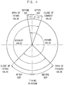
- FIGS. 3 and 4 are graphs chart showing operations of the crankshaft in FIG. 1
- FIG. 5 is a graph showing performances of the engine with respect to overlap angles in FIG. 1
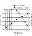
- FIG. 6 is a graph showing performances of the engine with respect to an opening timing of an intake valve in the engine of FIG. 1
- FIG. 7 is a graph showing performances of the engine with respect to a closing timing of an exhaust valve in the engine of FIG. 1
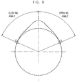
- FIG. 8 is a graph showing a closing angle of an intake cam and an opening angle of an exhaust cam in FIG. 1 .
- an engine may include a cylinder 10, an intake valve 20, a piston 30, an exhaust valve 40 and a crankshaft 50.
- the cylinder 10 may have a cylinder bore 12.
- the intake valve 20 may be configured to introduce an air and a fuel into the cylinder bore 12.
- the piston 30 may be slidably arranged in the cylinder bore 12.
- the exhaust valve 40 may be configured to discharge an exhaust gas generated in the cylinder bore 12.
- the crankshaft 50 may be connected with the piston 30.
- the cylinder 10 may be configured to move the piston 30 using an explosive power generated from the fuel and the air in the cylinder bore 12. Numbers of the cylinder 10 may be determined in accordance with a desired power.
- the cylinder 10 may have heat resistance and corrosion resistance.
- the cylinder 10 may include a special cast iron, an aluminum alloy, etc.
- the cylinder 10 may have an inner surface to which a special treatment may be performed to prevent the cylinder 10 from being worn.
- the intake valve 20 may introduce the air and the fuel into the cylinder bore 12 through an intake port 22 during an intake stroke of the engine.
- the intake valve 20 may be opened and closed by a locker arm 64 arranged over the intake valve 20.
- a valve spring 44 may function as to close the intake valve 20 at an end of the intake stroke and also maintain the closed state of the intake valve 20.
- the piston 30 may be slidably arranged in the cylinder bore 12.
- the piston 30 may be configured to convert the explosive force of the exhaust gas, which may be generated by combusting the fuel, into a linear driving force.
- the piston 30 may be reciprocally moved in the cylinder bore 12 to compress the air and the fuel in the cylinder bore 12.
- the piston 30 may transmit an expansion power generated by combusting the air and the fuel to a connecting rod 34.
- the piston 30 may include piston rings 32 on an outer surface of the piston 30.
- the piston rings 32 may function as to seal between the cylinder 10 and the piston 30 and scrap oils on the inner surface of the cylinder 10.
- the exhaust valve 40 may discharge the exhaust gas generated during an exhaust stroke of the engine.
- the exhaust valve 40 may be opened and closed by the locker arm 64 arranged over the exhaust valve 40.
- the valve spring 44 may function as to close the exhaust valve 40 at an end of the exhaust stroke and also maintain the closed state of the exhaust valve 40.
- the crankshaft 50 may be connected with the piston 30 via the connecting rod 34.
- the crankshaft 50 may convert the linear driving force by the piston 30 into a rotary driving force.
- the crankshaft 50 may include a balance weight 52.
- the linear driving force may be transmitted from the piston 30 to the crankshaft 50 during an explosion stroke of the engine so that the crankshaft 50 may be rotated.
- a force in a direction opposite to a rotation direction of the crankshaft 50 may be applied to the crankshaft 50 during the intake stroke, a compression stroke and the exhaust stroke of the engine.
- the balance weight 52 may generate a rotational inertia to suppress the force applied to the crankshaft 50. That is, the balance weight 52 may suppress imbalance of inertia or a torque generated in the intake stroke, the compression stroke, the explosion stroke and the exhaust stroke.
- the engine may further include a camshaft 60.
- the camshaft 60 may be mechanically connected with the crankshaft 50 to operate the intake valve 20 and the exhaust valve 40.
- the camshaft 60 may be interlocked with the crankshaft 50 by a gear train to receive the rotational driving force from the crankshaft 50.
- the camshaft 60 may include an intake cam 66 and an exhaust cam 68.
- the intake cam 66 may be configured to operate the intake valve 20.
- the exhaust cam 68 may be configured to operate the exhaust valve 40.
- the intake cam 66 and the exhaust cam 68 may make contact with a push rod 62 to move upwardly and downwardly the push rod 62.
- the push rod 62 may be reciprocally moved by the rotation of the camshaft 60.
- the intake cam 66 and the exhaust cam 68 may include noses having a protruded shape to move upwardly and downwardly the push rod 62.
- the linear reciprocal movement of the push rod 62 may rotate the locker arm 64 making contact with the push rod 62.
- the locker arm 64 may be rotated to open or close the intake valve 20 or the exhaust valve 40 connected with the locker arm 64.
- the intake valve 20 and the exhaust valve 40 may be simultaneously opened (overlapped) within a rotation angle of about 3° to about 12° of the crankshaft 50.
- a trapping ratio of the engine with respect to an overlap angle may be as follows.
- the trapping ratio may be a ratio of a mass of the air and the fuel in the cylinder bore 12 with respect to a mass of the air and the fuel introduced through the intake valve 20.
- the trapping ratio may be increased in proportion to a decrease of the overlap angle. That is, because a simultaneous open time of the intake valve 20 and the exhaust valve 40 may be decreased, a slip, which may mean a discharge of the air and the fuel without combustion through the exhaust valve 40.
- a volumetric efficiency of the engine with respect to the overlap angle may be as follows.
- the volumetric efficiency may be a ratio of a mass of an actual air and an actual fuel in the cylinder bore 12 with respect to a mass of an inhalable air and an inhalable fuel into the cylinder bore 12 by one cycle of the engine.
- the volumetric efficiency may be decreased in proportion to a decreased of the overlap angle.
- the decrease of the volumetric efficiency may result in an insufficient inflow of the air and the fuel so that the performance of the engine may be deteriorated.
- a gas inertia effect of the air and the fuel may not be used.
- the intake valve 20 and the exhaust valve 40 may be simultaneously opened within a rotation angle of about 3° to about 6° of the crankshaft 50.
- the intake valve 20 may be opened within a rotation angle of about 1° to about 2° of the crankshaft 50 before the top dead point of the piston 30.
- the exhaust valve 40 may be opened within a rotation angle of about 2° to about 10° of the crankshaft 50 after the top dead point of the piston 30.
- the intake valve 20 may be opened within a rotation angle of about 1° to about 2° of the crankshaft 50.
- the exhaust valve 40 may be opened within a rotation angle of about 2° to about 10° of the crankshaft 50.
- a rotation angle of the camshaft 60 may be controlled in accordance with the rotation angle of the crankshaft 50.
- the intake valve 20 and the exhaust valve 40 may be simultaneously opened within a rotation angle of about 1.5° to about 3° of the camshaft 60.
- a closing angle of the intake cam 66 may be about 65° to about 69°.
- An opening angle of the exhaust cam 68 may be about 73° to about 77°.
- the opening angle of the exhaust cam 68 may be measured from a center point of the nose to an end of a lob in the exhaust cam 68.
- the closing angle of the intake cam 66 may be measured from a center point of the nose to an end of a lob in the intake cam 66.
- a phase difference between the noses of the intake cam 66 and the exhaust cam 68 may be about 107.75° to about 112.25°.
- the phase difference may be determined in accordance with an RPM of the camshaft 60 of two times that of the crankshaft 50.
- a phase difference between the noses of the intake cam 66 and the exhaust cam 68 may be obtained by measuring an angle difference between the noses of the intake cam 66 and the exhaust cam 68.
- the intake cam 66 and the exhaust cam 68 may be provided to the single camshaft 60.
- the intake cam 66 and the exhaust cam 68 may be provided to different camshafts having a substantially same RPM.
- the trapping ratio may be remarkably decreased because the overlap section may be increased.
- the phase difference between the noses of the intake cam 66 and the exhaust cam 68 may be above about 112.25°, the volumetric efficiency may be remarkably decreased because the overlap section may be decreased.
- the engine may include a compressed natural gas (CNG) engine.
- the engine may further include a fuel supply system configured to supply the compressed natural gas to the cylinder 10.
- the fuel supply system may supply a compressed fuel gas having a low temperature in a gas tank to the CNG engine.
- the fuel supply system may include a tank configured to receive a compressed fuel gas, a gas regulator, a heat exchanger and a fuel metering valve.
- the gas regulator, the heat exchanger and the fuel metering valve may be sequentially connected to the tank.
- the engine may include the crankshaft 50 having the overlap angle of about 3° to about 12°.
- the overlap angle may be between about 3° to about 12°, the engine may have a maximum performance.
Landscapes
- Engineering & Computer Science (AREA)
- Chemical & Material Sciences (AREA)
- Mechanical Engineering (AREA)
- General Engineering & Computer Science (AREA)
- Combustion & Propulsion (AREA)
- Chemical Kinetics & Catalysis (AREA)
- General Chemical & Material Sciences (AREA)
- Oil, Petroleum & Natural Gas (AREA)
- Output Control And Ontrol Of Special Type Engine (AREA)
- Valve-Gear Or Valve Arrangements (AREA)
Abstract
Description
- Example embodiments relate to an engine. More particularly, example embodiments relate to a compressed natural gas (CNG) engine.
- Most of engines may have an overlap at which an intake valve and an exhaust valve may be simultaneously opened. Generally, the intake valve may be opened before a top dead point of a piston and closed after a bottom dead point of the piston. The exhaust valve may be opened before the top dead point and closed after the top dead point.
- Particularly, when the intake valve may be so quickly closed, an amount of an intake air may be decreased to reduce a volumetric efficiency. In contrast, the intake valve may be closed lately, a mixture in a cylinder may flow backwardly toward an intake port to reduce the volumetric efficiency. Further, when the exhaust valve may be so quickly closed, an exhaust gas may not be sufficiently exhausted. In contrast, the exhaust valve may be closed late, the exhaust gas may flow backwardly from an exhaust port to the cylinder to reduce the volumetric efficiency. The mixture, which may not be combusted in the cylinder, may be exhausted through the exhaust port into decrease fuel efficiency, thereby causing fail of compliance with emission regulations with respect to a CH4 gas.
- In a compressed natural gas (CNG) engine, a fuel and an air may be mixed from an intake port to form a mixture. The mixture may be introduced into a cylinder. Therefore, a performance of the CNG engine may be dependent upon opening times and closing times of an intake valve and an exhaust valve.
- Example embodiments provide an engine that may be capable of reducing a slip of a CH4 gas and improving a volumetric efficiency.
- According to example embodiments, there may be provided an engine. The engine may include a cylinder, an intake valve, a piston, an exhaust valve and a crankshaft. The cylinder may include a cylinder bore. The intake valve may be configured to introduce a fuel and an air into the cylinder bore. The piston may be slidably arranged in the cylinder bore. The piston may be configured to convert an explosive power of an exhaust gas, which may be generated by combusting the fuel, into a linear driving force. The exhaust valve may be configured to exhaust the exhaust gas from the cylinder bore. The crankshaft may be connected with the piston to convert the linear driving force into a rotary driving force. The intake valve and the exhaust valve may be simultaneously opened within a rotation angle of about 3° to about 12° of the crankshaft.
- In example embodiments, the intake valve and the exhaust valve may be simultaneously opened within a rotation angle of about 3° to about 6° of the crankshaft.
- In example embodiments, the intake valve may be opened within a rotation angle of about 1° to about 2° of the crankshaft before a top dead point of the piston.
- In example embodiments, the exhaust valve may be opened within a rotation angle of about 2° to about 10° of the crankshaft after the top dead point of the piston.
- In example embodiments, a section after the top dead point of the piston in a total section where the intake valve and the exhaust valve may be simultaneously opened may be wider than a section before the top dead point of the piston.
- In example embodiments, the engine may further include a camshaft connected with the crankshaft to operate the intake valve and the exhaust valve.
- In example embodiments, the intake valve and the exhaust valve may be simultaneously opened within a rotation angle of about 1.5° to about 3° of the crankshaft.
- In example embodiments, the engine may include a CNG engine.
- In example embodiments, the engine may further include a fuel supply system configured to supply a compressed natural gas to the cylinder.
- According to example embodiments, there may be provided an engine. The engine may include a cylinder, an intake valve, an exhaust valve, a camshaft, an intake cam and an exhaust cam. The cylinder may include a cylinder bore. The intake valve may be configured to introduce a fuel and an air into the cylinder bore. The exhaust valve may be configured to exhaust an exhaust gas from the cylinder bore. The camshaft may be configured to operate the intake valve and the exhaust valve. The intake cam may be combined with the camshaft to open/close the intake valve. The exhaust cam may be combined with the camshaft to open/close the exhaust valve. A closing angle of the intake cam may be about 65° to about 69°. An opening angle of the exhaust cam may be about 73° to about 77°.
- In example embodiments, the opening angle of the exhaust cam may be measured from a center point of a nose to an end of a lob in the exhaust cam. The closing angle of the intake cam may be measured from a center point of a nose to an end of a lob in the intake cam.
- In example embodiments, a phase difference between the noses in the intake cam and the exhaust cam may be about 107.75° to about 112.25°.
- In example embodiments, the phase difference between the noses in the intake cam and the exhaust cam may be obtained by measuring an angle difference between the noses in the intake cam and the exhaust cam with respect to a rotational direction of the camshaft.
- In example embodiments, the intake cam and the exhaust cam may be provided to the same cam shaft. Alternatively, the intake cam and the exhaust cam may be provided to different camshafts having substantially revolutions per minute (RPM).
- According to example embodiments, an overlap, which may mean the period during the valve timing where bot of the intake and exhaust valves may be opened, may be controlled to maintain a volumetric efficiency of the engine and improve a fuel efficiency of the engine. Further, a slip, which may mean a direct discharge of the non-combusted fuel to an exhaust port, may be reduced by decreasing an overlap angle. Therefore, the engine may satisfy emission regulations with respect to a CH4 gas.
- Example embodiments will be more clearly understood from the following detailed description taken in conjunction with the accompanying drawings.
FIGS. 1 to 8 represent non-limiting, example embodiments as described herein. -
FIG. 1 is a cross-sectional view illustrating an engine in accordance with example embodiments; -
FIG. 2 is a perspective view illustrating a crankshaft inFIG. 1 ; -
FIGS. 3 and4 are graphs chart showing operations of the crankshaft inFIG. 1 ; -
FIG. 5 is a graph showing performances of the engine with respect to overlap angles inFIG. 1 ; -
FIG. 6 is a graph showing performances of the engine with respect to an opening timing of an intake valve in the engine ofFIG. 1 ; -
FIG. 7 is a graph showing performances of the engine with respect to a closing timing of an exhaust valve in the engine ofFIG. 1 ; and -
FIG. 8 is a graph showing a closing angle of an intake cam and an opening angle of an exhaust cam inFIG. 1 . - Various example embodiments will be described more fully hereinafter with reference to the accompanying drawings, in which some example embodiments are shown. The present invention may, however, be embodied in many different forms and should not be construed as limited to the example embodiments set forth herein. Rather, these example embodiments are provided so that this disclosure will be thorough and complete, and will fully convey the scope of the present invention to those skilled in the art. In the drawings, the sizes and relative sizes of layers and regions may be exaggerated for clarity.
- It will be understood that when an element or layer is referred to as being "on," "connected to" or "coupled to" another element or layer, it can be directly on, connected or coupled to the other element or layer or intervening elements or layers may be present. In contrast, when an element is referred to as being "directly on," "directly connected to" or "directly coupled to" another element or layer, there are no intervening elements or layers present. Like numerals refer to like elements throughout. As used herein, the term "and/or" includes any and all combinations of one or more of the associated listed items.
- It will be understood that, although the terms first, second, third etc. may be used herein to describe various elements, components, regions, layers and/or sections, these elements, components, regions, layers and/or sections should not be limited by these terms. These terms are only used to distinguish one element, component, region, layer or section from another region, layer or section. Thus, a first element, component, region, layer or section discussed below could be termed a second element, component, region, layer or section without departing from the teachings of the present invention.
- Spatially relative terms, such as "beneath," "below," "lower," "above," "upper" and the like, may be used herein for ease of description to describe one element or feature's relationship to another element(s) or feature(s) as illustrated in the figures. It will be understood that the spatially relative terms are intended to encompass different orientations of the device in use or operation in addition to the orientation depicted in the figures. For example, if the device in the figures is turned over, elements described as "below" or "beneath" other elements or features would then be oriented "above" the other elements or features. Thus, the exemplary term "below" can encompass both an orientation of above and below. The device may be otherwise oriented (rotated 90 degrees or at other orientations) and the spatially relative descriptors used herein interpreted accordingly.
- The terminology used herein is for the purpose of describing particular example embodiments only and is not intended to be limiting of the present invention. As used herein, the singular forms "a," "an" and "the" are intended to include the plural forms as well, unless the context clearly indicates otherwise. It will be further understood that the terms "comprises" and/or "comprising," when used in this specification, specify the presence of stated features, integers, steps, operations, elements, and/or components, but do not preclude the presence or addition of one or more other features, integers, steps, operations, elements, components, and/or groups thereof.
- Example embodiments are described herein with reference to cross-sectional illustrations that are schematic illustrations of idealized example embodiments (and intermediate structures). As such, variations from the shapes of the illustrations as a result, for example, of manufacturing techniques and/or tolerances, are to be expected. Thus, example embodiments should not be construed as limited to the particular shapes of regions illustrated herein but are to include deviations in shapes that result, for example, from manufacturing. For example, an implanted region illustrated as a rectangle will, typically, have rounded or curved features and/or a gradient of implant concentration at its edges rather than a binary change from implanted to non-implanted region. Likewise, a buried region formed by implantation may result in some implantation in the region between the buried region and the surface through which the implantation takes place. Thus, the regions illustrated in the figures are schematic in nature and their shapes are not intended to illustrate the actual shape of a region of a device and are not intended to limit the scope of the present invention.
- Unless otherwise defined, all terms (including technical and scientific terms) used herein have the same meaning as commonly understood by one of ordinary skill in the art to which this invention belongs. It will be further understood that terms, such as those defined in commonly used dictionaries, should be interpreted as having a meaning that is consistent with their meaning in the context of the relevant art and will not be interpreted in an idealized or overly formal sense unless expressly so defined herein.
- Hereinafter, example embodiments will be explained in detail with reference to the accompanying drawings.
-
FIG. 1 is a cross-sectional view illustrating an engine in accordance with example embodiments,FIG. 2 is a perspective view illustrating a crankshaft inFIG. 1 ,FIGS. 3 and4 are graphs chart showing operations of the crankshaft inFIG. 1 ,FIG. 5 is a graph showing performances of the engine with respect to overlap angles inFIG. 1 ,FIG. 6 is a graph showing performances of the engine with respect to an opening timing of an intake valve in the engine ofFIG. 1 ,FIG. 7 is a graph showing performances of the engine with respect to a closing timing of an exhaust valve in the engine ofFIG. 1 , andFIG. 8 is a graph showing a closing angle of an intake cam and an opening angle of an exhaust cam inFIG. 1 . - Referring to
FIGS. 1 to 8 , an engine may include acylinder 10, anintake valve 20, apiston 30, anexhaust valve 40 and acrankshaft 50. Thecylinder 10 may have acylinder bore 12. Theintake valve 20 may be configured to introduce an air and a fuel into the cylinder bore 12. Thepiston 30 may be slidably arranged in the cylinder bore 12. Theexhaust valve 40 may be configured to discharge an exhaust gas generated in the cylinder bore 12. Thecrankshaft 50 may be connected with thepiston 30. - The
cylinder 10 may be configured to move thepiston 30 using an explosive power generated from the fuel and the air in the cylinder bore 12. Numbers of thecylinder 10 may be determined in accordance with a desired power. Thecylinder 10 may have heat resistance and corrosion resistance. Thus, thecylinder 10 may include a special cast iron, an aluminum alloy, etc. Thecylinder 10 may have an inner surface to which a special treatment may be performed to prevent thecylinder 10 from being worn. - The
intake valve 20 may introduce the air and the fuel into the cylinder bore 12 through anintake port 22 during an intake stroke of the engine. - The
intake valve 20 may be opened and closed by alocker arm 64 arranged over theintake valve 20. Avalve spring 44 may function as to close theintake valve 20 at an end of the intake stroke and also maintain the closed state of theintake valve 20. - The
piston 30 may be slidably arranged in the cylinder bore 12. Thepiston 30 may be configured to convert the explosive force of the exhaust gas, which may be generated by combusting the fuel, into a linear driving force. Thepiston 30 may be reciprocally moved in the cylinder bore 12 to compress the air and the fuel in the cylinder bore 12. Thepiston 30 may transmit an expansion power generated by combusting the air and the fuel to a connectingrod 34. - The
piston 30 may includepiston rings 32 on an outer surface of thepiston 30. The piston rings 32 may function as to seal between thecylinder 10 and thepiston 30 and scrap oils on the inner surface of thecylinder 10. - The
exhaust valve 40 may discharge the exhaust gas generated during an exhaust stroke of the engine. Theexhaust valve 40 may be opened and closed by thelocker arm 64 arranged over theexhaust valve 40. Thevalve spring 44 may function as to close theexhaust valve 40 at an end of the exhaust stroke and also maintain the closed state of theexhaust valve 40. - The
crankshaft 50 may be connected with thepiston 30 via the connectingrod 34. Thecrankshaft 50 may convert the linear driving force by thepiston 30 into a rotary driving force. - The
crankshaft 50 may include abalance weight 52. The linear driving force may be transmitted from thepiston 30 to thecrankshaft 50 during an explosion stroke of the engine so that thecrankshaft 50 may be rotated. A force in a direction opposite to a rotation direction of thecrankshaft 50 may be applied to thecrankshaft 50 during the intake stroke, a compression stroke and the exhaust stroke of the engine. Thebalance weight 52 may generate a rotational inertia to suppress the force applied to thecrankshaft 50. That is, thebalance weight 52 may suppress imbalance of inertia or a torque generated in the intake stroke, the compression stroke, the explosion stroke and the exhaust stroke. - In example embodiments, the engine may further include a
camshaft 60. Thecamshaft 60 may be mechanically connected with thecrankshaft 50 to operate theintake valve 20 and theexhaust valve 40. Thecamshaft 60 may be interlocked with thecrankshaft 50 by a gear train to receive the rotational driving force from thecrankshaft 50. - The
camshaft 60 may include anintake cam 66 and anexhaust cam 68. Theintake cam 66 may be configured to operate theintake valve 20. Theexhaust cam 68 may be configured to operate theexhaust valve 40. Theintake cam 66 and theexhaust cam 68 may make contact with apush rod 62 to move upwardly and downwardly thepush rod 62. Thus, thepush rod 62 may be reciprocally moved by the rotation of thecamshaft 60. Theintake cam 66 and theexhaust cam 68 may include noses having a protruded shape to move upwardly and downwardly thepush rod 62. - The linear reciprocal movement of the
push rod 62 may rotate thelocker arm 64 making contact with thepush rod 62. Thelocker arm 64 may be rotated to open or close theintake valve 20 or theexhaust valve 40 connected with thelocker arm 64. - In example embodiments, the
intake valve 20 and theexhaust valve 40 may be simultaneously opened (overlapped) within a rotation angle of about 3° to about 12° of thecrankshaft 50. - Referring to
FIG. 5 , when the engine may be rotated at a speed of about 1,000 RPM, a trapping ratio of the engine with respect to an overlap angle may be as follows. The trapping ratio may be a ratio of a mass of the air and the fuel in the cylinder bore 12 with respect to a mass of the air and the fuel introduced through theintake valve 20. - The trapping ratio may be increased in proportion to a decrease of the overlap angle. That is, because a simultaneous open time of the
intake valve 20 and theexhaust valve 40 may be decreased, a slip, which may mean a discharge of the air and the fuel without combustion through theexhaust valve 40. - When the engine may be rotated at a speed of about 1,000 RPM, a volumetric efficiency of the engine with respect to the overlap angle may be as follows. The volumetric efficiency may be a ratio of a mass of an actual air and an actual fuel in the cylinder bore 12 with respect to a mass of an inhalable air and an inhalable fuel into the cylinder bore 12 by one cycle of the engine.
- Referring to
FIG. 4 , the volumetric efficiency may be decreased in proportion to a decreased of the overlap angle. The decrease of the volumetric efficiency may result in an insufficient inflow of the air and the fuel so that the performance of the engine may be deteriorated. A gas inertia effect of the air and the fuel may not be used. - In example embodiments, the
intake valve 20 and theexhaust valve 40 may be simultaneously opened within a rotation angle of about 3° to about 6° of thecrankshaft 50. - In example embodiments, the
intake valve 20 may be opened within a rotation angle of about 1° to about 2° of thecrankshaft 50 before the top dead point of thepiston 30. Theexhaust valve 40 may be opened within a rotation angle of about 2° to about 10° of thecrankshaft 50 after the top dead point of thepiston 30. - Referring to
FIG. 6 , when an opening timing of theintake valve 20 may be advanced by about 2° than the top dead point of thepiston 30, the volumetric efficiency may be increased, but the trapping ratio may be remarkably decreased. Further, when an opening timing of theintake valve 20 may be late by about 1° than the top dead point of thepiston 30, the trapping ratio may be slightly increased, but the volumetric efficiency may be remarkably decreased. Thus, theintake valve 20 may be opened within a rotation angle of about 1° to about 2° of thecrankshaft 50. - Referring to
FIG. 7 , when a closing timing of theexhaust valve 40 may be advanced by about 2° than the top dead point of thepiston 30, the volumetric efficiency may be remarkably decreased. Further, when a closing timing of theexhaust valve 40 may be late by about 10° than the top dead point of thepiston 30, the trapping ratio may be remarkably decreased. Thus, theexhaust valve 40 may be opened within a rotation angle of about 2° to about 10° of thecrankshaft 50. - A rotation angle of the
camshaft 60 may be controlled in accordance with the rotation angle of thecrankshaft 50. In example embodiments, theintake valve 20 and theexhaust valve 40 may be simultaneously opened within a rotation angle of about 1.5° to about 3° of thecamshaft 60. - Referring to
FIG. 8 , a closing angle of theintake cam 66 may be about 65° to about 69°. An opening angle of theexhaust cam 68 may be about 73° to about 77°. - The opening angle of the
exhaust cam 68 may be measured from a center point of the nose to an end of a lob in theexhaust cam 68. The closing angle of theintake cam 66 may be measured from a center point of the nose to an end of a lob in theintake cam 66. - A phase difference between the noses of the
intake cam 66 and theexhaust cam 68 may be about 107.75° to about 112.25°. The phase difference may be determined in accordance with an RPM of thecamshaft 60 of two times that of thecrankshaft 50. - A phase difference between the noses of the
intake cam 66 and theexhaust cam 68 may be obtained by measuring an angle difference between the noses of theintake cam 66 and theexhaust cam 68. - In example embodiments, the
intake cam 66 and theexhaust cam 68 may be provided to thesingle camshaft 60. Alternatively, theintake cam 66 and theexhaust cam 68 may be provided to different camshafts having a substantially same RPM. - When the phase difference between the noses of the
intake cam 66 and theexhaust cam 68 may be below about 107.75°, the trapping ratio may be remarkably decreased because the overlap section may be increased. - In contrast, when the phase difference between the noses of the
intake cam 66 and theexhaust cam 68 may be above about 112.25°, the volumetric efficiency may be remarkably decreased because the overlap section may be decreased. - In example embodiments, the engine may include a compressed natural gas (CNG) engine. The engine may further include a fuel supply system configured to supply the compressed natural gas to the
cylinder 10. The fuel supply system may supply a compressed fuel gas having a low temperature in a gas tank to the CNG engine. - In example embodiments, the fuel supply system may include a tank configured to receive a compressed fuel gas, a gas regulator, a heat exchanger and a fuel metering valve. The gas regulator, the heat exchanger and the fuel metering valve may be sequentially connected to the tank.
- In example embodiments, the engine may include the
crankshaft 50 having the overlap angle of about 3° to about 12°. When the overlap angle may be between about 3° to about 12°, the engine may have a maximum performance. - The foregoing is illustrative of example embodiments and is not to be construed as limiting thereof. Although a few example embodiments have been described, those skilled in the art will readily appreciate that many modifications are possible in the example embodiments without materially departing from the novel teachings and advantages of the present invention. Accordingly, all such modifications are intended to be included within the scope of the present invention as defined in the claims. In the claims, means-plus-function clauses are intended to cover the structures described herein as performing the recited function and not only structural equivalents but also equivalent structures. Therefore, it is to be understood that the foregoing is illustrative of various example embodiments and is not to be construed as limited to the specific example embodiments disclosed, and that modifications to the disclosed example embodiments, as well as other example embodiments, are intended to be included within the scope of the appended claims.
Claims (14)
- An engine comprising:a cylinder having a cylinder bore;an intake valve configured to introduce an air and a fuel into the cylinder bore;a piston slidably arranged in the cylinder bore to convert an explosive force, which is generated by combusting the fuel, into a linear driving force;an exhaust valve configured to exhaust an exhaust gas from the cylinder bore; anda crankshaft connected with the piston to convert the linear driving force into a rotational driving force,wherein the intake valve and the exhaust valve are simultaneously opened within a rotation angle of about 3° to about 12° of the crankshaft.
- The engine of claim 1, wherein the intake valve and the exhaust valve are simultaneously opened within the rotation angle of about 3° to about 6° of the crankshaft.
- The engine of claim 1, wherein the intake valve is opened within the rotation angle of about 1° to about 2° of the crankshaft before a top dead point of the piston.
- The engine of claim 1, wherein the exhaust valve is closed within the rotation angle of about 2° to about 10° of the crankshaft after a top dead point of the piston.
- The engine of claim 1, wherein a section after a top dead point of the piston in a total section in which the intake valve and the exhaust valve are simultaneously opened is wider than a section before the top dead point of the piston in the total section in which the intake valve and the exhaust valve are simultaneously opened.
- The engine of claim 1, further comprising a camshaft connected with the crankshaft to operate the intake valve and the exhaust valve.
- The engine of claim 6, wherein the intake valve and the exhaust valve are simultaneously opened within a rotation angle of about 1.5° to about 3°of the camshaft.
- The engine of claim 7, wherein a phase difference between a nose of an intake cam in the intake valve and a nose of an exhaust cam in the exhaust valve is about 107.75° to about 112.25°.
- The engine of claim 1, wherein the engine comprises a compressed natural gas (CNG) engine.
- The engine of claim 9, further comprising a fuel supply system configured to supply the CNG to the cylinder.
- An engine comprising:a cylinder having a cylinder bore;an intake valve configured to introduce an air and a fuel into the cylinder bore;an exhaust valve configured to exhaust an exhaust gas from the cylinder bore;a camshaft configured to operate the intake valve and the exhaust valve;an intake cam combined with the camshaft to open/close the intake valve; andan exhaust cam combined with the camshaft to open/close the exhaust valve,wherein a phase difference between a nose of the intake cam and a nose of the exhaust cam is about 107.75° to about 112.25°.
- The engine of claim 11, wherein the intake valve and the exhaust valve are simultaneously opened within the rotation angle of about 1.5° to about 3° of the camshaft.
- The engine of claim 11, wherein a closing angle of the intake cam is narrower than an opening angle of the exhaust cam.
- The engine of claim 13, wherein the closing angle of the intake cam is about 65° to about 69°, and the opening angle of the exhaust cam is about 73° to about 77°.
Applications Claiming Priority (2)
| Application Number | Priority Date | Filing Date | Title |
|---|---|---|---|
| KR1020140034370A KR20150111047A (en) | 2014-03-25 | 2014-03-25 | Engine |
| PCT/KR2015/002938 WO2015147554A1 (en) | 2014-03-25 | 2015-03-25 | Engine |
Publications (3)
| Publication Number | Publication Date |
|---|---|
| EP3124772A1 true EP3124772A1 (en) | 2017-02-01 |
| EP3124772A4 EP3124772A4 (en) | 2017-08-09 |
| EP3124772B1 EP3124772B1 (en) | 2021-05-12 |
Family
ID=54195983
Family Applications (1)
| Application Number | Title | Priority Date | Filing Date |
|---|---|---|---|
| EP15768428.3A Active EP3124772B1 (en) | 2014-03-25 | 2015-03-25 | Engine |
Country Status (5)
| Country | Link |
|---|---|
| US (1) | US10107209B2 (en) |
| EP (1) | EP3124772B1 (en) |
| KR (2) | KR20150111047A (en) |
| CN (1) | CN106103945A (en) |
| WO (1) | WO2015147554A1 (en) |
Families Citing this family (1)
| Publication number | Priority date | Publication date | Assignee | Title |
|---|---|---|---|---|
| SE541503C2 (en) * | 2016-06-07 | 2019-10-22 | Scania Cv Ab | Four Stroke Internal Combustion Engine and thereto-related Method |
Family Cites Families (30)
| Publication number | Priority date | Publication date | Assignee | Title |
|---|---|---|---|---|
| US4703734A (en) * | 1985-03-06 | 1987-11-03 | Nissan Motor Co., Ltd. | Multi-valve internal combustion engine |
| DE4232044C2 (en) * | 1991-09-26 | 1998-01-29 | Mazda Motor | Internal combustion engine with spark ignition |
| US5161497A (en) * | 1992-03-11 | 1992-11-10 | Ford Motor Company | Variable valve timing operated engine |
| US6125801A (en) * | 1997-11-25 | 2000-10-03 | Mendler; Edward Charles | Lean-burn variable compression ratio engine |
| JP3700409B2 (en) * | 1998-09-04 | 2005-09-28 | トヨタ自動車株式会社 | 3D cam valve lifter and variable valve operating device |
| US6761147B2 (en) * | 2000-10-18 | 2004-07-13 | Denso Corporation | Control apparatus and method for internal combustion engine |
| JP3625456B2 (en) * | 2002-07-16 | 2005-03-02 | 三菱電機株式会社 | Valve timing control device for internal combustion engine |
| US6810844B2 (en) * | 2002-12-10 | 2004-11-02 | Delphi Technologies, Inc. | Method for 3-step variable valve actuation |
| JP2004278313A (en) * | 2003-03-12 | 2004-10-07 | Honda Motor Co Ltd | Engine valve drive |
| JP4357284B2 (en) * | 2003-05-15 | 2009-11-04 | トヨタ自動車株式会社 | Control device for internal combustion engine |
| US7707992B2 (en) * | 2003-10-31 | 2010-05-04 | Woodward Governor Company | Method and apparatus for controlling exhaust gas recirculation and start of combustion in reciprocating compression ignition engines with an ignition system with ionization measurement |
| JP4278151B2 (en) * | 2004-01-20 | 2009-06-10 | 本田技研工業株式会社 | Control method for internal combustion engine |
| JP4306586B2 (en) * | 2004-10-26 | 2009-08-05 | トヨタ自動車株式会社 | Valve characteristic control device for internal combustion engine |
| JP4475221B2 (en) | 2005-03-11 | 2010-06-09 | トヨタ自動車株式会社 | engine |
| JP4429204B2 (en) * | 2005-05-12 | 2010-03-10 | 富士通テン株式会社 | Variable valve controller |
| DK1739296T3 (en) * | 2005-06-30 | 2013-06-03 | Waertsilae Nsd Schweiz Ag | Method for optimizing an operating parameter in a piston combustion engine and piston combustion engine |
| US7178493B2 (en) * | 2005-07-08 | 2007-02-20 | Gm Global Technology Operations, Inc. | Method and system to avoid piston-valve collision |
| JP2007023814A (en) * | 2005-07-13 | 2007-02-01 | Toyota Motor Corp | Variable valve operating device for internal combustion engine |
| JP4127704B2 (en) * | 2005-09-07 | 2008-07-30 | 三菱電機株式会社 | Internal combustion engine control device |
| US7325521B1 (en) * | 2006-08-02 | 2008-02-05 | Ford Global Technologies, Llc | System and method for improved cam retard |
| DE102007028513A1 (en) | 2007-06-21 | 2008-12-24 | Robert Bosch Gmbh | Internal combustion engine and method for operating an internal combustion engine |
| JP4743287B2 (en) * | 2009-02-04 | 2011-08-10 | トヨタ自動車株式会社 | Control device for variable valve gear |
| JP2010255475A (en) * | 2009-04-22 | 2010-11-11 | Yamaha Motor Co Ltd | Spark ignition internal combustion engine |
| JP5168233B2 (en) | 2009-05-28 | 2013-03-21 | 日産自動車株式会社 | Engine fuel injection control device |
| JP5535695B2 (en) * | 2010-03-08 | 2014-07-02 | 忠孝 山手 | engine |
| US8347857B2 (en) | 2010-06-24 | 2013-01-08 | GM Global Technology Operations LLC | Method and device for improving charged engines |
| DE102010033005A1 (en) * | 2010-07-31 | 2012-02-02 | Daimler Ag | Internal combustion engine and associated operating method |
| DE102010045710A1 (en) * | 2010-09-16 | 2012-03-22 | Volkswagen Ag | Method for operating an internal combustion engine with variable valve drive |
| US9133795B2 (en) * | 2012-01-06 | 2015-09-15 | Woodward, Inc. | Engine using split flow exhaust system and methods |
| JP6015490B2 (en) * | 2013-02-26 | 2016-10-26 | マツダ株式会社 | Engine valve gear |
-
2014
- 2014-03-25 KR KR1020140034370A patent/KR20150111047A/en active Pending
-
2015
- 2015-03-25 US US15/128,013 patent/US10107209B2/en active Active
- 2015-03-25 KR KR1020167024849A patent/KR101858467B1/en active Active
- 2015-03-25 EP EP15768428.3A patent/EP3124772B1/en active Active
- 2015-03-25 CN CN201580015916.7A patent/CN106103945A/en active Pending
- 2015-03-25 WO PCT/KR2015/002938 patent/WO2015147554A1/en not_active Ceased
Also Published As
| Publication number | Publication date |
|---|---|
| US10107209B2 (en) | 2018-10-23 |
| EP3124772A4 (en) | 2017-08-09 |
| WO2015147554A1 (en) | 2015-10-01 |
| KR20160119214A (en) | 2016-10-12 |
| EP3124772B1 (en) | 2021-05-12 |
| KR20150111047A (en) | 2015-10-05 |
| US20170096948A1 (en) | 2017-04-06 |
| KR101858467B1 (en) | 2018-05-16 |
| CN106103945A (en) | 2016-11-09 |
Similar Documents
| Publication | Publication Date | Title |
|---|---|---|
| CN105637186B (en) | Divide the spool shuttle bridging valve in cycle engine | |
| US8695544B2 (en) | High expansion ratio internal combustion engine | |
| JP6742793B2 (en) | Internal combustion engine | |
| WO2012048301A4 (en) | Variable compression ratio systems for opposed-piston and other internal combustion engines, and related methods of manufacture and use | |
| JP2013053610A (en) | Variable valve device | |
| CA2899875A1 (en) | Control system of a gaseous fueled engine with a cam phaser for improving the engine start | |
| EP2785996B1 (en) | Crossover valve in double piston cycle engine | |
| US20130087117A1 (en) | Head assembly and valve-less internal combustion engine | |
| CN106246343A (en) | The double expansion internal combustion engine of single shaft | |
| US10107209B2 (en) | Engine | |
| RU2623334C2 (en) | Method of heat cycle formation and device for its implementation | |
| RU2529982C2 (en) | Engine valve drive | |
| US20150101553A1 (en) | Engine having continuous variable timing device | |
| CN107110032A (en) | Diesel engine and method for operating a diesel engine | |
| US11808231B2 (en) | Negative pressure operating method | |
| US20130213341A1 (en) | Engine having piston with l-shaped timing ring | |
| JP2014234707A (en) | Internal combustion engine | |
| WO2012035285A1 (en) | Six stroke 'blackburn cycle' engine | |
| US8720391B2 (en) | Pre-combustion cycle pressurisation system | |
| US9404428B1 (en) | Variable-expansion-ratio engine | |
| US11988160B2 (en) | Valve control apparatus for engine | |
| Dragunov | Improvement of reciprocating internal combustion engines on the basis of new designs timing mechanisms | |
| US10253680B2 (en) | Internal combustion engine having fuel/air induction system | |
| GB2503745A (en) | Hybrid-valve four stroke engine | |
| JP2012241704A (en) | Four-cycle reciprocating engine |
Legal Events
| Date | Code | Title | Description |
|---|---|---|---|
| STAA | Information on the status of an ep patent application or granted ep patent |
Free format text: STATUS: THE INTERNATIONAL PUBLICATION HAS BEEN MADE |
|
| PUAI | Public reference made under article 153(3) epc to a published international application that has entered the european phase |
Free format text: ORIGINAL CODE: 0009012 |
|
| STAA | Information on the status of an ep patent application or granted ep patent |
Free format text: STATUS: REQUEST FOR EXAMINATION WAS MADE |
|
| 17P | Request for examination filed |
Effective date: 20160927 |
|
| AK | Designated contracting states |
Kind code of ref document: A1 Designated state(s): AL AT BE BG CH CY CZ DE DK EE ES FI FR GB GR HR HU IE IS IT LI LT LU LV MC MK MT NL NO PL PT RO RS SE SI SK SM TR |
|
| AX | Request for extension of the european patent |
Extension state: BA ME |
|
| DAV | Request for validation of the european patent (deleted) | ||
| DAX | Request for extension of the european patent (deleted) | ||
| A4 | Supplementary search report drawn up and despatched |
Effective date: 20170711 |
|
| RIC1 | Information provided on ipc code assigned before grant |
Ipc: F02M 21/02 20060101ALI20170706BHEP Ipc: F02D 13/02 20060101AFI20170706BHEP Ipc: F01L 1/40 20060101ALI20170706BHEP Ipc: F02B 43/02 20060101ALI20170706BHEP Ipc: F02D 19/02 20060101ALI20170706BHEP |
|
| STAA | Information on the status of an ep patent application or granted ep patent |
Free format text: STATUS: EXAMINATION IS IN PROGRESS |
|
| 17Q | First examination report despatched |
Effective date: 20190520 |
|
| GRAP | Despatch of communication of intention to grant a patent |
Free format text: ORIGINAL CODE: EPIDOSNIGR1 |
|
| STAA | Information on the status of an ep patent application or granted ep patent |
Free format text: STATUS: GRANT OF PATENT IS INTENDED |
|
| INTG | Intention to grant announced |
Effective date: 20201120 |
|
| RIN1 | Information on inventor provided before grant (corrected) |
Inventor name: KIM, KWANG-SOO Inventor name: CHO, JA-YUN |
|
| GRAS | Grant fee paid |
Free format text: ORIGINAL CODE: EPIDOSNIGR3 |
|
| GRAA | (expected) grant |
Free format text: ORIGINAL CODE: 0009210 |
|
| STAA | Information on the status of an ep patent application or granted ep patent |
Free format text: STATUS: THE PATENT HAS BEEN GRANTED |
|
| AK | Designated contracting states |
Kind code of ref document: B1 Designated state(s): AL AT BE BG CH CY CZ DE DK EE ES FI FR GB GR HR HU IE IS IT LI LT LU LV MC MK MT NL NO PL PT RO RS SE SI SK SM TR |
|
| REG | Reference to a national code |
Ref country code: GB Ref legal event code: FG4D |
|
| REG | Reference to a national code |
Ref country code: CH Ref legal event code: EP |
|
| REG | Reference to a national code |
Ref country code: DE Ref legal event code: R096 Ref document number: 602015069257 Country of ref document: DE |
|
| REG | Reference to a national code |
Ref country code: IE Ref legal event code: FG4D |
|
| REG | Reference to a national code |
Ref country code: AT Ref legal event code: REF Ref document number: 1392317 Country of ref document: AT Kind code of ref document: T Effective date: 20210615 |
|
| REG | Reference to a national code |
Ref country code: LT Ref legal event code: MG9D |
|
| REG | Reference to a national code |
Ref country code: AT Ref legal event code: MK05 Ref document number: 1392317 Country of ref document: AT Kind code of ref document: T Effective date: 20210512 |
|
| REG | Reference to a national code |
Ref country code: NL Ref legal event code: MP Effective date: 20210512 |
|
| PG25 | Lapsed in a contracting state [announced via postgrant information from national office to epo] |
Ref country code: LT Free format text: LAPSE BECAUSE OF FAILURE TO SUBMIT A TRANSLATION OF THE DESCRIPTION OR TO PAY THE FEE WITHIN THE PRESCRIBED TIME-LIMIT Effective date: 20210512 Ref country code: FI Free format text: LAPSE BECAUSE OF FAILURE TO SUBMIT A TRANSLATION OF THE DESCRIPTION OR TO PAY THE FEE WITHIN THE PRESCRIBED TIME-LIMIT Effective date: 20210512 Ref country code: BG Free format text: LAPSE BECAUSE OF FAILURE TO SUBMIT A TRANSLATION OF THE DESCRIPTION OR TO PAY THE FEE WITHIN THE PRESCRIBED TIME-LIMIT Effective date: 20210812 Ref country code: AT Free format text: LAPSE BECAUSE OF FAILURE TO SUBMIT A TRANSLATION OF THE DESCRIPTION OR TO PAY THE FEE WITHIN THE PRESCRIBED TIME-LIMIT Effective date: 20210512 Ref country code: HR Free format text: LAPSE BECAUSE OF FAILURE TO SUBMIT A TRANSLATION OF THE DESCRIPTION OR TO PAY THE FEE WITHIN THE PRESCRIBED TIME-LIMIT Effective date: 20210512 |
|
| REG | Reference to a national code |
Ref country code: DE Ref legal event code: R081 Ref document number: 602015069257 Country of ref document: DE Owner name: HYUNDAI DOOSAN INFRACORE CO., LTD., KR Free format text: FORMER OWNER: DOOSAN INFRACORE CO., LTD., INCHEON, KR Ref country code: DE Ref legal event code: R081 Ref document number: 602015069257 Country of ref document: DE Owner name: HD HYUNDAI INFRACORE CO., LTD., KR Free format text: FORMER OWNER: DOOSAN INFRACORE CO., LTD., INCHEON, KR |
|
| PG25 | Lapsed in a contracting state [announced via postgrant information from national office to epo] |
Ref country code: RS Free format text: LAPSE BECAUSE OF FAILURE TO SUBMIT A TRANSLATION OF THE DESCRIPTION OR TO PAY THE FEE WITHIN THE PRESCRIBED TIME-LIMIT Effective date: 20210512 Ref country code: SE Free format text: LAPSE BECAUSE OF FAILURE TO SUBMIT A TRANSLATION OF THE DESCRIPTION OR TO PAY THE FEE WITHIN THE PRESCRIBED TIME-LIMIT Effective date: 20210512 Ref country code: ES Free format text: LAPSE BECAUSE OF FAILURE TO SUBMIT A TRANSLATION OF THE DESCRIPTION OR TO PAY THE FEE WITHIN THE PRESCRIBED TIME-LIMIT Effective date: 20210512 Ref country code: NO Free format text: LAPSE BECAUSE OF FAILURE TO SUBMIT A TRANSLATION OF THE DESCRIPTION OR TO PAY THE FEE WITHIN THE PRESCRIBED TIME-LIMIT Effective date: 20210812 Ref country code: PL Free format text: LAPSE BECAUSE OF FAILURE TO SUBMIT A TRANSLATION OF THE DESCRIPTION OR TO PAY THE FEE WITHIN THE PRESCRIBED TIME-LIMIT Effective date: 20210512 Ref country code: PT Free format text: LAPSE BECAUSE OF FAILURE TO SUBMIT A TRANSLATION OF THE DESCRIPTION OR TO PAY THE FEE WITHIN THE PRESCRIBED TIME-LIMIT Effective date: 20210913 Ref country code: GR Free format text: LAPSE BECAUSE OF FAILURE TO SUBMIT A TRANSLATION OF THE DESCRIPTION OR TO PAY THE FEE WITHIN THE PRESCRIBED TIME-LIMIT Effective date: 20210813 Ref country code: IS Free format text: LAPSE BECAUSE OF FAILURE TO SUBMIT A TRANSLATION OF THE DESCRIPTION OR TO PAY THE FEE WITHIN THE PRESCRIBED TIME-LIMIT Effective date: 20210912 Ref country code: LV Free format text: LAPSE BECAUSE OF FAILURE TO SUBMIT A TRANSLATION OF THE DESCRIPTION OR TO PAY THE FEE WITHIN THE PRESCRIBED TIME-LIMIT Effective date: 20210512 |
|
| RAP4 | Party data changed (patent owner data changed or rights of a patent transferred) |
Owner name: HYUNDAI DOOSAN INFRACORE CO., LTD. |
|
| PG25 | Lapsed in a contracting state [announced via postgrant information from national office to epo] |
Ref country code: NL Free format text: LAPSE BECAUSE OF FAILURE TO SUBMIT A TRANSLATION OF THE DESCRIPTION OR TO PAY THE FEE WITHIN THE PRESCRIBED TIME-LIMIT Effective date: 20210512 |
|
| PG25 | Lapsed in a contracting state [announced via postgrant information from national office to epo] |
Ref country code: SM Free format text: LAPSE BECAUSE OF FAILURE TO SUBMIT A TRANSLATION OF THE DESCRIPTION OR TO PAY THE FEE WITHIN THE PRESCRIBED TIME-LIMIT Effective date: 20210512 Ref country code: SK Free format text: LAPSE BECAUSE OF FAILURE TO SUBMIT A TRANSLATION OF THE DESCRIPTION OR TO PAY THE FEE WITHIN THE PRESCRIBED TIME-LIMIT Effective date: 20210512 Ref country code: DK Free format text: LAPSE BECAUSE OF FAILURE TO SUBMIT A TRANSLATION OF THE DESCRIPTION OR TO PAY THE FEE WITHIN THE PRESCRIBED TIME-LIMIT Effective date: 20210512 Ref country code: EE Free format text: LAPSE BECAUSE OF FAILURE TO SUBMIT A TRANSLATION OF THE DESCRIPTION OR TO PAY THE FEE WITHIN THE PRESCRIBED TIME-LIMIT Effective date: 20210512 Ref country code: CZ Free format text: LAPSE BECAUSE OF FAILURE TO SUBMIT A TRANSLATION OF THE DESCRIPTION OR TO PAY THE FEE WITHIN THE PRESCRIBED TIME-LIMIT Effective date: 20210512 Ref country code: RO Free format text: LAPSE BECAUSE OF FAILURE TO SUBMIT A TRANSLATION OF THE DESCRIPTION OR TO PAY THE FEE WITHIN THE PRESCRIBED TIME-LIMIT Effective date: 20210512 |
|
| REG | Reference to a national code |
Ref country code: DE Ref legal event code: R097 Ref document number: 602015069257 Country of ref document: DE |
|
| PLBE | No opposition filed within time limit |
Free format text: ORIGINAL CODE: 0009261 |
|
| STAA | Information on the status of an ep patent application or granted ep patent |
Free format text: STATUS: NO OPPOSITION FILED WITHIN TIME LIMIT |
|
| 26N | No opposition filed |
Effective date: 20220215 |
|
| PG25 | Lapsed in a contracting state [announced via postgrant information from national office to epo] |
Ref country code: IS Free format text: LAPSE BECAUSE OF FAILURE TO SUBMIT A TRANSLATION OF THE DESCRIPTION OR TO PAY THE FEE WITHIN THE PRESCRIBED TIME-LIMIT Effective date: 20210912 Ref country code: AL Free format text: LAPSE BECAUSE OF FAILURE TO SUBMIT A TRANSLATION OF THE DESCRIPTION OR TO PAY THE FEE WITHIN THE PRESCRIBED TIME-LIMIT Effective date: 20210512 |
|
| PG25 | Lapsed in a contracting state [announced via postgrant information from national office to epo] |
Ref country code: IT Free format text: LAPSE BECAUSE OF FAILURE TO SUBMIT A TRANSLATION OF THE DESCRIPTION OR TO PAY THE FEE WITHIN THE PRESCRIBED TIME-LIMIT Effective date: 20210512 |
|
| PG25 | Lapsed in a contracting state [announced via postgrant information from national office to epo] |
Ref country code: MC Free format text: LAPSE BECAUSE OF FAILURE TO SUBMIT A TRANSLATION OF THE DESCRIPTION OR TO PAY THE FEE WITHIN THE PRESCRIBED TIME-LIMIT Effective date: 20210512 |
|
| REG | Reference to a national code |
Ref country code: CH Ref legal event code: PL |
|
| GBPC | Gb: european patent ceased through non-payment of renewal fee |
Effective date: 20220325 |
|
| REG | Reference to a national code |
Ref country code: BE Ref legal event code: MM Effective date: 20220331 |
|
| PG25 | Lapsed in a contracting state [announced via postgrant information from national office to epo] |
Ref country code: LU Free format text: LAPSE BECAUSE OF NON-PAYMENT OF DUE FEES Effective date: 20220325 Ref country code: LI Free format text: LAPSE BECAUSE OF NON-PAYMENT OF DUE FEES Effective date: 20220331 Ref country code: IE Free format text: LAPSE BECAUSE OF NON-PAYMENT OF DUE FEES Effective date: 20220325 Ref country code: GB Free format text: LAPSE BECAUSE OF NON-PAYMENT OF DUE FEES Effective date: 20220325 Ref country code: FR Free format text: LAPSE BECAUSE OF NON-PAYMENT OF DUE FEES Effective date: 20220331 Ref country code: CH Free format text: LAPSE BECAUSE OF NON-PAYMENT OF DUE FEES Effective date: 20220331 |
|
| PG25 | Lapsed in a contracting state [announced via postgrant information from national office to epo] |
Ref country code: BE Free format text: LAPSE BECAUSE OF NON-PAYMENT OF DUE FEES Effective date: 20220331 |
|
| REG | Reference to a national code |
Ref country code: DE Ref legal event code: R081 Ref document number: 602015069257 Country of ref document: DE Owner name: HD HYUNDAI INFRACORE CO., LTD., KR Free format text: FORMER OWNER: HYUNDAI DOOSAN INFRACORE CO., LTD., INCHEON, KR |
|
| PG25 | Lapsed in a contracting state [announced via postgrant information from national office to epo] |
Ref country code: HU Free format text: LAPSE BECAUSE OF FAILURE TO SUBMIT A TRANSLATION OF THE DESCRIPTION OR TO PAY THE FEE WITHIN THE PRESCRIBED TIME-LIMIT; INVALID AB INITIO Effective date: 20150325 |
|
| PG25 | Lapsed in a contracting state [announced via postgrant information from national office to epo] |
Ref country code: MK Free format text: LAPSE BECAUSE OF FAILURE TO SUBMIT A TRANSLATION OF THE DESCRIPTION OR TO PAY THE FEE WITHIN THE PRESCRIBED TIME-LIMIT Effective date: 20210512 Ref country code: CY Free format text: LAPSE BECAUSE OF FAILURE TO SUBMIT A TRANSLATION OF THE DESCRIPTION OR TO PAY THE FEE WITHIN THE PRESCRIBED TIME-LIMIT Effective date: 20210512 |
|
| PG25 | Lapsed in a contracting state [announced via postgrant information from national office to epo] |
Ref country code: TR Free format text: LAPSE BECAUSE OF FAILURE TO SUBMIT A TRANSLATION OF THE DESCRIPTION OR TO PAY THE FEE WITHIN THE PRESCRIBED TIME-LIMIT Effective date: 20210512 |
|
| PG25 | Lapsed in a contracting state [announced via postgrant information from national office to epo] |
Ref country code: MT Free format text: LAPSE BECAUSE OF FAILURE TO SUBMIT A TRANSLATION OF THE DESCRIPTION OR TO PAY THE FEE WITHIN THE PRESCRIBED TIME-LIMIT Effective date: 20210512 |
|
| PGFP | Annual fee paid to national office [announced via postgrant information from national office to epo] |
Ref country code: DE Payment date: 20260204 Year of fee payment: 12 |